


Languages
Pages
Legal

Sand Cast Pressure Foot – User Guide
Page | 1
TABLE OF CONTENTS
I. Before You Start ............................................................ 2
II. Safety Information ................................................................ 3 1. Risks Specific to Maintenance ........................................... 3
2. Risks Associated with Improper Use and Handling ............ 4
III. Overview .................................................................................. 5
IV. Locations ................................................................................ 5
V. Optional (À La Carte) Components ................................. 7
VI. Checking the Status ............................................................. 9
VII. Installation ............................................................................ 12 1. Mounting Cast Pressure Foot Assembly ............................ 4
2. Preparing Extraction Brackets ............................................ 4
3. Installing Extraction Brackets ............................................. 4
VIII. Installation: Options .......................................................... 13
IX. Testing and Troubleshooting .......................................... 13
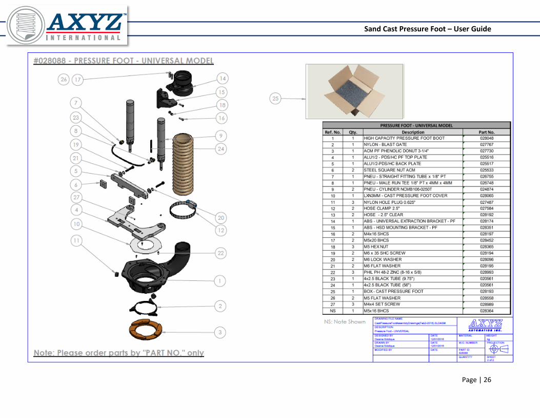
X. Exploded Views ................................................................... 13
1. Universal Model ................................................................. 4
2. ACM Model ........................................................................ 4
XI. Purchase Inquiry and Customer Service ..................... 28

Sand Cast Pressure Foot – User Guide
BEFORE YOU START
This manual covers the application, installation, and maintenance of the new casted
pressure foot, supplied by AXYZ Automation.
In order to obtain a safe, dependable, efficient operation and long life of the cast
pressure foot, the instructions located in this manual must be read, understood, and
followed thoroughly.
The owner is advised to maintain a record of all service work performed with the date
and description of the type of work performed on the unit for future reference.
DISCLAIMER
This document is based on information available during the time of its publication.
Efforts have been put into this manual to provide accurate information. This manual is
NOT intended to cover all details or variations of the product nor is it to provide for every
possible event relating to handling, installation, operation, and/or maintenance.
AXYZ International will not accept any responsibility or liability, in negligence or
otherwise, for any loss or damage which may occur with the use of our products and/or
information.
Information provided in this manual is to serve as an overview guide. Some features
may be mentioned which are not present on all AXYZ International products.
WARNING
Failure to comply with safety standards and/or manual procedures can result in
personal injury, damage to shop personnel, the product and/or the equipment.
Sand Cast Pressure Foot – User Guide
SAFETY INFORMATION
Risks Specific to Maintenance
Maintenance should only be performed under maximum safety conditions.
Ensure all fasteners are properly tightened or installed after removal.
Warning: Never:
NEVER Start any maintenance before making absolutely sure that the tool in the
spindle is completely stationary.
NEVER Start any maintenance on the spindle before disconnecting it from the
main power supply.
NEVER Attempt to clean the spindle or any attachments while it is operating.
Risks Associated with Improper Use and Handling
Avoid physical contact with any moving machinery.
Take precautions to prevent accidental contact: avoid wearing loose or hanging clothing, tie
back long hair, remove jewelry that could get caught in moving parts or cause electric shock.
Wear protective gear such as safety glasses, hearing protection, etc. when in the vicinity of
the operating spindle.
Do not remove, modify or override safety devices or parts on the spindle.
If safety guards or devices must be removed for any reason, ensure that they are properly
installed and functioning before operation.
Before starting the spindle ensure all safety devices are in proper working order.
Loose fasteners can cause serious accidents. Ensure all fasteners are tightened and
installed correctly.
Do not attempt to repair or modify the spindle unless authorized to do so.
Do not use the spindle to cut materials it is not specified for.

Sand Cast Pressure Foot – User Guide
Do not attempt to operate the spindle in an environment where there is risk of explosion.
Use caution when handling tools. Some tools can be extremely sharp and should be
removed prior to servicing the spindle.
Beware of rotating parts even after the spindle is powered down.
Perform all scheduled maintenance on the spindle. Failing to do so can lead to improper
operation and increased wear.
Do not remove warning labels or safety devices from the spindle and all other attachments.
Ensure that all safety labels are legible and not obstructed from view
Sand Cast Pressure Foot – User Guide
OVERVIEW The cast pressure foot is a retrofittable option for the 3HP ELTE, 5HP ELTE, 10HP
ELTE and HSD spindles. The new pressure foot design allows users to keep the
functionality of the HC pressure foot, while eliminating issues related to the dust
collection system. In addition, the new cast pressure foot provides customers with a
more uniform and sleek looking design which is able to accommodate all optional
attachments.
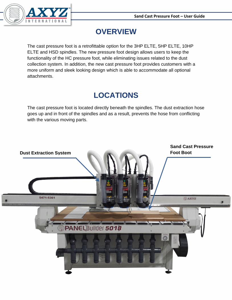
LOCATIONS
The cast pressure foot is located directly beneath the spindles. The dust extraction hose
goes up and in front of the spindles and as a result, prevents the hose from conflicting
with the various moving parts.
Sand Cast Pressure
Foot Boot Dust Extraction System
Sand Cast Pressure Foot – User Guide
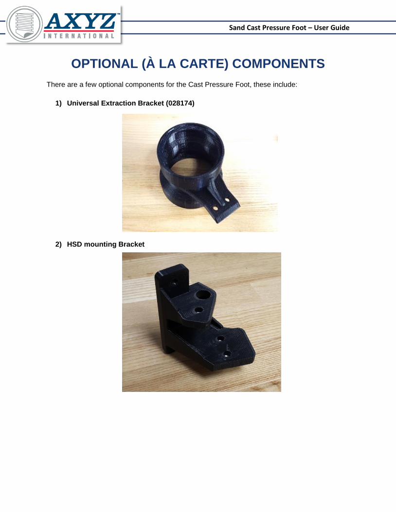
OPTIONAL (À LA CARTE) COMPONENTS
There are a few optional components for the Cast Pressure Foot, these include:
1) Universal Extraction Bracket (028174)
2) HSD mounting Bracket
Sand Cast Pressure Foot – User Guide
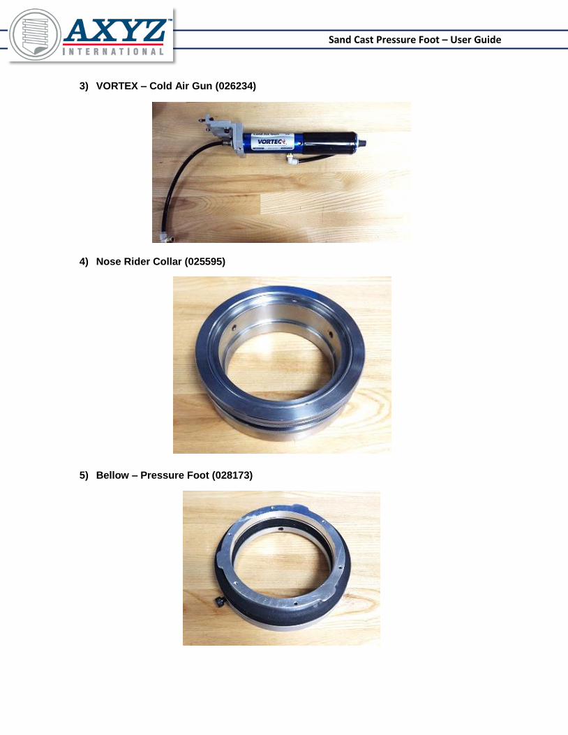
3) VORTEX – Cold Air Gun (026234)
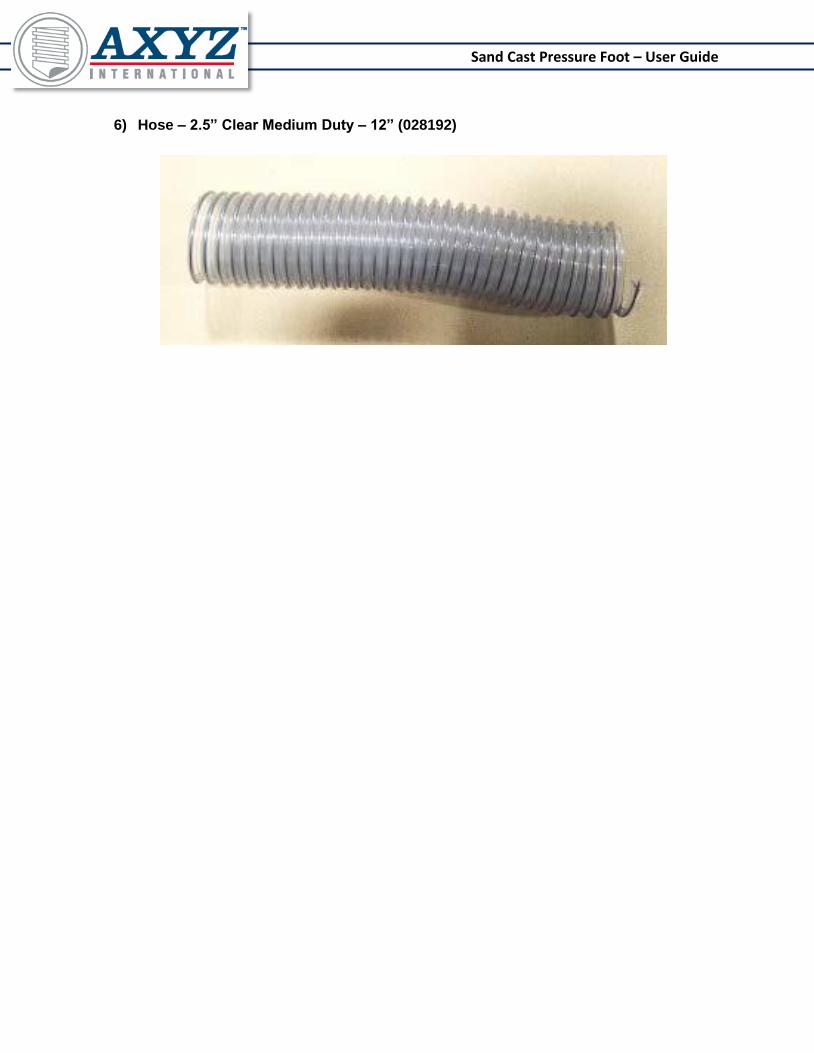
4) Nose Rider Collar (025595)
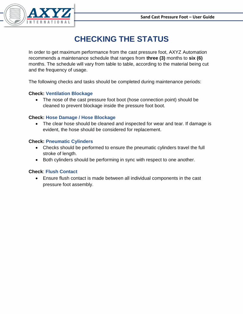
5) Bellow – Pressure Foot (028173)
Sand Cast Pressure Foot – User Guide
6) Hose – 2.5” Clear Medium Duty – 12” (028192)
Sand Cast Pressure Foot – User Guide
CHECKING THE STATUS
In order to get maximum performance from the cast pressure foot, AXYZ Automation
recommends a maintenance schedule that ranges from three (3) months to six (6)
months. The schedule will vary from table to table, according to the material being cut
and the frequency of usage.
The following checks and tasks should be completed during maintenance periods:
Check: Ventilation Blockage
The nose of the cast pressure foot boot (hose connection point) should be
cleaned to prevent blockage inside the pressure foot boot.
Check: Hose Damage / Hose Blockage
The clear hose should be cleaned and inspected for wear and tear. If damage is
evident, the hose should be considered for replacement.
Check: Pneumatic Cylinders
Checks should be performed to ensure the pneumatic cylinders travel the full
stroke of length.
Both cylinders should be performing in sync with respect to one another.
Check: Flush Contact
Ensure flush contact is made between all individual components in the cast
pressure foot assembly.

Sand Cast Pressure Foot – User Guide
INSTALLATION
1. Mounting Cast Pressure Foot Assembly
1) Begin by ensuring that the space between the two square blocks and the back plate of
the mounting assembly is larger than 0.5” (thickness of the Z-plate).
2) Press the head of the screw towards the back plate of the mounting assembly. This is to
keep the distance set in the previous step constant, allowing for easier installation.
3) Locate the two small slots on the bottom of the Z-plate. This is where the threaded portion
of the screw is going to be located.
Notice
Please ensure all required optional components are installed prior
to mounting the Cast Pressure Foot assembly on the carriage.
WARNING
Under NO circumstances should the following procedures be performed while the machine is being
operated. Doing so could result in serious injury and/or damage. In addition, it is strongly advised that all
procedures which require tightening or loosening of bolts be performed manually using the appropriate tools.

Sand Cast Pressure Foot – User Guide
4) Carefully place the assembly under the Z-plate and align the screws with the U-slot.
Gently push upward until flush contact is made between the bottom of the Z-plate and the
mounting hub.
5) Continue using one hand to apply upward pressure on the assembly to ensure flush
contact with the Z-plate. Use an Allen key of the appropriate size to thoroughly tighten the
two screws.
Sand Cast Pressure Foot – User Guide
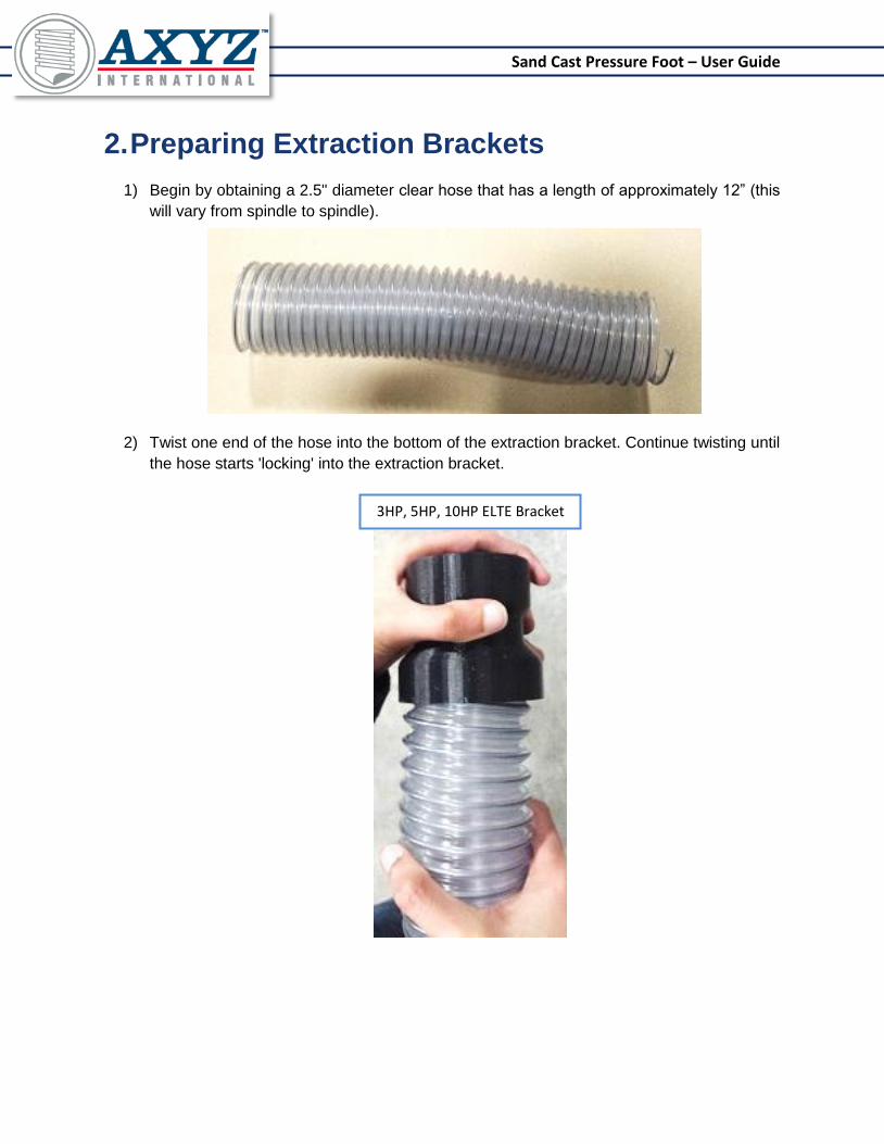
2. Preparing Extraction Brackets
1) Begin by obtaining a 2.5" diameter clear hose that has a length of approximately 12” (this
will vary from spindle to spindle).
2) Twist one end of the hose into the bottom of the extraction bracket. Continue twisting until
the hose starts 'locking' into the extraction bracket.
3HP, 5HP, 10HP ELTE Bracket

Sand Cast Pressure Foot – User Guide
3. Installing Extraction Brackets
i. 3HP, 5HP and 10HP ELTE Spindle
The design of the extraction bracket is universal, as a result, the same extraction bracket can
be used for the 3HP, 5HP, 10HP and HSD spindle.
1) Place the extraction bracket on the mister bracket such that the chamfer is located on the
top face, as shown in the image below.
2) Screw the extraction bracket to the mister bracket using two M5x16 button head screws
and two M5 washers.
Notice
Prior to mounting the extraction bracket to the mister bracket, it is highly recommended
that the extraction bracket is first connected to the required hoses on both ends.
MISTER BRACKET
EXTRACTION
BRACKET
Notice
For clarity purposes, the manifold hose connection was not displayed in the image
below. It is highly recommended to connect the 2” hose prior to mounting.

Sand Cast Pressure Foot – User Guide
3) Complete the installation by sliding the hose on the nose of the cast pressure foot and
tighten using a 2.5" clamp.
ii. HSD Spindle
As noted earlier, the extraction bracket used on the ELTE spindles is also used on the HSD
spindle. The only variation is the type of mounting bracket being used. The HSD bracket
looks like the image below:

Sand Cast Pressure Foot – User Guide
1) Begin by obtaining three M5 hex nuts, and insert them into the slots shown in the image
below:
2) Place the extraction bracket on the mounting bracket and tighten using two M5x20 BHCS,
and two M5 flat washers, as shown.

Sand Cast Pressure Foot – User Guide
3) Proceed to remove the two screws that are located on the HSD spindle, shown in the
image below.
4) Place the HSD bracket on the spindle face. Screw and tighten to the spindle using two
M4x16 socket head screws.

Sand Cast Pressure Foot – User Guide
5) Complete the installation by sliding the hose on the nose of the Cast Pressure Foot and
tighten using a 2.5" clamp.

Sand Cast Pressure Foot – User Guide
INSTALLATION: OPTIONS
1. Mister Components i. Mister Fixtures
1) If not already inserted, screw two thumb screws in the fixture as shown below.
2) Place the curved face of the fixture on the Cast Pressure Foot, as shown below. The
fixture should be oriented such that the two thumb screws are facing downwards, as
shown in the image below. Tighten using two M4x12 socket head screws.
Sand Cast Pressure Foot – User Guide
ii. Mister Arms
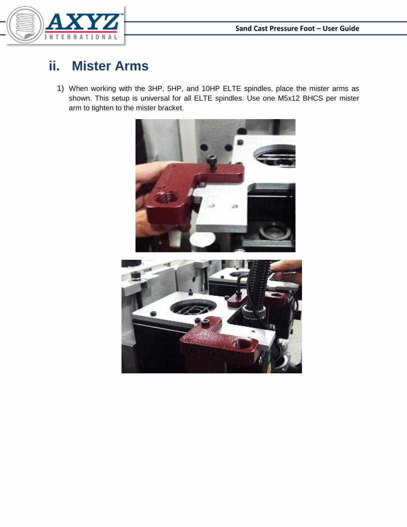
1) When working with the 3HP, 5HP, and 10HP ELTE spindles, place the mister arms as
shown. This setup is universal for all ELTE spindles. Use one M5x12 BHCS per mister
arm to tighten to the mister bracket.
Sand Cast Pressure Foot – User Guide
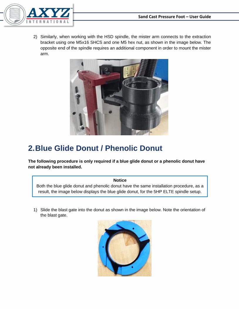
2) Similarly, when working with the HSD spindle, the mister arm connects to the extraction
bracket using one M5x16 SHCS and one M5 hex nut, as shown in the image below. The
opposite end of the spindle requires an additional component in order to mount the mister
arm.
2. Blue Glide Donut / Phenolic Donut
The following procedure is only required if a blue glide donut or a phenolic donut have
not already been installed.
1) Slide the blast gate into the donut as shown in the image below. Note the orientation of
the blast gate.
Notice
Both the blue glide donut and phenolic donut have the same installation procedure, as a
result, the image below displays the blue glide donut, for the 5HP ELTE spindle setup.
Sand Cast Pressure Foot – User Guide
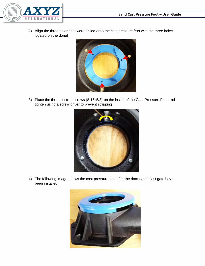
2) Align the three holes that were drilled onto the cast pressure feet with the three holes
located on the donut
3) Place the three custom screws (8-16x5/8) on the inside of the Cast Pressure Foot and
tighten using a screw driver to prevent stripping
4) The following image shows the cast pressure foot after the donut and blast gate have
been installed

Sand Cast Pressure Foot – User Guide
3. Installing Modified Bellow Seal
1) Align the tabs on the bottom plate of the bellow seal with those on the Cast Pressure
Foot, marked with red arrows in the drawings below.
2) Twist the bellow in a clockwise direction in order to lock it in place in the Cast Pressure
Foot.

Sand Cast Pressure Foot – User Guide
4. Installing Cold Air Gun
3) Obtain the cold gun mounting assembly. This assembly should contain three parts.
4) Slide the cold air gun into the mounting jig through the top (the face with the two socket
head screws) and tighten the screws as shown. Repeat this step for the second screw.
5) Align the holes on the pressure foot and the cold air gun. The cold air gun mounting
assembly rests on the top face of the cast pressure foot.
Notice: The cold air gun can be located on either end of the Cast Pressure Foot. The
orientation depends on each individual table.

Sand Cast Pressure Foot – User Guide
6) Tighten the cold air gun mounting assembly to the cast pressure foot through the
underside of the Cast Pressure Foot using two M6 button head screws, as shown in the
image below.
7) Wrap the tube around the back of the Cast Pressure Foot and screw the elbow fitting into
the center tapped hole.
Sand Cast Pressure Foot – User Guide
TESTING AND TROUBLESHOOTING
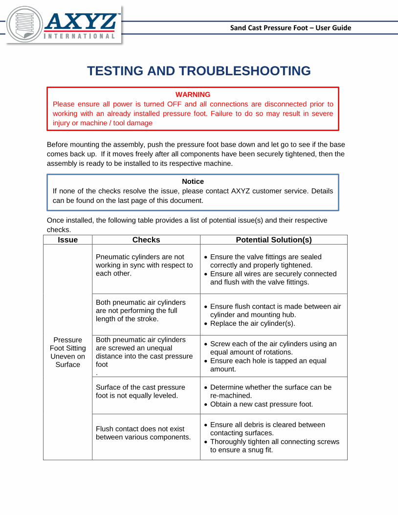
Before mounting the assembly, push the pressure foot base down and let go to see if the base
comes back up. If it moves freely after all components have been securely tightened, then the
assembly is ready to be installed to its respective machine.
Once installed, the following table provides a list of potential issue(s) and their respective
checks.
Issue Checks Potential Solution(s)
Pressure Foot Sitting Uneven on
Surface
Pneumatic cylinders are not working in sync with respect to each other.
Ensure the valve fittings are sealed correctly and properly tightened.
Ensure all wires are securely connected and flush with the valve fittings.
Both pneumatic air cylinders are not performing the full length of the stroke.
Ensure flush contact is made between air cylinder and mounting hub.
Replace the air cylinder(s).
Both pneumatic air cylinders are screwed an unequal distance into the cast pressure foot .
Screw each of the air cylinders using an equal amount of rotations.
Ensure each hole is tapped an equal amount.
Surface of the cast pressure foot is not equally leveled.
Determine whether the surface can be re-machined.
Obtain a new cast pressure foot.
Flush contact does not exist between various components.
Ensure all debris is cleared between contacting surfaces.
Thoroughly tighten all connecting screws to ensure a snug fit.
WARNING
Please ensure all power is turned OFF and all connections are disconnected prior to
working with an already installed pressure foot. Failure to do so may result in severe
injury or machine / tool damage
Notice
If none of the checks resolve the issue, please contact AXYZ customer service. Details
can be found on the last page of this document.
Sand Cast Pressure Foot – User Guide
Page | 26

Sand Cast Pressure Foot – User Guide
Sand Cast Pressure Foot – User Guide
Page | 28
PURCHASE INQUIRY AND CUSTOMER SERVICE
BURLINGTON OFFICE:
5330 South Service Road
Burlington, ON, L7L 5L1
Phone: 1-800-361-3408
Toll Free: 1-800-361-3408
CINCINNATI OFFICE:
2844 East Kemper Road
Cincinnati, OH, 45241
Phone: 513-771-7444
Toll Free: 1-800-527-9670
TELFORD OFFICE:
Telford 54 Business Park
Nedge Hill
Telford, England, TF3 3AL
Phone: 44-1952-291600
BANGLORE OFFICE:
Ground Floor, “RUKMINI PLAZA”
No. 1047, 20th Main, 5th Block, Rajajinagar
Bangalore, India, 560 010
Phone: 91-80-2314-6628
KATOWICE OFFICE:
Ul. Oswobodzenia 1
40-403 Katowice, Poland
Phone: +48-32-259-75-50
Contact by EMAIL:
Website / Social Media:
www.axyz.com | www.cncroutershop.com
Top Related