


Languages
Pages
Legal


2. THREAD GAUGES
CHECK PRODUCT
CHECK REFERENCE
WORKING GAUGES-least accurateINSPECTION GAUGESMASTER GAUGES-most accurate
By suitably designing the gauges it is possible to provide a limit gauging system which will control the complex dimension of the thread within the limits laid down by its specifications.
Need for limit gauges

The wear takes place more rapidly in screw thread gauges than in plain gauges. It is not uncommon for a hardened ring thread gauge to wear from 0.025 mm to 0.075 mm during a few days of operation. The gauge tolerance has to be adjusted in such a way as to take into account the wear allowance. This reduces the work tolerance by an amount that must be allowed for wear in full form ring gauge. This allowance for wear is overcome in Caliper gauges to a great extent. The allowance recommended by B.S.I, for wear on generally used solid ring and plug gauges is 0.05 mm. Therefore, frequent checking of solid pattern gauges is necessary.
Gauge wear:

3) Gages:
► Plug gages:(a) Plug gage for checking size or diameter of internally threaded part.(b) Plug gage for checking taper of internally threaded part.(c) Ring gage for checking size or diameter of externally threaded part.
Eng/ Mohammed Abd Elghany. 2nd I.E.D 3

3) Gages:
► Ring gages:
(a) The Metric Trapezoidal Ring Gage.
(b) American Standard Adjustable Ring Gage.
Eng/ Mohammed Abd Elghany. 2nd I.E.D 4

3) Gages:
► Snap gage:
Eng/ Mohammed Abd Elghany. 2nd I.E.D 5

Forms of thread gauges
Plug screw gauges:
For gauging nuts or internal threads it is obvious that full form plug gauge made accurately to minimum dimensions of internal thread will ensure that all dimensions of the thread are not less than that minimum if it will assemble with the thread.
A plain NO GO gauge is required for
Major DiameterMinor DiameterEffective Diameter

Form of threads for NO GO effective diameter gauge is shown in Fig.
The gauges are made up of special quality gauge steel, hardened and seasoned before the threads are grooved and finally tapped to dimension.
How gauges are manufactured?


For gauging parallel external screw threads, minimum of following 3 gauges are recommended.(i) a plain caliper gauge with gauging features to check the tolerance on the major diameter.(ii) a screw caliper gauge with full form gauging features to check the maximum effective diameter, or a screw ring gauge.(iii) A screw caliper gauge with special gauging features to operate slowly on the flanks of the thread, to check the minimum effective diameter.
For gauging parallel internal screw threads, following 3 gauges are recommended.
(i) GO and NO GO plug gauges to check the tolerance on the minor diameter.
(ii) a GO screw plug gauge to check the minimum effective diameter. (iii) a NO GO screw plug gauge to check the maximum effective diameter.

Ring screw gauges
For production gauging of bolts the equivalent mating surface of the bolt threads is known as a ring gauge.
The NO GO ring gauge is truncated on its minor diameter and cleared on its major diameter as shown in Fig. below.
The legend stamped on the ring should give size and pitch, for example, 7/16-20 NF means the workpiece should be of 7/16" outside or major diameter having 20 threads per inch (National fine threads series)
Sometimes class of fit also appears on the ring.

A thread ring cannot ordinarily be used to analyse the individual errors present in a screw. If the pitch diameter is over-size the ring will not engage : of course neither will it turn on an over-size major diameter. If the minor diameter is off (i.e., the screw whose roots are filled with dirt, or made from worn die or lathe tool) the gauge will bind. Excessive screw thread lead errors, like taper will ordinarily be detected after a few turns of ring gauge. Where very fine threads are being gauged, care must be exercised not to force the threads of the ring gauge on screw.
How to analyze the errors??

Caliper Gauges.
With 2 set of anvils
The front anvils have the full thread form cut on them and are set at distance apart as to accept the screws below the upper size limit(GO anvils of the gauge)
If the screw passes through the front go anvils, it reaches near NOGO anvils. There is no anvils test the effective diameter, the tooth formed on these anvils is cleared off at root and truncated at crest

Taylor's principle applied to screw thread gauges
It has already been indicated that effect of errors of pitch and flank angle is to bring about a virtual increase in the effective diameter in case of external threads and a decrease in effective diameter in case of internal threads. Accordingly Taylor's principle can be applied to threads also. It may be remembered that according to Taylor's principle, a GO gauge should check both geometric features and size and thus be of full form, whereas NO GO gauge should check only one dimension. In line with this, GO gauge is made of full form to the full length of thread to the maximum diameter of thread. If NO GO thread gauge is also made of full form, then the virtual reduction in effective diameter due to pitch errors may give misleading results. To obviate this difficulty, and to account for Taylor's principle, NO GO gauges for the threads are made to check for major diameter and the effective diameter which is not influenced by the errors in pitch or form of the thread.

GUARD EXTENSION ON PLUG GAUGES
METHOD FOR PREVENTING FEATHER EDGES

Tolerance for Screw Thread Gauges and Screw Threads
Effective diameter
The effective diameter tolerance must take into consideration the three variables (i) the major diameter; (ii) the length of thread engagement; (iii) the pitch.
Tolerance on effective diameter:
pcLbDa 3
D-major diamterL-length of engagementp -pitch
The value of these constants according to British Standard Specifications for Whitworth threads are a=0.002,b=0.003 c=0.005 for medium fit

The specifications provide for three grades of fits, (a) close, (b) medium, (c) free.
The basic formula gives effective diameter tolerance for medium fit. Close fit tolerances are two-thirds of free fit, and free fit tolerance is one and a half times that of medium fit. This results in tolerance increasing by 50% each time from close-medium-free fit.Close fit. This applies to screw requiring a fine snug fit.Medium fit. Suitable for better class of ordinary interchangeable screw threads. Free fit. Suitable for bulk of screw threads of ordinary commercial quality. Major Diameter. Its tolerance is given by expression :
ptolerancediamterEffective 013.0
This is applicable for all grades of fits(external threads)
Minor diameter:
for medium and free fit.ptolerancediamterEffective 02.0
for close fit

Tolerance on internal threads(on nut)
a) 26 TPI finer -0.2p+0.004’’b) 22 TPI and 24TPI = 0.2p+0.005’’c) 20 TPI and coarser = 0.2p+0.007’’
# Determine the limiting dimensions for a bolt and nut ¾’’ B.S.F(medium fit)
inch 0.0058
0.00140.00260.0018 12
1005.075.0003.00.750.002
005.0003.0D0.002
:olerancediameter t Effective b)
inch 0.6434
12
164.020.75
20.75diameter core
0.75Diameter Full :sizes a)basic
3
3
''
''
''
pL
Depth

inch 0.0236
0.0070.2p
coarser and 20TPIFor
threads)(internalnut On ii)
inch 0.0116
02.0lerancediamter to Effective
fit medium and threads)rnalbolts(extei)For
lerancediamter tominor d)
inch 0.0087
p0.01 lerancediamter to Effective
threads)rnalbolts(extefor
lerancediamter toc)Major
''
p
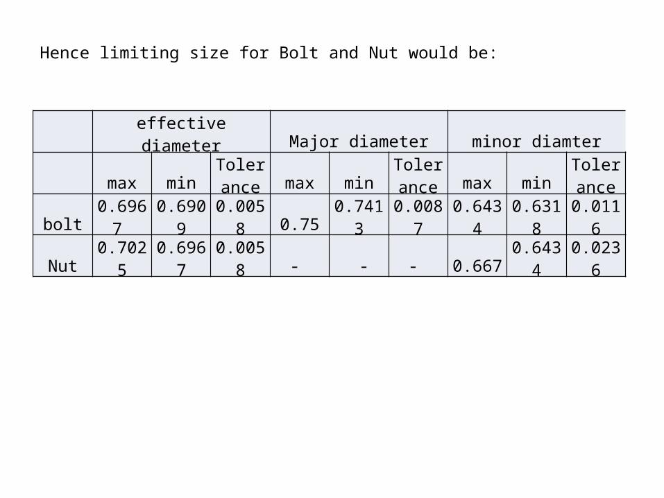
Hence limiting size for Bolt and Nut would be:
effective diameter Major diameter minor diamter
max minToleranc
e max minToleranc
e max minToleranc
e
bolt 0.6967 0.6909 0.0058 0.75 0.7413 0.0087 0.6434 0.6318 0.0116
Nut 0.7025 0.6967 0.0058 - - - 0.667 0.6434 0.0236

Adjustable Thread Gauges (Metrology)
The fixed or solid pattern plug and ring screw thread gauges possess certain disadvantages that may be enumerated briefly as follows:
Gauge wear: This wear takes place more rapidly in screw thread gauges than in plain gauges. It is not uncommon for hardened ring—thread gauge to wear from 0.02 mm to 0.03 mm during a few days use. When full form GO and effective diameter NOT GO ring gauges are used, manufacturing tolerance of work is reduced by amount that must be allowed for wear in the full form ring gauges.
Gauge making tolerances. Solid gauges, being unadjustable for wear, their use reduces considerably the tolerance or limit of accuracy within which the work must actually be made, thus increasing the cost of manufacture.
Possible Inaccuracy. Owing to wear effects, which in time may take up the full amount of tolerance allowed, there is always the risk of a gauge being used beyond its designed capacity with the result that the work checked with the gauge will be inaccurate ; frequent checking of screw thread gauges is necessary in order to obviate this effect.

The Wickman
adjustable thread gauge shown in Fig below can be used for inspecting both right and left hand threads. It is adjustable to 0.002 mm and will test for out of roundness or eccentricity. It can be sealed after adjustment and is temper proof.
The principle of the Wickman thread gauging system is to ensure truly interchangeable thread work of sound mechanical strength by controlling within the prescribed limits, the major, minor and effective diameters
Notes on working : next page
To set the gauge, the anvils are first adjusted by means of the adjusting screws until the setting of master gauges held between them is just sufficiently right to support the weight of the gauge. If the locking screws are tightened by means of a special key supplied then the ball will be slightly compressed; their elasticity enables the setting gauge to be gripped or loosened alternately. An intermediate adjustment, where the setting gauges can just slide through the anvils is the desirable setting. After adjustment, a monogram lead seal can be fixed over the adjusting screws. The frame of the gauge is of cast iron with specially selected characteristics to ensure that it will break rather than take a permanent set in the event of an accident. The anvils are of hardened tool steel and made sliding fit in their holder. Hardened abutments fixed solidly to the frame prevent the anvils from turning or tilting. The gauges are made to suit all standard screw thread forms. The principle of the Wickman thread gauging system is to ensure truly interchangeable thread work of sound mechanical strength by controlling within the prescribed limits, the major, minor and effective diameters. As mentioned previously, the effective dia. is virtually increased by errors of pitch and angle so it must not be too large. For this reason the 'front' or 'GO' portion of the anvil is provided with a full form of thread of sufficient width to cover the engagement of the screw; it is set to the nominal diameter. The rear anvil is of specially truncated form and consists of a few threads only, in order that contact may be made only on the central portion of the flanks of the thread and that no effects of pitch error are taken into account. In this way, the gauge certifies that the effective dia. is not too small. The threads on the anvils are relieved so that there is no interference with the helix of the thread being inspected ; thus inspection takes place on the axial line of the thread, where the true thread is located. As there is no interference with the helix angle, the same gauge can be used for both right and left hand threads.

Gauging of Taps

Nominal Diameters Pitches
1st Choice 2nd Choice 3rd Choice Coarse Fine
20 18 17 2.5 2.5 — 1.5 1 2 1.5 1 2 1.5 1
24 22 25 2.5 3 2 1.5 1 2 1.5 1 2 1.5
Diameter and pitch combinations for ISO metric thread
The standard values of major diameters and the pitches for coarse and fine threads (ISO Metric screw threads) are given below :
Minor dia
Coarse Threads Minor
dia
Coarse Thread Fine Thread
Pitch Minor dia Pitch Minor
dia Pitch Minor dia
1.6 0.35 1.22 8 1.25 6.65 1.00 6.92
2 0.4 1.57 10 1.5 8.38 1.25 8.65
2.5 0.45 2.01 12 1.75 10.11 1.25 10.65
3 0.5 2.46 16 2.0 13.83 1.50 14.38
4 0.7 3.24 20 2.5 17.29 1.50 18.38
5 0.8 4.13 24 3.0 20.75 2.00 21.83
6 1.0 4.92 30 3.5 26.21 2.00 27.83
36 4.0 31.67 3.00 32.75

M 33 x 2;M 20?
Design profile:
Basic dimensions for design profiles for ISO Metric screw threads are given below. Their exact values in tabular form for threads in the diameter range of 1 to 300 mm have been indicated in IS : 4218 (Part III)—1976. The standard symbols for denoting the various important quantities are :

Gauges for Work piece External Threads and their Check Plugs and Setting PlugsAccording to IS : 2334—1975, following gauges are prescribed
(a) Solid GO screw ring gauge, (b) Adjustable GO screw ring gauge.(c) Check plugs (GO and NO GO) for new solid GO screw ring gauge.(d) Setting plug for adjustable GO screw gauge.(e) Wear check plug for solid or adjustable GO screw ring gauge,
(f), GO screw caliper gauge.(g) Setting plug for GO screw caliper gauge, (h) NO GO screw caliper gauge. (i) Setting plug for NO GO screw caliper gauge, (k) Solid NO GO screw ring gauge. (m) Adjustable NO GO screw ring gauge.(n) Check plugs (GO and NO GO) for new solid NO GO screw ring gauge.(0) Setting plug for adjustable NO GO screw ring gauge.(p) Wear check plug for solid or adjustable NO GO screw ring gauge.(q) Plain gauge for major dia (ring or caliper gauges).Gauges for Workpiece Internal Threads,(a) GO Screw plug gauge, (b) NO GO screw plug gauge.(c) Plain gauges for minor diameter (plug gauges).It is not essential that all these gauges have to be used but GO and NO GO limits should be ensured by proper gauges for every piece.
Refer text book for more information

Tolerance Zones for Pitch Diameter of Screw Gauges for External Thread.
For the female threads the letter is upper class and for the male threads the letter is lower class. Therefore H6 is a tolerance grade for a female(Internal ) thread and g6 is a tolerance grade for a male (External ) thread. The tolerance band positions relative to the basic zero size are illustrated in the figure below

Threads Pitch Gauges for ISO metric screw thread
The pitch range 0.25 to 6.0 mm are made in the form of 24 blades (made of suitable tool steel sheet and 0.5 mm thick), 23 for checking the pitches and one having an ISO profile of 60°. All these blades are assembled in a protective sheath. All the blades are suitably hardened and tempered to a hardness of 540 HV and properly finished and sharp edges removed.
Top Related