


Languages
Pages
Legal


2/2009
The Arup Journal
2 The Arup Journal 2/2009
2 The design of bridges
Sir Ove Arup3 Foreword Jørgen Nissen
14 Diversity and change: Music, architecture, design, and enabling the future
John Wallace
20 Westlink/M1, Northern Ireland
Dom Ainger John Border Chris Caves Paola Dalla Valle Chris Furneaux Tim Gammons John Griffiths Deepak Jayaram Ray Kendal Ronnie Palmer Alan Phear Andy Ross Guy Stabler
32 Arup Japan: Design in an earthquake zone
Shigeru Hikone Mitsuhiro Kanada Ryota Kidokoro Masato Minami Ikuhide Shibata
34 Mind-Body Column, Osaka
38 Toyota Stadium, Toyota City, Aichi
42 Maison Hermès, Tokyo
45 NTT DoCoMo tower, Osaka
49 Sony City, Tokyo
52 Nicolas G Hayek Center, Tokyo
55 MODE GAKUEN Cocoon Tower, Tokyo
Contents
3The Arup Journal 2/2009
Sir Ove Arup: The design of bridges
*Jørgen Nissen joined Arup in 1962, at first designing shell structures. He was one of the prize-winning Calder Bridge competition team and later in attendance at the birth of the Highways and Bridges group. He was made a director in 1977, a main board director in 1984 and a trustee in 1992. He retired from the board in 1999 and as a trustee in 2004. He is now a consultant to Arup. Throughout his career Jørgen has maintained his interest in bridge design. Of his many bridge projects his favourites are, from the beginning, the Bishopthorpe and Berry Lane bridges in England, in the middle the Kylesku Bridge in Scotland, and at the end the Øresund Bridge between Denmark and Sweden.
ForewordJørgen Nissen*
Ove Arup (1895-1988) once said in a BBC interview
that the two structures that had given him most
satisfaction were the Highpoint flats in North London
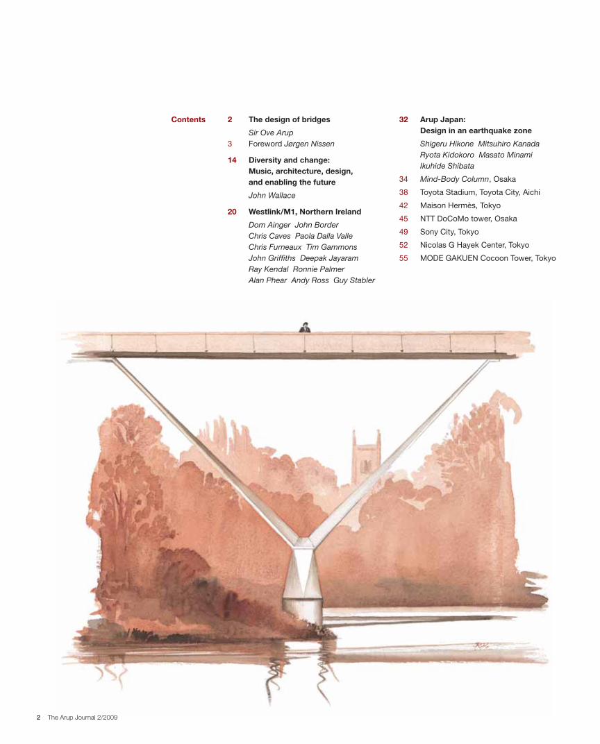
(1935) and the Kingsgate footbridge, Durham, Yorkshire
(1963), as “both are rather perfect examples of the
complete integration of architecture, structure and
method of construction”.
But before Kingsgate Ove had designed other bridges.
Although they were for real none was built, for reasons
unconnected with their design, but he wrote about
them. The article that begins overleaf appeared in the
Arup London Newsletter, nos 21 and 22, February and
April 1964, though it was written a few years earlier
so that Kingsgate only comes in with a few final lines,
almost as an afterthought.
In 1961 Ove had shown sketches of some of his bridge
designs to his CIBA friend the Italian architect Ernesto
Rogers (1909-1969), who was then editor of the
architecture magazine Casabella. The article “Cinque ponti” duly appeared in June 1961. Ove changed it
slightly two years later, and a shortened version, “Trois projets de ponts”, appeared in the October/November
1963 issue of L’Architecture d’Aujourd’hui. The London Newsletter editor, Rosemary Devine, reverted to the
longer English original for the Arup publication (but to a
then very small internal audience).
It is a fascinating article, well worth studying even now
almost 50 years later, and not only by bridge engineers.
In it Ove lucidly describes what he meant by what he
would later call “total architecture” – which, whatever
we call it now, is very much what we are about.
He wrote extensively about “total architecture”
throughout his career, but usually in the abstract,
almost philosophically. Here, uniquely in his writings,
he is addressing the subject in specific contexts, with
real if unbuilt examples, revealing step-by-step how his
thoughts progressed.
He says it all at the start, emphasising that he is writing
about bridges – “… a more rewarding field for the study
of unity between architecture and structure. A bridge is
architecture with a clear and simply formulated function.
All one has to worry about is the stability, durability,
cost, and appearance.” And as for appearance:
“there will always remain a number of more or less
arbitrary decisions, which have to be made on purely
aesthetic or sculptural grounds. I suggest, however,
that the best result is obtained if there are very few of
such arbitrary decisions to be made, in other words,
if decisions affecting proportion and form at the same
time make structural and constructional sense”.
In spite of writing for an audience of architects – or
perhaps because of it – he did not offer any thoughts
on how these decisions should be taken. He did not
need to. He was writing about the engineering. In
the earlier Casabella version he had included a small
footbridge at Bowring Park, St Johns, Newfoundland,
but he almost apologises for it at the end of the
paper: “it does not really belong in this series because
the method of construction is not in any way out of
the ordinary and in fact, the whole object is small
and insignificant and presents no structural and
constructional difficulties. But the appearance was
important – it always should be anyhow. This is
therefore a case of satisfying function and structure
in a pleasing and neat manner – construction is of
lesser importance.”
And when he refers to Kingsgate at the end he adds:
“Although appearance was of major importance in this
case, the form was largely influenced by structural and
constructional considerations”. He did work with the
architect Yuzo Mikami on this bridge and it is a great
pity that he could not include a full account here and so
close the argument.
A few years later, in 1971, Ove was asked by the
Institution of Civil Engineers to advise on “how to
improve the appearance of engineering structures…
if architects are not to muscle in on the Engineer’s
domain” (sic!)… and “please write a paper which will
teach engineers how to design beautiful and efficient
structures”. True to character, he wrote a fairly long
paper explaining why he could not write such a paper,
concluding: “you cannot make rules or principles for
what is beautiful, but you may be able to learn by
examples of good design – by studying it in statu nascendi”. He does just that in this article.
All four bridges were to be built over water and
therefore called for particular engineering expertise.
Ove had that expertise; he had been chief designer for
contractors specialising in marine structures for nearly
20 years: “We were designers and contractors in one,
design and construction were naturally integrated.
Now the bulk of designers are mostly unacquainted
with the problems on site.”
The construction methods he proposes are complex,
but as ever Ove explains them in simple direct
language. He is aware of the danger of writing ex post but he writes about it as it is, not leaving out
ideas that had to be aborted and only including the
successful ones. The construction methods are all quite
sophisticated and would have been innovative at the
time but feasible. His partner Geoffrey Wood (1911-
2007), who had a great deal of experience of working
in Africa, did argue that the Ghana bridges required
technology not then available in Africa. But Ove insisted
that they had been “designed down to the last detail”.
So they had, but then maybe the local contractors did
not yet have an Ove.
Would we do the same today? We might.
But technology has moved on; we now have at our
disposal stronger and more durable materials, more
precise controls and better methods of analysis and
forecasting, more sophisticated construction methods,
etc. The limits of what we can now do have expanded.
And society has greater expectations; environmental
and social issues are significant and Ove’s “more or
less arbitrary decisions” now weigh heavier in the
balance sheet.
He would have approved. His approach is as relevant
now as it ever was, even if the input to the process and
therefore the outcomes may be different. It is a pity that
these four bridges were never built, but he did at least
leave us the best: the delightful Kingsgate bridge and
our approach to “holistic design”.
After the article was written, the Ministry of Transport,
then England’s main client for bridges, announced its
first-ever design competition, for the Calder Bridge in
Yorkshire. 110 designs were submitted, five of them
from Arup (London Newsletters 19-22, January-
May 1964). A team from Povl Ahm’s group including
Yuzo Mikami as architect won a special prize. This
led directly to the award in 1965 of our first bridge
project by the Ministry, the Gateshead Viaduct, and the
Highways and Bridge group in London was born.
Ove took an interest – and sometimes more than
an interest – in some of our subsequent bridges,
particularly the Jesmond Dene Bridge in Newcastle,
close to his birthplace. The design was almost ready for
tender when the project was cancelled following public
pressure not to demolish the existing wrought iron
Armstrong Bridge built in 1878. This is in fact a striking
bridge and is now listed.
Kingsgate footbridge, Durham.
4 The Arup Journal 2/2009
about, then, is the stability, durability, cost, and appearance. Or to put it in another
way, structure, method of construction, and architecture.
It is, of course, the architectural past which for the engineers may be the most
difficult to come to grips with, and this explains my interest in exploring the issue.
Architectural theories, I am afraid, do not help much. Unity, harmony, balance,
proportion, scale, pattern, truth, structural honesty, fitness for purpose, economy of
materials; all these guiding principles are much too general, and can all be violated
with impunity in particular cases. They give practically no guidance to the designer
who has to resolve an alternative on the drawing board. Fortunately bridge design
is fairly immune from infection by warring and ephemeral architectural issues.
It is generally accepted that to impose a preconceived “style” would be out of place.
This leaves us basically with a structure with certain sculptural qualities. But this is not
the same as a piece of sculpture with certain structural and spatial qualities enabling it
to carry traffic from A to B. If an architectural critic looks at the finished result he may
be tempted to judge it from the latter point of view. He has a right to do so, of course,
but it would be like judging a car by its appearance only. To judge the quality of a
bridge – the whole bridge and nothing but the bridge – one should not only appraise
its form, but should understand why it has that form.
This brings me to the crux of my argument, which is that to study architecture –
I am talking about bridges, but suspect that it applies to all architecture – one should
study it in statu nascendi.* One should be privy to the working of the minds of the
creators. Creating architecture – good or bad – consists of making a great number
of choices. One should get to know what these choices were, what was rejected
as well as what was adopted, and why. If one selected as example designs of
acknowledged merit – and there is much more agreement about what is good, once
it has been created, than about architectural theory – then one would come nearer
to an understanding of how good architecture was produced and one might perhaps
even get an inkling of what good architecture was. One would derive a benefit akin
to that accruing to the pupil who watches his master at work. It would serve the dual
purpose of exploring the nature of good architecture and of teaching the making of it.
It would be nice to think that that this was generally conceded and that henceforth
we would be spared the tedious descriptions of what the work looked like, how many
tons of cement and acres of glass were used, how the contract was administered
and so on, and that we instead would witness through information “straight from the
horse’s mouth”, the exciting battle going on in the designer’s mind to find the right
answer amongst the scores of possible solutions. But I am afraid these are pipe
dreams, and that for several very good reasons.
The main reason is this, that it is extremely difficult to get hold of what exactly
happens during the largely intuitive process of designing. The material would at any
rate have to be edited and drastically reduced. It is also difficult to remember unless
immediately recorded. Designers are not authors; they are bent on designing, not on
recording. When much later, a reconstruction of the process is attempted, the result
is probably a rationalisation more Dichtung than Wahrheit**. And then in order even to
attempt to describe the design process to the reader, it is necessary that he should
understand the problem as it presents itself to the designer. The latter will have spent
some time and effort getting acquainted with the problem as it relates to the site and
other conditions, and only when it has been thoroughly absorbed into his system will
be able to survey the field of three-dimensional possibilities in his head.
This article is about the design of bridges, and tries
to show why in a number of cases certain designs
were chosen, and how they were developed. That
most of these bridges will probably never be built is
regrettable but does not defeat my main purpose,
which is to probe into the nature of architecture
by showing how in the case of bridge design the
architectural form results mainly from the choice
of structure and the method of construction.
I say mainly, because there will always remain a
number of more or less arbitrary decisions about
proportions or detail design which do not greatly
affect economy or functional efficiency, and which
have to be made on purely aesthetic or sculptural
grounds. I suggest, however, that the best result
is obtained if there are very few of such arbitrary
decisions to be made, in other words, if decisions
affecting proportion and form at the same time make
structural and constructional sense.
When everything thus “comes naturally”, there will
be the greatest possible unity between architecture
and structure – they will in fact be one and the same
thing, which is as it should be. I know that this kind
of unity is not always possible, and that it can be
perfectly justified to do violence to the structure or to
add to the difficulties of construction in the interest of
architectural values, but most people agree that such
unity is worthwhile striving for. As is well known, what
in the end “comes naturally” is the most difficult thing
to attain. It has the best chance of emerging if one
mind controls the design process. That is why the
great bridges are created by engineers with a feeling
for form, but thinking mainly in engineering terms.
Unity between architecture and structure, or
perhaps rather “Unity” in general, has since Aristotle
been valued as a mark of great architecture.
However, in the case of buildings filled with technical
equipment and housing a multitude of human
activities – as for instance a teaching hospital – such
unity is difficult to obtain or even define. The needs
to be harmonised are multifarious and perhaps even
conflicting, and structure anyhow comes rather low
on the list of priorities. That is why bridges and large
engineering structures seem to me a more rewarding
field for the study of architectural unity. That a bridge
is a form of architecture will probably be conceded;
in fact it can have a very powerful architectural
impact. But it is architecture with a clear and simply
formulated function: to carry traffic of a certain kind
from one place to another. All one has to worry
“That a bridge is a form of architecture will probably be conceded... in fact it can have a very powerful architectural impact.”
The design of bridgesSir Ove Arup
* “In its original form”. **From Goethe’s autobiography Aus meinem Leben: Dichtung und Wahrheit (“From my Life: Poetry and Truth”).

5The Arup Journal 2/2009
Considering the method of construction, however,
it was very soon found that to provide a temporary
staging for the whole bridge would be far too
expensive. The best method seemed to be to drive
piles from a floating plant for the construction of the
piers and then cantilever both ways from these piers,
delivering all the materials or precast units to these
piers by barge (Fig 1). This would not be easy,
considering the depth of water and the skewness of
the pier; at the least it would require very heavy and
expensive piers. It would obviously facilitate matters
enormously if each of the two piers was replaced by
two narrow piers relatively close together (Fig 2).
These two twin piers would then form natural
harbours for supplies by barge and would, when
connected, form a stable base from which to
cantilever in both directions. Further, it would then be
possible to arrange floating spans connecting the
bridge with the shore, thus diminishing the height of
construction over land, and solving the problem of
temperature changes.
However, there was still the skewness to consider.
The narrow piers would have to follow the direction
of the current, forming an angle of 60˚ with the
centreline of the bridge (Fig 3). If we, in order to
preserve the symmetry and the logic of the system,
were to cut the floating spans on the skew as well
(Fig 4), all sorts of problems would arise. The system
would work if the bridge consisted of parallel strips,
but that would be wildly uneconomic because each
What he can then see in a flash will need a lot of explanations and 3-D sketches or
models to put across to a reader.
I am afraid, therefore, that this statu nascendi business will have to be dropped,
at least if taken too literally. But I still think that the main idea has validity, and
that designers could make a contribution to informed criticism if they could bring
themselves to give an account of the path followed – including some of the blind
alleys – to reach a particular solution.
This then, is what I am going to attempt, but I am immediately up against two
difficulties. One is lack of time and space which will make my effort very sketchy in
any case. The other, more serious, is, that in the nature of things I can only talk about
my own experiences. What we really want is an eye-witness account of how great
architecture is produced, and unfortunately I am far from being a great architect.
My only hope is that my example will inspire someone better qualified to make
a more valuable contribution on these lines.
Perth Narrows Bridge
The first design, for a bridge over the Narrows at Perth, Australia, never got further
than an early sketch stage, but the fundamental decisions about how to build the
bridge had been taken and, as will be seen, these decisions, logically applied, resulted
in a bridge of a somewhat unusual form.
The task, as presented to us by the clients at the time, was to build a low road
bridge 92ft wide and 1300ft long – of which 900ft were over water – between the
mainland and a large island. The special feature of this bridge was its skewness –
the line of the bridge formed an angle of 60˚ with the channel it had to span, and
consequently with the current. The clients at one time expressed the hope of
spanning the bridge in one span, but that could only be done by having the main
structure above road level – suspension bridge – and that was not considered
desirable for other reasons – landscape. The best that could be hoped for with the
construction height available was three spans: a long middle span with two cantilevers
and a floating span, and two shore spans.
1.
2.
3.
4.
6 The Arup Journal 2/2009
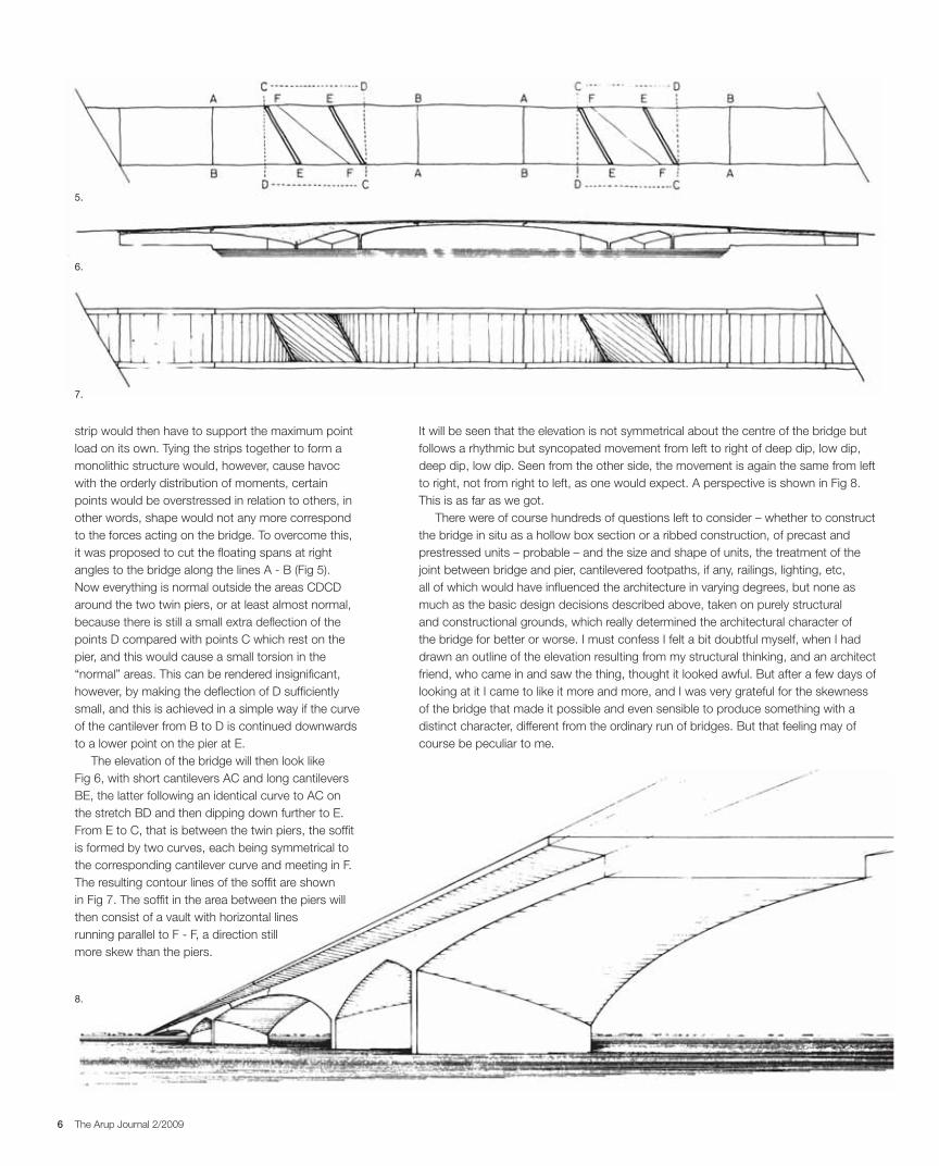
It will be seen that the elevation is not symmetrical about the centre of the bridge but
follows a rhythmic but syncopated movement from left to right of deep dip, low dip,
deep dip, low dip. Seen from the other side, the movement is again the same from left
to right, not from right to left, as one would expect. A perspective is shown in Fig 8.
This is as far as we got.
There were of course hundreds of questions left to consider – whether to construct
the bridge in situ as a hollow box section or a ribbed construction, of precast and
prestressed units – probable – and the size and shape of units, the treatment of the
joint between bridge and pier, cantilevered footpaths, if any, railings, lighting, etc,
all of which would have influenced the architecture in varying degrees, but none as
much as the basic design decisions described above, taken on purely structural
and constructional grounds, which really determined the architectural character of
the bridge for better or worse. I must confess I felt a bit doubtful myself, when I had
drawn an outline of the elevation resulting from my structural thinking, and an architect
friend, who came in and saw the thing, thought it looked awful. But after a few days of
looking at it I came to like it more and more, and I was very grateful for the skewness
of the bridge that made it possible and even sensible to produce something with a
distinct character, different from the ordinary run of bridges. But that feeling may of
course be peculiar to me.
strip would then have to support the maximum point
load on its own. Tying the strips together to form a
monolithic structure would, however, cause havoc
with the orderly distribution of moments, certain
points would be overstressed in relation to others, in
other words, shape would not any more correspond
to the forces acting on the bridge. To overcome this,
it was proposed to cut the floating spans at right
angles to the bridge along the lines A - B (Fig 5).
Now everything is normal outside the areas CDCD
around the two twin piers, or at least almost normal,
because there is still a small extra deflection of the
points D compared with points C which rest on the
pier, and this would cause a small torsion in the
“normal” areas. This can be rendered insignificant,
however, by making the deflection of D sufficiently
small, and this is achieved in a simple way if the curve
of the cantilever from B to D is continued downwards
to a lower point on the pier at E.
The elevation of the bridge will then look like
Fig 6, with short cantilevers AC and long cantilevers
BE, the latter following an identical curve to AC on
the stretch BD and then dipping down further to E.
From E to C, that is between the twin piers, the soffit
is formed by two curves, each being symmetrical to
the corresponding cantilever curve and meeting in F.
The resulting contour lines of the soffit are shown
in Fig 7. The soffit in the area between the piers will
then consist of a vault with horizontal lines
running parallel to F - F, a direction still
more skew than the piers.
5.
6.
7.
8.
7The Arup Journal 2/2009
exactly in that order. When you are designing,
the mind is let loose amongst a lot of possible
combinations of statical systems, methods of
construction, until an idea emerges for closer
examination. Anyhow the idea emerged, based on
the preferred statical system, to form the bridge
of floating units - which I will call “barges” - which
could be completely finished with paving, lighting,
railings, etc, on shore, and which could be lifted up
to their final position by making use of the supporting
structure of A-frames. If the main A-frames
supporting the barges are hinged top and bottom
by simple open hinges and the barges are pulled
towards each other, they will automatically rise from
the water at high tide to the required level, and can
be secured to the other A-frames which provide the
longitudinal stability (Fig 9).
It would take too long to describe in detail the
various problems involved in this operation, but the
forces were all calculated and the necessary plant
designed in principle. The winches and hoisting gears
were to be fixed to a temporary steel frame formed
as a pyramid, which from a couple of barges could
be transferred to each pier in turn. A floating crane
would transfer the A-frames to the piers and the
bridge barges would be guided towards each side of
the pier by temporary guides fixed to the piers.
It is obvious that the use of structural steel for the
bridge would favour these operations, as the weight
of barges, etc, would be much less. There was
actually no time to investigate a prestressed concrete
scheme as well, but had it been decided to proceed
with the construction of the bridge, this should have
been done. It would have reduced maintenance
problems - but actually these were not too bad in
the case of the steel structure, because it was to
be constructed of hollow units presenting a smooth
surface to the outside.
Actually, later a probably somewhat better way to
erect the bridge was thought of. According to this
the lifting up of the barges from the sea would take
place at the dockyard, and the whole section of
bridge resting on one pier, including A-frames but
excluding the floating spans, would be brought to
the bridge pier on two large barges or ships,
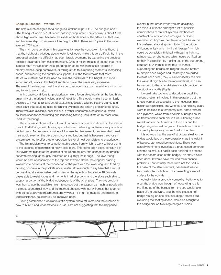
Bridge in Scotland – over the Tay
The next sketch design is for a bridge in Scotland (Figs 9-11). The bridge is about
8070ft long, of which 5510ft is over not very deep water. The roadway is about 110ft
above high water level, because the roads on both sides of the firth are at that level,
and because shipping requires a free height of 82ft. There are 11 piers in the water,
spaced 475ft apart.
The main consideration in this case was to keep the cost down. It was thought
that the height of the bridge above water level would make this very difficult, but in the
proposed design this difficulty has been largely overcome by extracting the greatest
possible advantage from this extra height. Greater height means of course that there
is more room available for the supporting structure, which makes it possible to
employ arches, deep cantilevers, or raking struts thus reducing moments, increasing
spans, and reducing the number of supports. But the fact remains that more
structural material has to be used to raise the road level to this height, and more
important still, work at this height and far out over the sea is very expensive.
The aim of the designer must therefore be to reduce this extra material to a minimum,
and to avoid work in situ.
In this case conditions for prefabrication were favourable, insofar as the length and
uniformity of the bridge involved a lot of repetition. This would make it economically
possible to invest a fair amount of capital in specially designed floating cranes and
other plant that could be used for sinking cylinders and landing prefabricated units.
There was also available, near the site, a rather underempIoyed shipyard, which
could be used for constructing and launching floating units, if structural steel were
used for the bridge.
These considerations led to a form of cantilever-construction almost on the lines of
the old Forth Bridge, with floating spans between balancing cantilevers supported on
central piers. Arches were considered, but rejected because of the one-sided thrust
they would exert on the piers during construction, but mainly because the chosen
system seemed to offer greater opportunities for almost complete shore-fabrication.
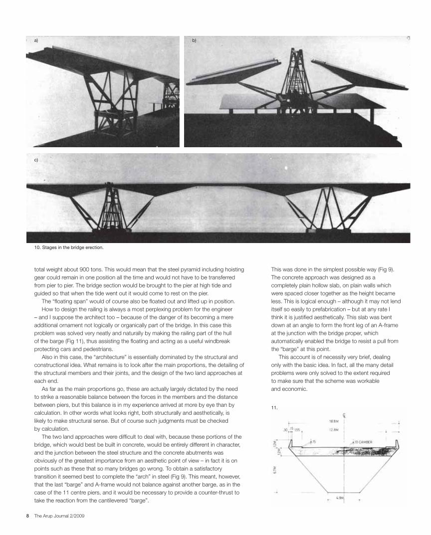
The first problem was to establish stable bases from which to work without going
to the expense of constructing heavy solid piers. This led to open piers, consisting of
four cylinders placed at the corners of an 18.5m square, and connected by precast
concrete bracing, as roughly indicated on Fig 10(a) (next page). The lower “ring”
would be cast or assembled at the top and lowered down, the diagonal bracing
lowered into pockets at the connection of the piers with the lower ring, and fixed by
pouring concrete in the pockets under water, etc – enough to say here that it would
be possible, at a reasonable cost in view of the repetition, to provide 18.5m wide
bases able to resist forces and moments in all directions, and therefore each able to
support a portion of the bridge independently of the other piers. The next problem
was then to use the available height to spread out the support as much as possible in
the most economical way, and the method chosen, with four A-frames that together
with the deck provide maximum stability with a minimum of material and minimum
wind resistance, could hardly be improved upon.
Having established a desirable static system, there still remained the question of
how to build it and what materials to use. I am not suggesting that this happened
9.
8 The Arup Journal 2/2009
This was done in the simplest possible way (Fig 9).
The concrete approach was designed as a
completely plain hollow slab, on plain walls which
were spaced closer together as the height became
less. This is logical enough – although it may not lend
itself so easily to prefabrication – but at any rate I
think it is justified aesthetically. This slab was bent
down at an angle to form the front leg of an A-frame
at the junction with the bridge proper, which
automatically enabled the bridge to resist a pull from
the “barge” at this point.
This account is of necessity very brief, dealing
only with the basic idea. In fact, all the many detail
problems were only solved to the extent required
to make sure that the scheme was workable
and economic.
total weight about 900 tons. This would mean that the steel pyramid including hoisting
gear could remain in one position all the time and would not have to be transferred
from pier to pier. The bridge section would be brought to the pier at high tide and
guided so that when the tide went out it would come to rest on the pier.
The “floating span” would of course also be floated out and lifted up in position.
How to design the railing is always a most perplexing problem for the engineer
– and I suppose the architect too – because of the danger of its becoming a mere
additional ornament not logically or organically part of the bridge. In this case this
problem was solved very neatly and naturally by making the railing part of the hull
of the barge (Fig 11), thus assisting the floating and acting as a useful windbreak
protecting cars and pedestrians.
Also in this case, the “architecture” is essentially dominated by the structural and
constructional idea. What remains is to look after the main proportions, the detailing of
the structural members and their joints, and the design of the two land approaches at
each end.
As far as the main proportions go, these are actually largely dictated by the need
to strike a reasonable balance between the forces in the members and the distance
between piers, but this balance is in my experience arrived at more by eye than by
calculation. In other words what looks right, both structurally and aesthetically, is
likely to make structural sense. But of course such judgments must be checked
by calculation.
The two land approaches were difficult to deal with, because these portions of the
bridge, which would best be built in concrete, would be entirely different in character,
and the junction between the steel structure and the concrete abutments was
obviously of the greatest importance from an aesthetic point of view – in fact it is on
points such as these that so many bridges go wrong. To obtain a satisfactory
transition it seemed best to complete the “arch” in steel (Fig 9). This meant, however,
that the last “barge” and A-frame would not balance against another barge, as in the
case of the 11 centre piers, and it would be necessary to provide a counter-thrust to
take the reaction from the cantilevered “barge”.
11.
b)
10. Stages in the bridge erection.
a)
c)

9The Arup Journal 2/2009
The need to avoid staging suggested cantilevering
out from the two shores. The normal method of
cantilevering by adding small sections and tying them
back did seem to be rather complicated, making
high demands on constant good workmanship to
ensure that the many joints would not be sources of
weakness. I did not feel certain that this procedure
would in the given circumstances yield the high
quality that I was after. So I was groping for an idea
on the lines of the previous bridge with the “barges”
constructed in prestressed concrete instead of steel,
but in this case there was not the same height to
play with, and there were no two balancing barges.
The structural system could easily enough be
envisaged, with inclined struts supporting the
“barges” in the centre, so as to reach as far out
into the river as possible and an A-frame with a
counterweight at each shore end (Fig 12) but how
to get the “barge” into position?
Sliding them out seemed a possible solution,
and that is in fact the solution which was finally
adopted, but it proved to be much more difficult than
at first realised, and the design went through many
stages before reaching its final form. It would be very
instructive to retrace the many alterations made and
the reasons for making them, because it would show
very clearly that aesthetic conceptions must not be
imposed at a too early stage; the final form cannot be
determined before the structural and constructional
requirements have been met in a direct, clear, and
simple manner. But it would require a book rather
than a short article to bring that out.
The first scheme (Figs 12-14) was completed
in outline before the structural problems had been
properly resolved, because the model was needed
for presentation to the clients. Visually, this scheme
is satisfactory enough, and brings out very clearly the
main components of the scheme: the cradle along
which the “barges” are slid out, the counterweight,
and the suspended span in the centre. And this
appearance of the bridge could have been kept, the
details were actually solved, but the solution was too
complicated to be really satisfactory. In this scheme,
the inclined forward strut was permanently anchored
back to the A-frame and counterweight, and
afterwards the three barges on each side were slid
out, using the ties as tracks. Naturally the ties would
have to be supported during the sliding, and that
Ankobra bridge, Western Ghana
The next bridge on the list is the Ankobra bridge in Western Ghana, over the river
Ankobra, close to the sea. This bridge has been designed down to the last detail,
including the temporary staging and apparatus for sliding the main units into position,
and tenders have been received, but owing to lack of funds the bridge has not yet
been built and it now looks as if it never will be.
The conditions we have to deal with here are: a road, 24ft wide, with two footpaths
of 6ft each, to be carried over about 302ft of river, giving a clearance at the centre of
about 24ft over high water. Subsoil is poor, until rock is reached 90ft down on one
side, and about 33ft down on the other. To provide temporary staging in the river
would be expensive and should if possible be avoided.
There is often a salt spray from the sea nearby, and this salt, humid, and warm
atmosphere would corrode steel, aluminium, and even concrete, unless the latter
were in fairly smooth, solid sections of high-grade concrete, preferably compressed to
avoid cracks. So prestressed concrete was the obvious material to use, especially as
it would not be justified to rely on proper maintenance in this fairly remote spot.
The desire to produce a bridge which would withstand the ravages of time
without maintenance was therefore a major factor in the design. Another was the
desirability of avoiding staging in the river. And not least, there was the expressed
wish of the government that this should be a beautiful and impressive bridge
worthy of the new era in Ghana. A design on the lines of many of the Public Works
Department bridges with frequent pile trestles supporting steel or concrete girders
was definitely not wanted.
13.
14.
12.

10 The Arup Journal 2/2009
Here the connection between the inclined strut
and the “barge” is direct and simple, and the “barge”
itself acts as the tie – and is anchored back to the
counterweight at the back by prestressing cables.
This means that there is no redundancy of steel, and
the statical system is clear. On three rows of piles on
each side of the river, a reinforced concrete slab and
an A-frame are erected, with a retaining structure at
the end which is filled up with boulders and concrete
to form a counterweight sufficiently heavy to ensure a
reasonable distribution of weight over the pile groups
under all conditions of loading. The retaining walls
also form a finish to the embankments on both sides
but are independent of any settlements of these
embankments. How this is achieved will be apparent
from Fig 16.
These two structures can absorb the forces
transferred to them by the inclined strut and the
anchorage of the barge”. But this means that the
temporary loads induced by the sliding of the
“barges”, which incidentally have been reduced to
two on each side, will have to be taken up by a
temporary structure, made of structural steel.
When this temporary structure was gone into, it was
found that the slots required to accommodate it in
the A-frame weakened the latter to such a degree
that it could not act as the anchorage for the
“barges” without considerable complications of
proved difficult because this cannot be compared with an ordinary launching of a ship
or a caisson, as the weight of about 600 tons or so of the barge was concentrated
on a very small area. Then the spatial requirements of the sliding made it difficult
to transfer the shear satisfactorily from the barge to the inclined strut. And then
there was a certain ambiguity in the structural system. To begin with, all the tension
produced by the action of the inclined strut on the barge was concentrated in the
ties, but later, when the “barges” were connected with the ties and each other, most
of the tension would be transferred to the upper part of the “barges”. This meant that
the steel used for the ties would not be fully exploited. For these and other reasons
the scheme was changed and went through a number of stages until it emerged as
Scheme No 2 (Fig 15).
15.
16.
11The Arup Journal 2/2009
So in the end I went back to basic requirements.
I had been considering various combinations of
concrete and hardwood – the only two materials
which might do the job – but now on the advice of
my West African collaborators I ruled out timber and
decided to stick to prestressed precast concrete.
This meant the units had to be long, preferably able
to be produced by the long bench method.
Further, I decided against bolts or joints in situ, which
would be liable to deteriorate. The units would have
to be placed in prepared holes and fitted together so
that they stayed put by their own weight – each unit
being completely self-contained, and with rounded
corners. This led to the design shown on Fig 22
(next page) which can be produced from three forms.
The design now at least has a raison d’être.
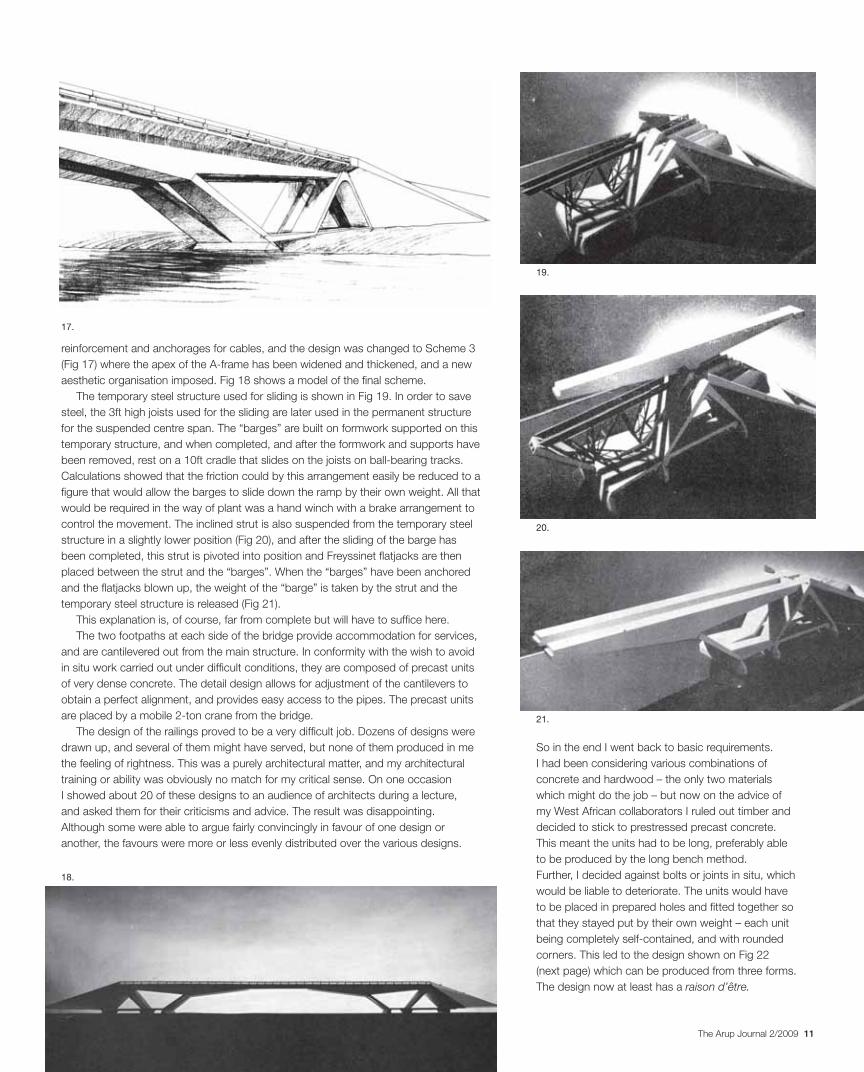
reinforcement and anchorages for cables, and the design was changed to Scheme 3
(Fig 17) where the apex of the A-frame has been widened and thickened, and a new
aesthetic organisation imposed. Fig 18 shows a model of the final scheme.
The temporary steel structure used for sliding is shown in Fig 19. In order to save
steel, the 3ft high joists used for the sliding are later used in the permanent structure
for the suspended centre span. The “barges” are built on formwork supported on this
temporary structure, and when completed, and after the formwork and supports have
been removed, rest on a 10ft cradle that slides on the joists on ball-bearing tracks.
Calculations showed that the friction could by this arrangement easily be reduced to a
figure that would allow the barges to slide down the ramp by their own weight. All that
would be required in the way of plant was a hand winch with a brake arrangement to
control the movement. The inclined strut is also suspended from the temporary steel
structure in a slightly lower position (Fig 20), and after the sliding of the barge has
been completed, this strut is pivoted into position and Freyssinet flatjacks are then
placed between the strut and the “barges”. When the “barges” have been anchored
and the flatjacks blown up, the weight of the “barge” is taken by the strut and the
temporary steel structure is released (Fig 21).
This explanation is, of course, far from complete but will have to suffice here.
The two footpaths at each side of the bridge provide accommodation for services,
and are cantilevered out from the main structure. In conformity with the wish to avoid
in situ work carried out under difficult conditions, they are composed of precast units
of very dense concrete. The detail design allows for adjustment of the cantilevers to
obtain a perfect alignment, and provides easy access to the pipes. The precast units
are placed by a mobile 2-ton crane from the bridge.
The design of the railings proved to be a very difficult job. Dozens of designs were
drawn up, and several of them might have served, but none of them produced in me
the feeling of rightness. This was a purely architectural matter, and my architectural
training or ability was obviously no match for my critical sense. On one occasion
I showed about 20 of these designs to an audience of architects during a lecture,
and asked them for their criticisms and advice. The result was disappointing.
Although some were able to argue fairly convincingly in favour of one design or
another, the favours were more or less evenly distributed over the various designs.
17.
18.
19.
20.
21.

12 The Arup Journal 2/2009
Again, it is desirable to have as few obstructions
as possible between the outer embankments,
because the river can rise right to the top of these
embankments and the current may be very swift.
For the same reason it would obviously be cheaper
to avoid staging in the river.
The design should be clear from Fig 23.
In cross-section the bridge consists of two 12ft high
hollow prestressed concrete girders, with steel joists
stuck through holes in the girders at 2ft centres to
support the roadway and the cantilevered footways.
These are timber decking with a covering of asphalt.
There are only four main piers, two on each side,
the span between the centre piers, where practically
all the loads are concentrated, being 581ft. On these
piers A-frames of hollow steel construction support
two main cables which run from the outer piers or
counterweights at the back over the A-frame and
then to the outer end of each concrete girder. These
cables in turn support a second set of cables as
indicated. Between these two cantilever systems a
centre span of aluminium construction is suspended.
The girders are, to begin with, interrupted at the
main pier and at the point where the secondary
cables support the girders. This makes the system
statically determined for the dead load and when
the cables have been stressed – by jacks under
the main counterweights – and the length of cable
adjusted to ensure that the different portions of
concrete girders form a straight line. Then the joists
The Black Volta Bridge, Ghana
The next scheme, so far only a sketch design, is also for a bridge in Ghana, but in
the northern part of the country where the atmosphere is dry, and where steel and
aluminium are possible materials to use. The bridge is to span the Black Volta, which
is approximately 505ft wide at this point, but runs in a valley 984ft wide, which is
flooded for three months of the year. The profile is as indicated in Fig 23, with a 36ft
drop from the outer embankments to the flat valley and further 25ft embankments
down to the river, when it is not in flood.
22.
23.
13The Arup Journal 2/2009
properties are most suited. The guiding principle
has been economy of construction, and this has
certainly been achieved in this case, if one adheres
to the decision that it is undesirable to have supports
in the river.
The principle of constructing the two halves of
the bridge on the banks of the river and then turning
them out would in this case cut the cost of the
bridge considerably as it would make construction
independent of the yearly floods. If the four piers
were built in one season, and the steel A-frames,
formwork and cables were brought to the site, then
in the next nine months’ season the prestressed
concrete girders and the supporting cables could be
constructed, and probably the decks finished as well,
because this is only a matter of sticking the joists
through the holes in the concrete girders and laying
the hardwood roadway.
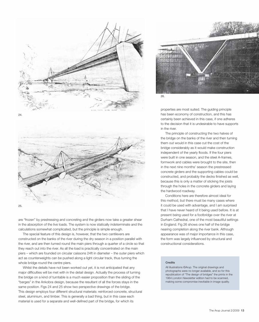
Conditions here are therefore almost ideal for
this method, but there must be many cases where
it could be used with advantage, and I am surprised
that I have never heard of it being used before. It is at
present being used for a footbridge over the river at
Durham Cathedral, one of the most beautiful settings
in England. Fig 26 shows one half of the bridge
nearing completion along the river bank. Although
appearance was of major importance in this case,
the form was largely influenced by structural and
constructional considerations.
Credits
All illustrations ©Arup. The original drawings and
photographs were no longer available, and so for this
republication of “The design of bridges” the prints in the
1964 London Newsletter edition had to be scanned,
making some compromise inevitable in image quality.
are “frozen” by prestressing and concreting and the girders now take a greater shear
in the absorption of the live loads. The system is now statically indeterminate and the
calculations somewhat complicated, but the principle is simple enough.
The special feature of this design is, however, that the two cantilevers are
constructed on the banks of the river during the dry season in a position parallel with
the river, and are then turned round the main piers through a quarter of a circle so that
they reach out into the river. As all the load is practically concentrated on the main
piers – which are founded on circular caissons 24ft in diameter – the outer piers which
act as counterweights can be pushed along a light circular track, thus turning the
whole bridge round the centre piers.
Whilst the details have not been worked out yet, it is not anticipated that any
major difficulties will be met with in the detail design. Actually the process of turning
the bridge on a kind of turntable is a much easier proposition than the sliding of the
“barges” in the Ankobra design, because the resultant of all the forces stays in the
same position. Figs 24 and 25 show two perspective drawings of the bridge.
This design employs four different structural materials: reinforced concrete, structural
steel, aluminium, and timber. This is generally a bad thing, but in this case each
material is used for a separate and well-defined part of the bridge, for which its
24.
25.
26.
14 The Arup Journal 2/2009
Dealing with diversity
The theme of this design school is “diversity”. As a musician I naturally relate it to
a musical form, and the musical form I am going to apply is that of the rhapsody.
Over the next three-quarters of an hour or so, I am going to rhapsodise in favour
of diversity as a balance to the human tendency to rationalise, to simplify, and to
collectivise individuality. I will also illustrate my argument with a diversity of
different sounds.
Where do we start with diversity? Back at the beginning. It was during an
especially harsh glacial period around 130 000 years ago (perhaps as far back as
195 000 years1) that homo sapiens evolved in Africa, the earliest specimens so far
being found at Omo Kibish in Ethiopia. Our species behaved in quite a different way
from its predecessors: the archaeological record begins to show traces of art, ritual,
and a new range of technologies, reflecting a more creative mind. A creative mind
solves problems, a creative mind embraces a choice of solutions to problems, a
creative mind does not think that there is one solution to all problems – and hence
diversity has probably been wired into our brains for at least 130 000 years.
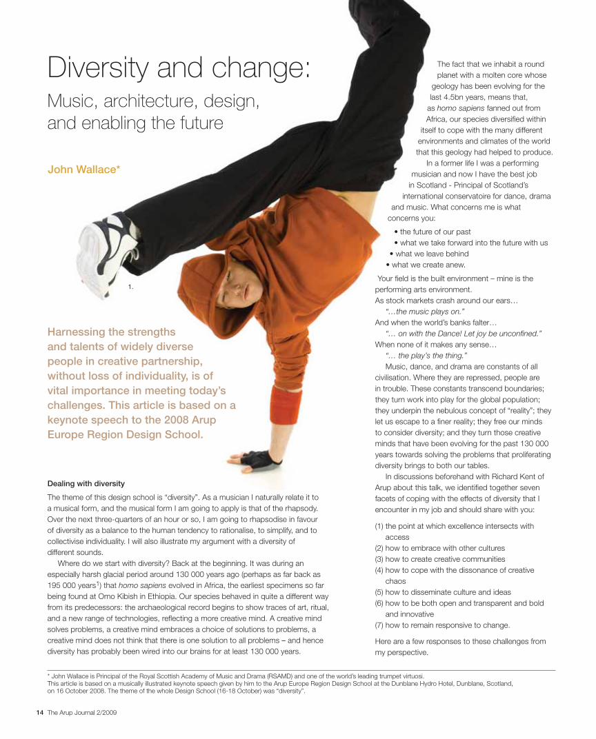
Diversity and change: Music, architecture, design, and enabling the future
The fact that we inhabit a round
planet with a molten core whose
geology has been evolving for the
last 4.5bn years, means that,
as homo sapiens fanned out from
Africa, our species diversified within
itself to cope with the many different
environments and climates of the world
that this geology had helped to produce.
In a former life I was a performing
musician and now I have the best job
in Scotland - Principal of Scotland’s
international conservatoire for dance, drama
and music. What concerns me is what
concerns you:
Your field is the built environment – mine is the
performing arts environment.
As stock markets crash around our ears…
“…the music plays on.”And when the world’s banks falter…
“… on with the Dance! Let joy be unconfined.”When none of it makes any sense…
“… the play’s the thing.”Music, dance, and drama are constants of all
civilisation. Where they are repressed, people are
in trouble. These constants transcend boundaries;
they turn work into play for the global population;
they underpin the nebulous concept of “reality”; they
let us escape to a finer reality; they free our minds
to consider diversity; and they turn those creative
minds that have been evolving for the past 130 000
years towards solving the problems that proliferating
diversity brings to both our tables.
In discussions beforehand with Richard Kent of
Arup about this talk, we identified together seven
facets of coping with the effects of diversity that I
encounter in my job and should share with you:
(1) the point at which excellence intersects with
access
(2) how to embrace with other cultures
(3) how to create creative communities
(4) how to cope with the dissonance of creative
chaos
(5) how to disseminate culture and ideas
(6) how to be both open and transparent and bold
and innovative
(7) how to remain responsive to change.
Here are a few responses to these challenges from
my perspective.
John Wallace*
1.
* John Wallace is Principal of the Royal Scottish Academy of Music and Drama (RSAMD) and one of the world’s leading trumpet virtuosi. This article is based on a musically illustrated keynote speech given by him to the Arup Europe Region Design School at the Dunblane Hydro Hotel, Dunblane, Scotland, on 16 October 2008. The theme of the whole Design School (16-18 October) was “diversity”.
Harnessing the strengths and talents of widely diverse people in creative partnership, without loss of individuality, is of vital importance in meeting today’s challenges. This article is based on a keynote speech to the 2008 Arup Europe Region Design School.
15The Arup Journal 2/2009
year in a performing arts institution should be a free-
form creative beginnings programme.
(4) how to cope with the dissonance of creativechaos (and police the consequent mess)
Always have enough productive work with clear and
realistic deadlines for your resident geniuses on your
core business (our core business being our students).
With this in mind we go out actively recruiting first-
rate demanding students nationally and internationally
to create a centre of excellence with extremely high
international standards in Scotland, for Scotland.
(5) how to disseminate culture and ideas (whensurrounded by intellectual apathy and itsbedfellows, hubris and greed)
Get them young, temper human hubris with humility,
create the context to inspire the cultural movers
and shakers of the future to perform well in all the
timeless topics humans have had to deal with over
the last 130 000 years, and will have to through the
stock market crashes of the next 130 000 years, and
create respect amongst those young people for the
essential human values of freedom and equality.
(1) the point at which excellence intersects with access
Diversity makes it more difficult to identify what is good; true excellence and the
sacrifices that it entails exclude most of the population; a professional cadre needs a
participative population to support its profession; excellence needs access, and vice
versa. We at the RSAMD are feeling our way to a balance of excellence with access
through our 16 Youthworks centres from Dumfries in the south of Scotland to Orkney
in the north, dealing with 1600 students per week. And we are dealing with the
challenges raised by the differently abled through the delivery of equal opportunities
training to staff and projects within the curriculum to students by the Birds of Paradise
Theatre Company, Scotland’s “first inclusive touring theatre company working with
casts of disabled and non-disabled professional actors”7.
(2) how to embrace with other cultures
We are dealing with this through the delivery of world music modules by the Scottish
Academy of Asian Arts on our Scottish Traditional Music courses, and through
assertive recruitment among the ethnic minorities.
3) how to create creative communities…
… out of moody individuals – and most importantly, how to promote a café culture
in a cold climate (in one of the top 10 Lonely Planet cities in the world)? This led
to the formation of democratic creative teams amongst my colleagues out of a
former hierarchical structure. (I think you call it empowerment.) I’m still working on
the dynamics of the creative relationships and the solo and ensemble behaviours
of artistic administrators. The dissolution of the works canteen and replacement
by a “creative space” has helped, as has the provision of a decent cup of coffee!
Encourage students to self-generate, to think for themselves, to put on their own gigs,
to adopt the Danish idea of Fundament – that the first eight weeks of any academic
Design in music
Music grows out of its environment,
like architecture and design and
engineering. Sometimes music grows
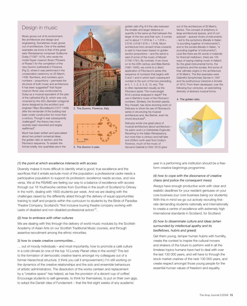
out of architecture. One of the earliest
examples we know is that of the great
early Renaissance composer Guillaume
Dufay (?1397-1474), who wrote his
motet Nuper rosarum flores (“Flowers
of Roses”) for the completion of the
new Duomo (cathedral) in Florence
(Fig 2), where it was performed in the
consecration ceremony on 25 March,
1436. Numbers, and numbers upon
numbers – proportions – permeate the
structure of both music and architecture.
It has been suggested2 that Nuperrosarum flores was constructed by
Dufay as a musical equivalent of the plan
of the cathedral (Fig 3), which was only
crowned by the 42m diameter octagonal
dome designed by the architect and
engineer Fillipo Brunelleschi (1377-1446)
after the remainder of the building had
been under construction for more than
a century. Though it was subsequently
challenged3, the theory has more
recently been reworked and largely
reaffirmed4.
Much has been written and speculated
about two potent numerical ideas,
the golden ratio or section, and the
Fibonacci sequence. To explain the
former briefly, two quantities are in the
golden ratio (Fig 4) if the ratio between
the smaller and larger distance or
quantity is the same as that between the
larger of the two and their sum. It comes
out to about 1:1.618 (ie 1 + 1.618 =
2.618; 2.618/1.618 = 1.618). Much
architecture from ancient times onwards
is said to have been based on golden
section proportions – and the same is
said of some of the music of Mozart
(1756-1791). By contrast, if we move
on to the 20th century and Béla Bartók
(1881-1945), we come to a direct
application of Fibonacci’s series (the
sequence of numbers that begins with
0 and 1 and in which each subsequent
number is the sum of the two preceding,
ie 0, 1, 1, 2, 3, 5, 8, 13, etc). This
is often represented visually as the
Fibonacci spiral. The musicologist
Ernö Lendvai analysed in depth5 the
use in Bartók’s music of the Fibonacci
numbers. Similarly, the Scottish pianist,
Roy Howatt, has done stunning work on
Debussy to show his use of Fibonacci’s
series in structuring his musical
architecture and, like Bartok, even his
chord structures6.
Debussy wrote one great piece of
musical architecture about architecture –
his piano work La Cathédrale Engloutie.
Reverting to the Italian Renaissance,
but more than a century and half later
and 200km north-east from Dufay’s
Florence, much of the music of
Giovanni Gabrieli (c1555-1612) grew
out of the architecture of St Mark’s,
Venice. The concept of antiphony in
large architectural spaces, and of corispezzati – spaced choirs of instruments
– led to the symphony (literally in Italian
“a sounding together of instruments”),
and to the sonata (literally in Italian, “a
sounding together of instruments”).
(Just like there are 65 words in Icelandic
for financial meltdown, there are 125
ways of saying making music in Italian!)
So the great instrumental forms, the
symphony and the sonata, find some of
their ultimate origins in the architecture
of St Mark’s. The first examples were
Gabrieli’s Symphoniae Sacrae in 1597
and his posthumous Canzone e Sonateof 1615. From them developed, over the
following four centuries, an astonishing
diversity of abstract musical forms.
4. The golden ratio.
2. The Duomo, Florence, Italy.
3. The Duomo in plan.
0 30m
16 The Arup Journal 2/2009
whose numbers are growing and whose imperatives are morphing. The Academy is
now a bionic building with refreshed body parts. Ideally, we need a building the interior
of which we can constantly reconfigure to reflect our changing needs.
We will require buildings that have an infinitely greater capacity than at present for
flexibility, adaptability, and future-proofing. Our productions in future, all the way to
costume and set design and construction, need to embrace the latest filmic, flying,
and virtual technologies. Our business is professionals in training now for the future of
performance and production.
And human beings now consume a greater diversity of performance product per
capita than at any other time in history.
And that diversity is set to grow, because of society and because of the diversity of
organisations within that society.
We now think of ourselves as a sedentary society, the members of which live in
fixed abodes, but another thing that arose in my conversations with Richard was
how much that “sedentary” population actually travels, and just what itchy feet it
has. Richard prised out of me the contention that the most successful amongst the
present population, including the most successful businesspeople, have returned to
a modern form of nomadry. “Nomadry” and “itchy feet” are underlying components
of our society; they surfaced rapidly during the course of the 20th century and now
continue into the 21st century.
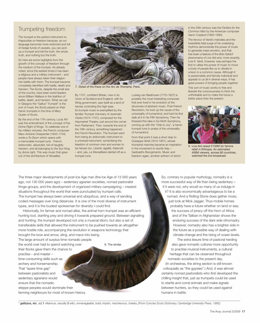
The growth and spread of large urban centres has created a massive class of
nomads, called commuters. Similarly, the mass exodus to Spanish beaches every
summer has created another class of nomads called tourists, as has the repopulation
of the French countryside by the English and Dutch and their maisons secondaires.
There is thus an annual migration pattern, most visible in the crammed motorways,
railways, and airports every Bank Holiday. Add to that the growth of the mobile phone,
by which entire populations can be in two places at once while walking, driving, and
soon flying. And, we want to consume our culture on the move, as part of granular
dispersed constituencies of same and similar interests. The inner nomad in each and
every one of us is a restless creature whose instincts it is very hard to pacify.
Nomadry and the trumpet
My specialism is music. And I think I understand nomadry. I used to tour for between
six and nine months of the year.
And my instrument is the trumpet. Two early examples are the “cow horn” trumpet
and the didge or didjeridoo. The most well-known of the former is the Jewish shofar,
still played in synagogues to this day; if the walls of Jericho ever really were blown
down, it would have been instruments like these that were responsible.
“Didjeridoo” is a descriptive onomatopoeic word dating back only to 1798, but
it covers an astonishing variety of wooden trumpets in all shapes and sizes, with
hundreds of diverse aboriginal tribal names, and a history of usage that goes back
at least 1500 years.
(6) how to be open and transparent, and bold and innovative, at the same time
I haven’t succeeded in this yet, but I think the secret
is to prepare a measured tempo of communication
and to have great powers of acceleration and
deceleration, all the while taking your people with
you. I am Action Man – but actions create reactions
and being one step ahead of those reactions means
keeping some things to yourself, which isn’t really
open and transparent. So this is a difficult one for any
leader of anything in a modern democracy.
(7) how to remain responsive to change (and a caveat here - when much of it is so superficial)
Surround yourself with people who have superior
powers of analysis to your own, and be prepared to
change your mind – unless your instinct, formed by
130 000 years of genetic coding, begins to scream
at you. Remind yourself of your own personal value
system, which should be somewhere up there
with that of St Francis of Assisi. When in doubt,
do nothing, a difficult concept for Action Man (or
Woman), but… doing nothing is a marvellous
prelude to action.
Diversity, space, and nomadry
In addition to these magnificent seven facets of
dealing with diversity, I also discussed with Richard
some of the space challenges I face and for which
my training left me totally unprepared. I am the
worst thing an architect or designer or engineer
can encounter: a performer with no practical nous
whatsoever – beyond lip, hand, brain and lung
co-ordination – but with limitless needs and
panoramic enthusiasms.
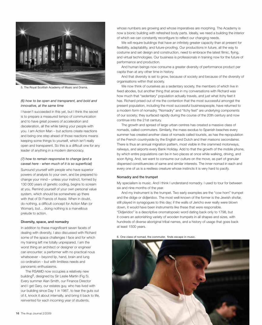
The RSAMD now occupies a relatively new
building8, designed by Sir Leslie Martin (Fig 5).
Every summer Alan Smith, our Finance Director
and I get Gary, our estates guy, who has lived with
our building since Day 1 in 1987, to tear the guts out
of it, knock it about internally, and bring it back to life,
reinvented for each incoming year of students,
6. One class of nomad, the commuter, finds escape in music.
5. The Royal Scottish Academy of Music and Drama.
17The Arup Journal 2/2009
So, contrary to popular mythology, nomadry is a
more successful way of life than being sedentary –
if it were not, why would so many of us indulge in
it? It is also economically advantageous to be a
nomad. And a Rolling Stone does gather moss;
just look at Mick Jagger. Thus mobile homes
probably have a future whether on land or sea;
the success of piracy off the Horn of Africa
and of the Taliban in Afghanistan shows the
enduring success of the dark side ofnomadry.
However, nomadry also has a brighter side in
the future as a possible way of dealing with
climate change and the rising of ocean levels.
The extra leisure time of pastoral herding
also gave nomadic cultures more opportunity
to practise musical instruments, a cultural
heritage that can be observed throughout
nomadic societies to the present day.
(In orchestras, the string section is still known
colloquially as “the gypsies”.) And, it was almost
certainly nomad pastoralists who first developed the
chilling insight that, just as trumpets could be used
to startle and corral animals and make signals
between hunters, so they could be used against
humans in battle.
The three major developments of post-Ice Age man (the Ice Age of 13 000 years
ago, not 130 000 years ago) – sedentary agrarian societies, nomad pastoralist
fringe-groups, and the development of organized military campaigning – created
situations throughout the world that were punctuated by trumpet calls.
The trumpet has always been universal and ubiquitous, and a way of sending
coded messages over long distances. It is one of the most diverse of instrument
types, and it is the loudest spokesman for diversity I could find.
Historically, for farmer and nomad alike, the animal horn trumpet was an efficient
hunting tool, startling prey and driving it towards prepared ground. Between signalling
and hunting, the trumpet developed not only a musical idiom, but also a set of
transferable skills that allowed the instrument to be pushed towards an altogether
more hostile role, accompanying the revolution in weapons technology that
brought the bow and arrow, sling, and mace into being.
The large amount of surplus time nomadic people
the world over had to spend watching over
their flocks gave them the chance to
practise – and master –
time-consuming skills such as
archery and horsemanship.
That “spare time gap”
between pastoralists and
sedentary agrarians would
ensure that the nomadic
steppe peoples would dominate their
farming neighbours for most of known history.
Trumpeting freedomThe trumpet is the perfect instrument to
rhapsodise on freedom because, as our
language becomes more restricted and full
of hedge funds of caveats, you can pick
up a trumpet and tell the truth, the whole
truth, and nothing but the truth.
So here are some highlights from the
growth of the concept of freedom through
the medium of the trumpet. As already
noted, since the earliest times it has been
a religious and a military instrument – and
people have always taken their religion
into battle with them. The trumpet became
completely identified with battle, death and
heroism. The Scots, despite the small size
of the country, have been world leaders
since William Wallace in the triathlon of
battle, death, and heroism. What we call
in Glasgow the “Gallus* Trumpet” is the
sort of music the Scots played on their
heroic trumpets in the time of Mary
Queen of Scots.
By the end of the 17th century, Louis XIV
was the embodiment of the concept of the
Divine Right of Kings. To celebrate one of
his military victories, the French composer
Marc-Antoine Charpentier (1643-1704)
wrote a Te Deum which opens with
a memorable trumpet tune - French,
aristocratic, absolutist, full of haughty
heroism, and all belonging to the Sun King
by divine right. This was music that grew
out of the architecture of Versailles.
By 1707, confident Britain, new in its
Union of Scotland and England, with its
Whig government, saw itself as a land of
heroes controlling the high seas.
Its trumpet music is exemplified by the
familiar Trumpet Voluntary of Jeremiah
Clarke (1674-1707), composed for the
Haymarket Theatre, just around the corner
from Parliament. Then, towards the end of
the 18th century, something happened -
the French Revolution. The trumpet went
from being an aristocratic instrument to
a universal instrument, symbolising the
freedom of common men and women to
be heroes too. Liberté, égalité, fraternité– and, yes, La Marseillaise started off as a
trumpet tune.
Ludwig van Beethoven (1770-1827) is
possibly the most interesting composer
that ever lived in his evolution of the
structures of abstract music. Post-French
Revolution, he took up the cause of the
universality of humankind, and had his first
stab at it in his Fifth Symphony. Then he
finessed this idea in his Ninth Symphony,
coming up with the “Ode to Joy”, a heroic
trumpet tune in praise of the universality
of humankind.
From that point it was a short step to
Guiseppe Verdi (1813-1901), whose
triumphal marches became an inspiration
in the movement to reunify Italy –
Garibaldi’s Risorgimento. Music and
freedom again, another anthem of which
in the 20th century was the Fanfare for the Common Man by the American composer
Aaron Copland (1900-1990).
The fervour of Verdi’s melodies and the
irresistible tidal surge of his underlying
rhythms demonstrate the power of music
to generate mass emotion, and that
has been a feature of the Bob Geldof
phenomena of Live Aid and, more recently,
Live 8. Verdi, however, was perhaps the
first to utilise the power of music to move
a body of people like us to vibrate in
unison in a common cause. Although it
is passionately and fiercely individual and
appeals to us all in diverse ways, it has
great powers of bringing people together.
This sort of music works to free and
liberate the consciousness to think the
unthinkable and to make the future a
better place than the present.
* gall(o)us, etc. adj 1 villainous, rascally 2 wild, unmanageable, bold; impish, mischievous, cheeky. [From Concise Scots Dictionary, Cambridge University Press, 1985].
9. The shofar.
7. Detail of the frieze on the Arc de Triomphe, Paris.
8. Live Aid raised £150M for famine relief in Ethiopia. An estimated 400M viewers, across 60 countries, watched the live broadcast.
18 The Arup Journal 2/2009
What about the engineering of these ancient trumpets?
Early man fashioned them from any suitable local elements. Human ingenuity can
achieve musical miracles with materials like wood and bark, bamboo, gourds,
crustacean shells, and mammal horns. The horns of wild or domesticated animals
can be crafted into simple trumpets by hollowing out the core with a heated stick.
Conch shells can be dried and bored with a blow-hole. Tree-branches can be
hollowed out with fire or termites. Bark can be stretched around a wooden skeleton to
form a cone-like trumpet or a massive horn. Even human remains have been hollowed
out and lip-blown.
So formerly, before mass production, mass marketing, and global distribution,
there was astonishing diversity in something as simple as a tube that you blew
through. And, in addition, the many ways a lip-blown instrument can be primitively
manufactured means that the trumpet often predates the earliest collective memories
of a society: developing into a marker of identity and of cultural pride.
Study of even the earliest references to trumpets reveals the instrument to hold
an aura of antiquity, a tool bequeathed to man from an ancient, unrecorded source.
The Greeks, for instance, never formed a creation myth for their trumpet – the salpinx
- as they had for their plucked string instrument, the lyre, and the woodwind aulos.
Other instruments required an explanation for their coming into being: the trumpet
had simply “always existed”. It is an example of an early man-made object that acts
universally as a cultural transmitter, communicating more than a simple message
between living people.
Very similar to some of our greatest buildings.
Taking the past into the future
But, when we are thinking of the future of our past,
and of what we are going to take with us into the
future from that past, it is remarkable to dwell on the
fact that human beings, from the moment of their
emergence as a cultural as well as a biological entity,
have in one way or other collected, preserved, and
hoarded items that have no other significance than as
carriers of messages from the past.
In October 2008 we finally realised that we had
entered the 21st century. The present time may prove
to be a watershed and nothing may ever be quite the
same again. Just as, in music at any rate, the 20th
century began on Thursday, 29 May 1913 with the
shock of Stravinsky’s Le Sacre du Printemps –
a landmark, an aural mark, of modernity.
What are you going to do next, after this
watershed? How are you going to create and
recreate our physical environment? How are you
going to do your bit for the billions of people out
there?
I do not know your field as well as you do, but I do
think there are parallels between architecture and the
performance arts. Perhaps it may be helpful to share
with you my route forward.
I have here in my brain, body, and trumpet a
whole condensation of 130 000 years of human
evolution, just as you have in your fields. I know I
am just stating the obvious, but between my body
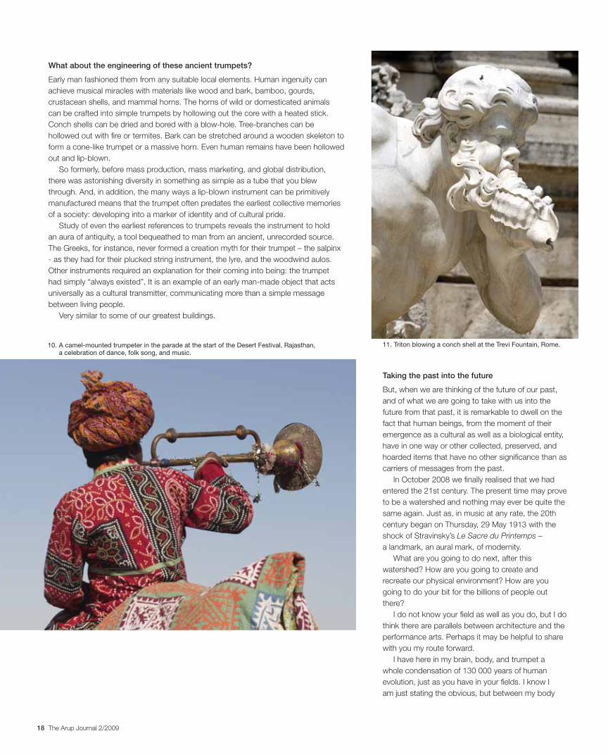
11. Triton blowing a conch shell at the Trevi Fountain, Rome.10. A camel-mounted trumpeter in the parade at the start of the Desert Festival, Rajasthan, a celebration of dance, folk song, and music.

19The Arup Journal 2/2009
and this artefact, this trumpet, which has grown out of our environment through the
millennia, there is enough genetic knowledge, experienced through basic instincts, to
deal with anything that comes my way, and I can express this knowledge with the aid
of this artefact when words are not enough.
My route lies definitely in keeping the gene pool of diversity of choice open, and
in countering the pervasive spread of deadening orthodoxy that we meet every day,
because of cost pressures, with a profusion of eccentric solutions.
And the fuel of my route is the power of dance, drama, and music to free young
minds: the ability of the performing arts to be a powerful educational tool and to
expand a society’s consciousness and raise a nation’s game. And wherever the
performing arts perform and flourish, and human beings have the confidence and the
self-esteem to perform, modern economies perform and flourish. I believe that the
value of performance to the world has to be enormous.
In music, it is firstly the sheer sound that has the effect, initially on the individual
and then, like a virus, on the masses. Then it’s the melody, harmony, rhythm,
phrasing, feeling; all the complex mix of emotions from passionate to dispassionate,
that works its magic. And playing an instrument itself – for the player it is like getting
the keys to the doors of Paradise.
Conclusion
I said at the outset that I was going to rhapsodise in favour of diversity as a balance
to the human tendency to rationalise, to simplify, and to collectivise individuality.
The concept of individuality – treating everyone as an individual – requires freedom,
and therefore freedom is a prerequisite for diversity. But it seems difficult to blow
the trumpet of freedom when all about us there is an increased imperative for the
straitjacket of rules and regulation in the financial sector. However, human ingenuity
will out, and the freedom of the human spirit will prevail.
And what sort of creative organisation moves a body of diverse people to vibrate
in unison whilst preserving the freedom of their own individuality? A partnership like
Arup. Looking into the future, this partnership structure is the key to keeping your
gene pool of diversity high. People like me, on the outside, admire your form of
organisation, and when we look at our own organisations, we realise how much better
diversity would flourish within our organisations with your sort of structure.
So to finish, in the most competitive market any of us may have experienced,
we have to encourage diversity. On the edge. Exciting. Forbidden. Original. New.
Irreverent. In your face. Brooking challenge and seeing it off – diversity.
Credits
Illustrations: © Dreamstime - 1 Redbaron, 2 Gijs Van
Ouwerkerk, 4 Putnik, 7 Rubens Alarcon, 8 David Snyder,
9 Noam Armonn, 10 Jeremy Richards, 11 David Bailey,
13 Xavier Marchant; 3 Nigel Whale; 5 KK Dundas;
© iStockphoto - 6 David Vadala, 12 Arbon Alija.
References
(1) http://tinyurl.com/yqdbbl
(2) WARREN, C. Brunelleschi’s Dome and Dufay’s Motet.
The Musical Quarterly, 59, pp92-105, 1973.
(3) WRIGHT, C. Dufay’s Nuper rosarum flores, King Solomon’s
Temple, and the Veneration of the Virgin. Journal of the American Musicological Society, 47, pp395-441, 1994.
(4) TRACHTENBERG, M. Architecture and music reunited: A new
reading of Dufay’s Nuper Rosarum Flares and the Cathedral of
Florence. Renaissance Quarterly, 22 September 2001.
(5) LENDVAI, E. Béla Bartók: An analysis of his music. Kahn &
Averill, 1971.
(6) HOWAT, R. Debussy in proportion: A musical analysis.
Cambridge University Press, 1983.
(7) http:// www.birdsofparadisetheatre.co.uk
(8) http:// www.rsamd.ac.uk/foi/categories/Physical_Resources.
html
After joining the London Symphony Orchestra and
then moving to the Philharmonia Orchestra as Principal
Trumpet, John Wallace enjoyed an international career
as a trumpet virtuoso. In 1986 he founded The Wallace
Collection, a brass ensemble specialising in modern
repertoire challenging to performers and listeners alike.
Amongst their many recordings is a disc entitled “The
Golden Section” – music of John Tavener, Jim Parker,
William Matthias, Michael Nyman, and James MacMillan.
John Wallace became Principal of the The Royal Scottish
Academy of Music and Drama in 2002 (after which the
remaining members of The Wallace Collection renamed
their group The Golden Section).
12. Trumpets often feature in modern band line-ups.
13. The didjeridoo in a very modern “call to action”.

20 The Arup Journal 2/2009
In December 2000 public inquiries were held to consider the environmental statement
and designation orders for the M1/Westlink upgrade. Following proposed changes
to the design, a further inquiry was held in December 2002, and the vesting orders,
which provide the necessary land, became operative in September 2004.
The procurement process ran throughout 2004 and 2005, resulting in final award and
start of construction in early 2006.
Purpose
The project forms part of Belfast’s current £2bn worth of investment, signalling that
the city is getting back on its feet after more than 30 years of difficult times. It was
recognised that the road network was of key importance to the Northern Ireland
economy’s success. This scheme improves the links between the M1, M2, and M3
motorways, enables better access to the south and west of the province and to
the Republic of Ireland, and facilitates connections to Belfast city centre, the Port of
Belfast, and Belfast City Airport.
Westlink /M1, Northern Ireland
The M1/Westlink upgrade is Northern Ireland’s top priority road improvement scheme. It was completed and opened six months ahead of programme. Part of the Trans-European Road Network, this major project is vital for shorter and more reliable journeys in and around Belfast. Arup carried out the detailed design for the design/build contractor.
Dom Ainger John Border Chris Caves Paola Dalla Valle Chris Furneaux Tim Gammons John Griffiths Deepak Jayaram Ray Kendal Ronnie Palmer Alan Phear Andy Ross Guy Stabler
History
Introduction
Constructed on the west side of Belfast, the original
Westlink was completed in March 1983 to connect
Northern Ireland’s M1, M2, and M3 motorways with
3.38km of dual carriageway. By 1998, daily traffic
levels had grown from the design 35 000 vehicles
to 65 000, putting pressure on key junctions at
Grosvenor Road and Broadway. Delays at peak times
were creating disruption and frustration for travellers,
bringing the link close to breaking point, and it was
recognised that the bottlenecks on this key strategic
route needed to be addressed. A scheme was
developed with the following objectives:
demand between M1/M2/M3 and Belfast Port.
sustainable transport means.
the latest ITS techniques.
environment.
1. Stockman’s Lane Junction.

21The Arup Journal 2/2009
Scheme 4Scheme 2
Scheme 3
Sandyknowes junction
Greencastle junction
Junction 7
Safety fencesystem
L O U G H N E A G H
A N T R I M
B E L F A S T
L I S B U R N
L U R G A N
Divis Street junction
Scheme 1
Stockman’s Lane junctionBelfast
Dublin
Londonderry/Derry
Galway
Enniskillen
Omagh
N E W T O W N A B B E Y
0 5km
0 50km
PromoterDepartment of
Regional DevelopmentRoads Service
DBFO companyHighway Management
(City) Ltd
D+B contractorHighway Management
Construction
D+B designerArup
Arup team
Graham
Farrans
Bilfinger Berger
Joint veture partners
Complexity
The upgrade is one of the most challenging projects
ever undertaken by the Department for Regional
Development Roads Service. The road runs through
a very constrained corridor with homes, businesses,
and a hospital hugging both sides. As a result of
pressure at public inquiry, much of the route was to
be below ground level. This presented challenges, as
the road runs through some very soft areas of ground
with high groundwater, known locally as “sleech”, laid
down since the last Ice Age.
The Blackstaff river runs the length of the route
and other tributaries cross it. Interwoven at the
junctions is a tangle of underground and overground
utility services ranging from large-diameter gravity
and pumped sewers, gas pipelines, and high-voltage
overhead power transmission lines. In addition the
live road and motorway network runs through the site
and needed to be kept moving.
The contractual arrangement
The first roads DBFO of its type in Northern Ireland
The M1/Westlink upgrade has been delivered as part
of a public/private partnership. The private sector
raised the finance for the improvement schemes,
and will be repaid through service payments for
maintaining the road network and ensuring its
availability throughout the 30-year life of the contract.
This DBFO form of contract is based on that used
successfully in the UK by the Highways Agency
and, as far as Arup is concerned, builds on the
firm’s previous experience as designer in this form of
contract, notably of the M6 Toll1, completed in 2003.
The Department for Regional Development
(DRD) awarded the DBFO contract to Highway
Management (City) Ltd (HMG). Roads Service
managed the contract for DRD. HMG, the “DBFO
company”, appointed Highway Management
Construction (HMC) as the main contractor under the
design/build contract, and in turn HMC appointed
Arup as designer (Fig 3). HMC is a consortium of
local contractors John Graham (Dromore), and
Project outline
The construction element of the entire DBFO (design/build/finance/operate) project
comprises four schemes packaged together (Fig 2). The upgrade (Scheme 1) involves
major improvements to the M1 and Westlink between the Stockman’s Lane junction
and the Divis Street junction. These include:
the M1 over Stockman’s Lane Junction, along with widening and signalisation of
the roundabout and improvements to the slip roads
by means of underpass structures
The DBFO project also involves:
Hospital, junction 7 of the M2
Greencastle junctions
to include state-of-the-art lane control variable message signing, CCTV,
emergency telephones, incident detection and transmission networking to
the motorway control centre, as well as replacement of safety fence systems
to current standards.
2. Key map.
3. The contracting parties and their roles.

22 The Arup Journal 2/2009
Project management
Arup was appointed under a fixed fee contract for the detailed design, and so careful
management of scope and fee were required. The tender fee had been built up
from detailed estimates of the budgets required by individual disciplines to deliver
the design. To help comprehend the full scope, and reduce the risk of missing or
underestimating design elements needed, the team prepared a design information
schedule during the tender.
To manage the budget and monitor spending under all the elements, the tender
fee was broken down under more than 150 headings, each of which was assigned
its own share of the fee. If and when required and justified, the project manager drew
down additional fee from the risk contingency and added it to the individual task
budgets. In this way, spend against the original estimates was carefully tracked, and
any projected overspend identified early.
The design information release schedule, prepared during tender, was bound into
the contact. This identified all deliverable packages and dates by which they would be
produced. This document evolved over the project’s lifetime and by agreement with
the contractor; as and when scheme priorities changed, amendments were made to
the delivery programme to suit construction progress.
All contract drawings and documents were submitted electronically on the project
extranet, Aconex. Every main participant had access to this, including Roads Service
and its agents, HMG (the DBFO company), HMC (contractor), and Arup and all its
subconsultants. Workflow procedures were established to allow documents to be
submitted for internal review, for Roads Service review, and for construction, all on
this system. Aconex allows for common access to documents and clear auditable
history of review comments and responses.
Northstone (NI) Ltd (formerly Farrans Ltd), and the
major German group Bilfinger Berger. Separately,
HMG appointed Highway Management Maintenance
(HMM) for the routine maintenance of the DBFO
highway network.
Arup’s scope of work included design of highways
and structures, drainage, geotechnics and traffic
signalling, as well as environmental mitigation,
motorway communications, and site support.
The DBFO procurement process started in
January 2004, with the issue of the works contract
notice to the Official Journal of the European Union.
A prequalification submission was prepared, with
Arup supporting the HMC joint venture; tender
documentation was issued in April 2004 to HMC and
three other groups, and an intense tender period
ensued, with Arup completing preliminary design and
risk assessments to allow the tender submission to
be made on 15 September 2004.
Following further evaluation, the field was
reduced to two bidders who were invited into further
negotiation and make a best and final offer (BAFO) on
10 May 2005. Just over a month later, on 21 June,
HMC was announced as the provisional preferred
bidder. Financial close was achieved on 17 February
2006, though in September 2005 HMC had already
asked Arup to commence limited detailed design.
Construction started in early 2006, and most sections
of the project were completed by early 2009, well
ahead of programme.
Arup’s approach
The design team
To manage and work on the project design, Arup
gathered a substantial team. Its heart was based at
the Midlands Campus in Solihull, where the project
management and highways, drainage, ground
engineering, pavement, and environmental design
were carried out. Other Arup offices taking major
sections of work included Belfast, Dublin, Cork, and
Leeds. Overall, approaching 250 Arup staff worked a
total of some 120 000 hours on the project. All those
who made a significant contribution to the project are
credited at the end of this article.
The firm took the strategic decision that in order
to share risk and utilise the complementary skills of
partner companies, it would also engage a range
of subconsultants to help deliver the design (Fig 5):
Benaim, now part of Scott Wilson, carried out the
geotechnical and structural design of one of the
structures; Serco Integrated Transport undertook
the detailed motorway communications design;
Siemens did the traffic signal design; Lighting
Consultancy and Design Services (LCADS) was the
street lighting designer; WA Fairhurst took on the role
of road safety auditor; and Halcrow was the Category
3 structure checker.
Midlands CampusHighways
and drainage
Structures
Ground engineering
Pavement
Environmental
Hydraulics
Mechanical/electrical
Planning Supervisor/ CDM Co-ordinator
BelfastLocal liaison
Site staff
CorkCommunications
co-ordination
DublinStructures
LeedsUtilities design
NewcastleGeotechnical
checking
Additionalassistance from
Bristol and Cardiff
Total staff250
Total man-hours120 000
Arup team
Benaim
Fairhurst
Halcrow
Lighting Consultancyand Design Services
Siemens
Serco
Subconsultants
Prequalification
Tender start
Tender return
Invitation to BAFO stage
BAFO return
Provisional preferred tenderer
DBFO contract award
Design contract signed
Precommencement activity*
Start on site
*Geotechnical investigation, survey, detailed design.
March
23 April
15 September
6 December
3 February
10 May
21 June
15 February
September
30 January
2004 2005 2006
5. The design team.
4. Timeline to start on site.
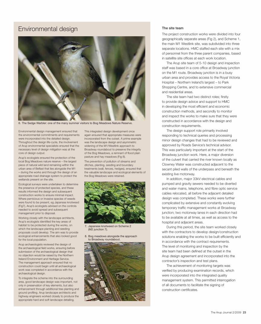
23The Arup Journal 2/2009
The site team
The project construction works were divided into four
geographically separate areas (Fig 2), and Scheme 1,
the main M1 Westlink site, was subdivided into three
separate locations. HMC staffed each site with a mix
of personnel from the three parent companies, based
in satellite site offices at each work location.
The Arup site team of 5-10 design and inspection
staff was based in a core office at Broadway junction
on the M1 route. Broadway junction is in a busy
urban area and provides access to the Royal Victoria
Hospital – Northern Ireland’s largest – to Park
Shopping Centre, and to extensive commercial
and residential areas.
The site team had two distinct roles; firstly
to provide design advice and support to HMC
in developing the most efficient and economic
construction methods, and secondly to monitor
and inspect the works to make sure that they were
constructed in accordance with the design and
construction requirements.
The design support role primarily involved
responding to technical queries and processing
minor design changes that had to be reviewed and
approved by Roads Service’s technical advisor.
This was particularly important at the start of the
Broadway junction work. Here, a major diversion
of the culvert that carried the river known locally as
Clowney Water was constructed adjacent to the
secant piled walls of the underpass and beneath the
existing live motorway.
In addition, major 33kV electrical cables and
pumped and gravity sewers needed to be diverted
and water mains, telephone, and fibre optic service
cables relocated, all before the adjacent detailed
design was completed. These works were further
complicated by extensive and constantly evolving
temporary traffic management works at Broadway
junction; two motorway lanes in each direction had
to be available at all times, as well as access to the
hospital and adjacent areas.
During this period, the site team worked closely
with the contractors to develop design/construction
solutions enabling the works to be built efficiently and
in accordance with the contract requirements.
The level of monitoring and inspection by the
site team had been defined at the outset in the
Arup design agreement and incorporated into the
contractor’s inspection and test plans.
The achievement of monitoring targets was
verified by producing examination records, which
were incorporated into the integrated quality
management system. This permitted interrogation
of all documents to facilitate the signing of
construction certificates.
Environmental design management ensured that
the environmental commitments and requirements
were incorporated into the detailed design.
Throughout the design life-cycle, the involvement
of Arup environmental specialists ensured that the
necessary level of design mitigation was at the
core of design output.
Arup’s ecologists ensured the protection of the
local Bog Meadows nature reserve – the largest
piece of natural wild land remaining within the
urban area of Belfast that lies alongside the M1
– during the works and through the design of an
appropriate road drainage system to protect the
wetlands present on the site.
Ecological surveys were undertaken to determine
the presence of protected species, and these
results informed the design and subsequent
construction works to ensure minimal impact.
Where pernicious or invasive species of weeds
were found to be present, eg Japanese knotweed
(Fig7), Arup’s ecologists advised on the controls
needed to avoid spread and subsequent
management prior to disposal.
Working closely with the landscape architects,
Arup’s ecologists identified the key areas of
habitat to be protected during the works, on
which the landscape planting and seeding
proposals could develop. The aim was to provide
ecological enhancements that also looked good
for the local population.
Arup archaeologists reviewed the design of
the archaeological field works, ensuring before
submission of the archaeological design that
no objection would be raised by the Northern
Ireland Environment and Heritage Service.
The management approach ensured that no
construction could begin until all archaeological
work was completed in accordance with the
archaeological design.
To integrate the scheme into the surrounding
area, good landscape design was important, not
only in preservation of key elements, but also
enhancement through additional tree planting and
ground profiling. Arup landscape architects and
highway engineers worked closely to produce the
appropriate hard and soft landscape detailing.
This integrated design development once
again ensured that appropriate measures were
incorporated from the outset. A prime example
was the landscape design and asymmetric
widening of the M1/Westlink approach to
Broadway roundabout to preserve the integrity
of the Bog Meadows, a remnant of flood plain
pasture and hay meadows (Fig 8).
The prevention of pollution of streams and
ditches, planting, seeding and boundary
treatments (wall, fences, hedges), ensured that
the valuable landscape and ecological elements of
the Bog Meadows were retained.
Environmental design
7. Japanese knotweed on Scheme 2 (M2 junction 7).
8. Bog meadows alongside the approach to Broadway roundabout.
6. The Sedge Warbler: one of the many summer visitors to Bog Meadows Nature Reserve.
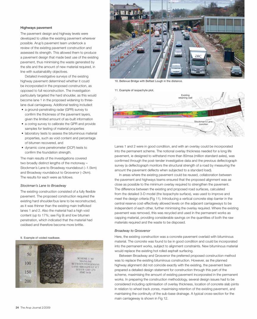
24 The Arup Journal 2/2009
Lanes 1 and 2 were in good condition, and with an overlay could be incorporated
into the permanent scheme. The notional overlay thickness needed for a long life
pavement, ie designed to withstand more than 80msa (million standard axles), was
confirmed through the post-tender investigative data and the previous deflectograph
survey (a deflectograph monitors the structural strength of a road by measuring the
amount the pavement deflects when subjected to a standard load).
In areas where the existing pavement could be reused, collaboration between
the pavement and highways teams ensured that the proposed alignment was as
close as possible to the minimum overlay required to strengthen the pavement.
The difference between the existing and proposed road surfaces, calculated
from the detailed 3-D model (the Isopachyte surface), was used to improve and
meet the design criteria (Fig 11). Introducing a vertical concrete step barrier in the
central reserve cost-effectively allowed levels on the adjacent carriageways to be
independent of each other, further minimising the overlay required. Where the existing
pavement was removed, this was recycled and used in the permanent works as
capping material, providing considerable savings on the quantities of both the raw
materials required and the waste to be disposed.
Broadway to Grosvenor
Here, the existing construction was a concrete pavement overlaid with bituminous
material. The concrete was found to be in good condition and could be incorporated
into the permanent works, subject to alignment constraints. New bituminous material
would replace the existing hot rolled asphalt surfacing.
Between Broadway and Grosvenor the preferred proposed construction method
was to replace the existing bituminous construction. However, as the planned
highway alignment did not coincide exactly with the existing, the pavement team
prepared a detailed design statement for construction through this part of the
scheme, maximising the amount of existing pavement incorporated in the permanent
works. In preparing the construction methodology, several design issues had to be
considered including optimisation of overlay thickness, location of concrete slab joints
in relation to wheel track zones, maximising retention of the existing pavement, and
maintaining the continuity of the sub-base drainage. A typical cross-section for the
main carriageway is shown in Fig 12.
Highways pavement
The pavement design and highway levels were
developed to utilise the existing pavement wherever
possible. Arup’s pavement team undertook a
review of the existing pavement construction and
assessed its strength. This allowed them to produce
a pavement design that made best use of the existing
pavement, thus minimising the waste generated by
the site and the amount of new material required, in
line with sustainability objectives.
Detailed investigative surveys of the existing
highway pavement determined whether it could
be incorporated in the proposed construction, as
opposed to full reconstruction. The investigation
particularly targeted the hard shoulder, as this would
become lane 1 in the proposed widening to three-
lane dual carriageway. Additional testing included:
confirm the thickness of the pavement layers,
given the limited amount of as-built information
samples for testing of material properties
properties, such as void content and percentage
of bitumen recovered, and
confirm the foundation strength.
The main results of the investigations covered
two broadly distinct lengths of the motorway –
Stockman’s Lane to Broadway roundabout (~1.5km)
and Broadway roundabout to Grosvenor (~2km).
The results for each were as follows.
Stockman’s Lane to Broadway
The existing construction consisted of a fully flexible
pavement. The proposed construction required the
existing hard shoulder/bus lane to be reconstructed,
as it was thinner than the existing main trafficked
lanes 1 and 2. Also the material had a high void
content (up to 17%; see Fig 9) and low bitumen
penetration, which indicated that the material had
oxidised and therefore become more brittle.
10. Bellevue Bridge with Belfast Lough in the distance.
9. Example of voided roadbase.
11. Example of isopachyte plot.
Stockman’s Lane Junction
Existingretaining wall

25The Arup Journal 2/2009
The M1-Westlink Scheme 1 ground engineering
works were concentrated on the three main
junctions: Stockman’s Lane roundabout at the south
end; Broadway junction in the middle of the route;
and Grosvenor Road junction at the city end.
Much of the alignment is constructed over sleech,
the thickness of which exceeds 8m at Broadway
junction and Grosvenor Road junction. These alluvial
deposits are underlain by stiff glacial clays and dense
sands which in turn rest on sandstone bedrock, and
dolomitic intrusions are encountered around Roden
Street. Depth to bedrock varies between 12m at
Stockman’s Lane and 25m at the city end of the site.
Groundwater is found at 1-2m below original ground
level and flows across the alignment from the higher
ground at the west towards the city centre.
Three stages of ground investigation were
undertaken: a pre-tender phase, a second during the
tender process, and a third following contract award.
The last of these was specified by Arup and focused
on obtaining:
(1) a better understanding of groundwater flows at
Broadway junction, where the deep underpass could
potentially act as a subsurface dam
(2) the variation in thickness and the engineering
properties of the sleech for embankment design at
Grosvenor Road junction and Roden Street, and
(3) the depth to, and quality of, bedrock at the
principal structures, so as to inform the pile design.
A pump test was designed for Broadway junction.
A local ground investigation contractor executed the
work and Arup hydrogeologists in Leeds prepared a
hydrogeological report.
Ground engineering
Belfast, like many cities, was built where it was due to the needs of trade, and as with
many port cities, this resulted in it being constructed on poor ground. The underlying
soft and compressible alluvial silt locally known as “sleech” influenced Belfast’s
development. Sleech was mentioned in the BBC’s popular television programme
Coast, which included a quote from the late 18th century that Belfast was “a poor
place to build a city, but a great place to site one”2. The city’s historic buildings of
the 19th and early 20th century were mostly constructed on timber piles taking the
foundation loads down through the sleech to the underlying till and bedrock.
New pavement construction
TSCS (thin surface course system) Bituminous binder course Bituminous base
Existing CRCR concrete to remain Existing sub-base below CRCR pavement Existing ground level
Sub-base
Existing CRCRto be removed
Thick pavementoverlay
150mm minimum below undersideof existing CRCR slab
Existing CRCR (continuously reinforcedconcrete roadbase) to be removed
Thin pavementoverlay
New pavementconstruction
508mm
L
91mm
1.0m
0 5.0m
1.0m
0
176mm
343mm
13. Scheme 3 under construction.
12. Typical cross-section between Broadway and Grosvenor.
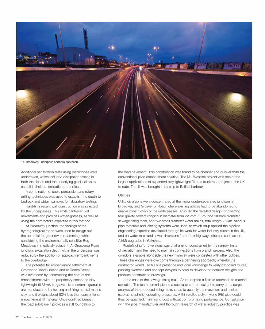
26 The Arup Journal 2/2009
the road pavement. This construction was found to be cheaper and quicker than the
conventional piled embankment solution. The M1-Westlink project was one of the
largest applications of expanded clay lightweight fill on a trunk road project in the UK
to date. The fill was brought in by ship to Belfast harbour.
Utilities
Utility diversions were concentrated at the major grade-separated junctions at
Broadway and Grosvenor Road, where existing utilities had to be abandoned to
enable construction of the underpasses. Arup did the detailed design for diverting
four gravity sewers ranging in diameter from 225mm-1.5m, one 900mm diameter
sewage rising main, and two small diameter water mains, total length 2.2km. Various
pipe materials and jointing systems were used, to which Arup applied the pipeline
engineering expertise developed through its work for water industry clients in the UK,
and on water main and sewer diversions from other highway schemes such as the
A1(M) upgrades in Yorkshire.
Routefinding for diversions was challenging, constrained by the narrow limits
of deviation and the need to maintain connections from branch sewers. Also, the
corridors available alongside the new highway were congested with other utilities.
These challenges were overcome through a partnering approach, whereby the
contractor would use his site presence and local knowledge to verify proposed routes,
passing sketches and concept designs to Arup to develop the detailed designs and
produce construction drawings.
In the case of the sewage rising main, Arup adopted a flexible approach to material
selection. The team commissioned a specialist sub-consultant to carry out a surge
analysis of the proposed rising main, so as to quantify the maximum and minimum
(sub-atmospheric) operating pressures. A thin-walled polyethylene (PE) pipe could
thus be specified, minimising cost without compromising performance. Consultation
with the pipe manufacturer and thorough research of water industry practice was
Additional penetration tests using piezocones were
undertaken, which included dissipation testing in
both the sleech and the underlying glacial clays to
establish their consolidation properties.
A combination of cable percussion and rotary
drilling techniques was used to establish the depth to
bedrock and obtain samples for laboratory testing.
Hard/firm secant wall construction was selected
for the underpasses. This limits cantilever wall
movements and provides watertightness, as well as
using the contractor’s expertise in this method.
At Broadway junction, the findings of the
hydrogeological report were used to design out
the potential for groundwater damming, while
considering the environmentally sensitive Bog
Meadows immediately adjacent. At Grosvenor Road
junction, excavation depth within the underpass was
reduced by the addition of approach embankments
to the overbridge.
The potential for embankment settlement at
Grosvenor Road junction and at Roden Street
was overcome by constructing the core of the
embankments with the proprietary expanded clay
lightweight fill Maxit. Its gravel-sized ceramic granules
are manufactured by heating and firing natural marine
clay, and it weighs about 80% less than conventional
embankment fill material. Once confined beneath
the road sub-base it provides a stiff foundation to
14. Broadway underpass northern approach.
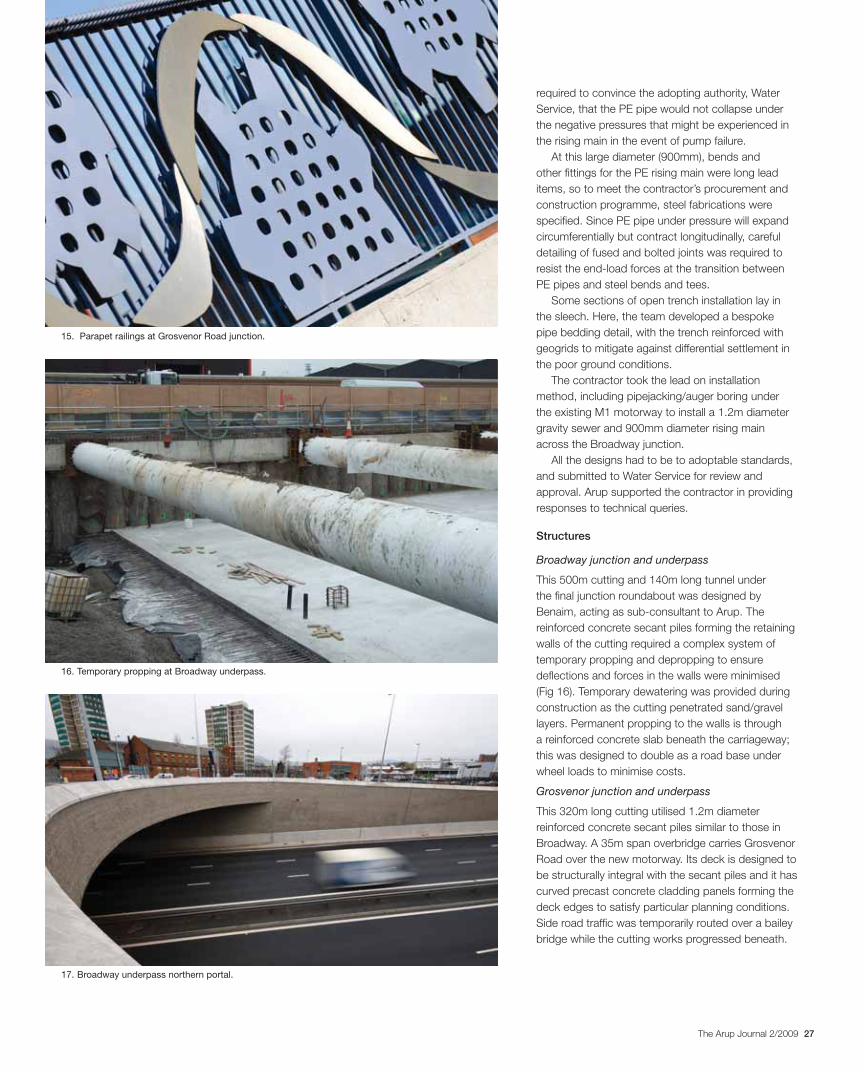
27The Arup Journal 2/2009
15. Parapet railings at Grosvenor Road junction.
required to convince the adopting authority, Water
Service, that the PE pipe would not collapse under
the negative pressures that might be experienced in
the rising main in the event of pump failure.
At this large diameter (900mm), bends and
other fittings for the PE rising main were long lead
items, so to meet the contractor’s procurement and
construction programme, steel fabrications were
specified. Since PE pipe under pressure will expand
circumferentially but contract longitudinally, careful
detailing of fused and bolted joints was required to
resist the end-load forces at the transition between
PE pipes and steel bends and tees.
Some sections of open trench installation lay in
the sleech. Here, the team developed a bespoke
pipe bedding detail, with the trench reinforced with
geogrids to mitigate against differential settlement in
the poor ground conditions.
The contractor took the lead on installation
method, including pipejacking/auger boring under
the existing M1 motorway to install a 1.2m diameter
gravity sewer and 900mm diameter rising main
across the Broadway junction.
All the designs had to be to adoptable standards,
and submitted to Water Service for review and
approval. Arup supported the contractor in providing
responses to technical queries.
Structures
Broadway junction and underpass
This 500m cutting and 140m long tunnel under
the final junction roundabout was designed by
Benaim, acting as sub-consultant to Arup. The
reinforced concrete secant piles forming the retaining
walls of the cutting required a complex system of
temporary propping and depropping to ensure
deflections and forces in the walls were minimised
(Fig 16). Temporary dewatering was provided during
construction as the cutting penetrated sand/gravel
layers. Permanent propping to the walls is through
a reinforced concrete slab beneath the carriageway;
this was designed to double as a road base under
wheel loads to minimise costs.
Grosvenor junction and underpass
This 320m long cutting utilised 1.2m diameter
reinforced concrete secant piles similar to those in
Broadway. A 35m span overbridge carries Grosvenor
Road over the new motorway. Its deck is designed to
be structurally integral with the secant piles and it has
curved precast concrete cladding panels forming the
deck edges to satisfy particular planning conditions.
Side road traffic was temporarily routed over a bailey
bridge while the cutting works progressed beneath.
16. Temporary propping at Broadway underpass.
17. Broadway underpass northern portal.
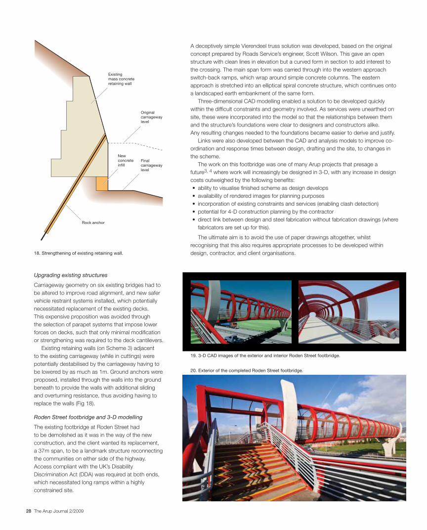
28 The Arup Journal 2/2009
A deceptively simple Vierendeel truss solution was developed, based on the original
concept prepared by Roads Service’s engineer, Scott Wilson. This gave an open
structure with clean lines in elevation but a curved form in section to add interest to
the crossing. The main span form was carried through into the western approach
switch-back ramps, which wrap around simple concrete columns. The eastern
approach is stretched into an elliptical spiral concrete structure, which continues onto
a landscaped earth embankment of the same form.
Three-dimensional CAD modelling enabled a solution to be developed quickly
within the difficult constraints and geometry involved. As services were unearthed on
site, these were incorporated into the model so that the relationships between them
and the structure’s foundations were clear to designers and constructors alike.
Any resulting changes needed to the foundations became easier to derive and justify.
Links were also developed between the CAD and analysis models to improve co-
ordination and response times between design, drafting and the site, to changes in
the scheme.
The work on this footbridge was one of many Arup projects that presage a
future3, 4 where work will increasingly be designed in 3-D, with any increase in design
costs outweighed by the following benefits:
fabricators are set up for this).
The ultimate aim is to avoid the use of paper drawings altogether, whilst
recognising that this also requires appropriate processes to be developed within
design, contractor, and client organisations.
Upgrading existing structures
Carriageway geometry on six existing bridges had to
be altered to improve road alignment, and new safer
vehicle restraint systems installed, which potentially
necessitated replacement of the existing decks.
This expensive proposition was avoided through
the selection of parapet systems that impose lower
forces on decks, such that only minimal modification
or strengthening was required to the deck cantilevers.
Existing retaining walls (on Scheme 3) adjacent
to the existing carriageway (while in cuttings) were
potentially destabilised by the carriageway having to
be lowered by as much as 1m. Ground anchors were
proposed, installed through the walls into the ground
beneath to provide the walls with additional sliding
and overturning resistance, thus avoiding having to
replace the walls (Fig 18).
Roden Street footbridge and 3-D modelling
The existing footbridge at Roden Street had
to be demolished as it was in the way of the new
construction, and the client wanted its replacement,
a 37m span, to be a landmark structure reconnecting
the communities on either side of the highway.
Access compliant with the UK’s Disability
Discrimination Act (DDA) was required at both ends,
which necessitated long ramps within a highly
constrained site.
20. Exterior of the completed Roden Street footbridge.
19. 3-D CAD images of the exterior and interior Roden Street footbridge.
Existingmass concreteretaining wall
Originalcarriagewaylevel
Finalcarriagewaylevel
Newconcreteinfill
Rock anchor
18. Strengthening of existing retaining wall.
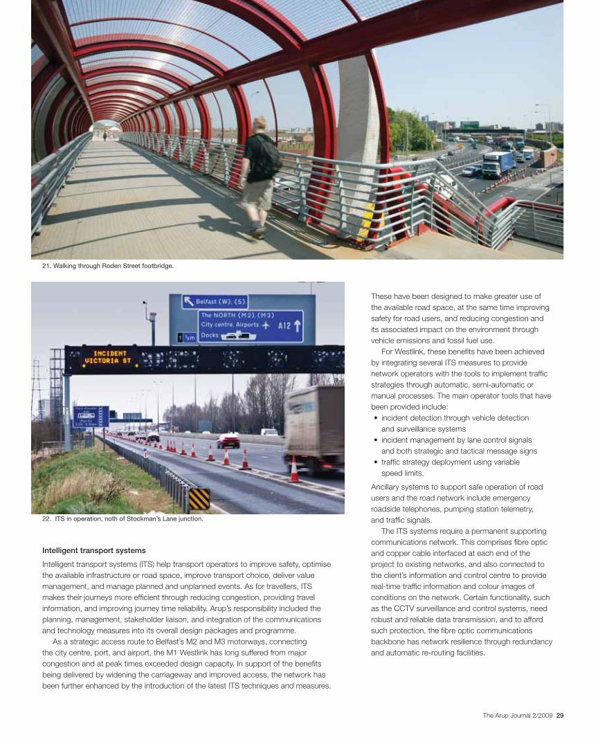
29The Arup Journal 2/2009
These have been designed to make greater use of
the available road space, at the same time improving
safety for road users, and reducing congestion and
its associated impact on the environment through
vehicle emissions and fossil fuel use.
For Westlink, these benefits have been achieved
by integrating several ITS measures to provide
network operators with the tools to implement traffic
strategies through automatic, semi-automatic or
manual processes. The main operator tools that have
been provided include:
and surveillance systems
and both strategic and tactical message signs
speed limits.
Ancillary systems to support safe operation of road
users and the road network include emergency
roadside telephones, pumping station telemetry,
and traffic signals.
The ITS systems require a permanent supporting
communications network. This comprises fibre optic
and copper cable interfaced at each end of the
project to existing networks, and also connected to
the client’s information and control centre to provide
real-time traffic information and colour images of
conditions on the network. Certain functionality, such
as the CCTV surveillance and control systems, need
robust and reliable data transmission, and to afford
such protection, the fibre optic communications
backbone has network resilience through redundancy
and automatic re-routing facilities.
Intelligent transport systems
Intelligent transport systems (ITS) help transport operators to improve safety, optimise
the available infrastructure or road space, improve transport choice, deliver value
management, and manage planned and unplanned events. As for travellers, ITS
makes their journeys more efficient through reducing congestion, providing travel
information, and improving journey time reliability. Arup’s responsibility included the
planning, management, stakeholder liaison, and integration of the communications
and technology measures into its overall design packages and programme.
As a strategic access route to Belfast’s M2 and M3 motorways, connecting
the city centre, port, and airport, the M1 Westlink has long suffered from major
congestion and at peak times exceeded design capacity. In support of the benefits
being delivered by widening the carriageway and improved access, the network has
been further enhanced by the introduction of the latest ITS techniques and measures.
22. ITS in operation, noth of Stockman’s Lane junction.
21. Walking through Roden Street footbridge.
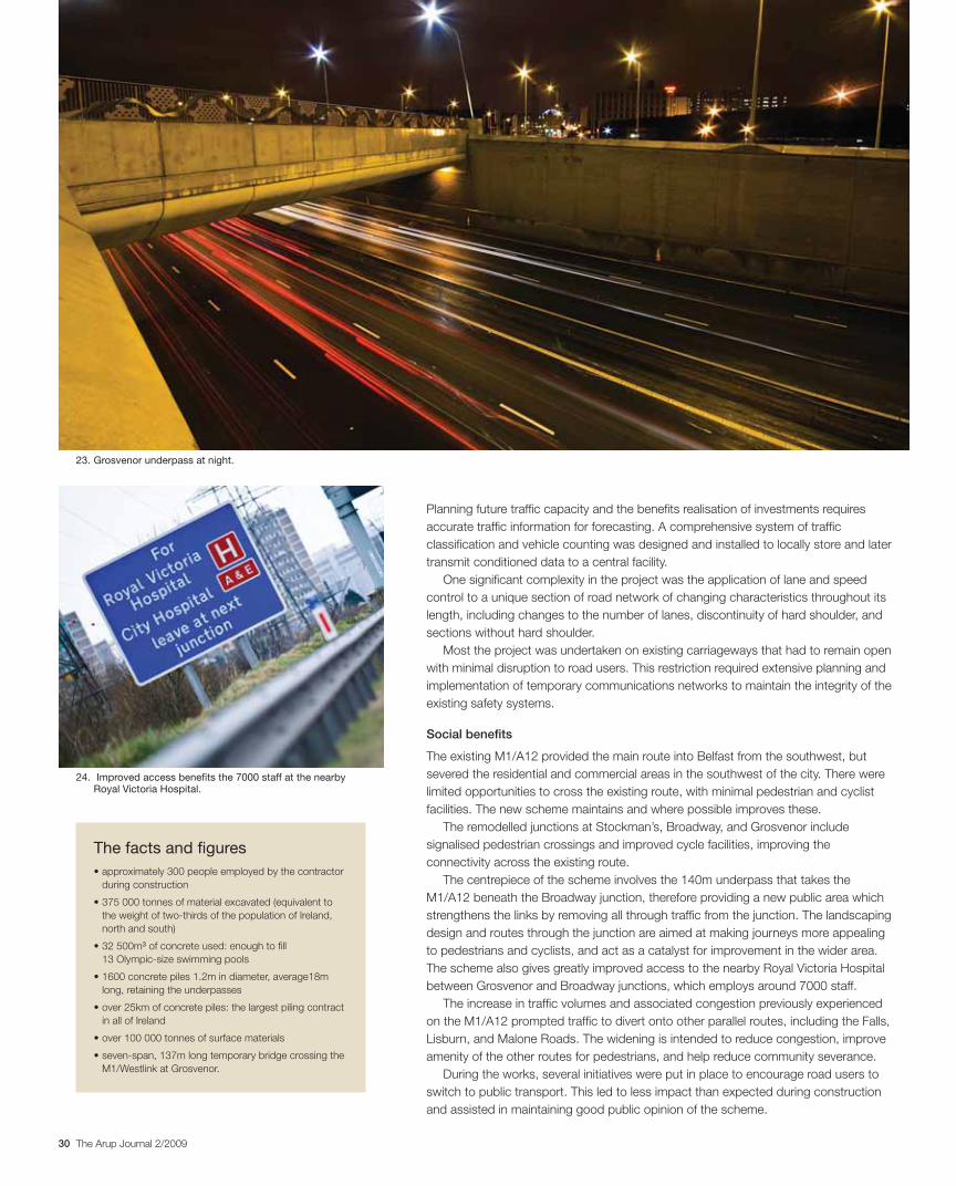
30 The Arup Journal 2/2009
Planning future traffic capacity and the benefits realisation of investments requires
accurate traffic information for forecasting. A comprehensive system of traffic
classification and vehicle counting was designed and installed to locally store and later
transmit conditioned data to a central facility.
One significant complexity in the project was the application of lane and speed
control to a unique section of road network of changing characteristics throughout its
length, including changes to the number of lanes, discontinuity of hard shoulder, and
sections without hard shoulder.
Most the project was undertaken on existing carriageways that had to remain open
with minimal disruption to road users. This restriction required extensive planning and
implementation of temporary communications networks to maintain the integrity of the
existing safety systems.
Social benefits
The existing M1/A12 provided the main route into Belfast from the southwest, but
severed the residential and commercial areas in the southwest of the city. There were
limited opportunities to cross the existing route, with minimal pedestrian and cyclist
facilities. The new scheme maintains and where possible improves these.
The remodelled junctions at Stockman’s, Broadway, and Grosvenor include
signalised pedestrian crossings and improved cycle facilities, improving the
connectivity across the existing route.
The centrepiece of the scheme involves the 140m underpass that takes the
M1/A12 beneath the Broadway junction, therefore providing a new public area which
strengthens the links by removing all through traffic from the junction. The landscaping
design and routes through the junction are aimed at making journeys more appealing
to pedestrians and cyclists, and act as a catalyst for improvement in the wider area.
The scheme also gives greatly improved access to the nearby Royal Victoria Hospital
between Grosvenor and Broadway junctions, which employs around 7000 staff.
The increase in traffic volumes and associated congestion previously experienced
on the M1/A12 prompted traffic to divert onto other parallel routes, including the Falls,
Lisburn, and Malone Roads. The widening is intended to reduce congestion, improve
amenity of the other routes for pedestrians, and help reduce community severance.
During the works, several initiatives were put in place to encourage road users to
switch to public transport. This led to less impact than expected during construction
and assisted in maintaining good public opinion of the scheme.
24. Improved access benefits the 7000 staff at the nearby Royal Victoria Hospital.
23. Grosvenor underpass at night.
The facts and figures
during construction
the weight of two-thirds of the population of Ireland,
north and south)
3 of concrete used: enough to fill
13 Olympic-size swimming pools
long, retaining the underpasses
in all of Ireland
M1/Westlink at Grosvenor.
31The Arup Journal 2/2009
The other works associated with Schemes 2 and
4 have been undertaken in parallel with the major
works on the M1/A12 and M2. Work on new M2 slip
roads at the Antrim Hospital junction started in late
2006 and was completed mid-2007. The other safety
barrier and motorway communications works which
form Scheme 4 are due to be completed in early
2009 alongside Schemes 1 and 3. Overall, the entire
project was completed six months ahead of the
original construction programme.
Economic benefits
The M1 motorway and A12 Westlink form part of the Eastern Seaboard Key Transport
Corridor which provides high capacity road and rail links between Belfast and Dublin
and onward towards Larne, Warrenpoint, and Rosslare. The link also forms part of
European route E-01 and is thus of strategic importance to Northern Ireland and the
wider Europe. As Northern Ireland’s capital, Belfast depends on road transport to
move most of the goods to and from its port.
In recent years this route has been characterised by its significant congestion
resulting from at-grade junctions and lack of lane capacity. This not only disrupted
though traffic but impacted on traffic entering and exiting the city centre. The
completed project addresses each of these issues, offering free-flowing access
around the A12 Westlink and better access to the city centre. With the completion
of the York Street interchange in the centre of Belfast, which is planned to follow, the
scheme will ultimately provide a complete free flowing link between the M1, M2 and
M3 corridors. The junction strategy adopted on the scheme will also help to improve
journey times and journey time reliability, and will deliver economic benefits associated
with this reduction in congestion.
The scheme includes bus lane facilities which utilise the hard shoulder of the M1
during peak periods to ensure that the economic benefits of fast and efficient public
transport are realised. This also includes a dedicated bus-only link from Broadway
roundabout to Belfast central bus and rail stations.
Progress
Work started on Scheme 1 in early 2006, with the construction of the culverts to allow
the diversion of the watercourses at Broadway and the construction of a temporary
bridge at Grosvenor to keep Grosvenor Road open during the works. The first major
milestone was reached in October 2007 when the new Grosvenor Road bridge was
opened to the public, with the remainder of the junction being completed in March
2008. The second major milestone was the opening of the new Broadway underpass
in July 2008. The remainder of Scheme 1 was completed in early 2009.
Work started in April 2007 to widen the M2 motorway and replace three existing
overbridges including Hightown bridge. This was completed and opened in
September 2008.
Dom Ainger is a senior engineer in Arup’s Leeds office.
He led the design of water main and sewer diversions on
the M1/Westlink project.
John Border is an Associate Director of Arup in the
Midlands Campus. He was Project Manager for the M1/
Westlink project.
Chris Caves is an Associate Director of Arup in
the Belfast office. He was Project Manager for the
construction phase of M1/Westlink.
Paola Dalla Valle is an engineer at the Midlands
Campus. She was a member of the highways pavement
design team on M1/Westlink.
Chris Furneaux is an engineer in Arup’s Midlands
Campus. He was Assistant Project Manager and
comms/civil co-ordinator on M1/Westlink.
Tim Gammons is a Director of Arup in the Leeds office.
He led the intelligent transport systems design for M1/
Westlink.
John Griffiths is a senior engineer in Arup’s Midlands
Campus. He was a member of the highways pavement
design team for M1/Westlink.
Deepak Jayaram is an Associate Director of Arup in
the Midlands Campus. He led the structural engineering
design on M1/Westlink.
Ray Kendal is an associate of Arup Consulting
Engineers in Dublin. He was the designer’s site
representative (DSR) on M1/Westlink.
Ronnie Palmer is an Associate of Arup in the Midlands
Campus. He led the environmental mitigation team on
M1/Westlink.
Alan Phear is an Associate Director of Arup in the
Midlands Campus. He led the ground engineering design
on M1/Westlink.
Andy Ross is an engineer in Arup’s Glasgow office.
He was a member of the ground engineering design
team on M1/Westlink.
Guy Stabler is a senior engineer in the Midlands
Campus. He co-ordinated the structural engineering
design on M1/Westlink.
Credits
Client: Highway Management Construction Ltd Lead designer (highways, structures, drainage, ground engineering, traffic signalling, environmental mitigation, motorway communications, and site supervision): Arup - Mark Adams, Dom Ainger, Clive Aubrey, Maria Batko, Jaswant Birdi, Kim
Blackmore, John Border, Grainne Breen, Adam Bryce, Alex Bryson, Neil Cameron, Savina Carluccio,
Desiree Carolus, Stephen Carter, Chris Caves, Harry Clements, Mark Cowan, Lewis Cowley, Nathan
Crabtree, Paul Cruise, Wilma Cruz, Paola Dalla Valle, Mark Darlow, Andy Davidson, Lee Davison,
Simon Dean, Barry Dooley, Ana Duarte, David Edwards, Nick Ferro, Rob Franklin, Russell Fraser,
Marek Fuks, Chris Furneaux, Lee Gill, Anna Gracey, Naomi Green, Geoff Griffiths, John Griffiths, Stuart
Haden, Mick Hall, John Hammon, Simon Harris, Russell Harrison, Steve Henry, Oliver Hofmann,
Andrew Huckson. Gareth Hughes, David Hurton, Catherine James, Deepak Jayaram, Daniel Jirasko,
Irfanullah Kahn, Matt Knight, Linus Kuncewicz, Michael Larvin, Charlotte Lawson, Andrew Lloyd, Chris
Madigan, Tony Marshall, Karen Mayo, David McShane, Silole Menezes, Juliet Mian, Nette Mijares, Maria
Mingallon-Villajos, Clayton Mitchell, Gavin Newlands,Oliver Nicholas, Joanna Nobbs, Nick O’Riordan,
Diji Oludipo, Mazen Omran, Miklos Orova, Simon Owen, Keith Padbury, Michael Page, Ronnie Palmer,
Hemal Patel, Michael Penfold, Alan Phear, David Pinto, Daniel Potts, Richard Price, Tom Price, Mario
Querol, Andrew Ridley, Andy Ross, Adriana Santos, Diane Sadleir, Justice Sechele, Malcolm Sim,
Mark Skinner, Guy Stabler, David Stevens, Thomas Stock, Paul Summers, Suresh Tank, Hermione
Thompson, Steven Thompson, Cliff Topham-Steele, Andrew Turner, Michael Tyrrell, Jan Valenta, Martin
Vanicek, Stuart Walker, Wen Xiao Wang, Mark Waterhouse, Pete Weston, David Whittles, Craig Wiggins,
Eric Wilde, Pete Wilkie, Heather Wilson, Lukasz Wojnarski, David Wolliston, Roger Wong, Ying Zhou
Subconsultants to Arup – Broadway junction and underpass design: Benaim Communications design: Serco Integrated Transport Traffic signal design: Siemens Street lighting design: Lighting
Consultancy and Design Services Road safety auditor: WA Fairhurst Category 3 structure checker:Halcrow Main contractor: Highway Management Construction (JV of John Graham (Dromore)/
Northstone (NI) Ltd/Bilfinger Berger Illustrations: 1, 11, 13-15, 17, 22-24 Andrew Hazard; 2-5, 12,
18 Nigel Whale; 6 Anna Kravchuk/Dreamstime; 7, 9, 10, 16, 19 Arup; 8 Department for Regional
Development Roads Service; 20, 21 ©Stephen Leckie, Scott Wilson.
References
(1) BALMER, D, et al. M6 Toll. The Arup Journal, 40(1), pp45-55,
1/2005.
(2) SOMERVILLE, C. Coast: the journey continues. BBC Books,
2006.
(3) BAILEY, P et al. The Virtual Building. The Arup Journal, 43(2),
pp15-25, 2/2008.
(4) SIMONDETTI, A. Designer’s Toolkit 2020: A vision for the
design practice. The Arup Journal, 43(2), pp15-25, 2/2008.

32 The Arup Journal 2/2009
Aru
p J
apan
Celebra t ing 20 yea rs o f
Century Tower, Tokyo
1987-1991Client: Century Tower Architect: Foster and Partners
London-based structural engineering design to scheme stage of 21-storey office building with eccentric K-braced structure for seismic resistance.
Maison Hermès, Tokyo
1998-2001 Client: Hermès Japon Architect: Renzo Piano Building Workshop
SMEP scheme design and site supervision of a very slender 11-storey building, whose innovatory “stepping column” seismic-resistant design was inspired by traditional Japanese wooden pagodas (see also pp42-44).
Kansai International Airport, Osaka
1988-1994 Client: Kansai International Airport Corporation Architect: Renzo Piano Building Workshop Japan in joint venture with ADP, JAC, and Nikken Sekkei
London-based SMEP and fire engineering design of a 1.6km long, 291 000m2 terminal building on an artificial island.
The Arup Journal, 30(1), pp14-22, 1/1995.
National Theatre Okinawa, Okinawa
1998-2003 Client: Okinawa General Bureau Development Construction Architect: Shin Takamatsu Architect & Associates
Structural engineering design and site supervision for new 14 000m² national dance theatre in reinforced concrete, including two halls and educational facilities.
Museum of Fruit, Yamanashi
1992-1995 Client: Yamanashi Prefecture Architect: Itsuko Hasegawa Atelier
Full structural engineering design and site supervision for museum comprising three glazed steel shell structures up to 20m high and 50m wide, with a conservatory for growing plants.
Central Japan International Airport, Aichi
1999-2005 Client: Central Japan International Airport Architect: Nikken Sekkei in joint venture with Azusa, HOK, and Arup
Structural and façade engineering design, design review, and site supervision for airport terminal handling 17M passengers annually.
The Arup Journal, 40(3), pp50-56, 3/2005.
Osaka Maritime Museum
1993-2000 Client: Osaka Port and Harbour Authority Architect: Paul Andreu Architects with Tohata Architects & Engineers
Structural and mechanical engineering design of 70m diameter steel lattice dome, positioned offshore in Osaka Bay, and of associated onshore structures.
The Arup Journal, 36(1), pp21-27, 1/2001.
NTT DoCoMo tower, Osaka
2000-2004 Client: NTT Docomo Inc Architect: NTT Facilities
Structural and seismic engineering design of a 1650 tonne, 145.4m tall cable-guyed steel telecommunications tower on top of a 12-storey building (see also pp45-48).
1
8
2
9
3
10
4
11
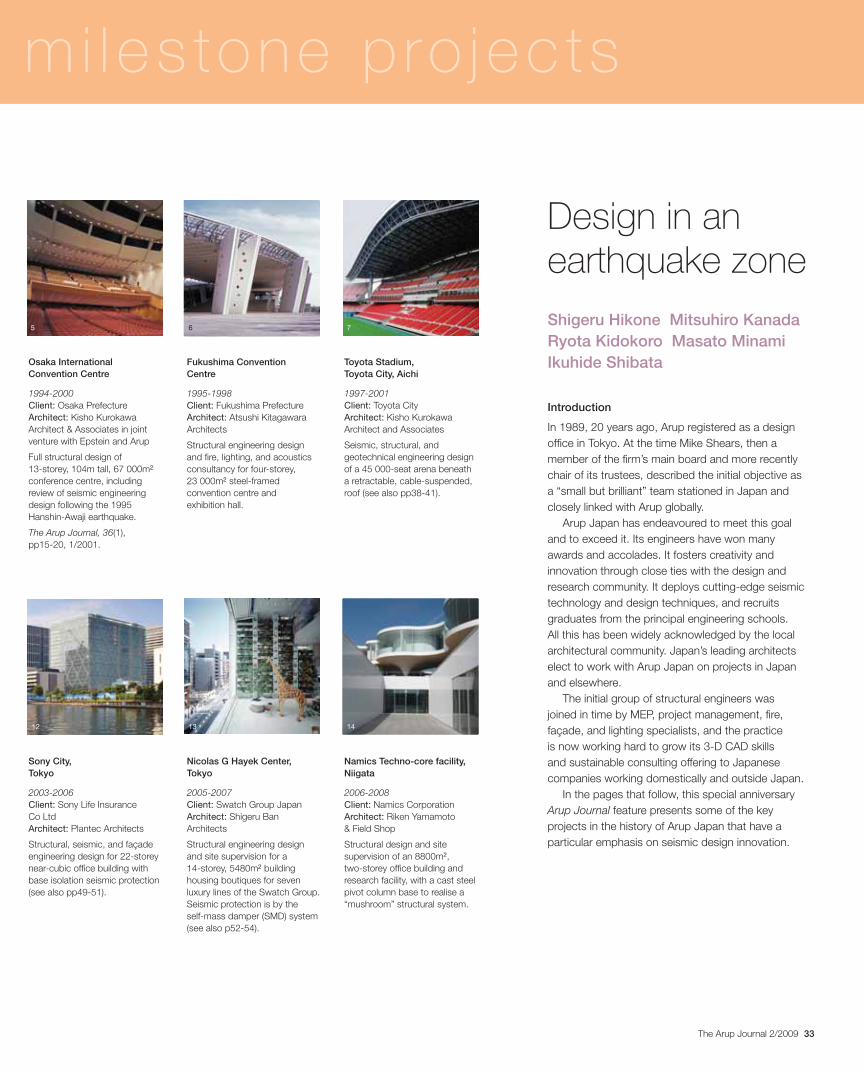
33The Arup Journal 2/2009
Introduction
In 1989, 20 years ago, Arup registered as a design office in Tokyo. At the time Mike Shears, then a member of the firm’s main board and more recently chair of its trustees, described the initial objective as a “small but brilliant” team stationed in Japan and closely linked with Arup globally.
Arup Japan has endeavoured to meet this goal and to exceed it. Its engineers have won many awards and accolades. It fosters creativity and innovation through close ties with the design and research community. It deploys cutting-edge seismic technology and design techniques, and recruits graduates from the principal engineering schools. All this has been widely acknowledged by the local architectural community. Japan’s leading architects elect to work with Arup Japan on projects in Japan and elsewhere.
The initial group of structural engineers was joined in time by MEP, project management, fire, façade, and lighting specialists, and the practice is now working hard to grow its 3-D CAD skills and sustainable consulting offering to Japanese companies working domestically and outside Japan.
In the pages that follow, this special anniversary Arup Journal feature presents some of the key projects in the history of Arup Japan that have a particular emphasis on seismic design innovation.
mi les tone p ro jec ts
Design in an earthquake zoneShigeru Hikone Mitsuhiro Kanada Ryota Kidokoro Masato Minami Ikuhide Shibata Osaka International
Convention Centre
1994-2000 Client: Osaka Prefecture Architect: Kisho Kurokawa Architect & Associates in joint venture with Epstein and Arup
Full structural design of 13-storey, 104m tall, 67 000m2
conference centre, including review of seismic engineering design following the 1995 Hanshin-Awaji earthquake.
The Arup Journal, 36(1), pp15-20, 1/2001.
Sony City, Tokyo
2003-2006 Client: Sony Life Insurance Co Ltd Architect: Plantec Architects
Structural, seismic, and façade engineering design for 22-storey near-cubic office building with base isolation seismic protection (see also pp49-51).
Fukushima Convention Centre
1995-1998 Client: Fukushima Prefecture Architect: Atsushi Kitagawara Architects
Structural engineering design and fire, lighting, and acoustics consultancy for four-storey, 23 000m2 steel-framed convention centre and exhibition hall.
Nicolas G Hayek Center, Tokyo
2005-2007 Client: Swatch Group Japan Architect: Shigeru Ban Architects
Structural engineering design and site supervision for a 14-storey, 5480m2 building housing boutiques for seven luxury lines of the Swatch Group. Seismic protection is by the self-mass damper (SMD) system (see also p52-54).
Toyota Stadium, Toyota City, Aichi
1997-2001 Client: Toyota City Architect: Kisho Kurokawa Architect and Associates
Seismic, structural, and geotechnical engineering design of a 45 000-seat arena beneath a retractable, cable-suspended, roof (see also pp38-41).
Namics Techno-core facility, Niigata
2006-2008 Client: Namics Corporation Architect: Riken Yamamoto & Field Shop
Structural design and site supervision of an 8800m2,two-storey office building and research facility, with a cast steel pivot column base to realise a “mushroom” structural system.
5
12
6
13
7
14
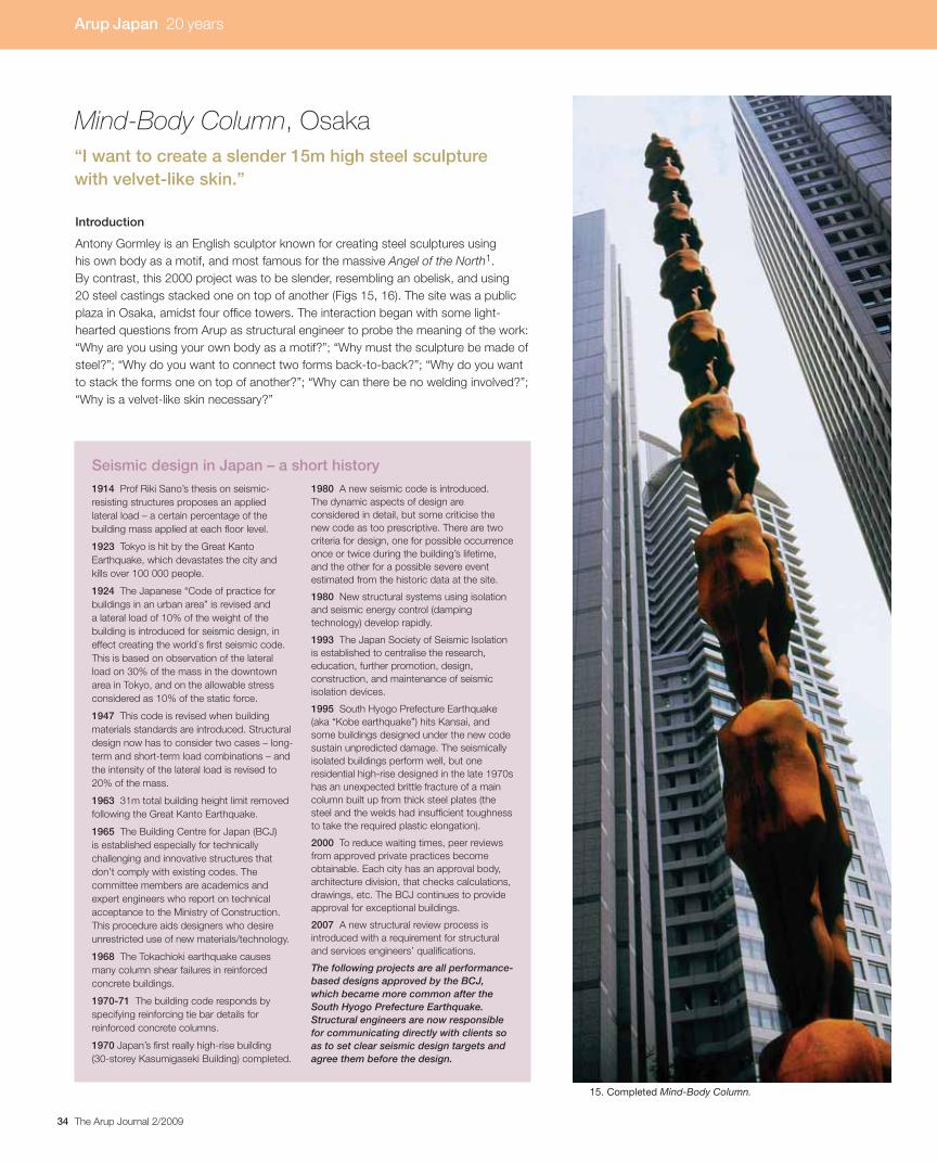
34 The Arup Journal 2/2009
Introduction
Antony Gormley is an English sculptor known for creating steel sculptures using
his own body as a motif, and most famous for the massive Angel of the North1.
By contrast, this 2000 project was to be slender, resembling an obelisk, and using
20 steel castings stacked one on top of another (Figs 15, 16). The site was a public
plaza in Osaka, amidst four office towers. The interaction began with some light-
hearted questions from Arup as structural engineer to probe the meaning of the work:
“Why are you using your own body as a motif?”; “Why must the sculpture be made of
steel?”; “Why do you want to connect two forms back-to-back?”; “Why do you want
to stack the forms one on top of another?”; “Why can there be no welding involved?”;
“Why is a velvet-like skin necessary?”
15. Completed Mind-Body Column.
Mind-Body Column, Osaka“I want to create a slender 15m high steel sculpture with velvet-like skin.”
Arup Japan 20 years
1914 Prof Riki Sano’s thesis on seismic-
resisting structures proposes an applied
lateral load – a certain percentage of the
building mass applied at each floor level.
1923 Tokyo is hit by the Great Kanto
Earthquake, which devastates the city and
kills over 100 000 people.
1924 The Japanese “Code of practice for
buildings in an urban area” is revised and
a lateral load of 10% of the weight of the
building is introduced for seismic design, in
effect creating the world`s first seismic code.
This is based on observation of the lateral
load on 30% of the mass in the downtown
area in Tokyo, and on the allowable stress
considered as 10% of the static force.
1947 This code is revised when building
materials standards are introduced. Structural
design now has to consider two cases – long-
term and short-term load combinations – and
the intensity of the lateral load is revised to
20% of the mass.
1963 31m total building height limit removed
following the Great Kanto Earthquake.
1965 The Building Centre for Japan (BCJ)
is established especially for technically
challenging and innovative structures that
don’t comply with existing codes. The
committee members are academics and
expert engineers who report on technical
acceptance to the Ministry of Construction.
This procedure aids designers who desire
unrestricted use of new materials/technology.
1968 The Tokachioki earthquake causes
many column shear failures in reinforced
concrete buildings.
1970-71 The building code responds by
specifying reinforcing tie bar details for
reinforced concrete columns.
1970 Japan’s first really high-rise building
(30-storey Kasumigaseki Building) completed.
1980 A new seismic code is introduced.
The dynamic aspects of design are
considered in detail, but some criticise the
new code as too prescriptive. There are two
criteria for design, one for possible occurrence
once or twice during the building’s lifetime,
and the other for a possible severe event
estimated from the historic data at the site.
1980 New structural systems using isolation
and seismic energy control (damping
technology) develop rapidly.
1993 The Japan Society of Seismic Isolation
is established to centralise the research,
education, further promotion, design,
construction, and maintenance of seismic
isolation devices.
1995 South Hyogo Prefecture Earthquake
(aka “Kobe earthquake”) hits Kansai, and
some buildings designed under the new code
sustain unpredicted damage. The seismically
isolated buildings perform well, but one
residential high-rise designed in the late 1970s
has an unexpected brittle fracture of a main
column built up from thick steel plates (the
steel and the welds had insufficient toughness
to take the required plastic elongation).
2000 To reduce waiting times, peer reviews
from approved private practices become
obtainable. Each city has an approval body,
architecture division, that checks calculations,
drawings, etc. The BCJ continues to provide
approval for exceptional buildings.
2007 A new structural review process is
introduced with a requirement for structural
and services engineers’ qualifications.
The following projects are all performance-based designs approved by the BCJ, which became more common after the South Hyogo Prefecture Earthquake. Structural engineers are now responsible for communicating directly with clients so as to set clear seismic design targets and agree them before the design.
Seismic design in Japan – a short history

35The Arup Journal 2/2009
FPS base isolation system
The wood form that Arup received from Gormley was
moulded exactly in his form (Fig 17). The ankle-width
is 170mm, and the distance between the axes of
each pair of opposing ankles is 265mm.
The overall height of 15.4m has a 1:90 aspect
ratio – an extremely slender proportion – and the
whole sculpture is also very heavy, at around
15 tonnes. It was clearly going to be difficult to make
it as earthquake-resistant as it needed to be in such
a seismically active country.
To solve this problem, four FPS (friction pendulum
system) isolators were installed at its base under
the pedestal. Each comprises a concave surface,
an articulated bearing, and a cover plate. In an
earthquake the bearing slides on the concave
surface, allowing the structure to move relative to the
base. FPS isolators – similar to lead-rubber or high
damping rubber bearings – cause the vibration period
of structures to change. Although dependent upon
the scale of the supported structure, FPS offers some
advantages over rubber-based bearings; it is not
affected by temperature or aging, it is durable, and
has a high vertical stiffness (Fig 19).
The FPS system reduced the response
acceleration by approximately two-thirds, so that the
sculpture would not be damaged or collapse even in
the largest earthquake. Also, to prevent uplift and to
stop the isolators being moved by wind, the pedestal
was given a weight of some 25 tons (Fig 18).
This performance-based design by Arup needed,
and was granted, special approval by Japan’s
Ministry of Construction.
The sculpture
Multistorey basement
Suspendedpodium slab
FPS baseisolator
Steelbeams
Hardlandscaping
Sculptureconnected topedestal with fullpenetration buttweld on site
Cast steelpedestal
Interference fitconnection
16. Front and side elevation.
17. Wooden model.
18. Cast steel pedestal supported by four FPS base isolators.
RE
SP
ON
SE
TO
EA
RTH
QU
AK
E = 2%
= 5%
= 10%
NATURAL VIBRATION PERIOD
Fixed base
Isolated base
19. Generic graph of response spectrum showing beneficialperiod shift and reduction in response if the structure isbase isolated.
Arup Japan 20 years

36 The Arup Journal 2/2009
Velvet-like skin
In Japan, with its harsh natural environment, base isolation and seismic control
technology are well developed, and wind and earthquake resistance did not represent
the greatest challenge. The biggest question was how to bring out the material’s
natural look, with a subtle artisan flavour.
Normally, cast pieces are produced by pouring molten steel into a sand mold.
Imprints from this leave blemishes on the outer surface, so imprint resistor is brushed
onto the mold surface beforehand. However, this in turn leaves unsightly brush marks
that reduce surface quality. In addition, water blow holes, deformations due to heat
treating, and weld flashes where separate molds are joined, are unavoidable. These
marks could have been eliminated by grinding and using adhesive metal, but that
would have spoilt the velvet skin quality.
How could a cast piece that needed no repair be created? Through simulation
and trial-and-error, the team investigated all possible production processes, moving
thereby from the realm of structural engineering into that of sculpture. Rusting of
the surface was an important quality sought by the sculptor, so in the end ordinary
structural steel was used and treated in accordance with his specification (Fig 20).
Interference fitting
The stacked figures needed robust connections, and for this the team chose
interference fitting, a method commonly used to produce marine cylinders and
camshafts. The upper torso sections were warmed by an electric heater for four hours
to 240ºC, thus widening the neck holes. The lower ankle sections were immersed for
30 minutes in -270ºC liquid nitrogen, cooling them to -100ºC with resulting shrinkage.
Each shrunken ankle could then be fit into a widened neck and then brought back to
room temperature, resulting in a secure connection (Figs 21-23).
Normal interference fittings are applied to circular sections, not elliptical as here,
so predicting prestress at the joint was difficult. The team used the analysis software
LS-DYNA 3D to simulate and study the relationship between fitting area size and
the shrinking pressure or tensile strength. Two models were made, with a contact
surface between them having a specified friction coefficient and a prestress to model
the contact pressure. The analysis results, later verified by a physical pull-out test,
enabled the final joint size to be determined. The “female” element was 93 x 150mm,
and the “male” only 1/600 larger, 93.15 x 150.25mm (Figs 24, 25).
Each cast “body” includes several different shapes, so an extraordinarily high
degree of precision was required throughout, entailing many judgements and
resolutions in every process from the mechanical production to the shrink fittings –
a particular challenge each time (Fig 26).23. Commencing shrinkage fit (fitting time two seconds).
22. Portion of connection to be inserted.
21. Interior of vertical connection before insertion.
20. Cast steel piece before machine processing.
24. Still images from the LS-DYNA tensile pull-out model show the connection between two castings being pulled apart. The results of the LS-DYNA analysis were later verified by physical testing.
-98.64-74.28-49.91-25.55-1.1823.1847.5471.9196.27
120.64145.00
Mid surface
Arup Japan 20 years

37The Arup Journal 2/2009
Mind-Body Column
The completed sculpture and its base are founded on a suspended podium slab over
a multi-storey basement. The sculpture was craned into position as a unit and field-
welded to the base.
Work on the project began in March 2000, and it was completed in June .
The artwork was named Mind-Body Column, a continuous human body moulded
from steel, symbolizing the earth itself, standing slender yet sturdy in a valley between
high-rise buildings. Orange rust runs down the velvet-like skin, a permanent but
continually changing patina (Fig 27, 28).
27. Completed Mind-Body Column.
Credits
Client: Rail City West Development, Osaka Sculptor: Anthony Gormley Structural engineer:Arup – Shigeru Hikone, Mitsuhiro Kanada, Ikuhide Shibata.
Reference
(1) BROWN, M, et al. The Angel of the North, The Arup Journal, 33(2), pp15-17, 2/1998.
25. Shrink-fitted test piece for tensile strength testing.
28.
26. Cast steel elements connected.
Arup Japan 20 years
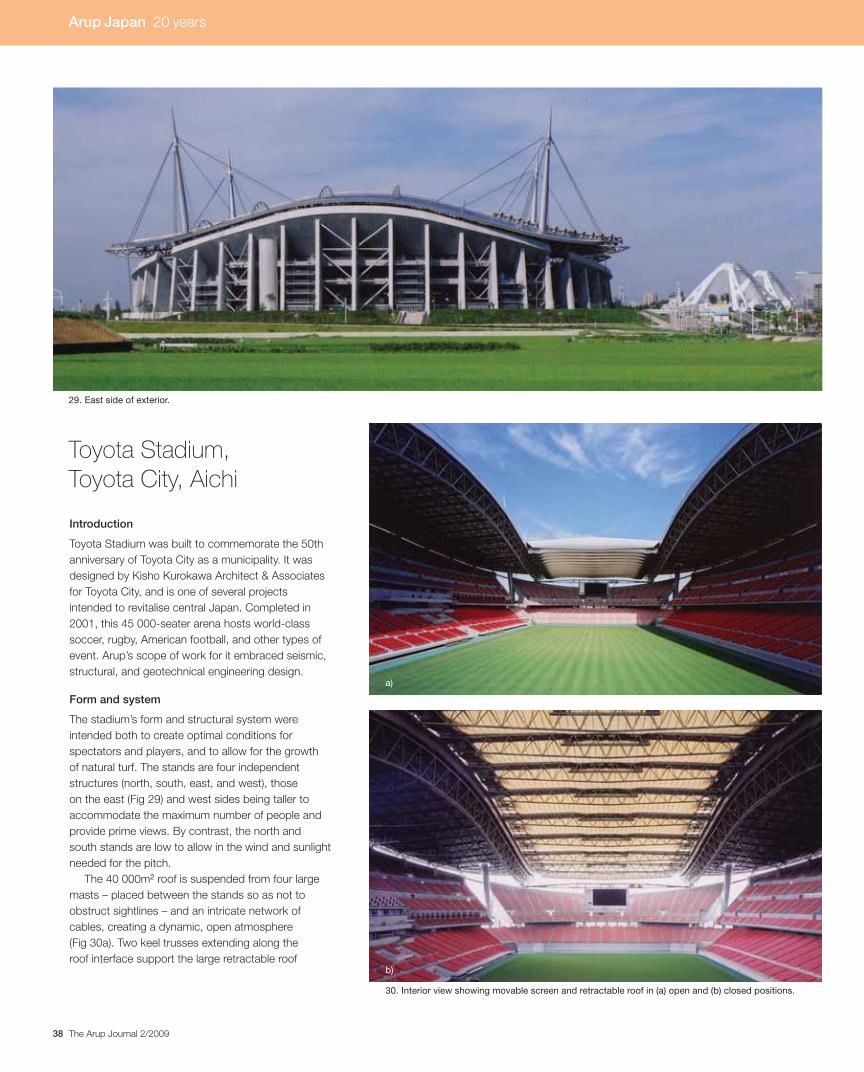
38 The Arup Journal 2/2009
Introduction
Toyota Stadium was built to commemorate the 50th
anniversary of Toyota City as a municipality. It was
designed by Kisho Kurokawa Architect & Associates
for Toyota City, and is one of several projects
intended to revitalise central Japan. Completed in
2001, this 45 000-seater arena hosts world-class
soccer, rugby, American football, and other types of
event. Arup’s scope of work for it embraced seismic,
structural, and geotechnical engineering design.
Form and system
The stadium’s form and structural system were
intended both to create optimal conditions for
spectators and players, and to allow for the growth
of natural turf. The stands are four independent
structures (north, south, east, and west), those
on the east (Fig 29) and west sides being taller to
accommodate the maximum number of people and
provide prime views. By contrast, the north and
south stands are low to allow in the wind and sunlight
needed for the pitch.
The 40 000m2 roof is suspended from four large
masts – placed between the stands so as not to
obstruct sightlines – and an intricate network of
cables, creating a dynamic, open atmosphere
(Fig 30a). Two keel trusses extending along the
roof interface support the large retractable roof
Toyota Stadium, Toyota City, Aichi
29. East side of exterior.
30. Interior view showing movable screen and retractable roof in (a) open and (b) closed positions.
a)
b)
Arup Japan 20 years
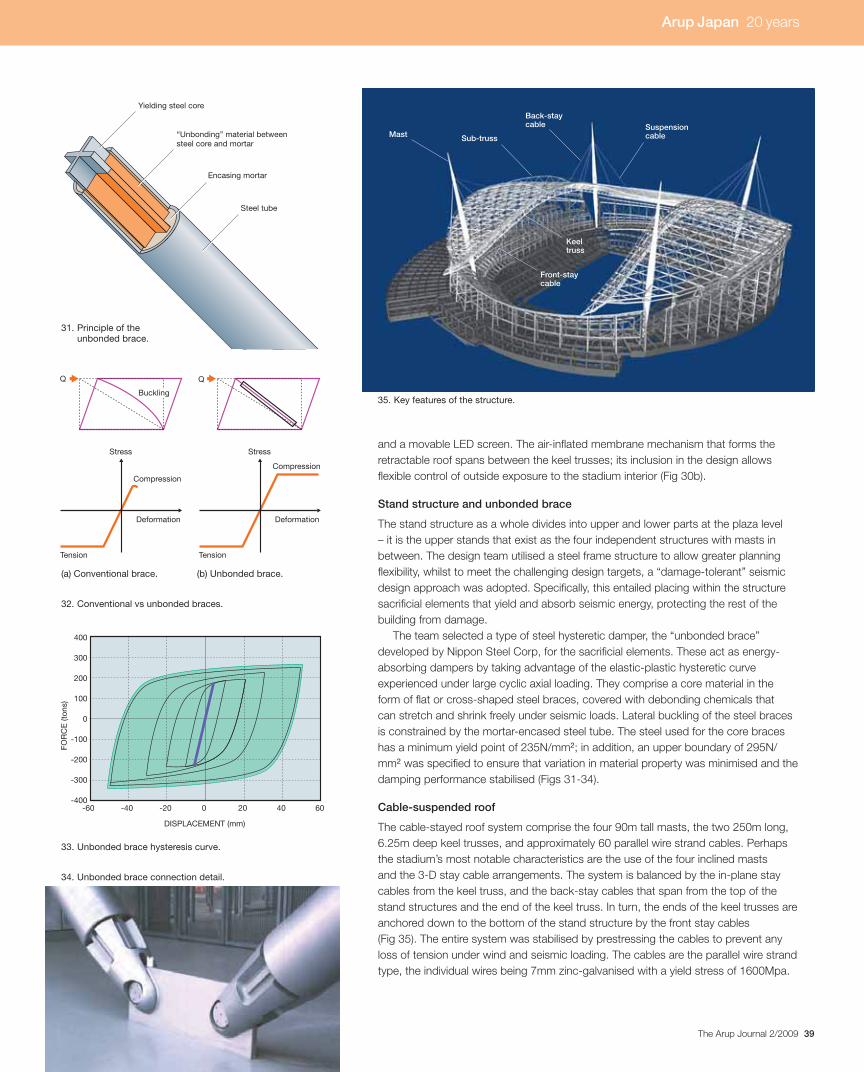
39The Arup Journal 2/2009
and a movable LED screen. The air-inflated membrane mechanism that forms theretractable roof spans between the keel trusses; its inclusion in the design allowsflexible control of outside exposure to the stadium interior (Fig 30b).
Stand structure and unbonded brace
The stand structure as a whole divides into upper and lower parts at the plaza level– it is the upper stands that exist as the four independent structures with masts inbetween. The design team utilised a steel frame structure to allow greater planningflexibility, whilst to meet the challenging design targets, a “damage-tolerant” seismicdesign approach was adopted. Specifically, this entailed placing within the structuresacrificial elements that yield and absorb seismic energy, protecting the rest of thebuilding from damage.
The team selected a type of steel hysteretic damper, the “unbonded brace”developed by Nippon Steel Corp, for the sacrificial elements. These act as energy-absorbing dampers by taking advantage of the elastic-plastic hysteretic curveexperienced under large cyclic axial loading. They comprise a core material in theform of flat or cross-shaped steel braces, covered with debonding chemicals thatcan stretch and shrink freely under seismic loads. Lateral buckling of the steel bracesis constrained by the mortar-encased steel tube. The steel used for the core braceshas a minimum yield point of 235N/mm2; in addition, an upper boundary of 295N/mm2 was specified to ensure that variation in material property was minimised and thedamping performance stabilised (Figs 31-34).
Cable-suspended roof
The cable-stayed roof system comprise the four 90m tall masts, the two 250m long,6.25m deep keel trusses, and approximately 60 parallel wire strand cables. Perhapsthe stadium’s most notable characteristics are the use of the four inclined mastsand the 3-D stay cable arrangements. The system is balanced by the in-plane staycables from the keel truss, and the back-stay cables that span from the top of thestand structures and the end of the keel truss. In turn, the ends of the keel trusses areanchored down to the bottom of the stand structure by the front stay cables(Fig 35). The entire system was stabilised by prestressing the cables to prevent anyloss of tension under wind and seismic loading. The cables are the parallel wire strandtype, the individual wires being 7mm zinc-galvanised with a yield stress of 1600Mpa.
Q Q
Stress
Deformation
Compression
Tension
Stress
Deformation
Compression
Tension
Buckling
FOR
CE
(ton
s)
DISPLACEMENT (mm)
400
300
200
100
0
-100
-200
-300
-400-60 -40 -20 0 20 40 60
35. Key features of the structure.
32. Conventional vs unbonded braces.
(a) Conventional brace. (b) Unbonded brace.
33. Unbonded brace hysteresis curve.
34. Unbonded brace connection detail.
Mast
Keeltruss
SuspensioncableSub-truss
Back-staycable
Front-staycable
Yielding steel core
Encasing mortar
Steel tube
“Unbonding” material betweensteel core and mortar
31. Principle of theunbonded brace.
Arup Japan 20 years
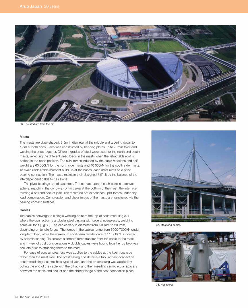
40 The Arup Journal 2/2009
Masts
The masts are cigar-shaped, 3.5m in diameter at the middle and tapering down to
1.5m at both ends. Each was constructed by bending plates up to 70mm thick and
welding the ends together. Different grades of steel were used for the north and south
masts, reflecting the different dead loads in the masts when the retractable roof is
parked in the open position. The axial forces induced by the cable reactions and self-
weight are 60 000kN for the north side masts and 40 000kN for the south side masts.
To avoid undesirable moment build-up at the bases, each mast rests on a pivot
bearing connection. The masts maintain their designed 7.5˚ tilt by the balance of the
interdependent cable forces alone.
The pivot bearings are of cast steel. The contact area of each base is a convex
sphere, matching the concave contact area at the bottom of the mast, the interface
forming a ball and socket joint. The masts do not experience uplift forces under any
load combination. Compression and shear forces of the masts are transferred via the
bearing contact surfaces.
Cables
Ten cables converge to a single working point at the top of each mast (Fig 37),
where the connection is a tubular steel casting with several nosepieces, weighing
some 40 tons (Fig 38). The cables vary in diameter from 140mm to 200mm,
depending on tensile forces. The forces in the cables range from 5000-7000kN under
long-term load, while the maximum short-term tensile force of 11 000kN is induced
by seismic loading. To achieve a smooth force transfer from the cable to the mast –
and in view of cost considerations – double cables were bound together by two-way
sockets prior to attaching them to the mast.
For ease of access, prestress was applied to the cables at the keel truss side
rather than the mast side. The prestressing end detail is a tubular cast connection
accommodating a centre-hole type oil jack, and the prestressing was applied by
pulling the end of the cable with the oil jack and then inserting semi-circular spacers
between the cable end socket and the ribbed flange of the cast connection piece.
36. The stadium from the air.
37. Mast and cables.
38. Nosepiece.
Arup Japan 20 years
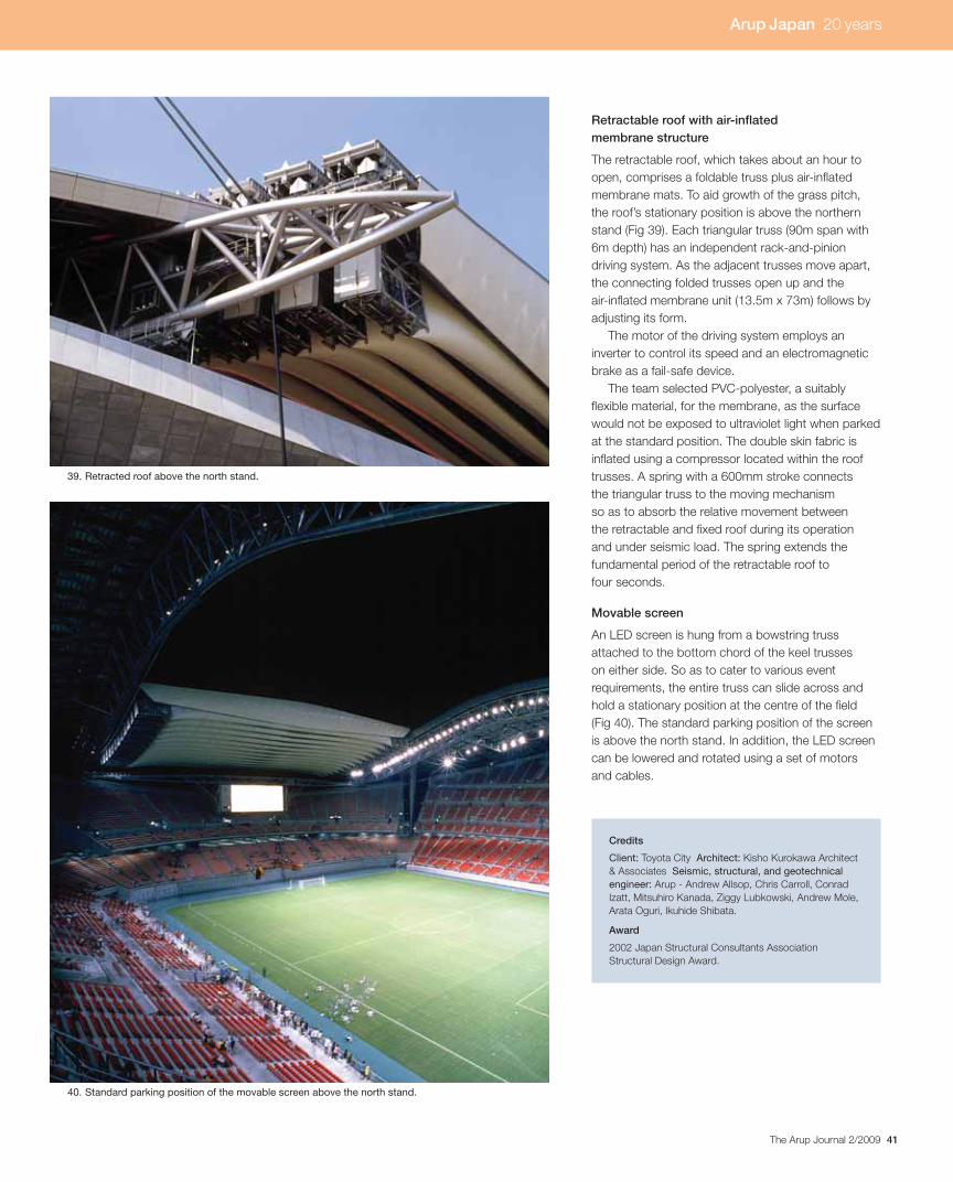
41The Arup Journal 2/2009
Retractable roof with air-inflated membrane structure
The retractable roof, which takes about an hour to
open, comprises a foldable truss plus air-inflated
membrane mats. To aid growth of the grass pitch,
the roof’s stationary position is above the northern
stand (Fig 39). Each triangular truss (90m span with
6m depth) has an independent rack-and-pinion
driving system. As the adjacent trusses move apart,
the connecting folded trusses open up and the
air-inflated membrane unit (13.5m x 73m) follows by
adjusting its form.
The motor of the driving system employs an
inverter to control its speed and an electromagnetic
brake as a fail-safe device.
The team selected PVC-polyester, a suitably
flexible material, for the membrane, as the surface
would not be exposed to ultraviolet light when parked
at the standard position. The double skin fabric is
inflated using a compressor located within the roof
trusses. A spring with a 600mm stroke connects
the triangular truss to the moving mechanism
so as to absorb the relative movement between
the retractable and fixed roof during its operation
and under seismic load. The spring extends the
fundamental period of the retractable roof to
four seconds.
Movable screen
An LED screen is hung from a bowstring truss
attached to the bottom chord of the keel trusses
on either side. So as to cater to various event
requirements, the entire truss can slide across and
hold a stationary position at the centre of the field
(Fig 40). The standard parking position of the screen
is above the north stand. In addition, the LED screen
can be lowered and rotated using a set of motors
and cables.
Credits
Client: Toyota City Architect: Kisho Kurokawa Architect
& Associates Seismic, structural, and geotechnical engineer: Arup - Andrew Allsop, Chris Carroll, Conrad
Izatt, Mitsuhiro Kanada, Ziggy Lubkowski, Andrew Mole,
Arata Oguri, Ikuhide Shibata.
Award
2002 Japan Structural Consultants Association
Structural Design Award.
39. Retracted roof above the north stand.
40. Standard parking position of the movable screen above the north stand.
Arup Japan 20 years
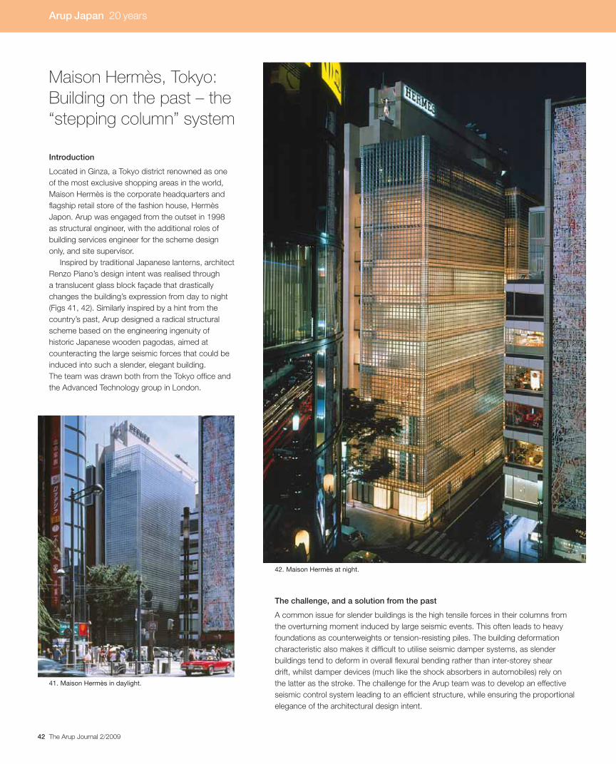
42 The Arup Journal 2/2009
Introduction
Located in Ginza, a Tokyo district renowned as one
of the most exclusive shopping areas in the world,
Maison Hermès is the corporate headquarters and
flagship retail store of the fashion house, Hermès
Japon. Arup was engaged from the outset in 1998
as structural engineer, with the additional roles of
building services engineer for the scheme design
only, and site supervisor.
Inspired by traditional Japanese lanterns, architect
Renzo Piano’s design intent was realised through
a translucent glass block façade that drastically
changes the building’s expression from day to night
(Figs 41, 42). Similarly inspired by a hint from the
country’s past, Arup designed a radical structural
scheme based on the engineering ingenuity of
historic Japanese wooden pagodas, aimed at
counteracting the large seismic forces that could be
induced into such a slender, elegant building.
The team was drawn both from the Tokyo office and
the Advanced Technology group in London.
Maison Hermès, Tokyo: Building on the past – the “stepping column” system
The challenge, and a solution from the past
A common issue for slender buildings is the high tensile forces in their columns from
the overturning moment induced by large seismic events. This often leads to heavy
foundations as counterweights or tension-resisting piles. The building deformation
characteristic also makes it difficult to utilise seismic damper systems, as slender
buildings tend to deform in overall flexural bending rather than inter-storey shear
drift, whilst damper devices (much like the shock absorbers in automobiles) rely on
the latter as the stroke. The challenge for the Arup team was to develop an effective
seismic control system leading to an efficient structure, while ensuring the proportional
elegance of the architectural design intent.
41. Maison Hermès in daylight.
42. Maison Hermès at night.
Arup Japan 20 years

43The Arup Journal 2/2009
Intriguingly, despite onerous earthquake conditions in Japan, it is reported that
out of the 500 or so wooden pagodas, only two have collapsed as the result of an
earthquake in the last 1400 years. What makes it possible for these slender pagodas
to survive earthquakes? The answer is that the joints in the structure are kept loose
to avoid the extreme build-up of forces that can lead to catastrophic failure. For
example, the columns at the lowest storey are not bound to the ground, enabling
them to lift up when the earthquake-induced tension force exceeds the gravity loads.
A vital hint from the intuitive engineering from the past, this “stepping column” proved
the system of choice for this structure (Fig 43).
Application
Maison Hermès is a 12-storey steel-framed building approximately 50m in height,
which resulted in an aspect ratio for the main frame of more than 10:1. Vertical
support is provided by three sets of columns spaced at 3.6m along the short side
facing the street. The rear line of columns is allowed to step up vertically, reducing
the building’s stiffness and thus the impact from an earthquake. In summary, when
experiencing large seismic forces, the structure is designed to flex and pivot around
the centre row of columns, applying compression force to the front row and in turn
slightly lifting up the rear.
To control the impact load and achieve balance in the drift performance of the
system, damping is incorporated in the form of a multi-layered sandwich of steel and
viscoelastic material – a device that Arup specially designed for this scheme (Fig 44).
As the columns lift up, the viscoelastic dampers are stretched (sheared) and so
absorb some of the system’s energy and reduce the building drift.
Impact analysis
As the stepping column system is a half-cycle damper without a steady state, unique
and innovative even by Japan’s seismic engineering standards, the team conducted
rigorous analyses to verify the behaviour. Naturally, the issue of impact of the stepping
column as it hits the ground necessitated in-depth studies.
44. Rendering of stepping column detail (a) and stepping column being craned into place (b).
a) b)
45. LS-DYNA impact analysis model.
46. Stepping column and surrounding frame.
43. Sesmic-resistant technologies from the fifth and 21st centuries: the Japanese pagoda and Maison Hermès.
Discontinuouscolumns- period shift
Flexible joint- added damping
Columns allowed to uplift- period shift
Energy absorption by viscoelastic dampers- added damping
Arup Japan 20 years

44 The Arup Journal 2/2009
The Arup team realised that analysis methods and software developed to simulate car
crash tests could be applied to verify the impact performance. Whilst the time step of
0.01 seconds for the non-linear time history analysis was sufficiently small to capture
the overall behaviour of the structure, to quantify the effect of the impact-induced
“stress wave” the time step and element size needed to be much smaller. This being
the case, LS-DYNA, an explicit code commonly used to perform vehicular crash
worthiness analysis with a time step of 0.000001 sec (a millionth of a second!), was
used for this work.
Through these analyses, the team found that while a heavier mass has larger
momentum leading to a higher overall maximum force, the stress wave is independent
of the mass. As a result, the complex force paths through various elements in the
stepping column were plotted in detail – demonstrating that the impact-induced force
occurred with a offset in time and was a mere 10% of the maximum force that the
columns experience.
Theory to reality
The immense challenges of developing this seismic control system were successfully
overcome as a result of Arup’s seamless global collaboration efforts, expertise gained
by the firm’s work in state-of-the-art analysis techniques, the involvement of Japanese
experts in viscoelastic damper applications… and a key inspiration from the country’s
past. The impressive workmanship of Japanese steel craftsmen also played a vital
role in realising the intricate detailing of the special connection joints.
Throughout, the drive for appropriate innovation and excellence contributed to
delivering this internationally designed, modern, yet elegantly “Japanese” piece of
architecture. Begun on site in December 1999 and completed in May 2001, the
building has successfully withstood the numerous small and moderately-scaled
seismic events that have occurred in Tokyo since.
Credits
Client: Hermès Japon Architect: Renzo Piano Building
Workshop Structural and building services engineer (scheme design only) and site supervisor: Arup – Mitsuhiro Kanada,
Bob Lang, Masato Minami, Andrew Mole, Yoshiyuki Mori,
Paul Sloman General contractors: Takenaka Corporation
Interior design: Rena Dumas Architecture Intérieure
Viscoelastic damping material: Sumitomo 3M.
Awards
2002 Gengo Matsui Award for Structural Design
2003 Building Contractors Award.
47. The elegant interior.
48. Entrance to the store.
Arup Japan 20 years

45The Arup Journal 2/2009
Introduction
NTT DoCoMo, a subsidiary of Japan’s telephone operator NTT (NipponTelegraph and Telephone), is the country’s main mobile phone operator. The DoCoMo tower, for which Arup undertook the structural and seismic engineering design, is a unique cable-guyed telecommunications tower completed in December 2004 on the roof of a large seismically-isolated telecommunications building (Figs 49-51).
Arup Japan led the structural design team in collaboration with the Advanced Technology Group in London and the Detroit, USA, office. ATG London carried out non-linear time history analysis to verify the analysis done in Tokyo, while Detroit undertook 3-D finite element stress analyses of the cast pieces.The site was on reclaimed land, so the structural and foundation design was strongly influenced by the soil conditions. The design criteria for the building required that the structure should remain elastic even for the greatest anticipated earthquake, and to satisfy these criteria, a seismic isolation system and damping devices were installed in the middle storeys. The tower itself has to remain elastic under wind loading, which was estimated from wind tunnel test results to be extremely high, due to the proximity of several tall buildings. Damping devices were installed to satisfy the design criteria for the tower.
NTT DoCoMo tower, Osaka
116.8m
54.25m
145.5m
Total height199.75m
Structural overview of the building
The telecommunications facility is a 12-storey building 54.25m high, 116.8m wide (X-direction), and 43.2m deep (Y-direction). Constructed on a 6.4m grid, its total floor area is 60 993.42m2.
The seismic isolation system was essential to guarantee sufficient safety and to maintain building functions in the event of a disaster like a major earthquake. It comprises 46 lead rubber bearings, 42 rubber bearings, and four cross-linear bearings – 92 isolators in all. The lead rubber bearings and rubber bearings are 1000-1500mm in diameter and 280mm in total thickness of the rubber portion.
The braced and rigid frame uses concrete-filled columns and steel beams, and viscous walls are employed for the damping devices, of which 24 and 22 are arranged in the X- and Y-directions respectively between the third and eighth storeys.
49. Elevation of the NTT DoCoMo tower and building.
50. Aerial view of the NTT DoCoMo building and tower, showing the location overlooking Osaka Bay.
51. The tower and building at night.
Arup Japan 20 years
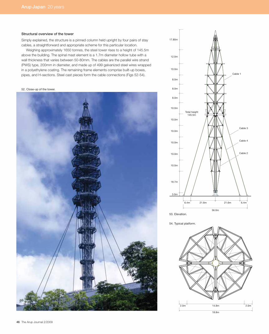
46 The Arup Journal 2/2009
54. Typical platform.
53. Elevation.
Structural overview of the tower
Simply explained, the structure is a pinned column held upright by four pairs of stay
cables, a straightforward and appropriate scheme for this particular location.
Weighing approximately 1650 tonnes, the steel tower rises to a height of 145.5m
above the building. The spinal mast element is a 1.7m diameter hollow tube with a
wall thickness that varies between 50-80mm. The cables are the parallel wire strand
(PWS) type, 200mm in diameter, and made up of 499 galvanized steel wires wrapped
in a polyethylene coating. The remaining frame elements comprise built-up boxes,
pipes, and H-sections. Steel cast pieces form the cable connections (Figs 52-54).
10.0m
10.0m
10.0m
3.0m
8.0m
10.0m
12.0m
17.80m
Cable 1
Cable 3
Cable 4
Cable 2
18.7m
Total height145.5m
10.0m
10.0m
10.0m
8.0m
8.0m
56.0m
6.4m 6.4m21.6m 21.6m
14.8m2.0m 2.0m
18.8m
52. Close-up of the tower.
Arup Japan 20 years
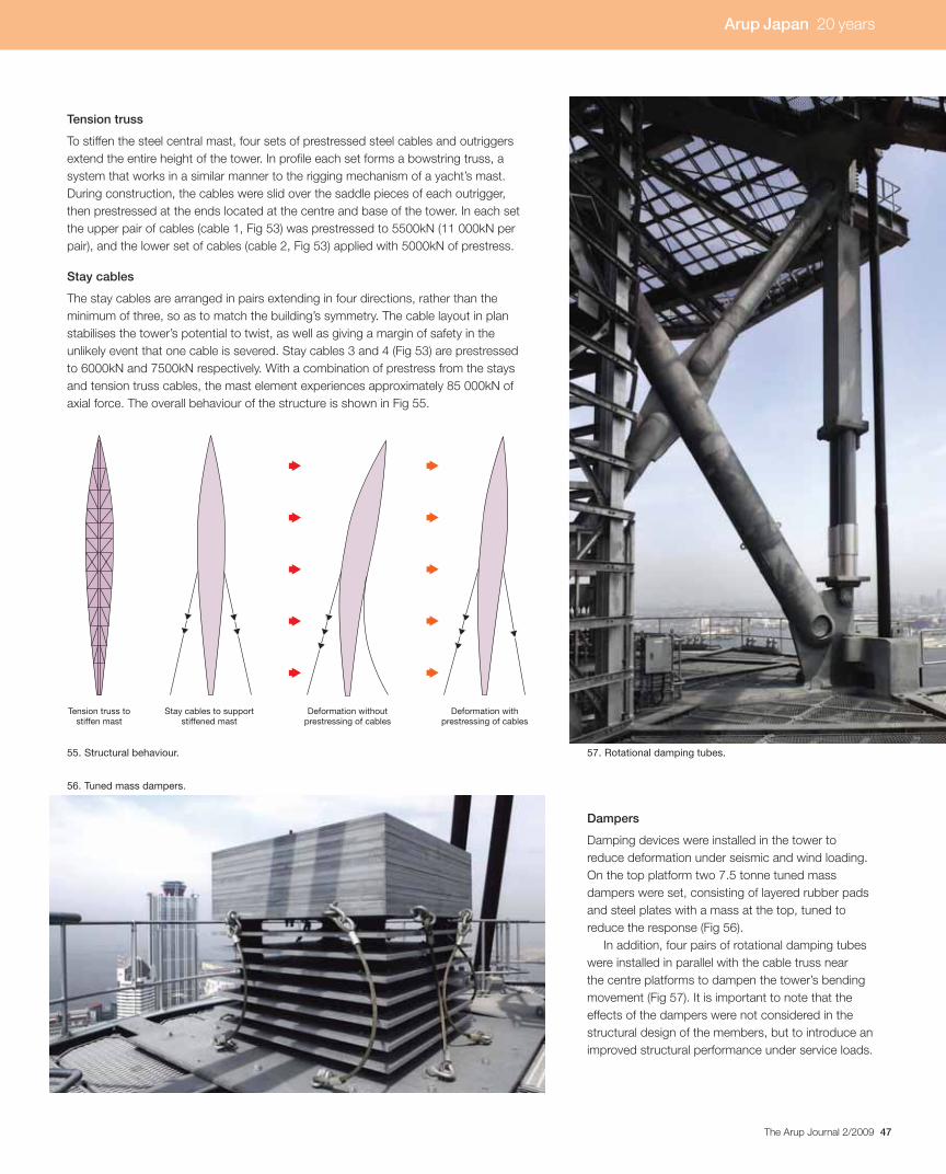
47The Arup Journal 2/2009
55. Structural behaviour.
Tension truss
To stiffen the steel central mast, four sets of prestressed steel cables and outriggers
extend the entire height of the tower. In profile each set forms a bowstring truss, a
system that works in a similar manner to the rigging mechanism of a yacht’s mast.
During construction, the cables were slid over the saddle pieces of each outrigger,
then prestressed at the ends located at the centre and base of the tower. In each set
the upper pair of cables (cable 1, Fig 53) was prestressed to 5500kN (11 000kN per
pair), and the lower set of cables (cable 2, Fig 53) applied with 5000kN of prestress.
Stay cables
The stay cables are arranged in pairs extending in four directions, rather than the
minimum of three, so as to match the building’s symmetry. The cable layout in plan
stabilises the tower’s potential to twist, as well as giving a margin of safety in the
unlikely event that one cable is severed. Stay cables 3 and 4 (Fig 53) are prestressed
to 6000kN and 7500kN respectively. With a combination of prestress from the stays
and tension truss cables, the mast element experiences approximately 85 000kN of
axial force. The overall behaviour of the structure is shown in Fig 55.
Tension truss to stiffen mast
Stay cables to support stiffened mast
Deformation without prestressing of cables
Deformation with prestressing of cables
Dampers
Damping devices were installed in the tower to
reduce deformation under seismic and wind loading.
On the top platform two 7.5 tonne tuned mass
dampers were set, consisting of layered rubber pads
and steel plates with a mass at the top, tuned to
reduce the response (Fig 56).
In addition, four pairs of rotational damping tubes
were installed in parallel with the cable truss near
the centre platforms to dampen the tower’s bending
movement (Fig 57). It is important to note that the
effects of the dampers were not considered in the
structural design of the members, but to introduce an
improved structural performance under service loads.
56. Tuned mass dampers.
57. Rotational damping tubes.
Arup Japan 20 years
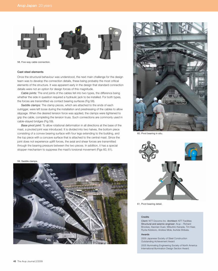
48 The Arup Journal 2/2009
Cast steel elements
Once the structural behaviour was understood, the next main challenge for the design
team was to develop the connection details, these being probably the most critical
elements of the structure. It was apparent early in the design that standard connection
details were not an option for design forces of this magnitude.
Cable joints: The end joints of the cables fell into two types, the difference being
whether the side in question required a hydraulic jack to be installed. For both types,
the forces are transmitted via contact bearing surfaces (Fig 58).
Saddle clamps: The clamp pieces, which are attached to the ends of each
outrigger, were left loose during the installation and prestressing of the cables to allow
slippage. When the desired tension force was applied, the clamps were tightened to
grip the cable, completing the tension truss. Such connections are commonly used in
cable-stayed bridges (Fig 59).
Base pivot joint: To allow rotational deformation in all directions at the base of the
mast, a pivoted joint was introduced. It is divided into two halves, the bottom piece
consisting of a convex bearing surface with four legs extending to the building, and
the top piece with a concave surface that is attached to the central mast. Since the
joint does not experience uplift forces, the axial and shear forces are transmitted
through the bearing pressure between the two pieces. In addition, it has a special
stopper mechanism to suppress the mast’s torsional movement (Figs 60, 61).
Credits
Client: NTT Docomo Inc Architect: NTT Facilities
Structural and seismic engineer: Arup – Richard
Brookes, Xiaonian Duan, Mitsuhiro Kanada, Tim Keer,
Ryota Kidokoro, Andrew Mole, Ikuhide Shibata.
Awards
2005 Japanese Society of Steel Construction
Outstanding Achievement Award
2005 Illuminating Engineering Society of North America
International Illumination Design Section Award.
58. Five-way cable connection.
59. Saddle clamps.
60. Pivot bearing in situ.
61. Pivot bearing detail.
Arup Japan 20 years

49The Arup Journal 2/2009
Introduction
This high-profiled office building, on an 18 165m2 site at Shinagawa in the heart of
Tokyo, is a massive 20-storey near-cube, 100m x 70m on plan and 99.4m in height.
The middle and upper storeys are office space with typical storey-to-storey heights of
4.55m, while the lower floors contain a large conference hall, meeting rooms, cafés,
and restaurants. Two basement floors accommodate a car park and machine rooms.
Designed by Plantec Architects with Arup as structural, seismic, and façade engineer,
this building was completed in 2006.
Base isolation
The adoption of a base isolation system as the chosen method of seismic protection
was driven by two key factors: the architect’s desire for a light transparent façade with
an expressed diagrid, and the client’s requirement for a high degree of seismic safety.
In a base isolation system the structure is decoupled from horizontal movements of
the ground by the use of a layer of bearings that are vertically very stiff but horizontally
very flexible. In the case of Sony City these are multilayered laminates of elastomeric
steel and rubber, made by vulcanisation bonding of the rubber sheets to thin steel
plates (Fig 63). These bearings greatly reduce the structure’s fundamental frequency
so that deformation occurs entirely in the isolation layer. This reduction detunes the
building from the high frequencies that contain large amounts of energy from ground
shaking. In consequence it doesn’t absorb earthquake energy but rather dodges it.
Damping to the system is provided by the high damping elastomeric rubber in the
isolators combined with viscous dampers.
Sony City, Tokyo:A diagrid combined with base isolation
Structural outline
Plantec Architects wanted to express the perimeter
diagrid structure and to use a double skin façade.
The benefits of a diagrid structure are well known,
in particular its high degree of horizontal structural
stiffness, while a double skin façade provides noise
and thermal insulation and allows natural daylighting
and airflow ventilation. However, the presence of
the delicate and expensive diamond-shaped double
skin façade module between the braces of the
diagrid meant that storey drifts needed to be
tightly controlled.
This requirement imposed by the façade seems
like a good match with the naturally high stiffness of
the diagrid. However, in earthquake-prone regions,
the high stiffness of diagrids for buildings shaped like
Sony City attracts very large seismic forces, resulting
in a heavy and uneconomical structure.
An additional factor was that, as a high-profiled
office building, it needed to protect not only human
lives and tangible property but also important
electronic data.
Taking advantage of the stiff nature of the
structural scheme (resulting from the architectural
design intent) and at the same time meeting the
challenging seismic performance requirements,
Arup’s proposed solution was to base isolate the
building. There is a cost premium for using base
Table 1. Design criteria in earthquake of 500-yearreturn period.
Superstructure All structural members in elastic stateStorey drift angle within 1/500
Isolating layer Deformation of isolators less than 250%No tension in isolatorsStrokes of viscous dampers lessthan 550mm
Substructure All structural members in elastic state
62. External view.
63. Close-up of rubber bearings.
Arup Japan 20 years

50 The Arup Journal 2/2009
isolation; typically it adds about 5% to the cost of
the structure, even when the reduction in structural
material is factored in. The additional cost lies mainly
in additional excavation and extra floor structure.
Services and elevators passing through the isolation
layer have to be carefully detailed to permit lateral
movements of up to 500mm. But the benefits for this
project were great. It enabled the the diagrid design
intent to be achieved and furthermore provided
exceptionally high seismic performance.
The isolating layer is between the first and second
basement floors and comprises 200 rubber bearings,
of which 184 are high-damping bearings, and 40
viscous dampers (Fig 64). The bearings were subject
to full-scale tests, in pairs, the first time this has been
done. Each of the columns of the inner frame, which
are subject to large axial forces, is supported by four
rubber bearings. The viscous dampers are located
in the perimeter so that they work effectively against
both translational and twisting motion.
In order to transfer the lateral force from the
superstructure smoothly, its steel columns were
embedded in the isolating layer and steel elements
were cast into the ground floor beams. Within
the superstructure there are concrete filled tubes
(CFT) for the internal columns (Fig 65), while the
substructure is a reinforced concrete construction
with shear walls.
65. CFT internal columns.
66. Aerial view.
64. Viscous damper (a) and (b) rubber bearing.
b)a)
67. Structural system.
Diagonalperimeterframe
Inner rigid frame
Core braces on lower floors
Base isolator
Arup Japan 20 years
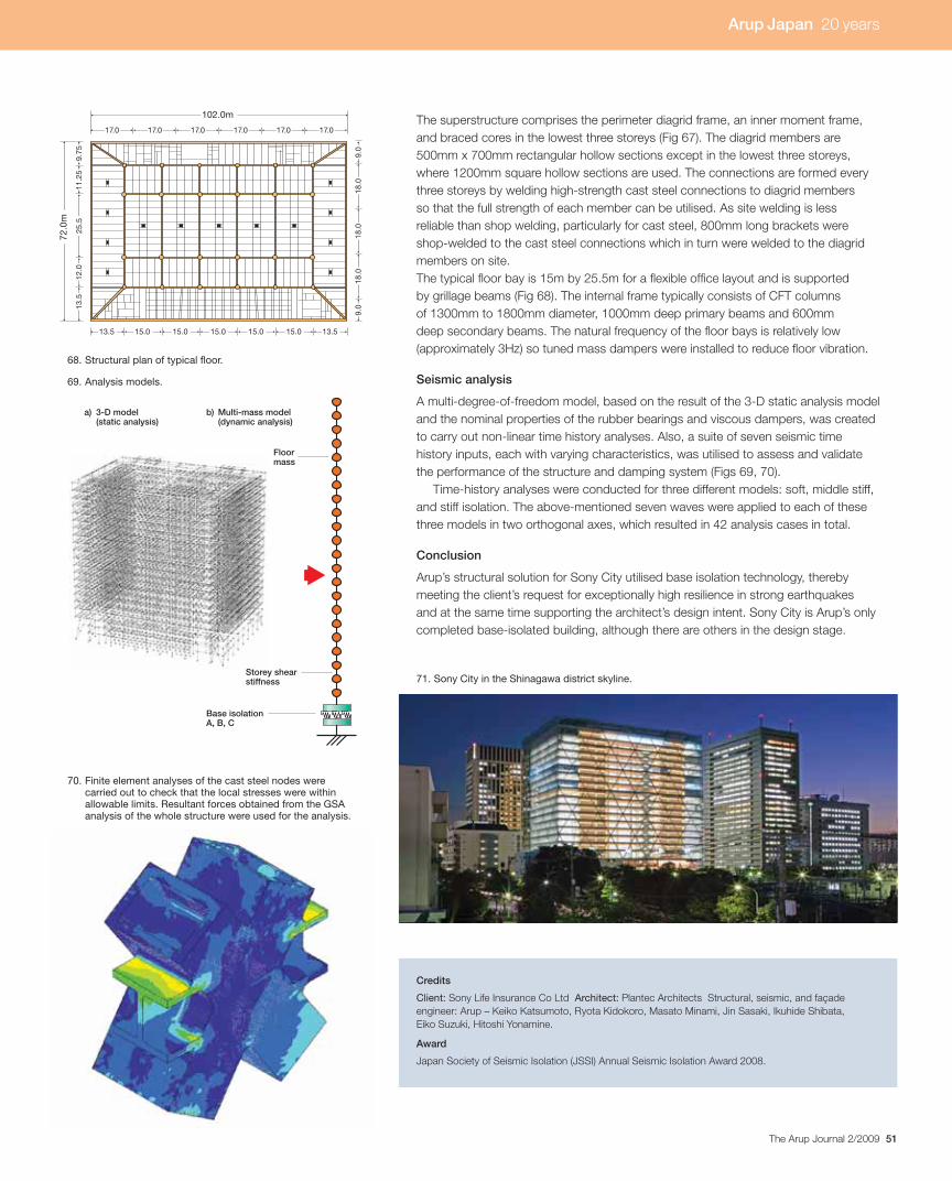
51The Arup Journal 2/2009
Credits
Client: Sony Life Insurance Co Ltd Architect: Plantec Architects Structural, seismic, and façade
engineer: Arup – Keiko Katsumoto, Ryota Kidokoro, Masato Minami, Jin Sasaki, Ikuhide Shibata,
Eiko Suzuki, Hitoshi Yonamine.
Award
Japan Society of Seismic Isolation (JSSI) Annual Seismic Isolation Award 2008.
72.0
m
9.75
11.2
512
.013
.525
.5
9.0
9.0
18.0
18.0
18.0
102.0m
17.0 17.0 17.0 17.0 17.0 17.0
13.5 13.515.0 15.0 15.0 15.0 15.0
68. Structural plan of typical floor.
The superstructure comprises the perimeter diagrid frame, an inner moment frame,
and braced cores in the lowest three storeys (Fig 67). The diagrid members are
500mm x 700mm rectangular hollow sections except in the lowest three storeys,
where 1200mm square hollow sections are used. The connections are formed every
three storeys by welding high-strength cast steel connections to diagrid members
so that the full strength of each member can be utilised. As site welding is less
reliable than shop welding, particularly for cast steel, 800mm long brackets were
shop-welded to the cast steel connections which in turn were welded to the diagrid
members on site.
The typical floor bay is 15m by 25.5m for a flexible office layout and is supported
by grillage beams (Fig 68). The internal frame typically consists of CFT columns
of 1300mm to 1800mm diameter, 1000mm deep primary beams and 600mm
deep secondary beams. The natural frequency of the floor bays is relatively low
(approximately 3Hz) so tuned mass dampers were installed to reduce floor vibration.
Seismic analysis
A multi-degree-of-freedom model, based on the result of the 3-D static analysis model
and the nominal properties of the rubber bearings and viscous dampers, was created
to carry out non-linear time history analyses. Also, a suite of seven seismic time
history inputs, each with varying characteristics, was utilised to assess and validate
the performance of the structure and damping system (Figs 69, 70).
Time-history analyses were conducted for three different models: soft, middle stiff,
and stiff isolation. The above-mentioned seven waves were applied to each of these
three models in two orthogonal axes, which resulted in 42 analysis cases in total.
Conclusion
Arup’s structural solution for Sony City utilised base isolation technology, thereby
meeting the client’s request for exceptionally high resilience in strong earthquakes
and at the same time supporting the architect’s design intent. Sony City is Arup’s only
completed base-isolated building, although there are others in the design stage.
69. Analysis models.
71. Sony City in the Shinagawa district skyline.
70. Finite element analyses of the cast steel nodes were carried out to check that the local stresses were within allowable limits. Resultant forces obtained from the GSA analysis of the whole structure were used for the analysis.
Floormass
Storey shear stiffness
Base isolation A, B, C
a) 3-D model (static analysis)
b) Multi-mass model (dynamic analysis)
Arup Japan 20 years
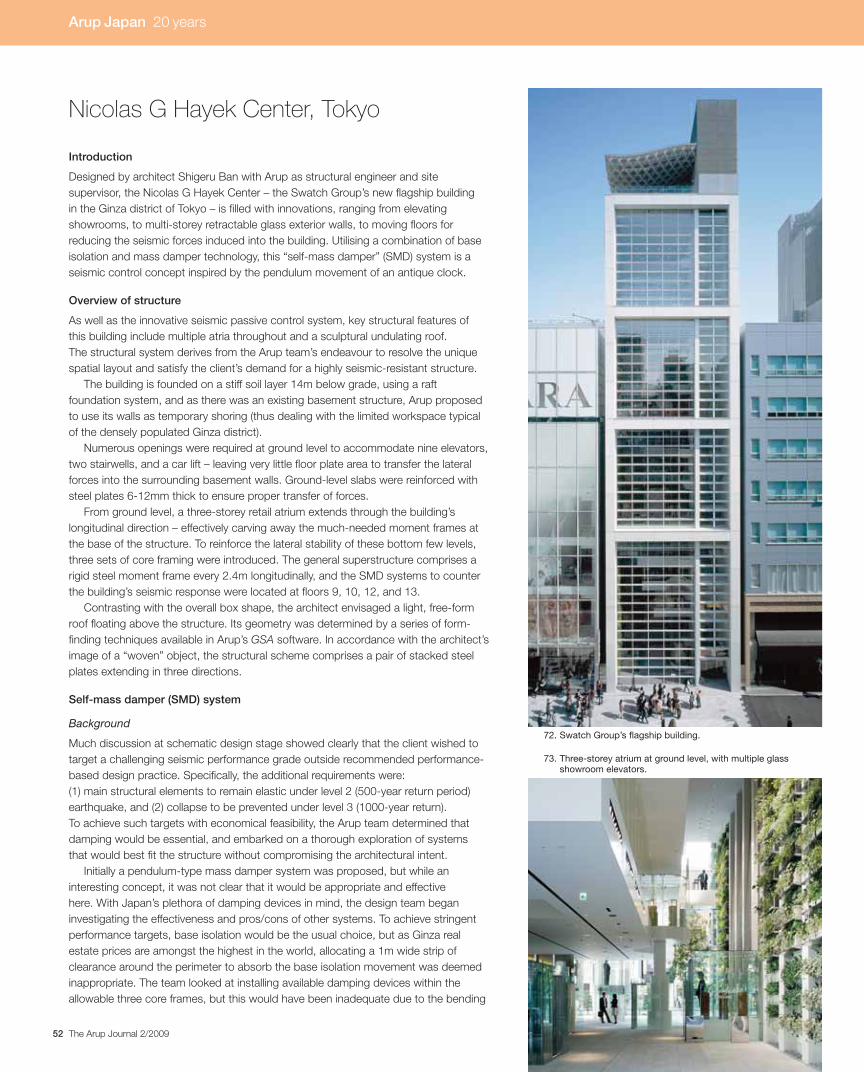
52 The Arup Journal 2/2009
Introduction
Designed by architect Shigeru Ban with Arup as structural engineer and site
supervisor, the Nicolas G Hayek Center – the Swatch Group’s new flagship building
in the Ginza district of Tokyo – is filled with innovations, ranging from elevating
showrooms, to multi-storey retractable glass exterior walls, to moving floors for
reducing the seismic forces induced into the building. Utilising a combination of base
isolation and mass damper technology, this “self-mass damper” (SMD) system is a
seismic control concept inspired by the pendulum movement of an antique clock.
Overview of structure
As well as the innovative seismic passive control system, key structural features of
this building include multiple atria throughout and a sculptural undulating roof.
The structural system derives from the Arup team’s endeavour to resolve the unique
spatial layout and satisfy the client’s demand for a highly seismic-resistant structure.
The building is founded on a stiff soil layer 14m below grade, using a raft
foundation system, and as there was an existing basement structure, Arup proposed
to use its walls as temporary shoring (thus dealing with the limited workspace typical
of the densely populated Ginza district).
Numerous openings were required at ground level to accommodate nine elevators,
two stairwells, and a car lift – leaving very little floor plate area to transfer the lateral
forces into the surrounding basement walls. Ground-level slabs were reinforced with
steel plates 6-12mm thick to ensure proper transfer of forces.
From ground level, a three-storey retail atrium extends through the building’s
longitudinal direction – effectively carving away the much-needed moment frames at
the base of the structure. To reinforce the lateral stability of these bottom few levels,
three sets of core framing were introduced. The general superstructure comprises a
rigid steel moment frame every 2.4m longitudinally, and the SMD systems to counter
the building’s seismic response were located at floors 9, 10, 12, and 13.
Contrasting with the overall box shape, the architect envisaged a light, free-form
roof floating above the structure. Its geometry was determined by a series of form-
finding techniques available in Arup’s GSA software. In accordance with the architect’s
image of a “woven” object, the structural scheme comprises a pair of stacked steel
plates extending in three directions.
Self-mass damper (SMD) system
Background
Much discussion at schematic design stage showed clearly that the client wished to
target a challenging seismic performance grade outside recommended performance-
based design practice. Specifically, the additional requirements were:
(1) main structural elements to remain elastic under level 2 (500-year return period)
earthquake, and (2) collapse to be prevented under level 3 (1000-year return).
To achieve such targets with economical feasibility, the Arup team determined that
damping would be essential, and embarked on a thorough exploration of systems
that would best fit the structure without compromising the architectural intent.
Initially a pendulum-type mass damper system was proposed, but while an
interesting concept, it was not clear that it would be appropriate and effective
here. With Japan’s plethora of damping devices in mind, the design team began
investigating the effectiveness and pros/cons of other systems. To achieve stringent
performance targets, base isolation would be the usual choice, but as Ginza real
estate prices are amongst the highest in the world, allocating a 1m wide strip of
clearance around the perimeter to absorb the base isolation movement was deemed
inappropriate. The team looked at installing available damping devices within the
allowable three core frames, but this would have been inadequate due to the bending
Nicolas G Hayek Center, Tokyo
73. Three-storey atrium at ground level, with multiple glass showroom elevators.
72. Swatch Group’s flagship building.
Arup Japan 20 years

53The Arup Journal 2/2009
Utilise existingbasement walls fortemporary shoring
Multiple flooropenings toaccommodateshowroomelevators
Retail floors hungfrom above to createatrium space
SMD systemslocated atfloors 9, 10, 12, 13
Three-storey“super” moment
frame
Three-storey“super” moment
frame
Raftfoundation
Undulating roof composedof intertwined steel plates
Rigid momentframes placed atevery 2.4m
12.6m
55.9
4m
Sliderbearing
Mainstructure
SMDfloor
600mm
High-dampingrubber bearings
c)a)
b)
d)
Corbel
Corbel
Mainstructure
SMDfloor 600mm
Spring anddamper
Floor platemass
High-dampingrubber bearings
Sliderbearing
55.94m
12.6m
deformation shape of the slender core frames. Though a mass damper would
depend on the mobilised mass quantity and tuning of the system, preliminary studies
indicated that such a system could be extremely effective for this slender building.
Evolution of the mass damper scheme
Unlike mass damping to control low-energy wind responses, to deal with large
seismic forces by this method requires a great deal of mass to be effective.
Characteristically, practical effectiveness begins at around 5% mobilisation of
the building mass. As the mobilised mass increases, the system can be more
appropriately categorised as a mid-level isolation system, and finally when the
mobilised mass is 100% of the building mass, it becomes a base-isolated structure.
Typically, mass dampers are integrated into buildings by augmenting unutilised
mass into the structure, but if, say, 10% of the total building mass is added at the top
for seismic control, it is detrimental in terms of overall impact on the building. This
is why mass dampers are not used to control seismic response. The design team
therefore looked at how to mobilise existing, necessary mass as a mass damper.
The front elevation (Fig 72) clearly shows the building’s groups of three-storey atria
(sky gardens). With the upper sky garden blocks and the resulting three-level “super-
frame” impression in mind (Fig 75), the first proposal was to hang two of the floors,
released from the building to create a “swinging pendulum” utilising the floor plate’s
self-mass. However, due to issues such as the hanger elements intruding into the
office space and vertical displacements of the floors due to the rocking movement,
alternatives were explored.
74. Fifth floor atrium with retracted glass exterior wall.
75. Key structural features, including three-storey“super-frames”.
76. The “self-mass damper” system: (a) concept (b) floor-plan; (c) section showing rubber bearingand (d) slider bearing.
Arup Japan 20 years
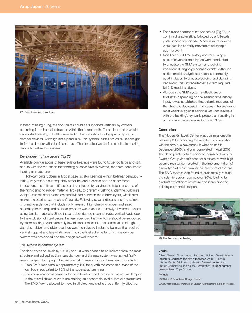
54 The Arup Journal 2/2009
confirm characteristics, followed by a full-scale
push-release test on site. Measurement devices
were installed to verify movement following a
seismic event.
suite of seven seismic inputs were conducted
to simulate the SMD system and building
behaviour during large seismic events. Although
a stick model analysis approach is commonly
used in Japan to simulate building and damping
behaviour, this unprecedented system required
full 3-D model analysis.
fluctuates depending on the seismic time history
input, it was established that seismic response of
the structure decreased in all cases. The system is
most effective against earthquakes that resonate
with the building’s dynamic properties, resulting in
a maximum base shear reduction of 37%.
Conclusion
The Nicolas G Hayek Center was commissioned in
February 2005 following the architect’s competition
win the previous November. It went on site in
December 2005, and was completed in April 2007.
The daring architectural concept, combined with the
Swatch Group Japan’s wish for a structure with high
seismic resistance, resulted in the implementation of
a new type of mass damper passive control system.
The SMD system was found to successfully reduce
the seismic design load by over 30%, leading to
a robust yet efficient structure and increasing the
building’s potential lifespan.
Instead of being hung, the floor plates could be supported vertically by corbels
extending from the main structure within the beam depth. These floor plates would
be isolated laterally, but still connected to the main structure by special spring and
damper devices. Although not a pendulum, this system utilises structural self-weight
to form a damper with significant mass. The next step was to find a suitable bearing
device to realise this system.
Development of the device (Fig 76)
Available configurations of base isolator bearings were found to be too large and stiff,
and so with the realisation that nothing suitable already existed, the team consulted a
leading manufacturer.
High-damping rubbers in typical base isolator bearings exhibit bi-linear behaviour –
initially very stiff but subsequently softer beyond a certain applied shear force.
In addition, this bi-linear stiffness can be adjusted by varying the height and area of
the high-damping rubber material. Typically, to prevent crushing under the building’s
weight, multiple steel plates are sandwiched between the rubber layers, which also
makes the bearing extremely stiff laterally. Following several discussions, the solution
of creating a device that includes only layers of high-damping rubber and sized
according to the required bi-linear property was reached – a newly-developed device
using familiar materials. Since these rubber dampers cannot resist vertical loads due
to the exclusion of steel plates, the team decided that the floors should be supported
by slider bearings with extremely low friction coefficient. This combination of high-
damping rubber and slider bearings was then placed in plan to balance the required
vertical support and lateral stiffness. Thus the final scheme for this mass damper
system was envisioned and the design moved forward.
The self-mass damper system
The floor plates on levels 9, 10, 12, and 13 were chosen to be isolated from the main
structure and utilised as the mass damper, and the new system was named “self-
mass damper” to highlight the use of existing mass. Its key characteristics include:
four floors equivalent to 10% of the superstructure mass.
to the overall structure while maintaining an acceptable level of lateral deformation.
The SMD floor is allowed to move in all directions and is thus uniformly effective.
Credits
Client: Swatch Group Japan Architect: Shigeru Ban Architects
Structural engineer and site supervisor: Arup – Shigeru
Hikone, Ryota Kidokoro, Jin Sasaki General contractor:Suruga Corporation and Kajima Corporation Rubber damper manufacturer: Toyo Rubber.
Awards
2008 JSCA Structural Design Award
2009 Architectural Institute of Japan Architectural Design Award.
78. Rubber damper testing.
77. Free-form roof structure.
Arup Japan 20 years

55The Arup Journal 2/2009
Introduction
Mode Gakuen is a vocational school for students in
the fields of fashion and interior and graphic design,
with bases in Tokyo, Osaka, Nagoya, and Paris.
In 2004 Mode Gakuen instituted an architectural
competition for its new Tokyo location, and this was
won by Tange Associates. Located in Nishi-Shinjuku
in the heart of Tokyo, this 203.65m-high, 50-storey
skyscraper was commissioned in February 2005 and
completed in October 2008. It is the second-tallest
educational building in the world and the 17th-tallest
building in Tokyo.
MODE GAKUENCocoon Tower
The tower’s curved outline and distinctive cocoon shape (Figs 79, 80) are intended
by the architect to symbolise a nurturing of the students that it accommodates,
and form a boldly different presence amid a dense cluster of conventionally box-
like skyscrapers. The building actually contains three educational bodies catering
for around 10 000 students. As well as the Tokyo Mode Gakuen fashion school, it
also accommodates HAL Tokyo and Shuto Iko, which are respectively information
technology and medical schools.PIT
Annex
Basement parkingand retail
Access and facilities
Classrooms
Student salons
19.6m
29.7m
203.65m
80. External view.
79. Architectural section.
Arup Japan 20 years

56 The Arup Journal 2/2009
The main structure comprises three elliptical diagrid frames and an inner core frame
(Fig 82). Because the three diagrid frames are connected rigidly with each other at
the base and the top only, the building has relatively large shear deformations in
the middle storeys due to the bending of each diagrid frame. The structure can be
viewed as a portal frame with large rotations in the middle and smaller rotations at
the top and bottom. The inter-storey displacement of the perimeter frame is largely
through bending, while that of the inner core is by shear. Viscous dampers are utilised
to exploit the shear deformation of the inner core and to dissipate the associated
seismic energy. On each floor from the 15th to the 39th, the inner core has six viscous
dampers, which reduce the seismic force that needs to be resisted by the structure.
Structural outline
Both superstructures are of steel with concrete-filled tubular columns in the inner
core. The basement is a composite construction of steel and reinforced concrete with
concrete shear walls, while the foundations combine a 3.8m thick raft slab and cast
in situ concrete piles. The pile positions could not coincide with the column positions
due to the complexity of the column arrangement, so the raft above the piles was
used to transfer the vertical forces from the columns to the piles.
The typical tower floor plan is circular with the three
rectangular classroom plans imposed on top (Fig 81).
Each classroom is 24m wide. The depths of the
classrooms vary as the perimeter surface draws an
elliptical curve vertically. Spaces between the
classrooms are used as small atria where students
can refresh themselves between classes.
Next to the tower on the same site is a 30m high
elliptical annex, containing two large lecture theatres
and some retail outlets, including a bookshop.
Both the high-rise building and annex share the same
four-storey basement structure which is used for car
parking and retail space.
Access and facilitiesClassrooms Student salons
83. Internal view of classroom showing diagrid frames.
81. Typical floor plan.
82. Structural system.
Arup Japan 20 years

57The Arup Journal 2/2009
The diagrid frames at the perimeter are 24m wide with intersections every 4m on each
floor level, curving in a vertical ellipse and giving to the structure a wide stance so
that it can efficiently transfer lateral force and overturning moment from earthquake
or wind to the basement. Storey heights are such that the distance on the elliptical
line is uniformly 3.7m, allowing the diagrid members to intersect at the same angle on
each floor. This shows the external patterns smoothly, and significantly simplified the
fabrication of steel and exterior cladding units. Diagrid members are mainly I-sections
400mm wide and 400mm deep – relatively small for such a slender, high-rise building
and helping to maximise the internal space.
The floor beams of classrooms support the floor loads and connect the diagrid
frames and the inner core horizontally, preventing out-of-plane buckling of the diagrid
frames. Most of the classrooms are architecturally designed to expose floor beams
and service ducts in the ceiling (Fig 83) while other areas are finished by ceiling
panels. Parallel floor beams are rigidly connected to the intersection of the diagrid
frames and cranked at the beam above the partition between classroom and corridor
towards the columns of the inner core. The floor beams are rigidly connected at
both ends. As a result, the exposed beams in the classrooms look well-ordered.
Furthermore the diagrid frames are robustly stiffened against out-of-plane buckling.
At intermediate levels there are three-storey atriums for the students to refresh
themselves. Their external glazing is three storeys high and the maximum width is
nearly 20m. Double-arched vierendeel truss beams at each floor level carry the weight
of glazing panels and resist wind pressure. The vierendeel beams are hung from the
beams above so that no structural member obstructs the view on any storey
(Figs 85-86).
Connection design is one of the challenges of a diagrid structure, because many
members (seven in this case) from various angles are concentrated at one point.
There were numerous meetings between the engineers and fabricators to find a
solution that was reasonable to fabricate and structurally robust. In the adopted
solution the intersection node is fabricated from several rolled plates (Fig 88) and
butt-welded with the diagrid and floor members on site.
Viscous damper
87. Typical floor section showing location of viscous dampers on vierendeel beam.
88. Fabricating the intersection node.
85. Three-storey atrium.
86. Typical floor structure showing location ofvierendeel beams.
84. South entrance to tower (left) and annex (right).
Arup Japan 20 years
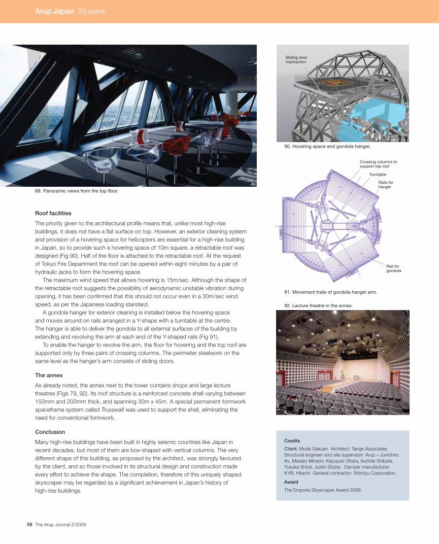
58 The Arup Journal 2/2009
Roof facilities
The priority given to the architectural profile means that, unlike most high-rise
buildings, it does not have a flat surface on top. However, an exterior cleaning system
and provision of a hovering space for helicopters are essential for a high-rise building
in Japan, so to provide such a hovering space of 10m square, a retractable roof was
designed (Fig 90). Half of the floor is attached to the retractable roof. At the request
of Tokyo Fire Department the roof can be opened within eight minutes by a pair of
hydraulic jacks to form the hovering space.
The maximum wind speed that allows hovering is 15m/sec. Although the shape of
the retractable roof suggests the possibility of aerodynamic unstable vibration during
opening, it has been confirmed that this should not occur even in a 30m/sec wind
speed, as per the Japanese loading standard.
A gondola hanger for exterior cleaning is installed below the hovering space
and moves around on rails arranged in a Y-shape with a turntable at the centre.
The hanger is able to deliver the gondola to all external surfaces of the building by
extending and revolving the arm at each end of the Y-shaped rails (Fig 91).
To enable the hanger to revolve the arm, the floor for hovering and the top roof are
supported only by three pairs of crossing columns. The perimeter steelwork on the
same level as the hanger’s arm consists of sliding doors.
The annex
As already noted, the annex next to the tower contains shops and large lecture
theatres (Figs 79, 92). Its roof structure is a reinforced concrete shell varying between
150mm and 200mm thick, and spanning 30m x 45m. A special permanent formwork
spaceframe system called Trusswall was used to support the shell, eliminating the
need for conventional formwork.
Conclusion
Many high-rise buildings have been built in highly seismic countries like Japan in
recent decades, but most of them are box-shaped with vertical columns. The very
different shape of this building, as proposed by the architect, was strongly favoured
by the client, and so those involved in its structural design and construction made
every effort to achieve the shape. The completion, therefore of this uniquely shaped
skyscraper may be regarded as a significant achievement in Japan’s history of
high-rise buildings.
Credits
Client: Mode Gakuen Architect: Tange Associates
Structural engineer and site supervisor: Arup – Junichiro
Ito, Masato Minami, Kazuyuki Ohara, Ikuhide Shibata,
Yusuke Shirai, Justin Stolze Damper manufacturer:
KYB, Hitachi General contractor: Shimizu Corporation.
Award
The Emporis Skyscraper Award 2008.
89. Panoramic views from the top floor.
90. Hovering space and gondola hanger.
92. Lecture theatre in the annex.
Crossing columns tosupport top roof
Rails forhanger
Turntable
Sliding doormechanism
91. Movement trails of gondola hanger arm.
Rail forgondola
Arup Japan 20 years
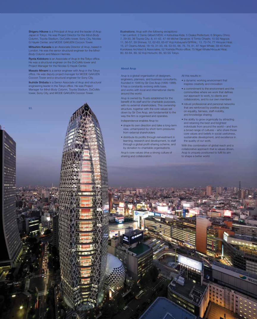
59The Arup Journal 2/2009
Arup is a global organisation of designers,
engineers, planners, and business consultants,
founded in 1946 by Sir Ove Arup (1895-1988).
It has a constantly evolving skills base,
and works with local and international clients
around the world.
Arup is owned by Trusts established for the
benefi t of its staff and for charitable purposes,
with no external shareholders. This ownership
structure, together with the core values set
down by Sir Ove Arup, are fundamental to the
way the fi rm is organised and operates.
Independence enables Arup to:
view, unhampered by short-term pressures
from external shareholders
learning, research and development, to staff
through a global profi t-sharing scheme, and
by donation to charitable organisations.
Arup’s core values drive a strong culture of
sharing and collaboration.
All this results in:
inspires creativity and innovation
communities where we work that defi nes
our approach to work, to clients and
collaborators, and to our own members
that are reinforced by positive policies
on equality, fairness, staff mobility,
and knowledge sharing
and retaining the best and brightest
individuals from around the world – and from
a broad range of cultures – who share those
core values and beliefs in social usefulness,
sustainable development, and excellence in
the quality of our work.
With this combination of global reach and a
collaborative approach that is values-driven,
Arup is uniquely positioned to fulfi l its aim
to shape a better world.
Illustrations: Arup with the following exceptions:1 Ian Lambot; 2 Denis Gilbert/VIEW; 4 Katsuhisa Kida; 5 Osaka Prefecture; 6 Shigeru Ohno;
7, 29-30, 36 Toyota City; 8, 41-42, 47-48 Michel Denance; 9 Tomio Ohashi; 10 SS Nagoya;
11, 56-57, 59 Shinwa; 12, 62-63, 65-67 Koji Kobayashi/SPIRAL; 13, 72-74, 77 Hiroyuki Hirai;
15, 27 Osamu Murai; 18-19, 31-33, 49, 53-55, 68, 76, 79, 81, 87 Nigel Whale; 39-40 Kisho
Kurokawa Architect & Associates; 52 Yoshida Photo-offi ce; 75 Nigel Whale/Hiroyuki Hirai;
80, 83-84, 89, 92 Koji Horiuchi; 85, 93 SS Tokyo.
93.
About Arup
Shigeru Hikone is a Principal of Arup and the leader of Arup
Japan in Tokyo. He was Project Director for the Mind-BodyColumn, Toyota Stadium, DoCoMo tower, Sony City, Nicolas
G Hayek Center, and MODE GAKUEN Cocoon Tower.
Mitsuhiro Kanada is an Associate Director of Arup, based in
London. He was the senior structural engineer for the Mind-Body Column and Maison Hermès.
Ryota Kidokoro is an Associate of Arup in the Tokyo offi ce.
He was a structural engineer on the DoCoMo tower and
Project Manager for the Nicolas G Hayek Center.
Masato Minami is a senior engineer with Arup in the Tokyo
offi ce. He was deputy project manager for MODE GAKUEN
Cocoon Tower and a structural engineer for Sony City.
Ikuhide Shibata is a Senior Associate of Arup and structural
engineering leader in the Tokyo offi ce. He was Project
Manager for Mind-Body Column, Toyota Stadium, DoCoMo
tower, Sony City, and MODE GAKUEN Cocoon Tower.

The Arup Journal Vol.44 No.2 (2/2009)
Editor: David J Brown Designer: Nigel Whale
Editorial: Tel: +1 617 349 9291
e-mail: [email protected]
Published by Corporate Communications Group,
Arup, 13 Fitzroy Street, London W1T 4BQ, UK.
Tel: +44 (0)20 7636 1531 Fax: +44 (0)20 7580 3924
All articles ©Arup 2009
www.arup.com
Illustrations: 1. Pivot bearing for NTT DoCoMo tower, Osaka: Shinwa; 2. Retractable roof at Toyota Stadium,
Toyota City, Aichi: Toyota City; 3. Maison Hermès, Tokyo: Michel Denance; 4. Sony City: Koji Kobayashi/SPIRA;
5. Mind-Body Column, Osaka: Arup; 6. Roden Street footbridge, Westlink/M1, Belfast: Andrew Hazard Photography
& Design; 7. Sir Ove Arup on Kingsgate footbridge, Durham, England, during construction, 1963: Arup; 8. MODE
GAKUEN Cocoon Tower: SS Tokyo; 9. The trumpet: one of the most ancient of musical instruments and a symbol of
freedom and diversity: iStockphoto/Karla Caspari; 10. Free-form roof structure for the Nicolas G Hayek Center,
Tokyo: Hiroyuki Hirai.
Front cover: MODE GAKUEN Cocoon Tower: SS Tokyo.
Inside front cover: Water-colour by Roger Rigby of Sir Ove Arup on Kingsgate footbridge, originally painted for the
Ove Arup 90th birthday edition of The Arup Journal, spring 1985.
Special thanks to Dara McDonnell, Keiko Katsumoto, and Ryota Kidokoro for co-ordinating the Arup Japan 20th
anniversary feature.
Printed in England by Beacon Press using its ®environmental print technology. The printing inks are made
from vegetable-based oils and 95% of cleaning solvents are recycled for further use. All electricity was generated from
renewable sources and on average 94% of any waste associated with this product will be recycled. Beacon Press is
a carbon neutral company, and is registered to environmental standards ISO14001 and EMAS.
1. 2. 3
4 5
7 8 9
6
10
Top Related