


Languages
Pages
Legal

Thank you for purchasing a Pacific Floorcare product. Carefully inspect all components for freight damage. If such damage is discovered, file a “CONCEALED DAMAGE REPORT” immediately with the delivering
carrier.
Read this manual carefully and keep it near the machine, protected from liquids and other damaging substances. Failure to follow the instructions may result in injury or damage to equipment and property.
The contents of this manual are based on the latest product information available at the time of publication. Pacific Floorcare reserves the right to make changes or improvements without being obliged to apply changes
to the machines previously sold.
New manuals can be downloaded from: www.pacificfloorcare.com/manuals
S-24 / S-28 / S-32S-24 / S-28 / S-3222 GALLON MID-SIZE AUTOSCRUBBER22 GALLON MID-SIZE AUTOSCRUBBER
PARTS & OPERATING MANUALPARTS & OPERATING MANUAL

22 GALLON AUTOSCRUBBER SPECIFICATIONSFeatures Specifications
Model: S-24 (Disk) S-28 (Orbital)
Solution Delivery SystemSolution capacity: 22 gal / 83 l 22 gal / 83 l
Solution control: (Standard) 0-.55 gpm / 0-2.1 lpm, Variable knob adjustment 0-.55 gpm / 0-2.1 lpm, Variable knob adjustment
Solution control: (w/ Chemical Injection)
Low, Med & High flow settings (.10, .25 & .45 gpm / .38, .95 & 1.7 lpm) Speed Sensitive Flow or Constant Output Flow Control
Low, Med & High flow settings (.10, .25 & .45 gpm / .38, .95 & 1.7 lpm) Speed Sensitive Flow or Constant Output Flow Control
Scrubbing SystemCleaning path: 24 in / 610 mm 28 in / 711 mm
Pad/brush size: (2) 12 in / 305 mm (1) 28 x 14 in / 711 x 356 mm
Productivity (per hour)-Theoretical max: 26,400 ft 30,800 ft
Productivity (per hour)-Average coverage rate:* 19,525 ft 22,425 ft
Brush Drive SystemBrush motor horsepower (each): (1) 1 hp / 750 W (1) 1 hp / 750 W
Brush rpm: 360 rpm 2,200 rpm
Brush/pad pressure: 50, 100 & 140 lb / 23, 45 & 64 kg 70, 110 & 160 lb / 32, 50 & 73 kg
Brush/pad attachment/removal: Automatic on/off Manual
Recovery SystemRecovery tank accessibility: Full clean out access Full clean out access
Recovery tank capacity: 25 gal / 95 l (3 gal / 11.4 l demisting chamber) 25 gal / 95 l (3 gal / 11.4 l demisting chamber)
Vacuum motor: .7 hp / 522 W, 3-stage .7 hp / 522 W, 3-stage
Vac motor cfm / cmm: 71 cfm / 2.0 cmm 71 cfm / 2.0 cmm
Vac motor water-lift: 71 in / 180 cm 71 in / 180 cm
Standard / Narrow Aisle Squeegee width: 35 / 30 in (89 / 76 cm) 40 / 35 in (102 / 89 cm)
Drive SystemDrive Type: Transaxle Drive Transaxle Drive
Motor horsepower: .5 hp / 373 W .5 hp / 373 W
Battery SystemSystem voltage: 24 V 24 V
Battery amp hour rating: (4) 6V: 260 AH (wet) / 250 AH (MF) (4) 6V: 260 AH (wet) / 250 AH (MF)
Battery run time: Up to 5.5 hours Up to 5.5 hours
Charger description: On-board (standard) Off-board (optional)
On-board (standard) Off-board (optional)
Machine specificationsProduct length: 54 in / 137 cm 52 in / 132 cm
Product width (without squeegee): 26 in / 66 cm 28 in / 71 cm
Product height: 44 in / 112 cm 44 in / 112 cm
Product weight (with batteries): 650 lb / 295 kg 665 lb / 302 kg
Sound level (operator’s ear): 65 dBA 63 dBA
Construction: Rotationally molded polyethylene tanks, powder coated steel frame
Rotationally molded polyethylene tanks, powder coated steel frame
*Productivity calculations utilize key factors from ISSA 540 cleaning times handbook
Note: Specifications subject to change without notice

22 GALLON AUTOSCRUBBER SPECIFICATIONSFeatures Specifications
Model: S-28 (Disk) S-32 (Disk)
Solution Delivery SystemSolution capacity: 22 gal / 83 l 22 gal / 83 l
Solution control: (Standard) 0-.55 gpm / 0-2.1 lpm, Variable knob adjustment 0-.55 gpm / 0-2.1 lpm, Variable knob adjustment
Solution control: (w/ Chemical Injection)
Low, Med & High flow settings (.10, .25 & .45 gpm / .38, .95 & 1.7 lpm) Speed Sensitive Flow or Constant Output Flow Control
Low, Med & High flow settings (.10, .25 & .45 gpm / .38, .95 & 1.7 lpm) Speed Sensitive Flow or Constant Output Flow Control
Scrubbing SystemCleaning path: 28 in / 711 mm 32 in / 813 mm
Pad/brush size: (2) 14 in / 356 mm Disks (2) 16 in / 406 mm Disks
Productivity (per hour)-Theoretical max: 30,800 ft 35,200 ft
Productivity (per hour)-Average coverage rate:* 22,425 ft 25,125 ft
Brush Drive SystemBrush motor horsepower (each): (2) 1 hp / 750 W (2) 1 hp / 750 W
Brush rpm: 300 rpm 300 rpm
Brush/pad pressure: 70, 110 & 150 lb / 32, 50 & 68 kg 70, 110 & 150 lb / 32, 50 & 68 kg
Brush/pad attachment/removal: Automatic on/off Automatic on/off
Recovery SystemRecovery tank accessibility: Full clean out access Full clean out access
Recovery tank capacity: 25 gal / 95 l (3 gal / 11.4 l demisting chamber) 25 gal / 95 l (3 gal / 11.4 l demisting chamber)
Vacuum motor: .7 hp / 522 W, 3-stage .7 hp / 522 W, 3-stage
Vac motor cfm / cmm: 71 cfm / 2.0 cmm 71 cfm / 2.0 cmm
Vac motor water-lift: 71 in / 180 cm 71 in / 180 cm
Standard / Narrow Aisle Squeegee width: 40 / 35 in (102 / 89 cm) 44.5 / 40 in (113 / 102 cm)
Drive SystemDrive Type: Transaxle Drive Transaxle Drive
Motor horsepower: .5 hp / 373 W .5 hp / 373 W
Battery SystemSystem voltage: 24 V 24 V
Battery amp hour rating: (4) 6V: 260 AH (wet) / 250 AH (MF) (4) 6V: 260 AH (wet) / 250 AH (MF)
Battery run time: Up to 4.5 hours Up to 4.0 hours
Charger description: On-board (standard) Off-board (optional)
On-board (standard) Off-board (optional)
Machine specificationsProduct length: 56 in / 142 cm 58 in / 147 cm
Product width (without squeegee): 30 in / 76 cm 34 in / 86 cm
Product height: 44 in / 112 cm 44 in / 112 cm
Product weight (with batteries): 660 lb / 299 kg 665 lb / 302 kg
Sound level (operator’s ear): 65 dBA 65 dBA
Construction: Rotationally molded polyethylene tanks, powder coated steel frame
Rotationally molded polyethylene tanks, powder coated steel frame
*Productivity calculations utilize key factors from ISSA 540 cleaning times handbook
Note: Specifications subject to change without notice
TABLE OF CONTENTSTABLE OF CONTENTSSAFETY INFORMATION ���������������������������������������������������������������������������������������������������������������������������������������������������1UNPACKING THE MACHINE �������������������������������������������������������������������������������������������������������������������������������������������2TRANSPORTING THE MACHINE �����������������������������������������������������������������������������������������������������������������������������������3BATTERIES ���������������������������������������������������������������������������������������������������������������������������������������������������������������������������4
SELECTION ..................................................................................................................................................................4INSTALLATION ...........................................................................................................................................................4SERVICING LEAD ACID BATTERIES (NON-HYDROLINK® MODELS) ..............................................................5SERVICING LEAD ACID BATTERIES WITH HYDROLINK® ..............................................................................6WATERING SYSTEM ..................................................................................................................................................6BATTERYSHIELD® AUTOMATED WET BATTERY PROTECTION SYSTEM......................................................7
CHARGING ���������������������������������������������������������������������������������������������������������������������������������������������������������������������������9ON-BOARD CHARGER ..............................................................................................................................................9OFF-BOARD CHARGER ........................................................................................................................................... 11
PRE-USE SETUP �����������������������������������������������������������������������������������������������������������������������������������������������������������������12ORBITAL PADS & CHEMICAL-FREE FINISH REMOVAL (CFR) ........................................................................16DISK MACHINE PAD DRIVERS & BRUSHES .......................................................................................................17SQUEEGEE SYSTEM ................................................................................................................................................19
RECOMMENDED MAINTENANCE �������������������������������������������������������������������������������������������������������������������������������22RECOMMENDED SERVICE PARTS ������������������������������������������������������������������������������������������������������������������������������23TROUBLESHOOTING GUIDE ����������������������������������������������������������������������������������������������������������������������������������������26PARTS DIAGRAMS ������������������������������������������������������������������������������������������������������������������������������������������������������������28
BATTERIES, BATTERYSHIELD® & HYDROLINK® .............................................................................................28OPTIONAL ONBOARD CHARGER .........................................................................................................................29CONTROLS .................................................................................................................................................................30ELECTRONICS ...........................................................................................................................................................37FRAME ASSEMBLY ..................................................................................................................................................41HEAD LIFT ASSEMBLY ............................................................................................................................................42SOLUTION TANK ......................................................................................................................................................43RECOVERY TANK AND VACUUM .........................................................................................................................44OPTIONAL CHEMICAL INJECTION .......................................................................................................................4635” SQUEEGEE ASSEMBLY .....................................................................................................................................4740” SQUEEGEE ASSEMBLY .....................................................................................................................................4845” SQUEEGEE ASSEMBLY .....................................................................................................................................49SQUEEGEE LINK.......................................................................................................................................................50SCRUB HEADS ..........................................................................................................................................................52
WIRING DIAGRAMS ��������������������������������������������������������������������������������������������������������������������������������������������������������64S-24 WIRING DIAGRAM ..........................................................................................................................................64S-28 (DISK) & S-32 WIRING DIAGRAM .................................................................................................................66S-28 ORBITAL WIRING DIAGRAM ........................................................................................................................68BATTERYSHIELD® (OPTIONAL) WIRING DIAGRAM ........................................................................................70OPTIONAL CHEMICAL INJECTION WIRING DIAGRAM ...................................................................................71
WARNING: This product can expose you to chemicals including lead and lead compounds which are known to the State of California to cause cancer and birth defects or other reproductive harm. For more information go to www.P65Warnings.ca.gov.WARNING: This machine is not equipped with explosion proof motors. Never use near flammable or reactive materials, liquids, vapors or combustible dusts. Electric motors spark internally during operation and could cause a flash fire or explosion.WARNING: Batteries emit hydrogen and oxygen gas. - Keep sparks and open flame away. Do not smoke near the machine - Charge batteries in a well-ventilated area with the battery compartment openWARNING: Do not plug in charger cable if wall cord or battery harness is damaged.WARNING: Disconnect battery cables before servicing.WARNING: Do not wear jewelry when working near moving or electrical components.WARNING: Do not use the machine as a means for transport. WARNING: Never allow children to play on or around machine.WARNING: Do not bump into shelves or scaffoldings, especially where there is a risk of falling objects.WARNING: Support the machine on safety stands before working underneath.
CAUTION: Keep hands away from spinning brushes.CAUTION: Do not operate machine unless trained and authorized.CAUTION: Do not modify the machine from its original design.CAUTION: Do not operate machine if it is not in proper operating condition.CAUTION: Wear non-slip shoes when operating machine.CAUTION: Reduce speed when turning or operating on inclines and slippery surfaces.CAUTION: Use Bromine only in your tank treatment system! Do not use chlorine. Chlorine can interact with ammonia- based detergents and cause harmful fumes.CAUTION: Follow mixing and handling instructions on chemical containers.CAUTION: Remove the batteries and get assistance before lifting the machine manually.CAUTION: Park and service the machine on a level surface and remove the key.CAUTION: Always wear protective clothing, gloves and goggles when handling and charging batteries.CAUTION: Avoid moving parts and do not wear loose jackets, shirts or sleeves when servicing.
NOTE: Do not power spray or hose off the machine. Electrical malfunction may occur.NOTE: All repairs must be performed by a qualified service technician using approved replacement parts.NOTE: To avoid damaging the floor, do not allow the brush/pad to operate while the machine is stationary.NOTE: Use a ramp with no more than a 12° incline when loading or unloading the machine.NOTE: Use tie down straps to secure the machine to the truck or trailer during transport.NOTE: Turn power off and put the scrub head in the lowered position during transport.NOTE: Discontinue use and report machine damage or faulty operation immediately.NOTE: Store the machine indoors where the temperature is between 32º and 104ºF (0º and 40ºC).NOTE: Do not lower the orbital head without a pad. Doing so damages the Mighty-Lok® face.NOTE: Failure to clean the HydroLink® light pipe will limit BatteryShield’s® ability to read the water level and will reduce battery life.NOTE: Do not use an extension cord. This will void the warranty on the charger.NOTE: Batteries designed for automotive or marine and RV use are not suited for use in floor scrubbers.NOTE: Ensure battery charging and storage locations comply with OSHA and any governing agencies’ standards based on your particular location and application.
SAFETY INFORMATION
WARNING: A potentially hazardous situation that, if not avoided, could result in death or serious injury�
CAUTION: A potentially hazardous situation that, if not avoided, could result in moderate injury or serious property damage�
NOTE: Information that will prevent premature equipment failure or minor property damage�
This machine is intended for commercial use. Only use recommended pads or brushes and commercially approved floor cleaning chemicals intended for machine application.

RETURN TO TABLE OF
CONTENTS- 2 -
UNPACKING THE MACHINENOTE: Use a ramp with no more than a 12° incline when loading or unloading the machine.
1. Remove the outer packaging2. Remove the four cleats and two tie down brackets holding the machine to the pallet3. Raise the scrub head into the transport position.4. Use a suitable ramp or platform and carefully pull the machine backwards down from the pallet.
RETURN TO TABLE OF
CONTENTS - 3 -
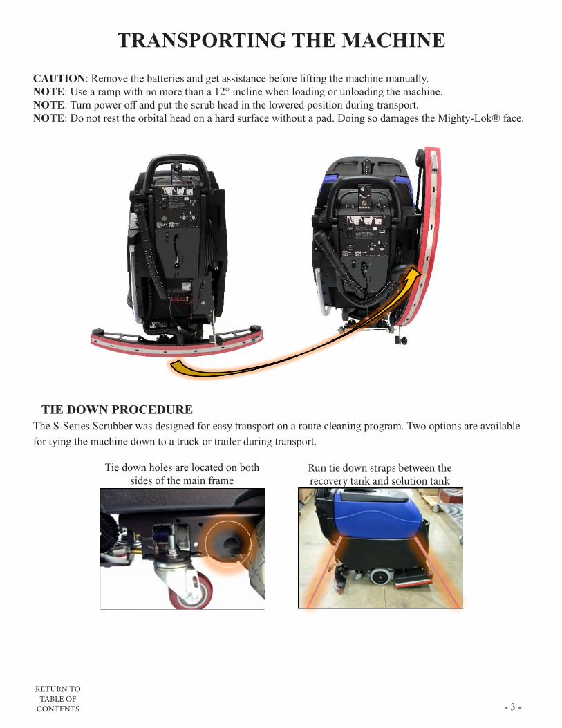
TRANSPORTING THE MACHINECAUTION: Remove the batteries and get assistance before lifting the machine manually.NOTE: Use a ramp with no more than a 12° incline when loading or unloading the machine.NOTE: Turn power off and put the scrub head in the lowered position during transport.NOTE: Do not rest the orbital head on a hard surface without a pad. Doing so damages the Mighty-Lok® face.
TIE DOWN PROCEDURETIE DOWN PROCEDUREThe S-Series Scrubber was designed for easy transport on a route cleaning program. Two options are available for tying the machine down to a truck or trailer during transport.
Tie down holes are located on both sides of the main frame
Run tie down straps between the recovery tank and solution tank

RETURN TO TABLE OF
CONTENTS- 4 -
BATTERIES
WARNING: Battery posts, terminals, and related accessories contain lead and lead compounds, chemicalsknown to the State of California to cause cancer and reproductive harm, and during charging, strong inorganic acid mists containing sulfuric acid are involved, a chemical known to the State of California to cause cancer. Wash hands after handling. For more information go to www.P65Warnings.ca.gov.
WARNING: Batteries emit hydrogen and oxygen gas. -Keep sparks and open flame away. Do not smoke near the machine.-Charge batteries in a well-ventilated area with the battery compartment open.
WARNING: Do not wear jewelry when working near moving or electrical components.CAUTION: Remove the batteries and get assistance before lifting the machine manually.CAUTION: Park and service the machine on a level surface and remove the key.CAUTION: Always wear protective clothing, gloves and goggles when handling and charging batteries.NOTE: All repairs must be performed by a qualified service technician using approved replacement parts.NOTE: Batteries designed for automotive or marine and RV use are not suited for use in floor scrubbers.
SELECTIONThe machine requires four 6 VDC Lead Acid or AGM Deep Cycle batteries designed for floor scrubber use with the following maximum dimensions:• Width: 7 1/8 in (181 mm) • Length: 12 15/16 in (264 mm)• Height: 10 5/8 in (295 mm)
INSTALLATION1. Open the recovery tank.2. Use a lifting device capable of transferring the bat-
teries safely.3. Slide the batteries forward. 4. Connect the batteries in a series to obtain an overall
voltage of 24V on the lugs. 5. Fully charge the batteries before using the machine.

RETURN TO TABLE OF
CONTENTS - 5 -
SERVICING LEAD ACID BATTERIES (NON-HYDROLINK® MODELS)WARNING: Battery posts, terminals, and related accessories contain lead and lead compounds, chemicals
known to the State of California to cause cancer and reproductive harm, and during charging, strong inorganic acid mists containing sulfuric acid are involved, a chemical known to the State of California to cause cancer. Wash hands after handling. For more information go to www.P65Warnings.ca.gov.
WARNING: Batteries emit hydrogen and oxygen gas. -Keep sparks and open flame away. Do not smoke near the machine.-Charge batteries in a well-ventilated area with the battery compartment open.
WARNING: Do not wear jewelry when working near moving or electrical components.CAUTION: Always wear protective clothing, gloves and goggles when handling and charging batteries.
REQUIRED EQUIPMENT• Eye protection• Acid resistant gloves• Distilled water• Baking soda (neutralizes acid spills)
SAFETYNEVER:• Add acid to a battery.• Smoke near batteries.• Charge a frozen battery.• Leave an acid spill unattended.• Store batteries unless they are fully charged.• Charge a battery when the temperature is above 122°F (50°C).• Charge a flooded battery without securing vent caps on the cells.• Place objects on top of batteries, which can cause a short circuit.
ALWAYS:• Neutralize acid spills with baking
soda and water.• Use insulated tools and check that
connections are tight.
Remove the caps and place them upside down to inspect
WATERING• If contact with electrolyte (sulfuric acid) occurs, flush with large amounts of water.• Use only distilled water (tap water can contain contaminants that will damage the battery).• Remove the caps and place them upside down to check electrolyte levels.• For discharged or partially charged batteries, add just enough water to cover the plates.• Fully charge the batteries.• Add distilled water to a level of 1/8” below the vent well.
CLEANING & INSPECTION• Fluid on the top of a battery may mean it is being over-watered or overcharged. • Check cleanliness and keep terminals and connectors free of corrosion.• Clean with a solution of 1 cup baking soda to 1 gallon of water.• Do not allow cleaning solution to get inside the battery.• Rinse with water and dry with a clean cloth.• Keep the area around batteries clean and dry.• Properly secure all vent caps.• Check battery cables and connections. Replace any damaged cables and tighten any loose connections.

RETURN TO TABLE OF
CONTENTS- 6 -
SERVICING LEAD ACID BATTERIES WITH HYDROLINK® WATERING SYSTEM
WARNING: Battery posts, terminals, and related accessories contain lead and lead compounds, chemicals known to the State of California to cause cancer and reproductive harm, and during charging, strong inorganic acid mists containing sulfuric acid are involved, a chemical known to the State of California to cause cancer. Wash hands after handling. For more information go to www.P65Warnings.ca.gov.
1. Position the container of distilled water below the level of the top of the batteries to prevent siphoning.
2. Place the end of the watering system hose in the distilled water and squeeze the bulb to fill the system.
3. Remove the dust cover from the Hydrolink® snake connected to the batteries.
4. Connect the coupler on the Hydrolink® snake to the coupler on the watering system using the quick disconnect fittings.
5. While squeezing the hand pump, observe the flow indicator (spinning red balls). As the batteries begin to fill, the spinning of the flow indicator balls will slow. Batteries are full when the flow indicators completely stop spinning.
NOTE: Battery systems may take more than 1/2 gallon of water once the BatteryShield® light has illuminated. Failure to actuate the hand pump until the flow indicator stops spinning will result in batteries being under or unevenly serviced which will reduce battery life.
6. When the flow indicator stops, and not before, immediately disconnect the couplers by depressing the push button on the watering system coupler.
NOTE: Leaving the watering system connected could result in the batteries being over filled. Disconnecting the watering system before the flow indicator stops spinning will result in batteries being under serviced and battery life will be reduced.
7. Replace the dust cover on the Hydrolink® snake.

RETURN TO TABLE OF
CONTENTS - 7 -
BATTERYSHIELD® AUTOMATED WET BATTERY PROTECTION SYSTEM
Scrubbers equipped with BatteryShield® technology have a sensor on the battery pack and a red LED indicator on the control panel which monitor and communicate low water conditions.
1. When batteries are fully charged and the key is turned on, BatteryShield® will check the water level.• If the LED remains off, there is sufficient water in the batteries.• A solid red LED means BatteryShield® senses a low-water level. The brush motor will be
disabled to prevent battery damage.• A blinking red LED means the BatteryShield® light pipe needs to be cleaned (see below).
NOTE: Failure to clean the HydroLink® light pipe will limit the BatteryShield’s® ability to read the water level and will reduce battery life.
2. Turn the key off and use the HydroLink® single-point battery watering system to fill the batteries.NOTE: Battery packs equipped with BatteryShield® may take more than 1/2 gallon of water after the
BatteryShield® LED has illuminated. Failure to pump the HydroLink™ bulb until it will no longer compress may result in uneven battery servicing and premature battery failure�
3. After completing the HydroLink® watering procedure, cycle the key to verify the LED stays off.

RETURN TO TABLE OF
CONTENTS- 8 -
CLEANING THE BATTERYSHIELD® SENSOR LIGHT PIPEWARNING: Battery posts, terminals, and related accessories contain lead and lead compounds, chemicals
known to the State of California to cause cancer and reproductive harm, and during charging, strong inorganic acid mists containing sulfuric acid are involved, a chemical known to the State of California to cause cancer. Wash hands after handling. For more information go to www.P65Warnings.ca.gov.
WARNING: Do not wear jewelry when working near moving or electrical components.WARNING: Batteries emit hydrogen and oxygen gas.
-Keep sparks and open flame away. Do not smoke near the machine.-Charge batteries in a well-ventilated area with the battery compartment open.
CAUTION: Always wear protective clothing, gloves and goggles when handling and charging batteries.NOTE: Failure to clean the HydroLink® light pipe will limit the BatteryShield’s® ability to read the water level
and will reduce battery life.
1. Remove the cap with the black sensor module, being careful notto damage the yellow floats. Do not remove the black module from the cap assembly.
2. Thoroughly wipe the clear light pipe next to the middle yellowfloat, paying attention to the tip of the pipe.
3. While the cap is still removed, cycle the key and verify the LEDstays on steady. Turn the key off.
4. Carefully align the cap and press it firmly onto the batterymaking sure it is fully seated.
5. Complete the battery servicing procedures above, cycle the key,and verify the light stays off.
6. The machine is ready for use.
RETURN TO TABLE OF
CONTENTS - 9 -
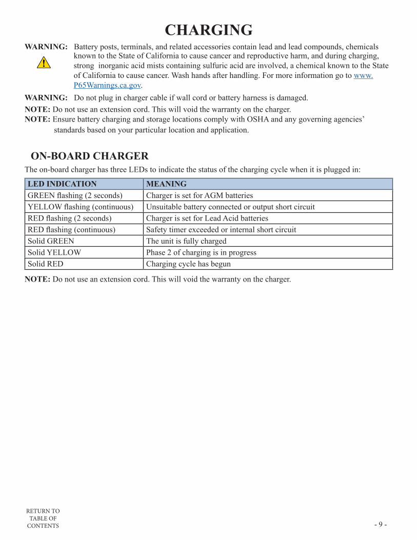
CHARGINGWARNING: Battery posts, terminals, and related accessories contain lead and lead compounds, chemicals
known to the State of California to cause cancer and reproductive harm, and during charging, strong inorganic acid mists containing sulfuric acid are involved, a chemical known to the State of California to cause cancer. Wash hands after handling. For more information go to www.P65Warnings.ca.gov.
WARNING: Do not plug in charger cable if wall cord or battery harness is damaged.NOTE: Do not use an extension cord. This will void the warranty on the charger.NOTE: Ensure battery charging and storage locations comply with OSHA and any governing agencies’
standards based on your particular location and application.
ON-BOARD CHARGERThe on-board charger has three LEDs to indicate the status of the charging cycle when it is plugged in:
LED INDICATION MEANINGGREEN flashing (2 seconds) Charger is set for AGM batteriesYELLOW flashing (continuous) Unsuitable battery connected or output short circuitRED flashing (2 seconds) Charger is set for Lead Acid batteriesRED flashing (continuous) Safety timer exceeded or internal short circuitSolid GREEN The unit is fully chargedSolid YELLOW Phase 2 of charging is in progressSolid RED Charging cycle has begun
NOTE: Do not use an extension cord. This will void the warranty on the charger.

RETURN TO TABLE OF
CONTENTS- 10 -
SETTING THE CHARGER ON MACHINES PURCHASED WITHOUT BATTERIES
Configure the charging profile to the type of batteries installed on the machine. Switch banks SW1 and SW2 are located behind the label on the lower right corner of the charger next to the green LED.
DP2 DP1 CHARGING CURRENTON ON 15AON OFF 20AOFF ON 25AOFF OFF 25A
SW2: Set the charge current according to the battery amp hour rate(Reference CHARGE CURRENT AND BATTERY AMP HOURS table below).
SW1: Set the current profile according to the battery installed.
DP2 DP1 CHARGING CURRENTOFF ON Lead-Acid (Wet) BatteriesOFF OFF AGM FULLRIVERON OFF AGM DISCOVERON ON Gel
CHARGING CURRENTBATTERY AMP HOUR RANGE
(5h) (20h)15A 100-150 Ah 130-180 Ah20A 120-195 Ah 150-240 Ah25A 180-258 Ah 220-315 Ah

RETURN TO TABLE OF
CONTENTS - 11 -
OFF-BOARD CHARGERWARNING: Battery posts, terminals, and related accessories contain lead and lead compounds, chemicals
known to the State of California to cause cancer and reproductive harm, and during charging, strong inorganic acid mists containing sulfuric acid are involved, a chemical known to the State of California to cause cancer. Wash hands after handling. For more information go to www.P65Warnings.ca.gov.
WARNING: Do not plug in charger cable if wall cord or battery harness is damaged.NOTE: Ensure battery charging and storage locations comply with OSHA and any governing agencies’
standards based on your particular location and application.
Set the Battery Type switch to match the battery configuration of the machine.
• Up for Lead Acid batteries.• Down for sealed, maintenance-free AGM batteries
1. Connect the charger to the wall outlet.2. Connect the red plug (pictured below) to the battery harness below the control panel at the rear of the
machine.
Off-board status LEDs:
• Primary (green) LED:• Blinking slowly: Batteries are below 80% of full charge.• Blinking rapidly: Batteries are above 80% of full charge.• Solid: Batteries are fully charged.
• Fault (red) LED:• See the charger manual for fault information.

RETURN TO TABLE OF
CONTENTS- 12 -
PRE-USE SETUP
The key switch is located on the control panel. When the machine is not in use, remove the key and store it in a secure location.
TURNING THE UNIT ON/OFF
CIRCUIT BREAKERSThe circuit breakers on the control panel protect the components from high amp-draw. In particular, the scrub head circuit will draw too many amps when overloaded by improper application setup. Solution flow, floor sur-face, and down-pressure should be considered when operating the machine (example: high down-pressure on a rough floor with no solution flow will overload the circuit). Repeatedly tripping the breaker will cause the need for replacement.
BATTERY POWER LEVEL & FAULT INDICATORBATTERY POWER LEVEL & FAULT INDICATORWhen switched to the ON position, the Battery Power Level Indicator illuminates indicating the battery charge level. A full charge is indicated when all LEDs are lit. As the power level decreases, the LEDs go out from right to left.
When the battery charge is depleted, the last red LED will flash and the brush motor will turn off. The vacuum and traction drive will continue to function allowing final water recovery and transport to the charging station.
NOTE: Using AGM battery-equipped units after the last yellow LED goes out can reduce the life of the batteries.
NOTE: After a fill charge, operate the machine for at least 30 minutes before recharging the batteries again. Do not leave the batteries discharged overnight.
A flashing Battery Power Level Indicator indicates a detected fault. The following is a list of fault codes:
The battery needs to be charged or there is a faulty connection to the battery.
Check the connection to the motor.
The motor has a short circuit.
The controller is being inhibited from driving.
Throttle fault, check the connection.
Controller fault, check connections
Parking brake fault, check the motor connections.
Excessive voltage, check the battery connections.

RETURN TO TABLE OF
CONTENTS - 13 -
DRIVE SYSTEMDRIVE SYSTEMDRIVING OPERATION
1. Bail: Squeezing the Bail activates solution flow, the brush motor, and traction drive.2. Speed Control: Rotate the Speed Control with either thumb.
• Clockwise: Faster• Counter-Clockwise: Slower
3. Reverse Button: Depress Reverse Button and squeeze Bail for reverse operation.
1 2 3
SOLUTION DISTRIBUTIONSOLUTION DISTRIBUTIONFILLING THE SOLUTION TANK
Use liquid detergent in the concentration and manner specified by the manufacturer for a 22-gallon solution tank. Excess foam will damage the vacuum motor. In addition to properly-mixed low-foam detergent, use a small amount of de-foaming liquid in the recovery tank. Never use pure acids.
NOTE: The front fill port strainer blocks debris from falling into the tank. Keep the solution tank free from debris to prevent filter clogs and reduced solution flow.
1. Add water and cleaning agent via the front or rear fill port. Water temperature should not exceed 120°F (50°C).
2. Monitor the solution level through the sight tube and the marks on the tank at the rear of the machine.3. To drain the tank, slide the solution sight tube off of the upper fitting and lower to a drain or mop sink.
FILL PORTS
1 2
3
RETURN TO TABLE OF
CONTENTS- 14 -
INSPECTION & CLEANINGNOTE: If excessive debris is present, drain and flush the solution
tank.
1. Close the shutoff valve.
2. Remove the filter bowl and screen.
3. Clean and rinse any debris in the filter assembly.
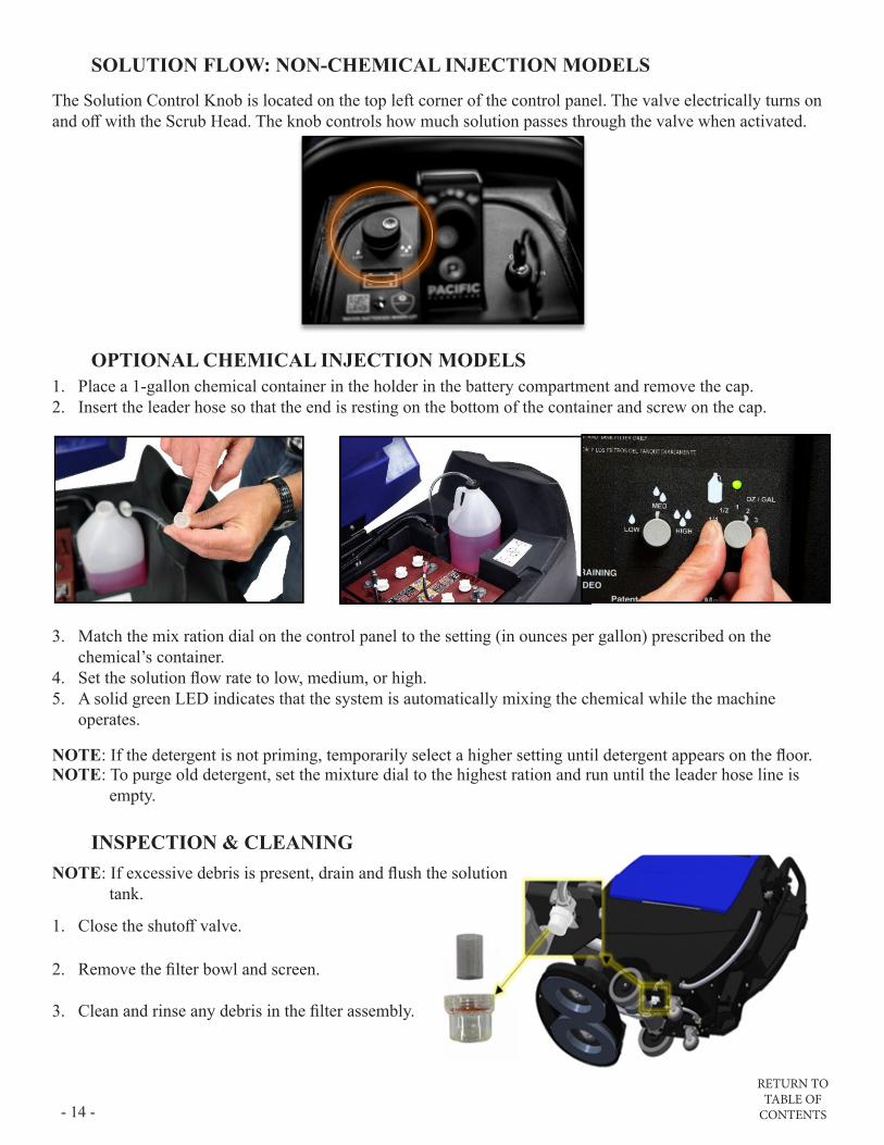
SOLUTION FLOW: NON-CHEMICAL INJECTION MODELS
The Solution Control Knob is located on the top left corner of the control panel. The valve electrically turns on and off with the Scrub Head. The knob controls how much solution passes through the valve when activated.
OPTIONAL CHEMICAL INJECTION MODELS1. Place a 1-gallon chemical container in the holder in the battery compartment and remove the cap.2. Insert the leader hose so that the end is resting on the bottom of the container and screw on the cap.
3. Match the mix ration dial on the control panel to the setting (in ounces per gallon) prescribed on the chemical’s container.
4. Set the solution flow rate to low, medium, or high.5. A solid green LED indicates that the system is automatically mixing the chemical while the machine
operates.
NOTE: If the detergent is not priming, temporarily select a higher setting until detergent appears on the floor.NOTE: To purge old detergent, set the mixture dial to the highest ration and run until the leader hose line is
empty.
RETURN TO TABLE OF
CONTENTS - 15 -
SCRUB DECK SETUPSCRUB DECK SETUP
STANDARD DOWN PRESSURE
MEDIUM DOWN PRESSURE
HEAVY DOWN PRESSURE
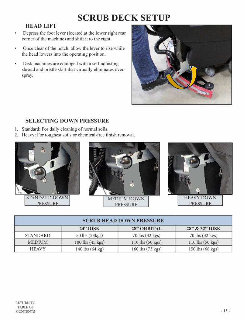
HEAD LIFT• Depress the foot lever (located at the lower right rear
corner of the machine) and shift it to the right.
• Once clear of the notch, allow the lever to rise while the head lowers into the operating position.
• Disk machines are equipped with a self-adjusting shroud and bristle skirt that virtually eliminates over-spray.
SELECTING DOWN PRESSURE1. Standard: For daily cleaning of normal soils.2. Heavy: For toughest soils or chemical-free finish removal.
SCRUB HEAD DOWN PRESSURE24” DISK 28” ORBITAL 28” & 32” DISK
STANDARD 50 lbs (23kgs) 70 lbs (32 kgs) 70 lbs (32 kgs)MEDIUM 100 lbs (45 kgs) 110 lbs (50 kgs) 110 lbs (50 kgs)HEAVY 140 lbs (64 kg) 160 lbs (73 kgs) 150 lbs (68 kgs)

RETURN TO TABLE OF
CONTENTS- 16 -
ORBITAL PADS & CHEMICAL-FREE FINISH REMOVAL (CFR)NOTE: Do not lower the orbital head without a pad installed. Doing so may damage the Mighty-Lok® face.
STANDARD CLEANING OPERATIONS
1. Align the corners of the pad to the corners of the aluminum plate and press to attach.
2. Lower the scrub deck onto the pad.3. Ensure the pad is properly aligned front-to-back and left-to-right.
CHEMICAL-FREE FINISH REMOVAL (CFR) PAD ASSEMBLYA specialized surface preparation pad, in addition to the traditional cleaning pad, is required for chemical-free finish removal. The traditional pad acts as a “backer pad” and compensates for variances in the floor.
1. Place the black retainer pad 2” back from the front of the red scrub pad and the maroon CFR pad to allow water saturation.
2. Align and assemble the pads with the red pad on top and the maroon pad on the bottom facing the floor.
3. Ensure the gap mentioned in step 1 is facing forward and refer to steps 1-3 of “Standard Cleaning Operations” above to install the CFR Pad Assembly.
MACHINE SETUP1. Install the CFR Pad Assembly as described above.
2. Fill the solution tank with clean water.
3. Set the down pressure to Heavy (see “Selecting Down Pressure” above).
4. Set the solution flow to midrange. Adjust as needed for maximum finish removal, using the least amount of water needed for effective rinsing.
5. Adjust the machine speed as required.
RETURN TO TABLE OF
CONTENTS - 17 -
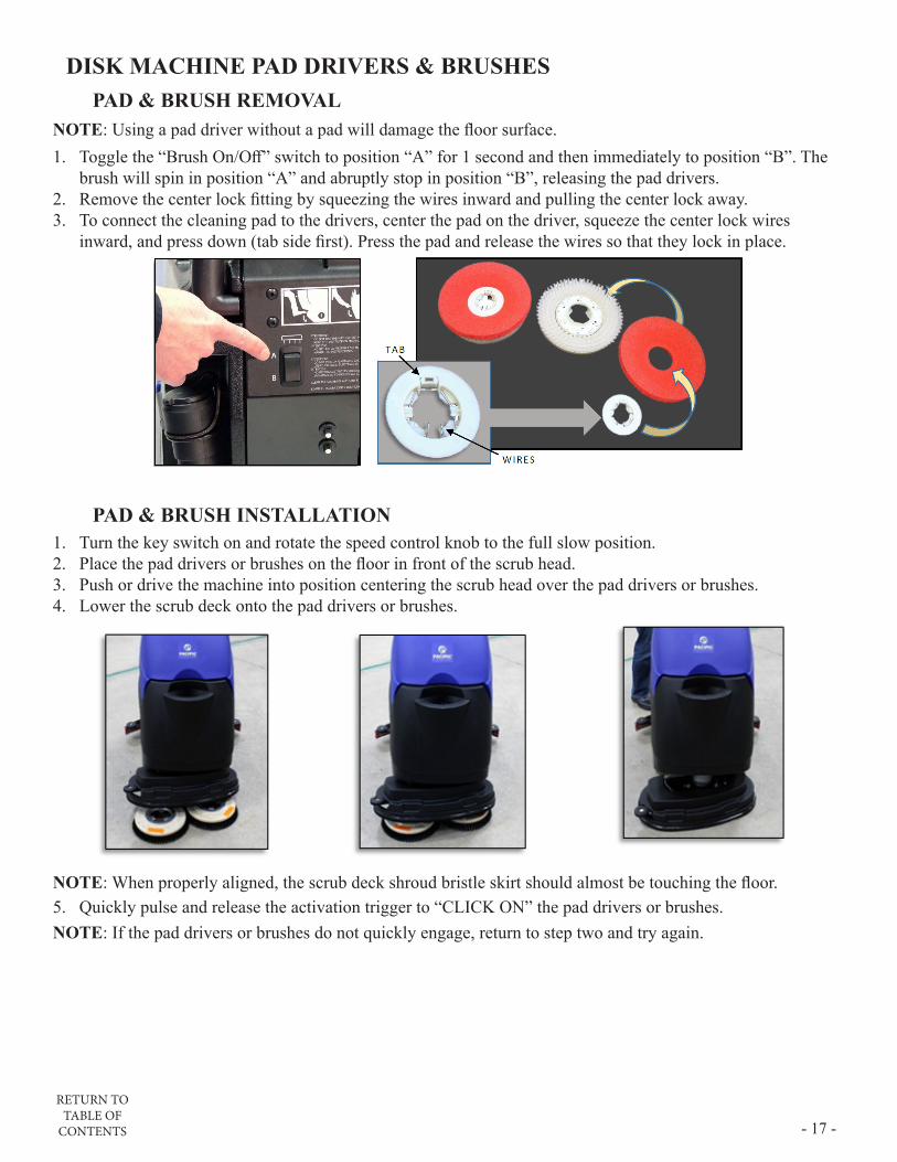
DISK MACHINE PAD DRIVERS & BRUSHESPAD & BRUSH REMOVAL
NOTE: Using a pad driver without a pad will damage the floor surface.1. Toggle the “Brush On/Off” switch to position “A” for 1 second and then immediately to position “B”. The
brush will spin in position “A” and abruptly stop in position “B”, releasing the pad drivers.2. Remove the center lock fitting by squeezing the wires inward and pulling the center lock away.3. To connect the cleaning pad to the drivers, center the pad on the driver, squeeze the center lock wires
inward, and press down (tab side first). Press the pad and release the wires so that they lock in place.
PAD & BRUSH INSTALLATION1. Turn the key switch on and rotate the speed control knob to the full slow position.2. Place the pad drivers or brushes on the floor in front of the scrub head.3. Push or drive the machine into position centering the scrub head over the pad drivers or brushes.4. Lower the scrub deck onto the pad drivers or brushes.
NOTE: When properly aligned, the scrub deck shroud bristle skirt should almost be touching the floor.5. Quickly pulse and release the activation trigger to “CLICK ON” the pad drivers or brushes.NOTE: If the pad drivers or brushes do not quickly engage, return to step two and try again.

RETURN TO TABLE OF
CONTENTS- 18 -
RECOVERY SYSTEMRECOVERY SYSTEMRECOVERY TANK
To drain and rinse the recovery tank:1. Lift the hose off the holder and lower the hose end to the desired drain location.2. Remove the press-fit cap from the drain hose and squeeze the restriction collar to control the flow.3. As the tank drains, lift the recovery tank lid to the fully open position.4. Thoroughly clean and rinse out the sediment from the bottom of the tank with a clean water hose. • Periodically use cleaner and sanitizer with a cloth or sponge to prevent mold and mildew.5. Inspect and clean the debris tray and the vacuum mesh filter screen and ball float system.6. Leave the lid open to dry
1 3
4 5 6
2
OPTIONAL TANK TREATMENT
The Tank Treatment System (TTS) utilizes Bromine tablets (typically used in pools and spas) to kill the odor-causing bacteria in the tank. To ensure that the TTS is prepared to treat your recovery tank:1. Lift the debris tray out and pinch the two tabs sticking through the underside of the tray. 2. Check the size of the Bromine puck. Replace it when it is approximately 25% of its original size. 3. Press the TTS holder and bromine puck back into the debris tray.
CAUTION: Use Bromine only! Do not use chlorine! Chlorine can interact with ammonia-based detergents to cause harmful fumes.
1 2 3

RETURN TO TABLE OF
CONTENTS - 19 -
SQUEEGEE USE1. Lower: Lift the squeegee lever, shift it left, and lower. The vacuum motor will activate.2. Raise: Lift the lever and shift it right. The vacuum motor will run for 10 seconds to prevent recovered
solution from running back out of the hose.
1 2
HEIGHT ADJUSTMENTIf the squeegee blade height requires adjustment, turn the button screws on the squeegee frame assembly clockwise to raise and counter-clockwise to lower the wheels until proper blade deflection is achieved.
Proper blade deflection
SQUEEGEE SYSTEMSQUEEGEE ASSEMBLY SETUP
Inspect and maintain the squeegee system to achieve peak machine performance.
REMOVAL & INSTALLATION• Install: Align the assembly, attach the vacuum hose, and tighten the easy grip knobs.• Remove: Loosen the easy-grip knobs and detach the recovery hose (reverse of installation).

RETURN TO TABLE OF
CONTENTS- 20 -
CLEAN & INSPECT1. Inspect both squeegee blades. If the blade edges are not clearly
defined or are worn halfway through the thickness of the blade, flip the blades to another edge or replace as required.
2. Thoroughly clean and rinse the underside of the squeegee frame, blades and neck.
REMOVE & INSTALL SQUEEGEE BLADES1. Release the over-center latch and slide the band clamp off the hook on the other side. 2. Blades can be flipped length wise or top to bottom to utilize another blade edge.3. Blade installation is the reverse of the removal.

RETURN TO TABLE OF
CONTENTS - 21 -
PAGE INTENTIONALLY BLANK

RETURN TO TABLE OF
CONTENTS
- 22 - RECOMMENDED MAINTENANCESYSTEM REFERENCE SECTION DAILY WEEKLY MONTHLY BIANNUALLY
CONTROL PANEL
INSPECT ALL CONTROLS AND HARDWARE FOR SECURITY AND SERVICEABILITY PARTS DIAGRAMS X
VERIFY PROPER OPERATION OF ALL CONTROLS ALL X
SOLUTION DISTRIBUTION
VERIFY SOLUTION FLOWS AND ADJUSTS AS EXPECTED SOLUTION DISTRIBUTION X
CLEAN AND INSPECT IN-LINE FILTER SOLUTION DISTRIBUTION X
FLUSH TANK WITH FRESH WATER SOLUTION DISTRIBUTION X
SCRUB DECK
RINSE BRUSHES & PADS SCRUB DECK SETUP X
RINSE & DRY SCRUB DECK SCRUB DECK SETUP X
CLEAN MOTOR VENTS PARTS DIAGRAMS X
INSPECT ISOLATORS *(ORBITAL ONLY) PARTS DIAGRAMS X
INSPECT LIFT LINKAGE & PIVOT BLOCKS SCRUB DECK SETUP X
RECOVERY SYSTEM
RINSE & AIR DRY RECOVERY TANK RECOVERY SYSTEM X
CLEAN & INSPECT DEBRIS TRAY RECOVERY SYSTEM X
VERIFY DRAIN HOSE CAP IS SEALED TIGHT WHEN INSTALLED RECOVERY SYSTEM X
INSPECT LID SEAL RECOVERY SYSTEM X
INSPECT / REPLACE BROMINE PUCK *(IF EQUIPPED) RECOVERY SYSTEM X
INSPECT HEPA FILTER *(IF EQUIPPED) RECOVERY SYSTEM X
CLEAN & SANITIZE RECOVERY TANK RECOVERY SYSTEM X
BATTERIES AND CHARGER
INSPECT TERMINALS & CABLES FOR SECURITY, CORROSION, OR DAMAGE BATTERIES X
SERVICE LEAD ACID BATTERIES *(IF EQUIPPED) BATTERIES X
CLEAN ONBOARD CHARGER VENTS *(IF EQUIPPED) PARTS DIAGRAMS X
CLEAN BATTERYSHIELD® LIGHT PIPE *(IF EQUIPPED) BATTERIES X
PERFORM BATTERYSHIELD® OPERATIONAL CHECKS *(IF EQUIPPED) BATTERIES X
SQUEEGEE ASSEMBLY
CLEAN & INSPECT SQUEEGEE ASSEMBLY & BLADES RECOVERY SYSTEM X
INSPECT VACUUM HOSE RECOVERY SYSTEM X
CHASSIS AND UNDERCARRIAGE
CLEAN & INSPECT WHEELS & CASTERS PARTS DIAGRAMS X
CLEAN & INSPECT LINKAGES, CHASSIS & HARDWARE PARTS DIAGRAMS X
CLEAN & INSPECT VISIBLE WIRES FOR DAMAGE & SECURITY PARTS DIAGRAMS X

RETURN TO TABLE OF
CONTENTS
- 23 -
RECOMMENDED SERVICE PARTS(PAGE 1 OF 3)
PART NUMBER DESCRIPTION DIAGRAM CATEGORY WEAR ITEM S-24 S-28 DISK S-32 S-28 ORB OPTIONAL
903046 BELT, V-GROOVE, STRETCH SCRUB HEAD X X
870702 BLADE, FRONT, 35INCH (LINATEX) SQUEEGEE X X
870708 BLADE, FRONT, 35INCH (URETHANE) SQUEEGEE X X
870704 BLADE, FRONT, 40INCH (LINATEX) SQUEEGEE X X X
870710 BLADE, FRONT, 40INCH (URETHANE) SQUEEGEE X X X
870706 BLADE, FRONT, 44.5INCH (LINATEX) SQUEEGEE LINK X X X X X
870712 BLADE, FRONT, 44.5INCH (URETHANE) SQUEEGEE LINK X X X X X
870701 BLADE, REAR, 35INCH (LINATEX) SQUEEGEE X X
870707 BLADE, REAR, 35INCH (URETHANE) SQUEEGEE X X
870703 BLADE, REAR, 40INCH (LINATEX) SQUEEGEE X X X
870709 BLADE, REAR, 40INCH (URETHANE) SQUEEGEE X X X
870705 BLADE, REAR, 44.5INCH (LINATEX) SQUEEGEE LINK X X X X X
870711 BLADE, REAR, 44.5INCH (URETHANE) SQUEEGEE LINK X X X X X
911681 BREAKER, CIRCUIT, 35 AMPS CONTROLS X X
850906 BRUSH CARBON KIT 4 PC 855204 & 875201 SCRUB HEAD X X X X X
870919 BRUSH KIT REPL FOR TRANSAXLE 879203 FRAME ASSEMBLY X X X X X
870909 BRUSH, GRIT, 12 INCH SCRUB HEAD X X
870906 BRUSH, GRIT, 14 INCH SCRUB HEAD X X
870907 BRUSH, GRIT, 16 INCH SCRUB HEAD X X
870908 BRUSH, NYLON, 12 INCH SCRUB HEAD X X
870904 BRUSH, NYLON, 14 INCH SCRUB HEAD X X
870905 BRUSH, NYLON, 16 INCH SCRUB HEAD X X
870902 BRUSH, POLY, 12 INCH SCRUB HEAD X X
870901 BRUSH, POLY, 14 INCH SCRUB HEAD X X
852401 CABLE, LIFT, CLEVIS CONTROLS X X X X
871501 CAP, 38MM, WITH HOLE CHEMICAL INJECTION X X
911622 CIRCUIT BREAKER, 30 AMPS CONTROLS X X X X
912401 CONTACTOR, 24V, 100A ELECTRONICS X X X X
912402 CONTACTOR, 24VDC, 70A ELECTRONICS X X X X
875902 DRIVER, PAD, 14 INCH SCRUB HEAD X X

RETURN TO TABLE OF
CONTENTS
- 24 - RECOMMENDED SERVICE PARTS(PAGE 2 OF 3)
PART NUMBER DESCRIPTION DIAGRAM CATEGORY WEAR ITEM S-24 S-28 DISK S-32 S-28 ORB OPTIONAL
875910 DRIVER, PAD, 16 INCH SCRUB HEAD X X
873304 FILTER, HEPA, MID RECOVERY TANK X X X X X
843319 FILTER, SCREEN, BOWL FRAME ASSEMBLY X X X X X
S764P2 FILTER, STRAINER CHEMICAL INJECTION X X
223370 FLOAT, SHUTOFF RECOVERY TANK X X X X
873314 GASKET, FOAM, VACUUM RECOVERY TANK X X X X
853803 GUIDE, DRIVER SCRUB HEAD X X X X
873802 GUIDE, DRIVER, RH SCRUB HEAD X X X X
853804 GUIDE, PAD, PLASTIC SCRUB HEAD X X X
873801 GUIDE, PAD, PLASTIC SCRUB HEAD X X
854101 HOSE, DRAIN, CAPPED RECOVERY TANK X X X X X
874101 HOSE, SQUEEGEE, 90 CUFF RECOVERY TANK X X X X X
854103 HOSE, VACUUM, 1.5INCH RECOVERY TANK X X X X
854302 HUB, DRIVER, BRUSH SCRUB HEAD X X X
874305 HUB, PULLEY, MACH FLAT SCRUB HEAD X X
874306 HUB, PULLEY, MACH GROOVED SCRUB HEAD X X
875017 KIT CASTER 4 INCH REPLACEMENT FRAME ASSEMBLY X X X X X
875010 KIT, BEARING, REPL, ORBIT SCRUB HEAD X X
875009 KIT, PLATE, REPL, ORBIT SCRUB HEAD X X
875202 MOTOR, VACUUM, 24VDC, 3-STAGE RECOVERY TANK X X X X
555901 PAD 12” BLACK STRIP CASE 5 SCRUB HEAD X X
555941 PAD 12” RED SCRUB CASE 5 SCRUB HEAD X X
555951 PAD 12” WHITE POLISH CASE 5 SCRUB HEAD X X
555902 PAD 14” BLACK STRIP CASE 5 SCRUB HEAD X X
555942 PAD 14” RED SCRUB CASE 5 SCRUB HEAD X X
555952 PAD 14” WHITE POLISH CASE 5 SCRUB HEAD X X
555909 PAD 14”X28” BLACK STRIP CASE 5 SCRUB HEAD X X
555929 PAD 14”X28” MAROON CFR CASE 10 SCRUB HEAD X X
555949 PAD 14”X28” RED SCRUB CASE 5 SCRUB HEAD X X

RETURN TO TABLE OF
CONTENTS
- 25 -
RECOMMENDED SERVICE PARTS(PAGE 3 OF 3)
PART NUMBER DESCRIPTION DIAGRAM CATEGORY WEAR ITEM S-24 S-28 DISK S-32 S-28 ORB OPTIONAL
555969 PAD 14”X28” TURF CASE 4 SCRUB HEAD X X
555959 PAD 14”X28” WHITE POLISH CASE 5 SCRUB HEAD X X
555903 PAD 16” BLACK STRIP CASE 5 SCRUB HEAD X X
555943 PAD 16” RED SCRUB CASE 5 SCRUB HEAD X X
555953 PAD 16” WHITE POLISH CASE 5 SCRUB HEAD X X
875903 PAD, MIGHTYLOK ADH UNIVERSAL SCRUB HEAD X X
875906 PAD, RETAINER, 12X28 SCRUB HEAD X X
857003 PUMP ASSY HAND HYDROLINK BATTERIES X X
858503 SKIRT, BRISTLE SCRUB HEAD X X
878502 SKIRT, BRISTLE SCRUB HEAD X X X
911647 SWITCH, KEY CONTROLS X X X X
911649 SWITCH, ROCKER, AUTO ON-OFF CONTROLS X X X
911653 SWITCH, ROUND, ON – MOM CONTROLS X X X X
911682 SWITCH, SNAP, BENT LEVER FRAME ASSEMBLY X X X X
911646 SWITCH, SNAP, WITH ROLLER CONTROLS X X X X
879201 TRAY, DEBRIS RECOVERY TANK X X X X X
879202 TRAY, PUCK RECOVERY TANK X X X X X
855022 KIT-GUIDE WHEEL REPL, ANTI-RATTLE SCRUB HEAD X X X X X
879705 WHEEL, URETHANE, 222MM FRAME ASSEMBLY X X X X

RETURN TO TABLE OF
CONTENTS
- 26 - TROUBLESHOOTING GUIDEISSUE POTENTIAL CAUSE PROPOSED SOLUTION MANUAL SECTION
INSUFFICIENT WATER TO SCRUB HEAD
SOLUTION FLOW SETTING IS TOO LOW ADJUST SOLUTION CONTROL SOLUTION DISTRIBUTION
SOLUTION TANK IS EMPTY ADD WATER/SOLUTION TO THE TANK SOLUTION DISTRIBUTION
IN-LINE SOLUTION FILTER IS CLOGGED REMOVE AND CLEAN THE FILTER SOLUTION DISTRIBUTION
SOLUTION TUBE IS CLOGGED, KINKED, OR DAMAGED INSPECT TUBES PARTS DIAGRAMS
SOLUTION SHUT OFF VALVE IS CLOSED OPEN VALVE SOLUTION DISTRIBUTION
SOLUTION SOLENOID VALVE MAY BE FAULTY VERIFY OPERATION AND REPLACE IF NECESSARY PARTS DIAGRAMS
POOR WATER RECOVERY
RECOVERY TANK IS FULL EMPTY RECOVERY TANK RECOVERY SYSTEM
DIRTY OR WORN SQUEEGEE BLADES INSPECT AND ROTATE OR REPLACE AS REQUIRED RECOVERY SYSTEM
RECOVERY HOSE LOOSE OR DAMAGED INSPECT AND REPAIR PARTS DIAGRAMS
RECOVERY HOSE OR SQUEEGEE ASSEMBLY HAS AN OBSTRUCTION CLEAR OBSTRUCTIONS FROM RECOVERY SYSTEM PARTS DIAGRAMS
SQUEEGEE ASSEMBLY MAY BE OUT OF ADJUSTMENT ADJUST AS NECESSARY RECOVERY SYSTEM
STUCK OR DAMAGED BALL FLOAT INSPECT AND REPAIR/REPLACE RECOVERY SYSTEM
RECOVERY TANK LID IS NOT SEALING PROPERLY INSPECT RECOVERY LID GASKET. REPAIR OR REPLACE IF NEEDED PARTS DIAGRAM
DRAIN HOSE CAP IS NOT INSTALLED PROPERLY INSTALL DRAIN HOSE SECURELY RECOVERY SYSTEM
LOW BATTERY VOLTAGE CHARGE BATTERIES CHARGING
MACHINE WILL NOT TURN ON
FAULTY KEY SWITCH DIAGNOSE AND REPLACE WIRING DIAGRAMS
DISCHARGED BATTERIES CHARGE BATTERIES CHARGING
LOOSE OR DAMAGED WIRE REPAIR WIRING DIAGRAMS
MACHINE NOT CLEANING FLOOR PROPERLY
WORN PAD OR BRUSH INSPECT AND REPLACE AS REQUIRED SCRUB DECK SETUP
WRONG PAD OR BRUSH FOR APPLICATION CONTACT YOUR LOCAL DISTRIBUTOR FOR RECOMMENDED APPLICATION SCRUB DECK SETUP
INSUFFICIENT CLEANING SOLUTION FOR APPLICATION ADJUST THE MIXTURE AS REQUIRED SOLUTION DISTRIBUTION
EXCESSIVE FOAM IN RECOVERY TANK
IMPROPER DETERGENT TYPE USE A LOW-FOAM DETERGENT OR ADD A DEFOAMING AGENT TO THE RECOVERY TANK. READ ALL CHEMICAL LABELS THOROUGHLY BEFORE USE RECOVERY SYSTEM
MIXTURE SETTING TOO HIGH ON OPTIONAL CHEMICAL INJECTION SYSTEM
USE A LOW-FOAM DETERGENT OR ADD A DEFOAMING AGENT TO THE RECOVERY TANK. READ ALL CHEMICAL LABELS THOROUGHLY BEFORE USE RECOVERY SYSTEM
VACUUM MOTOR WILL NOT RUN
SQUEEGEE LIFT LEVER IS STILL RAISED LOWER SQUEEGEE LEVER RECOVERY SYSTEM
VACUUM RELAY MAY BE FAULTY CONTACT SERVICE TECHNICIAN TO TROUBLESHOOT AND ISOLATE WIRING DIAGRAMS
VACUUM SWITCH OR WIRING MAY BE FAULTY CONTACT SERVICE TECHNICIAN TO TROUBLESHOOT AND ISOLATE WIRING DIAGRAMS
VACUUM MOTOR WILL NOT TURN OFF
STILL IN DELAY MODE ALLOW 10 SECONDS FOR VACUUM TO SHUT DOWN RECOVERY SYSTEM
VACUUM RELAY MAY BE FAULTY CONTACT SERVICE TECHNICIAN TO TROUBLESHOOT AND ISOLATE WIRING DIAGRAM
(PAGE 1 OF 2)
RETURN TO TABLE OF
CONTENTS
- 27 -
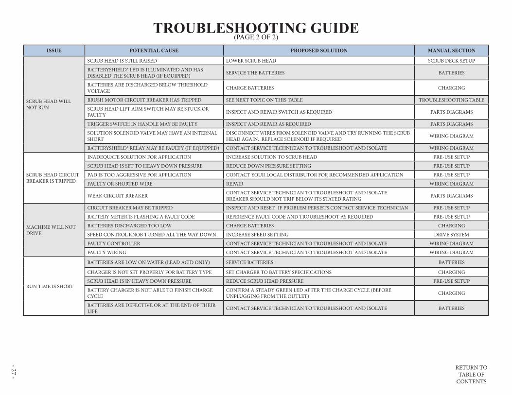
ISSUE POTENTIAL CAUSE PROPOSED SOLUTION MANUAL SECTION
SCRUB HEAD WILL NOT RUN
SCRUB HEAD IS STILL RAISED LOWER SCRUB HEAD SCRUB DECK SETUP
BATTERYSHIELD® LED IS ILLUMINATED AND HAS DISABLED THE SCRUB HEAD (IF EQUIPPED) SERVICE THE BATTERIES BATTERIES
BATTERIES ARE DISCHARGED BELOW THRESHOLD VOLTAGE CHARGE BATTERIES CHARGING
BRUSH MOTOR CIRCUIT BREAKER HAS TRIPPED SEE NEXT TOPIC ON THIS TABLE TROUBLESHOOTING TABLE
SCRUB HEAD LIFT ARM SWITCH MAY BE STUCK OR FAULTY INSPECT AND REPAIR SWITCH AS REQUIRED PARTS DIAGRAMS
TRIGGER SWITCH IN HANDLE MAY BE FAULTY INSPECT AND REPAIR AS REQUIRED PARTS DIAGRAMS
SOLUTION SOLENOID VALVE MAY HAVE AN INTERNAL SHORT
DISCONNECT WIRES FROM SOLENOID VALVE AND TRY RUNNING THE SCRUB HEAD AGAIN. REPLACE SOLENOID IF REQUIRED WIRING DIAGRAM
BATTERYSHIELD® RELAY MAY BE FAULTY (IF EQUIPPED) CONTACT SERVICE TECHNICIAN TO TROUBLESHOOT AND ISOLATE WIRING DIAGRAM
SCRUB HEAD CIRCUIT BREAKER IS TRIPPED
INADEQUATE SOLUTION FOR APPLICATION INCREASE SOLUTION TO SCRUB HEAD PRE-USE SETUP
SCRUB HEAD IS SET TO HEAVY DOWN PRESSURE REDUCE DOWN PRESSURE SETTING PRE-USE SETUP
PAD IS TOO AGGRESSIVE FOR APPLICATION CONTACT YOUR LOCAL DISTRIBUTOR FOR RECOMMENDED APPLICATION PRE-USE SETUP
FAULTY OR SHORTED WIRE REPAIR WIRING DIAGRAM
WEAK CIRCUIT BREAKER CONTACT SERVICE TECHNICIAN TO TROUBLESHOOT AND ISOLATE. BREAKER SHOULD NOT TRIP BELOW ITS STATED RATING PARTS DIAGRAMS
MACHINE WILL NOT DRIVE
CIRCUIT BREAKER MAY BE TRIPPED INSPECT AND RESET. IF PROBLEM PERSISTS CONTACT SERVICE TECHNICIAN PRE-USE SETUP
BATTERY METER IS FLASHING A FAULT CODE REFERENCE FAULT CODE AND TROUBLESHOOT AS REQUIRED PRE-USE SETUP
BATTERIES DISCHARGED TOO LOW CHARGE BATTERIES CHARGING
SPEED CONTROL KNOB TURNED ALL THE WAY DOWN INCREASE SPEED SETTING DRIVE SYSTEM
FAULTY CONTROLLER CONTACT SERVICE TECHNICIAN TO TROUBLESHOOT AND ISOLATE WIRING DIAGRAM
FAULTY WIRING CONTACT SERVICE TECHNICIAN TO TROUBLESHOOT AND ISOLATE WIRING DIAGRAM
RUN TIME IS SHORT
BATTERIES ARE LOW ON WATER (LEAD ACID ONLY) SERVICE BATTERIES BATTERIES
CHARGER IS NOT SET PROPERLY FOR BATTERY TYPE SET CHARGER TO BATTERY SPECIFICATIONS CHARGING
SCRUB HEAD IS IN HEAVY DOWN PRESSURE REDUCE SCRUB HEAD PRESSURE PRE-USE SETUP
BATTERY CHARGER IS NOT ABLE TO FINISH CHARGE CYCLE
CONFIRM A STEADY GREEN LED AFTER THE CHARGE CYCLE (BEFORE UNPLUGGING FROM THE OUTLET) CHARGING
BATTERIES ARE DEFECTIVE OR AT THE END OF THEIR LIFE CONTACT SERVICE TECHNICIAN TO TROUBLESHOOT AND ISOLATE BATTERIES
TROUBLESHOOTING GUIDE(PAGE 2 OF 2)

RETURN TO TABLE OF
CONTENTS
- 28 - BATTERIES, BATTERYSHIELDBATTERIES, BATTERYSHIELD®® & HYDROLINK & HYDROLINK®®
BATTERYSHIELD® SENSOR IS MATED AND CALIBRATED TO THE MANIFOLD (BATT CAP) FROM THE FACTORY. SENSOR AND CAP MUST BE REPLACED AS AN ASSEMBLY – DO NOT REMOVE SENSOR FROM CAP
8
7 COMES WITH 4 MANIFOLDS (BATT CAPS), SERVICING TUBE (NOT PICTURED), AND HAND PUMP
ITEM QTY PART NUMBER DESCRIPTION
1 4 871301 BATTERY, 6V, 260AH, LA
2 4 871302 BATTERY, 6V, 250AH, MF (NOT SHOWN, OPTIONAL)
3 1 858202 FOAM, SPACER, BATTERY
4 3 911640 HARNESS, CONN, BATTERY
5 1 911641 HARNESS, CONN, BATTERY
6 1 878520 SENSOR ASSY BATTERYSHIELD FIELD REPLACE
7 1 879002 COMPLETE SETS MANIFOLDS (BATT CAP), SERVICE TUBE & PUMP
8 1 857003 PUMP ASSY HAND HYDROLINK
9 1 855605 MANIFOLD INDIV HYDROLINK (BATT CAP)
PARTS DIAGRAMS
RETURN TO TABLE OF
CONTENTS
- 29 -
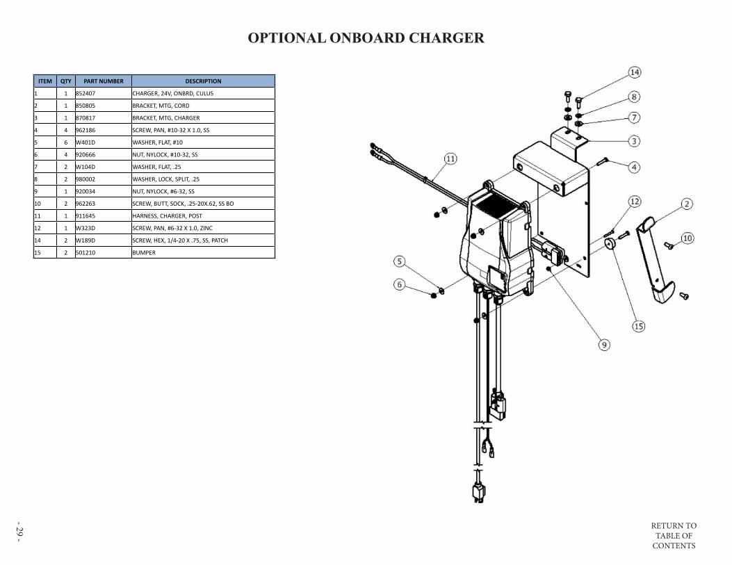
OPTIONAL ONBOARD CHARGEROPTIONAL ONBOARD CHARGER
ITEM QTY PART NUMBER DESCRIPTION
1 1 852407 CHARGER, 24V, ONBRD, CULUS
2 1 850805 BRACKET, MTG, CORD
3 1 870817 BRACKET, MTG, CHARGER
4 4 962186 SCREW, PAN, #10-32 X 1.0, SS
5 6 W401D WASHER, FLAT, #10
6 4 920666 NUT, NYLOCK, #10-32, SS
7 2 W104D WASHER, FLAT, .25
8 2 980002 WASHER, LOCK, SPLIT, .25
9 1 920034 NUT, NYLOCK, #6-32, SS
10 2 962263 SCREW, BUTT, SOCK, .25-20X.62, SS BO
11 1 911645 HARNESS, CHARGER, POST
12 1 W323D SCREW, PAN, #6-32 X 1.0, ZINC
14 2 W189D SCREW, HEX, 1/4-20 X .75, SS, PATCH
15 2 501210 BUMPER

RETURN TO TABLE OF
CONTENTS
- 30 - S-24 DISK CONTROLS(SEE ADDITIONAL DIAGRAM FOR MODELS EQUIPPED WITH BATTERYSHIELD® OR CHEMICAL INJECTION)
CONTROLS
RETURN TO TABLE OF
CONTENTS
- 31 -
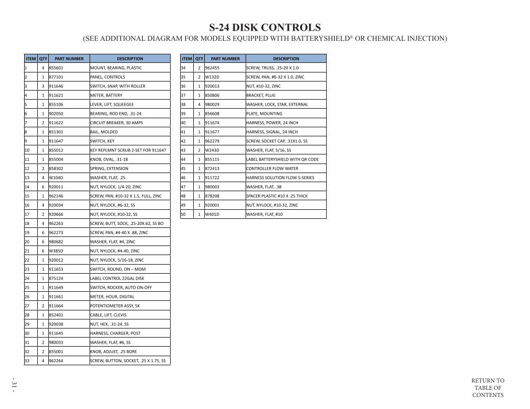
S-24 DISK CONTROLS(SEE ADDITIONAL DIAGRAM FOR MODELS EQUIPPED WITH BATTERYSHIELD® OR CHEMICAL INJECTION)
ITEM QTY PART NUMBER DESCRIPTION
1 4 855601 MOUNT, BEARING, PLASTIC
2 1 877101 PANEL, CONTROLS
3 3 911646 SWITCH, SNAP, WITH ROLLER
4 1 911621 METER, BATTERY
5 1 855106 LEVER, LIFT, SQUEEGEE
6 1 902050 BEARING, ROD END, .31-24
7 2 911622 CIRCUIT BREAKER, 30 AMPS
8 1 851301 BAIL, MOLDED
9 1 911647 SWITCH, KEY
10 1 855012 KEY REPLMNT SCRUB 2-SET FOR 911647
11 1 855004 KNOB, OVAL, .31-18
12 2 858302 SPRING, EXTENSION
13 4 W104D WASHER, FLAT, .25
14 6 920011 NUT, NYLOCK, 1/4-20, ZINC
15 1 962146 SCREW, PAN, #10-32 X 1.5, FULL, ZINC
16 4 920034 NUT, NYLOCK, #6-32, SS
17 2 920666 NUT, NYLOCK, #10-32, SS
18 4 962263 SCREW, BUTT, SOCK, .25-20X.62, SS BO
19 6 962273 SCREW, PAN, #4-40 X .88, ZINC
20 6 980682 WASHER, FLAT, #4, ZINC
21 6 W385D NUT, NYLOCK, #4-40, ZINC
22 1 920012 NUT, NYLOCK, 5/16-18, ZINC
23 1 911653 SWITCH, ROUND, ON – MOM
24 1 875124 LABEL CONTROL 22GAL DISK
25 1 911649 SWITCH, ROCKER, AUTO ON-OFF
26 1 911661 METER, HOUR, DIGITAL
27 2 911664 POTENTIOMETER ASSY, 5K
28 1 852401 CABLE, LIFT, CLEVIS
29 1 920038 NUT, HEX, .31-24, SS
30 1 911645 HARNESS, CHARGER, POST
31 2 980033 WASHER, FLAT, #6, SS
32 2 855001 KNOB, ADJUST, .25 BORE
33 4 962264 SCREW, BUTTON, SOCKET, .25 X 1.75, SS
ITEM QTY PART NUMBER DESCRIPTION
34 2 962455 SCREW, TRUSS, .25-20 X 1.0
35 2 W132D SCREW, PAN, #6-32 X 1.0, ZINC
36 1 920013 NUT, #10-32, ZINC
37 1 850806 BRACKET, PLUG
38 4 980029 WASHER, LOCK, STAR, EXTERNAL
39 1 856608 PLATE, MOUNTING
40 1 911674 HARNESS, POWER, 24 INCH
41 1 911677 HARNESS, SIGNAL, 24 INCH
42 1 962279 SCREW, SOCKET CAP, .31X1.0, SS
43 2 W243D WASHER, FLAT, 5/16, SS
44 1 855115 LABEL BATTERYSHIELD WITH QR CODE
45 1 872413 CONTROLLER FLOW WATER
46 1 911722 HARNESS SOLUTION FLOW S-SERIES
47 1 980003 WASHER, FLAT, .38
48 1 878208 SPACER PLASTIC #10 X .25 THICK
49 1 920001 NUT, NYLOCK, #10-32, ZINC
50 1 W401D WASHER, FLAT, #10
RETURN TO TABLE OF
CONTENTS
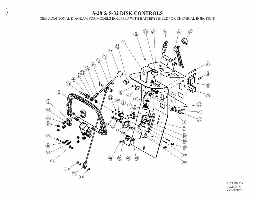
- 32 - S-28 & S-32 DISK CONTROLS(SEE ADDITIONAL DIAGRAM FOR MODELS EQUIPPED WITH BATTERYSHIELD® OR CHEMICAL INJECTION)

RETURN TO TABLE OF
CONTENTS
- 33 -
S-28 & S-32 DISK CONTROLS(SEE ADDITIONAL DIAGRAM FOR MODELS EQUIPPED WITH BATTERYSHIELD® OR CHEMICAL INJECTION)
ITEM QTY PART NUMBER DESCRIPTION
1 4 855601 MOUNT, BEARING, PLASTIC
2 1 877101 PANEL, CONTROLS
3 3 911646 SWITCH, SNAP, WITH ROLLER
4 1 911621 METER, BATTERY
5 1 855106 LEVER, LIFT, SQUEEGEE
6 1 902050 BEARING, ROD END, .31-24
7 1 911622 CIRCUIT BREAKER, 30 AMPS
8 1 851301 BAIL, MOLDED
9 1 911647 SWITCH, KEY
10 1 855012 KEY REPLMNT SCRUB 2-SET FOR 911647
11 1 855004 KNOB, OVAL, .31-18
12 2 858302 SPRING, EXTENSION
13 4 W104D WASHER, FLAT, .25
14 6 920011 NUT, NYLOCK, 1/4-20, ZINC
15 1 962146 SCREW, PAN, #10-32 X 1.5, FULL, ZINC
16 4 920034 NUT, NYLOCK, #6-32, SS
17 2 920666 NUT, NYLOCK, #10-32, SS
18 4 962263 SCREW, BUTT, SOCK, .25-20X.62, SS BO
19 6 962273 SCREW, PAN, #4-40 X .88, ZINC
20 6 980682 WASHER, FLAT, #4, ZINC
21 6 W385D NUT, NYLOCK, #4-40, ZINC
22 1 920012 NUT, NYLOCK, 5/16-18, ZINC
23 1 911653 SWITCH, ROUND, ON – MOM
24 1 875124 LABEL CONTROL 22GAL DISK
25 1 911649 SWITCH, ROCKER, AUTO ON-OFF
26 1 911661 METER, HOUR, DIGITAL
27 2 911664 POTENTIOMETER ASSY, 5K
28 1 852401 CABLE, LIFT, CLEVIS
29 1 920038 NUT, HEX, .31-24, SS
30 1 911645 HARNESS, CHARGER, POST
31 2 980033 WASHER, FLAT, #6, SS
32 2 855001 KNOB, ADJUST, .25 BORE
33 4 962264 SCREW, BUTTON, SOCKET, .25 X 1.75, SS
ITEM QTY PART NUMBER DESCRIPTION
34 2 962455 SCREW, TRUSS, .25-20 X 1.0
35 2 W132D SCREW, PAN, #6-32 X 1.0, ZINC
36 1 920013 NUT, #10-32, ZINC
37 1 850806 BRACKET, PLUG
38 2 911681 BREAKER, CIRCUIT, 35 AMPS
39 4 980029 WASHER, LOCK, STAR, EXTERNAL
40 1 856608 PLATE, MOUNTING
41 1 911675 HARNESS, POWER, 28 & 32 INCH
42 1 911678 HARNESS, SIGNAL, 28 & 32 INCH
43 1 962279 SCREW, SOCKET CAP, .31X1.0, SS
44 2 W243D WASHER, FLAT, 5/16, SS
45 1 872413 CONTROLLER FLOW WATER
46 1 980003 WASHER, FLAT, .38
47 1 911722 HARNESS SOLUTION FLOW S-SERIES
48 1 878208 SPACER PLASTIC #10 X .25 THICK
49 1 920001 NUT, NYLOCK, #10-32, ZINC
50 1 W401D WASHER, FLAT, #10

RETURN TO TABLE OF
CONTENTS
- 34 - S-28 ORBITAL CONTROLS(SEE ADDITIONAL DIAGRAM FOR MODELS EQUIPPED WITH BATTERYSHIELD® OR CHEMICAL INJECTION)

RETURN TO TABLE OF
CONTENTS
- 35 -
S-28 ORBITAL CONTROLS(SEE ADDITIONAL DIAGRAM FOR MODELS EQUIPPED WITH BATTERYSHIELD® OR CHEMICAL INJECTION)
ITEM QTY PART NUMBER DESCRIPTION
1 4 855601 MOUNT, BEARING, PLASTIC
2 1 877101 PANEL, CONTROLS
3 3 911646 SWITCH, SNAP, WITH ROLLER
4 1 911621 METER, BATTERY
5 1 855106 LEVER, LIFT, SQUEEGEE
6 1 902050 BEARING, ROD END, .31-24
7 2 911622 CIRCUIT BREAKER, 30 AMPS
8 1 851301 BAIL, MOLDED
9 1 911647 SWITCH, KEY
10 1 855012 KEY REPLMNT SCRUB 2-SET FOR 911647
11 1 855004 KNOB, OVAL, .31-18
12 2 858302 SPRING, EXTENSION
13 4 W104D WASHER, FLAT, .25
14 6 920011 NUT, NYLOCK, 1/4-20, ZINC
15 1 962146 SCREW, PAN, #10-32 X 1.5, FULL, ZINC
16 4 920034 NUT, NYLOCK, #6-32, SS
17 2 920666 NUT, NYLOCK, #10-32, SS
18 4 962263 SCREW, BUTT, SOCK, .25-20X.62, SS BO
19 6 962273 SCREW, PAN, #4-40 X .88, ZINC
20 6 980682 WASHER, FLAT, #4, ZINC
21 6 W385D NUT, NYLOCK, #4-40, ZINC
22 1 920012 NUT, NYLOCK, 5/16-18, ZINC
23 1 911653 SWITCH, ROUND, ON – MOM
24 1 911661 METER, HOUR, DIGITAL
25 2 911664 POTENTIOMETER ASSY, 5K
26 1 852401 CABLE, LIFT, CLEVIS
27 1 920038 NUT, HEX, .31-24, SS
28 1 911645 HARNESS, CHARGER, POST
29 2 980033 WASHER, FLAT, #6, SS
30 2 855001 KNOB, ADJUST, .25 BORE
31 4 962264 SCREW, BUTTON, SOCKET, .25 X 1.75, SS
32 2 962455 SCREW, TRUSS, .25-20 X 1.0
33 2 W132D SCREW, PAN, #6-32 X 1.0, ZINC
ITEM QTY PART NUMBER DESCRIPTION
34 1 920013 NUT, #10-32, ZINC
35 1 850806 BRACKET, PLUG
36 1 875125 LABEL CONTROL 22GAL ORB
37 4 980029 WASHER, LOCK, STAR, EXTERNAL
38 1 856608 PLATE, MOUNTING
39 1 911676 HARNESS, POWER, 28 ORBITAL
40 1 911679 HARNESS, SIGNAL, 28 ORBITAL
41 1 962279 SCREW, SOCKET CAP, .31X1.0, SS
42 2 W243D WASHER, FLAT, 5/16, SS
43 1 855115 LABEL BATTERYSHIELD WITH QR CODE
44 1 872413 CONTROLLER FLOW WATER
45 1 911722 HARNESS SOLUTION FLOW S-SERIES
46 1 980003 WASHER, FLAT, .38
47 1 878208 SPACER PLASTIC #10 X .25 THICK
48 1 920001 NUT, NYLOCK, #10-32, ZINC
49 1 W401D WASHER, FLAT, #10

RETURN TO TABLE OF
CONTENTS
- 36 - OPTIONAL BATTERYSHIELD & CHEMICAL INJECTION CONTROLS
ITEM QTY PART NUMBER DESCRIPTION
1 1 872401 CONTROLLER, DISPENSING
2 2 875001 KNOB, .25 BORE, SMALL
3 1 875104 LABEL, CONTROL, SOLUTION
4 1 875107 LED, RED, 24VDC
5 1 855115 LABEL BATTERYSHIELD WITH QR CODE
6 1 911684 HARNESS, BATTERYSHIELD
7 1 911680 HARNESS, SOLUTION CONTROL
8 1 855012 KEY REPLMNT SCRUB 2-SET FOR 911647

RETURN TO TABLE OF
CONTENTS
- 37 -
S-24 ELECTRONICS(SEE ADDITIONAL DIAGRAM FOR MODELS EQUIPPED WITH BATTERYSHIELD® OR CHEMICAL INJECTION)
ITEM QTY PART NUMBER DESCRIPTION
1 1 879101 CONTROLLER, I-DRIVE, MID
2 1 879801 PANEL, ELECTRONICS
3 1 912402 CONTACTOR, 24VDC, 70A
4 2 912401 CONTACTOR, 24V, 100A
5 2 858501 STAND-OFF, INSULATED, .25-20
6 6 W104D WASHER, FLAT, .25
7 6 980002 WASHER, LOCK, SPLIT, .25
8 4 W169D SCREW, HEX, .25-20 X .50
9 2 W323D SCREW, PAN, #6-32 X 1.0, ZINC
10 2 980025 WASHER, SPLIT LOCK, #6, ZINC
11 4 W401D WASHER, FLAT, #10
12 6 962363 SCREW, PAN, #10-32 X .50, SS
13 6 980022 WASHER, LOCK, SPLIT, #10
14 2 962276 SCREW, SET, .25-20 X 1.25, ZINC, PATCH
15 2 924083 NUT .25-20 FLEX LOCK ZINC
ELECTRONICS

RETURN TO TABLE OF
CONTENTS
- 38 - S-28 & S-32 DISK ELECTRONICS(SEE ADDITIONAL DIAGRAM FOR MODELS EQUIPPED WITH BATTERYSHIELD® OR CHEMICAL INJECTION)
ITEM QTY PART NUMBER DESCRIPTION
1 1 879101 CONTROLLER, I-DRIVE, MID
2 1 879801 PANEL, ELECTRONICS
3 1 912402 CONTACTOR, 24VDC, 70A
4 2 912401 CONTACTOR, 24V, 100A
5 2 858501 STAND-OFF, INSULATED, .25-20
6 6 W104D WASHER, FLAT, .25
7 6 980002 WASHER, LOCK, SPLIT, .25
8 4 W169D SCREW, HEX, .25-20 X .50
9 2 W323D SCREW, PAN, #6-32 X 1.0, ZINC
10 2 980025 WASHER, SPLIT LOCK, #6, ZINC
11 4 W401D WASHER, FLAT, #10
12 6 962363 SCREW, PAN, #10-32 X .50, SS
13 6 980022 WASHER, LOCK, SPLIT, #10
14 2 962276 SCREW, SET, .25-20 X 1.25, ZINC, PATCH
15 2 924083 NUT .25-20 FLEX LOCK ZINC

RETURN TO TABLE OF
CONTENTS
- 39 -
S-28 ORBITAL ELECTRONICS(SEE ADDITIONAL DIAGRAM FOR MODELS EQUIPPED WITH BATTERYSHIELD® OR CHEMICAL INJECTION)
ITEM QTY PART NUMBER DESCRIPTION
1 1 879101 CONTROLLER, I-DRIVE, MID
2 1 879801 PANEL, ELECTRONICS
3 1 912402 CONTACTOR, 24VDC, 70A
4 2 912401 CONTACTOR, 24V, 100A
5 2 858501 STAND-OFF, INSULATED, .25-20
6 6 W104D WASHER, FLAT, .25
7 6 980002 WASHER, LOCK, SPLIT, .25
8 4 W169D SCREW, HEX, .25-20 X .50
9 2 W323D SCREW, PAN, #6-32 X 1.0, ZINC
10 2 980025 WASHER, SPLIT LOCK, #6, ZINC
11 4 W401D WASHER, FLAT, #10
12 6 962363 SCREW, PAN, #10-32 X .50, SS
13 6 980022 WASHER, LOCK, SPLIT, #10
14 2 962276 SCREW, SET, .25-20 X 1.25, ZINC, PATCH
15 2 924083 NUT .25-20 FLEX LOCK ZINC

RETURN TO TABLE OF
CONTENTS
- 40 - OPTIONAL BATTERYSHIELD® ELECTRONICS
ITEM QTY PART NUMBER DESCRIPTION
1 2 980025 WASHER, SPLIT LOCK, #6, ZINC
2 1 911685 RELAY, 24VDC, BATTERYSHIELD
3 2 W315D SCREW, PAN, #6-32 X .50, BLK
4 2 980033 WASHER, FLAT, #6, SS

RETURN TO TABLE OF
CONTENTS
- 41 -
FRAME ASSEMBLY
ITEM QTY PART NUMBER DESCRIPTION
1 1 873201 FRAME, SCRUBBER, 20 TRACT
2 4 W243D WASHER, FLAT, 5/16, SS
3 8 980094 WASHER, SPLIT LOCK, .31, SS
4 4 962269 SCREW, HEX, .31-18 X .75, SS
5 1 855014 KIT VALVE SCRUBBER REPLMNT
6 1 859402 VALVE SOLENOID 24V NONADJ
7 14 W189D SCREW, HEX, 1/4-20 X .75, SS, PATCH
8 1 980029 WASHER, LOCK, STAR, EXTERNAL
9 14 920011 NUT, NYLOCK, 1/4-20, ZINC
10 8 W104D WASHER, FLAT, .25
11 1 852101 CLAMP, WIRE, P-SHAPED
12 1 224130 - 20.0” TUBING, 1/2”
13 4 S453P CLAMP, HOSE, WORM
14 1 224130 - 14.0” TUBING, 1/2”
15 1 843319 FILTER, SCREEN, BOWL
16 1 224130 - 5.12” TUBING, 1/2”
17 2 850807 BRACKET, RETAINING, TRANS
18 1 879203 TRANSAXLE, 24VDC
19 1 870919 BRUSH KIT REPL FOR TRANSAXLE 879203
20 1 875204 MOTOR REPL FOR TRANSAXLE 879203
21 2 915007 KEY, WOODRUFF, 5MM
22 2 879705 WHEEL, URETHANE, 222MM
23 2 920648 NUT, M12, NYLOCK
24 2 875017 KIT CASTER 4 INCH REPLACEMENT
25 2 877502 RIG CASTER 4INCH WITH AXLE
26 2 879711 WHEEL CASTER 4INCH
27 1 911682 SWITCH, SNAP, BENT LEVER
28 1 856608 PLATE, MOUNTING
29 2 W385D NUT, NYLOCK, #4-40, ZINC
30 2 962273 SCREW, PAN, #4-40 X .88, ZINC
31 1 873804 GROMMET .50ID .81HOLE .25THK
RETURN TO TABLE OF
CONTENTS
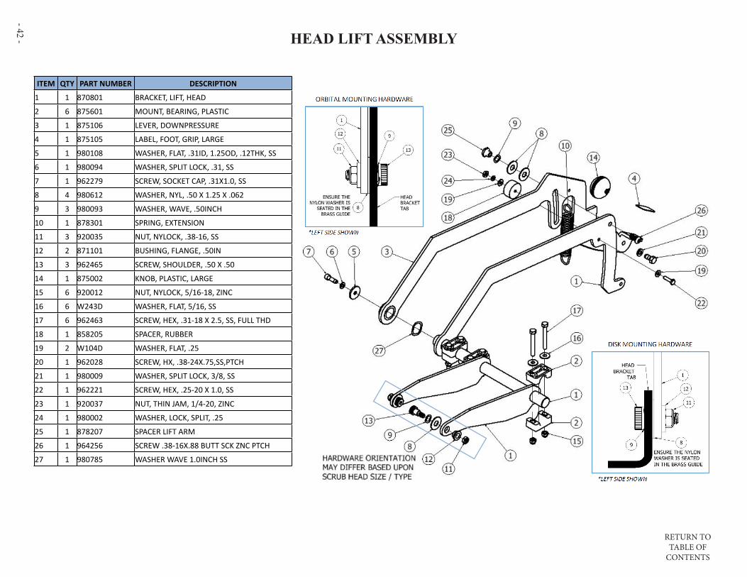
- 42 - HEAD LIFT ASSEMBLY
ITEM QTY PART NUMBER DESCRIPTION
1 1 870801 BRACKET, LIFT, HEAD
2 6 875601 MOUNT, BEARING, PLASTIC
3 1 875106 LEVER, DOWNPRESSURE
4 1 875105 LABEL, FOOT, GRIP, LARGE
5 1 980108 WASHER, FLAT, .31ID, 1.25OD, .12THK, SS
6 1 980094 WASHER, SPLIT LOCK, .31, SS
7 1 962279 SCREW, SOCKET CAP, .31X1.0, SS
8 4 980612 WASHER, NYL, .50 X 1.25 X .062
9 3 980093 WASHER, WAVE, .50INCH
10 1 878301 SPRING, EXTENSION
11 3 920035 NUT, NYLOCK, .38-16, SS
12 2 871101 BUSHING, FLANGE, .50IN
13 3 962465 SCREW, SHOULDER, .50 X .50
14 1 875002 KNOB, PLASTIC, LARGE
15 6 920012 NUT, NYLOCK, 5/16-18, ZINC
16 6 W243D WASHER, FLAT, 5/16, SS
17 6 962463 SCREW, HEX, .31-18 X 2.5, SS, FULL THD
18 1 858205 SPACER, RUBBER
19 2 W104D WASHER, FLAT, .25
20 1 962028 SCREW, HX, .38-24X.75,SS,PTCH
21 1 980009 WASHER, SPLIT LOCK, 3/8, SS
22 1 962221 SCREW, HEX, .25-20 X 1.0, SS
23 1 920037 NUT, THIN JAM, 1/4-20, ZINC
24 1 980002 WASHER, LOCK, SPLIT, .25
25 1 878207 SPACER LIFT ARM
26 1 964256 SCREW .38-16X.88 BUTT SCK ZNC PTCH
27 1 980785 WASHER WAVE 1.0INCH SS

RETURN TO TABLE OF
CONTENTS
- 43 -
SOLUTION TANK
ITEM QTY PART NUMBER DESCRIPTION
1 1 878601 TANK, SOLUTION, 22 GAL
2 1 870805 BRACKET, SUPPORT, LEVER
3 1 879004 TUBE, SIGHT, REPLACEMENT
4 2 853303 FITTING, STR, BM12, PM08
5 1 W189D SCREW, HEX, 1/4-20 X .75, SS, PATCH
6 1 920037 NUT, THIN JAM, 1/4-20, ZINC
7 1 962455 SCREW, TRUSS, .25-20 X 1.0
8 4 225670 PAD, WIRE TIE
9 1 S453P CLAMP, HOSE, WORM
10 4 962271 SCREW, PAN, #10 X .38L, ZINC
11 1 875103 LABEL, INSTRUCTION, BATTERY
12 1 879401 VALVE, SHUT-OFF, BALL
13 1 875011 KIT, STRAINER, PORT, FILL
14 1 872304 COVER, PORT, FILL
15 1 874501 HINGE, TANK, RECOVERY
16 5 962269 SCREW, HEX, .31-18 X .75, SS
17 5 980094 WASHER, SPLIT LOCK, .31, SS
18 5 W243D WASHER, FLAT, 5/16, SS
19 1 W401D WASHER, FLAT, #10
20 4 962460 SCREW, #8X.75, PHIL TRUSS SS
21 1 980002 WASHER, LOCK, SPLIT, .25
22 1 870819 BRACKET, RETENTION, HANGER

RETURN TO TABLE OF
CONTENTS
- 44 -
*** PRIOR TO SERIAL NUMBER 123255 ***RECOVERY TANK AND VACUUM
ITEM DESCRIPTION QTY
877802 SHEET INSTR MID-SCRUBBER VAC MTR REPL 1
873314 GASKET, FOAM, VACUUM 1
875202 MTR, VAC, 24VDC, 3STG - KIT 875023 AVAIL 1
873315 FOAM BARRIER NOISE MID 1
853305 FOAM,NOISE,VACUUM 1
AVAILABLE VACUUM MOTOR KIT - #875023
ITEM QTY PART NUMBER DESCRIPTION
1 2 223370 FLOAT, SHUTOFF
2 2 853304 FITTING, STR, BM24, PM20
3 1 873401 GASKET, COVER, PRESS-IN
4 1 854103 HOSE, VACUUM, 1.5INCH
5 1 874101 HOSE, SQUEEGEE, 90 CUFF
6 1 874102 HOSE SQUEEGEE MID CHEM RESIST
7 1 852101 CLAMP, WIRE, P-SHAPED
8 4 855603 MOUNT, RUBBER, .25-20
9 2 962462 SCREW, SHOULDER, .38 X 1.75, SS
10 1 878602 TANK, RECOVERY, 22 GAL
11 3 W104D WASHER, FLAT, .25
12 12 980002 WASHER, LOCK, SPLIT, .25
13 9 920037 NUT, THIN JAM, 1/4-20, ZINC
14 1 870806 BRACKET, MTG, ISOLATOR
15 4 S611A CLAMP, HOSE, WORM
16 1 854101 HOSE, DRAIN, CAPPED
17 1 851501 CAP HOSE DRAIN - REPL FOR 854101
18 1 854104 HOSE DRAIN CAPPED CHEM RESIST
19 1 872412 CABLE RETENTION MID LONG
20 4 W189D SCREW, HEX, 1/4-20 X .75, SS, PATCH
21 8 964224 SCREW, PAN, #10 X .5, SELF TAPPING
22 1 853308 FITTING, MODIFIED
23 1 872301 COVER, TANK, RECOVERY
24 1 879201 TRAY, DEBRIS
25 1 877007 PUCK, BROMINE (4-PACK)
26 1 873304 FILTER, HEPA, MID
27 1 879202 TRAY, PUCK
28 2 875202 MOTOR, VACUUM, 24VDC, 3-STAGE
29 2 980106 WASHER, FLAT, .25ID, 1.0OD, .12THK, SS
30 3 962269 SCREW, HEX, .31-18 X .75, SS
31 3 W243D WASHER, FLAT, 5/16, SS
ITEM QTY PART NUMBER DESCRIPTION
32 3 980094 WASHER, SPLIT LOCK, .31, SS
33 1 875110 LABEL, INSTRUCT, BROMINE
34 1 872303 COVER, MTG, VACUUM
35 1 873314 GASKET, FOAM, VACUUM
36 1 853305 FOAM, NOISE, VACUUM
37 1 874501 HINGE, TANK, RECOVERY
38 2 856803 PLUG HOLE 1 INCH BLACK
39 1 873315 FOAM BARRIER NOISE
40 1 858506 STRAP SUPPORT HOSE
RETURN TO TABLE OF
CONTENTS
- 45 -
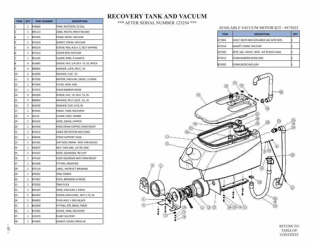
*** AFTER SERIAL NUMBER 123254 ***RECOVERY TANK AND VACUUM
ITEM DESCRIPTION QTY
877802 SHEET INSTR MID-SCRUBBER VAC MTR REPL 1
873314 GASKET, FOAM, VACUUM 1
875202 MTR, VAC, 24VDC, 3STG - KIT 875023 AVAIL 1
873315 FOAM BARRIER NOISE MID 1
853305 FOAM,NOISE,VACUUM 1
AVAILABLE VACUUM MOTOR KIT - #875023
ITEM QTY PART NUMBER DESCRIPTION
1 1 878602 TANK, RECOVERY, 22 GAL
2 1 895113 LABEL PACIFIC 4INCH ROUND
3 1 853305 FOAM, NOISE, VACUUM
4 1 873314 GASKET, FOAM, VACUUM
5 4 964224 SCREW, PAN, #10 X .5, SELF TAPPING
6 1 872312 COVER MTG VACUUM
7 1 852101 CLAMP, WIRE, P-SHAPED
8 4 W189D SCREW, HEX, 1/4-20 X .75, SS, PATCH
9 4 980002 WASHER, LOCK, SPLIT, .25
10 3 W104D WASHER, FLAT, .25
11 2 875202 MOTOR, VACUUM, 24VDC, 3-STAGE
12 1 873304 FILTER, HEPA, MID
13 1 873315 FOAM BARRIER NOISE
14 3 962269 SCREW, HEX, .31-18 X .75, SS
15 3 980094 WASHER, SPLIT LOCK, .31, SS
16 3 W243D WASHER, FLAT, 5/16, SS
17 1 874501 HINGE, TANK, RECOVERY
18 3 S611A CLAMP, HOSE, WORM
19 1 854101 HOSE, DRAIN, CAPPED
20 1 854104 HOSE DRIAN CAPPED CHEM RESIST
21 1 872412 CABLE RETENTION MID LONG
22 1 858506 STRAP SUPPORT HOSE
23 1 851501 CAP HOSE DRAIN - REPL FOR 854101
24 1 920037 NUT, THIN JAM, 1/4-20, ZINC
25 1 874101 HOSE, SQUEEGEE, 90 CUFF
26 1 874102 HOSE SQUEEGEE MID CHEM RESIST
27 1 853308 FITTING, MODIFIED
28 1 875110 LABEL, INSTRUCT, BROMINE
29 1 879201 TRAY, DEBRIS
30 1 877007 PUCK, BROMINE (4-PACK)
31 1 879202 TRAY, PUCK
32 1 854103 HOSE, VACUUM, 1.5INCH
33 2 962462 SCREW, SHOULDER, .38 X 1.75, SS
34 2 856803 PLUG HOLE 1 INCH BLACK
35 1 853304 FITTING, STR, BM24, PM20
36 1 872301 COVER, TANK, RECOVERY
37 1 223370 FLOAT, SHUTOFF
38 1 873401 GASKET, COVER, PRESS-IN
RETURN TO TABLE OF
CONTENTS
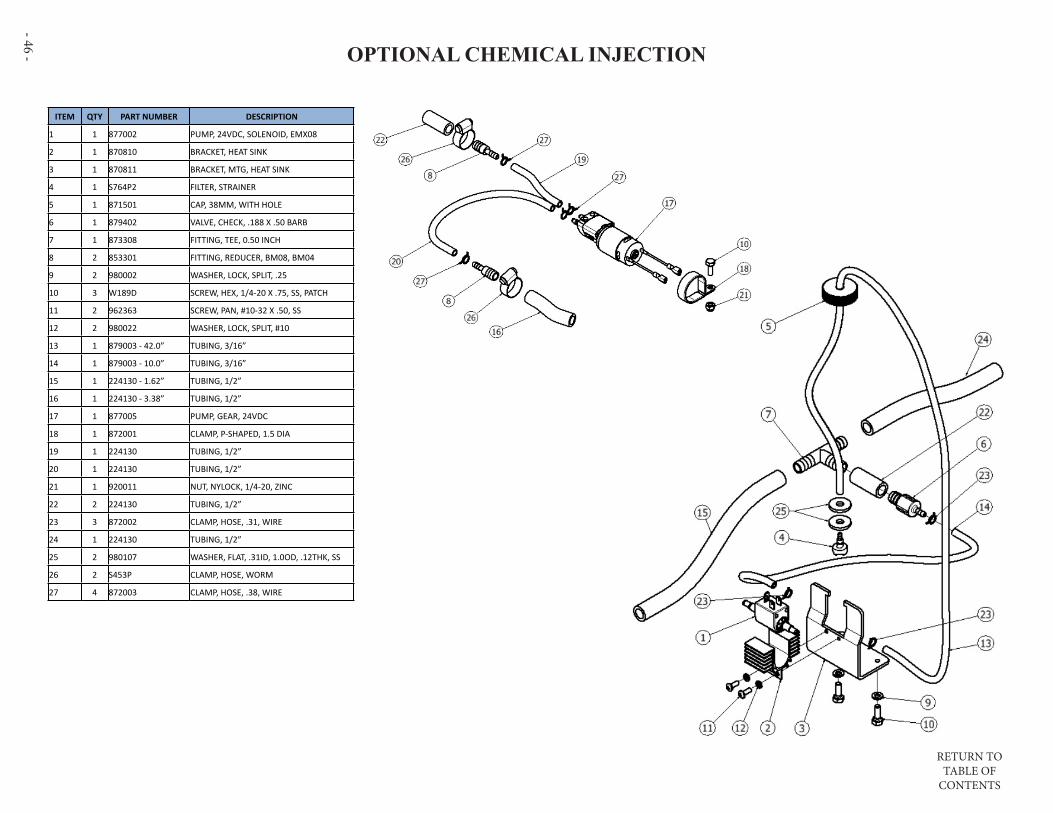
- 46 - OPTIONAL CHEMICAL INJECTION
ITEM QTY PART NUMBER DESCRIPTION
1 1 877002 PUMP, 24VDC, SOLENOID, EMX08
2 1 870810 BRACKET, HEAT SINK
3 1 870811 BRACKET, MTG, HEAT SINK
4 1 S764P2 FILTER, STRAINER
5 1 871501 CAP, 38MM, WITH HOLE
6 1 879402 VALVE, CHECK, .188 X .50 BARB
7 1 873308 FITTING, TEE, 0.50 INCH
8 2 853301 FITTING, REDUCER, BM08, BM04
9 2 980002 WASHER, LOCK, SPLIT, .25
10 3 W189D SCREW, HEX, 1/4-20 X .75, SS, PATCH
11 2 962363 SCREW, PAN, #10-32 X .50, SS
12 2 980022 WASHER, LOCK, SPLIT, #10
13 1 879003 - 42.0” TUBING, 3/16”
14 1 879003 - 10.0” TUBING, 3/16”
15 1 224130 - 1.62” TUBING, 1/2”
16 1 224130 - 3.38” TUBING, 1/2”
17 1 877005 PUMP, GEAR, 24VDC
18 1 872001 CLAMP, P-SHAPED, 1.5 DIA
19 1 224130 TUBING, 1/2”
20 1 224130 TUBING, 1/2”
21 1 920011 NUT, NYLOCK, 1/4-20, ZINC
22 2 224130 TUBING, 1/2”
23 3 872002 CLAMP, HOSE, .31, WIRE
24 1 224130 TUBING, 1/2”
25 2 980107 WASHER, FLAT, .31ID, 1.0OD, .12THK, SS
26 2 S453P CLAMP, HOSE, WORM
27 4 872003 CLAMP, HOSE, .38, WIRE
RETURN TO TABLE OF
CONTENTS
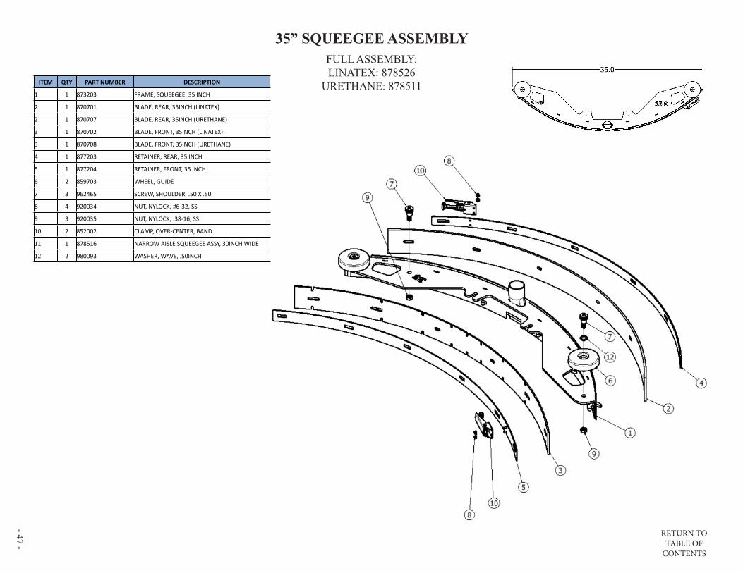
- 47 -
35” SQUEEGEE ASSEMBLYFULL ASSEMBLY:LINATEX: 878526
URETHANE: 878511ITEM QTY PART NUMBER DESCRIPTION
1 1 873203 FRAME, SQUEEGEE, 35 INCH
2 1 870701 BLADE, REAR, 35INCH (LINATEX)
2 1 870707 BLADE, REAR, 35INCH (URETHANE)
3 1 870702 BLADE, FRONT, 35INCH (LINATEX)
3 1 870708 BLADE, FRONT, 35INCH (URETHANE)
4 1 877203 RETAINER, REAR, 35 INCH
5 1 877204 RETAINER, FRONT, 35 INCH
6 2 859703 WHEEL, GUIDE
7 3 962465 SCREW, SHOULDER, .50 X .50
8 4 920034 NUT, NYLOCK, #6-32, SS
9 3 920035 NUT, NYLOCK, .38-16, SS
10 2 852002 CLAMP, OVER-CENTER, BAND
11 1 878516 NARROW AISLE SQUEEGEE ASSY, 30INCH WIDE
12 2 980093 WASHER, WAVE, .50INCH

RETURN TO TABLE OF
CONTENTS
- 48 - 40” SQUEEGEE ASSEMBLYFULL ASSEMBLY:LINATEX: 878527
URETHANE: 878512ITEM QTY PART NUMBER DESCRIPTION
1 1 873204 FRAME, SQUEEGEE, 40 INCH
2 1 870703 BLADE, REAR, 40INCH (LINATEX)
2 1 870709 BLADE, REAR, 40INCH (URETHANE)
3 1 870704 BLADE, FRONT, 40INCH (LINATEX)
3 1 870710 BLADE, FRONT, 40INCH (URETHANE)
4 1 877201 RETAINER, REAR, 40 INCH
5 1 877202 RETAINER, FRONT, 40 INCH
6 2 859703 WHEEL, GUIDE
7 3 962465 SCREW, SHOULDER, .50 X .50
8 4 920034 NUT, NYLOCK, #6-32, SS
9 3 920035 NUT, NYLOCK, .38-16, SS
10 2 852002 CLAMP, OVER-CENTER, BAND
11 2 980093 WASHER, WAVE, .50INCH

RETURN TO TABLE OF
CONTENTS
- 49 -
45” SQUEEGEE ASSEMBLYFULL ASSEMBLY:LINATEX: 878528
URETHANE: 878513ITEM QTY PART NUMBER DESCRIPTION
1 1 873205 FRAME SQUEEGEE 45 INCH
2 1 870705 BLADE REAR 45 INCH LINATEX
2 1 870711 BLADE REAR 45 INCH URETHANE
3 1 870706 BLADE FRONT 45 INCH LINARD
3 1 870712 BLADE FRONT 45 INCH URETHANE
4 1 877205 RETAINER, REAR, 45 INCH
5 1 877206 RETAINER, FRONT, 45 INCH
6 2 859703 WHEEL, GUIDE
7 3 962465 SCREW, SHOULDER, .50 X .50
8 4 920034 NUT, NYLOCK, #6-32, SS
9 3 920035 NUT, NYLOCK, .38-16, SS
10 2 852002 CLAMP, OVER-CENTER, BAND
11 2 980093 WASHER, WAVE, .50INCH
RETURN TO TABLE OF
CONTENTS
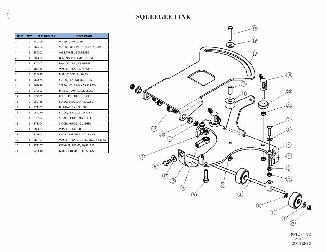
- 50 - SQUEEGEE LINK
ITEM QTY PART NUMBER DESCRIPTION
1 2 849709 WHEEL, 2 OD, .31 ID
2 2 962464 SCREW, BUTTON, .31-18 X 1.25, ZINC
3 1 850501 AXLE, WHEEL, SQUEEGEE
4 1 902051 BEARING, ROD END, .38 FEM
5 1 870802 BRACKET, LINK, SQUEEGEE
6 8 980105 WASHER, PLASTIC, THRUST
7 3 920035 NUT, NYLOCK, .38-16, SS
8 1 962075 SCREW, HEX, 3/8-16 X 1.5, SS
9 1 962028 SCREW, HX, .38-24X.75,SS,PTCH
10 1 870803 BRACKET, SWING, SQUEEGEE
11 1 877501 GUIDE, ROLLER, SQUEEGEE
12 2 962465 SCREW, SHOULDER, .50 X .50
13 2 871101 BUSHING, FLANGE, .50IN
14 1 962270 SCREW, HEX, 5/16-18X1.75,SS
15 1 878504 STRAP, GROUNDING, STATIC
16 1 878204 SPACER, GUIDE, SQUEEGEE
17 1 980003 WASHER, FLAT, .38
18 2 875003 KNOB, THREADED, .31-18 X 1.5
19 1 980107 WASHER, FLAT, .31ID, 1.0OD, .12THK, SS
20 2 877207 RETAINER, FRAME, SQUEEGEE
21 9 920040 NUT, .31-18, NYLOCK, SS, LOW

RETURN TO TABLE OF
CONTENTS
- 51 -
PAGE INTENTIONALLY BLANK

RETURN TO TABLE OF
CONTENTS
- 52 - S-24 SCRUB HEAD(PAGE 2 OF 2)
ITEM QTY PART NUMBER DESCRIPTION
1 2 870902 BRUSH, POLY, 12 INCH
2 2 870908 BRUSH, NYLON, 12 INCH
3 2 870909 BRUSH, GRIT, 12 INCH
4 1 859703 WHEEL, GUIDE
5 1 875019 KIT SKIRT REPLACEMENT (ITEMS 6 - 10)
6 4 962263 SCREW, BUTT, SOCK, .25-20X.62, SS BO
7 4 920665 NUT, NYLOCK, 1/4-20, SS
8 8 W104D WASHER, FLAT, .25
9 1 872305 SHROUD, HEAD, 24INCH
10 1 858503 SKIRT, BRISTLE
11 13 962274 SCREW, FLAT, SOCK, .25-20X.62, SS, PATCH
12 2 873302 FITTING, TEE, PM02XBM04
13 2 875901 DRIVER, PAD, 12INCH, BRISTLE
14 1 204179 - 16.0” TUBING, 1/4”
15 1 204179 - 9.75” TUBING, 1/4”
16 1 204179 - 8.25” TUBING, 1/4”
17 1 873308 FITTING, TEE, 0.50 INCH
18 2 853301 FITTING, REDUCER, BM08, BM04
19 2 224130 - 1.75” TUBING, 1/2”
20 1 878205 SPACER, WHEEL, GUIDE
21 1 224130 - 20.0” TUBING, 1/2”
AVAILABLE PADSPART NUMBER DESCRIPTION
555901 PAD 12” BLACK STRIP CASE 5
555941 PAD 12” RED SCRUB CASE 5
555951 PAD 12” WHITE POLISH CASE 5
(PAGE 1 OF 2)
SCRUB HEADS

RETURN TO TABLE OF
CONTENTS
- 53 -
S-24 SCRUB HEAD(PAGE 2 OF 2)
S-24 SCRUB HEAD
ITEM QTY PART NUMBER DESCRIPTION
1 1 876602 PLATE, MTG, 24 INCH
2 3 858203 SPACER, WHEEL, GUIDE
3 8 W104D WASHER, FLAT, .25
4 9 W243D WASHER, FLAT, 5/16, SS
5 1 853803 GUIDE, DRIVER
6 2 873801 GUIDE, PAD, PLASTIC
7 3 857501 ROLLER, PLASTIC
8 13 962274 SCREW, FLAT, SOCK, .25-20X.62, SS, PATCH
9 3 962270 SCREW, HEX, 5/16-18X1.75,SS
10 3 920012 NUT, NYLOCK, 5/16-18, ZINC
11 1 855204 MOTOR, 24V, 2200 RPM, 1HP
12 1 850906 BRUSH CARBON KIT 4 PC 855204 & 875201
13 1 903046 BELT, V-GROOVE, STRETCH
14 1 876606 PLATE, COVER, 24 INCH
15 2 877701 SHAFT, PULLEY, HEAD
16 6 902035 BEARING, .5 ID, 1.1875 OD
17 3 876901 PULLEY, IDLER
18 3 877302 RING, RETAINING, INT, 1.12 DIA
19 6 878201 SPACER, IDLER
20 3 878202 SPACER, IDLER, PLAIN
21 1 876902 PULLEY, MOTOR, DRIVE
22 1 980108 WASHER, FLAT, .31ID, 1.25OD, .12THK, SS
23 1 915006 KEY, 8MM X 7MM X 28MM
24 4 902053 BEARING, .75 ID, DBL SEAL
25 2 980003 WASHER, FLAT, .38
26 2 878203 SPACER, BEARING
27 1 874306 HUB, PULLEY, MACH GROOVED
28 1 874305 HUB, PULLEY, MACH FLAT
29 1 870807 BRACKET, SUPPORT, HEAD 24
30 4 964008 SCREW, HEX, M6 X 25, SS, PATCH
31 1 964060 SCREW, HEX, M8-1.25 X 20, SS
ITEM QTY PART NUMBER DESCRIPTION
32 2 920039 NUT, .62-18, NYLOCK, LOW
33 1 870814 BRACKET, SUPPORT, 24XM
34 2 920035 NUT, NYLOCK, .38-16, SS
35 1 873802 GUIDE, DRIVER, RH
36 1 878206 SPACER, MOTOR, 24INCH
37 6 W189D SCREW, HEX, 1/4-20 X .75, SS, PATCH
38 6 980002 WASHER, LOCK, SPLIT, .25
39 2 857009 PLUNGER BALL PRESS-IN

RETURN TO TABLE OF
CONTENTS
- 54 -
*** PRIOR TO SERIAL NUMBER 121567 ***S-28 DISK SCRUB HEAD

RETURN TO TABLE OF
CONTENTS
- 55 -
ITEM QTY PART NUMBER DESCRIPTION
1 2 870901 BRUSH, POLY, 14 INCH
1 2 870904 BRUSH, NYLON, 14 INCH
1 2 870906 BRUSH, GRIT, 14 INCH
1 2 875902 DRIVER, PAD, 14 INCH
5 1 855022 KIT GUIDE WHEEL REPLACEMENT ANIT-RATTLE
6 2 915008 KEY, SQUARE, 5MM X 5 X 40MM
7 3 858203 SPACER, WHEEL, GUIDE
8 1 875020 KIT SHROUD S28 REPLACEMENT (ITEMS 9 - 13)
9 1 872302 SHROUD, HEAD, 28INCH
10 1 878502 SKIRT, BRISTLE
11 4 962263 SCREW, BUTT, SOCK, .25-20X.62, SS BO
12 4 920665 NUT, NYLOCK, 1/4-20, SS
13 20 W104D WASHER, FLAT, .25
14 2 962466 SCREW, HEX, M8-1.25 X 25, SS, PATCH
15 6 W243D WASHER, FLAT, 5/16, SS
16 2 980094 WASHER, SPLIT LOCK, .31, SS
17 1 853803 GUIDE, DRIVER
18 2 853804 GUIDE, PAD, PLASTIC
19 2 857501 ROLLER, PLASTIC
20 6 962274 SCREW, FLAT, SOCK, .25-20X.62, SS, PATCH
21 2 962270 SCREW, HEX, 5/16-18X1.75,SS
23 2 920012 NUT, NYLOCK, 5/16-18, ZINC
24 1 870804 BRACKET, SUPPORT, HEAD
25 4 871101 BUSHING, FLANGE, .50IN
26 4 962465 SCREW, SHOULDER, .50 X .50
27 2 873301 FITTING, TEE, .25INCH
28 2 876604 PLATE, MOUNTING, GIMBLE
29 2 980107 WASHER, FLAT, .31ID, 1.0OD, .12THK, SS
30 4 920035 NUT, NYLOCK, .38-16, SS
31 4 962221 SCREW, HEX, .25-20 X 1.0, SS
32 12 980002 WASHER, LOCK, SPLIT, .25
33 4 920037 NUT, THIN JAM, 1/4-20, ZINC
34 2 875203 MOTOR GEAR BRUSH MRP15 SERVICE
35 1 850906 BRUSH CARBON KIT 4 PC 855204 & 875201
ITEM QTY PART NUMBER DESCRIPTION
36 1 876601 PLATE, MTG, 28INCH
37 1 873802 GUIDE, DRIVER, RH
38 1 204179 - 15.2” TUBING, 1/4”
39 1 204179 - 6.0” TUBING, 1/4”
40 1 204179 - 5.5” TUBING, 1/4”
41 4 875603 BUMPER, RUBBER, WITH STUD
42 1 873308 FITTING, TEE, 0.50 INCH
43 2 853301 FITTING, REDUCER, BM08, BM04
44 2 224130 - 1.75” TUBING, 1/2”
45 8 964448 SCREW, HEX, M6 X 16, SS, PATCH
46 2 870818 BRACKET, RETAINING, SEAL
47 1 224130 - 20.0” TUBING, 1/2”
48 4 920011 NUT, NYLOCK, 1/4-20, ZINC
49 2 854302 HUB, DRIVER, BRUSH
50 2 857009 PLUNGER BALL PRESS-IN
AVAILABLE PADS
*** PRIOR TO SERIAL NUMBER 121567 ***S-28 DISK SCRUB HEAD
PART NUMBER DESCRIPTION
555902 PAD 14” BLACK STRIP CASE 5
555942 PAD 14” RED SCRUB CASE 5
555952 PAD 14” WHITE POLISH CASE 5

RETURN TO TABLE OF
CONTENTS
- 56 -
*** AFTER SERIAL NUMBER 121567 ***S-28 DISK SCRUB HEAD
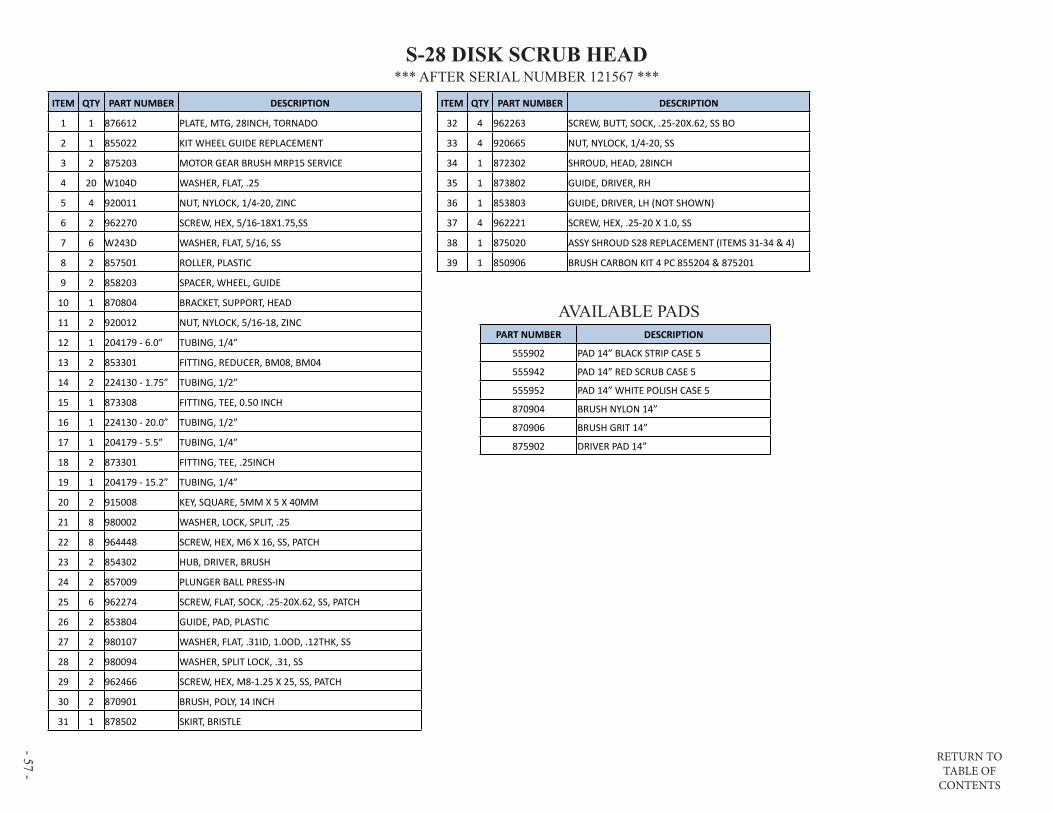
RETURN TO TABLE OF
CONTENTS
- 57 -
*** AFTER SERIAL NUMBER 121567 ***S-28 DISK SCRUB HEAD
PART NUMBER DESCRIPTION
555902 PAD 14” BLACK STRIP CASE 5
555942 PAD 14” RED SCRUB CASE 5
555952 PAD 14” WHITE POLISH CASE 5
870904 BRUSH NYLON 14”
870906 BRUSH GRIT 14”
875902 DRIVER PAD 14”
AVAILABLE PADS
ITEM QTY PART NUMBER DESCRIPTION
1 1 876612 PLATE, MTG, 28INCH, TORNADO
2 1 855022 KIT WHEEL GUIDE REPLACEMENT
3 2 875203 MOTOR GEAR BRUSH MRP15 SERVICE
4 20 W104D WASHER, FLAT, .25
5 4 920011 NUT, NYLOCK, 1/4-20, ZINC
6 2 962270 SCREW, HEX, 5/16-18X1.75,SS
7 6 W243D WASHER, FLAT, 5/16, SS
8 2 857501 ROLLER, PLASTIC
9 2 858203 SPACER, WHEEL, GUIDE
10 1 870804 BRACKET, SUPPORT, HEAD
11 2 920012 NUT, NYLOCK, 5/16-18, ZINC
12 1 204179 - 6.0” TUBING, 1/4”
13 2 853301 FITTING, REDUCER, BM08, BM04
14 2 224130 - 1.75” TUBING, 1/2”
15 1 873308 FITTING, TEE, 0.50 INCH
16 1 224130 - 20.0” TUBING, 1/2”
17 1 204179 - 5.5” TUBING, 1/4”
18 2 873301 FITTING, TEE, .25INCH
19 1 204179 - 15.2” TUBING, 1/4”
20 2 915008 KEY, SQUARE, 5MM X 5 X 40MM
21 8 980002 WASHER, LOCK, SPLIT, .25
22 8 964448 SCREW, HEX, M6 X 16, SS, PATCH
23 2 854302 HUB, DRIVER, BRUSH
24 2 857009 PLUNGER BALL PRESS-IN
25 6 962274 SCREW, FLAT, SOCK, .25-20X.62, SS, PATCH
26 2 853804 GUIDE, PAD, PLASTIC
27 2 980107 WASHER, FLAT, .31ID, 1.0OD, .12THK, SS
28 2 980094 WASHER, SPLIT LOCK, .31, SS
29 2 962466 SCREW, HEX, M8-1.25 X 25, SS, PATCH
30 2 870901 BRUSH, POLY, 14 INCH
31 1 878502 SKIRT, BRISTLE
ITEM QTY PART NUMBER DESCRIPTION
32 4 962263 SCREW, BUTT, SOCK, .25-20X.62, SS BO
33 4 920665 NUT, NYLOCK, 1/4-20, SS
34 1 872302 SHROUD, HEAD, 28INCH
35 1 873802 GUIDE, DRIVER, RH
36 1 853803 GUIDE, DRIVER, LH (NOT SHOWN)
37 4 962221 SCREW, HEX, .25-20 X 1.0, SS
38 1 875020 ASSY SHROUD S28 REPLACEMENT (ITEMS 31-34 & 4)
39 1 850906 BRUSH CARBON KIT 4 PC 855204 & 875201
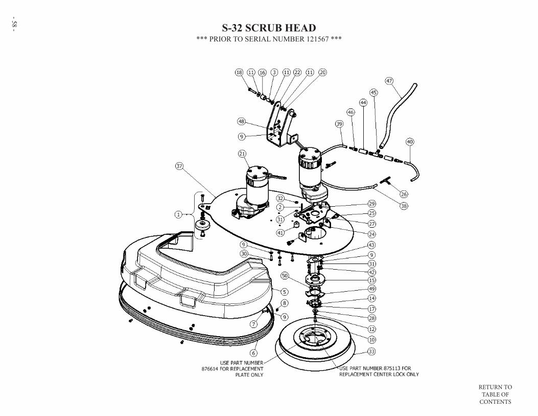
RETURN TO TABLE OF
CONTENTS
- 58 - S-32 SCRUB HEAD*** PRIOR TO SERIAL NUMBER 121567 ***
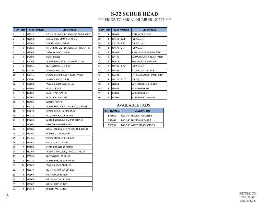
RETURN TO TABLE OF
CONTENTS
- 59 -
ITEM QTY PART NUMBER DESCRIPTION
1 1 855022 KIT GUIDE WHEEL RELACEMENT ANTI-RATTLE
2 2 915008 KEY, SQUARE, 5MM X 5 X 40MM
3 2 858203 SPACER, WHEEL, GUIDE
4 1 875021 KIT SHROUD S32 REPLACEMENT (ITEMS 4 - 8)
5 1 872306 SHROUD, HEAD, 32INCH
6 1 878502 SKIRT, BRISTLE
7 4 962263 SCREW, BUTT, SOCK, .25-20X.62, SS BO
8 4 920665 NUT, NYLOCK, 1/4-20, SS
9 20 W104D WASHER, FLAT, .25
10 2 962466 SCREW, HEX, M8-1.25 X 25, SS, PATCH
11 6 W243D WASHER, FLAT, 5/16, SS
12 2 980094 WASHER, SPLIT LOCK, .31, SS
13 1 853803 GUIDE, DRIVER
14 2 853804 GUIDE, PAD, PLASTIC
15 2 854302 HUB, DRIVER, BRUSH
16 2 857501 ROLLER, PLASTIC
17 6 962274 SCREW, FLAT, SOCK, .25-20X.62, SS, PATCH
18 2 962270 SCREW, HEX, 5/16-18X1.75,SS
20 2 920012 NUT, NYLOCK, 5/16-18, ZINC
21 2 875203 MOTOR GEAR BRUSH MRP15 SERVICE
22 1 870804 BRACKET, SUPPORT, HEAD
23 1 850906 BRUSH CARBON KIT 4 PC 855204 & 875201
24 4 871101 BUSHING, FLANGE, .50IN
25 4 962465 SCREW, SHOULDER, .50 X .50
26 2 873301 FITTING, TEE, .25INCH
27 2 876604 PLATE, MOUNTING, GIMBLE
28 2 980107 WASHER, FLAT, .31ID, 1.0OD, .12THK, SS
29 4 920035 NUT, NYLOCK, .38-16, SS
30 4 962221 SCREW, HEX, .25-20 X 1.0, SS
31 12 980002 WASHER, LOCK, SPLIT, .25
32 4 920037 NUT, THIN JAM, 1/4-20, ZINC
33 2 870903 BRUSH, POLY, 16 INCH
33 2 870905 BRUSH, NYLON, 16 INCH
33 2 870907 BRUSH, GRIT, 16 INCH
33 2 875910 DRIVER, PAD, 16 INCH
ITEM QTY PART NUMBER DESCRIPTION
37 1 876603 PLATE, MTG, 32INCH
38 1 204179 - 17.2” TUBING, 1/4”
39 1 204179 - 7.0” TUBING, 1/4”
40 1 204179 - 6.5” TUBING, 1/4”
41 4 875603 BUMPER, RUBBER, WITH STUD
42 8 964448 SCREW, HEX, M6 X 16, SS, PATCH
43 2 870818 BRACKET, RETAINING, SEAL
44 2 224130 - 1.75” TUBING, 1/2”
45 1 873308 FITTING, TEE, 0.50 INCH
46 2 853301 FITTING, REDUCER, BM08, BM04
47 1 224130 - 20.0” TUBING, 1/2”
48 4 920011 NUT, NYLOCK, 1/4-20, ZINC
49 1 873802 GUIDE DRIVER RH
49 1 853803 GUIDE DRIVER LH
50 2 857009 PLUNGER BALL PRESS-IN
AVAILABLE PADSPART NUMBER DESCRIPTION
555903 PAD 16” BLACK STRIP CASE 5
555943 PAD 16” RED SCRUB CASE 5
555954 PAD 16” WHITE POLISH CASE 5
S-32 SCRUB HEAD*** PRIOR TO SERIAL NUMBER 121567 ***

RETURN TO TABLE OF
CONTENTS
- 60 - S-32 SCRUB HEAD*** AFTER SERIAL NUMBER 121567 ***

RETURN TO TABLE OF
CONTENTS
- 61 -
S-32 SCRUB HEAD*** AFTER SERIAL NUMBER 121567 ***
PART NUMBER DESCRIPTION
555903 PAD 16” BLACK STRIP CASE 5
555943 PAD 16” RED SCRUB CASE 5
555954 PAD 16” WHITE POLISH CASE 5
870905 BRUSH NYLON 16”
870907 BRUSH GRIT 16”
875910 DRIVER PAD 16”
AVAILABLE PADS
ITEM QTY PART NUMBER DESCRIPTION
32 2 853301 FITTING, REDUCER, BM08, BM04
33 2 224130 - 1.75” TUBING, 1/2”
34 1 873308 FITTING, TEE, 0.50 INCH
35 1 224130 - 20.0” TUBING, 1/2”
36 1 204179 - 7.0” TUBING, 1/4”
37 1 875021 ASSY SHROUD S32 REPLACEMENT (ITEMS 11 - 14)
38 1 850906 BRUSH CARBON KIT 4 PC 855204 & 875201
ITEM QTY PART NUMBER DESCRIPTION
1 1 876613 PLATE, MTG, 32INCH, RIGID
2 1 855022 KIT GUIDE WHEEL REPL ANTI-RATTLE
3 1 870804 BRACKET, SUPPORT, HEAD
4 20 W104D WASHER, FLAT, .25
5 4 920011 NUT, NYLOCK, 1/4-20, ZINC
6 2 962270 SCREW, HEX, 5/16-18X1.75,SS
7 6 W243D WASHER, FLAT, 5/16, SS
8 2 857501 ROLLER, PLASTIC
9 2 858203 SPACER, WHEEL, GUIDE
10 2 920012 NUT, NYLOCK, 5/16-18, ZINC
11 1 872306 SHROUD, HEAD, 32INCH
12 1 878502 SKIRT, BRISTLE
13 4 962263 SCREW, BUTT, SOCK, .25-20X.62, SS BO
14 4 920665 NUT, NYLOCK, 1/4-20, SS
15 2 962466 SCREW, HEX, M8-1.25 X 25, SS, PATCH
16 2 980094 WASHER, SPLIT LOCK, .31, SS
17 2 980107 WASHER, FLAT, .31ID, 1.0OD, .12THK, SS
18 2 853804 GUIDE, PAD, PLASTIC
19 6 962274 SCREW, FLAT, SOCK, .25-20X.62, SS, PATCH
20 1 873802 GUIDE, DRIVER, RH
21 1 853803 GUIDE, DRIVER, LH
22 2 854302 HUB, DRIVER, BRUSH
23 2 857009 PLUNGER BALL PRESS-IN
24 4 962221 SCREW, HEX, .25-20 X 1.0, SS
25 8 964448 SCREW, HEX, M6 X 16, SS, PATCH
26 8 980002 WASHER, LOCK, SPLIT, .25
27 2 915008 KEY, SQUARE, 5MM X 5 X 40MM
28 2 875203 MOTOR GEAR BRUSH MRP15 SERVICE
29 1 204179 - 17.2” TUBING, 1/4”
30 2 873301 FITTING, TEE, .25INCH
31 1 204179 - 6.5” TUBING, 1/4”

RETURN TO TABLE OF
CONTENTS
- 62 - S-28 ORBITAL SCRUB HEAD(PAGE 1 OF 2)
ITEM QTY PART NUMBER DESCRIPTION
1 1 870812 BRACKET, MTG, HEAD, ORBITAL
2 2 855022 KIT GUIDE WHEEL REPLACEMENT ANTI-RATTLE
3 1 876609 PLATE, MOUNTING, MOTOR
5 4 858203 SPACER, WHEEL, GUIDE
6 8 W243D WASHER, FLAT, 5/16, SS
7 4 964009 SCREW, SCK, FLT, M6-1 X 20, SS, PATCH
8 2 852003 CLAMP, P-SHAPED, .62 DIA
9 2 962263 SCREW, BUTT, SOCK, .25-20X.62, SS BO
10 10 920665 NUT, NYLOCK, 1/4-20, SS
11 8 851101 BUSHING, RUBBER
12 4 858205 SPACER, RUBBER
13 2 857501 ROLLER, PLASTIC
14 1 875205 MOTOR ORBITAL SERVICE
15 1 850906 BRUSH CARBON KIT 4 PC 855204 & 875201
16 4 W117D SCREW, HEX, .25-20 X 2.0, SS
17 2 962270 SCREW, HEX, 5/16-18X1.75,SS
18 1 915006 KEY, 8MM X 7MM X 28MM
19 4 980093 WASHER, WAVE, .50INCH
20 8 980104 WASHER, RUBBER
21 4 980094 WASHER, SPLIT LOCK, .31, SS
22 4 W405D NUT, .31-18, JAM, SS
23 4 920012 NUT, NYLOCK, 5/16-18, ZINC
24 1 870813 BRACKET, SUPPORT, HEAD
25 1 204179 TUBING, 1/4”
26 1 853301 FITTING, REDUCER, BM08, BM04
27 4 962221 SCREW, HEX, .25-20 X 1.0, SS
28 8 W104D WASHER, FLAT, .25
29 1 855116 LABEL PATENT ORBITAL HEAD
30 1 879005 TUBE DISTRIBUTION S-28 ORB
31 2 856802 PLUG .62 TUBE
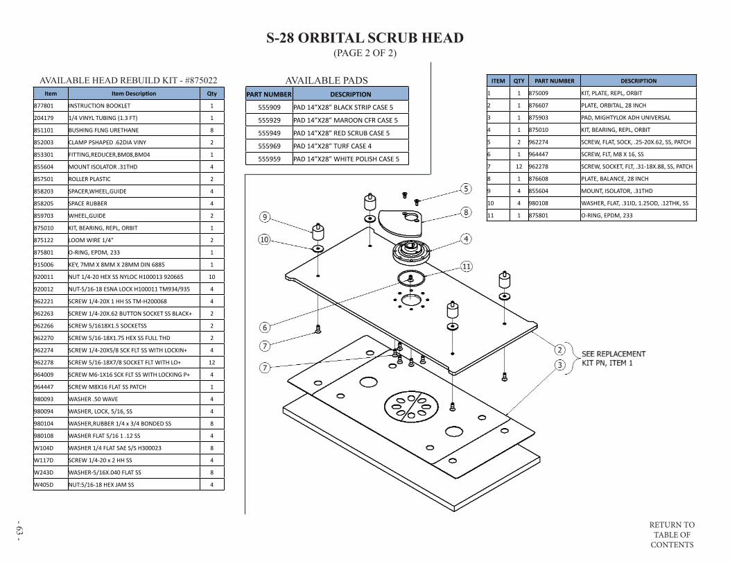
RETURN TO TABLE OF
CONTENTS
- 63 -
S-28 ORBITAL SCRUB HEAD(PAGE 2 OF 2)
ITEM QTY PART NUMBER DESCRIPTION
1 1 875009 KIT, PLATE, REPL, ORBIT
2 1 876607 PLATE, ORBITAL, 28 INCH
3 1 875903 PAD, MIGHTYLOK ADH UNIVERSAL
4 1 875010 KIT, BEARING, REPL, ORBIT
5 2 962274 SCREW, FLAT, SOCK, .25-20X.62, SS, PATCH
6 1 964447 SCREW, FLT, M8 X 16, SS
7 12 962278 SCREW, SOCKET, FLT, .31-18X.88, SS, PATCH
8 1 876608 PLATE, BALANCE, 28 INCH
9 4 855604 MOUNT, ISOLATOR, .31THD
10 4 980108 WASHER, FLAT, .31ID, 1.25OD, .12THK, SS
11 1 875801 O-RING, EPDM, 233
Item Item Description Qty
877801 INSTRUCTION BOOKLET 1
204179 1/4 VINYL TUBING (1.3 FT) 1
851101 BUSHING FLNG URETHANE 8
852003 CLAMP PSHAPED .62DIA VINY 2
853301 FITTING,REDUCER,BM08,BM04 1
855604 MOUNT ISOLATOR .31THD 4
857501 ROLLER PLASTIC 2
858203 SPACER,WHEEL,GUIDE 4
858205 SPACE RUBBER 4
859703 WHEEL,GUIDE 2
875010 KIT, BEARING, REPL, ORBIT 1
875122 LOOM WIRE 1/4” 2
875801 O-RING, EPDM, 233 1
915006 KEY, 7MM X 8MM X 28MM DIN 6885 1
920011 NUT 1/4-20 HEX SS NYLOC H100013 920665 10
920012 NUT-5/16-18 ESNA LOCK H100011 TM934/935 4
962221 SCREW 1/4-20X 1 HH SS TM-H200068 4
962263 SCREW 1/4-20X.62 BUTTON SOCKET SS BLACK+ 2
962266 SCREW 5/1618X1.5 SOCKETSS 2
962270 SCREW 5/16-18X1.75 HEX SS FULL THD 2
962274 SCREW 1/4-20X5/8 SCK FLT SS WITH LOCKIN+ 4
962278 SCREW 5/16-18X7/8 SOCKET FLT WITH LO+ 12
964009 SCREW M6-1X16 SCK FLT SS WITH LOCKING P+ 4
964447 SCREW M8X16 FLAT SS PATCH 1
980093 WASHER .50 WAVE 4
980094 WASHER, LOCK, 5/16, SS 4
980104 WASHER,RUBBER 1/4 x 3/4 BONDED SS 8
980108 WASHER FLAT 5/16 1 .12 SS 4
W104D WASHER 1/4 FLAT SAE S/S H300023 8
W117D SCREW 1/4-20 x 2 HH SS 4
W243D WASHER-5/16X.040 FLAT SS 8
W405D NUT:5/16-18 HEX JAM SS 4
AVAILABLE PADSPART NUMBER DESCRIPTION
555909 PAD 14”X28” BLACK STRIP CASE 5
555929 PAD 14”X28” MAROON CFR CASE 5
555949 PAD 14”X28” RED SCRUB CASE 5
555969 PAD 14”X28” TURF CASE 4
555959 PAD 14”X28” WHITE POLISH CASE 5
AVAILABLE HEAD REBUILD KIT - #875022

RETURN TO TABLE OF
CONTENTS
- 64 - S-24 WIRING DIAGRAM
1. If the scrub head is not working when lowered, be aware that BatteryShield® intentionally disables the scrub head when the batteries need water. Refer to the BATTERYSHIELD® AUTOMATIC WET BATTERY PROTECTION SYSTEM section of this manual.
2. For machines equipped with BatteryShield®, refer to the optional BATTERYSHIELD® sections of this diagram and the BATTERYSHIELD® AUTOMATIC WET BATTERY PROTECTION SYSTEM section prior to proceeding.
3. If a yellow LED is flashing on the battery charger, verify continuity between the charger and the battery pack. Refer to the ON-BOARD CHARGER section of this manual.
4. A circuit breaker is designed to prevent overloading a component/system. If a circuit breaker continues to trip, verify the system is not being overloaded or that a wire is not chaffed creating a short-circuit.
TROUBLESHOOTING TIPS:
Wires represented with dashed lines indicate optional equipment installation
***ALL SERIAL NUMBERS***
WIRING DIAGRAMS

RETURN TO TABLE OF
CONTENTS
- 65 -
PAGE INTENTIONALLY BLANK

RETURN TO TABLE OF
CONTENTS
- 66 - S-28 (DISK) & S-32 WIRING DIAGRAM***AFTER SERIAL NUMBER 113191***
Wires represented with dashed lines indicate optional equipment installation
TROUBLESHOOTING TIPS1. If the scrub head is not working when
lowered, be aware that BatteryShield® intentionally disables the scrub head when the batteries need water. Refer to the BATTERYSHIELD® AUTOMATIC WET BATTERY PROTECTION SYSTEM section of this manual.
2. For machines equipped with BatteryShield®, refer to the optional BATTERYSHIELD® sections of this diagram and the BATTERYSHIELD® AUTOMATIC WET BATTERY PROTECTION SYSTEM section prior to proceeding.
3. If a yellow LED is flashing on the battery charger, verify continuity between the charger and the battery pack. Refer to the ON-BOARD CHARGER section of this manual.
4. A circuit breaker is designed to prevent overloading a component/system. If a circuit breaker continues to trip, verify the system is not being overloaded or that a wire is not chaffed creating a short-circuit.
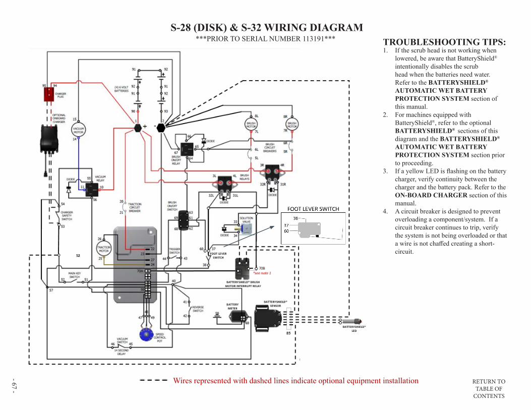
RETURN TO TABLE OF
CONTENTS
- 67 -
S-28 (DISK) & S-32 WIRING DIAGRAM
Wires represented with dashed lines indicate optional equipment installation
1. If the scrub head is not working when lowered, be aware that BatteryShield® intentionally disables the scrub head when the batteries need water. Refer to the BATTERYSHIELD® AUTOMATIC WET BATTERY PROTECTION SYSTEM section of this manual.
2. For machines equipped with BatteryShield®, refer to the optional BATTERYSHIELD® sections of this diagram and the BATTERYSHIELD® AUTOMATIC WET BATTERY PROTECTION SYSTEM section prior to proceeding.
3. If a yellow LED is flashing on the battery charger, verify continuity between the charger and the battery pack. Refer to the ON-BOARD CHARGER section of this manual.
4. A circuit breaker is designed to prevent overloading a component/system. If a circuit breaker continues to trip, verify the system is not being overloaded or that a wire is not chaffed creating a short-circuit.
TROUBLESHOOTING TIPS:***PRIOR TO SERIAL NUMBER 113191***

RETURN TO TABLE OF
CONTENTS
- 68 - S-28 ORBITAL WIRING DIAGRAM***PRIOR TO SERIAL NUMBER 113191***
Wires represented with dashed lines indicate optional equipment installation
TROUBLESHOOTING TIPS1. If the scrub head is not working when
lowered, be aware that BatteryShield® intentionally disables the scrub head when the batteries need water. Refer to the BATTERYSHIELD® AUTOMATIC WET BATTERY PROTECTION SYSTEM section of this manual.
2. For machines equipped with BatteryShield®, refer to the optional BATTERYSHIELD® sections of this diagram and the BATTERYSHIELD® AUTOMATIC WET BATTERY PROTECTION SYSTEM section prior to proceeding.
3. If a yellow LED is flashing on the battery charger, verify continuity between the charger and the battery pack. Refer to the ON-BOARD CHARGER section of this manual.
4. A circuit breaker is designed to prevent overloading a component/system. If a circuit breaker continues to trip, verify the system is not being overloaded or that a wire is not chaffed creating a short-circuit.
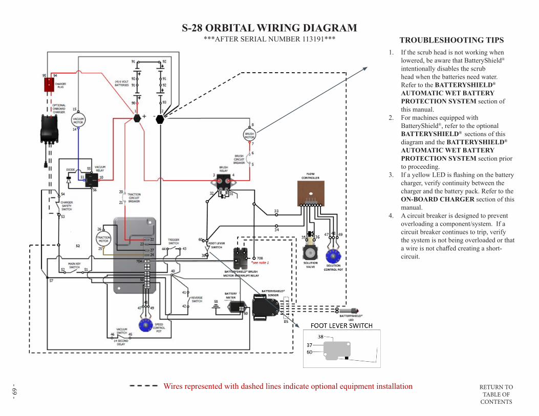
RETURN TO TABLE OF
CONTENTS
- 69 -
Wires represented with dashed lines indicate optional equipment installation
S-28 ORBITAL WIRING DIAGRAM***AFTER SERIAL NUMBER 113191*** TROUBLESHOOTING TIPS
1. If the scrub head is not working when lowered, be aware that BatteryShield® intentionally disables the scrub head when the batteries need water. Refer to the BATTERYSHIELD® AUTOMATIC WET BATTERY PROTECTION SYSTEM section of this manual.
2. For machines equipped with BatteryShield®, refer to the optional BATTERYSHIELD® sections of this diagram and the BATTERYSHIELD® AUTOMATIC WET BATTERY PROTECTION SYSTEM section prior to proceeding.
3. If a yellow LED is flashing on the battery charger, verify continuity between the charger and the battery pack. Refer to the ON-BOARD CHARGER section of this manual.
4. A circuit breaker is designed to prevent overloading a component/system. If a circuit breaker continues to trip, verify the system is not being overloaded or that a wire is not chaffed creating a short-circuit.

RETURN TO TABLE OF
CONTENTS
- 70 - BATTERYSHIELD® (OPTIONAL) WIRING DIAGRAM
BATTERYSHIELD® SENSOR IS MATED AND CALIBRATED TO THE MANIFOLD (BATT CAP) FROM THE FACTORY. SENSOR AND CAP MUST BE REPLACED AS AN ASSEMBLY – DO NOT REMOVE SENSOR FROM CAP
NOTE: BatteryShield® intentionally interrupts the scrub head circuit when the batteries need water. Refer to the BATTERYSHIELD® AUTOMATIC WET BATTERY PROTECTION SYSTEM section of this manual.

RETURN TO TABLE OF
CONTENTS
- 71 -
OPTIONAL CHEMICAL INJECTION WIRING DIAGRAM
RETURN TO TABLE OF
CONTENTS- 72 -
DATE MAINTENANCE LOG

RETURN TO TABLE OF
CONTENTS - 73 -
DATE MAINTENANCE LOG

RETURN TO TABLE OF
CONTENTS- 74 -
PAGE INTENTIONALLY BLANK
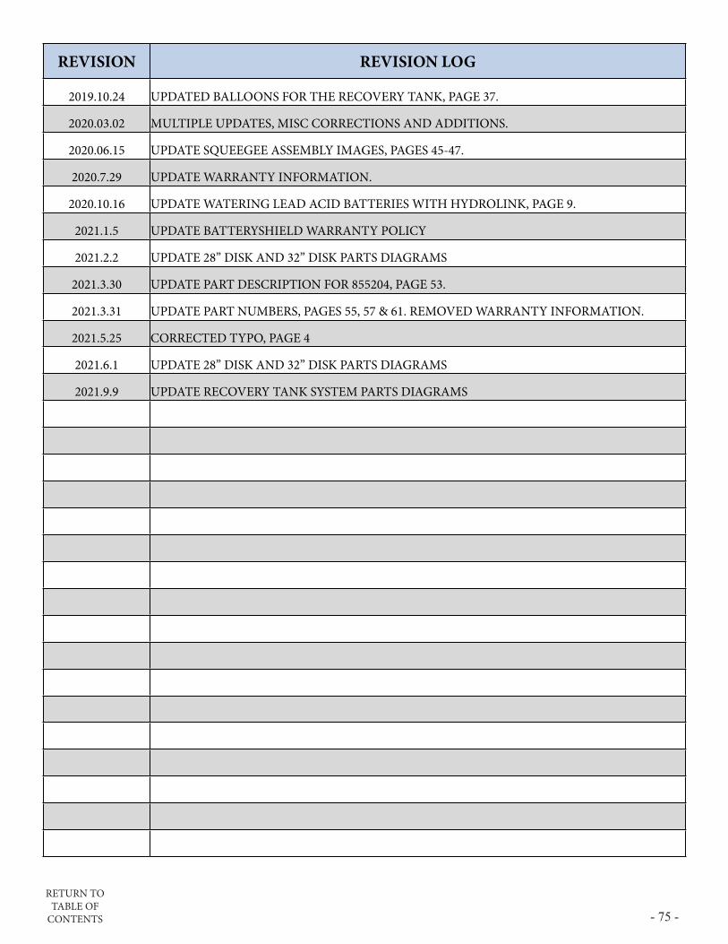
RETURN TO TABLE OF
CONTENTS - 75 -
REVISION REVISION LOG
2019.10.24 UPDATED BALLOONS FOR THE RECOVERY TANK, PAGE 37.
2020.03.02 MULTIPLE UPDATES, MISC CORRECTIONS AND ADDITIONS.
2020.06.15 UPDATE SQUEEGEE ASSEMBLY IMAGES, PAGES 45-47.
2020.7.29 UPDATE WARRANTY INFORMATION.
2020.10.16 UPDATE WATERING LEAD ACID BATTERIES WITH HYDROLINK, PAGE 9.
2021.1.5 UPDATE BATTERYSHIELD WARRANTY POLICY
2021.2.2 UPDATE 28” DISK AND 32” DISK PARTS DIAGRAMS
2021.3.30 UPDATE PART DESCRIPTION FOR 855204, PAGE 53.
2021.3.31 UPDATE PART NUMBERS, PAGES 55, 57 & 61. REMOVED WARRANTY INFORMATION.
2021.5.25 CORRECTED TYPO, PAGE 4
2021.6.1 UPDATE 28” DISK AND 32” DISK PARTS DIAGRAMS
2021.9.9 UPDATE RECOVERY TANK SYSTEM PARTS DIAGRAMS
Top Related