


Languages
Pages
Legal


400 Commonwealth Drive, Warrendale, PA 15096-0001 U.S.A. Tel: (724) 776-4841 Fax: (724) 776-5760
SAE TECHNICALPAPER SERIES
and
2002-01-2877
Testing of the Toyota Avensis DPNRat U.S. EPA-NVFEL
Joseph McDonald and Byron BunkerU.S. EPA – Office of Transportation and Air Quality
Powertrain and Fluid SystemsConference & ExpositionSan Diego, California, USA
October 21-24, 2002

All SAE papers, standards, and selectedbooks are abstracted and indexed in theGlobal Mobility Database
SAE routinely stocks printed papers for a period of three years following date of publication. Direct yourorders to SAE Customer Sales and Satisfaction Department.
Quantity reprint rates can be obtained from the Customer Sales and Satisfaction Department.
To request permission to reprint a technical papers or permission to use copyrighted SAE publications in otherworks, contact the SAE Publications Group.
Positions and opinions advanced in this paper are those of the author(s) and not necessarily those of SAE. The author issolely responsible for the content of the paper. A process is available by which discussions will be printed with the paper if itis published in SAE Transactions. For permission to publish this paper in full or in part, contact the SAE Publications Group.
Persons wishing to submit papers to be considered for presentation or publication through SAE should send the manuscriptor a 300 word abstract of a proposed manuscript to: Secretary, Engineering Meetings Board, SAE.
Printed in USA
2002-01-2877
Testing of the Toyota Avensis DPNR at U.S. EPA-NVFEL
Joseph McDonald and Byron Bunker
U.S. EPA – Office of Transportation and Air Quality
ABSTRACT
An advanced prototype of the Toyota Avensis light-duty diesel vehicle equipped with a version of Toyota’s DPNR exhaust emission control system was tested at the U.S. EPA – NVFEL facility. The vehicle is under development by Toyota Motor Corporation for introduction in Europe. While this particular model is not anticipated to be offered for sale in the U.S., EPA evaluated the vehicle to gauge the current state of light-duty diesel vehicle technology. The vehicle was tested using a low sulfur (6 ppm) diesel fuel with a cetane number that was improved to near typical European levels (~50 cetane). Emission levels over the FTP75 consistent with U.S. Federal Light-Duty Tier 2 emission standards were achieved at levels of fuel economy that are competitive with current light-duty diesel passenger vehicles offered for sale in the U.S. The vehicle was tested with relatively low accumulated mileage. Further testing at 50,000-120,000 accumulated miles will be necessary to determine the long-term durability of the emission control system.
INTRODUCTION
The Office of Transportation and Air Quality (OTAQ) of the U.S. Environmental Protection Agency (U.S. EPA) is currently evaluating progress in the development and application of NOx exhaust emission control systems for heavy-duty diesel trucks, buses, and light-duty diesel vehicles. This evaluation will gauge progress towards meeting new U.S. Federal Heavy-duty Engine emissions standards for heavy-duty buses and trucks that will phase-in beginning with model year 2007. It will also provide information to EPA on progress being made to introduce clean, fuel-efficient diesel technology that can be certified to meet the new U.S. Federal Light-duty Tier 2 emission standards that will phase-in for passenger vehicles between the 2004 and 2007 model years. This report summarizes testing conducted on a mid-size light-duty diesel passenger vehicle incorporating recently developed technology to control NOx and PM emissions to very low levels. The vehicle was provided by Toyota Motor Corporation. The Toyota Avensis Diesel is currently under development for the European market with a target of having lower emissions than the European Stage IV emission levels.
This vehicle is not intended for sale in the U.S., and has not been specifically developed to meet current or future U.S. vehicle emission standards.
TEST PROCEDURES
VEHICLE DESCRIPTION
The vehicle tested was a new version of the Toyota Avensis mid-size light-duty passenger vehicle marketed by Toyota in Europe. Major vehicle specifications are summarized in Table 1. The vehicle is equipped with a turbocharged, direct-injection diesel engine. The new Toyota Avensis diesel engine uses an electronically controlled high-pressure common-rail fuel system, high-pressure-loop electronically controlled EGR, and an electronically controlled intake throttle. Under some light-load conditions, the engine operates using a smokeless low-temperature combustion mode developed by Toyota Motor Corporation1. The Toyota Avensis was also equipped with Toyota’s Diesel Particulate – NOx Reduction (DPNR) system2. This system incorporates a NOx adsorber catalyst and a catalyzed diesel particulate filter within a single catalyzed wall-flow monolith. Toyota has previously demonstrated NOx and PM emissions reductions of greater than 80% for this type of exhaust emission control system. The vehicle was also equipped with a diesel oxidation catalyst (DOC) for additional control of hydrocarbon and CO emissions.
The vehicle provided by Toyota was a pre-production engineering prototype with relatively low accumulated mileage. As such, emissions performance should be considered to be for a relatively unaged catalyst and emission control system. The vehicle tested is similar to the 60 vehicles that will participate in an 18-month monitoring program in Europe during 2002-20033.

TEST FUEL Table 1: Summary of major vehicle specifications.
Manufacturer/Model: Prototype Toyota Avensis DPNR
Vehicle Type: Small station wagon Interior Passenger and Cargo Volume:
3.62 m3
Power Transmission: Front-drive, 5-speed manual transmission
Engine: 2.0 L, 4-cyl. Turbocharged, charge-air-cooled DI Diesel w/DOHC and 4 valves/cyl.
Power/Torque Rating: 81 kW @ 4000 rpm 250 Nm @ 2000 rpm
Fuel System: Denso HPCR Emission Control Systems: DPNR system, cooled EGR, Catalyst Volume: DPNR: 2.8 L
DOC: 2.0 L Inertia Weight (as tested): 1590 kg
The fuel used for all testing was Phillips Chemical Company Lot 1APULD02. This fuel was similar to that specified by the U.S. Department of Energy’s Diesel Emission Control-Sulfur Effects (DECSE) program to have properties comparable to today’s on-highway fuel with the exception of very low sulfur content. The engine was originally calibrated for use with diesel fuels available in Western Europe. Approximately 0.1% by mass of a common cetane additive (Ethyl Corporation, HiTEC 4103 Cetane Improver) was added to the fuel. The cetane additive (chiefly 2-ethylhexyl nitrate) was added to raise cetane number from 43 to 50 in order to provide compression ignition properties closer to that of fuels for which the engine was originally calibrated. The properties of the fuel used are summarized in Table 2.
TEST CYCLES
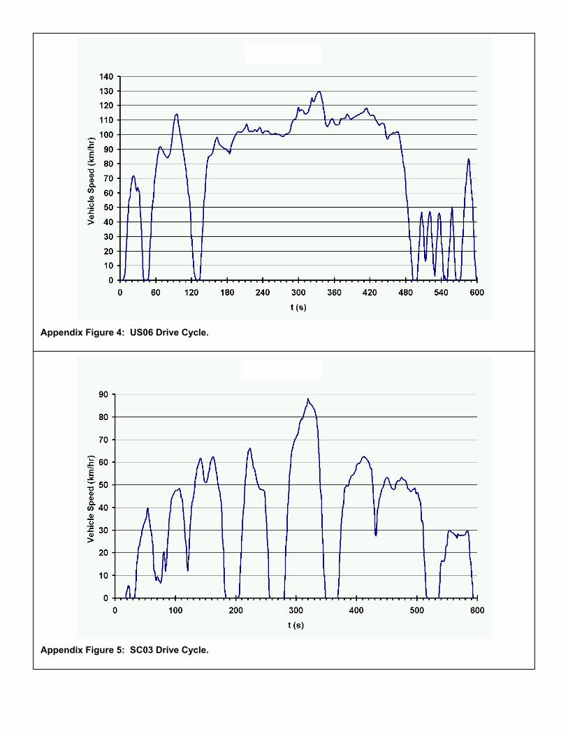
Examples of the driving traces used for chassis dynamometer testing are presented in the appendix. The vehicle was tested using the full range of chassis dynamometer test cycles required for Tier 2 certification. This included the FTP75, US06, SC03, and highway fuel economy driving cycles. The environmental conditions of the SCO3 test were simulated using a modified version of the AC2 test procedure4. The modifications to the AC2 procedure included operation at ambient conditions of 35 ºC ± 1 ºC with the vehicle windows down and the air-conditioner at its lowest temperature setting. The vehicle was also tested using the New York City Cycle to simulate operation in heavily congested urban areas.
FACILIITIES
Testing was conducted at the U.S. EPA National Vehicle and Fuel Emission Laboratory (NVFEL) in Ann Arbor, MI USA. The vehicle was tested using a 48”-diameter single-roll, electric chassis dynamometer. A summary of track and dynamometer coast-down data, including the derived dynamometer coefficients, is included in the Appendix. Vehicle exhaust was diluted using a full-flow, low-particle-loss dilution system developed by EPA. A description of the features of this system is included in the appendix. A PHILCO CFV-CVS was used for flow
Table 2: Summary of fuel properties.
Test Method Results Net Heat of Combustion, ASTM D3338-92 (MJ/kg) 43.11
Density @ 15.5 ºC (g/cm3) 0.891 Cetane Number 50.2 Cetane Index 51.7 Olefins, FIA D1319-93 (% Vol.) 2.7 Aromatics, D1319-93 (% Vol.) 27.5 Sulfur, ASTM D2622 (ppm mass) 9 Carbon, ASTM D3343-95 (% mass) 0.8654 Distillation Properties, ASTM D86
IBP (ºC): 189 10 % (ºC): 218 50 % (ºC): 260 90 % (ºC): 316
End Point (ºC): 347 Residue Diesel (%): 1.0
Recovery: 99.9% Note: Fuel additive (2-ethyl-hexyl-nitrate) used to raise cetane number from ~43 to ~50.
control of the dilute exhaust, and was operated at a nominal flow-rate of 750 scfm. Table 3 contains a summary of the exhaust gas analytical equipment used. Table 3: Exhaust gas analyzers.
Bag-sample Dilute Gas Analyzers Species
Horiba AIA-23 NDIR CO Horiba AIA-23 NDIR CO2 Beckman 400 FID Beckman 951A CLD NOx Continuos Dilute Gas Analyzers Horiba FIA-220 HFID THC Rosemount 955 HCLD NOx

RESULTS
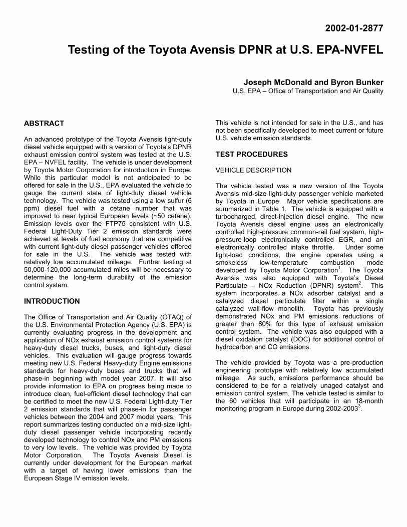
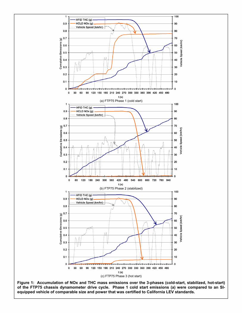
Emissions and fuel economy results are summarized in Table 4. PM emissions over the FTP75 drive cycle were at approximately one-half of the Tier 2 standards for certification bins 2 through 6. The NOx and NMHC emissions were at or just under the Tier 2 bin 5 50,000 mile FTP emission standards. Approximately 75% of the emissions during phase-1 of the FTP75 were from the second of the five accelerations following the cold-start (figure 1). Immediately after the second acceleration, minimal additional NOx was accumulated over phase-1. NOx emissions over phase-2 of the FTP75 were essentially zero. During phase-3 of the FTP75, the accumulated mass of NOx emissions was only ~10% of the mass accumulated over phase-1. As with phase-1, a majority of the NOx emissions accumulated over phase-3 of the FTP75 were associated with the second acceleration following the hot-start. NOx accumulated as a series of “break-through” events that occurred primarily over the first half of the US06 (figure 2). NOx emissions were at or below background levels over the SC03, HWFET, and NYCC drive cycles.
Table 4: Summary of exhaust emission and fuel economy results
Test Cycle
PM (mg/mi)
NOx (g/mi)
NMHC (g/mi)
CO (g/mi)
CO2 (g/mi)
FE (mi/gal)
Tier 2 bin 5
10 0.05 0.075 3.4
Tier 2 bin 6
10 0.08 0.075 3.4
FTP75 5.7 (± 0.8)
0.05 (± 0.01)
0.07 (± 0.03)
0 273 (± 2)
37.2 (± 0.2)
US06 5 (± 3)
0.14 (±.0.04)
0.19 (± 0.07)
0 289 (± 7)
35.2 (±0.8)
SC03 7 (±2)
0 0.14 (± 0.09)
0 367 (± 3)
27.7 (± 0.3)
HWFET 2 (± 1)
0 0.12 (±0.07)
0 192 (± 2)
52.9 (0.7)
NYCC 7 (±2)
0 0.04 (± 0.01)
0 474 (±10)
21.5 (± 0.5)
Notes: 50,000 mile Tier 2 bin 5 and bin 6 emission standards shown for comparison purposes. A summary of Tier 2 standards can be found in Appendix Table 1. The “±” values represent 95% confidence intervals for a two-sided students’ t-test with 3 to 4 FTP75, US06,SC03, and HWFET replicates; and 6 NYCC replicates. Bag-sampled results are shown for NOx, CO, and CO2. NMHC was derived from integrated-continuous heated-FID measurements and bag-sampled CH4. Fuel economy results are reported here as unadjusted test results.
NMHC emissions were roughly comparable over phase-1 and phase-3 of the FTP75 test. Emission levels of NMHC for the hot-stabilized (phase 2) portion of the FTP were approximately half that of phases 1 and 3. Hydrocarbon mass-emissions appeared to accumulate at near-constant rates over each phase of the FTP75 (figure 1) and over the over the US06 (figure 2), SC03, and HWFET drive cycles. It is possible that NMHC-control with this vehicle would benefit from additional oxidation catalyst volume or activity. The measured mass emissions from the continuous heated FID measurement had coefficients of variance of approximately 20 to 50% over the range of drive cycles. This was likely due to the very low level of measured NMHC emission. Additional testing using more sensitive HFID instrumentation would be necessary to draw further conclusions with respect to NMHC emissions from this vehicle at such low emission levels.
NOx and HC emissions from the Toyota Avensis DPNR over phase-1 of the FTP75 test are compared to those of a similar gasoline vehicle certified to California LEV-I LEV standards in figure 3. Stabile control of NOx emissions occurred later for the Toyota Avensis DPNR, indicating a somewhat longer period prior to NOx storage and/or light-off compared to the time to light-off for a conventional 3-way LEV catalyst system. NOx emissions, however, were considerably less for the Toyota Avensis DPNR in the period prior to achieving the NOx light-off temperature, which would indicate lower engine-out NOx emissions than the gasoline LEV vehicle immediately following the cold-start or some low temperature NOx storage depending on the engine-out level of NO2 present in the exhaust at such relatively low exhaust temperatures.
The Toyota Avensis DPNR demonstrated improved fuel economy when compared to the highest fuel economy conventional gasoline vehicles sold in the U.S. for the 2002 model year (table 6). Fuel economy was less than the highest fuel economy diesel vehicle currently offered for sale in the U.S., the 2002 VW Jetta Wagon. It should be noted that the VW Jetta Wagon is a lighter vehicle. The Jetta was also certified to U.S. Federal Tier 1 diesel emission standards that represent PM and NOx emission levels that are approximately an order of magnitude higher than the levels measured from the Toyota Avensis DPNR.
Table 5: Comparison of Toyota Avensis DPNR emissions results to 4,000 mile light-duty Tier 2 SFTP emission standards
US06 SC03 NMHC+
NOX (g/mi)
CO (g/mi)
NMHC+NOX (g/mi)
CO (g/mi)
Tier 2 SFTP Standard (4k miles)
0.14 8.0 0.20 2.7
Toyota Avensis DPNR 0.33 0 0.14 0
(a) FTP75 Phase 1 (cold start)
(b) FTP75 Phase 2 (stabilized)
(c) FTP75 Phase 3 (hot start)
Figure 1: Accumulation of NOx and THC mass emissions over the 3-phases (cold-start, stabilized, hot-start)of the FTP75 chassis dynamometer drive cycle. Phase 1 cold start emissions (a) were compared to an SI-equipped vehicle of comparable size and power that was certified to California LEV standards.
Figure 2: Accumulation of NOx and THC mass emissions over the US06 high-speed chassis dynamometerdrive cycle.
Figure 3: Phase 1 cold start emissions compared to an SI-equipped vehicle of comparable size and powerand certified to California LEV standards.

C
Tov5iv6s2uabS
A
TaaeMBeDe
Table 6: Measured fuel economy of the Toyota Avensis DPNR station wagon to similar vehicles offered for sale in the U.S.
Vehicle Type Engine Transmission/ Drive City/Highway Fuel Economy
(mi/gal)
Test Weight (lbs.)
Toyota Avensis DPNR
Small Station Wagon
2.0-L 4-cyl. Turbo-Diesel with charge-air cooling
5-speed Manual/ Front-drive
33/41 3500
2002 VW Jetta Wagon
Small Station Wagon
1.9-L 4-cyl. Turbo-Diesel with charge-air cooling
5-speed Manual/ Front-drive
42/50 3375
2002 Ford Focus Station Wagon
Mid-size Station Wagon
2.0-L NA SI gasoline 5-speed Manual/ Front-drive
28/36 3125
2002 Honda Accord
Mid-size Passenger Vehicle
2.3-L NA SI gasoline 5-speed Manual/ Front-drive
26/32 3250
Notes: The 2002 VW Jetta Wagon, Ford Focus Station Wagon, and Honda Accord included in this comparison demonstrated the highest combined fuel economy for their respective vehicle classes. Fuel economy results for
Toyota Avensis include adjustments of 10% over the city cycle and 22% over the highway cycle to better suit real-world driving conditions and to allow comparison with values reported in the Fuel Economy Guide.ONCLUSION
he Toyota Avensis DPNR demonstrated emissions ver the FTP75 drive cycle that were consistent with a ehicle capable of meeting the mid- to upper-bins (bins -8) of the Tier 2 emissions standards. With moderate
mprovements in HC emissions, the Toyota Avensis ehicle would be capable of achieving Tier 2 bin 5 or bin emissions over the FTP75 using low sulfur diesel fuel imilar to fuels that will be available in the U.S. after 006 if the emission control system is relatively durable p to the statutory full useful life (120,000). Further NOx nd NMHC reductions over the US06 drive cycle should e necessary for a vehicle of this type to meet Tier 2 FTP standards.
CKNOWLEDGMENTS
he authors wish to thank the Toyota Motor Corporation nd the Toyota Technical Center for their provision of an dvanced prototype vehicle for testing by EPA, specially Dr. Kiyoshi Nakanishi, Dr. Koichiro Nakatani, r. Taro Aoyama, Mr. Tadao Shimbori and Mr. Thomas eiershmitt. The authors also would like to thank the ngineers and technicians of the Laboratory Operations ivision at the U.S. EPA-NVFEL facility in Ann Arbor, MI, specially Mr. David Bochenek and Mr. John Menter.
REFERENCES
1. S. Sasaki, T. Ito, S. Iguchi, “Rußarme fette Verbrennung mit Niedertemperatur-Oxydation in Diesel Motoren”, 9. Aachener Kolloquium Fahrzeug- und Motorentechnik 2000 (“Smoke-less Rich Combustion by Low Temperature Oxidation in Diesel Engines”, 9th Aachen Colloquium Automobile and Engine Technology 2000).
2. K. Nakatani, S. Hirota, S. Takeshima, K. Itoh, T. Tanaka, K. Dohmae, “Simultaneous PM and NOx Reduction System for Diesel Engines”, SAE Technical Paper Series, No. 2002-01-0957.
3. Press release, Toyota Motor Corporation, March 6, 2002 (Internet URL: http://global.toyota.com/ci.html)
4. U.S. Code of Federal Regulations, Part 86, Subpart B, section 86.162, 2000.
APPENDIX
Appendix Table 1: Summary of U.S. Federal Tier 2 Light-Duty Vehicle and Truck Intermediate-Life (50,000 mile) Emission Standards.
Bin Number
NOx (g/mi)
NMOG (g/mi)
CO (g/mi)
HCHO (g/mi)
10 0.4 0.125 3.4 0.015 9 0.2 0.075 3.4 0.015
The above temporary bins expire in 2006 (for LDVs and LLDTs) and 2008 (for HLDTs)
8 0.14 0.100 3.4 0.015 7 0.11 0.075 3.4 0.015 6 0.08 0.075 3.4 0.015 5 0.05 0.075 3.4 0.015

Appendix Table 2: Track coast down-data, dynamometer coast-down data, and derived dynamometer coefficients Appendix Table 2: Track coast down-data, dynamometer coast-down data, and derived dynamometer coefficients
Speed Range Speed Range (km/hr) (km/hr)
Expected Time
Expected Time (s) (s)
Actual Time Actual Time (s) (s)
Expected ForceExpected Force(N) (N)
Actual Force Actual Force (N) (N)
125-115 125-115 6.81 6.81 6.78 6.78 659 659 662 662 115-105 115-105 7.77 7.77 7.77 7.77 577 577 578 578 105-95 105-95 8.92 8.92 8.92 8.92 503 503 503 503 95-85 95-85 10.29 10.29 10.30 10.30 436 436 436 436 85-75 85-75 11.93 11.93 12.01 12.01 376 376 374 374 75-65 75-65 13.88 13.88 14.03 14.03 323 323 320 320 65-55 65-55 16.17 16.17 16.22 16.22 277 277 277 277 55-45 55-45 18.8 18.8 18.86 18.86 239 239 238 238 45-35 45-35 21.67 21.67 21.90 21.90 207 207 205 205 35-25 35-25 24.60 24.60 27.88 27.88 182 182 180 180 25-15 25-15 27.21 27.21 27.83 27.83 165 165 161 161 15-5 15-5 29.07 29.07 30.68 30.68 154 154 146 146
Inertia: 1590 kg Inertia: 1590 kg Highway Inertia: 1614 kg Highway Inertia: 1614 kg Dynamometer Coefficient Set points Dynamometer Coefficient Set points Measured Coefficients Measured Coefficients
A A (N) (N)
B B (N/km/hr) (N/km/hr)
C C (N/km/hr2) (N/km/hr
A A (N) (N)
B B (N/km/hr)(N/km/hr)
C C (N/km/hr2) (N/km/hr
61.27 61.27 -0.8526 -0.8526 0.03783 0.03783 144.31 144.31 0.0808 0.0808 0.03513 0.03513
Appendix Figure 1: Dynamometer coast-down with vehicle. Appendix Figure 1: Dynamometer coast-down with vehicle.
2) 2)

Appendix Figure 2: FTP75 Drive Cycle.
Append
ix Figure 3: Highway Fuel Economy Drive Cycle.
Append
Append
ix Figure 4: US06 Drive Cycle.
ix Figure 5: SC03 Drive Cycle.
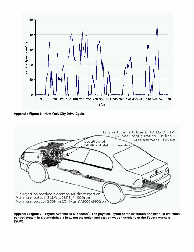
Appendix Figure 6: New York City Drive Cycle.
Appendix Figure 7: Toyota Avensis DPNR sedan3. The physical layout of the drivetrain and exhaust emission control system is distinguishable between the sedan and station wagon versions of the Toyota Avensis DPNR.
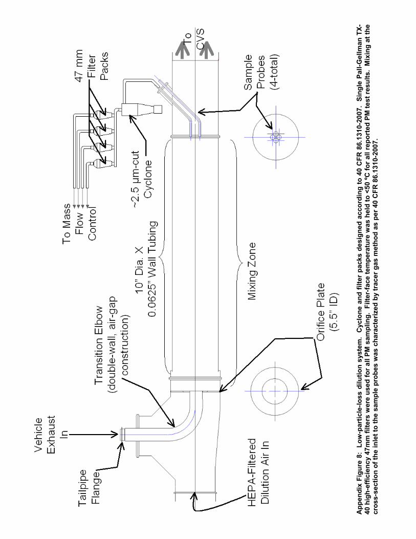
App
endi
x Fi
gure
8:
Low
-par
ticle
-loss
dilu
tion
syst
em.
Cyc
lone
and
filte
r pa
cks
desi
gned
acc
ordi
ng to
40
CFR
86.
1310
-200
7. S
ingl
e Pa
ll-G
ellm
an T
X-40
hig
h-ef
ficie
ncy
47m
m fi
lters
wer
e us
ed fo
r all
PM s
ampl
ing.
Filt
er-fa
ce te
mpe
ratu
re w
as h
eld
to <
50 ºC
for a
ll re
port
ed P
M te
st re
sults
. M
ixin
g at
the
cros
s-se
ctio
n of
the
inle
t to
the
sam
ple
prob
es w
as c
hara
cter
ized
by
trac
er g
as m
etho
d as
per
40
CFR
86.
1310
-200
7.
Top Related