


Languages
Pages
Legal

1441-1442_F19-171441-1442_F19-17 cENG 2ndCC
Non-Backlash Timing Pulleys - S8M
eFor e-Catalog non-standard products, see D P.131.
-14411 -14421
Compatible with S2M type from Mitsuboshi Belting Ltd. as well as Bando Chemical Industries Ltd.
1407 1408
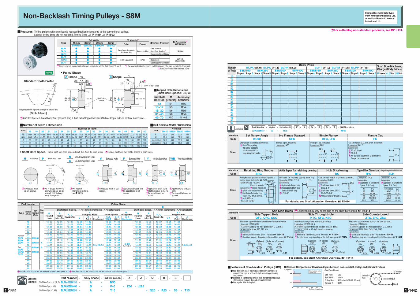
QFeatures: Timing pulleys with significantly reduced backlash compared to the conventional pulleys. Special timing belts are not required. Timing Belts W P.1499, W P.1503
TypeBelt Width M Material*1
S Surface Treatment a Accessory*1
Set Screws15mm 25mm 30mm 40mm Pulley FlangeS8M150 S8M250 S8M300 S8M400
BLPA I I I IExtra Super Duralumin
Aluminum Alloy Aluminum AlloyClear Anodize
SUS304BLPK I I I I Hard Clear Anodize*2
BLPN I I I I Electroless Nickel Plating
BLPT I I I I
S45C Equivalent SPCC-
SCM435(Black Oxide)BLPM I I I I Black Oxide
BLPP I I I I Electroless Nickel Plating
*1. The above material and accessory might be changed to the ones equivalent to the originals.*2. Hard Clear Anodize: Film Hardness 300HV ~
EFlange is already swaged, and set screws are included with for Shaft Bores P, N and C.
Part Number
PulleyShape
Pulley Shape
Type Number of Teeth
TypeNominal
Width
A BShaft Bore Specs. "~": 1mm Increments ", ": Selectable Shaft Bore Specs. "~": 1mm Increments ", ": Selectable
HRound Hole
PRound
Hole + Tap
N, CKeyway + Tap
VStepped Hole
YBoth Ends Stepped Hole
WBTwo-stepped Hole H
Round Hole
PRound
Hole + Tap
N, CKeyway + Tap
V, FStepped Hole
V ZZ-d≥2
J(0.1mm Increment)
Y(d), WB(d)
Q, RQ(R)-d≥2
S, T(0.1mm Increment) V, F Z
Z-d≥2J
(0.1mm Increment)
AluminumBLPABLPKBLPN
SteelBLPTBLPMBLPP
18
S8M150
S8M250
S8M300
S8M400
A
B
12~32 12~26 12~26 12~30 14~32
3.0≤J≤W-3.0
12~30 14~32
3~23S+T≤W-3
12~28 12~22 12~20 12~26 14~28
3.0≤J≤L-3.0
19 12~36 12~28 12~28 12~34 14~36 12~34 14~36 12~31 12~25 12~20 12~29 14~3120 12~36 12~30 12~30 12~34 14~36 12~34 14~36 12~32 12~26 12~22 12~30 14~3221 12~41 12~32 12~32 12~39 14~41 12~39 14~41 12~36 12~30 12~24 12~34 14~3622 12~41 12~34 12~34 12~39 14~41 12~39 14~41 12~37 12~30 12~25 12~35 14~3724 12~46 12~40 12~40 12~44 14~46 12~44 14~46 12~42 12~34 12~28 12~40 14~4225 12~52 12~40 12~40 12~50 14~52 12~50 14~52 12~44 12~36 12~28 12~42 14~4426 14~54 14~45 14~45 14~52 16~54 14~52 16~54 14~47 14~39 14~31 14~45 16~4728 14~56 14~48 14~48 14~54 16~56 14~54 16~56 14~51 14~43 14~35 14~49 16~5130 14~63 14~50 14~50 14~61 16~63 14~61 16~63 14~56 14~46 14~38 14~54 16~5632 14~63 14~55 14~55 14~61 16~63 14~61 16~63 14~59 14~49 14~45 14~57 16~5934 16~67 16~60 16~55 16~65 18~67 16~65 18~67 16~66 16~56 16~48 16~64 18~6636 16~72 16~65 16~55 16~70 18~72 16~70 18~72 16~71 16~61 16~50 16~69 18~7138 16~76 16~65 16~55 16~74 18~76 16~74 18~76 16~76 16~65 16~50 16~74 18~7640 20~80 20~70 20~55 20~80 22~82 20~80 22~82 20~80 20~65 20~55 20~79 22~8144 20~85 20~70 20~55 20~85 22~92 20~85 22~92 20~80 20~70 20~55 20~84 22~8648 20~85 20~70 20~55 20~85 22~95 20~85 22~95 20~85 20~70 20~55 20~85 22~9550 20~85 20~70 20~55 20~85 22~95 20~85 22~95 20~85 20~70 20~55 20~85 22~9560 20~85 20~70 20~55 20~85 22~95 20~85 22~95 20~85 20~70 20~55 20~85 22~95
XShaft Bore Dia. 51~54 are not available for Shaft Bore Specs. N. XShaft Bore Dia. 13, 14, 17 or 21~55 are not available for Shaft Bore Specs. C.
,
QNumber of Teeth / Dimension
mmNumber of Teeth
18 19 20 21 22 24 25 26 28 30 32 34 36 38 40 44 48 50 60P.D. 45.84 48.38 50.93 53.48 56.02 61.12 63.66 66.21 71.30 76.39 81.49 86.58 91.67 96.77 101.86 112.05 122.23 127.32 152.79O.D. 44.46 47.01 49.56 52.10 54.65 59.74 62.29 64.84 69.93 75.02 80.12 85.21 90.30 95.39 100.49 110.67 120.86 125.95 151.42
D 32 35 36 40 41 46 48 51 55 60 63 70 75 80 85 90 100 100 100F 52 55 58 61 61 67 70 74 80 87 87 95 99 104 111 119 127 135 160E 36 40 40 45 45 50 56 58 60 67 67 75 80 84 90 100 105 115 140
QBelt Nominal Width / Dimension
mmNominal
S8M150 S8M250 S8M300 S8M400A 17.0 28.0 33.0 44.0 W 22.0 33.0 38.0 49.0
L Number of Teeth 18~40 37.0 48.0 53.0 64.0 L Number of Teeth 44~60 42.0 53.0 58.0 69.0
EShaft Bore Specs. H (Round hole), V or F (Stepped Hole), Y (Both Sides Stepped Hole) and WB (Two-stepped Hole) do not have tapped holes.
D E
2.5
IdentificationGroove
2.5* A
F
* L
dH7
* W
E F 6.3
* A 2.52.5W/2
P.D.
O.D.
t1.6
dH7
* W
P.D.
O.D.6.3
t1.6
2-Me2-Me
8 (11 for 44 or more teeth)
Standard Tooth Profile
Tooth groove dimensions slightly vary according to the number of teeth.
(Pitch: 8.0mm)
2.83
0.68
6
dH7 Shaft Bore I.D.
M (Coarse)
Accessory: Set Screw
12 M4 M4x313~17 M5 M5x418~30 M6 M6x531~45 M8 M8x646~70 M10 M10x8
Q�Tapped Hole Dimensions (Shaft Bore Specs.: P, N, C)
• Pulley ShapeA Shape B Shape
(Counterbored Holes on the Hub Side)F Stepped HoleH Round Hole
E�No tapped holes or set screws.
P Round Hole + Tap
E�For A-Shape pulley, the screw holes are set at around 120° to keep away from peaks.
C Old JIS Keywayed Bore + Tap
N New JIS Keywayed Bore + Tap
E�For Keyway Dimension Details, see P.1413.
V Stepped Hole
E�No tapped holes or set screws.
EApplicable to Shape B only.E�No tapped holes or set
screws.
Y Both Ends Stepped Hole WB Two-stepped Hole
EApplicable to Shape A only.EShaft Bore Dia. d is +0.1 / 0E�No tapped holes or set
screws.
E�Applicable to Shape A only.
E�No tapped holes or set screws.
H7d
(120°)
H7d J±0.1
dH7
ZH7
H7d J±0.1
dH7
ZH7
S T
QH7
RH7
d+0.
1 0
H7d
(120°)
H7d J±0.1
dH7
ZH7
H7d J±0.1
dH7
ZH7
S T
QH7
RH7
d+0.
1 0
H7d
(120°)
H7d J±0.1
dH7
ZH7
H7d J±0.1
dH7
ZH7
S T
QH7
RH7
d+0.
1 0
H7d
(120°)
H7d J±0.1
dH7
ZH7
H7d J±0.1
dH7
ZH7
S T
QH7
RH7
d+0.
1 0
H7d
(120°)
H7d J±0.1
dH7
ZH7
H7d J±0.1
dH7
ZH7
S T
QH7
RH7
d+0.
1 0 dH7
S T
RH7+0.
1
Q0
• Shaft Bore Specs. Select shaft bore spec mark and each dim. from the table below. ESurface treatment may not be applied to shaft bores.
H7d
(120°)
H7d J±0.1
dH7
ZH7
H7d J±0.1
dH7
ZH7
S T
QH7
RH7
d+0.
1 0
Part Number - Pulley Shape - Shaft Bore Specs., I.D. - Z - J - Q - R - S - T(Shaft Bore Specs.: H, P, N, C) BLPA40S8M150 - A - N30(Shaft Bore Specs.: V, F) BLPK60S8M400 - B - F40 - Z60 - J25.0(Shaft Bore Specs: Y, WB) BLPA20S8M250 - A - Y15 - Q20 - R23 - S3 - T15
Number of Teeth
Body Price Shaft Bore Machining Charge (Body Price +)BLPA (x1.0) BLPK (x1.1) BLPN (x1.2) BLPT (x1.0) BLPM (x1.05) BLPP (x1.15)
S8M150 S8M250 S8M300 S8M400 S8M150 S8M250 S8M300 S8M400Shape A Shape B Shape A Shape B Shape A Shape B Shape A Shape B Shape A Shape B Shape A Shape B Shape A Shape B Shape A Shape B P Hole N, C, V, F Hole Y, WB Hole
18192021222425262830323436384044485060
QFeatures of Non-backlash Pulleys (S8M)I Non-backlash pulley has reduced backlash compared to
conventional type to work with high accuracy positioning mechanism.
I Backlash is significantly smaller than standard S8M pulleys. (The amount reduced depends on applications.)
I Use regular S8M timing belt.
Reference: Comparison of Deviation Angles between Non-Backlash Pulleys and Standard Pulleys
0 0.2 0.4 0.6 0.8 1.0 1.2
9.8
4.9
T: Load Torque N m
Deviation Angle Index
Non-Backlash PulleyStandard Pulley
DeviationAngle T: Load Torque
Ti: Tension
Fixed
Belt Type : S8MBelt Width : 25mmPulley Size : 30 Toothed (P.D.76.39mm)Tension Ti : 382N
<Test Conditions>
Part Number - Pulley Shape - Shaft Bore Specs., I.D. - Z - J - Q - R - S - T - (KC90 ••• etc.)
BLPA36S8M250 - A - H65 - NFC
AlterationsAdd Side Holes eConditions may vary depending on the shaft bore specs. D P.1414
Side Tapped Hole Side Through Hole Side CounterboredCode QTC, QFC, QSC KTC, KFC, KSC ZTC, ZFC, ZSC
Spec.
Machines tapped hole on the side surface of hub side.Ordering Code QTC28-M4
Q#C Selection Specify the hole position (P. C. D. dim.).M Selection M3, M4, M5, M6, M8Application Notes E�Minimum Thickness: 2mm Formula D P.1414E�Conditions may vary depending on the shaft bore specs. D P.1414
Machines through hole on the side surface.Ordering Code KTC28-K4.5
K#C Selection Specify the hole position (P. C. D. dim.).Code K K4.0 ~ 13.0 (0.5mm Increments)
Application Notes E�Minimum Thickness: 2mm Formula D P.1414E�Conditions may vary depending on the shaft bore specs. D P.1414
Machines counterbored hole on the side surface.Ordering Code ZTC28-Z4
Z#C Selection Specify the hole position (P. C. D. dim.).Z Selection ZM3, ZM4, ZM5, ZM6, ZM8
Application Notes E�Minimum Thickness: 2mm Formula D P.1414E�Conditions may vary depending on the shaft bore specs. D P.1414
Mx2 QSC
6-M
(6 places)QFC
4-M
(4 places)QTC
3-M
(3 places)KSC
6-K Through
(6 places)KFC
4-K Through
(4 places)KTC
3-K Through
(3 places)ZSC
6-ZM
(6 places)ZFC
4-ZM
(4 places)ZTC
3-ZM
(3 places)
Alterations Set Screw Angle No Flange Swaged Single Flange Flange CutCode KC90 NFC RFC, LFC FC
Spec.
Changes an angle of set screw to 90.EFor A-Shape pulley,
the screw holes are set at around 90° to keep away from peaks.
(Flange 2 pcs. Included)Ordering Code NFC
(Flange 1 pc. Included)Ordering Code RFC
Cut the flange O.D. in 0.5mm increment.Ordering Code FC17
Application Notes E FC≥(O. D.)+1E FC≤F-2E No surface treatment is applied on
flange circumference.
Alterations Retaining Ring Groove Adds taper for retaining bearing Hub Shortening Tapped Hole Dimensions Changes the length of the included set screws
Code SRG BTC BC TPC SLH
Spec.
Retaining Ring Groove applicable to the shaft dia. of stepped hole is machined. Retaining Ring Groove Dim. D P.1413Specify SRG 2.5~40.5mm
0.5mm IncrementsApplication Notes E�Minimum Thickness: 2mmE�Applicable to Shaft Bore Specs. V and F only.E�Standards of retaining ring
groove for Z dim. is applied.E�n≤J-SRG-m
Ordering Code SRG7
Add taper for retaining bearing inner ringOrdering Code BTC12-TL3
Application Notes EApplicable to Shape A only.E�Applicable to Shaft Bore
Specs. H and P only.ELT<L-W
Cuts the hub length in 0.5mm increment.Ordering Code BC6.5
Application Notes E�Shaft Bore Specs.H, V, F:
3≤BC<L-WE�Shaft Bore Specs.P, N, C:
M+3≤BC<L-WXNot available for Shape A.
Ordering Code TPC5Application Notes E Applicable to Shaft Bore
Specs. P, N, C only.
Ordering Code SLH10Application Notes E Applicable to Shaft Bore
Specs. P, N, C only.mn
SRG +0.1
H7Z
±0.1J
0TL
dH7
BTC
-0.1
-0.3
D RFC LFC
BC/2
BC FC F
M TPCM4 M5M5 M4, M6M6 M5, M8M8 M6, M10
M10 M8
Set Screws SLHM4x3 5, 8M5x4 6, 10M6x5 10M8x6 10, 12
M10x8 12, 15
RFC LFC
BC/2
BC FC F
QFC QTC
3-M4-M
Mx2 (4 places)QSC
6-M
(6 places) (3 places)KSC
6-K Through
(6 places)
KFC KTC
3-K Through4-K Through
(4 places) (3 places)
(90°)RFC LFC
BC/2
BC FC F
RFC LFC
BC/2
BC FC F
For details, see Shaft Alteration Overview. D P.1414
For details, see Shaft Alteration Overview. D P.1414
Top Related