


Languages
Pages
Legal


Aliaro reserve the right to vary from the description given in this data sheet and shall not be liable for any errors.
www.aliaro.com
12 Channels Multi-Function Board
AL-1010 for SLSC
This document describes the SLSC AL-1010 for National Instruments SLSC-12001 chassis.
Overview
The AL-1010 is a 12-channel multi-purpose board to be connected between the Device Under
Test (DUT) and the instrumentation part of the test system.
The board is recommended for systems requiring high flexibility on the pin configurations.
AL-1010 is made for National Instruments (NI) Switch Load Signal Conditioning (SLSC) system.
The board is made to interface with NI PXI and/or Compact-RIO instrumentation devices for the
purposes of test and validation of Electronic Control Unit (ECU) software and hardware.
Custom device for VeriStand is included for Hardware-In-the-Loop applications.
For larger applications, Aliaro Configurator is recommended for channel configuration.

Aliaro reserve the right to vary from the description given in this data sheet and shall not be liable for any errors.
www.aliaro.com
Contents
Overview.................................................................................................................................................. 1
Description .............................................................................................................................................. 4 Features ............................................................................................................................................... 4
Detailed description ............................................................................................................................ 5
Installation ............................................................................................................................................... 6 Electromagnetic Compatibility ............................................................................................................ 6
Unpacking the module ........................................................................................................................ 6
Hardware Installation .......................................................................................................................... 7
Software Installation, SLSC LabVIEW drivers....................................................................................... 8
Software Installation, Aliaro custom devices ...................................................................................... 8
Software Installation, Aliaro Configurator (Option) ............................................................................ 8
System Check ....................................................................................................................................... 8
Operation ................................................................................................................................................ 8 Safety ................................................................................................................................................... 8
Using the AL-1010 ............................................................................................................................... 8
Maintenance ........................................................................................................................................... 9 System check, using LabVIEW ............................................................................................................. 9
Calibration ........................................................................................................................................... 9
Specification .......................................................................................................................................... 10 Definition and conditions .................................................................................................................. 10
Environmental Characteristics .......................................................................................................... 10
Physical characteristics ...................................................................................................................... 10
Front connectors (J1 & J2) ................................................................................................................. 11
General specification ......................................................................................................................... 12
Fault Insertion ................................................................................................................................... 12
Signal conditioning ............................................................................................................................ 12
Digital I/O .......................................................................................................................................... 12
KADRO-AMP-4 Specification (Option) ............................................................................................... 13
KADRO-RES-2 Specification (Option) ................................................................................................. 13
Configuration and Accessories .............................................................................................................. 14 RTI Backplane .................................................................................................................................... 14
X-connector Board ............................................................................................................................. 14
KADRO-AMP-4 Amplifier Board ......................................................................................................... 14
Product Certifications and Declarations ................................................................................................ 15
CE Compliance ........................................................................................................................ 15

Aliaro reserve the right to vary from the description given in this data sheet and shall not be liable for any errors.
www.aliaro.com
Electromagnetic Compatibility Standards ......................................................................................... 15

Aliaro reserve the right to vary from the description given in this data sheet and shall not be liable for any errors.
www.aliaro.com
Description
The AL-1010 provide multiple functions for fault insertion, signal conditioning and digital I/O,
including pulsed (PWM) signals.
The AL-1010 is fitted in pair through the RTI-backplane AL-1010-RTI.
This backplane PCB is needed to reach fully flexibility and enables easy connection to NI PXIe
and/or Compact-RIO instrumentation devices.
Additional with add-on boards the functionality can be expanded further.
Features
60V, 10A per channel
12 independent and isolated channels in three banks
3 Expansion Slots for Add-on boards
Two common buses per bank with switches to each channel
Brake up switch for each channel
Programmable level threshold on each channel
Parallel connection possibility for high current signals
LabVIEW driver included

Aliaro reserve the right to vary from the description given in this data sheet and shall not be liable for any errors.
www.aliaro.com
Detailed description
Figure 1, AL-1010 Block diagram
The AL-1010 board provides fault insertion, signal conditioning and digital I/O.
Fault insertion functions:
- Open circuit (DUT to Load)
- Short to + and – (DUT to AUX 1 or AUX2)
Signal conditioning functions:
- Digital input (from DUT) signal conditioning using adjustable threshold (0-50V)
- Analogue signal (to DUT) amplification (Piggyback option)
- Analogue signal (from DUT) attenuation (fitted on DAQ connection board)
- Adjustable resistive load (from DUT) (Piggyback option)
Digital I/O functions:
- Read digital status (from DUT) using adjustable threshold
- Read PWM signals (from DUT) using adjustable threshold (Frequency and duty cycle)
- Generate digital signals (to DUT) using AUX1 (+) and AUX2 (-)
- Generate PWM signals (To DUT) using AUX1 (+) and AUX2 (-)
Aliaro reserve the right to vary from the description given in this data sheet and shall not be liable for any errors.
www.aliaro.com
Installation
Electromagnetic Compatibility
This product is intended for use in industrial locations. However, harmful interference may
occur in some installations, when the product is connected to a peripheral device or test object,
or if the product is used in residential or commercial areas. To minimize interference with radio
and television reception and prevent unacceptable performance degradation, install and use this
product in strict accordance with the instructions in the product documentation.
Furthermore, any modifications to the product not expressly approved by Aliaro
could void your authority to operate it under your local regulatory rules.
Caution To ensure the specified EMC performance, operate this product only with
Shielded cables and accessories.
Unpacking the module
• Carefully inspect the shipping container and the module for damage. Check for visible
damage
• to the exterior and interior of the damage. If damage appears to have been caused
during
• shipment file a claim with the carrier. Retain the packing material for possible inspection
• and/or reshipment. If the chassis is damaged, do not install it and contact Aliaro.

Aliaro reserve the right to vary from the description given in this data sheet and shall not be liable for any errors.
www.aliaro.com
Hardware Installation
To set up and use the module you need the following items:
Hardware
• SLSC-12001 chassis
• SLSC module(s)
• Power cable
• Power input connector
• Grounding wire
• Grounding lug
Tools
• Screwdriver as needed for your application
• Wire stripper
Documentation
SLSC-12001 Chassis Getting Started Guide and Specifications
Caution:
Do not touch the contacts or remove the I/O boards or cables while the system
is energized.
The SLSC chassis and the AL-1010 do not support hot plug-in. The entire
chassis must be powered off when a module is inserted or removed.
Procedure:
1. Power off the main DC power source or disconnect the power source from the chassis
before installing any modules or RTIs.
2. Ensure that the chassis is powered off. The POWER LED should be off. If the
POWER LED is not off, do not proceed until it is off.
3. Loosen the screws on the upper rear panel of the chassis.
4. Position the RTI backplane at the desired slot and insert the securing screws, but do not
fully tighten them.
5. Insert a AL-1010 module into the same slot as its corresponding RTI while firmly holding
the RTI in place until the RTI is firmly connected to the module.
6. Repeat steps 4 and 5 for all required RTIs.
7. Fully tighten the screws for all RTIs and the upper rear panel of the chassis. Note Waiting
until all RTIs and modules are installed to fully tighten the screws ensures proper
alignment for future connections between modules and RTIs.
8. Fully tighten the two module mounting screws on each newly installed module.
9. Power on the SLSC chassis

Aliaro reserve the right to vary from the description given in this data sheet and shall not be liable for any errors.
www.aliaro.com
Software Installation, SLSC LabVIEW drivers
When the module is used with LabVIEW or TestStand, Aliaro drivers need to be installed, see
Aliaro driver installation instruction.
Software Installation, Aliaro custom devices
When AL-1010 is used with VeriStand, Custom Devices needs to be installed, see the Custom
Device installation instruction.
Software Installation, Aliaro Configurator (Option)
Note Description of the Aliaro Configuration can be found on www.aliaro.com
System Check
Finnish the installation by conducting a system check, see chapter:
Maintenance
Operation
Safety
Caution Observe all instructions and cautions in the user documentation. Using the
model in a manner not specified can damage the model and compromise the built-in
safety protection. Return damaged models to Aliaro for repair.
Using the AL-1010
All input characteristics are DC, ACrms, or a combination unless otherwise specified. Maximum
switching voltage (any polarity) 100 Vpeak. Every card provides a fully capable fault insertion
with external control during simulations or testing. Relays can be configured with Aliaro
Configurator, VeriStand and LabVIEW
Note Steady state voltages applied to the AL-1010 between any two I/O connector pins
in excess of the maximum switching voltage specification may damage the module
Note Signal connections through the AL-1010 are intended to go through the DUTn pin
connections. Signal paths that do not use the DUTn pin connections bypass the internal
overcurrent limiting features and may exceed the module's thermal capabilities

Aliaro reserve the right to vary from the description given in this data sheet and shall not be liable for any errors.
www.aliaro.com
Maintenance
System check, using LabVIEW
This chapter requires LabVIEW development and installation of Aliaro LabVIEW drivers
To identify and control that the cards are inserted and work properly with the right firmware,
LabVIEW provides basic VI scripts to check SLSC cards mounted in chassis
1. Open LabVIEW and select “Help” in the top menu bar and press “Find Examples…”
(This opens a new window with pre-built VI (Virtual Instruments) for different
applications).
1. Switch to the “Search” tab and enter keyword “SLSC” and double click.
2. In the new filtered table (to the right) find and select VI called “Configuration.vi”. This
VI can located every card(s) that is online in SLSC chassi.
3. To find the newly inserted cards look for the SLSC chassi IP-address (in the table to
the right).
4. Count the showing card(s) in the table and make up that there are as many mounted
in the SLSC chassi as there are in the VI table for that specific IP address. (Can be 1
up to 11 cards per SLSC chassi)
Calibration
Recommended warm-up time 30 min
Calibration interval Not required, recommended on system level

Aliaro reserve the right to vary from the description given in this data sheet and shall not be liable for any errors.
www.aliaro.com
Specification
Definition and conditions
Warranted specifications describe the performance of a model under stated operating conditions
and are covered by the model warranty.
The following characteristic specifications describe values that are relevant to the use of the
model under stated operating conditions but are not covered by the model warranty.
• Typical specifications describe the performance met by a majority of models.
• Nominal specifications describe an attribute that is based on design, conformance
testing, or supplemental testing.
Specifications are Typical unless otherwise noted.
Specifications are valid under the following conditions unless otherwise noted.
The AL-1010 module is mounted in an SLSC chassis with the recommended cooling clearances
and using a power supply that meets the specifications provided in the chassis user guide. For
the entire temperature range of the chassis.
Note These specifications only apply to the product as provided by Aliaro. Modifications
to the module may invalidate these. Be certain to verify the performance of modified
modules.
Caution Observe all instructions and cautions in the user documentation. Using the
model in a manner not specified can damage the model and compromise the built-in
safety protection. Return damaged models to Aliaro for repair.
Environmental Characteristics
Temperature and Humidity
Operating temperature 0 °C to 40 °C
Storage temperature range -40 °C to 85 °C
Operating relative humidity range 10% to 90%, noncondensing
Storage relative humidity range 5% to 95%, noncondensing
Physical characteristics
Category Condition Value
Module Dimensions Excluding front handle 144.32mm x 30.48mm x 281 mm
(H x W x D)
Front Panel Connector 1 x female Weidmuller 32 high
density

Aliaro reserve the right to vary from the description given in this data sheet and shall not be liable for any errors.
www.aliaro.com
Front connectors (J1 & J2)
With 12 fully programmable pins (Analog In/Out, PWM In/Out, Digital In/Out and resistor
emulation) on the DUT connector any of the given options can be generated from Ch1 to Ch12.
The last 4 pins Ch13 to Ch16 are factory set and should not be changed. The Weidmüller
connector are chose because of their rugged and simple design and provides time saving cable
clips for the minimum use of tools, this makes them perfect for modular systems.
Caution The pins are not indestructible, ports and pins will tare if not treated with care
Channel DUT (J1) LOAD (J2)
Ch1 DUT Ch 1 Load_1
Ch2 DUT Ch 2 Load_2
Ch3 DUT Ch 3 Load_3
Ch4 DUT Ch 4 Load_4
Ch5 DUT Ch 5 Load_5
Ch6 DUT Ch 6 Load_6
Ch7 DUT Ch 7 Load_7
Ch8 DUT Ch 8 Load_8
Ch9 DUT Ch 9 Load_9
Ch10 DUT Ch 10 Load_10
Ch11 DUT Ch 11 Load_11
Ch12 DUT Ch 12 Load_12
Ch13 DUT_GND AUX1C
Ch14 ISO_GND AUX2A
Ch15 AUX1A AUX2B
Ch16 AUX1B AUX2C
Aliaro reserve the right to vary from the description given in this data sheet and shall not be liable for any errors.
www.aliaro.com
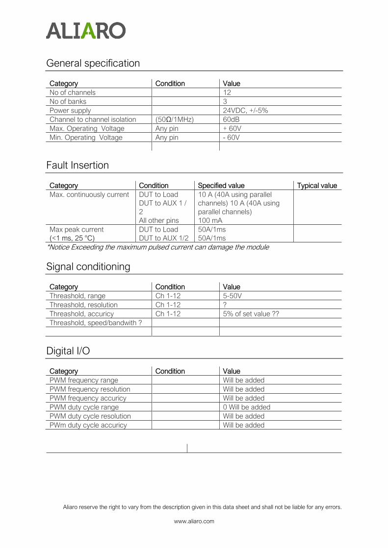
General specification
Category Condition Value
No of channels 12
No of banks 3
Power supply 24VDC, +/-5%
Channel to channel isolation (50Ω/1MHz) 60dB
Max. Operating Voltage Any pin + 60V
Min. Operating Voltage Any pin - 60V
Fault Insertion
Category Condition Specified value Typical value
Max. continuously current DUT to Load
DUT to AUX 1 /
2
All other pins
10 A (40A using parallel
channels) 10 A (40A using
parallel channels)
100 mA
Max peak current
(<1 ms, 25 °C)
DUT to Load
DUT to AUX 1/2
50A/1ms
50A/1ms
*Notice Exceeding the maximum pulsed current can damage the module
Signal conditioning
Category Condition Value
Threashold, range Ch 1-12 5-50V
Threashold, resolution Ch 1-12 ?
Threashold, accuricy Ch 1-12 5% of set value ??
Threashold, speed/bandwith ?
Digital I/O
Category Condition Value
PWM frequency range Will be added
PWM frequency resolution Will be added
PWM frequency accuricy Will be added
PWM duty cycle range 0 Will be added
PWM duty cycle resolution Will be added
PWm duty cycle accuricy Will be added

Aliaro reserve the right to vary from the description given in this data sheet and shall not be liable for any errors.
www.aliaro.com
KADRO-AMP-4 Specification (Option)
Category Condition Value
No of channels / each board 4
Power supply Need separate
Isolated supply
24VDC, +/-5%
Current drive Any pin 200mA per channel
KADRO-RES-2 Range Any pin 1 Ohm to 110 kOhm
KADRO-RES-2 Specification (Option)
Category Condition Value
No of channels / each board 4
Power supply From AL-1010 24VDC, +/-5%
Range Any pin 1 Ohm to 110 kOhm

Aliaro reserve the right to vary from the description given in this data sheet and shall not be liable for any errors.
www.aliaro.com
Configuration and Accessories
For most applications the AL-1010 needs to be configured with a backplane and a cross
connector board. The AL-1010 provides 3 expansion slots for add-on boards such as amplifier
or resistor boards, each supporting 4 channels
RTI Backplane
The AL-1010 card has three (3) expansion slots for add-on boards for adding additional
functionality for enabling more flexibility in the system.
X-connector Board
Will be added
KADRO-AMP-4 Amplifier Board
The KADRO-AMP-4 add-on board amplifies voltage and current making it possible to use
standard I/O instrumentation devices for operation. The board supplies four (4) independent
channels (bank) with amplifier functionality (enables Analogue and Digital Out).
Visit aliaro.com for more information about AL-1010 accessories. You must install mating
connectors according to local safety codes and standards and according to the specifications
provided by the manufacturer.
You are responsible for verifying the safety compliance of third-party connectors and their usage
according to the relevant standard(s).
Aliaro reserve the right to vary from the description given in this data sheet and shall not be liable for any errors.
www.aliaro.com
Product Certifications and Declarations
Refer to the product Declaration of Conformity (DoC) for additional regulatory compliance
information.
To obtain product certifications and the DoC for Aliaro products, visit aliaro.com/ certification.
CE Compliance
This product meets the essential requirements of applicable European Directives, as follows:
• 2014/35/EU; Low-Voltage Directive (safety)
• 2014/30/EU; Electromagnetic Compatibility Directive (EMC)
• 2011/65/EU; Restriction of Hazardous Substances (RoHS)
Electromagnetic Compatibility Standards
This product meets the requirements of the following EMC standards for electrical equipment for
measurement, control, and laboratory use:
• EN 55011-2009 Industrial, scientific and medical equipment - Radio-frequency
disturbance characteristics - Limits and methods of measurement CISPR 11:2009
• EN 55032:2012 Electromagnetic compatibility of multimedia equipment - Emission
requirements CISPR 32:2012
• EN 61326-1-2013 Electrical equipment for measurement, control and laboratory use -
EMC requirements - Part 1: General requirements IEC 61326-1:2012
Top Related