


Languages
Pages
Legal

Used Fuel Disposition Campaign
Swedish Task Force Ground Water Flow and Transport of Solutes (GWTFS)
Sandia National Laboratories is a multi-program laboratory managed and operated by Sandia Corporation, a wholly owned subsidiary of Lockheed Martin Corporation, for the U.S. Department of Energy’s National Nuclear Security Administration under contract DE-AC04-
94AL85000. SAND2016-nnnnn
Hari Viswanathan, Nataliia Makedonska, Satish Karra, Jeffrey Hyman Los Alamos National Laboratory Collaborators: SKB, AMPHOS, Royal Institute of Technology Stockholm 2016 UFDC Annual Working Group Meeting June 9, 2016 Las Vegas, NV
Used Fuel Disposition
2
Ground Water Flow and Transport of Solutes (GWTFS)
• The Task Force reviews all modeling work on fracture flow and solute transport made by the Äspö Hard Rock Laboratory.
• The work in the TF is tied to the experimental work performed at Äspö and/or in-
situ data from Äspö. • The work is performed within the framework of well defined and focused
Modeling Tasks. Several Modeling Teams should preferably address each Task. • The TF tries to evaluate different concepts and modeling approaches. This is
achieved by several Modeling Teams performing the same task followed by evaluation of the modeling work by the TF Delegates.
• Uncertainty quantification and rolling up the results from the different efforts were suggestions made by Stefan Finsterle and myself and in the latest Prague meeting this has now become a major focus of future work
Used Fuel Disposition
3
Task 9
Key processes:
Rock Volumes:
Scientific Areas:
Matrix diffusion in the microporous system Sorption and immobilization at mineral surfaces Reactions of solutes in the groundwater or pore water Interface between flowing and stagnant water
• The undisturbed rock matrix (REPRO, LTDE-SD) • Fracture adjacent rock surrounding flow paths (LTDE-SD)
Radionuclide transport and retention Groundwater evolution Rock/engineered barrier interface
Used Fuel Disposition
Task 9A: REPRO experiment
4
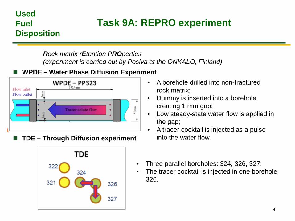
Rock matrix rEtention PROperties (experiment is carried out by Posiva at the ONKALO, Finland) WPDE – Water Phase Diffusion Experiment
TDE – Through Diffusion experiment
• A borehole drilled into non-fractured rock matrix;
• Dummy is inserted into a borehole, creating 1 mm gap;
• Low steady-state water flow is applied in the gap;
• A tracer cocktail is injected as a pulse into the water flow.
• Three parallel boreholes: 324, 326, 327; • The tracer cocktail is injected in one borehole
326.
Used Fuel Disposition
Task 9B: LTDE-SD
5
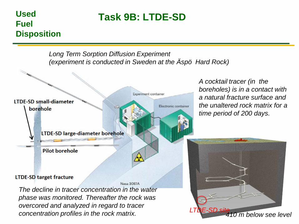
Long Term Sorption Diffusion Experiment (experiment is conducted in Sweden at the Äspö Hard Rock)
LTDE-SD site 410 m below see level
The decline in tracer concentration in the water phase was monitored. Thereafter the rock was overcored and analyzed in regard to tracer concentration profiles in the rock matrix.
A cocktail tracer (in the boreholes) is in a contact with a natural fracture surface and the unaltered rock matrix for a time period of 200 days.
Used Fuel Disposition
Task 9B: LTDE-SD
6
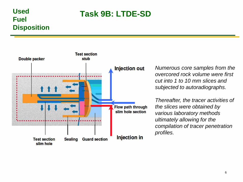
Numerous core samples from the overcored rock volume were first cut into 1 to 10 mm slices and subjected to autoradiographs. Thereafter, the tracer activities of the slices were obtained by various laboratory methods ultimately allowing for the compilation of tracer penetration profiles.
Used Fuel Disposition
Penetration Profile in LTDE
7
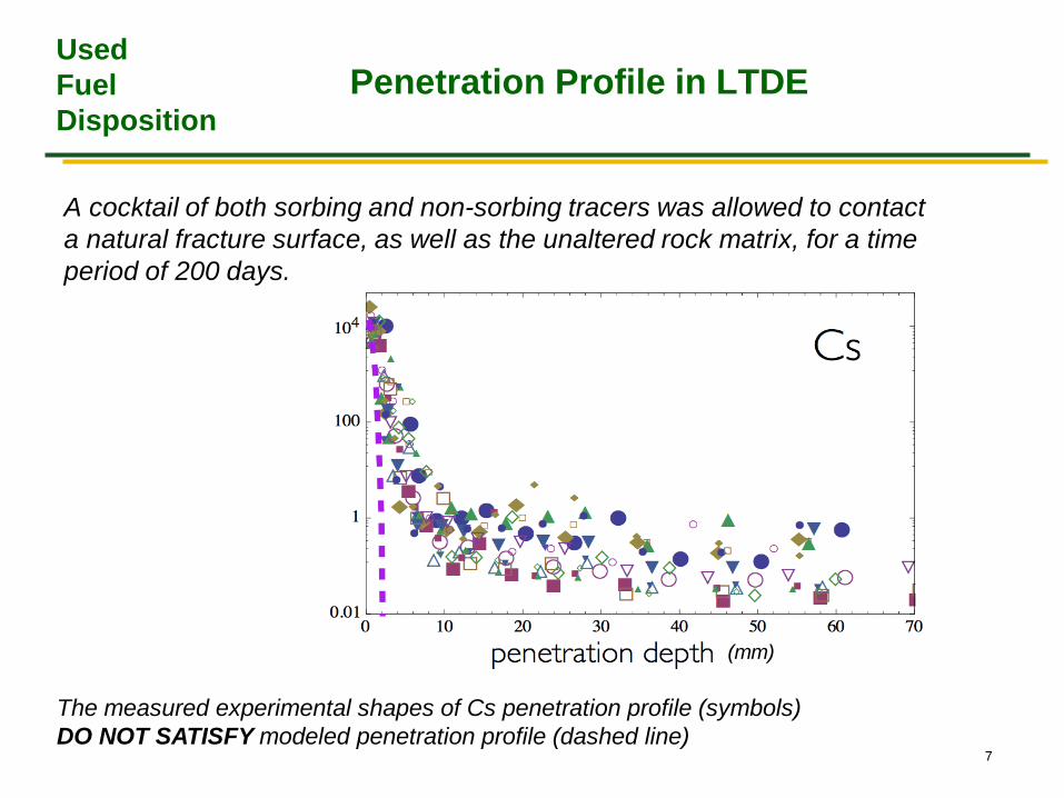
A cocktail of both sorbing and non-sorbing tracers was allowed to contact a natural fracture surface, as well as the unaltered rock matrix, for a time period of 200 days.
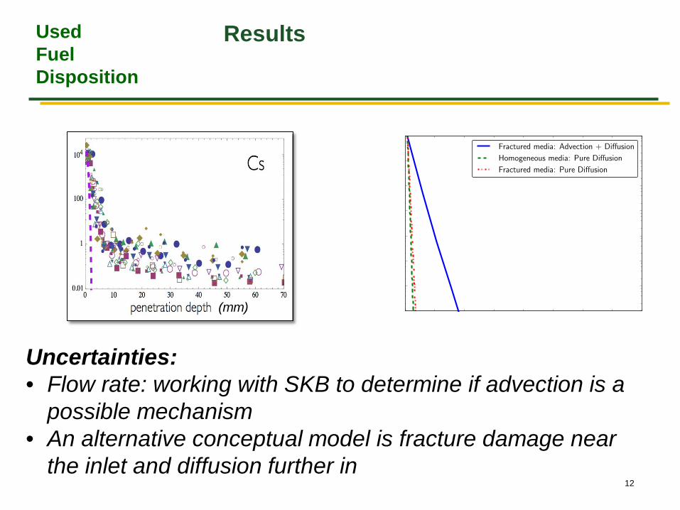
The measured experimental shapes of Cs penetration profile (symbols) DO NOT SATISFY modeled penetration profile (dashed line)
(mm)
Used Fuel Disposition
Possible Solution
8
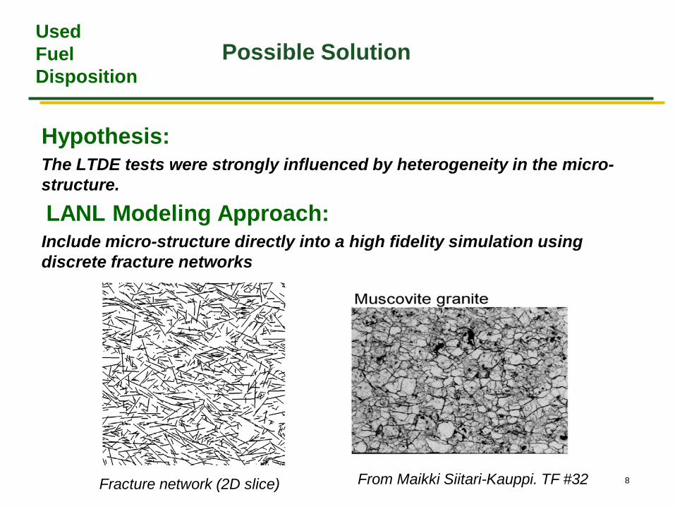
Hypothesis: The LTDE tests were strongly influenced by heterogeneity in the micro-structure.
LANL Modeling Approach: Include micro-structure directly into a high fidelity simulation using discrete fracture networks
From Maikki Siitari-Kauppi. TF #32 Fracture network (2D slice)
Used Fuel Disposition
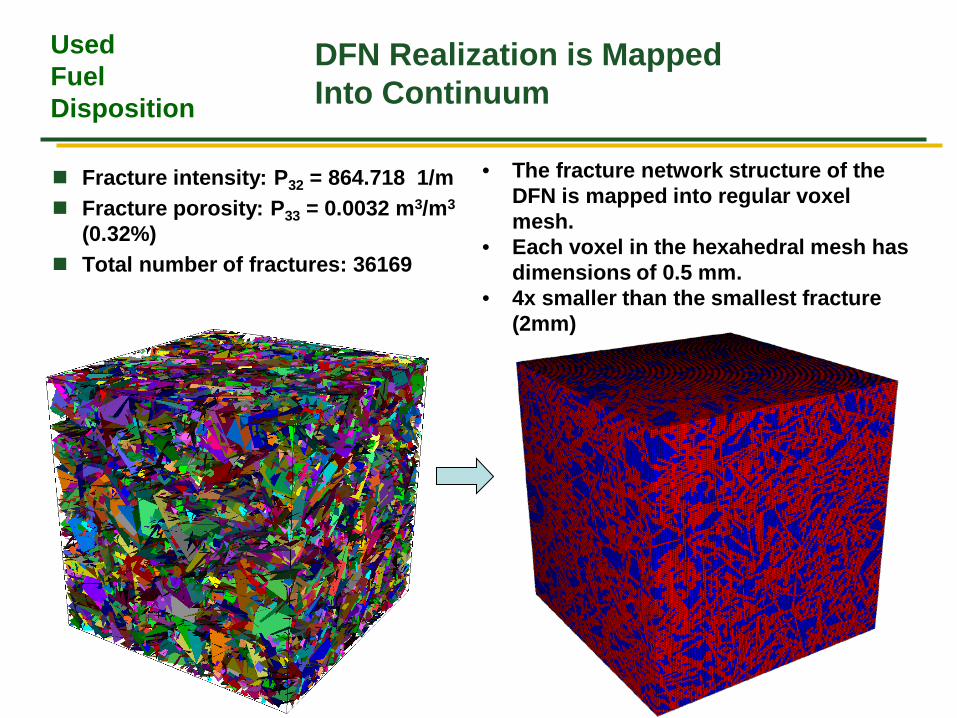
DFN Realization is Mapped Into Continuum
9
Fracture intensity: P32 = 864.718 1/m Fracture porosity: P33 = 0.0032 m3/m3
(0.32%) Total number of fractures: 36169
• The fracture network structure of the DFN is mapped into regular voxel mesh.
• Each voxel in the hexahedral mesh has dimensions of 0.5 mm.
• 4x smaller than the smallest fracture (2mm)
Used Fuel Disposition
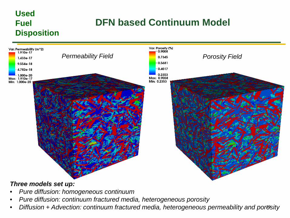
DFN based Continuum Model
10
Permeability Field Porosity Field
Three models set up: • Pure diffusion: homogeneous continuum • Pure diffusion: continuum fractured media, heterogeneous porosity • Diffusion + Advection: continuum fractured media, heterogeneous permeability and porosity
Used Fuel Disposition
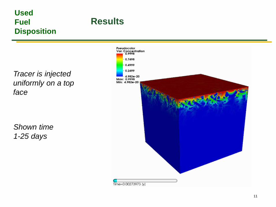
Results
11
Tracer is injected uniformly on a top face
Shown time 1-25 days
Used Fuel Disposition
Results
12
Uncertainties: • Flow rate: working with SKB to determine if advection is a
possible mechanism • An alternative conceptual model is fracture damage near
the inlet and diffusion further in
(mm)