


Languages
Pages
Legal


Dated : _______________
ASIFJAH ZEHRAVI CELL 0300 – 2568922 & 0341 – 6623062
1
Dated : _______________
ASIFJAH ZEHRAVI CELL 0300 – 2568922 & 0341 – 6623062
2
Name:_________________________________________
Class: _____________ Section:___________________
Roll No: ____________ Group:___________________

Dated : _______________
ASIFJAH ZEHRAVI CELL 0300 – 2568922 & 0341 – 6623062
3
S. No
Date
P. No
Initial
1
To determine the value of g [ acceleration due to gravity ] by using a Kater’s pendulum.
01
2
To determine the value of g [ acceleration due to gravity ] by using a compound pendulum.
05
3
To determine the modulus of rigidity of the material of a given rod by static method.
09
4
To determine the modulus of rigidity of the material of a given wire by dynamic method.
13
5
To determine the Young’s modulus of the material of a given wire by dynamic method.
17
6
To determine the coefficient of viscosity of a liquid by Stoke’s method.
22
7
To determine the distance between two points by using a sextant.
27
8
To determine the frequency of A.C supply by Meld’s method using a Vibrograph.
30
9
To prove that the photo current is directly proportional to the intensity of light falling on photocell photo cell. or Too verify the inverse square law by using a
33
10
To determine the mechanical equivalent of heat [ Value of J ] by Calander and Barne’s method.
39
11
To determine the temperature coefficient of resistance of the given wire.
43
12
To determine the thermal conductivity of non conductor by Lee’s method.
49
13
To determine the wavelength of sodium light [ D – lines ] by diffraction grating
53
14
To determine the wavelength of sodium light by Newton’s ring.
56
15
To determine the surface tension of liquid by Jeager’s method.
59
16
To determine the surface tension of liquid [ water ] by capillary rise method.
62

Dated : _______________
ASIFJAH ZEHRAVI CELL 0300 – 2568922 & 0341 – 6623062
4
LIST OF EXPERIMENTS
PRACTICAL [ I ]
To determine the value of g [ acceleration due to
gravity ] by using a compound pendulum.
To determine the value of g [ acceleration due to
gravity ] by using a Kater’s pendulum.
To determine the modulus of rigidity of the
material of a given rod by static method.
To determine the Young’s modulus of the
material of a given bar by bending of beam
method.
To determine the Young’s modulus of the
material of a given wire by dynamic method.
To determine the coefficient of viscosity of a
liquid by Stoke’s method.

Dated : _______________
ASIFJAH ZEHRAVI CELL 0300 – 2568922 & 0341 – 6623062
5
LIST OF EXPERIMENTS
PRACTICAL [ II ]
To determine the distance between two points
by using a sextant.
To determine the frequency of A.C supply by
Meld’s method using a Vibrograph.
To prove that the photo current is directly
proportional to the intensity of light falling on
photocell photo cell. Or To verify the inverse
square law by using a photo cell.
To determine the mechanical equivalent of heat
[ Value of J ] by Calander and Barne’s method.
To determine the temperature coefficient of
resistance of the given wire.
To determine the thermal conductivity of non
conductor by Lee’s method.
To determine the wavelength of sodium light
[ D – lines ] by diffraction grating
To determine the wavelength of sodium light by
Newton’s ring.
To determine the surface tension of liquid by
Jeager’s method.
To determine the surface tension of liquid
[ water ] by capillary rise method
Dated : _______________
ASIFJAH ZEHRAVI CELL 0300 – 2568922 & 0341 – 6623062
6
EXPERIMENT NO . 1
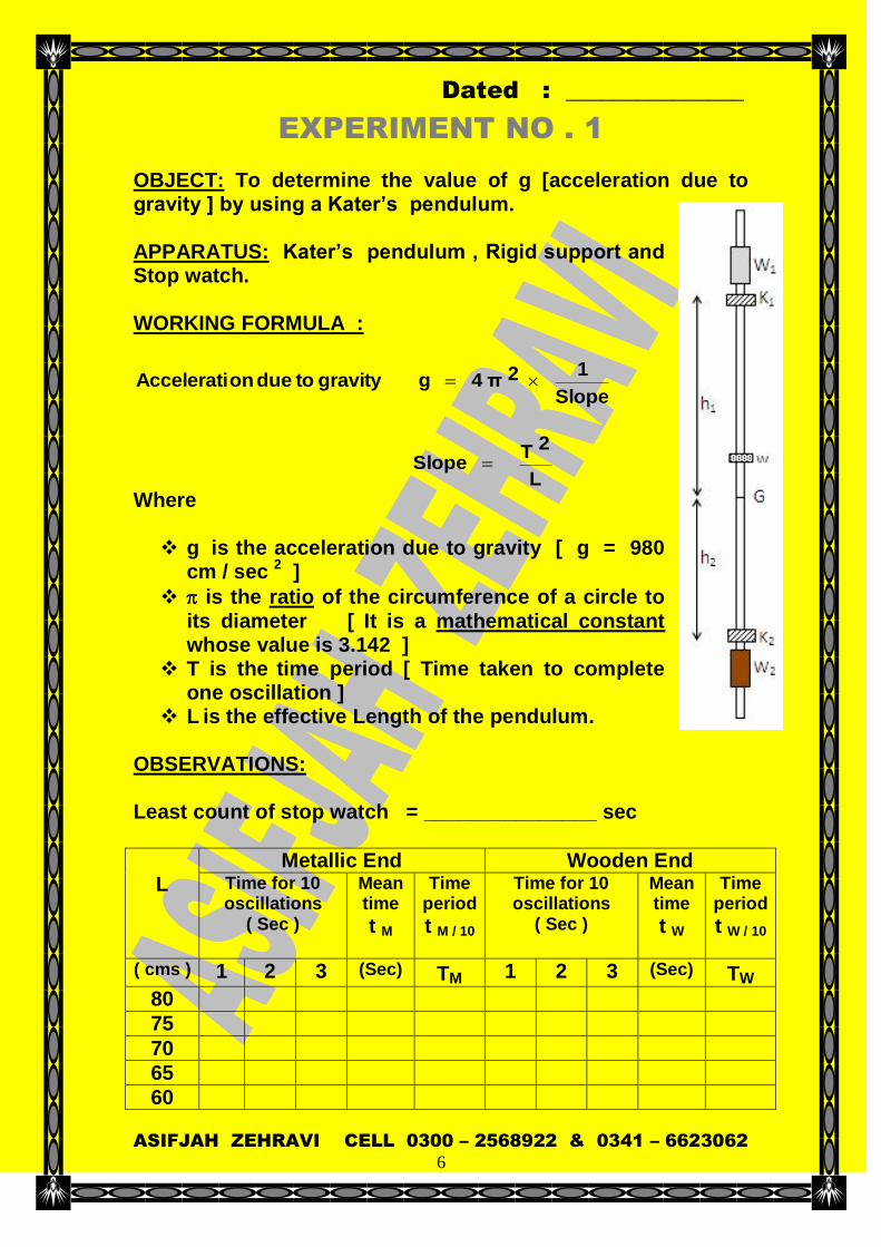
OBJECT: To determine the value of g [acceleration due to gravity ] by using a Kater’s pendulum. APPARATUS: Kater’s pendulum , Rigid support and Stop watch. WORKING FORMULA :
Slope
1 2 π 4 g gravity to due onAccelerati
L
2 T Slope
Where g is the acceleration due to gravity [ g = 980
cm / sec 2 ]
is the ratio of the circumference of a circle to its diameter [ It is a mathematical constant whose value is 3.142 ]
T is the time period [ Time taken to complete one oscillation ]
L is the effective Length of the pendulum. OBSERVATIONS: Least count of stop watch = _______________ sec
L
Metallic End Wooden End Time for 10 oscillations
( Sec )
Mean time
t M
Time period
t M / 10
Time for 10 oscillations
( Sec )
Mean time
t W
Time period
t W / 10
( cms ) 1 2 3 (Sec) TM 1 2 3 (Sec) TW
80
75
70
65
60

Dated : _______________
ASIFJAH ZEHRAVI CELL 0300 – 2568922 & 0341 – 6623062
7
55
50
45
CALC ULATIONS:
Slope
1 2 π 4 g
L
T Slope
Actual Value [ Acceleration due to gravity ]
“ g “ 980 cm / sec 2
100 ValueActual
ValueCalculated ValueActual Error Of Percentage
RESULT:
The value of g [ acceleration due to gravity ] using a Kater’s pendulum is calculated to be __________ cm / sec 2.
Percentage of error = ______ %
___________________________
Teacher’s signature PRECAUTION: Least count of slope watch should be noted and
graduation on stopwatch should be studied carefully before starting the experiment.
The support should be rigid. Least count of stopwatch should be small. The amplitude of vibration should be small (not
exceeding 1/10 th the length of pendulum). First four of five oscillations should not be counted as
motion is non linear. The time for oscillation must be noted carefully.
SOURCES OF ERROR :

Dated : _______________
ASIFJAH ZEHRAVI CELL 0300 – 2568922 & 0341 – 6623062
8
Non-linearity of the meter scale. The support of pendulum is not rigid. Inaccuracy of stopwatch. Presence of air draughts.
Dated : _______________
ASIFJAH ZEHRAVI CELL 0300 – 2568922 & 0341 – 6623062
9
EXPERIMENT NO . 2
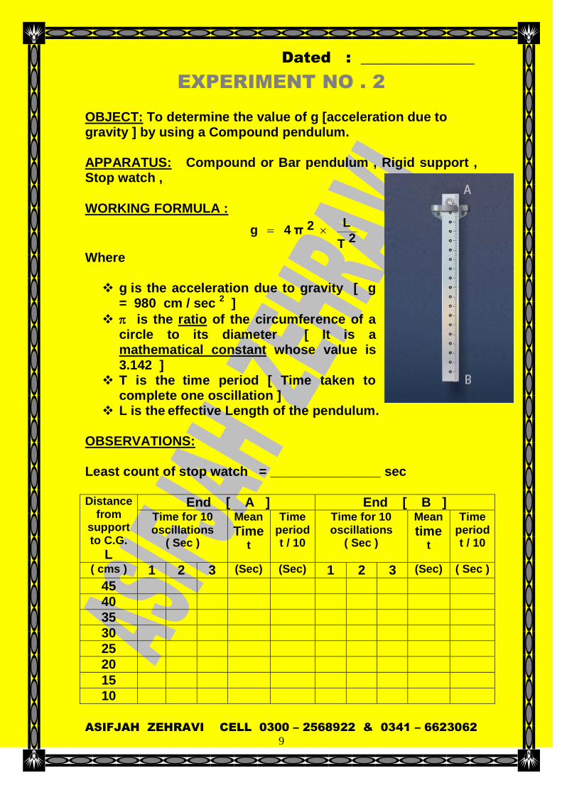
OBJECT: To determine the value of g [acceleration due to gravity ] by using a Compound pendulum. APPARATUS: Compound or Bar pendulum , Rigid support , Stop watch , WORKING FORMULA :
2 T
L 2 π 4 g
Where g is the acceleration due to gravity [ g
= 980 cm / sec 2 ]
is the ratio of the circumference of a circle to its diameter [ It is a mathematical constant whose value is 3.142 ]
T is the time period [ Time taken to complete one oscillation ]
L is the effective Length of the pendulum. OBSERVATIONS: Least count of stop watch = _______________ sec Distance
from support to C.G.
L
End [ A ] End [ B ] Time for 10 oscillations
( Sec )
Mean
Time t
Time period t / 10
Time for 10 oscillations
( Sec )
Mean
time
t
Time period t / 10
( cms ) 1 2 3 (Sec) (Sec) 1 2 3 (Sec) ( Sec )
45
40
35
30
25
20
15
10

Dated : _______________
ASIFJAH ZEHRAVI CELL 0300 – 2568922 & 0341 – 6623062
10
CALCULATIONS:
2LN KM
L Length Computed
2 T
L 2 π 4 g
Actual Value [ Acceleration due to gravity ]
“ g “ 980 cm / sec 2
100 ValueActual
ValueCalculated ValueActual Error Of Percentage
RESULT:
The value of g [ acceleration due to gravity ] using a compound pendulum is calculated to be _______cm / sec 2.
Percentage of error = ___________________ %
___________________________
Teacher’s signature

Dated : _______________
ASIFJAH ZEHRAVI CELL 0300 – 2568922 & 0341 – 6623062
11
PRECAUTION: Least count of slope watch should be noted and
graduation on stopwatch should be studied carefully before starting the experiment.
The support should be rigid. Least count of stopwatch should be small. The amplitude of vibration should be small (not
exceeding 1/10 th the length of pendulum). First four of five oscillations should not be counted as
motion is non linear. The edges K1 and K2 must be sharp.
SOURCES OF ERROR : Non-linearity of the meter scale. The support of pendulum is not rigid. Inaccuracy of stopwatch. Presence of air draughts.
Dated : _______________
ASIFJAH ZEHRAVI CELL 0300 – 2568922 & 0341 – 6623062
12
EXPERIMENT NO . 3
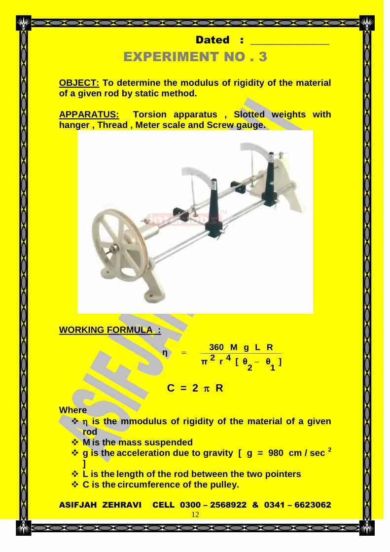
OBJECT: To determine the modulus of rigidity of the material of a given rod by static method. APPARATUS: Torsion apparatus , Slotted weights with hanger , Thread , Meter scale and Screw gauge.
WORKING FORMULA :
]1θ
2θ[ 4 r 2 π
R L g M 360 η
C = 2 R
Where
is the mmodulus of rigidity of the material of a given rod
M is the mass suspended g is the acceleration due to gravity [ g = 980 cm / sec 2
] L is the length of the rod between the two pointers C is the circumference of the pulley.
Dated : _______________
ASIFJAH ZEHRAVI CELL 0300 – 2568922 & 0341 – 6623062
13
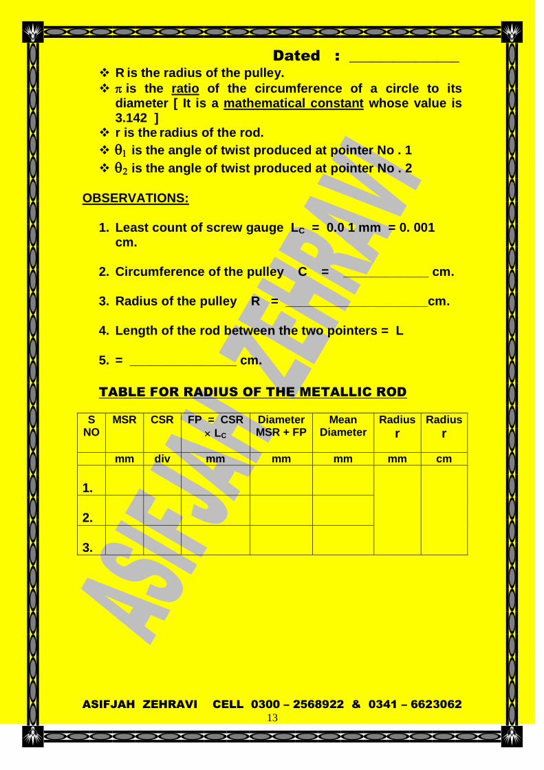
R is the radius of the pulley.
is the ratio of the circumference of a circle to its diameter [ It is a mathematical constant whose value is 3.142 ]
r is the radius of the rod.
is the angle of twist produced at pointer No . 1
is the angle of twist produced at pointer No . 2
OBSERVATIONS:
1. Least count of screw gauge LC = 0.0 1 mm = 0. 001 cm.
2. Circumference of the pulley C = ____________ cm.
3. Radius of the pulley R = ____________________cm.
4. Length of the rod between the two pointers = L
5. = _______________ cm.
TABLE FOR RADIUS OF THE METALLIC ROD
S NO
MSR
CSR
FP = CSR
LC
Diameter MSR + FP
Mean Diameter
Radius
r
Radius
r
mm div mm mm mm mm cm
1.
2.
3.

Dated : _______________
ASIFJAH ZEHRAVI CELL 0300 – 2568922 & 0341 – 6623062
14
TABLE FOR ANGLE OF TWIST
S
NO Mass
Suspended
grams
POINTER READING Mean
1
deg
Mean
2
deg
[ 2 – 1]
degrees
Twist for 500 gms deg
Load Increasing
Deg
Load Decreasing
Deg
M 1 2 1 2
1.
500
2.
1000
3.
1500
1.
2000
2.
2500
3.
3000
CALCULATIONS:
]1θ
2θ[ 4 r 2 π
R L g M 360 η
C = 2 R
Actual Value [ Modulus of rigidity of copper rod ]
“ “ 4.55 10 11 Dynes / cm 2
100 ValueActual
ValueCalculated ValueActual Error Of Percentage
RESULT: The modulus of rigidity of the material of a given rod is
calculated to be________________________ dynes / cm 2
Dated : _______________
ASIFJAH ZEHRAVI CELL 0300 – 2568922 & 0341 – 6623062
15
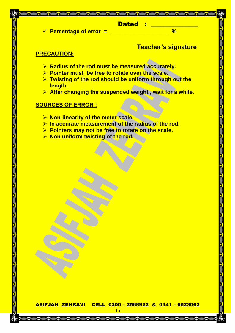
Percentage of error = ___________________ %
Teacher’s signature PRECAUTION: Radius of the rod must be measured accurately. Pointer must be free to rotate over the scale. Twisting of the rod should be uniform through out the
length. After changing the suspended weight , wait for a while.
SOURCES OF ERROR : Non-linearity of the meter scale. In accurate measurement of the radius of the rod. Pointers may not be free to rotate on the scale. Non uniform twisting of the rod.

Dated : _______________
ASIFJAH ZEHRAVI CELL 0300 – 2568922 & 0341 – 6623062
16
EXPERIMENT NO . 4
OBJECT: To determine the modulus of rigidity of the material of a given rod by dynamic method. APPARATUS: A hollow tube , Two hollow cylinders and Two solid cylinders of equal length and equal diameter , Long wire , Lamp with Scale arrangement , Stop watch , Screw gauge , Meter scale and Physical balance. WORKING FORMULA :
]2 1
T 2 2
T[ 4 r
]1
m 2
m[ L 2 l π 8 η
Where
is the modulus of rigidity of the material of a given wire
is the ratio of the circumference of a circle to its
diameter [ It is a mathematical constant whose value is 3.142 ]
l is the half length of the hollow tube. L is the length of the wire
m is the average mass of the hollow cylinders.
m 2 is the average mass of the solid cylinders.
T is the time period for 10 oscillations when the solid
cylinders are at the inner position
T 2 is the time period for 10 oscillations when the hollow
cylinders are at the inner position
r is the radius of the wire. OBSERVATIONS:
1. Least count of screw gauge LC = 0 . 0 1 m m = 0. 001 c m .
2. Total length of the hollow tube = 2 l = _____________
cms.
3. Half length of the tube = 2 l = __________________ cms.
4. Length of the wire = L = ______________________
cms.

Dated : _______________
ASIFJAH ZEHRAVI CELL 0300 – 2568922 & 0341 – 6623062
17
5. Total mass of the hollow cylinders = m T = ________
gms.
6. Average mass of the hollow cylinders m = m T /2 =___gms.
7. Total mass of the solid cylinders = m t = _________
gms
8. Total mass of the solid cylinders m 2 = m t / 2 =____gms.
9. Radius of the wire r
S NO
MSR
CSR
FP = CSR
LC
Diameter MSR + FP
Mean Diameter
Radius
r
Radius
r
mm div mm mm mm mm cm
1.
2.
3.
S NO
Time period for 10 oscillations when the solid cylinders are at the inner position
T Sec
Time period
T = t / 10
Sec
Mean
T
Sec
1
2
3
Mean
1.
2.
3.
Dated : _______________
ASIFJAH ZEHRAVI CELL 0300 – 2568922 & 0341 – 6623062
18
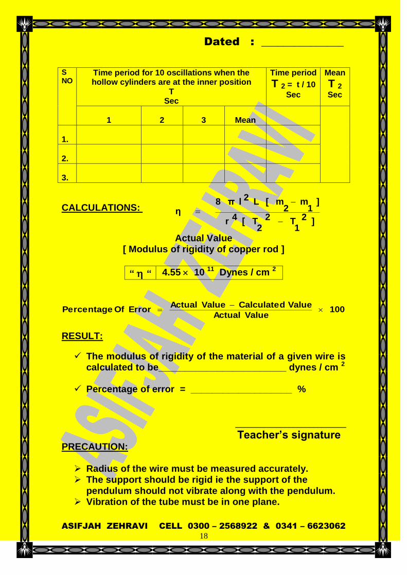
S NO
Time period for 10 oscillations when the hollow cylinders are at the inner position
T Sec
Time period
T 2 = t / 10
Sec
Mean
T 2
Sec
1
2
3
Mean
1.
2.
3.
CALCULATIONS:
]2 1
T 2 2
T[ 4 r
]1
m 2
m[ L 2 l π 8 η
Actual Value [ Modulus of rigidity of copper rod ]
“ “ 4.55 10 11 Dynes / cm 2
100 ValueActual
ValueCalculated ValueActual Error Of Percentage
RESULT:
The modulus of rigidity of the material of a given wire is calculated to be________________________ dynes / cm 2
Percentage of error = ___________________ %
___________________________
Teacher’s signature PRECAUTION: Radius of the wire must be measured accurately. The support should be rigid ie the support of the
pendulum should not vibrate along with the pendulum. Vibration of the tube must be in one plane.
Dated : _______________
ASIFJAH ZEHRAVI CELL 0300 – 2568922 & 0341 – 6623062
19
Area of the wire should be uniform through out the length.
Surface of the Maxwell’s tube must be small. Amplitude of vibration must be small. There should be no kinks in the wire.
SOURCES OF ERROR : Non-linearity of the meter scale. In accurate measurement of the radius of the rod. Kinks in the wire. Non rigid support. Non uniformity of the radius of wire.
Air drag.

Dated : _______________
ASIFJAH ZEHRAVI CELL 0300 – 2568922 & 0341 – 6623062
20
EXPERIMENT NO . 5
OBJECT: To determine the Young’s modulus of the material of a given bar by bending of beam method. APPARATUS: Given metallic bar , Meter Scale , Spherometer , Slotted weights , Vernier calipers , Cell and Connecting wire.
WORKING FORMULA :
3 d b y4
3 L g M Y
Where Y is the Young’s modulus of the material of a given bar. M is the mass suspended g is the acceleration due to gravity [ g = 980 cm / sec
2 ] L is the length of the bar between the two knife edges. y is the depression produced in the bar b is the breadth of the bar. d is the thickness of the bar.
OBSERVATIONS: Least count of screw gauge LC = 0 . 0 1 m . m = 0. 001 c ms .
S NO
MSR
CSR
FP = CSR
LC
Thickness MSR + FP
Mean Thickness
mm div mm mm mm
1.
2.
3.

Dated : _______________
ASIFJAH ZEHRAVI CELL 0300 – 2568922 & 0341 – 6623062
21
Least count of vernier calliper’s LC = 0 . 1 m . m = 0. 01 cm
S NO
MSR
VSR
FP = VSR
LC
Breadth MSR + FP
Mean Breadth
mm div mm mm mm
1.
2.
3.
S NO
Mass Sus
pended M
grams
Load Increasing
Load Decreasing
Mean Reading
y
2
]B[ A
cms
Twist for 500 gms
y cms
Mean Twist
for 500 gms
y cms
MSR cms
CSR div
FP cms
TR cms
A
MSR cms
CSR cms
FP cms
TR Cms
B
1.
50
2.
100
4.
150
5.
200
6.
250
7.
300
8.
350
CALCULATIONS:
3 d b y4
3 L g M Y
Actual Value
[ Young’s modulus of iron ]
“ “ [ 19 – 20 ] 10 11 Dynes / cm 2
[ Young’s modulus of steel ]
“ “ [ 19.5 – 20.6 ] 10 11 Dynes / cm 2
Dated : _______________
ASIFJAH ZEHRAVI CELL 0300 – 2568922 & 0341 – 6623062
22
100 ValueActual
ValueCalculated ValueActual Error Of Percentage
RESULT:
The Young’s modulus of the material of a given bar by
bending of beam method .is calculated to be___ dynes /
cm 2
Percentage of error = ___________________ %
___________________________
Teacher’s signature PRECAUTIONS: Edges on which the bar is suspended must be sharp and
rigid and must be perpendicular to the length of the bar. Load must be changed in regular steps. Load must be suspended at the centre of gravity of the
bar and it’s distance must be equal from the two knife edges.
The bar must be of uniform thickness. Thickness of the bar must be measured accurately. Positions of the sharp edges must be kept fixed through
out the experiment. SOURCES OF ERROR: Edges may not be sharp. In accurate measurement of the Breadth and thickness
of the bar. The sharp edges may not be fixed during the
experiment. Load may not be changed in a regular steps.

Dated : _______________
ASIFJAH ZEHRAVI CELL 0300 – 2568922 & 0341 – 6623062
23
EXPERIMENT NO . 6
OBJECT: To determine the coefficient of viscosity by Stoke’s method.
APPARATUS: Given liquid , Small ball bearings , Stop watch , Screw gauge , Vernier calipers , Long glass tube fitted to a wooden frame , Meter scale
WORKING FORMULA: ] R
r 4 . 2 1 [ V
0V
0 V9
] D - d [ g2r π 2 η
Where
is the coefficient of viscosity. is the ratio of the circumference of a circle to its
diameter [ It is a mathematical constant whose value is 3.142 ]
r is the radius of the spherical body g is the acceleration due to gravity [ g = 980 cm / sec 2
] d is the density of the ball bearing. D is the density of the liquid. V0 is the terminal velocity. X is the inner diameter of the glass tube. R is the inner radius of the glass tube. V is the observed Velocity
Dated : _______________
ASIFJAH ZEHRAVI CELL 0300 – 2568922 & 0341 – 6623062
24
OBSERVATIONS:
Density of the ball bearing. = d = 7. 8 gm / cm 3 Density of the given liquid = D = 1. 26 gm / cm 3
Smallest division division on main scale = a =
_____cm.
Total number of divisions on vernier scale = b =
_____cm.
Least count or Vernier constant = b
a =
____________cm. Inner diameter of the glass tube = X = 3 . 5 cm
Inner radius of glass tube = R = r = d / 2 = 3.5 / 2 = 1. 75
cm
Pitch of the screw = rotation of Number
scale main on moved Distance =_____m.
m Total number of divisions on circular scale
=_______divisions
Least count = scale circular on divisions of number Total
screw the of Pitch
Least count =______________m . m
=_____________cm. Zero error Z =______________m . m
=_____________cm.
Dated : _______________
ASIFJAH ZEHRAVI CELL 0300 – 2568922 & 0341 – 6623062
25
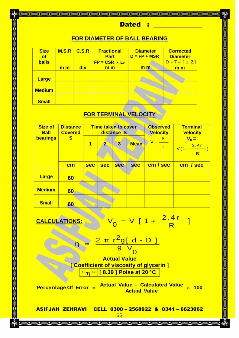
FOR DIAMETER OF BALL BEARING
Size of
balls
M.S.R
m m
C.S.R
div
Fractional Part
FP = CSR LC
m m
Diameter D = FP + MSR
m m
Corrected Diameter
] Z [T D
m m
Large
Medium
Small
FOR TERMINAL VELOCITY
Size of
Ball bearings
Distance Covered
S
Time taken to cover distance S
Observed Velocity
t
S V
Terminal velocity
V0 =
)
R
r 4 . 2 1 (V
1
2
3
Mean
cm sec sec sec sec cm / sec cm / sec
Large
60
Medium
60
Small
60
CALCULATIONS: ] R
r 4 . 2 1 [ V
0V
0 V9
] D - d [ g2r π 2 η
Actual Value [ Coefficient of viscosity of glycerin ]
“ “ [ 8.39 ] Poise at 20 C
100 ValueActual
ValueCalculated ValueActual Error Of Percentage

Dated : _______________
ASIFJAH ZEHRAVI CELL 0300 – 2568922 & 0341 – 6623062
26
RESULT: The thermal conductivity of non conductor by Lee’s
method is calculated to be ______________ cal / sec / cm
/ C
Percentage of error = ___________________ %
___________________________
Teacher’s signature PRECAUTION:
Least count of stop watch should be noted and
graduation on stopwatch should be studied carefully before starting the experiment.
The ball bearings must be released slowly from just above the liquid surface.
Temperature of the liquid should remain constant through out the experiment.
Ball bearings must be released in the middle of the tube. Liquid should be transparent and free of dust particles. Surface of the ball bearings must be free of dust and
grease. Tube must be vertical.
SOURCES OF ERROR : Inaccuracy of stopwatch. Liquid may not be pure. Change of temperature during the experiment. Surface of the balls may not be free of grease The tube may not be exactly vertical
Dated : _______________
ASIFJAH ZEHRAVI CELL 0300 – 2568922 & 0341 – 6623062
27
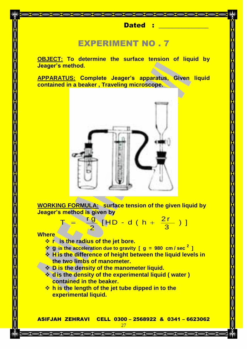
EXPERIMENT NO . 7
OBJECT: To determine the surface tension of liquid by Jeager’s method.
APPARATUS: Complete Jeager’s apparatus, Given liquid contained in a beaker , Traveling microscope.
WORKING FORMULA: surface tension of the given liquid by Jeager’s method is given by
] ) 3
r 2 h ( d - D H [
2
g r T
Where r is the radius of the jet bore. g is the acceleration due to gravity [ g = 980 cm / sec
2 ]
H is the difference of height between the liquid levels in the two limbs of manometer.
D is the density of the manometer liquid. d is the density of the experimental liquid ( water )
contained in the beaker. h is the length of the jet tube dipped in to the
experimental liquid.

Dated : _______________
ASIFJAH ZEHRAVI CELL 0300 – 2568922 & 0341 – 6623062
28
OBSERVATIONS:
Least count of traveling microscope = LC =
___________cm
S NO
Traveling microscope readings when origin of it’s cross wires
are focused on
Diameter of the jet
D = Y – X
Mean Diameter of the jet
Radius of the
jet Right edge
[ X ] Left edge
[ y ]
cm cm cm cm cm
1.
2.
3.
OBSERVATIONS:
Density of the manometer liquid [ water ] = D = 1 gm /
cm 3 Density of the experimental liquid [ water ] = d = 1 gm /
cm 3 Acceleration due to gravity = g = 980 cm / sec
2
Room temperature = T = ____________________ C
S
NO
Length of the jet tube dipped
in the liquid
h
Position of liquid column just before the detachment of an air bubble in the
Difference of height between the two liquid
levels
H = B – A
Closed limb
[ A ] Open limb
[ B ]
cm cm cm cm
1.
2.
3.
Dated : _______________
ASIFJAH ZEHRAVI CELL 0300 – 2568922 & 0341 – 6623062
29
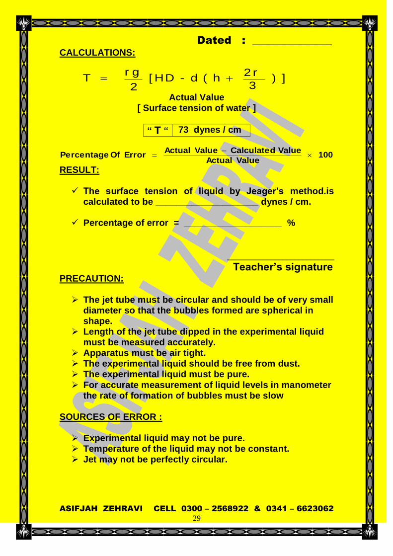
CALCULATIONS:
] ) 3
r 2 h ( d - D H [
2
g r T
Actual Value [ Surface tension of water ]
“ T “ 73 dynes / cm
100 ValueActual
ValueCalculated ValueActual Error Of Percentage
RESULT: The surface tension of liquid by Jeager’s method.is
calculated to be ____________________ dynes / cm.
Percentage of error = ___________________ %
___________________________
Teacher’s signature PRECAUTION: The jet tube must be circular and should be of very small
diameter so that the bubbles formed are spherical in shape.
Length of the jet tube dipped in the experimental liquid must be measured accurately.
Apparatus must be air tight. The experimental liquid should be free from dust. The experimental liquid must be pure. For accurate measurement of liquid levels in manometer
the rate of formation of bubbles must be slow
SOURCES OF ERROR : Experimental liquid may not be pure. Temperature of the liquid may not be constant. Jet may not be perfectly circular.
Dated : _______________
ASIFJAH ZEHRAVI CELL 0300 – 2568922 & 0341 – 6623062
30
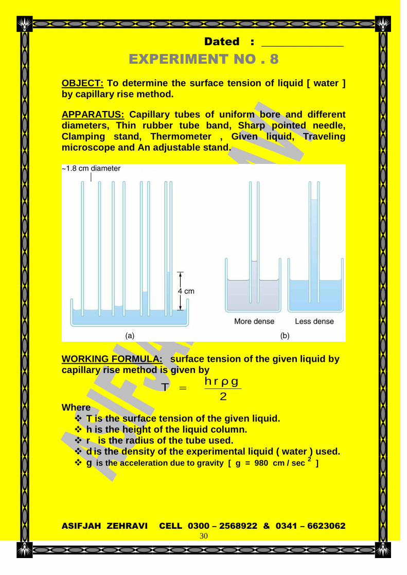
EXPERIMENT NO . 8
OBJECT: To determine the surface tension of liquid [ water ] by capillary rise method.
APPARATUS: Capillary tubes of uniform bore and different diameters, Thin rubber tube band, Sharp pointed needle, Clamping stand, Thermometer , Given liquid, Traveling microscope and An adjustable stand.
WORKING FORMULA: surface tension of the given liquid by capillary rise method is given by
2
g ρ r h T
Where T is the surface tension of the given liquid. h is the height of the liquid column. r is the radius of the tube used. d is the density of the experimental liquid ( water ) used. g is the acceleration due to gravity [ g = 980 cm / sec
2 ]
Dated : _______________
ASIFJAH ZEHRAVI CELL 0300 – 2568922 & 0341 – 6623062
31
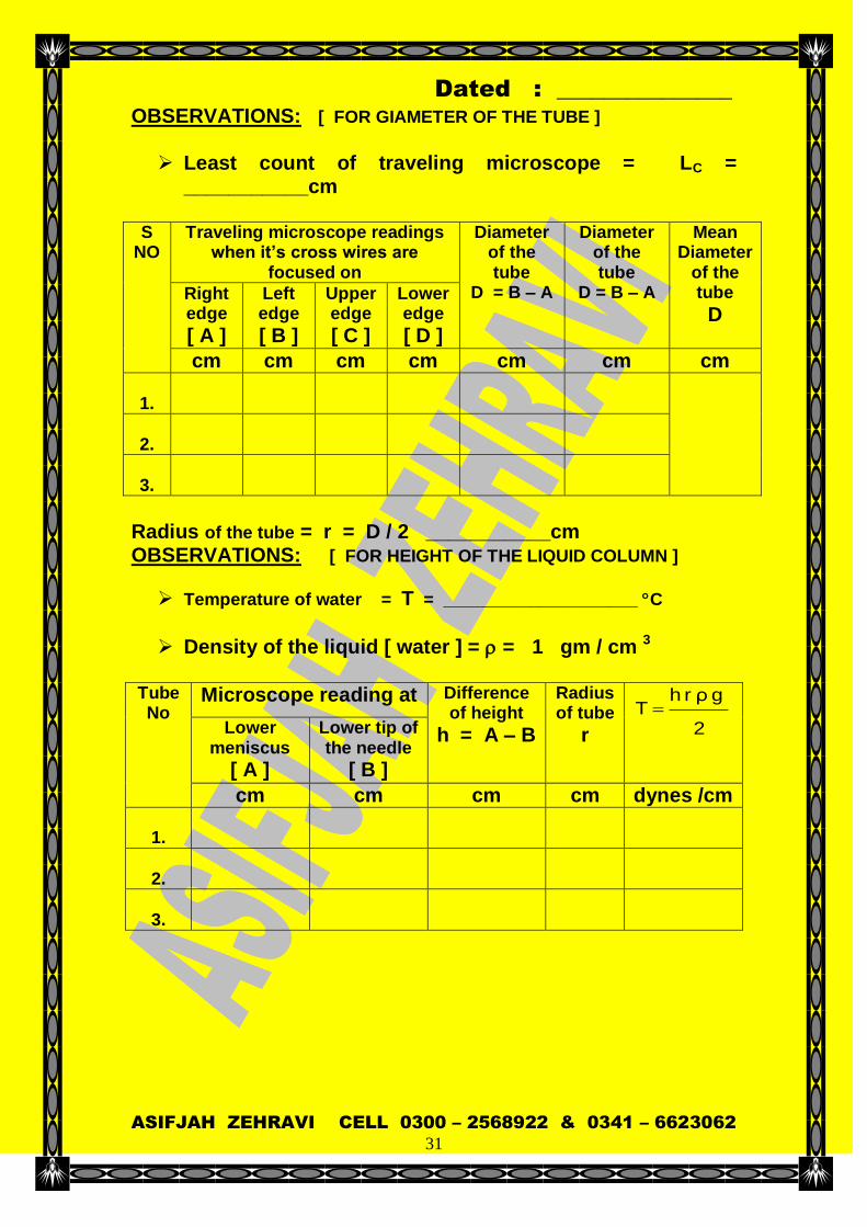
OBSERVATIONS: [ FOR GIAMETER OF THE TUBE ] Least count of traveling microscope = LC =
___________cm
S NO
Traveling microscope readings when it’s cross wires are
focused on
Diameter of the tube
D = B – A
Diameter of the tube
D = B – A
Mean Diameter
of the tube
D Right edge
[ A ]
Left edge
[ B ]
Upper edge
[ C ]
Lower edge
[ D ]
cm cm cm cm cm cm cm
1.
2.
3.
Radius of the tube = r = D / 2 ___________cm OBSERVATIONS: [ FOR HEIGHT OF THE LIQUID COLUMN ]
Temperature of water = T = ____________________ C
Density of the liquid [ water ] = = 1 gm / cm 3 Tube No
Microscope reading at Difference of height
h = A – B
Radius of tube
r
2
g ρ r h T
Lower meniscus
[ A ]
Lower tip of the needle
[ B ]
cm cm cm cm dynes /cm
1.
2.
3.

Dated : _______________
ASIFJAH ZEHRAVI CELL 0300 – 2568922 & 0341 – 6623062
32
CALCULATIONS:
2
g ρ r h T
Actual Value
[ Surface tension of water ]
“ T “ 73 dynes / cm
100 ValueActual
ValueCalculated ValueActual Error Of Percentage
RESULT: The surface tension of liquid [ water ] by capillary rise
method is calculated to be ________________ dynes / cm.
Percentage of error = ___________________ %
___________________________
Teacher’s signature PRECAUTION: The capillary tube should be of fine and uniform bore. The tube should be vertical and sufficiently apart. As for as possible use of wax for fixing the tubes should
be avoided In stead of use of a thin rubber band be preferred.
The container should be full with the water level slightly above it’s edges.
The water surface should be free from grease and hence should never be touched with fingers.
The lower tip of the needle should be just above the water surface and not dip in to it.
The tube should be cut and it’s diameter determined at the level of water meniscus.

Dated : _______________
ASIFJAH ZEHRAVI CELL 0300 – 2568922 & 0341 – 6623062
33
The diameter of the tubes should be measured in two cross wire positions.
Use of distilled water should be avoided. The experimental liquid should be free from dust. The experimental liquid must be pure.
SOURCES OF ERROR : Non uniform capillary tube may be used. Capillary tube may not be exactly vertical. Surface of water may be greasy. Diameter of the capillary tube may not be measured
accurately.
Experimental liquid may not be pure. Temperature of the liquid may not be constant.

Dated : _______________
ASIFJAH ZEHRAVI CELL 0300 – 2568922 & 0341 – 6623062
34
EXPERIMENT NO . 9
OBJECT: To determine the distance between two points by using a sextant. APPARATUS: Sextant , Meter scale and Vertical stand.
WORKING FORMULA :
β Cot - α Cot
L d
α Tan - β Tan
] β Tan α Tan [ L d OR
Where d is the distance between the two points on the wall. L is the distance through which Sextant is moved.
is the angle through which the index arm is turned to coincide the images of two the points.
is the angle through which the index arm is turned after moving the Sextant distance L to coincide the images of two the points.
.

Dated : _______________
ASIFJAH ZEHRAVI CELL 0300 – 2568922 & 0341 – 6623062
35
OBSERVATIONS: Least count of the Sextant = _______________ sec S
NO
L1 Angle
A When
AA are in
St. line
Angle B
When AB
are in St. line
Angle
=
[B – A]
L2
Angle C
When AA
are in St. line
Angle D
When AB
are in St. line
Angle
=
[D – C]
Distance
L =
[L2 – L1]
cm deg deg degrees cm cm cm degrees cm
1.
0
50
2.
50
100
3.
100
150
CALCULATIONS:
β Cot - α Cot
L d
α Tan - β Tan
] β Tan α Tan [ L d
OR
Actual Value [ Acceleration due to gravity ]
“ d “ 96 cm
100 ValueActual
ValueCalculated ValueActual Error Of Percentage
RESULT:
The distance between the two points A and B by using the
sextant is calculated to be _________________ cm.
Percentage of error = ___________________ %
___________________________
Teacher’s signature

Dated : _______________
ASIFJAH ZEHRAVI CELL 0300 – 2568922 & 0341 – 6623062
36
PRECAUTION: Least count of the sextant should be determined accurately The points A and B should be in a plane perpendicular to the
line joining the lower point A with the sextant. The lower point A must be at the level of the sextant. Sextant should be firmly fixed to the stand. The sextant should be properly leveled. Parallax between directed and reflected images should be
removed completely. The sextant should be clamped in vertical position, so that
axis of the telescope is horizontal. The telescope should be in level with the lower mark.
The two images should overlap and should have equal intensity.
Rotate the moveable arm slowly
SOURCES OF ERROR :
Parallax between direct and reflected images may not have been removed completely.
In accurate reading of the instruments. Mirrors of the sextant may not be parallel to each other

Dated : _______________
ASIFJAH ZEHRAVI CELL 0300 – 2568922 & 0341 – 6623062
37
EXPERIMENT NO . 10
OBJECT: To determine the frequency of A.C supply by Meld’s method using a Vibrograph. APPARATUS: A.C. main supply , Vibrograph with step down voltage transformer , String , Pan , Adjustable pulley , Two upright pins , Weights and meter scale. WORKING FORMULA :
μ
g M
2L
1 string of Frequency
μ
g M
2L
1
sF
2
sF Mean
supply main C . A of Frequency
Where
FS is the frequency of string. L is the distance between two consecutive nodes. [ Length
of single loop ] M is the total mass suspended. g is the acceleration due to gravity [ g = 980 cm / sec 2 ]
is the linear density of the string.
Dated : _______________
ASIFJAH ZEHRAVI CELL 0300 – 2568922 & 0341 – 6623062
38
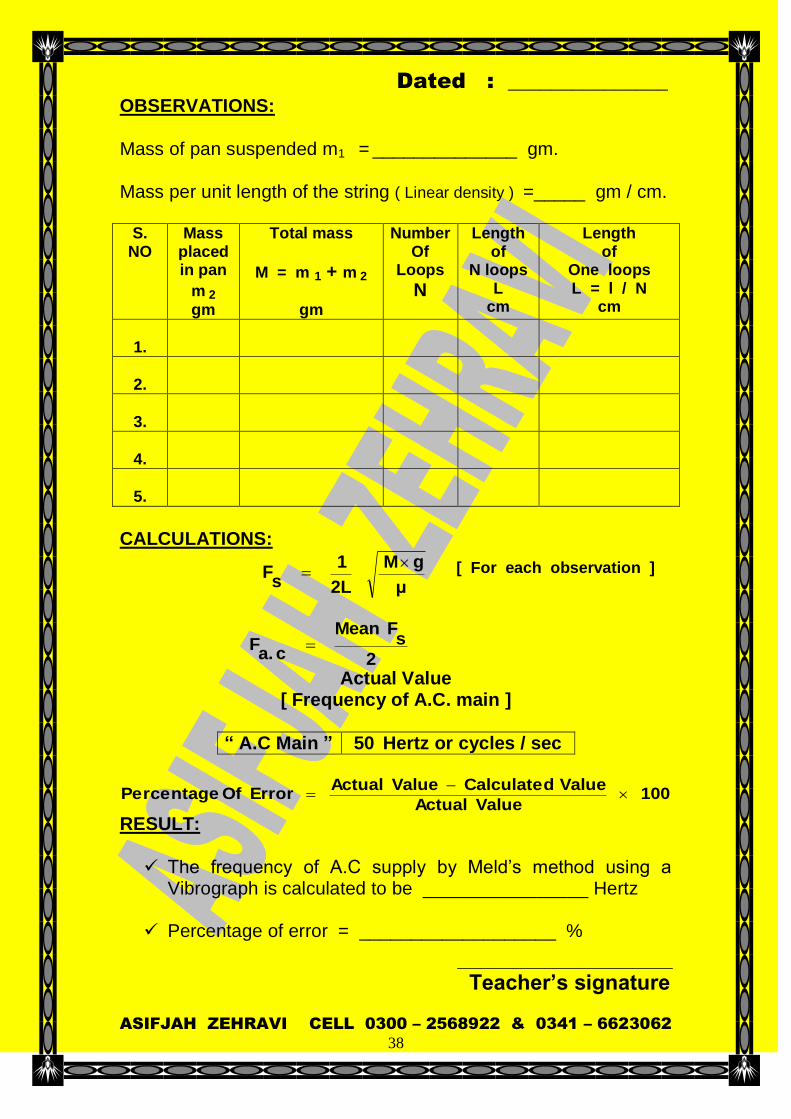
OBSERVATIONS: Mass of pan suspended m1 = ______________ gm. Mass per unit length of the string ( Linear density ) =_____ gm / cm.
S. NO
Mass placed in pan
m 2
gm
Total mass
M = m 1 + m 2
gm
Number Of
Loops
N
Length of
N loops L
cm
Length of
One loops L = l / N
cm
1.
2.
3.
4.
5.
CALCULATIONS:
μ
g M
2L
1
sF
[ For each observation ]
2
sF Mean
c a.
F
Actual Value [ Frequency of A.C. main ]
“ A.C Main ” 50 Hertz or cycles / sec
100 ValueActual
ValueCalculated ValueActual Error Of Percentage
RESULT: The frequency of A.C supply by Meld’s method using a
Vibrograph is calculated to be ________________ Hertz
Percentage of error = ___________________ %
___________________________
Teacher’s signature

Dated : _______________
ASIFJAH ZEHRAVI CELL 0300 – 2568922 & 0341 – 6623062
39
PRECAUTION: The string should be of uniform area of cross-section. It
should have no knots. The string should be stretched horizontally. The string, the vibrator or and the pulley should be in the
same straight line. Pan should be suspended freely and must be stationary
when readings are taken. The weights should be gently transferred to or from the pan. The wave, set up should be well defined, stationary and of
large amplitude. Pulley should be well oiled to reduce friction.
While taking the length of N loops the end loops must be omitted as initial and final node is not clear.
Pins should be placed at exact position of nodes. The string should have no knots.
SOURCES OF ERROR :
Non uniformity of linear density of string. Friction at pulley. Large least count of weights. Given linear density and weight. Personal error in measuring the length.

Dated : _______________
ASIFJAH ZEHRAVI CELL 0300 – 2568922 & 0341 – 6623062
40
EXPERIMENT NO . 11
OBJECT: To prove that the photo current is directly proportional to the intensity of light falling on photocell photo cell.
or Too verify the inverse square law by using a APPARATUS: Photo voltaic cell, Micro ammeter , Electric lamp , Meter scale , A – C Main supply and connecting wires. WORKING FORMULA: For inverse square law of radiation
Intensity of light E 2d
1
From the experiment
Photo electric current I 2d
1
Hence Intensity of light E Photo electric current I
E I
Where
d is the distance between the source of light and photocell
CIRCUIT DIAGRAM:
Dated : _______________
ASIFJAH ZEHRAVI CELL 0300 – 2568922 & 0341 – 6623062
41
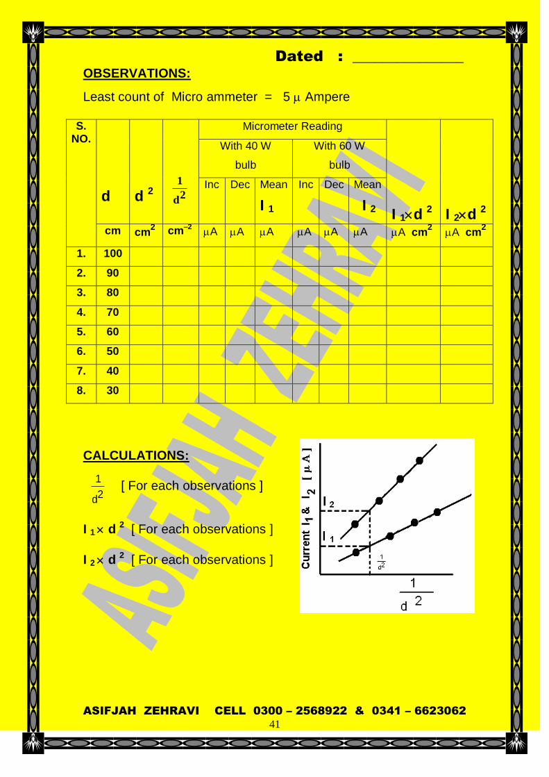
OBSERVATIONS:
Least count of Micro ammeter = 5 Ampere
CALCULATIONS:
2d
1 [ For each observations ]
I 1 d 2 [ For each observations ]
I 2 d 2 [ For each observations ]
S. NO.
d
d 2
2d
1
Micrometer Reading
I 1d 2
I 2d 2
With 40 W
bulb
With 60 W
bulb
Inc Dec Mean
I 1
Inc Dec Mean
I 2
cm cm2 cm–2 A A A A A A A cm
2 A cm
2
1. 100
2. 90
3. 80
4. 70
5. 60
6. 50
7. 40
8. 30
Dated : _______________
ASIFJAH ZEHRAVI CELL 0300 – 2568922 & 0341 – 6623062
42
RESULT:
The graph between current I and 2d
1 is a straight line which confirm
that the photoelectric current is directly proportional to the intensity of light
The values of I 1 d 2 and I 2 d 2 are constant for each bulb.
The value of
2I1I
is found to be _______
___________________________
Teacher’s signature PRECAUTION:
Connections must be tight and free from insulating material at the end.
The height of lamp and height of photocell should be same. Distance should be measured carefully. Zero error of micro ammeter should be noted. Least count of micro ammeter should be noted. Window of photocell should be opened after the lamp is
switched on. Personal movement should minimum so that light is not
blocked.
SOURCES OF ERROR: Large least count of micro ammeter. Height of lamp or photocell may not be same. Presence of light in the surroundings. Change in the illumination of light in the surrounding.

Dated : _______________
ASIFJAH ZEHRAVI CELL 0300 – 2568922 & 0341 – 6623062
43
EXPERIMENT NO . 12
OBJECT: To determine the mechanical equivalent of heat [ Value of J ] by Calander and Barne’s method. APPARATUS: Callender and Barne’s apparatus , Constant pressure head device Ammeter , Voltmeter , Rheostat , Two Thermometer , Accumulator , Physical balance , Stop watch and Connecting wires.
WORKING FORMULA: )
IT
FT ( C m
t I V J
Where
V is the the voltage applied across the resistor. I is the current passed through the resistor for t sec. t is the time for which the mass of water is collected.
m c is the mass of water collected.
TI is the temperature of water [ At Inlet ] TF is the temperature of water. [ At Outlet ]
CIRCUIT DIAGRAM:

Dated : _______________
ASIFJAH ZEHRAVI CELL 0300 – 2568922 & 0341 – 6623062
44
OBSERVATIONS:
1. Least count of voltmeter = ___________________________ Volts 2. Least count of Ammeter = ___________________________ Amps
3. Least count of thermometer = ________________________ C
4. Mass of empty beaker = m b = _______________________ gm.
5. Mass of beaker + water = M = ______________________ gm.
6. Mass of water collected = m = [ M – m b ] ___________ gm.
7. Specific heat of water = S b = 1 Cal / gms °C
8. The voltage applied across the resistor = V = __________ Volts
9. Current passed through the resistor = I = ___________ Amp
10. Time for which the current is passed = t = ________________ min
11. Initial Temperature of water [ At Inlet ] = TI = _______°C
12. Final temperature of water [ At Outlet ] = TF = ________°C
S. NO
Time ( t )
Voltage ( V )
Current ( I )
Temperature At Inlet
( T1 ) °C
Temperature At Outlet
( T2 ) °C
minutes Volts Amp °C °C
1.
2.
3.
4.
5.
6.

Dated : _______________
ASIFJAH ZEHRAVI CELL 0300 – 2568922 & 0341 – 6623062
45
CALCULATIONS:
Time for which the current is passed = t = _____ min 60 = _____Sec
)
IT
FT ( C m
t I V J
Actual Value [ Value of J ( Mechanical equivalent of heat ) ]
“ J “ 4.19 Joules / calorie
100 ValueActual
ValueCalculated ValueActual Error Of Percentage
RESULT:
The mechanical equivalent of heat [ Value of J ] by Calander
and Barne’s method is calculated to be ________ J / cal.
Percentage of error = ___________________ %
___________________________
Teacher’s signature PRECAUTION: There should be no air bubbles in the tube. Turns of the resistor wire may not touch each other or side of
the tube. Current must be switched on after maintaining a steady flow
of water through the tube. The tube must be air tight so that there should be no leakage
of water SOURCES OF ERROR : Inaccuracy of stopwatch. There may be air bubbles in the tube. The most important source of error is the loss of heat due to
radiation.

Dated : _______________
ASIFJAH ZEHRAVI CELL 0300 – 2568922 & 0341 – 6623062
46
EXPERIMENT NO . 13
OBJECT: To determine the temperature coefficient of resistance of the given wire. APPARATUS: Meter bridge, Galvanometer, Resistance box, Cell, Thermometer , Given coil , One way key and Connecting wires. THEORY: The resistance of a pure metal wire changes with temperature according to the relation
R t = R0 [ 1 + t + t 2 ]
Where and are constants R t and R0 are the resistances of the
metal at temperatures of t C and 0 C respectively .
The constant is very small compared with and for moderate temperature range the above relation can be written as
R t = R0 [ 1 + t ]
The constant is known as temperature coefficient of resistance.
If R t and R0 are the resistances of a metal at t C and 0 C are
known the value of can be computed by the relation
t
0R
0
R - t
R
2t [
0R
0
R - t
R
]1 t
However the measurement of resistance R0 at 0can be avoided. If R1 and R2 are the resistances of the metal wire at t1 ( say room temperature ) and t2 ( say boiling point of water ) are measured ,
then the value of can be determined by the relation.
]
1t
2R
2t
1R [
1
R - 2
R α

Dated : _______________
ASIFJAH ZEHRAVI CELL 0300 – 2568922 & 0341 – 6623062
47
WORKING FORMULA:
2t [
0R
0
R - t
R
]1 t
, ]
1t
2R
2t
1R [
1
R - 2
R α
Where
is the temperature coefficient of resistance of the given wire.
R t is the resistances of the metal wire at t C
R0 is the resistances of the metal wire at 0 C R1 is the resistance of the metal wire at t1 ( say room
temperature ) R2 is the resistance of the metal wire at t2 (say boiling point
of water ) T1 is the room temperature T2 is the boiling point of water
CIRCUIT DIAGRAM:

Dated : _______________
ASIFJAH ZEHRAVI CELL 0300 – 2568922 & 0341 – 6623062
48
OBSERVATIONS: Least count of thermometer = ________________________ °C S.
NO Temperature
At Inlet T
°C
Known Resistance
R
Ohm
LX
cm
LR
cm
RL
X
L R X
Ohm
1.
Room temp
2.
100
3.
90
4.
80
5.
70
6.
60
7.
50
CALCULATIONS:
2t [
0R
0
R - t
R
]1 t
]
1t
2R
2t
1R [
1
R - 2
R α
Actual Value [ Temperature coefficient of resistance for Nichrome wire ]
“ “ 0.00017 Per degree centigrade
[ Temperature coefficient of resistance for Manganin wire ]
“ “ 0.00001 Per degree centigrade
100 ValueActual
ValueCalculated ValueActual Error Of Percentage
Dated : _______________
ASIFJAH ZEHRAVI CELL 0300 – 2568922 & 0341 – 6623062
49
RESULT: The temperature coefficient of resistance of the given wire is
calculated to be ______________ per degree centigrade.
Percentage of error = ___________________ %
___________________________
Teacher’s signature PRECAUTION: All connections should be neat and tight. Short and thick connecting wires should be used. The jockey must have sharp edge. Avoid the sliding of jockey on the wire rather it should be
gently tapped over it. The plugs of resistance box should be tight in their gaps. Care should be taken in handling the apparatus.
SOURCES OF ERROR : Loose connections Error due to the sliding of jockey on the wire. Use of long and thin connecting wires may add more
resistance in the circuit. Loose plugs in the resistance box . Jockey may not be of sharp edge . Fluctuation of current in the circuit.
Dated : _______________
ASIFJAH ZEHRAVI CELL 0300 – 2568922 & 0341 – 6623062
50
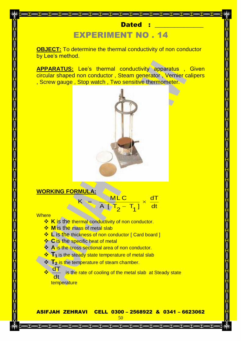
EXPERIMENT NO . 14
OBJECT: To determine the thermal conductivity of non conductor by Lee’s method. APPARATUS: Lee’s thermal conductivity apparatus , Given circular shaped non conductor , Steam generator , Vernier calipers , Screw gauge , Stop watch , Two sensitive thermometer.
WORKING FORMULA:
dt
dT
] 1
T 2
T [A
C L M K
Where K is the thermal conductivity of non conductor. M is the mass of metal slab L is the thickness of non conductor [ Card board ] C is the specific heat of metal A is the cross sectional area of non conductor.
T1 is the steady state temperature of metal slab
T2 is the temperature of steam chamber.
dt
dTis the rate of cooling of the metal slab at Steady state
temperature
Dated : _______________
ASIFJAH ZEHRAVI CELL 0300 – 2568922 & 0341 – 6623062
51
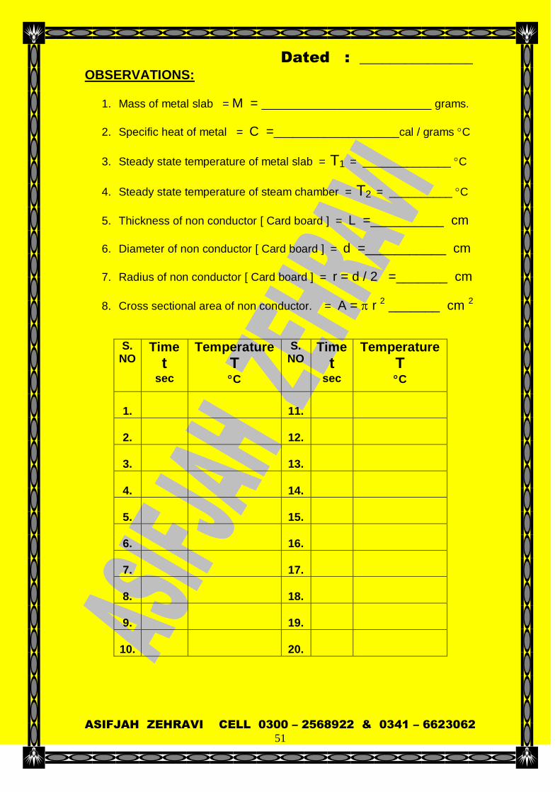
OBSERVATIONS:
1. Mass of metal slab = M = ___________________________ grams.
2. Specific heat of metal = C =____________________cal / grams C
3. Steady state temperature of metal slab = T1 = ______________ C
4. Steady state temperature of steam chamber = T2 = __________ C
5. Thickness of non conductor [ Card board ] = L =__________ cm
6. Diameter of non conductor [ Card board ] = d =___________ cm
7. Radius of non conductor [ Card board ] = r = d / 2 =_______ cm
8. Cross sectional area of non conductor. = A = r 2 _______ cm 2
S. NO
Time
t
sec
Temperature
T
C
S. NO
Time
t
sec
Temperature
T
C
1.
11.
2.
12.
3.
13.
4.
14.
5.
15.
6.
16.
7.
17.
8.
18.
9.
19.
10.
20.

Dated : _______________
ASIFJAH ZEHRAVI CELL 0300 – 2568922 & 0341 – 6623062
52
CALCULATIONS:
From graph d T = _____________ K d t = _____________ min
Rate of cooling of the metal Slab at steady state
dt
dT = ______________
dt
dT
] 1
T 2
T [A
C L M K
Actual Value
[ Thermal conductivity of poor conductor ]
Cork board 0.00011 cal / sec / cm / C
100 ValueActual
ValueCalculated ValueActual Error Of Percentage
RESULT: The thermal conductivity of non conductor by Lee’s method
is calculated to be ______________ cal / sec / cm / C
Percentage of error = ___________________ %
___________________________
Teacher’s signature PRECAUTION: Least count of stop watch should be noted and graduation on
stopwatch should be studied carefully before starting the experiment.
Diameter of metallic slab , card board and steam chamber must be equal.
Surface of the metallic slab and card board must be smooth so that they come in good thermal contact.

Dated : _______________
ASIFJAH ZEHRAVI CELL 0300 – 2568922 & 0341 – 6623062
53
SOURCES OF ERROR : Inaccuracy of stopwatch. Diameter of card board may not be equal to diameter of
metallic slab and steam chamber. Loss of heat from edges of the slab and the bad conductor. Presence of condensed water in the steam chamber is an
important source of error.

Dated : _______________
ASIFJAH ZEHRAVI CELL 0300 – 2568922 & 0341 – 6623062
54
EXPERIMENT NO . 15
OBJECT: To determine the wavelength of sodium light [ D – lines ] by diffraction grating
APPARATUS: Spectrometer , Diffraction grating , Sodium lamp , Sprit level.
WORKING FORMULA:
N = d Sin N
θ Sin d λ
Where
is the wave length of sodium light. d is the grating element. is the angle of diffraction of the sodium light. N is the order of spectrum.

Dated : _______________
ASIFJAH ZEHRAVI CELL 0300 – 2568922 & 0341 – 6623062
55
OBSERVATIONS: Least count of stop watch = 1 minute.
Number of lines ruled on the grating = ________lines / inch.
Grating element = ] [
cm 2.54
lines of no
inch 1 d = _______cm
S
NO
Order Of
Image
Lines Diffraction reading on
Difference Of
Readings
2 = A – B
Angle of diffraction
Wave length
Right
side [ A ]
Left side
[ B ]
deg deg deg deg cm
1. I
D1
2.
I I
D2
CALCULATIONS: N
θ Sin d λ
Actual Value
[ Wave length of spectral lines of sodium ] Yellow D 1
5896 10 – 8
cm 5896 oA
Yellow D 2 5890 10
– 8 cm 5890
oA
100 ValueActual
ValueCalculated ValueActual Error Of Percentage
RESULT:
The wavelength of sodium light [ D – lines ] by diffraction
grating is calculated to be ______ 10 – 8
cm ______ oA
Percentage of error = ___________________ %
___________________________
Teacher’s signature
Dated : _______________
ASIFJAH ZEHRAVI CELL 0300 – 2568922 & 0341 – 6623062
56
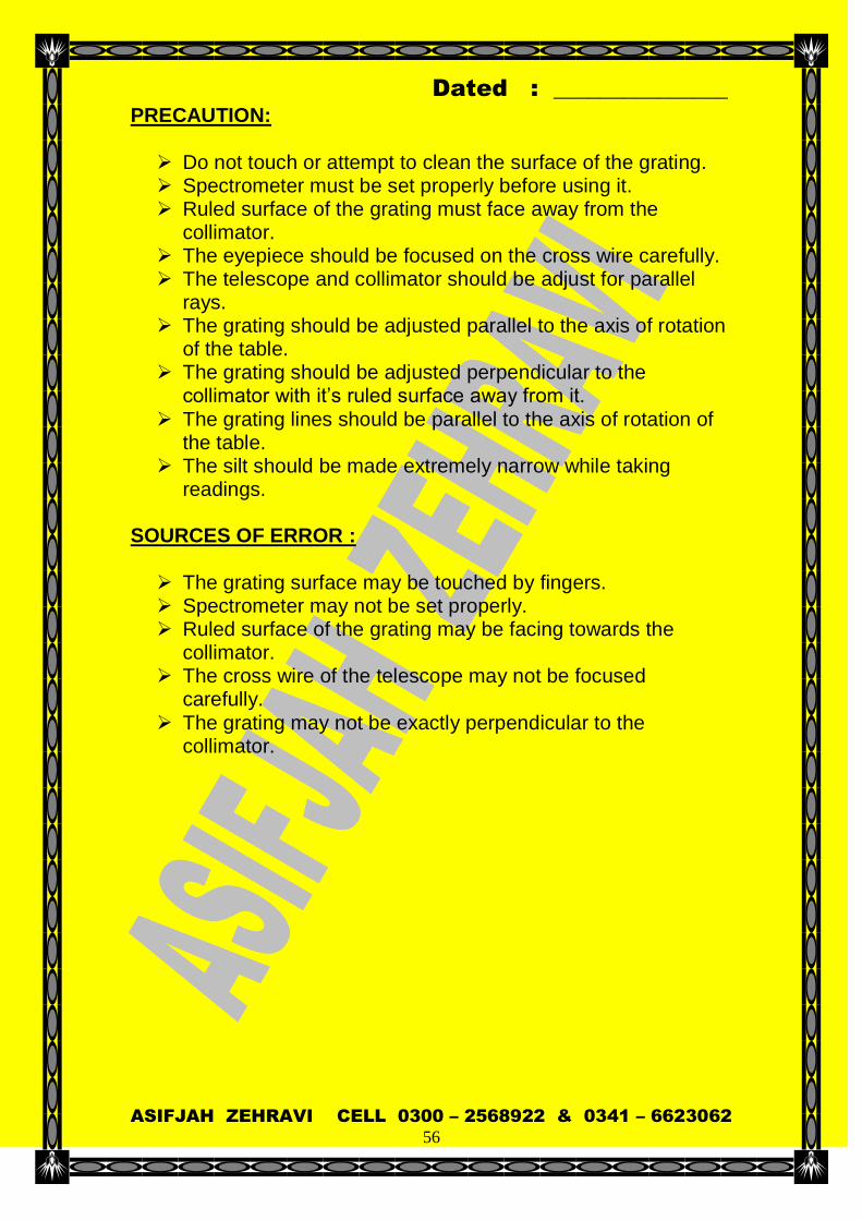
PRECAUTION: Do not touch or attempt to clean the surface of the grating. Spectrometer must be set properly before using it. Ruled surface of the grating must face away from the
collimator. The eyepiece should be focused on the cross wire carefully. The telescope and collimator should be adjust for parallel
rays. The grating should be adjusted parallel to the axis of rotation
of the table. The grating should be adjusted perpendicular to the
collimator with it’s ruled surface away from it.
The grating lines should be parallel to the axis of rotation of the table.
The silt should be made extremely narrow while taking readings.
SOURCES OF ERROR : The grating surface may be touched by fingers. Spectrometer may not be set properly. Ruled surface of the grating may be facing towards the
collimator. The cross wire of the telescope may not be focused
carefully. The grating may not be exactly perpendicular to the
collimator.

Dated : _______________
ASIFJAH ZEHRAVI CELL 0300 – 2568922 & 0341 – 6623062
57
EXPERIMENT NO . 16
OBJECT: To determine the wavelength of sodium light by Newton’s ring.
APPARATUS: Sodium lamp , Sprit level., Convex lens of suitable focal length ( Usually lens of long focal length is used ) Plane glass plate ,Traveling microscope.
WORKING FORMULA: wavelength of sodium light by Newton’s
ring can be calculated as
] m - n [ R 4
2mD2
nD λ
Where
is the wave length of light used.
D n is the diameter of nth dark ring ( Outer ring )
D m is the diameter of m th dark ring ( Inner ring
R is the radius of curvature of the lens. OBSERVATIONS: Least count of traveling micrometer = ____________cm.
Radius of curvature of lens used = R = _____________cm
S
NO
Ring Number
Microscope reading on Difference Of
Readings
2 = A – B
Right side [ A ]
Left side [ B ]
cm cm cm
1.
2.
3.
4.
CALCULATIONS: wavelength of sodium light by Newton’s ring .

Dated : _______________
ASIFJAH ZEHRAVI CELL 0300 – 2568922 & 0341 – 6623062
58
] m - n [ R 4
2mD2
nD λ
Actual Value
[ wavelength of sodium light “ “ ]
Yellow D 1 5896 10
– 8 cm 5896
oA
Yellow D 2 5890 10
– 8 cm 5890
oA
100 ValueActual
ValueCalculated ValueActual Error Of Percentage
RESULT: The wavelength of sodium light by Newton’s ring is
calculated to be ________ cm or ___________ oA
Percentage of error = ___________________ %
___________________________
Teacher’s signature PRECAUTION: A lens of large radius of curvature should be used.
The point of interaction of crosswire should coincide with the centre of ring system.
One of the crosswire should be perpendicular to the scale of microscope.
The microscope should be moved in the same direction while measuring the diameter of a ring to avoid back lash error.
The radius of curvature of the surface of the lens in contact with the glass plate should be measured.
Lens and the glass plate should be cleaned properly so that no dust particles remains between them at the point of contact, this is necessary for making the center of rings always dark.
Screw of the travelling microscope must be rotated as for as possible in one direction
Dated : _______________
ASIFJAH ZEHRAVI CELL 0300 – 2568922 & 0341 – 6623062
59
The glass plate must be held at an angle of 45 to the light beam so that light must fall perpendicularly on the lens.
Travelling microscope readings must be taken accurately.
SOURCES OF ERROR : Lens and glass plate may not be clean. Readings of microscope may not be accurate.
Micro scope screw may have slight backlash error.
The glass plate may not be held at an angle of 45 to the beam of light.
Dated : _______________
ASIFJAH ZEHRAVI CELL 0300 – 2568922 & 0341 – 6623062
60
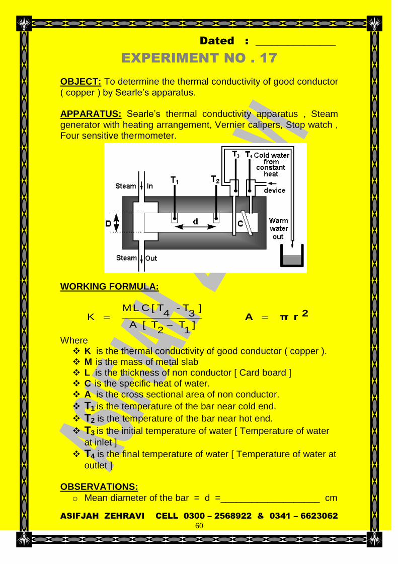
EXPERIMENT NO . 17
OBJECT: To determine the thermal conductivity of good conductor ( copper ) by Searle’s apparatus. APPARATUS: Searle’s thermal conductivity apparatus , Steam generator with heating arrangement, Vernier calipers, Stop watch , Four sensitive thermometer.
WORKING FORMULA:
]
1T
2T [A
] 3
T - 4
T [ C L M K
2 r π A
Where K is the thermal conductivity of good conductor ( copper ). M is the mass of metal slab L is the thickness of non conductor [ Card board ] C is the specific heat of water. A is the cross sectional area of non conductor.
T1 is the temperature of the bar near cold end.
T2 is the temperature of the bar near hot end.
T3 is the initial temperature of water [ Temperature of water
at inlet ]
T4 is the final temperature of water [ Temperature of water at
outlet ] OBSERVATIONS:
o Mean diameter of the bar = d =___________________ cm

Dated : _______________
ASIFJAH ZEHRAVI CELL 0300 – 2568922 & 0341 – 6623062
61
o Radius of the bar = r = d / 2 = _________________ cm
o Distance between two holes on the bar = L =________ cm
o Temperature of the bar near cold end = T1 = __________ C
o Temperature of the bar near hot end = T2 = __________ C
o Temperature of water at inlet = T3 = ________________ C
o Temperature of water at outlet = T4 = _______________ C
o Mass of empty beaker = m 1 = ________________ grams.
o Mass of beaker + water = m 2 = ______________ grams.
o Mass of water collected = M = [ m 2 – m 1 ] = _____ grams.
o Specific heat of water = C = 1 cal / grams C
o Time for which M gram of water is collected = t = ____Sec
S. NO
Time t (min)
T1 C
T2 C
T3 C
T4 C
1 0
2 05
3 10
4 15
5 20
CALCULATIONS:
]
1T
2T [A
] 3
T - 4
T [ C L M K
2 r π A
Actual Value [ Thermal conductivity of the given bar ]
Copper 0.99 cal / sec / cm / C
100 ValueActual
ValueCalculated ValueActual Error Of Percentage

Dated : _______________
ASIFJAH ZEHRAVI CELL 0300 – 2568922 & 0341 – 6623062
62
RESULT:
The thermal conductivity of the material of the given bar by
Searle’s apparatus is calculated to be __ cal / sec / cm / C
Percentage of error = ___________________ %
___________________________
Teacher’s signature PRECAUTION: Least count of stop watch should be noted and graduation on
stopwatch should be studied carefully before starting the experiment.
Diameter of the metallic bar must be measured accurately. Sides of the bar must be well insulated by wrapping it in a
thick coating of felt within the wooden box. Water must be circulated around the colder end of the bar at
such a constant rate that there must be a temperature
difference of at least 5C between inlet and out let water. Readings must be recorded when all thermometers show steady state.
SOURCES OF ERROR : Inaccuracy of stopwatch. Diameter of bar may not be measured accurately. Bar may not be properly insulated due to which there may be
loss of heat through sides of the bar. In accurate measurement of rate of flow of water.

Dated : _______________
ASIFJAH ZEHRAVI CELL 0300 – 2568922 & 0341 – 6623062
63
EXPERIMENT NO . 18
OBJECT: To determine the specific rotation of sugar solution by Polari meter. APPARATUS: Polari meter, sodium lamp , pure cane sugar , balance , measuring cylinder , beaker , etc.

Dated : _______________
ASIFJAH ZEHRAVI CELL 0300 – 2568922 & 0341 – 6623062
64
WORKING FORMULA: The specific rotation of sugar solution is given by
l m
1000 S
Where S is the specific rotation of sugar solution
is the angle through which the plane polarized light is rotated by the sugar solution.
m is the concentration of the sugar solution ( in % ) = Mass of sugar dissolved in 100 ml of distilled water.
l is the length of the tube filled with the solution through which light is passed.
OBSERVATIONS:
o Least count of polarimeter scale = d =_________Degrees o Length of polarimeter tube = l = _____________ cm
o Polarimeter reading for equally dark position with distilled
water = “ 1” = ______________Degrees.
S.
NO Strength of
sugar solution
“m”
Polarimeter reading for equally dark position with sugar solution
“2”
Angle of rotation
= [2 – 1]
Specific rotation
l m
1000
1 2 Mean
% Deg Deg Deg Deg Deg
1 1%
2 2%
3 3%
4 4%
5 5%
CALCULATIONS:
l m
1000 S

Dated : _______________
ASIFJAH ZEHRAVI CELL 0300 – 2568922 & 0341 – 6623062
65
Actual Value
[ The specific rotation of cane sugar ]
Cane sugar 66.67
100 ValueActual
ValueCalculated ValueActual Error Of Percentage
RESULT:
The specific rotation of sugar solution at _____C is calculated to be ______________
Percentage of error = ___________________ %
___________________________
Teacher’s signature PRECAUTION: Least
SOURCES OF ERROR : Inaccuracy