


Languages
Pages
Legal

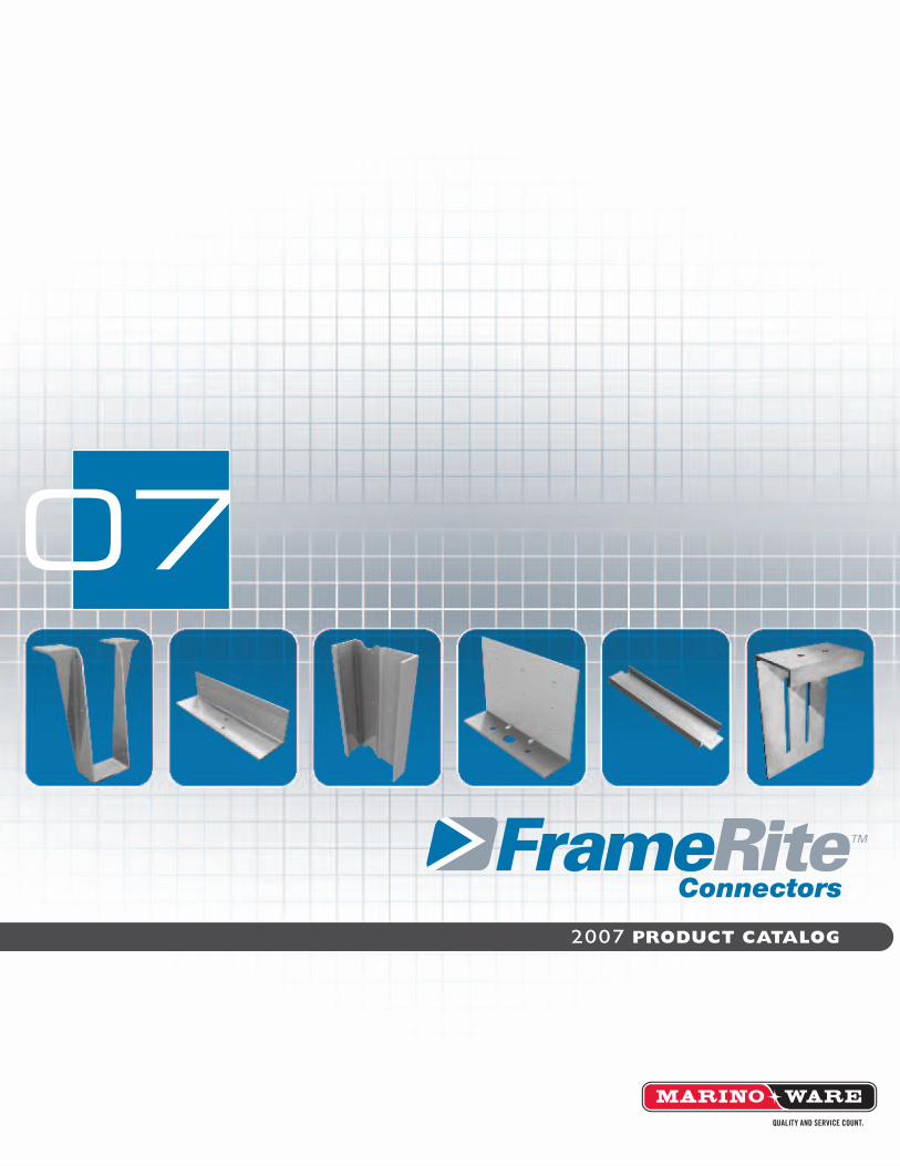
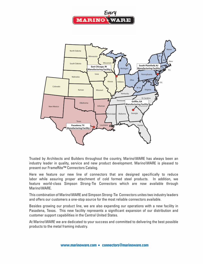
Trusted by Architects and Builders throughout the country, Marino\WARE has always been an industry leader in quality, service and new product development. Marino\WARE is pleased to present our FrameRite™ Connectors Catalog.
Here we feature our new line of connectors that are designed specifi cally to reduce labor while assuring proper attachment of cold formed steel products. In addition, we feature world-class Simpson Strong-Tie Connectors which are now available through Marino\WARE.
This combination of Marino\WARE and Simpson Strong-Tie Connectors unites two industry leaders and offers our customers a one-stop source for the most reliable connectors available.
Besides growing our product line, we are also expanding our operations with a new facility in Pasadena, Texas. This new facility represents a signifi cant expansion of our distribution and customer support capabilities in the Central United States.
At Marino\WARE we are dedicated to your success and committed to delivering the best possible products to the metal framing industry.
www.marinoware.com • [email protected]

Joist Framing Connectors
Table of Contents
Joist Framing Connectors ............................................................................................................................. 1Solid Blocking (JB)
Web Stiffener (JS) Utility Clips (UA) Steel Joist Hanger (S/HJCT) Hanger (S/LBV) Framing Plates (LPT5) Ledger Connector System (ICFVL) Bridle Hangers (BH) Reinforcing and Skewable Angles (S/LS) Coiled Straps (CS)
Roof and Truss Connectors ........................................................................................................................... 9Utility Clips (UA)
Seismic and Hurricane Ties (S/H1A) Seismic and Hurricane Ties (S/H) Twist Straps (MTS) Strap Ties (ST/LSTA/MST/MSTA) Katz Blocking (KB) Gusset Plate (Unpunched) (GP)
Rigid Connectors .......................................................................................................................................... 13Utility Clips (UA)Rigid Clip Connector (RCC)
Holdowns (S/HD) Tension Ties (S/LTT and S/HTT)
Defl ection Connectors ................................................................................................................................. 15 WSC 950 and WSC 1500 Outrigger Defl ex Slotted Track
Bridging and Bracing Connectors ............................................................................................................. 19BridgeRite Clips (BR)
Coiled Straps (CS) Katz Blocking (KB) Tension Bridging (TB)
Specialty Products ....................................................................................................................................... 21Breakaway Clips (BA)
Grommet U-Flex Track
Connector Selector
Roof and Truss Connectors
Rigid Connectors
Defl ection Connectors
Bridging & Bracing Connectors
Specialty Products
NEW
NEW
NEW
NEW
NEW

Technical Support:Marino\WARE offers its customers free expert technical assistance with the selection and use of our FrameRite Connectors. Technical representatives are standing by and ready to assist you. Technical Services can be reached at 866-545-1545, at [email protected] or at [email protected]. In most cases Technical Services representatives can provide immediate responses. In addition to Technical Services, Marino\WARE’s DesignRite Engineering services can design the FrameRite Connectors best suited for your project detailed as part of your shop drawings when required by the project.

� 2007 FrameRite Connectors Product Catalog
Jois
t Fr
amin
g C
on
nec
tors
Joist Blocking is pre-cut to fit securely between joists to prevent joist rotation. Joist Blocking is a one piece system in lieu of the typical 3 piece detail offering an economical alternative to installing conventional clips and solid web members.MATERIAL: 16 ga (54 mil) 50ksiFINISH: Galvanized – G90INSTALLATION:• Position the pre-cut Joist Blocking to fit securely between the joist.• (4) #10 - 16 screws are required to secure the blocking to the joist flanges using the pre-punched
holes.• Solid blocking should be installed 7’ o.c. maximum along the joist length.• Fits up to 2” flange joist product.• Blocking for flanges from 2” to 3” available as a special order.
Solid Blocking (JB)Model No. Depth Spacing
800JB-12 8” 12
925JB-12 91/4” 12
1000JB-12 10” 12
1125JB-12 111/4” 12
1200JB-12 12” 12
1400JB-12 14” 12
800JB-16 8” 16
925JB-16 91/4” 16
1000JB-16 10” 16
1125JB-16 111/4” 16
1200JB-16 12” 16
1400JB-16 14” 16
800JB-24 8” 24
925JB-24 91/4” 24
1000JB-24 10” 24
1125JB-24 111/4” 24
1200JB-24 12” 24
1400JB-24 14” 24
Packaged 10 pieces per box.
Web Stiffeners are used to provide reinforcement of joist webs to prevent crippling. Web reinforcement is often required by design to enhance the load capacity of joists. Web stiffeners are installed on the outside of the C-joist.MATERIAL: 16 ga (54 mil) 50ksiFINISH: Galvanized – G90INSTALLATION:• Web stiffeners are centered within the load or reaction bearing width.• Web stiffeners require full bearing along their supported ends.• (4-6) #10 - 16 screws are required to attach the stiffener to the joist web using pre-punched
holes.
Web Stiffener (JS) 35/8”
Leng
th
Model No. Length
8JS-362 8”
925JS-362 91/4”
10JS-362 10”
1125JS-362 111/4”
12JS-362 12”
14JS-362 14”
Packaged 24 pieces per box.
NEW

2007 FrameRite Connectors Product Catalog2
Jois
t Fr
amin
g C
on
nec
tors
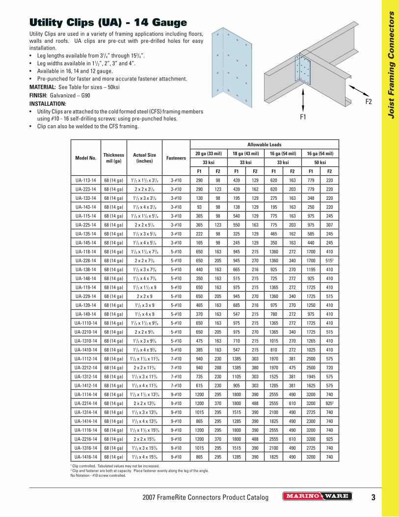
Utility Clips are used in a variety of framing applications including fl oors, walls and roofs. UA clips are pre-cut with pre-drilled holes for easy installation.• Leg lengths available from 31/4” through 153/4”.• Leg widths available in 11/2”, 2”, 3” and 4”.• Available in 16, 14 and 12 gauge. • Pre-punched for faster and more accurate fastener attachment.MATERIAL: See Table for sizes – 50ksiFINISH: Galvanized – G90INSTALLATION:• Utility Clips are attached to the cold formed steel (CFS) framing members
using #10 - 16 self-drilling screws: using pre-punched holes. • Clip can also be welded to the CFS framing.
Utility Clips (UA) - 16 Gauge
Model No. Thicknessmil (ga)
Actual Size (inches) Fasteners
Allowable Loads
20 ga (33 mil) 18 ga (43 mil) 16 ga (54 mil) 16 ga (54 mil)
33 ksi 33 ksi 33 ksi 50 ksi
F1 F2 F1 F2 F1 F2 F1 F2
UA-113-16 54 (16 ga) 11/2 x 11/2 x 31/4 3-#10 290 98 439 129 620 1371 779 1371
UA-223-16 54 (16 ga) 2 x 2 x 31/4 3-#10 290 123 439 1381 620 1381 779 1371
UA-133-16 54 (16 ga) 11/2 x 3 x 31/4 3-#10 130 98 195 129 275 1361 348 1371
UA-143-16 54 (16 ga) 11/2 x 4 x 31/4 3-#10 93 98 138 129 195 1371 250 1371
UA-115-16 54 (16 ga) 11/2 x 11/2 x 51/4 3-#10 365 98 540 129 775 163 975 2241
UA-225-16 54 (16 ga) 2 x 2 x 51/4 3-#10 365 123 540 163 775 203 975 2241
UA-135-16 54 (16 ga) 11/2 x 3 x 51/4 3-#10 220 98 325 129 465 2241 595 2241
UA-145-16 54 (16 ga) 11/2 x 4 x 51/4 3-#10 165 98 245 129 350 163 440 2241
UA-118-16 54 (16 ga) 11/2 x 11/2 x 73/4 5-#10 650 163 945 215 1355 272 1700 3301
UA-228-16 54 (16 ga) 2 x 2 x 73/4 5-#10 650 205 945 270 1360 3301 1700 3301
UA-138-16 54 (16 ga) 11/2 x 3 x 73/4 5-#10 448 164 665 215 925 270 1185 330
UA-148-16 54 (16 ga) 11/2 x 4 x 73/4 5-#10 350 163 515 215 725 272 925 3301
UA-119-16 54 (16 ga) 11/2 x 11/2 x 9 5-#10 650 163 945 215 1365 272 1710 3831
UA-229-16 54 (16 ga) 2 x 2 x 9 5-#10 650 205 945 270 1365 340 1710 3831
UA-139-16 54 (16 ga) 11/2 x 3 x 9 5-#10 460 164 700 215 975 270 1235 3831
UA-149-16 54 (16 ga) 11/2 x 4 x 9 5-#10 370 163 547 215 780 272 975 3831
UA-1110-16 54 (16 ga) 11/2 x 11/2 x 93/4 5-#10 650 163 945 215 1365 272 1710 4151
UA-2210-16 54 (16 ga) 2 x 2 x 93/4 5-#10 650 205 980 270 1365 340 1720 4151
UA-1310-16 54 (16 ga) 11/2 x 3 x 93/4 5-#10 475 164 710 215 1015 270 1285 4151
UA-1410-16 54 (16 ga) 11/2 x 4 x 93/4 5-#10 385 163 547 215 810 272 1015 4151
UA-1112-16 54 (16 ga) 11/2 x 11/2 x 113/4 7-#10 940 230 1385 303 1970 381 2500 5001
UA-2212-16 54 (16 ga) 2 x 2 x 113/4 7-#10 940 288 1385 380 1970 475 2500 5001
UA-1312-16 54 (16 ga) 11/2 x 3 x 113/4 7-#10 735 230 1085 302 1525 380 1975 5001
UA-1412-16 54 (16 ga) 11/2 x 4 x 113/4 7-#10 615 230 905 303 1285 381 1625 5001
UA-1114-16 54 (16 ga) 11/2 x 11/2 x 133/4 9-#10 1200 295 1800 390 2555 490 3200 5851
UA-2214-16 54 (16 ga) 2 x 2 x 133/4 9-#10 1200 370 1800 488 2555 5851 3200 5851
UA-1314-16 54 (16 ga) 11/2 x 3 x 133/4 9-#10 1000 295 1500 390 2125 490 2675 5851
UA-1414-16 54 (16 ga) 11/2 x 4 x 133/4 9-#10 865 295 1285 390 1825 490 2300 5851
UA-1116-16 54 (16 ga) 11/2 x 11/2 x 153/4 9-#10 1200 295 1800 390 2555 490 3200 6701
UA-2216-16 54 (16 ga) 2 x 2 x 153/4 9-#10 1200 370 1800 488 2555 610 3200 6701
UA-1316-16 54 (16 ga) 11/2 x 3 x 153/4 9-#10 1000 295 1500 390 2125 490 2675 6701
UA-1416-16 54 (16 ga) 11/2 x 4 x 153/4 9-#10 865 295 1285 390 1825 490 2300 6701
1 Clip controlled. Tabulated values may not be increased.2 Clip and fastener are both at capacity. Place fastener evenly along the leg of the angle.No Notation - #10 screw controlled.
32007 FrameRite Connectors Product Catalog
Jois
t Fr
amin
g C
on
nec
tors
Model No. Thicknessmil (ga)
Actual Size (inches) Fasteners
Allowable Loads
20 ga (33 mil) 18 ga (43 mil) 16 ga (54 mil) 16 ga (54 mil)
33 ksi 33 ksi 33 ksi 50 ksi
F1 F2 F1 F2 F1 F2 F1 F2
UA-113-14 68 (14 ga) 11/2 x 11/2 x 31/4 3-#10 290 98 439 129 620 163 779 220
UA-223-14 68 (14 ga) 2 x 2 x 31/4 3-#10 290 123 439 162 620 203 779 220
UA-133-14 68 (14 ga) 11/2 x 3 x 31/4 3-#10 130 98 195 129 275 163 348 220
UA-143-14 68 (14 ga) 11/2 x 4 x 31/4 3-#10 93 98 138 129 195 163 250 220
UA-115-14 68 (14 ga) 11/2 x 11/2 x 51/4 3-#10 365 98 540 129 775 163 975 245
UA-225-14 68 (14 ga) 2 x 2 x 51/4 3-#10 365 123 550 163 775 203 975 307
UA-135-14 68 (14 ga) 11/2 x 3 x 51/4 3-#10 222 98 325 129 465 162 585 245
UA-145-14 68 (14 ga) 11/2 x 4 x 51/4 3-#10 165 98 245 129 350 163 440 245
UA-118-14 68 (14 ga) 11/2 x 11/2 x 73/4 5-#10 650 163 945 215 1360 272 1700 410
UA-228-14 68 (14 ga) 2 x 2 x 73/4 5-#10 650 205 945 270 1360 340 1700 5152
UA-138-14 68 (14 ga) 11/2 x 3 x 73/4 5-#10 440 163 665 216 925 270 1195 410
UA-148-14 68 (14 ga) 11/2 x 4 x 73/4 5-#10 350 163 515 215 725 272 925 410
UA-119-14 68 (14 ga) 11/2 x 11/2 x 9 5-#10 650 163 975 215 1365 272 1725 410
UA-229-14 68 (14 ga) 2 x 2 x 9 5-#10 650 205 945 270 1360 340 1725 515
UA-139-14 68 (14 ga) 11/2 x 3 x 9 5-#10 465 163 685 216 975 270 1250 410
UA-149-14 68 (14 ga) 11/2 x 4 x 9 5-#10 370 163 547 215 780 272 975 410
UA-1110-14 68 (14 ga) 11/2 x 11/2 x 93/4 5-#10 650 163 975 215 1365 272 1725 410
UA-2210-14 68 (14 ga) 2 x 2 x 93/4 5-#10 650 205 975 270 1365 340 1725 515
UA-1310-14 68 (14 ga) 11/2 x 3 x 93/4 5-#10 475 163 710 215 1015 270 1265 410
UA-1410-14 68 (14 ga) 11/2 x 4 x 93/4 5-#10 385 163 547 215 810 272 1025 410
UA-1112-14 68 (14 ga) 11/2 x 11/2 x 113/4 7-#10 940 230 1385 303 1970 381 2500 575
UA-2212-14 68 (14 ga) 2 x 2 x 113/4 7-#10 940 288 1385 380 1970 475 2500 720
UA-1312-14 68 (14 ga) 11/2 x 3 x 113/4 7-#10 735 230 1105 303 1525 381 1945 575
UA-1412-14 68 (14 ga) 11/2 x 4 x 113/4 7-#10 615 230 905 303 1285 381 1625 575
UA-1114-14 68 (14 ga) 11/2 x 11/2 x 133/4 9-#10 1200 295 1800 390 2555 490 3200 740
UA-2214-14 68 (14 ga) 2 x 2 x 133/4 9-#10 1200 370 1800 488 2555 610 3200 9252
UA-1314-14 68 (14 ga) 11/2 x 3 x 133/4 9-#10 1015 295 1515 390 2100 490 2725 740
UA-1414-14 68 (14 ga) 11/2 x 4 x 133/4 9-#10 865 295 1285 390 1825 490 2300 740
UA-1116-14 68 (14 ga) 11/2 x 11/2 x 153/4 9-#10 1200 295 1800 390 2555 490 3200 740
UA-2216-14 68 (14 ga) 2 x 2 x 153/4 9-#10 1200 370 1800 488 2555 610 3200 925
UA-1316-14 68 (14 ga) 11/2 x 3 x 153/4 9-#10 1015 295 1515 390 2100 490 2725 740
UA-1416-14 68 (14 ga) 11/2 x 4 x 153/4 9-#10 865 295 1285 390 1825 490 3200 7401 Clip controlled. Tabulated values may not be increased.2 Clip and fastener are both at capacity. Place fastener evenly along the leg of the angle.No Notation - #10 screw controlled.
Utility Clips are used in a variety of framing applications including fl oors, walls and roofs. UA clips are pre-cut with pre-drilled holes for easy installation.• Leg lengths available from 31/4” through 153/4”.• Leg widths available in 11/2”, 2”, 3” and 4”.• Available in 16, 14 and 12 gauge. • Pre-punched for faster and more accurate fastener attachment.MATERIAL: See Table for sizes – 50ksiFINISH: Galvanized – G90INSTALLATION:• Utility Clips are attached to the cold formed steel (CFS) framing members
using #10 - 16 self-drilling screws: using pre-punched holes. • Clip can also be welded to the CFS framing.
Utility Clips (UA) - 14 Gauge
F1
F2

2007 FrameRite Connectors Product Catalog4
Jois
t Fr
amin
g C
on
nec
tors
Model No. Thicknessmil (ga)
Actual Size (inches) Fasteners
Allowable Loads
20 ga (33 mil) 18 ga (43 mil) 16 ga (54 mil) 16 ga (54 mil)
33 ksi 33 ksi 33 ksi 50 ksi
F1 F2 F1 F2 F1 F2 F1 F2
UA-113-12 97 (12 ga) 11/2 x 11/2 x 31/4 3-#10 290 98 439 129 620 163 779 245
UA-223-12 97 (12 ga) 2 x 2 x 31/4 3-#10 290 123 439 162 620 203 779 307
UA-133-12 97 (12 ga) 11/2 x 3 x 31/4 3-#10 130 98 195 129 275 163 348 245
UA-143-12 97 (12 ga) 11/2 x 4 x 31/4 3-#10 93 98 138 129 195 163 250 245
UA-115-12 97 (12 ga) 11/2 x 11/2 x 51/4 3-#10 365 98 540 129 775 163 975 245
UA-225-12 97 (12 ga) 2 x 2 x 51/4 3-#10 365 123 550 163 775 203 975 307
UA-135-12 97 (12 ga) 11/2 x 3 x 51/4 3-#10 222 98 325 129 465 162 585 245
UA-145-12 97 (12 ga) 11/2 x 4 x 51/4 3-#10 165 98 245 129 350 163 440 245
UA-118-12 97 (12 ga) 11/2 x 11/2 x 73/4 5-#10 650 163 945 215 1360 272 1700 410
UA-228-12 97 (12 ga) 2 x 2 x 73/4 5-#10 650 205 945 270 1360 340 1700 515
UA-138-12 97 (12 ga) 11/2 x 3 x 73/4 5-#10 440 163 665 216 925 270 1195 410
UA-148-12 97 (12 ga) 11/2 x 4 x 73/4 5-#10 350 163 515 215 725 272 925 410
UA-119-12 97 (12 ga) 11/2 x 11/2 x 9 5-#10 650 163 975 215 1365 272 1725 410
UA-229-12 97 (12 ga) 2 x 2 x 9 5-#10 650 205 975 270 1360 340 1725 515
UA-139-12 97 (12 ga) 11/2 x 3 x 9 5-#10 465 163 685 216 975 270 1250 410
UA-149-12 97 (12 ga) 11/2 x 4 x 9 5-#10 370 163 547 215 780 272 975 410
UA-1110-12 97 (12 ga) 11/2 x 11/2 x 93/4 5-#10 650 163 975 215 1365 272 1725 410
UA-2210-12 97 (12 ga) 2 x 2 x 93/4 5-#10 650 205 975 270 1365 340 1725 515
UA-1310-12 97 (12 ga) 11/2 x 3 x 93/4 5-#10 475 163 710 215 1015 270 1265 410
UA-1410-12 97 (12 ga) 11/2 x 4 x 93/4 5-#10 370 163 547 215 810 272 1025 410
UA-1112-12 97 (12 ga) 11/2 x 11/2 x 113/4 7-#10 385 230 1385 303 1970 381 2500 575
UA-2212-12 97 (12 ga) 2 x 2 x 113/4 7-#10 940 288 1385 380 1970 475 2500 720
UA-1312-12 97 (12 ga) 11/2 x 3 x 113/4 7-#10 735 230 1105 303 1525 381 1945 575
UA-1412-12 97 (12 ga) 11/2 x 4 x 113/4 7-#10 615 230 905 303 1285 381 1625 575
UA-1114-12 97 (12 ga) 11/2 x 11/2 x 133/4 9-#10 1200 295 1800 390 2555 490 3200 740
UA-2214-12 97 (12 ga) 2 x 2 x 133/4 9-#10 1200 370 1800 488 2555 610 3200 925
UA-1314-12 97 (12 ga) 11/2 x 3 x 133/4 9-#10 1015 295 1515 390 2100 490 2725 740
UA-1414-12 97 (12 ga) 11/2 x 4 x 133/4 9-#10 865 295 1285 390 1825 490 2300 740
UA-1116-12 97 (12 ga) 11/2 x 11/2 x 153/4 9-#10 1200 295 1800 390 2555 490 3200 740
UA-2216-12 97 (12 ga) 2 x 2 x 153/4 9-#10 1200 370 1800 488 2555 610 3200 925
UA-1316-12 97 (12 ga) 11/2 x 3 x 153/4 9-#10 1015 295 1515 390 2100 490 2725 740
UA-1416-12 97 (12 ga) 11/2 x 4 x 153/4 9-#10 865 295 1285 390 1825 490 3200 7401 Clip controlled. Tabulated values may not be increased.2 Clip and fastener are both at capacity. Place fastener evenly along the leg of the angle.No Notation - #10 screw controlled.
Utility Clips are used in a variety of framing applications including fl oors, walls and roofs. UA clips are pre-cut with pre-drilled holes for easy installation.• Leg lengths available from 31/4” through 153/4”.• Leg widths available in 11/2”, 2”, 3” and 4”.• Available in 16, 14 and 12 gauge. • Pre-punched for faster and more accurate fastener attachment.MATERIAL: See Table for sizes – 50ksiFINISH: Galvanized – G90INSTALLATION:• Utility Clips are attached to the cold formed steel (CFS) framing members
using #10 - 16 self-drilling screws: using pre-punched holes. • Clip can also be welded to the CFS framing.
Utility Clips (UA) - 12 Gauge

52007 FrameRite Connectors Product Catalog
Jois
t Fr
amin
g C
on
nec
tors
New improved higher load capacity joist hangers. The increased thickness of the S/HJCT increases the allowable load capacity to use with joists. Joist can be attached from either side or doubled up. This hanger can be used with either steel or wood headers.MATERIAL: S/HJCT – 12 ga (97 mil) 50ksiFINISH: Galvanized – G90INSTALLATION:• Attach hanger with specifi ed fasteners.• Use round holes for minimum load, use round and triangle holes for maximum load.• May be used for weld-on applications. The minimum required weld to the top fl ange is 1/8” x 21/2” fi llet weld to each side of top fl ange. Consult
the code for special considerations when welding galvanized steel.FEATURES:• Uni-directional: Joist can be attached from left or right.• One size fi ts joists 8” through 14” deep.• Optional holes for additional load capacity.• Simplicity of design.• Quick and easy installation• Field skewable up to 45 degrees left or right.
Steel Joist Hanger (S/HJCT)
Model No.
FastenersAllow Load
(100)
FastenersAllow Load
(100)Steel HeaderJoist
Wood HeaderJoist
Top Face Top Face
Straight Hanger Straight Hanger
S/HJCT (min) 2-#10 4-#14 6-#14 2920 2-10d 4-SDS 1/4x3 6-#14 2490
S/HJCT (max) 2-#10 8-#14 9-#14 3015 2-10d 8-SDS 1/4x3 9-#14 2490
Skew Hanger Skew Hanger
S/HJCT (min) 2-#10 4-#14 6-#14 1515 2-10D 4-SDS 1/4 x 3 6-#14 1935
Welded Hanger Steel Header
S/HJCT1/8 x 21/2 fi llet weld to
each side of trap 4-#14 1450
1. Allowable loads for CFS headers are based on a single 54 mil (16 ga) steel. 2. Allowable loads for wood headers are based on 4x10 minimum DFL, specifi c gravity = 0.50.3. Steel header must be braced to prevent web buckling per Designer specifi cation.4. Steel joist shall be laterally braced per Designer specifi cation.5. Screws shall be installed using joist hanger holes screwing through the hanger into the joist.6. Tabulated loads may not be increased.
S/HJCT
S/HJCT Skewed 45 degreesInstallation
S/HJCTDouble Joist Installation
S/HJCTInstallationwith a CFSsteel header
S/HJCTInstallationwith a 4x10 wood header
S/HJCT Weld-On Installation with an I-Beam. Install joist fasteners as shown.
Drawings provided courtesy of Simpson Strong-Tie Co.
2007 FrameRite Connectors Product Catalog6
Jois
t Fr
amin
g C
on
nec
tors
CFS RimJoist
Steel Sheet
Steel Sheet
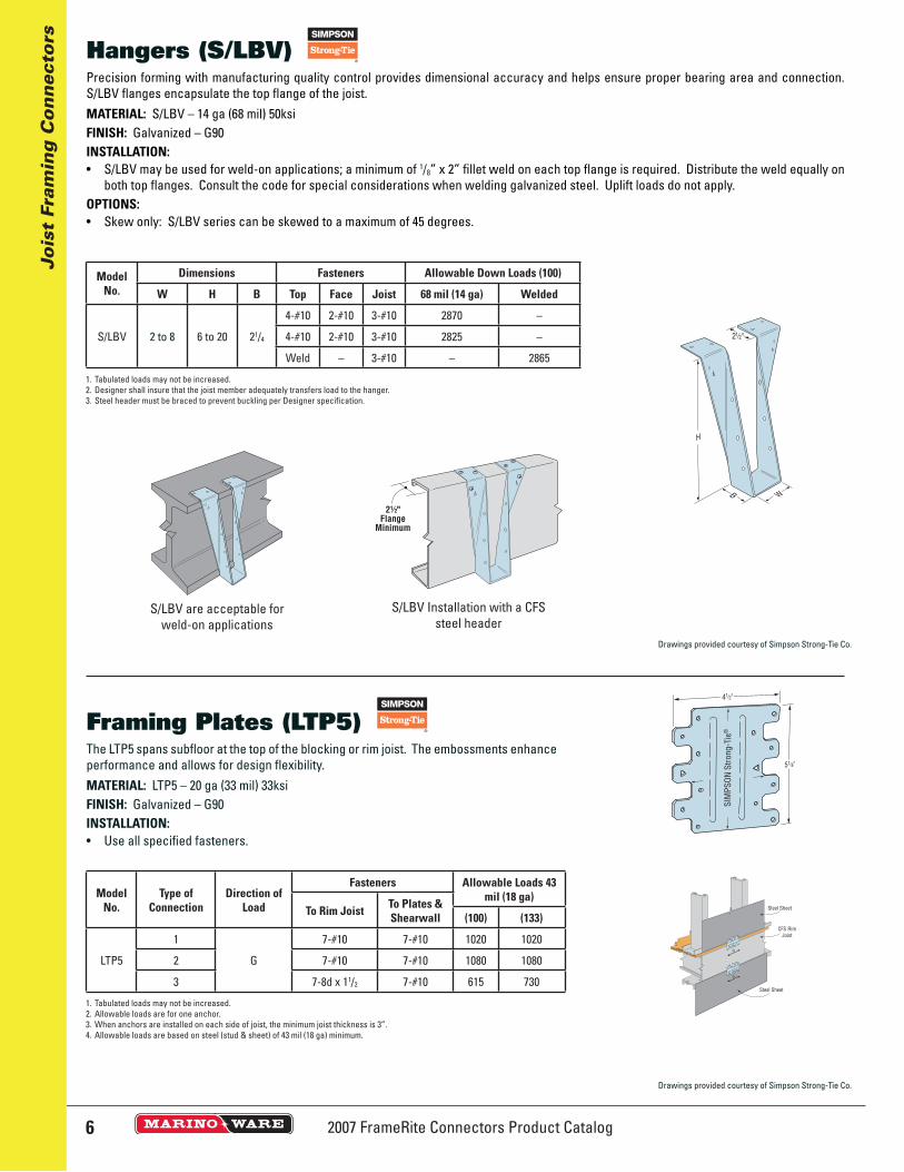
The LTP5 spans subfl oor at the top of the blocking or rim joist. The embossments enhance performance and allows for design fl exibility.MATERIAL: LTP5 – 20 ga (33 mil) 33ksiFINISH: Galvanized – G90INSTALLATION:• Use all specifi ed fasteners.
Framing Plates (LTP5)
ModelNo.
Type ofConnection
Direction of Load
Fasteners Allowable Loads 43 mil (18 ga)
To Rim Joist To Plates & Shearwall (100) (133)
LTP5
1
G
7-#10 7-#10 1020 1020
2 7-#10 7-#10 1080 1080
3 7-8d x 11/2 7-#10 615 730
1. Tabulated loads may not be increased.2. Allowable loads are for one anchor.3. When anchors are installed on each side of joist, the minimum joist thickness is 3”.4. Allowable loads are based on steel (stud & sheet) of 43 mil (18 ga) minimum.
Precision forming with manufacturing quality control provides dimensional accuracy and helps ensure proper bearing area and connection. S/LBV fl anges encapsulate the top fl ange of the joist.MATERIAL: S/LBV – 14 ga (68 mil) 50ksiFINISH: Galvanized – G90INSTALLATION:• S/LBV may be used for weld-on applications; a minimum of 1/8” x 2” fi llet weld on each top fl ange is required. Distribute the weld equally on
both top fl anges. Consult the code for special considerations when welding galvanized steel. Uplift loads do not apply.OPTIONS:• Skew only: S/LBV series can be skewed to a maximum of 45 degrees.
Hangers (S/LBV)
ModelNo.
Dimensions Fasteners Allowable Down Loads (100)
W H B Top Face Joist 68 mil (14 ga) Welded
S/LBV 2 to 8 6 to 20 21/4
4-#10 2-#10 3-#10 2870 –
4-#10 2-#10 3-#10 2825 –
Weld – 3-#10 – 2865
1. Tabulated loads may not be increased. 2. Designer shall insure that the joist member adequately transfers load to the hanger.3. Steel header must be braced to prevent buckling per Designer specifi cation.
2½"Flange
Minimum
S/LBV Installation with a CFS steel header
S/LBV are acceptable for weld-on applications
Drawings provided courtesy of Simpson Strong-Tie Co.
Drawings provided courtesy of Simpson Strong-Tie Co.
72007 FrameRite Connectors Product Catalog
Jois
t Fr
amin
g C
on
nec
tors
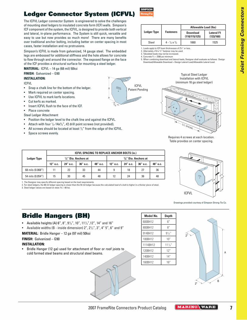
The ICFVL Ledger connector System is engineered to solve the challenges of mounting steel ledgers to insulated concrete form (ICF) walls. Simpson’s ICF component of the system, the ICFVL, is designed to provide both vertical and lateral, in-plane performance. The System is still quick, versatile and easy to use but now provides so much more! There are many benefi ts over traditional anchor bolting, including better on center spacing in most cases, faster installation and no protrusions.Simpson’s ICFVL is made from galvanized, 14 gauge steel. The embedded legs are embossed for additional stiffness and the hole allows for concrete to fl ow through and around the connector. The exposed fl ange on the face of the ICF provides a structural surface for mounting a steel ledger.MATERIAL: ICFVL – 14 ga (68 mil) 50ksiFINISH: Galvanized – G90INSTALLATION:ICFVL• Snap a chalk line for the bottom of the ledger.• Mark required on center spacing.• Use ICFVL to mark kerfs locations.• Cut kerfs as marked.• Insert ICFVL fl ush to the face of the ICF.• Place concreteSteel Ledger Attachment• Position the ledger level to the chalk line and against the ICFVL.• Attach with four 1/4-14x3/4”, #2 drill point screws (not provided).• All screws should be located at least 1/2” from the edge of the ICFVL.• Space screws evenly.
Ledger Connector System (ICFVL)
Ledger Type FastenersAllowable Load (lbs)
Download(110/115/125)
Lateral F1 (133/160)
Steel 4 - 1/4 x 3/4 1660 1525
1. Loads apply to ICF foam thicknesses of 25/8” or less.. 2. Alternately, #14 x 3/4” fastener may be used.3. Tabulated loads may not be increased.4. Concrete f’c = 2500 psi minimum5. When combining download and lateral loads, Designer shall evaluate as follows: Design
Download/Allowable Download + Design Lateral Load/Allowable Lateral Load.
Ledger Type
ICFVL SPACING TO REPLACE ANCHOR BOLTS (in.)1/2” Dia. Anchors at 5/8” Dia. Anchors at
12” o.c. 24” o.c. 36” o.c. 48” o.c. 12” o.c. 24” o.c. 36” o.c. 48” o.c.
68 mils (0.068”) 11 22 33 44 9 18 27 36
54 mils (0.054”) 15 30 45 48 12 24 36 48
1. The Designer may specify different spacing based on the load requirements. 2. For steel ledgers, the 68 mil ledger spacing is closer than the 54 mil ledger because the calculated load of a bolt is higher in a thicker piece of steel.3. Steel ledger values are based on steel. Fu = 60 ksi.
Typical Steel LedgerInstallation with ICFVL
(minimum 16 ga steel ledger)ICFVL
Patent Pending
ICFVL
Requires 4 screws at each location. Table provides on center spacing.
Drawings provided courtesy of Simpson Strong-Tie Co.
• Available heights (A) 6”, 8”, 91/4”, 10”, 111/4”,12”, 14” and 16”• Available widths (B - inside dimension) 2”, 21/2”, 3”, 4” 5”, 6” and 9”MATERIAL: Bridle Hanger – 12 ga (97 mil) 50ksiFINISH: Galvanized – G90INSTALLATION:• Bridle Hanger (12 ga) used for attachment of fl oor or roof joists to
cold formed steel beams and structural steel beams.
Bridle Hangers (BH) Model No. Depth
600BH12 6”
800BH12 8”
914BH12 91/4”
100BH12 10”
1114BH12 111/4”
120BH12 12”
140BH12 14”
160BH12 16”
2007 FrameRite Connectors Product Catalog8
Jois
t Fr
amin
g C
on
nec
tors
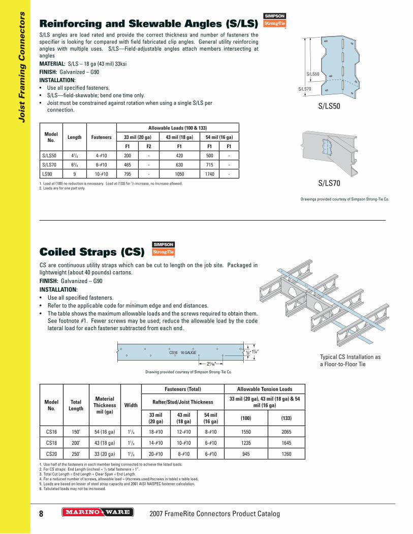
S/LS angles are load rated and provide the correct thickness and number of fasteners the specifi er is looking for compared with fi eld fabricated clip angles. General utility reinforcing angles with multiple uses. S/LS—Field-adjustable angles attach members intersecting at anglesMATERIAL: S/LS – 18 ga (43 mil) 33ksiFINISH: Galvanized – G90INSTALLATION:• Use all specifi ed fasteners.• S/LS—fi eld-skewable; bend one time only.• Joist must be constrained against rotation when using a single S/LS per
connection.
Reinforcing and Skewable Angles (S/LS)
ModelNo. Length Fasteners
Allowable Loads (100 & 133)
33 mil (20 ga) 43 mil (18 ga) 54 mil (16 ga)
F1 F2 F1 F1 F1
S/LS50 47/8 4-#10 200 - 420 500 -
S/LS70 63/8 6-#10 465 - 630 715 -
LS90 9 10-#10 795 - 1050 1740 -
1. Load at (100) no reduction is necessary. Load at (133) for 1/3 increase, no increase allowed.2. Loads are for one part only.
S/LS70
S/LS50
CS are continuous utility straps which can be cut to length on the job site. Packaged in lightweight (about 40 pounds) cartons.FINISH: Galvanized – G90INSTALLATION:• Use all specifi ed fasteners.• Refer to the applicable code for minimum edge and end distances.• The table shows the maximum allowable loads and the screws required to obtain them.
See footnote #1. Fewer screws may be used; reduce the allowable load by the code lateral load for each fastener subtracted from each end.
Coiled Straps (CS)
ModelNo.
Total Length
MaterialThickness
mil (ga)Width
Fasteners (Total) Allowable Tension Loads
Rafter/Stud/Joist Thickness 33 mil (20 ga), 43 mil (18 ga) & 54 mil (16 ga)
33 mil(20 ga)
43 mil (18 ga)
54 mil (16 ga) (100) (133)
CS16 150’ 54 (16 ga) 11/4 18-#10 12-#10 8-#10 1550 2065
CS18 200’ 43 (18 ga) 11/4 14-#10 10-#10 6-#10 1235 1645
CS20 250’ 33 (20 ga) 11/4 20-#10 8-#10 6-#10 945 1260
1. Use half of the fasteners in each member being connected to achieve the listed loads. 2. For CS straps: End Length (inches) = 1/2 total fasteners + 1”.3. Total Cut Length = End Length + Clear Span + End Length.4. For a reduced number of screws, allowable load = (#screws used/#screws in table) x table load.5. Loads are based on lesser of steel strap capacity and 2001 AISI NASPEC fastener calculation.6. Tabulated loads may not be increased.
Typical CS Installation as a Floor-to-Floor Tie
Drawings provided courtesy of Simpson Strong-Tie Co.
Drawing provided courtesy of Simpson Strong-Tie Co.
92007 FrameRite Connectors Product Catalog
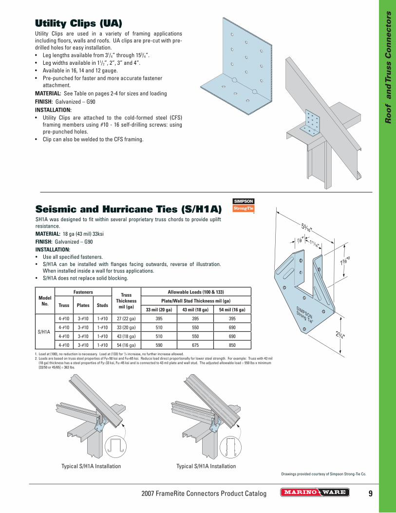
SH1A was designed to fi t within several proprietary truss chords to provide uplift resistance.MATERIAL: 18 ga (43 mil) 33ksiFINISH: Galvanized – G90INSTALLATION:• Use all specifi ed fasteners.• S/H1A can be installed with fl anges facing outwards, reverse of illustration.
When installed inside a wall for truss applications.• S/H1A does not replace solid blocking.
Seismic and Hurricane Ties (S/H1A)
ModelNo.
Fasteners Truss Thickness
mil (ga)
Allowable Loads (100 & 133)
Truss Plates StudsPlate/Wall Stud Thickness mil (ga)
33 mil (20 ga) 43 mil (18 ga) 54 mil (16 ga)
S/H1A
4-#10 3-#10 1-#10 27 (22 ga) 395 395 395
4-#10 3-#10 1-#10 33 (20 ga) 510 550 690
4-#10 3-#10 1-#10 43 (18 ga) 510 550 690
4-#10 3-#10 1-#10 54 (16 ga) 590 675 850
1. Load at (100), no reduction is necessary. Load at (133) for 1/3 increase, no further increase allowed.2. Loads are based on truss steel properties of Fy=50 ksi and Fu=65 ksi. Reduce load direct proportionally for lower steel strength. For example: Truss with 43 mil
(18 ga) thickness has a steel properties of Fy=33 ksi, Fu=45 ksi and is connected to 43 mil plate and wall stud. The adjusted allowable load = 550 lbs x minimum [33/50 or 45/65] = 363 lbs.
1⁵⁄₈"⁰
⁷⁄₈"
5⁵⁄₁₆"
2³⁄₄"
1¹¹⁄₁₆"
Typical S/H1A Installation Typical S/H1A Installation
Ro
of
an
d T
russ
Co
nn
ecto
rs
Utility Clips are used in a variety of framing applications including fl oors, walls and roofs. UA clips are pre-cut with pre-drilled holes for easy installation.• Leg lengths available from 31/4” through 153/4”.• Leg widths available in 11/2”, 2”, 3” and 4”.• Available in 16, 14 and 12 gauge. • Pre-punched for faster and more accurate fastener
attachment.MATERIAL: See Table on pages 2-4 for sizes and loadingFINISH: Galvanized – G90INSTALLATION:• Utility Clips are attached to the cold-formed steel (CFS)
framing members using #10 - 16 self-drilling screws: using pre-punched holes.
• Clip can also be welded to the CFS framing.
Utility Clips (UA)
Drawings provided courtesy of Simpson Strong-Tie Co.
2007 FrameRite Connectors Product Catalog10
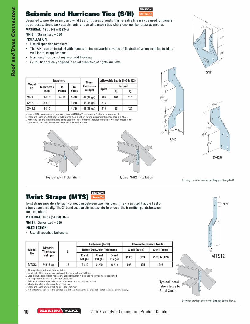
Twist straps provide a tension connection between two members. They resist uplift at the heel of a truss economically. The 3” bend section eliminates interference at the transition points between steel members.MATERIAL: 16 ga (54 mil) 50ksiFINISH: Galvanized – G90INSTALLATION:• Use all specifi ed fasteners.
Twist Straps (MTS)
ModelNo.
MaterialThickness
mil (ga)L
Fasteners (Total) Allowable Tension Loads
Rafter/Stud/Joist Thickness 33 mil (20 ga) 43 mil (18 ga)
33 mil(20 ga)
43 mil (18 ga)
54 mil(16 ga) (100) (133) (100) & (133)
MTS12 54 (16 ga) 12 12-#10 8-#10 6-#10 995 995 995
1. All straps have additional fastener holes. 2. Install half of the fasteners on each end of strap to achieve full loads.3. Load at (100), no reduction necessary. Load at (133) for 1/3 increase, no further increase allowed.4. All straps have the twist in the center of the strap.5. Twist straps do not have to be wrapped over the truss to achieve the load.6. May be installed on the inside face of the stud.7. Loads are based on steel with 43 mil (18 ga) minimum.8. Not all fastener holes need to be fi lled as additional fastener holes provided. Install fasteners symmetrically.
MTS12
1" TYP
L
1¹⁄₄"
SIM
PS
ON
Stro
ng-T
ie®
Typical Instal-lation Truss to Steel Studs
Designed to provide seismic and wind ties for trusses or joists, this versatile line may be used for general tie purposes, strongback attachments, and as all-purpose ties where one member crosses another.MATERIAL: 18 ga (43 mil) 33ksiFINISH: Galvanized – G90INSTALLATION:• Use all specifi ed fasteners.• The S/H1 can be installed with fl anges facing outwards (reverse of illustration) when installed inside a
wall for truss applications.• Hurricane Ties do not replace solid blocking• S/H2.5 ties are only shipped in equal quantities of rights and lefts.
Seismic and Hurricane Ties (S/H)
ModelNo.
Fasteners Truss Thickness
mil (ga)
Allowable Loads (100 & 133)
To Rafters / Truss
To Plates
To Studs Uplift
Lateral
F1 F2
S/H1 3-#10 2-#10 1-#10 43 (18 ga) 265 100 115
S/H2 3-#10 3-#10 43 (18 ga) 315
S/H2.5 4-#10 4-#10 43 (18 ga) 415 90 125
1. Load at (100), no reduction is necessary. Load at (133) for 1/3 increase, no further increase allowed.2. Loads are based on attachment of cold-formed steel members having a minimum thickness of 33 mil (20 ga).3. Hurricane Ties are shown installed on the outside of wall for clarity. Installation inside of wall is acceptable. For
Continuous Load Path, connections must be on same side of wall.
Typical S/H2 InstallationTypical S/H1 Installation
S/H2
S/H2.5
S/H1
Ro
of
and
Tru
ss C
on
nec
tors
Drawings provided courtesy of Simpson Strong-Tie Co.
Drawings provided courtesy of Simpson Strong-Tie Co.

11 2007 FrameRite Connectors Product Catalog
S/MST
ST
Straps are load rated and provide the correct thickness and number of fasteners the specifier is looking for compared with the field fabricated straps.Install Strap Ties where top or bottom plates are cut, at wall intersections, and as ridge ties. LSTA and MSTA straps are engineered for use on members with a minimum width of 11/2”. Reduce the allowable load based on the size and quantity of fasteners used.Refer to applicable code for minimum edge and end distances.FINISH: Galvanized – G90INSTALLATION:• Use all specified fasteners.
LSTA and MSTA
Strap Ties (ST/LSTA/MST/MSTA)
Model No.Material
Thickness mil (ga)
DimensionsFasteners (Total) Allowable Tension Loads
Rafter/Stud/Joist Thickness 33 mil (20 ga) 43 mil (18 ga) 54 mil (16 ga)
W L 33 mil(20 ga)
43 mil (18 ga)
54 mil (16 ga) (100) (133) (100) (133) (100) (133)
LSTA24 33 (20 ga) 11/4 24 14-#10 12-#10 10-#10 1190 1590 1190 1590 1190 1590
LSTA36 43 (18 ga) 11/4 36 18-#10 16-#10 14-#10 1555 2070 1555 2070 1555 2070
MSTA24 43 (18 ga) 11/4 24 18-#10 12-#10 10-#10 1555 2070 1555 2070 1555 070
MSTA36 54 (16 ga) 11/4 36 24-#10 18-#10 16-#10 1950 2600 1950 2600 1950 2600
ST6224 54 (16 ga) 21/16 235/16 28-#10 20-#10 12-#10 2455 3275 2455 3275 2455 3275
ST6236 68 (14 g) 21/16 3313/16 40-#10 30-#10 18-#10 3535 4715 3760 5015 3760 5015
MST27 97 (12 ga) 21/16 27 30-#10 30-#10 22-#10 2650 3535 3945 5260 5025 6700
MST37 97 (12 ga) 21/16 371/2 40-#10 40-#10 22-#10 3710 4950 5025 6700 5025 6700
1. Use half of the fasteners in each member being connected to achieve the listed loads.2. Loads are based on lesser of steel capacity and fastener calculation.3. Tabulated loads may not be increased.
Ro
of
and
Tru
ss C
on
nec
tors
Drawings provided courtesy of Simpson Strong-Tie Co.

2007 FrameRite Connectors Product Catalog12
Ro
of
and
Tru
ss C
on
nec
tors
Designed for a variety of construction connections. Used for conditions such as roof, wall and floor framing connections. GPU Plate is used for in plane Truss chord connections, Header to jamb connections and Tension Strap connections. Adapts to varying construction tolerances.MATERIAL: See Table, 50ksiFINISH: Galvanized coating weight as requested.INSTALLATION:• As specified by design.• 16 Gauge (54 mils) .0566” Design Thickness• 12 Gauge (97 mils) .1017” Design Thickness• Custom sizes available upon request.
Gusset Plate (Unpunched) (GP)
Model No. Thickness Gauge Size
GPU66-16 16 6x6
GPU612-16 16 6x12
GPU1212-16 16 12x12
GPU66-12 12 6x6
GPU612-12 12 6x12
GPU1212-12 12 12x12
Katz Blocking has been designed to provide top of wall attachment between parallel framing members. Product is pre-punched to work in 16” and 24” spacing of parallel framing members of wood or steel.MATERIAL: See Table. 18 ga (43 mil) 33ksi; 20 ga (30 mil) 33ksi; 25 ga (18 mil) 33ksiFINISH: Galvanized – G40INSTALLATION:• Insert the pre-cut structural blocking to fit securely between the underside of
the floor/ceiling joist or roof trusses.• Using #8 minimum self-drilling screws secure the blocking to steel framing or
#8d nail to wood framing using the pre-punched holes.• Use Katz blocking at 4’ o.c. or maximum specified.
Katz Blocking (KB)
16” or 24”
35/8”11/4”
Model No. Length Gauge Size Pallet Quantity
KATZ16 16” 25 35/8” 500
KATZ24 24” 25 35/8” 500
KATZ2024 24” 20 35/8” 500
KATZ1816 16” 18 35/8” 200
KATZ1824 24” 18 35/8” 200NEW
13 2007 FrameRite Connectors Product Catalog
Rig
id C
on
nec
tors
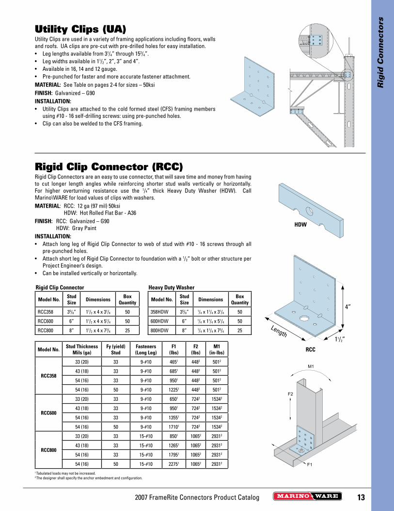
Utility Clips are used in a variety of framing applications including floors, walls and roofs. UA clips are pre-cut with pre-drilled holes for easy installation.• Leg lengths available from 31/4” through 153/4”.• Leg widths available in 11/2”, 2”, 3” and 4”.• Available in 16, 14 and 12 gauge. • Pre-punched for faster and more accurate fastener attachment.MATERIAL: See Table on pages 2-4 for sizes – 50ksiFINISH: Galvanized – G90INSTALLATION:• Utility Clips are attached to the cold formed steel (CFS) framing members
using #10 - 16 self-drilling screws: using pre-punched holes. • Clip can also be welded to the CFS framing.
Utility Clips (UA)
Rigid Clip Connectors are an easy to use connector, that will save time and money from having to cut longer length angles while reinforcing shorter stud walls vertically or horizontally. For higher overturning resistance use the 1/4” thick Heavy Duty Washer (HDW). Call Marino\WARE for load values of clips with washers.MATERIAL: RCC: 12 ga (97 mil) 50ksi HDW: Hot Rolled Flat Bar - A36FINISH: RCC: Galvanized – G90 HDW: Gray PaintINSTALLATION:• Attach long leg of Rigid Clip Connector to web of stud with #10 - 16 screws through all
pre-punched holes.• Attach short leg of Rigid Clip Connector to foundation with a 1/2“ bolt or other structure per
Project Engineer’s design.• Can be installed vertically or horizontally.
Rigid Clip Connector (RCC)
Model No. Stud Size Dimensions Box
Quantity
RCC358 35/8” 11/2 x 4 x 31/4 50
RCC600 6” 11/2 x 4 x 51/4 50
RCC800 8” 11/2 x 4 x 73/4 25
Model No. Stud Thickness Mils (ga)
Fy (yield) Stud
Fasteners(Long Leg)
F1(lbs)
F2(lbs)
M1(in-lbs)
RCC358
33 (20) 33 9-#10 4651 4482 5012
43 (18) 33 9-#10 6851 4482 5012
54 (16) 33 9-#10 9501 4482 5012
54 (16) 50 9-#10 12251 4482 5012
RCC600
33 (20) 33 9-#10 6501 7242 15342
43 (18) 33 9-#10 9501 7242 15342
54 (16) 33 9-#10 13551 7242 15342
54 (16) 50 9-#10 17101 7242 15342
RCC800
33 (20) 33 15-#10 8501 10652 29312
43 (18) 33 15-#10 12651 10652 29312
54 (16) 33 15-#10 17951 10652 29312
54 (16) 50 15-#10 22751 10652 29312
1 Tabulated loads may not be increased.2 The designer shall specify the anchor embedment and configuration.
Model No. Stud Size Dimensions Box
Quantity
358HDW 35/8” 1/4 x 11/4 x 31/4 50
600HDW 6” 1/4 x 11/4 x 51/4 50
800HDW 8” 1/4 x 11/4 x 73/4 25
Rigid Clip Connector Heavy Duty Washer
4”
11/2”
Length
HDW
RCC

2007 FrameRite Connectors Product Catalog14
Rig
id C
on
nec
tors
MATERIAL: S/HD8 and S/HD10 – 118 mil (10 ga) with 3/8” plate, S/HD15 – 171 mil (7 ga) with 1/2” plate.
FINISH: Simpson gray paint. Hot-dip galvanized is available.INSTALLATION:• Use all specifi ed fasteners.• The design engineer may specify any alternate anchorage calculated
to resist the tension load for your specifi c job.• Anchor bolt washer is not required.
Holdowns (S/HD)
ModelNo.
Dimensions Fasteners Allowable Tension Loads (133) HoldownDefl ection at Highest
Allowable Design Load
W H CL AnchorDia Screws 2–33 mil
(2–20ga)43 mil (18
ga)54 mil (16
ga)
S/HD8 21/2 137/8 11/27/8 24-#10 7615 8460 8940 0.085
S/HD10 21/2 161/8 11/27/8 30-#10 9520 9665 9665 0.093
S/HD15 23/4 211/2 11/2 1 48-#10 – 12200 14405 0.070
1. For load at (100), multiply table value by 0.75 where the 1/3 increase is not permitted.2. Values are test limited. For load at (100), no reduction necessary. For load at (133) for 1/3 increase, no further increase allowed.3. The Designer shall specify the anchor embedment and confi guration. 4. Defl ection at Highest allowable Design Load: The defl ection of a holdown measured between the anchor bolt and the strap portion of the holdown when loaded to the
highest allowable load listed in the catalog table. This movement is strictly due to the holdown deformation under a static load test conducted on a steel jig.
2³⁄₄" (S/HD10)2³⁄₈" (S/HD15)
The S/HTT14 is a single-piece formed tension tie–no rivets, and a 4-ply formed seat which won’t unfold during loading. No washers are required.The S/LTT and S/HTT Tension Ties are ideal for retrofi t or new con-struction projects. They provide high strength, post-pour, concrete-to-steel connections.MATERIAL: See table.FINISH: Galvanized – G90INSTALLATION:• Use all specifi ed fasteners.• Use the specifi ed number and type of screws to attach the strap
portion to the steel stud. Bolt the base to the wall or foundation with a suitable anchor; see table for the required bolt diameter.
Tension Ties (S/LTT and S/HTT)
Model No.Material mil (ga) Dimensions Fasteners
AllowableTension
Loads (133)Holdown
Defl ection at Highest Allowable Design
LoadStrap Plate W H CL AnchorBolts Screws 2–33 mil
(2–20ga)
S/LTT20 97 (12 ga) 229 (3 ga) 2 20 11/21/2 5-#10 1600 0.209
S/HTT14 111 (11 ga) – 21/2 15 11/45/8 14-#10 4385 0.041
1. The Designer shall specify the anchor embedment and confi guration. 2. Load at (100), no reduction necessary. Load at (133) for 1/3 increase, no further increase allowed.3. Loads are based on attachment of CFS members having a minimum thickness of 33 mil (20 ga).4. Defl ection at Highest allowable Design Load: The defl ection of a holdown measured between the anchor bolt and the strap portion of the holdown when loaded to the highest
allowable load listed in the catalog table. This movement is strictly due to the holdown deformation under a static load test conducted on a steel jig.
S/LTT20
S/HTT14
23/4 SHD8, S/HD1023/8 S/HD15
Drawings provided courtesy of Simpson Strong-Tie Co.
Drawings provided courtesy of Simpson Strong-Tie Co.
152007 FrameRite Connectors Product Catalog
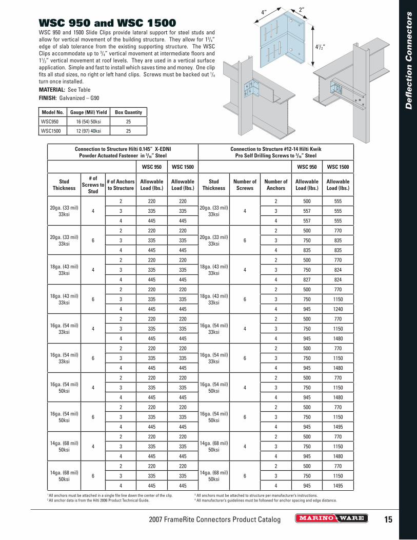
WSC 950 and 1500 Slide Clips provide lateral support for steel studs and allow for vertical movement of the building structure. They allow for 13/4”edge of slab tolerance from the existing supporting structure. The WSC Clips accommodate up to 3/4” vertical movement at intermediate fl oors and 11/2” vertical movement at roof levels. They are used in a vertical surface application. Simple and fast to install which saves time and money. One clip fi ts all stud sizes, no right or left hand clips. Screws must be backed out 1/4
turn once installed.MATERIAL: See TableFINISH: Galvanized – G90
WSC 950 and WSC 1500
Model No. Gauge (Mil) Yield Box Quantity
WSC950 16 (54) 50ksi 25
WSC1500 12 (97) 40ksi 25
41/2”
4” 2”
Defl
ect
ion
Co
nn
ecto
rs
Connection to Structure Hilti 0.145” X-EDNI Powder Actuated Fastener in 3/16” Steel
Connection to Structure #12-14 Hilti Kwik Pro Self Drilling Screws to 3/16” Steel
WSC 950 WSC 1500 WSC 950 WSC 1500
StudThickness
# of Screws to
Stud
# of Anchors to Structure
AllowableLoad (lbs.)
AllowableLoad (lbs.)
StudThickness
Number of Screws
Number of Anchors
AllowableLoad (lbs.)
AllowableLoad (lbs.)
20ga. (33 mil) 33ksi 4
2 220 22020ga. (33 mil)
33ksi 4
2 500 555
3 335 335 3 557 555
4 445 445 4 557 555
20ga. (33 mil) 33ksi 6
2 220 22020ga. (33 mil)
33ksi 6
2 500 770
3 335 335 3 750 835
4 445 445 4 835 835
18ga. (43 mil) 33ksi 4
2 220 22018ga. (43 mil)
33ksi 4
2 500 770
3 335 335 3 750 824
4 445 445 4 827 824
18ga. (43 mil) 33ksi 6
2 220 22018ga. (43 mil)
33ksi 6
2 500 770
3 335 335 3 750 1150
4 445 445 4 945 1240
16ga. (54 mil) 33ksi 4
2 220 22016ga. (54 mil)
33ksi 4
2 500 770
3 335 335 3 750 1150
4 445 445 4 945 1480
16ga. (54 mil) 33ksi 6
2 220 22016ga. (54 mil)
33ksi 6
2 500 770
3 335 335 3 750 1150
4 445 445 4 945 1480
16ga. (54 mil) 50ksi 4
2 220 22016ga. (54 mil)
50ksi 4
2 500 770
3 335 335 3 750 1150
4 445 445 4 945 1480
16ga. (54 mil) 50ksi 6
2 220 22016ga. (54 mil)
50ksi 6
2 500 770
3 335 335 3 750 1150
4 445 445 4 945 1495
14ga. (68 mil) 50ksi 4
2 220 22014ga. (68 mil)
50ksi 4
2 500 770
3 335 335 3 750 1150
4 445 445 4 945 1480
14ga. (68 mil) 50ksi 6
2 220 22014ga. (68 mil)
50ksi 6
2 500 770
3 335 335 3 750 1150
4 445 445 4 945 14951 All anchors must be attached in a single fi le line down the center of the clip. 3 All anchors must be attached to structure per manufacturer’s instructions.2 All anchor data is from the Hilti 2006 Product Technical Guide. 4 All manufacturer’s guidelines must be followed for anchor spacing and edge distance.
2007 FrameRite Connectors Product Catalog16
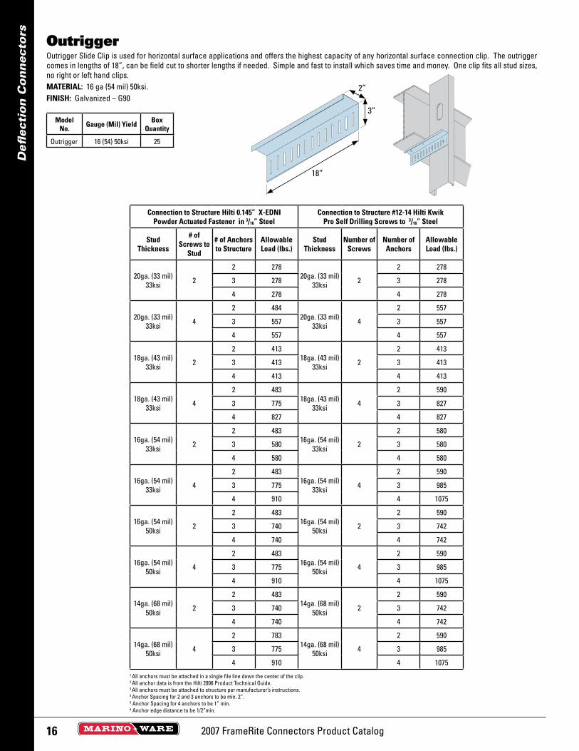
Outrigger Slide Clip is used for horizontal surface applications and offers the highest capacity of any horizontal surface connection clip. The outrigger comes in lengths of 18”, can be field cut to shorter lengths if needed. Simple and fast to install which saves time and money. One clip fits all stud sizes, no right or left hand clips.MATERIAL: 16 ga (54 mil) 50ksi.FINISH: Galvanized – G90
Outrigger
2”
3”
18”
Model No. Gauge (Mil) Yield Box
Quantity
Outrigger 16 (54) 50ksi 25
Defl
ecti
on
Co
nn
ecto
rs
Connection to Structure Hilti 0.145” X-EDNI Powder Actuated Fastener in 3/16” Steel
Connection to Structure #12-14 Hilti Kwik Pro Self Drilling Screws to 3/16” Steel
Stud Thickness
# of Screws to
Stud
# of Anchors to Structure
Allowable Load (lbs.)
Stud Thickness
Number of Screws
Number of Anchors
Allowable Load (lbs.)
20ga. (33 mil) 33ksi 2
2 27820ga. (33 mil)
33ksi 2
2 278
3 278 3 278
4 278 4 278
20ga. (33 mil) 33ksi 4
2 48420ga. (33 mil)
33ksi 4
2 557
3 557 3 557
4 557 4 557
18ga. (43 mil) 33ksi 2
2 41318ga. (43 mil)
33ksi 2
2 413
3 413 3 413
4 413 4 413
18ga. (43 mil) 33ksi 4
2 48318ga. (43 mil)
33ksi 4
2 590
3 775 3 827
4 827 4 827
16ga. (54 mil) 33ksi 2
2 48316ga. (54 mil)
33ksi 2
2 580
3 580 3 580
4 580 4 580
16ga. (54 mil) 33ksi 4
2 48316ga. (54 mil)
33ksi 4
2 590
3 775 3 985
4 910 4 1075
16ga. (54 mil) 50ksi 2
2 48316ga. (54 mil)
50ksi 2
2 590
3 740 3 742
4 740 4 742
16ga. (54 mil) 50ksi 4
2 48316ga. (54 mil)
50ksi 4
2 590
3 775 3 985
4 910 4 1075
14ga. (68 mil) 50ksi 2
2 48314ga. (68 mil)
50ksi 2
2 590
3 740 3 742
4 740 4 742
14ga. (68 mil) 50ksi 4
2 78314ga. (68 mil)
50ksi 4
2 590
3 775 3 985
4 910 4 10751 All anchors must be attached in a single file line down the center of the clip.2 All anchor data is from the Hilti 2006 Product Technical Guide.3 All anchors must be attached to structure per manufacturer’s instructions.4 Anchor Spacing for 2 and 3 anchors to be min. 2”.5 Anchor Spacing for 4 anchors to be 1” min.6 Anchor edge distance to be 1/2”min.

172007 FrameRite Connectors Product Catalog
Model No. Gauge (Mil) Yield Box Quantity
3T1000 16 (54) 50ksi 25
6T1000 16 (54) 50ksi 25
The Defl ex Slide Clips allow for up to 11/2” vertical fl oor or roof defl ection without the use of laborious slip tracks it can be installed with or without standard leg tracks. Simple and fast to install which saves time and money. Two sizes available for 35/8”, 4”, 6” and 8” studs.MATERIAL: 16 ga (54 mil) 50ksi.FINISH: Galvanized – G90• 3T1000 accommodates 3 5/8” and 4” stud widths• 6T1000 accommodates 6” and 8” stud widths
Defl ex
11/2” 2 7/8 ” or 5 1/
4 ”
41/2”
Defl
ect
ion
Co
nn
ecto
rs
Connection to Structure Hilti 0.145” X-EDNI Powder Actuated Fastener in 3/16” Steel
Connection to Structure #12-14 Hilti Kwik Pro Self Drilling Screws to 3/16” Steel
Defl ex 3T1000 Defl ex 6T1000 Defl ex 3T1000 Defl ex 6T1000
StudThickness
# of Screws to
Stud
# of Anchors to Structure
AllowableLoad (lbs.)
AllowableLoad (lbs.)
StudThickness
Number of Screws
Number of Anchors
AllowableLoad (lbs.)
AllowableLoad (lbs.)
20ga. (33 mil) 33ksi 2
2 224 276 20ga. (33 mil) 33ksi 2
2 278 278
3 228 276 3 278 278
18ga. (43 mil) 33ksi 2
2 224 413 18ga. (43 mil) 33ksi 2
2 410 413
3 228 413 3 410 413
16ga. (54 mil) 33ksi 2
2 224 413 16ga. (54 mil) 33ksi 2
2 455 580
3 228 440 3 495 580
16ga. (54 mil) 50ksi 2
2 224 413 16ga. (54 mil) 50ksi 2
2 455 685
3 228 440 3 495 742
14ga. (68 mil) 50ksi 2
2 224 413 14ga. (68 mil) 50ksi 2
2 455 685
3 228 440 3 495 7421 All anchors must be attached in a single fi le line down the center of the clip.2 All anchor data is from the Hilti 2006 Product Technical Guide.3 All anchors must be attached to structure per manufacturer’s instructions.4 Anchor edge distance to be 1/2” min.

2007 FrameRite Connectors Product Catalog18
Defl
ecti
on
Co
nn
ecto
rs
Marino\WARE Model No.
SectionDesignation Mil (ga)
Track Member
WidthFlange
212SLT2010 250CST250-30 33 (20 ga) 21/2” 21/2”
358SLT1610 362CST250-54 54 (16 ga) 35/8” 21/2”
358SLT1810 362CST250-43 43 (18 ga) 35/8” 21/2”
358SLT2010 362CST250-30 33 (20 ga) 35/8” 21/2”
400SLT1610 400CST250-54 54 (16 ga) 4” 21/2”
400SLT1810 400CST250-43 43 (18 ga) 4” 21/2”
400SLT2010 400CST250-30 33 (20 ga) 4” 21/2”
600SLT1610 600CST250-54 54 (16 ga) 6” 21/2”
600SLT1810 600CST250-43 43 (18 ga) 6” 21/2”
600SLT2010 600CST250-33 33 (20 ga) 6” 21/2”
800SLT1610 800CST250-54 54 (16 ga) 8” 21/2”
800SLT1810 800CST250-43 43 (18 ga) 8” 21/2”
800SLT2010 800CST250-33 33 (20 ga) 8” 21/2”
Slotted Slip Track (SLT) member is used as vertical deflection track in interior non bearing wall assemblies. The U-shape track has 11/2” vertical slots spaced 1” along both legs. The track section is fabricated from hot-dipped galvanized steel complying with ASTM A653, with a minimum G40 coating. The framing members comply with ASTM C645.
MATERIAL: 20 ga (30 and 33 mil), 18 ga (43 mil), and 16 ga (54 mil) 33ksi
TRACK MEMBER DEPTH (Inches): 21/2”, 35/8”, 4”, 6”, and 8”
FINISH: Galvanized – 20 ga - G40; 18 ga and 16 ga - G60• One-piece design• Positive attachment to framing• Absorbs vertical deflection• Simple Installation and Reduced Labor Time
Slotted Slip Track (SLT) NEW
SectionDesignation
Design Thickness
(inch)
Gross Section Properties Effective Section Properties
Fy(ksi)
Weight(lbs/ft)
Area(in2)
lx(in4)
rx(in)
ly(in4)
ry(in4)
lx(in4)
Sx (t)(in3)
Sx (b)(in3)
ly(in4)
Sy (l)(in3)
Sy (r)(in3)
250CST250-18 0.0188 33 0.267 0.079 0.068 0.927 0.080 1.006 0.055 0.064 0.034 0.054 0.058 0.033
250CST250-30 0.0312 33 0.444 0.131 0.112 0.925 0.133 1.011 0.098 0.126 0.056 0.099 0.096 0.063
250CST250-43 0.0451 33 0.640 0.188 0.160 0.923 0.193 1.012 0.148 0.212 0.082 0.147 0.136 0.096
250CST250-54 0.0566 50 0.802 0.236 0.200 0.922 0.243 1.015 0.186 0.266 0.103 0.186 0.169 0.121
350CST250-18 0.0188 33 0.331 0.097 0.072 0.862 0.176 1.343 0.057 0.069 0.034 0.113 0.091 0.049
350CST250-30 0.0312 33 0.549 0.162 0.120 0.861 0.293 1.346 0.105 0.156 0.057 0.214 0.150 0.099
350CST250-43 0.0451 33 0.793 0.233 0.172 0.859 0.424 1.348 0.160 0.271 0.084 0.334 0.216 0.161
350CST250-54 0.0566 50 0.994 0.292 0.215 0.857 0.533 1.351 0.201 0.340 0.105 0.421 0.269 0.202
362CST250-18 0.0188 33 0.339 0.100 0.073 0.855 0.191 1.384 0.057 0.069 0.034 0.122 0.095 0.051
362CST250-30 0.0312 33 0.562 0.165 0.121 0.853 0.318 1.387 0.105 0.158 0.057 0.232 0.158 0.103
362CST250-43 0.0451 33 0.812 0.239 0.173 0.851 0.461 1.389 1.161 0.279 0.084 0.362 0.226 0.168
362CST250-54 0.0566 50 1.018 0.300 0.216 0.850 0.580 1.391 0.202 0.349 0.105 0.456 0.283 0.212
400CST250-18 0.0188 33 0.363 0.107 0.074 0.834 0.242 1.506 0.057 0.070 0.034 0.151 0.109 0.056
400CST250-30 0.0312 33 0.602 0.177 0.123 0.832 0.403 1.508 0.106 0.162 0.058 0.334 0.182 0.148
400CST250-43 0.0451 33 0.870 0.256 0.176 0.830 0.584 1.511 0.165 0.300 0.084 0.483 0.262 0.212
400CST250-54 0.0566 50 1.090 0.321 0.220 0.829 0.734 1.512 0.206 0.375 0.106 0.607 0.327 0.265
600CST250-18 0.0188 33 0.491 0.144 0.079 0.740 0.658 2.135 0.057 0.071 0.034 0.412 0.191 0.105
600CST250-33 0.0346 33 0.903 0.266 0.145 0.738 1.212 2.136 0.123 0.209 0.064 0.973 0.364 0.284
600CST250-43 0.0451 33 1.176 0.346 0.188 0.737 1.581 2.137 0.170 0.342 0.085 1.365 0.481 0.416
600CST250-54 0.0566 50 1.475 0.434 0.235 0.735 1.985 2.139 0.213 0.431 0.106 1.713 0.601 0.520
800CST250-18 0.0188 33 0.619 0.182 0.082 0.671 1.370 2.743 0.058 0.072 0.034 0.764 0.291 0.140
800CST250-33 0.0346 33 1.138 0.335 0.150 0.669 2.521 2.744 0.124 0.215 0.065 1.792 0.557 0.367
800CST250-43 0.0451 33 1.483 0.436 0.195 0.668 3.286 2.745 0.172 0.362 0.085 2.688 0.742 0.597
800CST250-54 0.0566 50 1.860 0.547 0.243 0.666 4.124 2.746 0.216 0.457 0.107 3.415 0.931 0.763
For SI: 1 inch = 25.4 mm, 1 ksi = 6.8948 kPa, 1 lb/ft = 14.594 N/m.All information shown for Slotted Slip Track provided courtesy of CEMCO.
192007 FrameRite Connectors Product Catalog
Bri
dg
ing
an
d B
raci
ng
Co
nn
ecto
rs
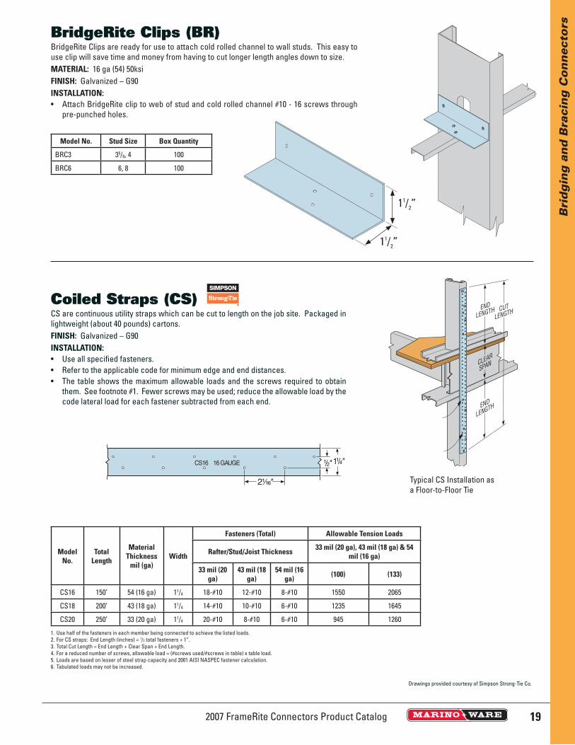
BridgeRite Clips are ready for use to attach cold rolled channel to wall studs. This easy to use clip will save time and money from having to cut longer length angles down to size.MATERIAL: 16 ga (54) 50ksiFINISH: Galvanized – G90 INSTALLATION:• Attach BridgeRite clip to web of stud and cold rolled channel #10 - 16 screws through
pre-punched holes.
BridgeRite Clips (BR)
Model No. Stud Size Box Quantity
BRC3 35/8, 4 100
BRC6 6, 8 100
11/2”
11/2”
CS are continuous utility straps which can be cut to length on the job site. Packaged in lightweight (about 40 pounds) cartons.FINISH: Galvanized – G90INSTALLATION:• Use all specifi ed fasteners.• Refer to the applicable code for minimum edge and end distances.• The table shows the maximum allowable loads and the screws required to obtain
them. See footnote #1. Fewer screws may be used; reduce the allowable load by the code lateral load for each fastener subtracted from each end.
Coiled Straps (CS)
ModelNo.
Total Length
MaterialThickness
mil (ga)Width
Fasteners (Total) Allowable Tension Loads
Rafter/Stud/Joist Thickness 33 mil (20 ga), 43 mil (18 ga) & 54 mil (16 ga)
33 mil (20 ga)
43 mil (18 ga)
54 mil (16 ga) (100) (133)
CS16 150’ 54 (16 ga) 11/4 18-#10 12-#10 8-#10 1550 2065
CS18 200’ 43 (18 ga) 11/4 14-#10 10-#10 6-#10 1235 1645
CS20 250’ 33 (20 ga) 11/4 20-#10 8-#10 6-#10 945 1260
1. Use half of the fasteners in each member being connected to achieve the listed loads. 2. For CS straps: End Length (inches) = 1/2 total fasteners + 1”.3. Total Cut Length = End Length + Clear Span + End Length.4. For a reduced number of screws, allowable load = (#screws used/#screws in table) x table load.5. Loads are based on lesser of steel strap capacity and 2001 AISI NASPEC fastener calculation.6. Tabulated loads may not be increased.
Typical CS Installation as a Floor-to-Floor Tie
Drawings provided courtesy of Simpson Strong-Tie Co.
2007 FrameRite Connectors Product Catalog20
Bri
dg
ing
an
d B
raci
ng
Co
nn
ecto
rs
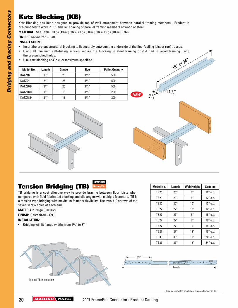
Katz Blocking has been designed to provide top of wall attachment between parallel framing members. Product is pre-punched to work in 16” and 24” spacing of parallel framing members of wood or steel.MATERIAL: See Table. 18 ga (43 mil) 33ksi; 20 ga (30 mil) 33ksi; 25 ga (18 mil) 33ksiFINISH: Galvanized – G40INSTALLATION:• Insert the pre-cut structural blocking to fit securely between the underside of the floor/ceiling joist or roof trusses.• Using #8 minimum self-drilling screws secure the blocking to steel framing or #8d nail to wood framing using
the pre-punched holes.• Use Katz blocking at 4’ o.c. or maximum specified.
Katz Blocking (KB)
16” or 24”
35/8”11/4”
Model No. Length Gauge Size Pallet Quantity
KATZ16 16” 25 35/8” 500
KATZ24 24” 25 35/8” 500
KATZ2024 24” 20 35/8” 500
KATZ1816 16” 18 35/8” 200
KATZ1824 24” 18 35/8” 200
TB bridging is a cost effective way to provide bracing between floor joists when compared with field fabricated blocking and clip angles with multiple fasteners. TB is a tension-type bridging with maximum fastener flexibility. Use two #10 screws of the seven screw holes at each end.MATERIAL: 20 ga (33) 50ksiFINISH: Galvanized – G90 INSTALLATION:• Bridging will fit flange widths from 15/8” to 3”
Tension Bridging (TB) Model No. Length Web Height Spacing
TB20 20” 6” 12” o.c.
TB20 20” 8” 12” o.c.
TB20 20” 10” 12” o.c.
TB27 27” 12” 12” o.c.
TB27 27” 6” 16” o.c.
TB27 27” 8” 16” o.c.
TB27 27” 10” 16” o.c.
TB27 27” 12” 16” o.c.
TB36 36” 10” 24” o.c.
TB36 36” 12” 24” o.c.
Drawings provided courtesy of Simpson Strong-Tie Co.
53/8”
Length
Typical TB Installation
NEW

212007 FrameRite Connectors Product Catalog
Sp
ecia
lty
Pro
du
cts
Grommets snap easily into stud and joist knockouts. They are used to protect electrical wiring and plumbing lines from contacting metal. Grommets can be used in commercial and residential construction for stud sizes of 31/2” and larger.
INSTALLATION:• Install grommets in all stud knockouts where wiring and plumbing lines will be inserted.• Simple one piece snap in installation.• 25 parts to a bag/500 to a box.
Grommet
Breakaway Clips are manufactured from aluminum and designed to melt under extreme heat allowing a fi re damaged structure to collapse while permitting the fi re wall to remain in place to protect adjacent units.MATERIAL: Aluminum .063”INSTALLATION:• Must be used in conjunction with Area Separation Wall Systems.• Attach the Breakaway Clip to the completed Area Separation Wall Assembly.• One Clip should be located at each side of each H Stud.• Fasten BA Clip to H Stud with a screw through pre-punched holes.• Attach to wood or steel adjacent framing with nails or screws respectively.
Breakaway Clips (BA)
2”
2”
21/2”
2007 FrameRite Connectors Product Catalog22
Sp
ecia
lty
Pro
du
cts
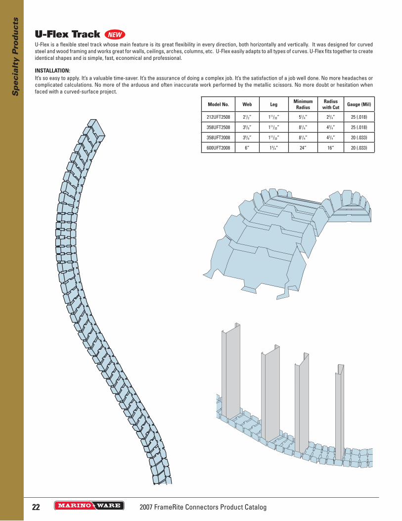
U-Flex is a flexible steel track whose main feature is its great flexibility in every direction, both horizontally and vertically. It was designed for curved steel and wood framing and works great for walls, ceilings, arches, columns, etc. U-Flex easily adapts to all types of curves. U-Flex fits together to create identical shapes and is simple, fast, economical and professional.
INSTALLATION:It’s so easy to apply. It’s a valuable time-saver. It’s the assurance of doing a complex job. It’s the satisfaction of a job well done. No more headaches or complicated calculations. No more of the arduous and often inaccurate work performed by the metallic scissors. No more doubt or hesitation when faced with a curved-surface project.
U-Flex Track
Model No. Web Leg MinimumRadius
Radiuswith Cut Gauge (Mil)
212UFT2508 21/2” 111/32” 51/4” 23/4” 25 (.018)
358UFT2508 35/8” 111/32” 81/4” 43/4” 25 (.018)
358UFT2008 35/8” 111/32” 81/4” 43/4” 20 (.033)
600UFT2008 6” 13/4” 24” 16” 20 (.033)
NEW
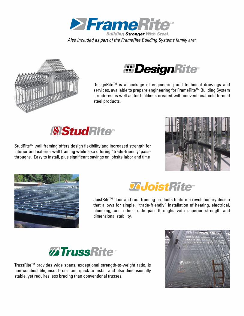
JoistRiteTM floor and roof framing products feature a revolutionary design that allows for simple, “trade-friendly” installation of heating, electrical, plumbing, and other trade pass-throughs with superior strength and dimensional stability.
StudRiteTM wall framing offers design flexibility and increased strength for interior and exterior wall framing while also offering “trade-friendly”pass-throughs. Easy to install, plus significant savings on jobsite labor and time
TrussRiteTM provides wide spans, exceptional strength-to-weight ratio, is non-combustible, insect-resistant, quick to install and also dimensionally stable, yet requires less bracing than conventional trusses.
DesignRiteTM is a package of engineering and technical drawings and services, available to prepare engineering for FrameRiteTM Building System structures as well as for buildings created with conventional cold formed steel products.
Also included as part of the FrameRite Building Systems family are:
Top Related