ZXSDRR8978 - FCC ID Search · PDF fileZXSDRR8978 ... Two 10 Gbps CPRI optical interfaces are...
66
ZXSDR R8978 TDD 8 Path Remote Radio Unit User Manual Version: V5.10 ZTE CORPORATION No. 55, Hi-tech Road South, ShenZhen, P.R.China Postcode: 518057 Tel: +86-755-26771900 Fax: +86-755-26770801 URL: http://support.zte.com.cn E-mail: [email protected]
Transcript of ZXSDRR8978 - FCC ID Search · PDF fileZXSDRR8978 ... Two 10 Gbps CPRI optical interfaces are...

ZXSDR R8978TDD 8 Path Remote Radio Unit
User Manual
Version: V5.10
ZTE CORPORATIONNo. 55, Hi-tech Road South, ShenZhen, P.R.ChinaPostcode: 518057Tel: +86-755-26771900Fax: +86-755-26770801URL: http://support.zte.com.cnE-mail: [email protected]

LEGAL INFORMATIONCopyright © 2014 ZTE CORPORATION.
The contents of this document are protected by copyright laws and international treaties. Any reproduction or
distribution of this document or any portion of this document, in any form by any means, without the prior written
consent of ZTE CORPORATION is prohibited. Additionally, the contents of this document are protected by
contractual confidentiality obligations.
All company, brand and product names are trade or service marks, or registered trade or service marks, of ZTE
CORPORATION or of their respective owners.
This document is provided “as is”, and all express, implied, or statutory warranties, representations or conditions
are disclaimed, including without limitation any implied warranty of merchantability, fitness for a particular purpose,
title or non-infringement. ZTE CORPORATION and its licensors shall not be liable for damages resulting from the
use of or reliance on the information contained herein.
ZTE CORPORATION or its licensors may have current or pending intellectual property rights or applications
covering the subject matter of this document. Except as expressly provided in any written license between ZTE
CORPORATION and its licensee, the user of this document shall not acquire any license to the subject matter
herein.
ZTE CORPORATION reserves the right to upgrade or make technical change to this product without further notice.
Users may visit the ZTE technical support website http://support.zte.com.cn to inquire for related information.
The ultimate right to interpret this product resides in ZTE CORPORATION.
Revision History
Revision Version Revision Date Revision Reason
R1.1 2014-10-30 Added S2600M
R1.0 2014-08-06 First edition
Serial Number: SJ-20140808143736-001
Publishing Date: 2014-10-30 (R1.1)
SJ-20140808143736-001|2014-10-30 (R1.1) ZTE Proprietary and Confidential
ContentsAbout This Manual ......................................................................................... I
Chapter 1 FCC Related Statements .......................................................... 1-1
Chapter 2 Product Overview ..................................................................... 2-12.1 Product Positioning ............................................................................................ 2-1
2.2 Product Features................................................................................................ 2-2
2.3 External View..................................................................................................... 2-2
2.4 Product Specifications ........................................................................................ 2-3
2.4.1 ZXSDR R8978 S2300............................................................................... 2-3
2.4.2 ZXSDR R8978 S2600............................................................................... 2-4
2.4.3 ZXSDR R8978 S2600M............................................................................ 2-4
2.5 External Interfaces ............................................................................................. 2-5
2.6 Installation Modes .............................................................................................. 2-6
2.7 Typical Networking Applications .......................................................................... 2-6
Chapter 3 Product Composition ............................................................... 3-13.1 System Structure................................................................................................ 3-1
3.2 Composition....................................................................................................... 3-2
3.3 LED Indicators ................................................................................................... 3-3
3.4 Physical Interfaces and Cables ........................................................................... 3-5
3.4.1 Protective Grounding Cable ...................................................................... 3-5
3.4.2 DC Power Input Cable .............................................................................. 3-6
3.4.3 LMT/TST Interface Cable.......................................................................... 3-9
3.4.4 Optical Fiber .......................................................................................... 3-10
3.4.5 Antenna Feeder Interface Cable...............................................................3-11
3.4.6 CAL/AISG Interface Cable ...................................................................... 3-13
3.4.7 EAM/RGPS Interface Cable .................................................................... 3-14
3.5 External Cable Connection ............................................................................... 3-14
3.6 Software Composition....................................................................................... 3-15
Chapter 4 Operation and Maintenance..................................................... 4-14.1 Technical Support............................................................................................... 4-1
4.2 Fault Location .................................................................................................... 4-2
4.3 Equipment Maintenance ..................................................................................... 4-3
4.4 Power On .......................................................................................................... 4-4
4.5 Power Off .......................................................................................................... 4-5
I
SJ-20140808143736-001|2014-10-30 (R1.1) ZTE Proprietary and Confidential

4.6 Parts Replacement............................................................................................. 4-6
4.6.1 Replacing the ZXSDR R8978.................................................................... 4-6
4.6.2 Replacing the Optical Module.................................................................... 4-7
4.6.3 Replacing the RF Cable............................................................................ 4-8
Chapter 5 Accessory Devices ................................................................... 5-15.1 Junction Box ...................................................................................................... 5-1
5.2 AC Power Lightening Protection Box ................................................................... 5-3
5.3 Replacing the AC Power Lighting Protection Box.................................................. 5-6
Chapter 6 Technical Specifications .......................................................... 6-16.1 Physical Specifications ....................................................................................... 6-1
6.2 Performance Indexes ......................................................................................... 6-1
6.3 Power Consumption ........................................................................................... 6-2
6.4 Reliability Indexes .............................................................................................. 6-2
6.5 Grounding Requirement...................................................................................... 6-3
6.6 Lightening and Surge Protection ......................................................................... 6-3
Chapter 7 Environment Requirements ..................................................... 7-17.1 Power Supply Requirements ............................................................................... 7-1
7.2 Operating Environment....................................................................................... 7-1
7.3 Storage Environment.......................................................................................... 7-2
Figures............................................................................................................. I
Tables ............................................................................................................ III
Glossary .........................................................................................................V
II
SJ-20140808143736-001|2014-10-30 (R1.1) ZTE Proprietary and Confidential

About This ManualPurposeThis manual describes the software and hardware structures, interfaces and cables,functions, features, technical specifications, installation modes, networking, andmaintenance methods of the ZXSDR R8978.
Intended AudienceThis manual is intended for:
l Base station installation engineersl Base station commissioning engineersl Base station maintenance engineers
What Is in This ManualThis manual contains the following chapters.
Chapter 1, FCC Related
Statements
Describes the statements related to FCC rule.
Chapter 2, Product Overview Describes the external view, interfaces, functions, features, and
typical network applications of the ZXSDR R8978.
Chapter 3, Product Composition Describes the system structure, hardware composition, and
software composition of the ZXSDR R8978.
Chapter 4, Operation and
Maintenance
Provides the technical support contact information, power-on and
power-off flow, and component replacement methods.
Chapter 5, Accessory Devices Describes the accessory devices, including junction box, and AC
power lightening protection box, and the replacement methods.
Chapter 6, Technical
Specifications
Provides the technical specifications of the ZXSDR R8978.
Chapter 7, Environment
Requirements
Describes the environment requirements of the ZXSDR R8978.
ConventionsThis manual uses the following conventions.
Danger: indicates an imminently hazardous situation. Failure to comply can result in
death or serious injury, equipment damage, or site breakdown.
Warning: indicates a potentially hazardous situation. Failure to comply can result in
serious injury, equipment damage, or interruption of major services.
I
SJ-20140808143736-001|2014-10-30 (R1.1) ZTE Proprietary and Confidential

Caution: indicates a potentially hazardous situation. Failure to comply can result in
moderate injury, equipment damage, or interruption of minor services.
Note: provides additional information about a topic.
II
SJ-20140808143736-001|2014-10-30 (R1.1) ZTE Proprietary and Confidential

Chapter 1FCC Related Statements
Warning!
Changes or modifications to this unit not expressly approved by the party responsible forcompliance could void the user’s authority to operate the equipment.
This equipment has been tested and found to comply with the limits for a Class A digitaldevice, pursuant to Part 15 of the FCC Rules. These limits are designed to providereasonable protection against harmful interference when the equipment is operated ina commercial environment. This equipment generates, uses, and can radiate radiofrequency energy and, if not installed and used in accordance with the instruction manual,may cause harmful interference to radio communications. Operation of this equipmentin a residential area is likely to cause harmful interference in which case the user will berequired to correct the interference at his own expense.
Operation of this equipment in a residential area is likely to cause harmful interference inwhich case the user will be required to correct the interference at his own expense.
This equipment complies with FCC radiation exposure limits set forth for an uncontrolledenvironment. This equipment should be installed and operated with minimum distance10.2 m between the radiator & your body.
1-1
SJ-20140808143736-001|2014-10-30 (R1.1) ZTE Proprietary and Confidential

ZXSDR R8978 User Manual
This page intentionally left blank.
1-2
SJ-20140808143736-001|2014-10-30 (R1.1) ZTE Proprietary and Confidential

Chapter 2Product OverviewTable of Contents
Product Positioning ....................................................................................................2-1Product Features........................................................................................................2-2External View .............................................................................................................2-2Product Specifications................................................................................................2-3External Interfaces .....................................................................................................2-5Installation Modes ......................................................................................................2-6Typical Networking Applications .................................................................................2-6
2.1 Product PositioningThe ZXSDR R8978 is an eight-path TD-LTE RRU with high power. It operates with a BBUto cover new outdoor sites.
The ZXSDR R8978 works with a BBU to compose a complete eNodeB and implement thefunctions such as radio transmission in the coverage area and radio channel control.
Figure 2-1 illustrates the position of the ZXSDR R8978 in a LTE network.
Figure 2-1 Position of the RRU in a Network
2-1
SJ-20140808143736-001|2014-10-30 (R1.1) ZTE Proprietary and Confidential

ZXSDR R8978 User Manual
2.2 Product FeaturesUnified PlatformThe ZXSDR R8978 is developed based on the unified SDR platform, which supportssmooth evolution to new technologies in the future, and protects the operators' investmentin maximum.
Energy conservation and environmental protectionl Designed with high-efficiency power amplifier technologies: Crest Factor Reduction
(CFR), Digital Pre-Distortion (DPD) and Doherty to reduce equipment's powerconsumption.
l Uses passive heat dissipation without electrical noise, which can save 35% powerconsumption compared with the traditional air conditioner to effectively reduce theoperators' power consumption cost.
l Supports the energy-saving technologies such as slot-based power saving andvoltage regulation power saving.
Multi-Carrier, MIMO, BF, and High Performancel Supports multiple frequency bands such as 2.3 GHz/2.6 GHz to satisfy the
requirements of various operators.l Supports flexible configuration of up to TD-LTE 4x20 MHz multi-carriers to fully and
flexibly utilize the operators' spectrum.
High Output PowerUp to 160 W (8x20 W) output power is provided to satisfy the power requirements for highcapacity and large coverage.
10 Gbps Optical InterfaceTwo 10 Gbps CPRI optical interfaces are provided to satisfy the TD-LTE CPRI flowrequirement. CPRI optical interface multi-mode transmission is supported (the 6 Gbpsoptical interface rate is also supported).
2.3 External ViewFigure 2-2 shows the external view of the ZXSDR R8978.
2-2
SJ-20140808143736-001|2014-10-30 (R1.1) ZTE Proprietary and Confidential

Chapter 2 Product Overview
Figure 2-2 External View
2.4 Product SpecificationsThe ZXSDRR8978 is an eight-channel RRU that an be used for networking TD-LTEmacrocells.
In this manual, all the descriptions for the ZXSDR R8978 are applicable to the followingspecifications unless specially stated:
l ZXSDR R8978 S2300l ZXSDR R8978 S2600l ZXSDR R8978 S2600M
2.4.1 ZXSDR R8978 S2300For the key features of the ZXSDR R8978 S2300, refer to Table 2-1.
Table 2-1 Key Features of the ZXSDR R8978 S2300
Item Description
Radio access mode TD-LTE
Frequency band 2300 MHz~2400 MHz
Antenna Supports 4×4 MIMO dual TRX channels.
Maximum number of carriers TD-LTE: 4×20 MHz
2-3
SJ-20140808143736-001|2014-10-30 (R1.1) ZTE Proprietary and Confidential

ZXSDR R8978 User Manual
Item Description
Signal bandwidth 80 MHz
Maximum power output in each channel 20 W
Power input DC: -48 V DC
AC: 100 V AC/110 V AC/220 V AC
2.4.2 ZXSDR R8978 S2600For the key features of the ZXSDR R8978 S2600, refer to Table 2-2.
Table 2-2 Key Features of the ZXSDR R8978 S2600
Item Description
Radio access mode TD-LTE
Frequency band 2575 MHz–2635MHz
Antenna Supports 4×4 MIMO dual TRX channels.
Maximum number of carriers TD-LTE: 3×20 MHz
Signal bandwidth 60 MHz
Maximum power output in each channel 25 W
Power input DC: -48 V DC
AC: 100 V AC/110 V AC/220 V AC
2.4.3 ZXSDR R8978 S2600MFor the key features of the ZXSDR R8978 S2600M, refer to Table 2-3.
Table 2-3 Key Features of the ZXSDR R8978 S2600M
Item Description
Radio access mode TD-LTE
Frequency band 2496 MHz~2596 MHz
Antenna Smart Antenna
RET
8–path transceiving channels
Maximum number of carriers TD-LTE: 4x20 MHz 2x20 MHz
Signal bandwidth 100 MHz
Maximum power output in each channel 20 W
Power input -48 VDC
2-4
SJ-20140808143736-001|2014-10-30 (R1.1) ZTE Proprietary and Confidential

Chapter 2 Product Overview
2.5 External InterfacesFigure 2-3 illustrates the external interfaces of the ZXSDR R8978.
Figure 2-3 External Interfaces
For a description of the external interfaces, refer to Table 2-4.
Table 2-4 External Interface Description
External Device Description External Interface
BBU BBU performs the functions such as GPS
synchronization, main control, and baseband
processing.
Logical interface: Ir interface
Physical interface: optical
fiber interface
UE UE accomplishes the Uu interface functions of
transmitting voice and data services.
Logical interface: Uu interface
Physical interface: none
User device External environment monitoring device Logical interface: not
standardized
Physical interface: dry contact
2-5
SJ-20140808143736-001|2014-10-30 (R1.1) ZTE Proprietary and Confidential

ZXSDR R8978 User Manual
External Device Description External Interface
RRU LMT Operates and maintains the RRU at the local
end
Logical interface: not
standardized
Physical interface: Ethernet
interface
Cascade RRU Upstream RRU Logical interface: Ir interface
Physical interface: optical
fiber interface
• External interfaces exclude the power and antenna interface of the RRU.
Note:
The LMT at the BBU side can operate and maintain multiple RRUs under the BBU. ZTENetNumen™ EMS provides unified operation and maintenance on multiple sites.
2.6 Installation ModesThe ZXSDR R8978 supports three installation modes:
l A single RRU mounted on a polel Two RRUs mounted on a polel Mounted on a walll Mounted on slot steell Mounted on angle steel
2.7 Typical Networking ApplicationsThe ZXSDR R8978 supports the following networking solutions:l Chain networking
Chain networking applies to strip-shaped areas with sparse population, where opticalfibers can be laid conveniently. Figure 2-4 shows a chain networking solution.
Figure 2-4 Chain Networking
l Star networking
In a star networking solution, a BBU is connected to each RRU and the RRU isthe terminal equipment. This networking type is simple and easy for maintenance
2-6
SJ-20140808143736-001|2014-10-30 (R1.1) ZTE Proprietary and Confidential

Chapter 2 Product Overview
and engineering. Because the signal passes through fewer intermediate links alongthe transmission path, the link reliability is much higher. Figure 2-5 shows a starnetworking solution.
Figure 2-5 Star Networking
2-7
SJ-20140808143736-001|2014-10-30 (R1.1) ZTE Proprietary and Confidential

ZXSDR R8978 User Manual
This page intentionally left blank.
2-8
SJ-20140808143736-001|2014-10-30 (R1.1) ZTE Proprietary and Confidential

Chapter 3Product CompositionTable of Contents
System Structure........................................................................................................3-1Composition ...............................................................................................................3-2LED Indicators............................................................................................................3-3Physical Interfaces and Cables ..................................................................................3-5External Cable Connection.......................................................................................3-14Software Composition ..............................................................................................3-15
3.1 System StructureFigure 3-1 shows the system structure of the ZXSDR R8978.
Figure 3-1 System Structure
Table 3-1 describes the subsystems of the ZXSDR R8978.
Table 3-1 Subsystem Description
Name Type Function
RRU software
subsystem
Software
subsystem
Provides the system operating system and OM functions
Transceiver Hardware
subsystem
l Power interface
l Optical interface
l Control functions
l Clock functions
l DIF
l TRX
8T8R filter unit Hardware
subsystem
Eight-channel filter
Structure subsystem Structure
subsystem
Provides equipment protection, heat dissipation, and
installation, and module structure, heat dissipation, and
installation.
3-1
SJ-20140808143736-001|2014-10-30 (R1.1) ZTE Proprietary and Confidential

ZXSDR R8978 User Manual
3.2 CompositionFigure 3-2 shows the composition of the ZXSDR R8978.
Figure 3-2 Product Composition
1. Radiating pin2. Handle3. LED indicators
4. Operation andmaintenancecavity
5. Antenna interface6. CAL/AISG interface
7. Grounding bolt8. Breathable valve9. EAM/RGPS interface
l The operation and maintenance cavity contains one DC power interface, two opticalinterfaces (OPT1 and OPT2), one RRU LMT/test interface (LAM/TST).
l The equipment has six LED indicators.l A handle is installed on the upper shell to facilitate installation and transportation.l At the bottom of the equipment, there are eight antenna interfaces (ANT1–ANT8), one
hermetic seal (breathable valve), one antenna calibration interface (CAL/AISG), andone dry contract user device interface (EAM/RGPS).
3-2
SJ-20140808143736-001|2014-10-30 (R1.1) ZTE Proprietary and Confidential

Chapter 3 Product Composition
Note:
The LMT/TST interface is used for ZTE maintenance personnel to perform commissioningand maintenance.
3.3 LED IndicatorsAn indicator indicates the operating status of a device. Figure 3-3 shows the positions ofthe indicators.
Figure 3-3 LED Indicators
Table 3-2 describes the LED indicators.
3-3
SJ-20140808143736-001|2014-10-30 (R1.1) ZTE Proprietary and Confidential

ZXSDR R8978 User Manual
Table 3-2 Indicator Descriptions
Name Indication Color Description
OFF: The system is not powered.
ON: The system is powered. The software system is not
running.
Flashing slowly (ON for 1 s and OFF for 1 s): The system is
powered. The software system is being started.
Flashing normally (ON for 0.3 s and OFF for 0.3 s): The
system is powered. The software system has been started.
The communication between the RRU and BBU is normal.
RUN Operation
indicator
Green
Flashing fast (ON for 70 ms and OFF for 70 ms): The system
is powered. The software system has been started. The link
between the ZXSDR R8978 and BBU is not established.
OFF: There is no alarm.ALM Alarm indicator Red
ON: There is an alarm.
OFF: The optical interface does not receive optical signals.
ON: The optical interface has received optical signals and
the link is not synchronized.
OPT1 Indicator of
optical interface
1
Green
Flashing (ON for 0.3 s and OFF for 0.3 s): The optical interface
has received optical signals and the link is synchronized.
OFF: The optical interface does not receive optical signals.
ON: The optical interface has received optical signals and
the link is not synchronized.
OPT2 Indicator of
optical interface
2
Green
Flashing (ON for 0.3 s and OFF for 0.3 s): The optical interface
has received optical signals and the link is synchronized.
OFF: VSWRs at all antenna interfaces of the transmitting
links are normal.
VSWR Indicator of
the VSWR at
the antenna
interface
Red
ON: There is a VSWR alarm at the antenna interface of the
transmitting link.
Solid ON: Indicates that the radio links are successfully
established, and cells are established.
ACT Radio link
status indicator
Green
OFF: Indicates that no radio links are established or
establishment failed, and no cell exists.
• The ALM indicator does not indicate alarms of the optical interfaces (OPT1 and OPT2) and VSWRalarms at the antenna interfaces.
3-4
SJ-20140808143736-001|2014-10-30 (R1.1) ZTE Proprietary and Confidential
Chapter 3 Product Composition
3.4 Physical Interfaces and Cables
3.4.1 Protective Grounding Cable
FunctionThe protective grounding point is located at the bottom of the handle.
The protective grounding cable provides protective ground for the system. There are a totalof two bolts that provide a grounding connection to the ZXSDR R8978. The grounding boltcan be connected with a dual hole OT terminal that complies with theGR1089 specification.The OT terminal can be connected to the 16 mm2 multi-cores yellow-green copper wire.
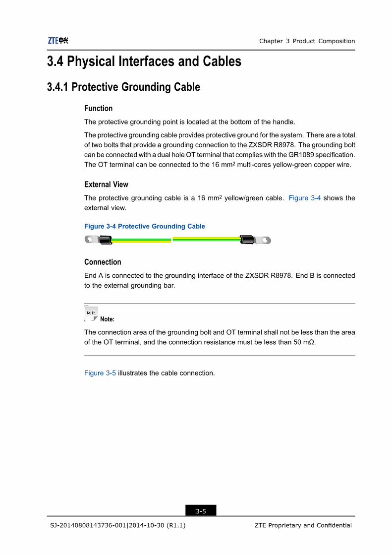
External ViewThe protective grounding cable is a 16 mm2 yellow/green cable. Figure 3-4 shows theexternal view.
Figure 3-4 Protective Grounding Cable
ConnectionEnd A is connected to the grounding interface of the ZXSDR R8978. End B is connectedto the external grounding bar.
Note:
The connection area of the grounding bolt and OT terminal shall not be less than the areaof the OT terminal, and the connection resistance must be less than 50 mΩ.
Figure 3-5 illustrates the cable connection.
3-5
SJ-20140808143736-001|2014-10-30 (R1.1) ZTE Proprietary and Confidential

ZXSDR R8978 User Manual
Figure 3-5 Connection of the Protective Grounding Cable
Note:
The two bolts on the left are used for installing the protective grounding cable. The bolt onthe right is only used for fixing and does not connect to any cable.
3.4.2 DC Power Input Cable
FunctionThe DC power input interface is located in the operation and maintenance cavity of theZXSDR R8978.
The DC power input cable leads the external DC power into the operation andmaintenancecavity of the ZXSDR R8978. It connects to the DC power through a dual-core DC bracketand a dual-core DC connector, to provide -48 V DC power input for the RRU.
3-6
SJ-20140808143736-001|2014-10-30 (R1.1) ZTE Proprietary and Confidential

Chapter 3 Product Composition
Caution!
The 10 mm2 DC power cable cannot be directly connected to the ZXSDR R8978, andneeds to be converted to a 4mm2DCpower cable through a junction box before connectingto the ZXSDR R8978.
The ZXSDR R8978 does not have an AC power interface. The AC power should beconverted into DC power through the outdoor AC power lightening protection box andthen connected to the ZXSDR R8978.
External ViewThe DC power cable is a blue-black cable. Figure 3-6 shows the external view.
Figure 3-6 DC Power Input Cable
1. Copper wire2. Shielding layer
3. -48 V core4. -48 V GND core
Signal Description
Signal Name Signal Meaning Wire Color
-48 V -48 V power Blue
-48 V GND -48 V ground Black
Connection
If... Then...
The junction box is not required if the indoor power lightening protection
box is near to the ZXSDR R8978 and voltage drop can be ignored.
The indoor DC power distribution unit (with a power switch) connects to
the lighting protection box of the indoor DC power supply.
Use the DC power supply
without a junction box
Connect the ZXSDR R8978 to the indoor DC power lighting protection
box (there are a total of three outputs in the indoor DC power lighting
protection box, each of which has an air switch and can be connected
to an RRU).
3-7
SJ-20140808143736-001|2014-10-30 (R1.1) ZTE Proprietary and Confidential

ZXSDR R8978 User Manual
If... Then...
If voltage drop occurs due to the distance between the ZXSDR R8978
and the indoor DC power lighting protection box, a power cable with a
larger diameter size is needed to reduce the voltage drop caused by long
distance transmission. A junction box is needed to convert the cables to
a different size.
The indoor DC power distribution unit (with a power switch) connects to
the lighting protection box of the indoor DC power supply.
Connect the junction box to the indoor DC power lighting protection
box (there are a total of three outputs in the indoor DC power lighting
protection box, each of which has an air switch and can be connected
to an RRU).
Use the DC power supply
with a junction box
After the DC power cable is converted by the junction box, it can be
connected to the ZXSDR R8978.
The junction box is not required because the AC power supply is low with
a large voltage and voltage drop can be ignored.
Connect the indoor AC power distribution cabinet to the outdoor AC
power lightening protection box (there are a total of three outputs in the
indoor AC power distribution cabinet, each of which has a power switch
and can be connected to an RRU).
Use the AC power supply
without a junction box
Connect the outdoor AC power lightening protection box to the ZXSDR
R8978.
Figure 3-7 illustrates the cable connection.
3-8
SJ-20140808143736-001|2014-10-30 (R1.1) ZTE Proprietary and Confidential

Chapter 3 Product Composition
Figure 3-7 Connection of DC Power Input Cable
Note:l The two cores of the DC power cable End A should be wrapped with a tube terminal.
After the tube terminal is crimped and inserted to the dual core DC connector, the DCpower cable can be inserted to the dual core DC socket through the DC connector.
l The End B of the DC power cable is bare and connects to the external power supply.l The two ends of the power cable must be made at the site.
3.4.3 LMT/TST Interface Cable
FunctionThe LMT/TST interface is located in the operation andmaintenance cavity. It uses an RJ45socket.
The LMT interface is used for the interaction between the LMT and ZXSDR R8978 throughan Ethernet port using TCP/IP. TELNET command lines are supported.
ConnectionEnd A is connected to the LMT interface in the operation and maintenance cavity. End Bis connected to the LMT or PC.
Figure 3-8 illustrates the cable connection.
3-9
SJ-20140808143736-001|2014-10-30 (R1.1) ZTE Proprietary and Confidential
ZXSDR R8978 User Manual
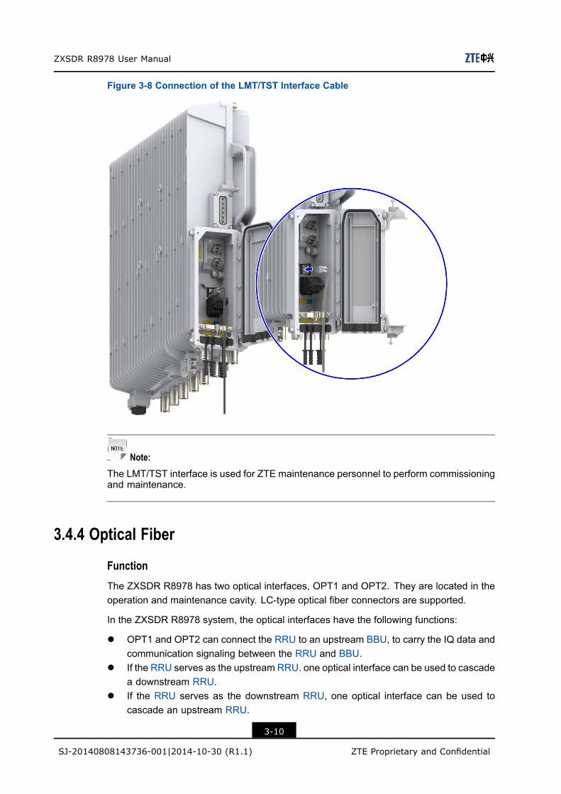
Figure 3-8 Connection of the LMT/TST Interface Cable
Note:The LMT/TST interface is used for ZTE maintenance personnel to perform commissioningand maintenance.
3.4.4 Optical Fiber
FunctionThe ZXSDR R8978 has two optical interfaces, OPT1 and OPT2. They are located in theoperation and maintenance cavity. LC-type optical fiber connectors are supported.
In the ZXSDR R8978 system, the optical interfaces have the following functions:
l OPT1 and OPT2 can connect the RRU to an upstream BBU, to carry the IQ data andcommunication signaling between the RRU and BBU.
l If the RRU serves as the upstream RRU. one optical interface can be used to cascadea downstream RRU.
l If the RRU serves as the downstream RRU, one optical interface can be used tocascade an upstream RRU.
3-10
SJ-20140808143736-001|2014-10-30 (R1.1) ZTE Proprietary and Confidential

Chapter 3 Product Composition
External ViewThe optical fiber uses LC-type connectors. Figure 3-9 shows the external view.
Figure 3-9 Optical Fiber
ConnectionEnd A is connected to the optical ports (OPT1 and OPT2) of the ZXSDR R8978. End B isconnected to the BBU/dowstream RRU/upstream RRU.
Figure 3-10 illustrates the cable connection.
Figure 3-10 Connection of the Optical Fiber
3.4.5 Antenna Feeder Interface Cable
FunctionThe antenna feeder interface is located on the external filter at the equipment bottom. Ituses N-type female connectors.
The antenna feeder interface cable connects the antenna interface of the ZXSDR R8978to the antenna. It is used for the signal receiving and transmission at the antenna.
3-11
SJ-20140808143736-001|2014-10-30 (R1.1) ZTE Proprietary and Confidential

ZXSDR R8978 User Manual
External ViewThe antenna feeder interface cable is a 50 Ω cable with a diameter of 1/2 in (1 in=25.4mm). Both ends are N-type male connectors. Figure 3-11 shows the external view.
Figure 3-11 Antenna Feeder Interface Cable
ConnectionEnd A is connected to the ANT interface of the ZXSDR R8978. End B is connected to thecorresponding interface of the main antenna feeder.
The antenna feeder interface cable is a 1/2 inch jumper. Figure 3-12 illustrates the cableconnection.
Figure 3-12 Connection of the Antenna Feeder Interface Cable
3-12
SJ-20140808143736-001|2014-10-30 (R1.1) ZTE Proprietary and Confidential

Chapter 3 Product Composition
3.4.6 CAL/AISG Interface Cable
FunctionThe CAL interface is located at the external filter at the bottom of the ZXSDR R8978. Ituses a type-N female connector.
The CAL interface cable used by the ZXSDR R8978 uses a jumper with a diameter of 1/2inch. Both ends are N-type male connectors. The CAL interface supports antenna channelcalibration and AISG for RET antennas.
The CAL interface integrates AISG and antenna calibration. If an RET antenna is used, theCAL interface of the ZXSDR R8978 is connected to the integrated interface of the antenna.
External ViewThe CAL interface cable is an RF cable with a diameter of 1/2 in (1 in=25.4 mm). Bothends are N-type male connectors. Figure 3-13 shows the external view.
Figure 3-13 CAL Interface Cable
ConnectionEnd A is connected to the CAL interface of the ZXSDR R8978. End B is connected to theCAL interface of the antenna.
Figure 3-14 illustrates the cable connection.
3-13
SJ-20140808143736-001|2014-10-30 (R1.1) ZTE Proprietary and Confidential

ZXSDR R8978 User Manual
Figure 3-14 Connection of the CAL Interface Cable
3.4.7 EAM/RGPS Interface Cable
FunctionThe dry contact (EAM) interface is located at the external filter at the bottom of the ZXSDRR8978. It uses an eight-core round connector. It supports the RGPS functions and onedry contract input to transparently transmit the external device status.
The RGPS receiver is located at the GPS receiving antenna. Installed near the antenna,the satellite card transmits the output digital signal to the clock main control card througha differential line. Because digital signal transmission is not affected by RF signalattenuation, the remote distance is long and good reliability and maintainability is ensured.
ConnectionEnd A is connected to the EAM interface of the ZXSDR R8978. End B is connected to thedry contact output/RGPS interface of the external device.
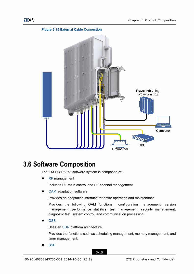
3.5 External Cable ConnectionFigure 3-15 illustrates the external cable connection.
3-14
SJ-20140808143736-001|2014-10-30 (R1.1) ZTE Proprietary and Confidential
Chapter 3 Product Composition
Figure 3-15 External Cable Connection
3.6 Software CompositionThe ZXSDR R8978 software system is composed of:
l RF management
Includes RF main control and RF channel management.
l OAM adaptation software
Provides an adaptation interface for entire operation and maintenance.
Provides the following OAM functions: configuration management, versionmanagement, performance statistics, test management, security management,diagnostic test, system control, and communication processing.
l OSS
Uses an SDR platform architecture.
Provides the functions such as scheduling management, memory management, andtimer management.
l BSP
3-15
SJ-20140808143736-001|2014-10-30 (R1.1) ZTE Proprietary and Confidential

ZXSDR R8978 User Manual
Uses a unified architecture design and provides a unified interface for the upper layer.
l OS
Uses the Linux system independently developed by ZTE.
Figure 3-16 shows the software composition of the ZXSDR R8978.
Figure 3-16 Software Composition
3-16
SJ-20140808143736-001|2014-10-30 (R1.1) ZTE Proprietary and Confidential

Chapter 4Operation and MaintenanceTable of ContentsTechnical Support.......................................................................................................4-1Fault Location.............................................................................................................4-2Equipment Maintenance.............................................................................................4-3Power On...................................................................................................................4-4Power Off ...................................................................................................................4-5Parts Replacement.....................................................................................................4-6
4.1 Technical SupportZTE technical support contract information is pasted in a conspicuous position in theequipment room, see Figure 4-1.
4-1
SJ-20140808143736-001|2014-10-30 (R1.1) ZTE Proprietary and Confidential

ZXSDR R8978 User Manual
Figure 4-1 ZTE Technical Support Contact Information
4.2 Fault LocationFor the fault location methods in routine maintenance, refer to Table 4-1.
Table 4-1 Fault Location Methods
Maintenance Method Description
Checking Alarms and
Operation Logs
This is the most common method for troubleshooting. By checking the
alarm management tab of the operation and maintenance system, you
can check the alarms and operation logs.
l Check and analysis of the current, historical alarms and common
notifications through the alarm management tab, to find the abnormal
status, locating and handling faults.
4-2
SJ-20140808143736-001|2014-10-30 (R1.1) ZTE Proprietary and Confidential
Chapter 4 Operation and Maintenance
Maintenance Method Description
l By checking the operation logs in user management, you can
trace system parameter modification, locate relevant terminals and
operators, and discover the faults caused by manual operations.
Performance Analysis By checking the performance management tab, you can create different
performance test tasks, generate the relevant performance reports to
determine the system performance indexes. By analyzing this information,
you can find the load distribution in the network and adjust the relevant
network parameters, to improve the integrated network performance in
time.
Instrument and Meter
Analysis
Auxiliary instruments, such as test UE, signaling analyzers, and bit
error analyzers, can be used for fault analysis, fault location and
troubleshooting.
Replacement You can replace a faulty part with a spare part or a peer part that operates
properly in the system to locate a fault. For fault location by using
the replacement method, you need to perform relevant operations in
accordance with the replacement procedures described in this manual.
Self-test The system performs a self-test when it is powered on again. During the
self-test, the indicators flash in accordance with relevant rules. You can
locate faults by checking the indicators.
Integrated Method In actual operation, all the methods can be used for troubleshooting. You
can handle different faults based on the fault location methods and past
experience.
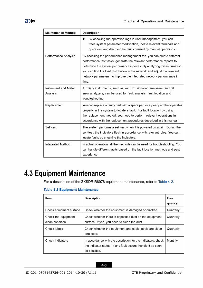
4.3 Equipment MaintenanceFor a description of the ZXSDR R8978 equipment maintenance, refer to Table 4-2.
Table 4-2 Equipment Maintenance
Item Description Fre-quency
Check equipment surface Check whether the equipment is damaged or cracked Quarterly
Check the equipment
clean condition
Check whether there is deposited dust on the equipment
surface. If yes, you need to clean the dust.
Quarterly
Check labels Check whether the equipment and cable labels are clean
and clear.
Quarterly
Check indicators In accordance with the description for the indicators, check
the indicator status. If any fault occurs, handle it as soon
as possible.
Monthly
4-3
SJ-20140808143736-001|2014-10-30 (R1.1) ZTE Proprietary and Confidential

ZXSDR R8978 User Manual
4.4 Power On
Caution!
Before power on, you need to check the equipment and cable installation in detail,to ensure that all the installation results comply with the engineering installationspecifications.
Figure 4-2 shows the power-on flow.
Figure 4-2 Power-on Flow
For a description of the ZXSDR R8978 power-on flow, refer to Table 4-3.
4-4
SJ-20140808143736-001|2014-10-30 (R1.1) ZTE Proprietary and Confidential

Chapter 4 Operation and Maintenance
Table 4-3 Power-on Steps
Item Power-on Steps
DC power
supply
1. Turn on the switch of the power distribution unit, and check whether the equipment
output voltage is in the normal range.
2. Turn on the switch of the indoor DC power lighting protection box of the ZXSDR
R8978. Power the ZXSDR R8978 on, and test whether the RRU input voltage
is in the normal range.
3. Check whether the BBU indicator or the RRU indicator is normal.
AC power
supply
1. Turn on the switch of the AC power distribution unit of the ZXSDR R8978, and
check whether the equipment output voltage is in the normal range.
2. Check whether the BBU indicator or the RRU indicator is normal.
Note:
To avoid current surge, you need to power on the RRUs in the cell sequence every 30s. At the same time, you can check whether the cables of a cell are connected properlythrough the BBU indicator.
4.5 Power OffPower-off of the ZXSDR R8978 includes:
l Emergency power-off: occurs when the equipment room is on fire, flooding or in smog.l Common power-off: occurs in some application scenarios, for example, equipment
move or expected local power outage.
For a description of the ZXSDR R8978 power-off flow, refer to Table 4-4.
Table 4-4 Power-off Steps
Item Emergency Power-off Common Power-off
DC power supply Turn off the air switch
of the indoor DC power
distribution unit.
1. Turn off the air switch of the DC power
lighting protection box of the ZXSDR
R8978.
2. Turn off the air switch of the indoor DC
power distribution unit.
AC power supply Turn off the air switch of the indoor AC power distribution unit.
4-5
SJ-20140808143736-001|2014-10-30 (R1.1) ZTE Proprietary and Confidential

ZXSDR R8978 User Manual
4.6 Parts Replacement
4.6.1 Replacing the ZXSDR R8978Locate the ZXSDR R8978 faults through observation and analysis, and determine whetherto replace the ZXSDR R8978. Replacing the ZXSDR R8978 will interrupt all the servicescarried by the ZXSDR R8978.
Prerequisitel Verify the hardware type of the faulty ZXSDR R8978. Prepare a proper ZXSDR
R8978. The specifications of the proper ZXSDR R8978 must be consistent with thefaulty one.
l Prepare the following tools.
Tool Function
Wrench Installs or uninstalls the RF cables
M5 cross screw driver Installs or uninstalls the ZXSDR R8978 maintenance cavity, or
fastens the screws and protection grounding cables.
Waterproof tape Provides waterproof protection for the RF cable connectors
Sticker Marks the connection of the cables to be replaced (after the
replacement, all the cables must be reconnected to the place
where they were)
Moisture proof antistatic
bag and carton
Stores the faulty ZXSDR R8978
Steps1. Power off the ZXSDR R8978.
2. Open the cover of the ZXSDRR8978maintenance cavity by using theM5 screw driver.
3. Paste a label at each end of every optical fiber.
4. Remove the fix screws from the cable crimper by using the M5 screwdriver.
5. Pull up the insulating part of the dual core DC connector against the direction of thearrow marked on the shell. Pull out the connector and uninstall the power cables.
6. Press the blue crimper of the fiber, and pull the fiber out of the connector.
7. Use the M5 cross screwdriver to remove the grounding bolt and remove the protectivegrounding cable.
8. Remove all the waterproof tapes from the jumpers of the antenna port. Uninstallthe jumper from the ZXSDR R8978 antenna port by using the wrench with insulationprotective treatment.
9. Uninstall the AISG/EAM cable.
4-6
SJ-20140808143736-001|2014-10-30 (R1.1) ZTE Proprietary and Confidential

Chapter 4 Operation and Maintenance
10. Tighten the jacking screw clockwise and jack the ZXSDRR8978 chassis. Then, loosenthe plate-pressing bolt anti-clockwise.
11. Pull up the ZXSDR R8978 from the pole or wall-mounting bracket, and remove theZXSDR R8978.
12. Put the faulty equipment into the moisture proof antistatic bag. Label the equipmentmodel, sector ID and fault information on the bag. Put the faulty equipment into thecarton and label the same information as the antisatic bag.
13. Reinstall all equipment parts and tighten every screw.
14. Connect all cables with waterproof and insulation protective treatment.
15. Power on the ZXSDR R8978.
16. The ZXSDR R8978 perform the self-test process after it is powered on. During theself-test, you need to observe the indicator status and perform operations accordingly.
If... Then...
The indicator is normal, which means
that services are restored.
The self-test and replacement are successful.
The indicator is abnormal, which means
that services are not restored.
Troubleshoot the fault and handle the relevant alarms, or
contact ZTE technical support.
– End of Steps –
4.6.2 Replacing the Optical ModuleThe optical module provides the optics and electrical conversion. Replacing the opticalmodule will interrupt all the services carried on the optical module.
Caution!l The optical module supports hot plugging. Before hot plugging, you must wear the
antistatic wrist strap.l Do not look directly at the optical module inside when replacing the optical fiber,
avoiding damage to your eyes.
Prerequisitel Prepare a proper optical module.l Take a record of the connection position at both ends of the faulty optical modules and
fibers. Mark the positions between the optical module and fibers.
Tool Function
Antistatic wrist strap Provides antistatic protection
4-7
SJ-20140808143736-001|2014-10-30 (R1.1) ZTE Proprietary and Confidential

ZXSDR R8978 User Manual
Tool Function
M5 cross screw driver Installs or uninstalls the ZXSDR R8978 maintenance cavity
Sticker Marks the connection of the cables to be replaced (after the
replacement, all the cables must be reconnected to the place
where they were)
Moisture-proof antistatic bag
and carton
Stores the faulty optical module
Steps1. Open the cover of the maintenance cavity by using the M5 screw driver.
2. Paste a label at each end of every optical fiber.
3. Press the blue clamp of the fiber, and pull the fiber connector out of the optical moduleto be replaced.
4. Pull the optical module out of the slot.
5. Install the proper optical module into the slot.
6. Remove the dustproof cap, and connect the fiber connector to the new optical module.
7. Check whether the optical module is operating properly in accordance with theindicator status.
8. Tighten the fiber clamp and close the maintenance cavity.
– End of Steps –
4.6.3 Replacing the RF CableThe RF cable transmits or receives RF signals. Locate the faults through observation andanalysis, and ensure that whether to replace the RF cable. Replacing the RF cable willinterrupt all the services carried by the ZXSDR R8978.
Prerequisitel Prepare a proper RF cable to be replaced.
Each site has a set of RF cables corresponding to the site type.
à For BTS expansion or modification, you can select a set of RF cablescorresponding to the site type.
à For replacement of a single RF cable, you can select a proper RF cable from theRF cable set.
Check whether the core connector of the RF cable is proper.
l Prepare the following tools.
4-8
SJ-20140808143736-001|2014-10-30 (R1.1) ZTE Proprietary and Confidential

Chapter 4 Operation and Maintenance
Tool Function
Wrench Installs or uninstalls the RF cable
Waterproof tape Provides waterproof protection for the RF cable connector
Sticker Marks the connection of the cable to be replaced (after the
replacement, the cable must be reconnected to the place where
it was)
Moisture-proof antistatic bag
and carton
Stores the faulty RF cable
Steps1. Power off the ZXSDR R8978.
2. Remove the waterproof tape of the RF cable.
3. Loosen the connectors of the RF cables by using the wrench.
4. Put the faulty cable into themoisture proof antistatic bag. Label the cablemodel, sectorID and fault information on the bag. Put the faulty cable into the carton and label thesame information as the antisatic bag.
5. Connect the proper RF cable in accordance with the previous connection, see Figure4-3.
Figure 4-3 Connecting the RF cable
Caution!
During the uninstallation process, take off the connector carefully. Try not to damagethe connector.
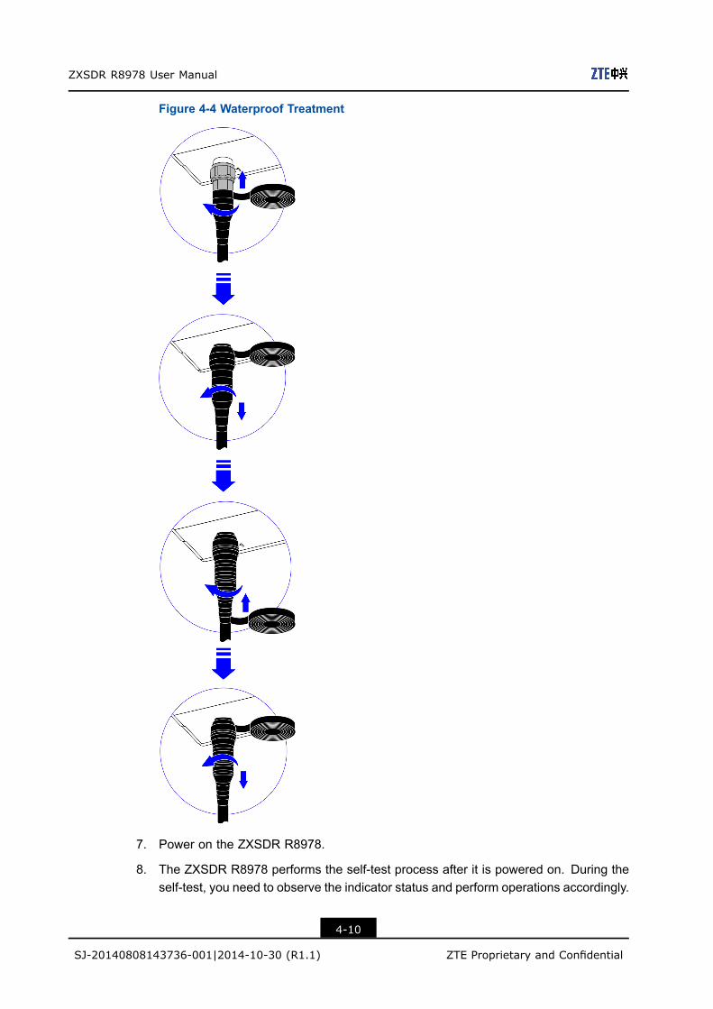
6. Wrap the RF cable connectors with waterproof tape, see Figure 4-4.
4-9
SJ-20140808143736-001|2014-10-30 (R1.1) ZTE Proprietary and Confidential
ZXSDR R8978 User Manual
Figure 4-4 Waterproof Treatment
7. Power on the ZXSDR R8978.
8. The ZXSDR R8978 performs the self-test process after it is powered on. During theself-test, you need to observe the indicator status and perform operations accordingly.
4-10
SJ-20140808143736-001|2014-10-30 (R1.1) ZTE Proprietary and Confidential

Chapter 4 Operation and Maintenance
If... Then...
The indicator is normal, which
means that services are restored.
The self-test and replacement are successful.
The indicator is abnormal, which
means that services are not
restored.
Troubleshoot the fault and handle the relevant alarms, or
contact ZTE technical support.
– End of Steps –
4-11
SJ-20140808143736-001|2014-10-30 (R1.1) ZTE Proprietary and Confidential

ZXSDR R8978 User Manual
This page intentionally left blank.
4-12
SJ-20140808143736-001|2014-10-30 (R1.1) ZTE Proprietary and Confidential

Chapter 5Accessory DevicesTable of Contents
Junction Box ..............................................................................................................5-1AC Power Lightening Protection Box..........................................................................5-3Replacing the AC Power Lighting Protection Box .......................................................5-6
5.1 Junction BoxFunctionWhen the DC power supply is far from the ZXSDR R8978, to avoid voltage drop, a 2×10mm2 DC power cable needs to be used. To connect to the 2×4 mm2 DC power cable usedby the ZXSDR R8978, the 2×10 mm2 DC power cable should be converted through thejunction box.
External ViewFigure 5-1 shows the external view of the junction box.
Figure 5-1 Junction Box
5-1
SJ-20140808143736-001|2014-10-30 (R1.1) ZTE Proprietary and Confidential

ZXSDR R8978 User Manual
SpecificationsTable 5-1 shows the specifications of the junction box.
Table 5-1 Junction Box Specifications
Name Specification
Height × Width × Depth 233 mm × 119 mm × 55 mm (excluding the handle and waterproof cap)
Installation ModeFor single RRU pole-mounted installation or wall-mounted installation, the junction box canbe installed at a side (recommended) or the front of the RRU through an adaptor. For twoRUUl pole-mounted installation, the junction box needs to be installed on the pole.
Figure 5-2 shows how to install the junction box at a side for example.
Figure 5-2 Junction Box Installation
Interfaces and Cable ConnectionFigure 5-3 shows the interfaces and cable connection of the junction box.
5-2
SJ-20140808143736-001|2014-10-30 (R1.1) ZTE Proprietary and Confidential

Chapter 5 Accessory Devices
Figure 5-3 Interfaces and Cable Connection
Interface Name Cable Description
INPUT 2×10 mm2 DC power cable
OUTPUT 2×4 mm2 DC power cable
5.2 AC Power Lightening Protection BoxFunctionThe outdoor AC power lightening protection box is PPC33 A009. It protects the AC currentfrom lightening and coverts AC into the DC that is applicable for the ZXSDR R8978.
External ViewFigure 5-4 shows the external view of the AC power lightening protection box.
5-3
SJ-20140808143736-001|2014-10-30 (R1.1) ZTE Proprietary and Confidential

ZXSDR R8978 User Manual
Figure 5-4 External View
SpecificationsTable 5-2 shows the specifications of the AC power lightening protection box.
Table 5-2 Specifications of the AC Power Lightening Protection Box
Item Specification
Height × Width × Depth 300 mm × 250 mm × 118 mm (excluding the
handle and waterproof cap
Installation mode Pole-mounted installation, all-mounted installation
Lightening protection index 20 kA
Installation ModesThe AC power lightening protection box can be mounted on a pole or wall, see Figure 5-5.
5-4
SJ-20140808143736-001|2014-10-30 (R1.1) ZTE Proprietary and Confidential

Chapter 5 Accessory Devices
Figure 5-5 Installation Modes
Interfaces and Cable ConnectionOpen the AC power lightening protection box and connect the internal and external cables,see Figure 5-6.
Figure 5-6 Interfaces and Cable Connection
Name Description
-220 AC_L 220 V AC live line
-220 AC_N 220 V AV neutral line
5-5
SJ-20140808143736-001|2014-10-30 (R1.1) ZTE Proprietary and Confidential

ZXSDR R8978 User Manual
Name Description
-48 V DC -48 V DC neutral line
-48 V DC RTN -48 V DC earth line
PE Protective grounding cable
5.3 Replacing the AC Power Lighting Protection BoxIf the AC power lighting protection box has an abnormal output but the input is normal, ithas some faults and should be replaced immediately.
Prerequisitel Verify the hardware type of the faulty AC power lighting protection box. Prepare a
proper AC power lighting protection box. The specifications of the proper AC powerlighting protection box must be consistent with the faulty one.
l Prepare the following tools.
Tool Function
Wrench Installs or uninstalls the outdoor AC power lighting protection
box from a pole
M4 Inner-hexagon wrench Installs or uninstalls the pole-mounted installation assemblies,
or fastens the anti-theft screws
M6 cross screwdriver Installs or uninstalls the mounting plate and cables of the
outdoor AC power lighting protection box
Waterproof tape Provides waterproof protection for the cable connectors
Sticker Marks the connection of the cables to be replaced (after the
replacement, all the cables must be reconnected to the place
where they were)
Moisture proof antistatic bag
and carton
Stores the faulty AC power lighting protection box
Steps1. Power off the ZXSDR R8978.
2. Remove the waterproof tape from the cables. Uninstall the cables of the AC powerlighting protection box by using the M6 screwdriver
3. Uninstall the anti-theft screws by using the M4 Inner-hexagon wrench, and uninstallthe mounting plate by using the M6 cross screw driver. Take the AC power lightingprotection box down from the pole.
5-6
SJ-20140808143736-001|2014-10-30 (R1.1) ZTE Proprietary and Confidential

Chapter 5 Accessory Devices
4. Put the faulty equipment into the moisture proof antistatic bag. Label the equipmentmodel, sector ID and fault information on the bag. Put the faulty equipment into thecarton and label with the same information as the antisatic bag.
5. Reinstall the proper AC power lighting protection box, fasten the anti-theft screws, andinstall the mounting plate and cables. Wrap the cables with the water proof tape.
6. Power on the ZXSDR R8978.
– End of Steps –
5-7
SJ-20140808143736-001|2014-10-30 (R1.1) ZTE Proprietary and Confidential

ZXSDR R8978 User Manual
This page intentionally left blank.
5-8
SJ-20140808143736-001|2014-10-30 (R1.1) ZTE Proprietary and Confidential

Chapter 6Technical SpecificationsTable of Contents
Physical Specifications...............................................................................................6-1Performance Indexes .................................................................................................6-1Power Consumption ...................................................................................................6-2Reliability Indexes ......................................................................................................6-2Grounding Requirement .............................................................................................6-3Lightening and Surge Protection ................................................................................6-3
6.1 Physical SpecificationsTable 6-1 shows the physical specifications of the ZXSDR R8978.
Table 6-1 Physical Specifications
Item Specification
Dimensions (H × W × D) 430 mm × 400 mm × 128 mm
Weight 21 kg
Volume 22 L
6.2 Performance IndexesTable 6-2 shows the performance indexes of the ZXSDR R8978.
Table 6-2 Performance Indexes
Item Index
Dual-polarized smart antenna ( a common antenna type)
Eight–antenna circular array smart antenna
Supported antenna types
RET antenna
Receiver sensitivity TD-LTE: –105 dBm per channel
Frequency deviation ± 0.05 ppm
Installation Supports installation in the equipment room.
The ZXSDR R8978 is generally installed outdoors. For
indoor installation, mount it on a pole or wall.
6-1
SJ-20140808143736-001|2014-10-30 (R1.1) ZTE Proprietary and Confidential
ZXSDR R8978 User Manual
Item Index
Maximum distance between the outdoor
unit and the antenna
12 m
Filter Replaceable
Whether the rate is
downward compatible
Yes
Whether the optical
module can be
replaced on site
Yes
Optical module
Rate 2×6 Gbps / 2×10 Gbps
Optical fiber Number of cascade
levels / Maximum
distance of a cascade
level
One cascade level / 10 km
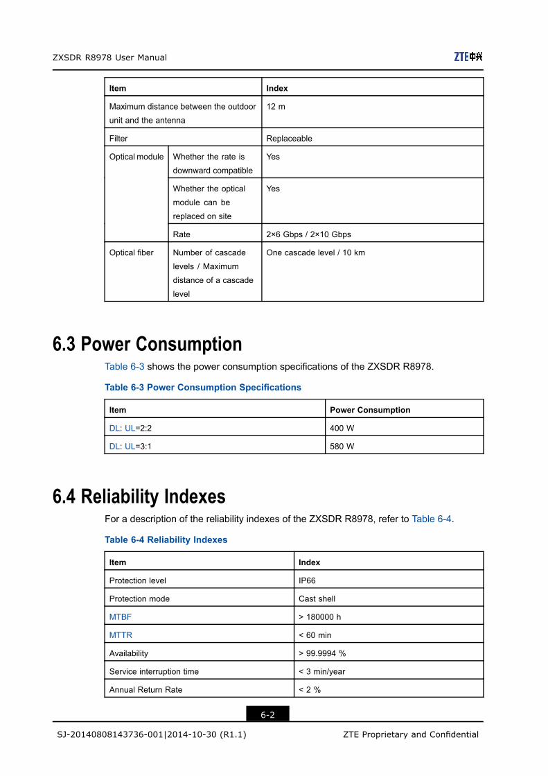
6.3 Power ConsumptionTable 6-3 shows the power consumption specifications of the ZXSDR R8978.
Table 6-3 Power Consumption Specifications
Item Power Consumption
DL: UL=2:2 400 W
DL: UL=3:1 580 W
6.4 Reliability IndexesFor a description of the reliability indexes of the ZXSDR R8978, refer to Table 6-4.
Table 6-4 Reliability Indexes
Item Index
Protection level IP66
Protection mode Cast shell
MTBF > 180000 h
MTTR < 60 min
Availability > 99.9994 %
Service interruption time < 3 min/year
Annual Return Rate < 2 %
6-2
SJ-20140808143736-001|2014-10-30 (R1.1) ZTE Proprietary and Confidential

Chapter 6 Technical Specifications
6.5 Grounding RequirementIn practical applications, the grounding resistance must be less than 10 Ω.
6.6 Lightening and Surge ProtectionTable 6-5 shows the lightening protection specification of the ZXSDR R8978.
Table 6-5 Lightening Protection Specification
Item Current
Lightening protection specification 20 kA
6-3
SJ-20140808143736-001|2014-10-30 (R1.1) ZTE Proprietary and Confidential

ZXSDR R8978 User Manual
This page intentionally left blank.
6-4
SJ-20140808143736-001|2014-10-30 (R1.1) ZTE Proprietary and Confidential

Chapter 7Environment RequirementsTable of Contents
Power Supply Requirements ......................................................................................7-1Operating Environment...............................................................................................7-1Storage Environment..................................................................................................7-2
7.1 Power Supply RequirementsTable 7-1 shows the requirements for the power supply of the ZXSDR R8978.
Table 7-1 Power Requirements
Item Requirement
DC power supply -48 V DC (fluctuation range: -57 V DC to –37 V DC)
The DC power supply must support the anti-reverse connection and
over-current protection functions.
AC power supply 100 V AC/110 V AC/220 V AC (fluctuation range: 90 VAC to 290 V AC)
If the AC power supply is used, the AC power needs to be converted into DC
power through the AC power lightening protection box and then connected
to the ZXSDR R8978.
7.2 Operating EnvironmentThe ZXSDR R8978 can operate properly in the following conditions:
Climatic Environment Condition
Item Description
Lowed temperature -40 ℃
Highest temperature 55 ℃
Lowest relative humidity 2 %RH
Highest relative humidity 100 %RH
Temperature change rate 0.5 ℃/min
Lowest atmospheric pressure 70 kPa
Highest atmospheric pressure 106 kPa
7-1
SJ-20140808143736-001|2014-10-30 (R1.1) ZTE Proprietary and Confidential

ZXSDR R8978 User Manual
Item Description
Solar radiation 1120 W/m2
Condensation Allowed
Precipitation (rain, snow, and hail) Allowed
Humidity Wet surface is allowed
Freezing and frost Allowed
Biological Environment Condition
Item Description
Plants Mold and fungus are allowed.
Animals Rodents and other animals that damage the product are allowed, except
termites
Chemical Substance Environment Condition
Item Description
Salt fog Allowed
7.3 Storage EnvironmentTo ensure normal operation after installation, the ZXSDR R8978 should be stored in apackage in a place with good protection.
Climatic Environment Condition
Item Description
Lowed temperature -55 ℃
Highest temperature 70 ℃
Lowest relative humidity 10 %RH
Highest relative humidity 100 %RH
Temperature change rate 1 ℃/min
Lowest atmospheric pressure 70 kPa
Highest atmospheric pressure 106 kPa
Solar radiation 1120 W/m2
Condensation Allowed
Precipitation (rain, snow, and hail) Allowed
Humidity Wet surface is allowed
7-2
SJ-20140808143736-001|2014-10-30 (R1.1) ZTE Proprietary and Confidential

Chapter 7 Environment Requirements
Item Description
Freezing and frost Allowed
Biologic Environment Condition
Item Description
Plants Mold and fungus are allowed.
Animals Rodents and other animals that damage the product are allowed, except termites
Chemical Substance Environment Condition
Item Description
Salt fog Allowed
7-3
SJ-20140808143736-001|2014-10-30 (R1.1) ZTE Proprietary and Confidential
ZXSDR R8978 User Manual
This page intentionally left blank.
7-4
SJ-20140808143736-001|2014-10-30 (R1.1) ZTE Proprietary and Confidential

FiguresFigure 2-1 Position of the RRU in a Network............................................................. 2-1
Figure 2-2 External View........................................................................................... 2-3
Figure 2-3 External Interfaces................................................................................... 2-5
Figure 2-4 Chain Networking .................................................................................... 2-6
Figure 2-5 Star Networking ....................................................................................... 2-7
Figure 3-1 System Structure ..................................................................................... 3-1
Figure 3-2 Product Composition................................................................................ 3-2
Figure 3-3 LED Indicators ......................................................................................... 3-3
Figure 3-4 Protective Grounding Cable ..................................................................... 3-5
Figure 3-5 Connection of the Protective Grounding Cable......................................... 3-6
Figure 3-6 DC Power Input Cable ............................................................................. 3-7
Figure 3-7 Connection of DC Power Input Cable....................................................... 3-9
Figure 3-8 Connection of the LMT/TST Interface Cable .......................................... 3-10
Figure 3-9 Optical Fiber .......................................................................................... 3-11
Figure 3-10 Connection of the Optical Fiber............................................................ 3-11
Figure 3-11 Antenna Feeder Interface Cable........................................................... 3-12
Figure 3-12 Connection of the Antenna Feeder Interface Cable.............................. 3-12
Figure 3-13 CAL Interface Cable............................................................................. 3-13
Figure 3-14 Connection of the CAL Interface Cable ................................................ 3-14
Figure 3-15 External Cable Connection .................................................................. 3-15
Figure 3-16 Software Composition.......................................................................... 3-16
Figure 4-1 ZTE Technical Support Contact Information ............................................. 4-2
Figure 4-2 Power-on Flow......................................................................................... 4-4
Figure 4-3 Connecting the RF cable.......................................................................... 4-9
Figure 4-4 Waterproof Treatment ............................................................................ 4-10
Figure 5-1 Junction Box ............................................................................................ 5-1
Figure 5-2 Junction Box Installation .......................................................................... 5-2
Figure 5-3 Interfaces and Cable Connection ............................................................. 5-3
Figure 5-4 External View........................................................................................... 5-4
Figure 5-5 Installation Modes.................................................................................... 5-5
Figure 5-6 Interfaces and Cable Connection ............................................................. 5-5
I
SJ-20140808143736-001|2014-10-30 (R1.1) ZTE Proprietary and Confidential

Figures
This page intentionally left blank.
II
SJ-20140808143736-001|2014-10-30 (R1.1) ZTE Proprietary and Confidential

TablesTable 2-1 Key Features of the ZXSDR R8978 S2300................................................ 2-3
Table 2-2 Key Features of the ZXSDR R8978 S2600................................................ 2-4
Table 2-3 Key Features of the ZXSDR R8978 S2600M............................................. 2-4
Table 2-4 External Interface Description.................................................................... 2-5
Table 3-1 Subsystem Description.............................................................................. 3-1
Table 3-2 Indicator Descriptions ................................................................................ 3-4
Table 4-1 Fault Location Methods ............................................................................. 4-2
Table 4-2 Equipment Maintenance............................................................................ 4-3
Table 4-3 Power-on Steps......................................................................................... 4-5
Table 4-4 Power-off Steps......................................................................................... 4-5
Table 5-1 Junction Box Specifications ....................................................................... 5-2
Table 5-2 Specifications of the AC Power Lightening Protection Box......................... 5-4
Table 6-1 Physical Specifications .............................................................................. 6-1
Table 6-2 Performance Indexes ................................................................................ 6-1
Table 6-3 Power Consumption Specifications............................................................ 6-2
Table 6-4 Reliability Indexes ..................................................................................... 6-2
Table 6-5 Lightening Protection Specification ............................................................ 6-3
Table 7-1 Power Requirements ................................................................................. 7-1
III
SJ-20140808143736-001|2014-10-30 (R1.1) ZTE Proprietary and Confidential

Tables
This page intentionally left blank.
IV
SJ-20140808143736-001|2014-10-30 (R1.1) ZTE Proprietary and Confidential

GlossaryAISG- Antenna Interface Standards Group
ALM- Alarm
ANT- Antenna
BBU- Base Band Unit
BSP- Board Support Package
CFR- Crest Factor Reduction
DIF- Digital IF
DL- Down Link
DPD- Digital Pre-Distortion
EAM- Electro-Absorption Modulation
GPS- Global Positioning System
IP- Internet Protocol
LMT- Local Maintenance Terminal
LTE- Long Term Evolution
MIMO- Multiple-Input Multiple-Output
MTBF- Mean Time Between Failures
MTTR- Mean Time To Recovery
V
SJ-20140808143736-001|2014-10-30 (R1.1) ZTE Proprietary and Confidential

ZXSDR R8978 User Manual
OAM- Operation, Administration and Maintenance
OS- Operating System
OSS- Operation Support Subsystem
RF- Radio Frequency
RGPS- Remote GPS
RRU- Remote Radio Unit
SDR- Software Defined Radio
TCP- Transmission Control Protocol
TD- Time Division
TELNET- Telecommunication Network Protocol
TRX- Transceiver
UE- User Equipment
UL- Uplink
VSWR- Voltage Standing Wave Ratio
eNodeB- Evolved NodeB
VI
SJ-20140808143736-001|2014-10-30 (R1.1) ZTE Proprietary and Confidential