
ZXSDR BS8900 GU360 (V4.00) Outdoor GSM&UMTS Dual Mode Macro Node B Maintenance Guide
117
ZXSDR BS8900 GU360 Outdoor GSM&UMTS Dual Mode Macro Node B Maintenance Guide Version 4.00 ZTE CORPORATION ZTE Plaza, Keji Road South, Hi-Tech Industrial Park, Nanshan District, Shenzhen, P. R. China 518057 Tel: (86) 755 26771900 Fax: (86) 755 26770801 URL: http://ensupport.zte.com.cn E-mail: [email protected]
-
Upload
prashant-mara -
Category
Documents
-
view
44 -
download
7
description
ZTe SDR maintanance mannual
Transcript of ZXSDR BS8900 GU360 (V4.00) Outdoor GSM&UMTS Dual Mode Macro Node B Maintenance Guide

ZXSDR BS8900 GU360Outdoor GSM&UMTS Dual Mode Macro Node B
Maintenance Guide
Version 4.00
ZTE CORPORATIONZTE Plaza, Keji Road South,Hi-Tech Industrial Park,Nanshan District, Shenzhen,P. R. China518057Tel: (86) 755 26771900Fax: (86) 755 26770801URL: http://ensupport.zte.com.cnE-mail: [email protected]

LEGAL INFORMATION
Copyright © 2006 ZTE CORPORATION.
The contents of this document are protected by copyright laws and international treaties. Any reproduction or distribution ofthis document or any portion of this document, in any form by any means, without the prior written consent of ZTE CORPO-RATION is prohibited. Additionally, the contents of this document are protected by contractual confidentiality obligations.
All company, brand and product names are trade or service marks, or registered trade or service marks, of ZTE CORPORATIONor of their respective owners.
This document is provided “as is”, and all express, implied, or statutory warranties, representations or conditions are dis-claimed, including without limitation any implied warranty of merchantability, fitness for a particular purpose, title or non-in-fringement. ZTE CORPORATION and its licensors shall not be liable for damages resulting from the use of or reliance on theinformation contained herein.
ZTE CORPORATION or its licensors may have current or pending intellectual property rights or applications covering the subjectmatter of this document. Except as expressly provided in any written license between ZTE CORPORATION and its licensee,the user of this document shall not acquire any license to the subject matter herein.
ZTE CORPORATION reserves the right to upgrade or make technical change to this product without further notice.
Users may visit ZTE technical support website http://ensupport.zte.com.cn to inquire related information.
The ultimate right to interpret this product resides in ZTE CORPORATION.
Revision History
Revision No. Revision Date Revision Reason
R1.0 20090205 First edition
Serial Number: sjzl20090458

Content
About This Manual.............................................. i
Safety Instruction .............................................1Safety Overview............................................................. 1
Safety Symbols .............................................................. 1
Safety Specifications....................................................... 3
Routine Maintenance.........................................7Overview....................................................................... 7
Purpose..................................................................... 7
Methods .................................................................... 7
Precautions................................................................ 8
Daily Maintenance .......................................................... 9
Daily Routine Maintenance Items .................................. 9
Handling Alarm .........................................................10
Querying and Handling Current Alarms ................10
Querying and Analyzing Past 24-Hour History
Alarms .................................................12
Querying Real-Time Status of Each Cell ........................14
Analyzing Daily Cell Performance Report Data................15
Handling Common Faults ............................................17
Handling Subscriber Complaints ..................................17
Monthly Maintenance .....................................................18
Monthly Routine Maintenance Items .............................18
Analyzing Alarm Frequency .........................................18
Analyzing Monthly Cell Performance Report Data ...........21
Main Equipment Maintenance ......................................23
Checking Cabinet Power Supply ..........................23
Checking Cabinet Grounding...............................24
Checking Cabinet Protection ...............................24
Testing Heat Exchanger .....................................25
Cable Connection Checking .........................................25
Checking Trunk Cable Connection........................25
Checking Fiber Connection .................................26
Checking Data Cable and Monitoring Cable
Connections ..........................................26
Spare Part Checking...................................................26
Checking Storage Environment of Spare
Parts ....................................................26
Checking Amount of Spare Parts .........................27
Quarterly Maintenance ...................................................27
Quarterly Routine Maintenance Items...........................27
Testing Call, Coverage, and Handover...........................28
Main Equipment Maintenance ......................................28
Checking Fan’s Running Status ...........................28
Checking Board’s Running Status ........................28
Heat Exchanger Maintenance..............................34
Cable Connection Checking .........................................35
Checking RF Cable Connection ............................35
Checking GPS Cable Connection..........................35
Semiyearly Maintenance.................................................36
Biannual Routine Maintenance Items ............................36
Equipment Cleaning ...................................................36
Cleaning Fan Subrack ........................................36
Board Diagnosis and Test............................................37
Yearly Maintenance........................................................38
Yearly Routine Maintenance Items ...............................38
BTS Testing ..............................................................39
Measuring Power Amplifier’s Output Power ...........39
Measuring SWR ................................................40
Testing CC Board Changeover......................................40
Grounding Checking...................................................42
Checking Lightning Protector ..............................42
Checking Grounding Cable .................................43
Testing Grounding Resistance .............................43
Antenna Feeder System Checking ................................43
Checking Antenna Feeder Interface .....................43
Checking Firmness of Antenna and Tower
Amplifier...............................................44
Checking Directional Antenna Tilt ........................44
Checking Waterproof Status of Antenna Feeder
Connectors and Lightning Protection
Grounding Clips .....................................46

Other Checking .........................................................46
Checking Iron Tower..........................................46
Checking Pole...................................................46
Checking Running Status of Batteries ..................47
Emergency Maintenance..................................49Overview......................................................................49
Emergency Maintenance Scenarios...............................49
Emergency Maintenance Flow......................................49
Emergency Maintenance Precautions ............................52
Emergency Process........................................................53
Automatic Active-Standby Changeover .........................53
Manual Active-Standby Changeover .............................53
Resetting Power-Down Board ......................................54
Checking Whether Fan Is Running Normally ..................55
Service Recover ............................................................56
Service Resuming Flow...............................................56
Service Recover Procedure..........................................58
Checking Whether PM Is Normal .........................58
Repairing Power Supply System ..........................58
Checking Power Supply of Main Boards ................58
Checking Whether Service Boards Run
Normally...............................................58
Resetting/Replacing Board..................................59
Checking Whether Fault Is due to Configuration
Data Modification ...................................59
Resuming Original Configuration Data..................59
Collecting Fault Information................................60
Troubleshooting ..............................................61Common Troubleshooting Process ....................................61
Common Service Troubleshooting ....................................63
Low Call Completion Ratio...........................................63
Poor Call Quality........................................................64
Slow to Access the Internet ........................................66
Common Equipment Troubleshooting................................66
Temperature of RU Board Being High............................66
B121 DC Power Distribution Unit Fault ..........................67
B121 AC Power Distribution Unit Fault ..........................70
B121 Monitoring Unit Fault..........................................75
B121 Rectifier Fault....................................................75
Heat Exchanger Fault .................................................77

Environment Alarm unable to Be Reported ....................77
Part Replacement............................................79Replaceable Part List ......................................................79
Board Replacement........................................................80
Board Replacement Instructions ..................................80
Replacing RU ............................................................81
Replacing PM ............................................................83
Replacing CC/FS/UBPG/BPC ........................................84
Replacing SA.............................................................86
Replacing FA .............................................................86
Subrack Replacement.....................................................88
Subrack Replacement Instructions ...............................88
Replacing B121 Power Supply......................................89
Replacing PDM Subrack ..............................................90
Replacing Fan Subrack ...............................................91
Replacing Battery ......................................................92
Replacing Heat Exchanger...........................................93
Replacing Lightning Protection Subrack.........................94
Replacing BBU...........................................................95
Data Record Forms..........................................97Daily Maintenance Record Form.......................................97
Monthly Maintenance Record Form...................................99
Quarterly Maintenance Record Form............................... 100
Biannual Maintenance Record Form................................ 101
Yearly Maintenance Record Form ................................... 102
Part Replacement Data Record Form .............................. 104
Emergency Troubleshooting Record Form........................ 105
Figures ..........................................................107
Tables ...........................................................109

About This Manual
Purpose This manual introduces maintenance methods of ZXSDR BS8900GU360 (V4.00) Outdoor GSM&UMTS Dual Mode Macro Node B sys-tem (BS8900 GU360 for short), including routine maintenance,emergency maintenance, troubleshooting, and part replacement.It also provides tables for recording equipment maintenance infor-mation.
The BS8900 GU360 documents includes the following manuals:
ZXSDR BS8900 GU360(V4.00) Outdoor GSM&UMTS Dual ModeMacro Node B Documentation Guide
ZXSDR BS8900 GU360(V4.00) Outdoor GSM&UMTS Dual ModeMacro Node B System Description
ZXSDR BS8900 GU360(V4.00) Outdoor GSM&UMTS Dual ModeMacro Node B Hardware Description
ZXSDR BS8900 GU360(V4.00) Outdoor GSM&UMTS Dual ModeMacro Node B Hardware Installation Guide
ZXSDR BS8900 GU360(V4.00) Outdoor GSM&UMTS Dual ModeMacro Node B Configuration Guide
ZXSDR BS8900 GU360(V4.00) Outdoor GSM&UMTS Dual ModeMacro Node B Configuration Parameter Reference
ZXSDR BS8900 GU360(V4.00) Outdoor GSM&UMTS Dual ModeMacro Node B Alarm Code Reference
ZXSDR BS8900 GU360(V4.00) Outdoor GSM&UMTS Dual ModeMacro Node B Maintenance Guide
What Is in ThisManual
This guide contains the following chapters.
Section Summary
Chapter 1, SafetyInstruction
Gives safety instruction for BS8900 GU360maintenance.
Chapter 2, RoutineMaintenance
Introduces BS8900 GU360 routine maintenanceitems and methods.
Chapter 3,EmergencyMaintenance
Introduces BS8900 GU360 emergencymaintenance scenario, flow, handling methods,and the service resuming ways.
Chapter 4,Troubleshooting
Introduces common troubleshooting methodsfor BS8900 GU360.
Chapter 5, PartReplacement
Introduces methods of part replacement forBS8900 GU360.
Appendix A, DataRecord Forms
Gives maintenance record forms of BS8900GU360 for keeping the equipment maintenanceinformation.
Confidential and Proprietary Information of ZTE CORPORATION i
ZXSDR BS8900 GU360 Maintenance Guide
This page is intentionally blank.
ii Confidential and Proprietary Information of ZTE CORPORATION

C h a p t e r 1
Safety Instruction
Table of ContentsSafety Overview................................................................. 1Safety Symbols .................................................................. 1Safety Specifications........................................................... 3
Safety OverviewOnly qualified professional staff who has received BSS training caninstall, operate and maintain the equipment.
BSS maintenance personnel must:
Master basic theories of BSS system
Be familiar with BSS system principles and networking
Have network optimization skills
During the installation, operation and maintenance of the equip-ment, one should strictly abide by all the safety rules and relatedoperation procedures on the site to avoid body injuries or equip-ment damages. The safety precautions introduced in this manualare only supplementary to the local safety rules.
ZTE assumes no responsibility for consequences resulting from vi-olation of the general specifications for safety operations or safetystandards for design, production, and equipment usage.
Safety SymbolsTable 1 lists safety symbols.
TABLE 1 SAFETY SYMBOLS DESCRIPTION
Safety Symbol Meaning
Universal alerting symbol:General safety attentions.
Confidential and Proprietary Information of ZTE CORPORATION 1

ZXSDR BS8900 GU360 Maintenance Guide
Safety Symbol Meaning
Electrostatic: The device may besensitive to static electricity.
Electric shock: Risk of electricshock.
Scald: Be aware of scald.
Laser: Beware of strong laserbeam.
Microwave: Beware of strongelectromagnetic field.
Amongst these safety symbols, the universal alarm symbols areclassified into four levels: danger, warning, caution, and note. Theformats and meanings of the four levels are described as below:
Danger:
Indicates a potentially hazardous situation which, if not avoided,will result in death or serious injury of people, or equipment dam-ages and breakdown.
Warning:
Indicates a potentially hazardous situation which, if not avoided,could result in serious injuries, or equipment damages or interrup-tion of main services.
Caution:
Indicates a potentially hazardous situation which, if not avoided,could result in serious injuries, or equipment damages or interrup-tion of part services.
Note:
Indicates a potentially hazardous situation which, if not avoided,could result in injuries, or equipment damages or interruption ofpart services.
2 Confidential and Proprietary Information of ZTE CORPORATION

Chapter 1 Safety Instruction
Safety SpecificationsElectrical Safety
Electric Shock:
Never install or uninstall power cables while they are live becausewhen touched with a conductor may produce sparks, resulting infire or damage to eyes.
Do shut off power supply before connecting or disconnecting apower cable.
Before connecting a cable, make sure that the cable and its labelmeet the actual installation requirements.
Warning:
It is not allowed to drill cabinet holes without permission. Unqual-ified drilling could damage wiring inside the cabinet. Additionally,the metal pieces inside the cabinet created by drilling could resultin a shorted circuit board.
Antistatic
Electrostatic:
Static electricity produced by human body can damage static-sen-sitive components on circuit board, such as large-scale integratedcircuits.
Friction caused by human body activities is the root cause of elec-trostatic charge accumulation. Static voltage carried by a humanbody in a dry environment can be up to 30 kV, and can remain inthere for a long time. An operator with static electricity may dis-charge electricity through a component when he/she touches theconductor and causing damage.
Wear an antistatic wrist strap (the other end of wrist strap must bewell grounded) before touching the equipment or holding a plug-inboard, circuit board, Integrated Circuit (IC) chip or other devices,to prevent human static electricity from damaging sensitive com-ponents.
Confidential and Proprietary Information of ZTE CORPORATION 3

ZXSDR BS8900 GU360 Maintenance Guide
Laser
Laser:
Avoid looking straight at the laser beam from the outlet of theoptical transceiver or inside the optical fiber to avoid eye damage.
High Temperature
Danger:
Avoid touching the surface area of some devices due to high tem-perature to avoid a scald injury.
Fans
Warning:
Do not put fingers or any tools in the running fan to avoid an injury.Keep tools away from the running fan.
Sticking finger inside a running fan may cause hurt.
Put parts, screws, and tools away from the fan when replacingrelated parts, to avoid damage to the fan or related devices.
Keep fingers and board away from the fan when replacing devicesaround the fan, to avoid damage to the equipment or fingers.
Hoisting HeavyObjects
Warning:
Do not walk or stay under the hoisted objects during hoisting op-erations.
Ensure a proper hoisting capability of the hoister when disas-sembling heavy equipment moving, and replacing equipment.
The operator must receive the training and qualification forhoisting operations. Inspect and complete the hoisting toolsbefore getting into service.
Make sure to fix the hoisting tools firmly on a sufficiently se-cured object or wall before the hoisting operation.
Use brief oral instructions during the hoisting operations to pre-vent mistaken operation.
Plugging/Unplug-ging Modules
The modules mentioned in this document include front board, rearboard, and fan module.
4 Confidential and Proprietary Information of ZTE CORPORATION

Chapter 1 Safety Instruction
Caution:
Avoid inserting a module forcibly. Otherwise, the pin on thebackplane may bent.
Align the module with the guide rail and push it gently to thebackplane. Plug the module properly into the slot to preventshort circuit due to contact between the module and the circuitsurface.
Avoid touching the circuits, components, connectors, and ca-ble troughs when holding a module.
RF module turns hot when running. Avoid being scalded whenplugging and unplugging an RF module.
Personnel
Caution:
Non-professionals can only perform maintenance inside the equip-ment with the presence or under instructions of professionals onsite.
Replacing any parts or altering the equipment may result in un-expected dangers. Therefore, avoid replacing any parts or alter-ing the equipment unless authorized. Contact ZTE in case of anyqueries.
Confidential and Proprietary Information of ZTE CORPORATION 5

ZXSDR BS8900 GU360 Maintenance Guide
This page is intentionally blank.
6 Confidential and Proprietary Information of ZTE CORPORATION
C h a p t e r 2
Routine Maintenance
Table of ContentsOverview........................................................................... 7Daily Maintenance .............................................................. 9Monthly Maintenance .........................................................18Quarterly Maintenance .......................................................27Semiyearly Maintenance.....................................................36Yearly Maintenance............................................................38
OverviewPurpose
Routine maintenance means checking the equipment status pe-riodically to find and solve problems in time to prevent potentialdamages or faults.
Methods
The following lists common methods for locating faults during rou-tine maintenance:
Alarm and notification check
Query equipment alarms and notifications at background, per-form analysis to determine whether there is anything abnor-mal, and implement appropriate handling.
Equipment running status check
Query the site’s running status at background, such as the cell’sreal-time status, perform analysis and implement appropriatehandling.
Performance index check
Query various site performance indices at background, analyzethese indices and implement appropriate handling.
Main equipment check
Confidential and Proprietary Information of ZTE CORPORATION 7

ZXSDR BS8900 GU360 Maintenance Guide
Check the site equipment’s running conditions, such as theequipment’s power supply and the board’s running status.
Cable connection check
Check various cable connections and make sure that cable la-bels are pasted appropriately.
Grounding and lightning protection check
Check the site’s lightning protection system and the groundingsystem to make sure that they are reliable.
Antenna feeder system check
Check the feeder cable connection of the site’s antenna feedersystem, the waterproof condition, and the antenna downtilt.
Spare part check
Check the amount of the spare parts and the storage environ-ment.
Site test
Perform the coverage test and the handover test for the site,measure the site’s power and SWR, and handle problems intime if there is any.
Board diagnosis and test
Perform diagnosis and test for boards at background.
Daily fault handling
Perform analysis for daily faults detected and handle them intime.
Equipment cleaning
Clean the equipment periodically to avoid dust accumulatingand guarantee the equipment’s normal running.
Precautions
The following matters should be noticed during routine mainte-nance:
1. Ensure the stability and reliability of the primary power supplyand check the system ground and lightning protection groundperiodically. Before stormy season and after thunder storms,check the lightning protection system to make sure all facilitiesare in good conditions.
2. Regulate the routine work of maintenance personnel. Keepa detailed duty log to provide details about system opera-tion, version, data change, upgrading, and troubleshooting onday-to-day basis for follow-up analysis and troubleshooting inthe event of a fault. Also keep a shift record to specify theresponsibility clearly.
3. Maintenance personnel should be trained to grasp certainknowledge related to equipment and network before perform-ing the routine maintenance. During maintenance operations,it is necessary to follow the instructions described in relatedmanuals of BS8900 GU360. Before touching the equipment,
8 Confidential and Proprietary Information of ZTE CORPORATION

Chapter 2 Routine Maintenance
maintenance personnel must wear antistatic wrist strap toavoid accidents.
4. It is strictly forbidden to run the signaling tracing program dur-ing daytime when the traffic is heavy. Signaling tracing canonly be performed in low-traffic hours with permission by thelocal ZTE office.
5. Check the spare parts periodically to guarantee that they are ingood conditions without being affected by moisture. Make surethat there is sufficient stock of commonly used spare parts.Keep the spare parts separate from those faulty parts and labelthem for identification.
6. Handle fault as soon as possible. Contact the local ZTE officefor any problem that cannot be resolved.
7. Place the local ZTE office’s contact information at a visible placeand make it known to all maintenance personnel. Update thecontact information in time.
Daily MaintenanceDaily Routine Maintenance Items
Table 2 lists the daily routine maintenance items.
TABLE 2 DAILY ROUTINE MAINTENANCE ITEMS
Category Items
Querying and handling currentalarms
Querying and analyzing the past24–hour history alarmsAlarms and notifications
Querying and analyzing the past24–hour history notifications
Running status Querying real-time BTS cells sta-tus
Performance indices Analyzing daily cell performancereport data
Handling common faultsTroubleshooting
Handling subscriber complaints
Confidential and Proprietary Information of ZTE CORPORATION 9

ZXSDR BS8900 GU360 Maintenance Guide
Handling Alarm
Querying and Handling Current Alarms
Prerequisites Communication between the NetNumen M31 client and theNetNumen M31 server is normal.
Connections between the NetNumen M31 server and networkelements are normal.
Steps 1. Log in to the NetNumen M31 client.2. Click View > Fault Management, the Fault Management
interface appears, as shown in Figure 1.
FIGURE 1 FAULT MANAGEMENT INTERFACE
3. Right-click on the site node to be queried in the left ResourceView, select Show current alarms > Show all currentalarms, as shown in Figure 2.
10 Confidential and Proprietary Information of ZTE CORPORATION

Chapter 2 Routine Maintenance
FIGURE 2 DISPLAYING CURRENT ALARMS
4. View the site’s current alarms in the right pane, as shown inFigure 3.
FIGURE 3 VIEWING SITE’S CURRENT ALARMS
ReferenceStandard
The site has no abnormal alarm in the fault management interface.
AbnormalityHandling
Double-click an alarm to obtain the alarm details in the Detailsdialog box, as shown in Figure 4. Handle the alarm accordingto suggestions given in the Maintenance Suggestion tab in thedialog.
Confidential and Proprietary Information of ZTE CORPORATION 11

ZXSDR BS8900 GU360 Maintenance Guide
FIGURE 4 ALARM DETAILS DIALOG BOX
Precautions None
Querying and Analyzing Past 24-Hour HistoryAlarms
Prerequisites Communication between the NetNumen M31 client and theNetNumen M31 server is normal.
Connections between the NetNumen M31 server and networkelements are normal.
Steps 1. Log in to the NetNumen M31 client.2. Click View > Fault Management, the Fault Management
interface appears.3. Click Query > View History Alarms, the History Alarms
Query Conditions tab appears on the right.4. In the History Alarms Query Conditions tab, click theQuick
Search button, as shown in Figure 5.
12 Confidential and Proprietary Information of ZTE CORPORATION

Chapter 2 Routine Maintenance
FIGURE 5 CLICKING QUICK SEARCH BUTTON
5. Set query conditions in the Query History Alarm dialog box.Select System Type and Location for the site to be queried,as shown in Figure 6.
FIGURE 6 SETTING QUERY CONDITION - LOCATION
Confidential and Proprietary Information of ZTE CORPORATION 13

ZXSDR BS8900 GU360 Maintenance Guide
6. Select Restore Time and set it to be the past 24 hours, asshown in Figure 7.
FIGURE 7 SETTING QUERY CONDITION - RESTORE TIME
7. Click the OK button after setting query conditions, and thesystem will display all history alarms during the past 24 hours.
ReferenceStandard
The alarm query result is displayed normally. There is no abnormalalarm and no frequently occurring alarm .
AbnormalityHandling
Perform analysis for abnormal alarms and alarms that frequentlyoccur. Find out causes for these alarms and handle frequentlyoccurring alarms in time.
Precautions None
Querying Real-Time Status of EachCell
Prerequisites Communication between the NetNumen M31 client and theNetNumen M31 server is normal.
Connections between the NetNumen M31 server and networkelements are normal.
Steps 1. Log in to the NetNumen M31 client.
14 Confidential and Proprietary Information of ZTE CORPORATION

Chapter 2 Routine Maintenance
2. Start the NE agent.3. In Physical View of the Topology Management tab, click
NE Agent > Dynamic Data Management.4. On the left pane, right-click on the Base station sys-
tem/logic site > Cell, select Channel Statistics Query.The system displays the service channel and signaling channelconfigurations and real-time status in the current cell.
5. Click Cell > Transceiver, and right-click on Refresh, the real-time status of all channels of the transceiver will be displayed.
ReferenceStandard
The channel status in the cell is normal, there is no blocked chan-nel. The real-time occupation of voice channel exists.
AbnormalityHandling
For sites with blocked channels, perform handling according tothe site alarms reported in Fault Management. For sites with-out channel occupation or abnormal channel occupation (such aschannel being released once being occupied), perform handlingaccording to information obtained in Fault Management and sig-naling tracing.
Precautions Before using Dynamic Data Management, the NE agent mustbe started first.
Analyzing Daily Cell PerformanceReport Data
Prerequisites Communication between the NetNumen M31 client and theNetNumen M31 server is normal.
Connections between the NetNumen M31 server and networkelements are normal.
Steps 1. Log in to the NetNumen M31 client.2. Click View > Performance Management, the Performance
Management interface appears.3. Click Performance Management > Performance data
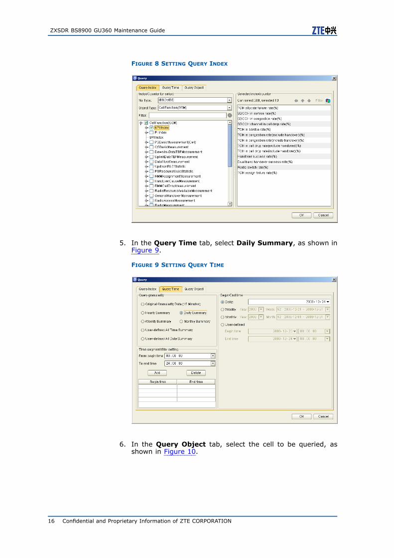
query, the Query dialog box appears.4. In the Query dialog box, select the Query Index tab, set
the Ne Type to be IBSCMEID and the Object Type to beCellFunction(GSM). Select indices or measurement types tobe queried, as shown in Figure 8.
Confidential and Proprietary Information of ZTE CORPORATION 15
ZXSDR BS8900 GU360 Maintenance Guide
FIGURE 8 SETTING QUERY INDEX
5. In the Query Time tab, select Daily Summary, as shown inFigure 9.
FIGURE 9 SETTING QUERY TIME
6. In the Query Object tab, select the cell to be queried, asshown in Figure 10.
16 Confidential and Proprietary Information of ZTE CORPORATION

Chapter 2 Routine Maintenance
FIGURE 10 SETTING QUERY OBJECT
7. Click the OK button to analyze the query result.
ReferenceStandard
All performance indices in the query result are normal.
AbnormalityHandling
Perform relevant handling according to abnormal indices in thereport.
Precautions In the Query Index tab, the Object Type can also be set asIBTSTRX(GSM) or IBTSTS(GSM).
Handling Common Faults
Common fault handling involves handling fault indicated in alarmmessages, such as the transmission fault and board fault.
Handling Subscriber Complaints
Test and troubleshoot faults according to subscribers’ complaints.
Confidential and Proprietary Information of ZTE CORPORATION 17
ZXSDR BS8900 GU360 Maintenance Guide
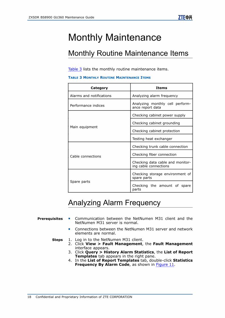
Monthly MaintenanceMonthly Routine Maintenance Items
Table 3 lists the monthly routine maintenance items.
TABLE 3 MONTHLY ROUTINE MAINTENANCE ITEMS
Category Items
Alarms and notifications Analyzing alarm frequency
Performance indices Analyzing monthly cell perform-ance report data
Checking cabinet power supply
Checking cabinet grounding
Checking cabinet protectionMain equipment
Testing heat exchanger
Checking trunk cable connection
Checking fiber connectionCable connections
Checking data cable and monitor-ing cable connections
Checking storage environment ofspare parts
Spare partsChecking the amount of spareparts
Analyzing Alarm Frequency
Prerequisites Communication between the NetNumen M31 client and theNetNumen M31 server is normal.
Connections between the NetNumen M31 server and networkelements are normal.
Steps 1. Log in to the NetNumen M31 client.2. Click View > Fault Management, the Fault Management
interface appears.3. Click Query > History Alarm Statistics, the List of Report
Templates tab appears in the right pane.4. In the List of Report Templates tab, double-click Statistics
Frequency By Alarm Code, as shown in Figure 11.
18 Confidential and Proprietary Information of ZTE CORPORATION

Chapter 2 Routine Maintenance
FIGURE 11 DOUBLE-CLICKING STATISTICS FREQUENCY BY ALARM CODE
5. Set query conditions in the Parameter Input Box-StatisticsFrequency By Alarm Code dialog box. Set System Typeand Location for the site to be queried, as shown in Figure12.
Confidential and Proprietary Information of ZTE CORPORATION 19

ZXSDR BS8900 GU360 Maintenance Guide
FIGURE 12 SETTING QUERY CONDITION - LOCATION
6. Select Happen Time and set it to be the past one month, asshown in Figure 13.
20 Confidential and Proprietary Information of ZTE CORPORATION

Chapter 2 Routine Maintenance
FIGURE 13 SETTING QUERY CONDITION - HAPPEN TIME
7. Click the OK button after setting query conditions to analyzethe alarm frequency.
ReferenceStandard
The alarm frequency query result is output normally.
AbnormalityHandling
Perform analysis for alarms that occur frequently.
Precautions In the List of Report Templates tab, user can also select othertemplate to perform query and analysis for history alarms.
Analyzing Monthly Cell PerformanceReport Data
Prerequisites Communication between the NetNumen M31 client and theNetNumen M31 server is normal.
Connections between the NetNumen M31 server and networkelements are normal.
Steps 1. Log in to the NetNumen M31 client.2. Click View > Performance Management, the Performance
Management interface appears.
Confidential and Proprietary Information of ZTE CORPORATION 21

ZXSDR BS8900 GU360 Maintenance Guide
3. Click Performance management > Performance dataquery, the Query dialog appears.
4. In the Query dialog box, select the Query Index tab, setthe Ne Type to be IBSCMEID and the Object Type to beCellFunction(GSM). Select indices or measurement types tobe queried, as shown in Figure 14.
FIGURE 14 SETTING QUERYING INDEX
5. In the Query Time tab, select Monthly Summary, as shownin Figure 15.
FIGURE 15 SETTING QUERY TIME
22 Confidential and Proprietary Information of ZTE CORPORATION

Chapter 2 Routine Maintenance
6. In the Query Object tab, select the cell to be queried, asshown in Figure 16.
FIGURE 16 SETTING QUERY OBJECT
7. Click the OK button to analyze the query result.
ReferenceStandard
All performance indices in the query result are normal.
AbnormalityHandling
Perform relevant handling for abnormal indices in the report.
Precautions In the Query Index tab, the Object Type can also be set asIBTSTRX(GSM) or IBTSTS(GSM).
Main Equipment Maintenance
Checking Cabinet Power Supply
Prerequisites Prepare a multimeter for testing the power supply.
Steps 1. Check power input terminals and power output terminals of thepower distribution subrack to see whether they have normalsizes and good contact. Check whether there is any problemof corrosion, over-current, or over-temperature.
2. Check power input terminals, power output terminals, andpower sockets of each component inside the cabinet to seewhether they have normal sizes and good contact. Checkwhether there is any problem of corrosion, over-current, orover-temperature.
3. Use the multimeter to measure the power distribution sub-rack’s input voltage. Check whether the power cable is aging.
Confidential and Proprietary Information of ZTE CORPORATION 23

ZXSDR BS8900 GU360 Maintenance Guide
ReferenceStandard
1. All connection parts have good contact, and there is no problemof loosening or corrosion.
2. There is no equipment that has distorted appearance or theproblem of contacting part being hot for long term.
3. DC power nominal value: –48 V DC; allowed fluctuation range:–57 V DC ~ –40 V DC.
The DC power cable is not aging.
AbnormalityHandling
If the DC power supply is abnormal, check whether there is anyalarm of the power supply. Perform troubleshooting according tothe alarm indicator meanings and power supply equipment instruc-tions. Replace the DC power cable if it is aging.
Precautions None
Checking Cabinet Grounding
Prerequisites Prepare a grounding resistance tester before checking the cabinetgrounding.
Steps 1. Check connection terminals and fastening screws of all ground-ing cables inside the cabinet to see whether they have goodcontact. Check whether there is any problem of loosening orcorrosion.
2. Use the grounding resistance tester to measure grounding re-sistance of the equipment room.
ReferenceStandard
1. All connection parts have good contact, and there is no problemof loosening or corrosion.
2. The joint grounding resistance is less than 5 Ω; for specialdesign, the grounding resistance satisfies the design require-ment.
AbnormalityHandling
Replace damaged grounding cables or connection terminals, andfasten the screws. If the equipment room’s grounding resis-tance does not satisfy the design requirement, check whetherthe grounding downlead is firmly connected with the groundingnetwork.
Precautions None
Checking Cabinet Protection
Prerequisites None
Steps 1. Check the cabinet top and inside to see whether there is anyobject that is not the cabinet’s component.
2. Check the rodent-resistant net at the signal cable outlet oncabinet top or at cabinet bottom to see whether it is boundtightly and not damaged.
ReferenceStandard
1. On the cabinet top and inside the cabinet, there is no objectthat is not the cabinet’s component.
2. All rodent-resistance nets are bound tightly and not damaged.
AbnormalityHandling
On top of or inside the cabinet, remove object that is not the cab-inet’s component. Bind the rodent-resistance net tightly.
24 Confidential and Proprietary Information of ZTE CORPORATION
Chapter 2 Routine Maintenance
Precautions None
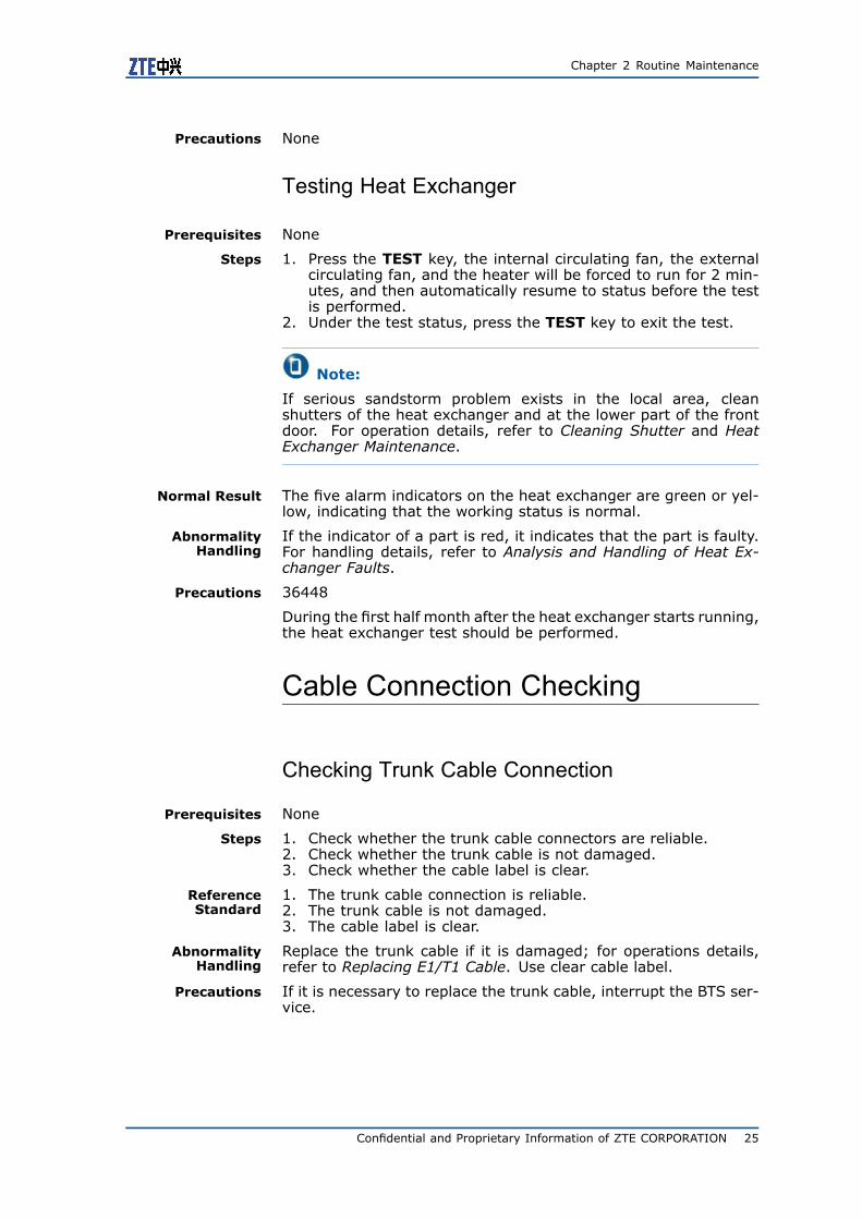
Testing Heat Exchanger
Prerequisites None
Steps 1. Press the TEST key, the internal circulating fan, the externalcirculating fan, and the heater will be forced to run for 2 min-utes, and then automatically resume to status before the testis performed.
2. Under the test status, press the TEST key to exit the test.
Note:
If serious sandstorm problem exists in the local area, cleanshutters of the heat exchanger and at the lower part of the frontdoor. For operation details, refer to Cleaning Shutter and HeatExchanger Maintenance.
Normal Result The five alarm indicators on the heat exchanger are green or yel-low, indicating that the working status is normal.
AbnormalityHandling
If the indicator of a part is red, it indicates that the part is faulty.For handling details, refer to Analysis and Handling of Heat Ex-changer Faults.
Precautions 36448
During the first half month after the heat exchanger starts running,the heat exchanger test should be performed.
Cable Connection Checking
Checking Trunk Cable Connection
Prerequisites None
Steps 1. Check whether the trunk cable connectors are reliable.2. Check whether the trunk cable is not damaged.3. Check whether the cable label is clear.
ReferenceStandard
1. The trunk cable connection is reliable.2. The trunk cable is not damaged.3. The cable label is clear.
AbnormalityHandling
Replace the trunk cable if it is damaged; for operations details,refer to Replacing E1/T1 Cable. Use clear cable label.
Precautions If it is necessary to replace the trunk cable, interrupt the BTS ser-vice.
Confidential and Proprietary Information of ZTE CORPORATION 25
ZXSDR BS8900 GU360 Maintenance Guide
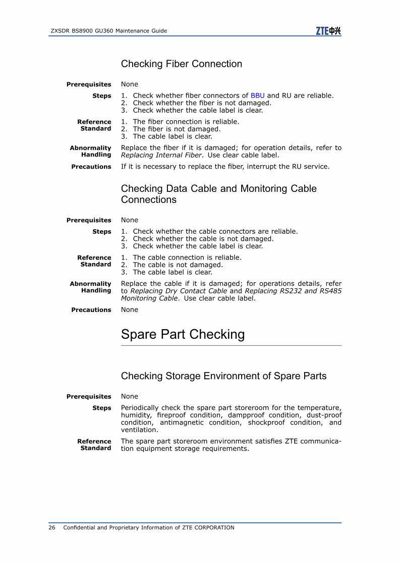
Checking Fiber Connection
Prerequisites None
Steps 1. Check whether fiber connectors of BBU and RU are reliable.2. Check whether the fiber is not damaged.3. Check whether the cable label is clear.
ReferenceStandard
1. The fiber connection is reliable.2. The fiber is not damaged.3. The cable label is clear.
AbnormalityHandling
Replace the fiber if it is damaged; for operation details, refer toReplacing Internal Fiber. Use clear cable label.
Precautions If it is necessary to replace the fiber, interrupt the RU service.
Checking Data Cable and Monitoring CableConnections
Prerequisites None
Steps 1. Check whether the cable connectors are reliable.2. Check whether the cable is not damaged.3. Check whether the cable label is clear.
ReferenceStandard
1. The cable connection is reliable.2. The cable is not damaged.3. The cable label is clear.
AbnormalityHandling
Replace the cable if it is damaged; for operations details, referto Replacing Dry Contact Cable and Replacing RS232 and RS485Monitoring Cable. Use clear cable label.
Precautions None
Spare Part Checking
Checking Storage Environment of Spare Parts
Prerequisites None
Steps Periodically check the spare part storeroom for the temperature,humidity, fireproof condition, dampproof condition, dust-proofcondition, antimagnetic condition, shockproof condition, andventilation.
ReferenceStandard
The spare part storeroom environment satisfies ZTE communica-tion equipment storage requirements.
26 Confidential and Proprietary Information of ZTE CORPORATION

Chapter 2 Routine Maintenance
Precautions None
Checking Amount of Spare Parts
Prerequisites None
Steps Check the spare part types and amount to see whether they satisfythe equipment maintenance requirement.
ReferenceStandard
1. According to the equipment hardware configuration, each typeof board should have one spare board at least, and the CCboard and the FS board each should have two spare boards atleast.
2. All spare parts should be kept in good conditions, without cor-rosion or damage.
AbnormalityHandling
All damaged spare parts and replaced parts should be returned toZTE Corporation for repair as soon as possible.
Precautions None
Quarterly Maintenance
Quarterly Routine Maintenance Items
Table 4 lists the quarterly routine maintenance items.
TABLE 4 QUARTERLY ROUTINE MAINTENANCE ITEMS
Category Items
Base station testTesting call, coverage, and hand-over
Checking the fan’s running status
Checking the board’s running sta-tus
Main equipment Heat exchanger maintenance
Checking RF cable connections
Cable connections Checking GPS cable connections
Confidential and Proprietary Information of ZTE CORPORATION 27

ZXSDR BS8900 GU360 Maintenance Guide
Testing Call, Coverage, andHandover
Prerequisites Prepare the testing MS and drive tester before testing call, cover-age, and handover.
Steps Use the testing MS and drive tester to test the base station for call,coverage, and handover.
Normal Result The call quality is good, the handover process is normal withoutcall drop occurring, and the base station’s coverage range is nor-mal.
AbnormalityHandling
Perform relevant handling for problems found in the test.
Precautions None
Main Equipment Maintenance
Checking Fan’s Running Status
Prerequisites Communication between the NetNumen M31 client and the Net-Numen M31 server is normal.
Steps 1. At the NetNumen M31 client, check whether there is any fanalarm in Fault Management.
2. Check whether the fan in the cabinet’s fan subrack is runningnormally.
3. Check whether the fan in the FA module in BBU is runningnormally.
ReferenceStandard
All fans work normally with even rotational speed and withoutalarms.
AbnormalityHandling
If the fan is faulty, replace the fan subrack or replace the fan; foroperation details, refer to Replacing Fan Subrack and ReplacingFA.
Precautions When checking the fan’s running status, do not put the finger intothe fan.
Checking Board’s Running Status
Prerequisites Communication between the NetNumen M31 client and the Net-Numen M31 server is normal.
Steps 1. Check RU60 (or RU40/RU02), and check indicators on panelsof CC, UBPG (or BPC), FS, and SA, to see whether there is anyalarm.
2. Check whether the panel indicator indicates alarm but noalarm is reported in Fault Management at the NetNumenM31 client.
28 Confidential and Proprietary Information of ZTE CORPORATION

Chapter 2 Routine Maintenance
ReferenceStandard
All boards are running normally, without any alarm.
1. Table 5 lists normal status of indicators on RU60 (orRU40/RU02) panel.
TABLE 5 NORMAL STATUS OF RU PANEL INDICATORS
Indica-tor
Color Meaning Description
RUN Green Runningindicator
Constantly ON: RU is beingreset or started.
Flashing at 1 Hz: RU status isnormal.
Flashing at 5 Hz: version isbeing downloaded.
LINK Green Opticalinterfacelinkindicator
Constantly ON: the fiberconnection is normal.
Flashing at 5 Hz: the link istaken as clock reference source,and Phase Lock Loop (PLL) is infast pull-in status.
Flashing at 0.25 Hz: the link istaken as clock reference source,and PLL is in tracing status.
RF Orange RF workingstatusindicator
ON: RF has output.
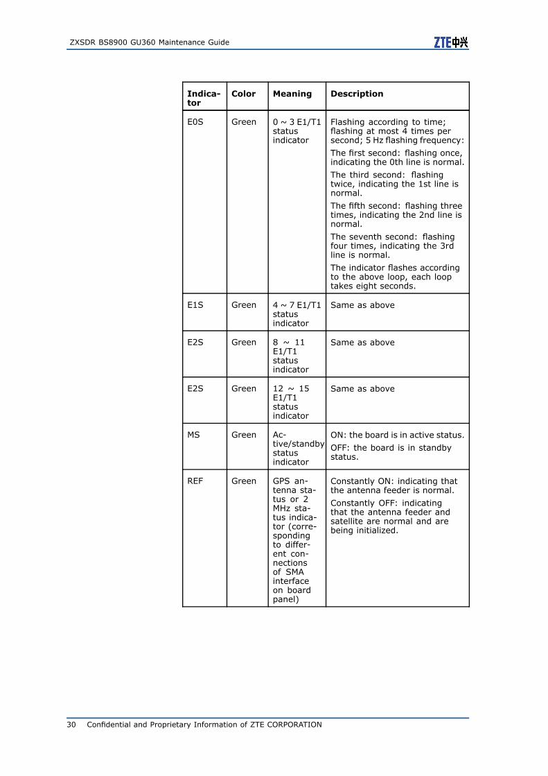
2. Table 6 lists normal status of indicators on CC panel.
TABLE 6 NORMAL STATUS OF CC PANEL INDICATORS
Indica-tor
Color Meaning Description
HS Blue Boardextractionindicator
ON: indicating that the boardcan be pulled out.
Flashing: indicating the board isbeing activated or deactivated.
OFF: indicating that the boardcan not be pulled out.
RUN Green Runningindicator
Constantly ON: the board isbeing reset.
Flashing at 1 Hz: the board isrunning in normal status.
Confidential and Proprietary Information of ZTE CORPORATION 29
ZXSDR BS8900 GU360 Maintenance Guide
Indica-tor
Color Meaning Description
E0S Green 0 ~ 3 E1/T1statusindicator
Flashing according to time;flashing at most 4 times persecond; 5 Hz flashing frequency:
The first second: flashing once,indicating the 0th line is normal.
The third second: flashingtwice, indicating the 1st line isnormal.
The fifth second: flashing threetimes, indicating the 2nd line isnormal.
The seventh second: flashingfour times, indicating the 3rdline is normal.
The indicator flashes accordingto the above loop, each looptakes eight seconds.
E1S Green 4 ~ 7 E1/T1statusindicator
Same as above
E2S Green 8 ~ 11E1/T1statusindicator
Same as above
E2S Green 12 ~ 15E1/T1statusindicator
Same as above
MS Green Ac-tive/standbystatusindicator
ON: the board is in active status.
OFF: the board is in standbystatus.
REF Green GPS an-tenna sta-tus or 2MHz sta-tus indica-tor (corre-spondingto differ-ent con-nectionsof SMAinterfaceon boardpanel)
Constantly ON: indicating thatthe antenna feeder is normal.
Constantly OFF: indicatingthat the antenna feeder andsatellite are normal and arebeing initialized.
30 Confidential and Proprietary Information of ZTE CORPORATION

Chapter 2 Routine Maintenance
Indica-tor
Color Meaning Description
ETH0 Green Abis/Iubinterfacelink statusindicator
Constantly ON: the Abis/Iubnetwork/electrical/opticalinterface physical links arenormal.
ETH1 Green ETH1networkinterfacelink statusindicator
ON: the network interfacephysical link is normal.
3. Table 7 lists normal status of indicators on UBPG (or BPC)panel.
TABLE 7 NORMAL STATUS OF UBPG (OR BPC) PANEL INDICATORS
Indica-tor
Color Meaning Description
HS Blue Boardextractionindicator
ON: indicating that the boardcan be pulled out.
Flashing: indicating the board isbeing activated or deactivated.
OFF: indicating that the boardcan not be pulled out.
RUN Green Runningindicator
Constantly ON: the board isbeing reset.
Flashing at 1 Hz: the board isrunning in normal status.
4. Table 8 lists normal status of indicators on FS panel.
TABLE 8 NORMAL STATUS OF FS PANEL INDICATORS
Indica-tor
Color Meaning Description
HS Blue Boardextractionindicator
ON: indicating that the boardcan be pulled out.
Flashing: indicating the board isbeing activated or deactivated.
OFF: indicating that the boardcan not be pulled out.
RUN Green Runningindicator
Constantly ON: the board isbeing reset.
Flashing at 1 Hz: the board isrunning in normal status.
MS Green Ac-tive/standbystatusindicator
ON: the board is in active status.
OFF: the board is in standbystatus.
Confidential and Proprietary Information of ZTE CORPORATION 31

ZXSDR BS8900 GU360 Maintenance Guide
5. Table 9 lists normal status of indicators on SA panel.
TABLE 9 NORMAL STATUS OF SA PANEL INDICATORS
Indica-tor
Color Meaning Description
HS Blue Boardextractionindicator
ON: indicating that the boardcan be pulled out.
Flashing: indicating the board isbeing activated or deactivated.
OFF: indicating that the boardcan not be pulled out.
RUN Green Runningindicator
Constantly ON: the board isbeing reset.
Flashing at 1 Hz: the board isrunning in normal status.
AbnormalityHandling
1. Table 10 lists abnormal status of indicators on RU60 (orRU40/RU02) panel.
TABLE 10 ABNORMAL STATUS OF RU PANEL INDICATORS
Indica-tor
Color Meaning Description
RUN Green Runningindicator
OFF: indicating self-test failure.
ALM Red Alarmindicator
Flashing at 5 Hz: indicatingcritical or emergent alarm.
Flashing at 1 Hz: indicatingminor alarm.
LINK Green Opticalinterfacelinkindicator
OFF: the fiber is disconnected.
RF Orange RF workingstatusindicator
OFF: RF has no output.
2. Table 11 lists abnormal status of indicators on CC panel.
TABLE 11 ABNORMAL STATUS OF CC PANEL INDICATORS
Indica-tor
Color Meaning Description
RUN Green Runningindicator
OFF: indicating self-test failure.
ALM Red Alarmindicator
ON: indicating that the boardhas alarm.
32 Confidential and Proprietary Information of ZTE CORPORATION

Chapter 2 Routine Maintenance
Indica-tor
Color Meaning Description
REF Green GPS an-tenna sta-tus or 2MHz sta-tus indica-tor (corre-spondingto differ-ent con-nectionsof SMAinterfaceon boardpanel)
Flashing at 1 Hz: indicatingthat the antenna feeder isdisconnected.
Flashing at 2 Hz: the antennafeeder is normal but can notreceive the satellite signal.
Flashing at 0.5 Hz: the antennais short-circuited.
Flashing at 5 Hz: no message isreceived at initialization.
ETH0 Green Abis/Iubinterfacelink statusindicator
OFF: the Abis/Iub networkinterface physical link isdisconnected.
ETH1 Green ETH1networkinterfacelink statusindicator
OFF: The network interfacephysical link is disconnected.
3. Table 12 lists abnormal status of indicators on UBPG (or BPC)panel.
TABLE 12 ABNORMAL STATUS OF UBPG (OR BPC) PANEL INDICATORS
Indica-tor
Color Meaning Description
ALM Red Alarmindicator
ON: the board has alarm.
RUN Green Runningindicator
OFF: indicating self-test failure.
4. Table 13 lists abnormal status of indicators on FS panel.
TABLE 13 ABNORMAL STATUS OF FS PANEL INDICATORS
Indica-tor
Color Meaning Description
ALM Red Alarmindicator
ON: the board has alarm.
RUN Green Runningindicator
OFF: indicating self-test failure.
5. Table 14 lists abnormal status of indicators on SA panel.
Confidential and Proprietary Information of ZTE CORPORATION 33

ZXSDR BS8900 GU360 Maintenance Guide
TABLE 14 ABNORMAL STATUS OF SA PANEL INDICATORS
Indica-tor
Color Meaning Description
ALM Red Alarmindicator
ON: the board has alarm.
RUN Green Runningindicator
OFF: indicating self-test failure.
Precautions None
Heat Exchanger Maintenance
Prerequisites Quarterly heat exchanger maintenance includes testing heatexchanger, replacing heat box, and cleaning heat exchangercavity.
Tools: cotton thread, cross screwdriver
Steps 1. Test the heat exchanger: Press the TEST key, the internal cir-culating fan, the external circulating fan, and the heater willbe forced to run for 2 minutes, and then automatically resumeto status before the test is performed. Under the test status,press the TEST key to exit the test.
2. Clean the heat box: Dust might accumulate in the heat boxafter long term usage or after serious sandstorm, which mightinfluence the heat exchanging effect. Replace the heat box tokeep the heat exchanger clean.
i. Automatic dust cleaning
If the external circulating fan stops running for 60 minutes,then after the 60 minutes, it will automatically run in fullrate for 3 minutes to clean dust on the heat box. In lowtemperature, this function is disabled when the heater isstarted.
ii. Manual dust cleaning
Press the CLEAN key to make the external circulating fanrun in full rate for 3 minutes, the fan then automaticallyresumes to status before dust is cleaned. Under the dust-cleaning status, press the CLEAN key to resume to statusbefore the dust is cleaned.
3. Clean the heat exchanger cavity.
i. Disconnect the heat exchanger’s power supply. Pull out the–48 V DC connector, 220 V AC connector, and DB9 connec-tor that are connected with the heat exchanger.
ii. Use screwdriver to disassemble cross screws on the coverplate and remove the cover plate.
iii. Use clean cotton thread to clean the inside of heat ex-changer cavity and the fan’s blade.
iv. Clean the heat box gently with clean cotton thread.
v. Clean the waterspout at the bottom of heat exchanger.
34 Confidential and Proprietary Information of ZTE CORPORATION
Chapter 2 Routine Maintenance
vi. Install the cover plate after cleaning is completed, and fas-ten screws.
Normal Result The five alarm indicators on the heat exchanger are green or green(flashing), indicating that the working status is normal.
AbnormalityHandling
If the indicator of a part is red, it indicates that the part isfaulty. For handling details, refer to Analysis and Handling ofHeat Exchanger Faults.
If the heat exchanger does not perform automatic dust clean-ing within specified time, or the heat exchanger has no re-sponse after the CLEAN key is pressed, perform troubleshoot-ing according to operation details described in Analysis andHandling of Heat Exchanger Faults.
Precautions In low temperature, when the heater is started, do not use themanual dust cleaning function randomly, because it might influ-ence the heating effect on internal equipments.
Cable Connection Checking
Checking RF Cable Connection
Prerequisites None
Steps 1. Check RF cable connectors to see whether they are tight, reli-able, and waterproof.
2. Check whether the RF cable is not damaged.3. Check whether the RF cable label is clear.
ReferenceStandard
1. The RF cable connection is reliable and waterproof.2. The RF cable is in good condition.3. The RF cable label is clear.
AbnormalityHandling
If water infiltrates the RF cable, perform waterproof handling. If aRF cable is damaged, replace the RF cable; for operation details,refer to Replacing RF Jumper.
Precautions When performing waterproof handling or replacing the RF cable,turn off the RU’s power supply, and relevant services supported byRU will be interrupted.
Checking GPS Cable Connection
Prerequisites None
Steps 1. Check GPS cable connectors to see whether they are tight,reliable, and waterproof.
2. Check whether the GPS cable is not damaged.3. Check whether the GPS cable label is clear.
ReferenceStandard
1. The GPS cable connection is reliable and waterproof.2. The GPS cable is in good condition.3. The GPS cable label is clear.
Confidential and Proprietary Information of ZTE CORPORATION 35

ZXSDR BS8900 GU360 Maintenance Guide
AbnormalityHandling
If water infiltrates the GPS cable, perform waterproof handling.If a GPS cable is damaged, replace the GPS cable; for operationdetails, refer to Replacing GPS Jumper.
Precautions None
Semiyearly Maintenance
Biannual Routine Maintenance Items
Table 15 lists the biannual routine maintenance items.
TABLE 15 BIANNUAL ROUTINE MAINTENANCE ITEMS
Category Items
Equipment cleaning Cleaning fan subrack
Board diagnosis and test Board diagnosis and test
Equipment Cleaning
Cleaning Fan Subrack
Prerequisites 1. Tools: clean cotton gauze, antistatic soft brush or dust collec-tor.
2. Standby fan subrack.
Steps 1. Use clean cotton gauze, antistatic soft brush, or dust collectorto clean the fan and circuit board in the standby fan subrack.
2. Use the standby subrack to replace the running fan subrackin the cabinet. For operations details, refer to Replacing FanSubrack.
3. Clean the replaced fan subrack as described in step 1, and thecleaned fan subrack can be used as standby fan subrack.
4. Replace all other running fan subracks in the cabinet and cleanthem as described above.
ReferenceStandard
The fan subrack is clean.
AbnormalityHandling
None
Precautions The process of replacing fan subrack can not exceed 5 minutes.
36 Confidential and Proprietary Information of ZTE CORPORATION

Chapter 2 Routine Maintenance
Board Diagnosis and Test
Prerequisites Communication between the NetNumen M31 client and theNetNumen M31 server is normal.
Connections between the NetNumen M31 server and networkelements are normal.
Steps 1. Log in to the NetNumen M31 client.2. Start the NE agent.3. In Physical View of the Topology Management tab, click
NE Management > Test Management, as shown in Figure17.
FIGURE 17 ENTERING TEST MANAGEMENT
4. In the left equipment view of Test Management, find theBS8900 node.
5. Select the board in BS8900 GU360 to be diagnosed and per-form the test.
ReferenceStandard
After the test is completed, the board color is yellow/green. Clickthe board and the test result is displayed.
The test result is normal.
Confidential and Proprietary Information of ZTE CORPORATION 37

ZXSDR BS8900 GU360 Maintenance Guide
AbnormalityHandling
Analyze the fault cause according to the test result.
Precautions Before using Test Management, the NE agent must be startedfirst.
Yearly MaintenanceYearly Routine Maintenance Items
Table 16 lists the yearly routine maintenance items.
TABLE 16 YEARLY ROUTINE MAINTENANCE ITEMS
Category Items
Measuring power amplifier’s out-put power
Base station testMeasuring Standing Wave Ratio(SWR)
Board changeover test Testing CC board changeover
Checking lightning protector
Checking grounding cableGrounding lightning protectioncheck Testing grounding resistance
Checking antenna feeder interface
Checking tightness of antenna andtower amplifier
Checking directional antennadowntilt
Antenna feeder system check
Checking waterproof conditionsfor antenna feeder connector andlightning protective grounding clip
Checking iron tower (optional)
Checking pole (optional)
Other checks
Checking running status of bat-teries
38 Confidential and Proprietary Information of ZTE CORPORATION

Chapter 2 Routine Maintenance
BTS Testing
Measuring Power Amplifier’s Output Power
Prerequisites Tools:
1. One 3 1/2 digital multimeter2. One 150 W thru-line wattmeter3. RF cables4. Other metal fittings
Steps 1. Turn off the Radio Unit (RU)’s power supply. The RU’s powerswitch is on the front panel of PDM.
2. Disconnect the power supply and make the RU not outputpower, loosen the antenna feeder cable connectors, and con-nect them with a thru-line wattmeter and a large-power load.
Note:
When the RU is not connected with any antenna, connect it witha 100 Wmicrowave power load. When the RU is connected withantenna, it needs not be connected with any load.
3. Turn on the power supply and add excitation (RU has output).Read the power of the set frequency band (GSM900: 925 MHz~ 960 MHz; GSM1800: 1805 MHz ~ 1880 MHz). In the caseof full power, read the output power and the gain flatness.
4. After the test is completed, disassemble connections amongthru-line wattmeter, large-power load, and the Power Amplifier(PA) output end, restore the connection between PA output endand the antenna feeder cable. Make the RU power on again.
ReferenceStandard
RU60: for GMSK, the maximum cabinet-top output power is47.8 dBm (60 W); for 8PSK, the maximum cabinet-top outputpower is 46.0 dBm (40 W).
RU02: for GMSK, the maximum cabinet-top output power is46.0 dBm (40 W); for 8PSK, the maximum cabinet-top outputpower is 43.5 dBm (22.5 W).
AbnormalityHandling
If the test result is abnormal, check whether power control param-eters at background are set correctly, and check whether RF cableconnections between modules and antenna feeders are reliable.
Common PA faults include PA module (front-end) faults and PAtube (rear-end) faults. They cause low gain and decreased outputpower. If PA is faulty, replace the RU where the faulty PA is located.
Precautions During the measuring process, services supported by the RUshould be interrupted.
Confidential and Proprietary Information of ZTE CORPORATION 39

ZXSDR BS8900 GU360 Maintenance Guide
Measuring SWR
Prerequisites Site Master
50 Ω SMA (M) matching load
SMA torque spanner
Allen screwdriver
One N(M) -N(M) testing cable
Steps 1. Turn on the power switch of Site Master2. Select OPT in the main menu.3. Select the item to be measured: SWR.4. Select the FREQ key in the main menu, and enter start and
stop scanning frequencies.5. Select the START CAL key to calibrate the measuring instru-
ment as follows:
i. Connect the circuit breaker (OPEN) with TEST PORT, andselect ENTER.
ii. Connect the short-circuit device (SHORT) with TEST PORTand select ENTER.
iii. Connect the 50 Ω load with TEST PORT and select ENTER,the system performs calibration automatically.
6. In SCALE of the main menu, enter the values of TOP, BOTTOM,and LIMIT. To facilitate query, it is recommended to set thevalue of TOP to be 1.5 and BOTTOM to be 1.0.
7. In the FREQ menu, select the MARKER key, and then selectEDIT to edit MARKER to make it show the Standing WaveRatio (SWR) value.
8. Read the values. Examine whether these values meet the re-quirements and then save them.
9. Reconnect connectors of the equipment and restore the sys-tem.
ReferenceStandard
Normal test result: SWR < 1.5
AbnormalityHandling
If the test result is abnormal, use the fault location function (DTF)to find the fault position and fault cause, and perform troubleshoot-ing.
Precautions 1. Each time before power-on for measurement, calibrate themeasuring instrument.
2. If the measurement is conducted during equipment running, itis necessary to notify the customer. Lock relevant sectors orget the customer’s approval, then turn off relevant equipmentpower supply and perform the test. Usually, it is not recom-mended to perform the measurement in this way.
3. During the measurement, observe the equipment’s runningstatus with care.
Testing CC Board Changeover
Prerequisites Communication between the NetNumen M31 client and theNetNumen M31 server is normal.
40 Confidential and Proprietary Information of ZTE CORPORATION

Chapter 2 Routine Maintenance
Connections between the NetNumen M31 server and networkelements are normal.
Steps 1. Log in to the NetNumen M31 client.2. Start the NE agent.3. In Physical View of the Topology Management tab, click
NE Management > Configuration Management, as shownin Figure 18.
FIGURE 18 ENTERING CONFIGURATION MANAGEMENT
4. In the left equipment view of Configuration Management,find the BS8900 node, double-click it to open the rack view.
5. Right-click on the CC board in BS8900 GU360 to perform ac-tive-standby changeover.
ReferenceStandard
The board changeover is normal. Perform the dialing test after theboard changeover, and all services are normal.
AbnormalityHandling
None
Confidential and Proprietary Information of ZTE CORPORATION 41

ZXSDR BS8900 GU360 Maintenance Guide
Precautions None
Grounding Checking
Checking Lightning Protector
Prerequisites 1. Site Master2. 50 Ω N(F) matching load3. One testing cable4. Adapters N(M)-7/16DIN(M), N(M)-7/16DIN(F)
Steps The following takes the 1/4λ lightning protector for example toexplain the method of examining whether a lightning protector isnormal.
1. Turn off the BS8900 GU360 power supply.2. Loosen the jumper connectors connected to both ends of the
lightning protector.3. Select the START CAL key to calibrate the measuring instru-
ment as follows:
i. Connect the circuit breaker (OPEN) with TEST PORT, andselect ENTER.
ii. Connect the short-circuit device (SHORT) with TEST PORTand select ENTER.
iii. Connect the 50 Ω load with TEST PORT and select ENTER,the system performs calibration automatically.
4. Connect the Site Master to a port on the lightning protector viatesting cable.
5. Connect the other port on the lightning protector with thematching load.
6. Read the Site Master and examine whether the lightning pro-tector’s return loss is within the normal range.
7. Repeat Step 4 through 6 to measure the return loss of the otherport on the lightning protector.
8. Adjust the multimeter to ×10 K to measure the resistance ofconductors in the high-frequency sockets at both ends of thelightning protector.
9. Adjust the multimeter to ×1 to measure the resistance be-tween the conductor in the antenna and the ground.
10. If the test result is normal, connect jumper connectors to thetwo ports on the lightning protector. Power-on the BS8900GU360 to restore the system.
ReferenceStandard
Technical indices of the lightning protector satisfy the productspecifications. The normal test result is larger than 20 dB.
The resistance of conductors in the high-frequency sockets at bothends of the lightning protector is larger than 20 MΩ.
The resistance between the conductor in the antenna and theground is approximately 0 Ω.
AbnormalityHandling
If the test result is abnormal, it is advised to replace the lightningprotector.
42 Confidential and Proprietary Information of ZTE CORPORATION
Chapter 2 Routine Maintenance
Precautions Take care of the grounding connection of the lightning protectorso that they may not be damaged.
Checking Grounding Cable
Prerequisites None
Steps Check each grounding cable to see whether its connectors areloose, rusty or aging.
ReferenceStandard
No connector is loose, rusty or aging.
AbnormalityHandling
Replace the grounding cables and reconnect them.
Testing Grounding Resistance
Prerequisites Prepare the earth resistance tester (model ZC-8) before testingthe grounding resistance.
Steps 1. Disconnect the grounding down-lead from the equipment, andconnect it to the earth resistance tester.
2. Mount two auxiliary piles 20 m and 40 m away from the testingpoint (local voltage/remote current). To ensure good contactbetween the piles and the earth, sprinkle water around them.
3. Connect the two auxiliary piles and the earth resistance tester’sterminals through conducting wire. Shake the handle of thetester to measure the grounding resistance. If the earth re-sistance tester gets power supply from battery, the groundingresistance can be read directly by pressing the button.
ReferenceStandard
Grounding resistance ≤ 5 Ω. In area where the number of thun-derstorm days per year is less than 20, the grounding resistancecan be less than 10 Ω. Measure the grounding resistance accord-ing to the design requirement if there is any.
AbnormalityHandling
1. Check whether the connection between the grounding down-lead and the grounding net is reliable.
2. Check whether the grounding net system satisfies the designrequirement and whether the resistance-reducing agent isadded periodically.
Antenna Feeder System Checking
Checking Antenna Feeder Interface
Prerequisites None
Steps 1. Observe indicators on the backplane to see whether there isany SWR alarm.
2. Check whether the RF cables of the antenna feeder system areaging.
ReferenceStandard
1. Indicators on the backplane show no SWR alarm.2. The RF cables of the antenna feeder system are not aging.
Confidential and Proprietary Information of ZTE CORPORATION 43

ZXSDR BS8900 GU360 Maintenance Guide
AbnormalityHandling
1. According to the SWR measuring method described in Measur-ing SWR, check SWR of the jumpers, main feeders and anten-nas. Check segment by segment from the combiner’s outputport to locate the faulty parts. Replace the faulty parts untilthe fault is removed.
2. If the RF cables are aging, replace them.
Checking Firmness of Antenna and TowerAmplifier
Prerequisites Prepare the spanner before checking the firmness of antenna andtower amplifier.
Steps 1. Check whether the fixing clips of antennas and antenna sup-ports are reliable.
2. Check whether the fixing clips of the tower amplifier are reli-able.
ReferenceStandard
The fixing clips of antennas and tower amplifiers are reliable, with-out shaking or sliding.
AbnormalityHandling
Use the spanner to tighten the fastening screws.
Checking Directional Antenna Tilt
Prerequisites Prepare the angle gauge before checking a directional antenna’stilt.
Steps Use the rotary angle gauge with a bubble tube to check the tiltof a directional antenna, as shown in Figure 19. If using otherinstrument, refer to the corresponding instrument’s instructions.
FIGURE 19 ANGLE GAUGE
1. Press the angle gauge against the object to be measured, asshown in Figure 20.
44 Confidential and Proprietary Information of ZTE CORPORATION

Chapter 2 Routine Maintenance
FIGURE 20 MEASURING OBJECT WITH ANGLE GAUGE (1)
2. Rotate the dial until the bubble in the tube is located in themiddle of the two indication rings.
3. Read the scale on the dial.
ReferenceStandard
The tilt is consistent with that specified in network planning.
AbnormalityHandling
1. Rotate the dial to the set angle.2. Press the object to be measured against the dial chassis firmly.
Move the object and chassis together until the bubble in thetube moves to the middle of the two indication rings, as shownin Figure 21.
FIGURE 21 MEASURING OBJECT WITH ANGLE GAUGE (2)
Confidential and Proprietary Information of ZTE CORPORATION 45

ZXSDR BS8900 GU360 Maintenance Guide
Checking Waterproof Status of Antenna FeederConnectors and Lightning Protection GroundingClips
Prerequisites Prepare the following materials before checking the waterproofstatus of antenna feeder connectors and lightning protectiongrounding clips:
Waterproof adhesive
Sealant
Insulating tape
Steps Check whether water leakage or cracks exist on antenna feederconnectors and lightning protection grounding clips.
ReferenceStandard
No water leakage or cracks exist on antenna feeder connectorsand lightening protection grounding clips.
AbnormalityHandling
Perform the following steps to make waterproof treatment:
1. Turn off the power supply of BS8900 GU360.2. Disassemble the existing waterproof materials.3. Wrap the waterproof adhesive at the connector, apply the
sealant, and then wrap the insulating tape. Wrap the tapelayer by layer from bottom to top to avoid rainwater leakage.
4. Make the BS8900 GU360 power on.
Other Checking
Checking Iron Tower
Prerequisites None
Steps Check tower lamps, tower structure distortion, and tower basesinking.
Measure the verticality and height of the iron tower.
Check the degree of tightness of structure bolts. Check thecorrosion-proof and rustproof conditions.
ReferenceStandard
The structure distortion, base sinking, and verticality of the irontower all satisfy the design requirements. The structure bolts arefixed tightly and there is no corrosion or rust on them.
AbnormalityHandling
Perform appropriate handling for abnormality if there is any.
Checking Pole
Prerequisites None
Steps Check the following items:
Installation of the pole fasteners.
46 Confidential and Proprietary Information of ZTE CORPORATION

Chapter 2 Routine Maintenance
Forces on devices including the pole, cables on the guyedtower, and ground anchors.
Corrosion-proof and rustproof conditions.
Pole verticality.
ReferenceStandard
The pole is vertical and tightly fixed, without any corrosion or rust.
AbnormalityHandling
Perform appropriate handling for abnormality if there is any.
Checking Running Status of Batteries
Prerequisites None
Steps Check whether the battery has leakage and whether connectioncables have reliable contact.
ReferenceStandard
There is no battery leakage and the connection is normal.
AbnormalityHandling
Refer to the battery instructions.
Precautions None
Confidential and Proprietary Information of ZTE CORPORATION 47
ZXSDR BS8900 GU360 Maintenance Guide
This page is intentionally blank.
48 Confidential and Proprietary Information of ZTE CORPORATION

C h a p t e r 3
Emergency Maintenance
Table of ContentsOverview..........................................................................49Emergency Process............................................................53Service Recover ................................................................56
OverviewEmergency Maintenance Scenarios
Table 17 lists the application scenarios of BS8900 GU360 emer-gency maintenance.
TABLE 17 FAULT SYMPTOM AND DETAILS
Fault Symptom Fault Details
The service is interrupted at a fewBS8900 GU360.
The service is interrupted at afew BS8900 GU360, all mobilesubscribers in correspondingcoverage areas encountercommunication break or can notaccess the network normally.
The service is interrupted at alarge amount of BS8900 GU360.
The service is interrupted at alarge amount of BS8900 GU360that are mutually associated, a lotof mobile subscribers encountercommunication break or can notaccess the network normally.
Emergency Maintenance Flow
Figure 22 shows the flow of emergency maintenance.
Confidential and Proprietary Information of ZTE CORPORATION 49

ZXSDR BS8900 GU360 Maintenance Guide
FIGURE 22 EMERGENCY MAINTENANCE FLOW
The emergency maintenance flow include the following steps:
Check Service According to the emergency fault symptom, and through the topol-ogy at Network Management System (NMS) client and reportedalarms, decide whether the fault is caused by site problems andwhether the fault exists in a few sites or a large amount of sites.
Recordabnormality and
locate fault
According to the emergency maintenance flow given in Figure 22,locate the fault and make records in the abnormality record formas shown in Table 1.
TABLE 1 ABNORMALITY RECORD FORM
Record Item Abnormality Details
Emergency fault occurrence time
Emergency fault occurrence range
50 Confidential and Proprietary Information of ZTE CORPORATION

Chapter 3 Emergency Maintenance
Record Item Abnormality Details
Critical alarm reported
Abnormal performance index
Board with abnormal indicator
Site version number
NMS version number
Operation log information
Status query information
Signaling tracing information
Note:
In case of any emergency fault occurring, record the fault detailsas much as possible to facilitate fault locating.
Analyze fault Perform fault analysis and troubleshooting according to the posi-tion located in previous fault locating.
If the fault is not due to BSS problems, contact relevant mainte-nance personnel to solve the problem.
If the fault is due to BSS problems, perform analysis to decidewhether the fault cause is at BSC or base station, and implementcorresponding handling.
Emergency help If on–site maintenance personnel can not remove the fault, con-tact ZTE Corporation.
Resume service After the fault is located, resume the service as soon as possible.If the fault can not be located immediately, try methods such asboard changeover, resetting board, or replacing board, to resumethe service in time.
Caution:
Before resuming service, maintenance personnel should performsystem data backup. If it is necessary to change hardware config-uration, such as cable connection or board’s slot position, recordthe current condition first.
The procedure of resuming service must be recorded.
Observe resumedservice
Perform the dialing test and performance report statistics, and col-lect subscribers’ complaints, to learn details of service resumption.
After the service is resumed through emergency maintenance,make sure that the system is running normally. Arrange personnelto attend during service peak hours to ensure that problems canbe solved in time if there is any.
Confidential and Proprietary Information of ZTE CORPORATION 51

ZXSDR BS8900 GU360 Maintenance Guide
Epilogue Summarize the emergency maintenance experience and fill in theemergency troubleshooting record form, and give feedback of thetroubleshooting result to the customer and ZTE Corporation.
Emergency Maintenance Precautions
Precautions The following items should be noticed in the emergency mainte-nance:
Usually, the emergency maintenance has great influence onthe system running. Consequently, it is required that mainte-nance personnel must be familiar with the equipment. Mainte-nance personnel should have certain maintenance experienceor perform the maintenance under the guidance of experiencedmaintenance personnel.
If the fault greatly influences the system running, contact ZTECorporation as soon as possible no matter whether the main-tenance personnel could remove the fault.
Before the emergency maintenance is performed, implementdata backup for the site first.
MaintenanceGuide
Before performing emergency maintenance for BS8900 GU360,the following basic principles of emergency maintenance shouldbe fully considered and followed:
1. The purpose of emergency maintenance is to rapidly resumethe system service. Consequently, the maintenance personnelshould study and grasp the emergency maintenance materialof BS8900 GU360 and related equipments.
2. Maintenance personnel should keep calm in case of any emer-gency service interruption occurring at BS8900 GU360. Con-tact NMS maintenance personnel first, query relevant alarmsat NMS to locate the site where the service interruption occurs.
If the service interruption occurs at a large amount ofBS8900 GU360, check BSCs to which the Abis interface ofthese sites are connected and transmission circuits to seewhether there is any abnormality, such as faulty moduleof faulty board, data modification, or version changes. Ifthe BSC, transmission equipment, and transmission circuithave no problem, then maintenance personnel can go todifferent sites to perform maintenance. NMS maintenancepersonnel should cooperate with the site maintenancepersonnel.
If the service interruption is due to problems at a single site,contact NMS maintenance personnel first to obtain alarminformation of the faulty site to locate the fault range. Taketools and spare parts of the base station to the faulty siteto perform emergency maintenance.
3. After the emergency maintenance is completed, collect equip-ment alarm information related to the fault in time. Send rel-evant troubleshooting report, equipment alarm file, and logfile to ZTE Corporation for further analysis, which helps betterZTE’s after-sale service.
52 Confidential and Proprietary Information of ZTE CORPORATION

Chapter 3 Emergency Maintenance
Emergency ProcessAutomatic Active-StandbyChangeover
Redundant backup is adopted in the clock, IQ switching, and trans-mission of BS8900 GU360. If no problem exists in redundantboards:
When one of the control clock modules of BS8900 GU360 be-comes faulty, the system automatically performs cold switch-ing, and the service will be interrupted for about 10 seconds.
When one of the FS network switching module becomes faulty,it only influences the running of the RU connected with it. Forring networking, the system automatically performs switchingto another FS IQ, and the service will be interrupted for about10 seconds.
Manual Active-Standby Changeover
Context The manual active-standby changeover is performed when faultoccurs at the transmission or the clock. The changeover time iswithin 30 seconds.
Steps 1. Log in the local or centralized NMS.
2. Right-click on the main CC board to initiate the active-standbychangeover.
Figure 23 shows the operation in the centralized NMS.
Confidential and Proprietary Information of ZTE CORPORATION 53

ZXSDR BS8900 GU360 Maintenance Guide
FIGURE 23 OMM ACTIVE-STANDBY CHANGEOVER
Note:
If only one board is configured, then the changeover menu willnot be displayed. If two boards are configured, and one boardis in active status while the other board is in standby status,then the changeover menu will be displayed.
END OF STEPS
Resetting Power-Down Board
Context Perform power-down resetting for the faulty board.
Steps 1. Log in the local or centralized NMS.
2. Right-click on the faulty board to initiate the power-down re-setting.
Figure 24 shows the operation in the centralized NMS.
54 Confidential and Proprietary Information of ZTE CORPORATION

Chapter 3 Emergency Maintenance
FIGURE 24 OMM POWER-DOWN RESETTING
END OF STEPS
Checking Whether Fan Is RunningNormally
Context Check whether the fan is running normally.
Steps 1. Log in the local NMS.
2. Right-click on the SA/SE, RTR/DTR/FCE board to initiate theenvironment information query.
3. Check whether the temperature is within the nromal range.Usually, the temperature should be lower than 55.
END OF STEPS
Confidential and Proprietary Information of ZTE CORPORATION 55

ZXSDR BS8900 GU360 Maintenance Guide
Service RecoverService Resuming Flow
The flow of resuming service is shown in Figure 25.
56 Confidential and Proprietary Information of ZTE CORPORATION

Chapter 3 Emergency Maintenance
FIGURE 25 SERVICE RESUMING FLOW
Confidential and Proprietary Information of ZTE CORPORATION 57

ZXSDR BS8900 GU360 Maintenance Guide
Service Recover Procedure
Checking Whether PM Is Normal
Context Check the PM’s power supply to see whether the cabinet has nor-mal power supply.
Steps 1. On the rack panel, check whether the RUN indicator of PM isgreen, which indicates normal status.
2. If the indicator is abnormal, check the PM board.
END OF STEPS
Repairing Power Supply System
Context Usually, abnormal power supply of the cabinet is caused by faultin the power supply system of the equipment room. Perform thefollowing steps to solve the problem.
Steps 1. To avoid accidents, before the equipment room’s power supplysystem becomes normal, turn off all power switches on thepanel of the power distribution shelf of the cabinet.
2. Repair the power supply system as soon as possible.
END OF STEPS
Checking Power Supply of Main Boards
Context After the cabinet’s power supply becomes normal, check whetherthe main service shelf’s power supply is normal.
Steps 1. On the rack panel, check the RUN indicator of CC to seewhether it is ON, which indicates normal running.
2. On the rack panel, check the RUN indicator of SA/SE to seewhether it is ON, which indicates normal running.
3. If the main service shelf’s power supply is abnormal, i.e. theRUN indicator is OFF, then before finally finding out the faultcause, it is recommended not to perform any operation, in-stead, maintenance personnel should contact ZTE Corporationimmediately to get technical support.
END OF STEPS
Checking Whether Service Boards Run Normally
Context After the cabinet’s power supply becomes normal, check whetherthe power supply of service boards is normal.
58 Confidential and Proprietary Information of ZTE CORPORATION

Chapter 3 Emergency Maintenance
Steps 1. On the rack panel, check the RUN indicator of FS to seewhether it is ON, which indicates normal running.
2. On the rack panel, check the RUN indicator of BPC to seewhether it is ON, which indicates normal running.
3. On the rack panel, check the RUN indicator of UBPG to seewhether it is ON, which indicates normal running.
4. Check whether corresponding boards are configured inOMM/LMT.
5. If a board has been configured in OMM/LMT but its RUN indi-cator is OFF, then unplug and plug this board.
6. If the problem persists, replace the board.
END OF STEPS
Resetting/Replacing Board
Context If a board fails, reset it or replace it.
Steps 1. Check whether the RUN indicator of the board is abnormal. Ifthe board is abnormal, the RUN indicator is not green and theAlarm indicator flashes periodically.
2. Log in OMM/LMT to check the current alarms.
3. Perform troubleshooting according to the alarm information.
END OF STEPS
Checking Whether Fault Is due to ConfigurationData Modification
Context If the configuration data is inappropriate or the system patch isloaded incorrectly, then reloading such data and program willcause board fault or system fault.
Steps Perform analysis and comparison of configuration data through theLMT/OMM operation log.
END OF STEPS
Resuming Original Configuration Data
Context If the equipment fault is due to inappropriate configuration data,then resume the original configuration data.
Steps 1. Extract the backup data which is prepared before the operationis performed.
2. Resume the original configuration data.
Confidential and Proprietary Information of ZTE CORPORATION 59

ZXSDR BS8900 GU360 Maintenance Guide
3. Maintenance personnel can also resume correct configurationdata under the guidance of ZTE technical personnel.
END OF STEPS
Collecting Fault Information
Context Maintenance personnel should collect fault information in time nomatter whether the fault is removed or not. This facilitates furtherfault analysis and locating.
Steps 1. Export the operation log of the current site through LMT.
2. Export current alarms and history alarms of the current site.
3. Export the service failure statistics information of the currentsite through LMT.
4. Export all information under the directory Log of CC-1 andCC-2 of the current site, as shown in Figure 26.
FIGURE 26 EXPORTING FOREGROUND LOG INFORMATION
Note:
Log in the foreground through ftp, both the user name and thepassword are null, ftp>cd /ROOT/log
Extract files under the directory Log to the local machine.
5. Export the abnormal probe information of the current site.
END OF STEPS
60 Confidential and Proprietary Information of ZTE CORPORATION

C h a p t e r 4
Troubleshooting
Table of ContentsCommon Troubleshooting Process ........................................61Common Service Troubleshooting ........................................63Common Equipment Troubleshooting....................................66
Common TroubleshootingProcessUsually, the troubleshooting process includes the following fourstages:
Collecting fault information
Analyzing fault causes
Locating fault
Removing fault
Collecting FaultInformation
The following lists sources of fault information collection:
Subscribers’ complaints;
Abnormality detected in daily maintenance;
Alarms and notifications reported at NMS client;
Boards’ indicator status.
Maintenance personnel should collect relevant original informationfrom various sources as much as possible.
Analyzing FaultCauses
After the fault information is obtained, maintenance personnel per-form analysis to decide the probability of each fault cause, whichis taken into account in the sequence of troubleshooting.
Locating Fault After the fault cause analysis is completed, maintenance personneluse various troubleshooting methods to exclude impossible faultcauses and decide the real fault causes. The following lists somecommon methods for fault analysis and locating:
Viewing alarms and operation log
Alarms and operation log viewing is performed through alarmmanagement and operation log view interfaces in BSS opera-tion and maintenance system.
Confidential and Proprietary Information of ZTE CORPORATION 61
ZXSDR BS8900 GU360 Maintenance Guide
The alarm management interface allows viewing and analyz-ing current alarms, history alarms and common notificationsreported by the Network Element (NE). This ensures detect-ing network operation abnormalities in time, locating, isolatingand troubleshooting the fault as early as possible
The operation log in user management allows tracing systemparameter modifications, locating relevant terminals and op-erators, and detecting faults caused by improper operations.
Indicator status analysis
Analyzing indicator status helps in fault detection. Indicatorson the boards are observed to locate the fault position.
This method requires familiarity with status of all indicatorsand their respective meanings.
Performance analysis
This is done in the performance management interface of BSSoperation and maintenance system, through which the BSSperformance management and signaling tracing can be imple-mented.
Through the performance management interface, users cancreate performance measurement tasks, generate various per-formance reports, and understand various performance indicesof BSS. Through such information analysis, maintenance per-sonnel can learn the load distribution in the network and adjustnetwork parameters in time to improve network performance.
Through the signaling tracing interface, users can trace BSS-related signaling (including signaling at Gb interface). It facili-tates checking various signaling flows during the commission-ing and debugging process.
Using analysis tools
During BS8900 GU360 maintenance , the maintenance per-sonnel use testing mobile phone, signaling analyzer, bit erroranalyzer, and other instruments to analyze, locate and trou-bleshoot faults.
Plugging and unplugging
When a fault occurs in a board, loosen the fixing screws on thefront panel, unplug and plug the board and external connec-tors. This method helps ensure good contact or handle abnor-mal processor problems.
Pressing the cable connector after the system is powered offalso helps remove faults due to bad contact.
Comparison and interchange
The comparison method refers to comparing the possibly faultyboard with another normal board in similar condition in thesystem (such as another normal board in the same slot of adifferent module). Compare the running status, jumpers, andcable connections. It can be diagnosed through comparisonwhether the board is faulty.
The interchange method refers to replacing the possibly faultyboard with a spare board or another identical normally-run-ning board. If the fault disappears after replacement, then theboard is faulty.
62 Confidential and Proprietary Information of ZTE CORPORATION
Chapter 4 Troubleshooting
Note:
When performing fault analysis and fault locating, the oper-ation of plugging or unplugging board might be performed.Maintenance personnel should strictly follow relevant specifi-cations to perform such operations.
Isolation method
When a system component is faulty, relevant boards or shelfcan be separated to judge whether the fault is caused by mu-tual influence.
Self-test
This method refers to fault judgment through self-test afterthe system or board is powered-on again. Generally, duringthe power-on and self-test process, indicators flash accordingto certain rules, which can be used to diagnose whether theboard is faulty.
Contacting ZTE Corporation to get technical support
During the troubleshooting process, if maintenance personnelencounter difficult problems that can not be solved, they cancontact ZTE Corporation via telephone, fax, or e-mail to gettechnical support.
Removing Fault After a fault is located, maintenance personnel perform appropri-ate handling to remove the fault to resume normal system running.
Common ServiceTroubleshootingLow Call Completion Ratio
Fault Symptom Users complain that the call completion ratio (i.e. the ratio of thecalled party being connected) decreases significantly and calls can-not be connected at all in the worst cases.
Fault Analysis The call completion ratio is a basic index to evaluate overall per-formance of the system. There are a lot of factors that may affectit, including:
1. Boards and parts of the access–side equipments (including BTSand BSC) fail; or parts of the core–network–side equipments(such as MSC) fail. Hence, fewer resources are available andusers’ access requests are mostly rejected.
2. Software version mismatch exists among equipments or parts,which is caused by incorrect operations during system upgradeor version update. It influences normal running of the system,causing disorder in the interactive flow of important signaling
Confidential and Proprietary Information of ZTE CORPORATION 63

ZXSDR BS8900 GU360 Maintenance Guide
or messages. As a result, the user’s access becomes very dif-ficult.
3. Early-stage network planning or network construction is notcomplete or resource configuration is incorrect, causing inap-propriate allocation of system service resources. Resources insome areas are insufficient, especially areas with heavy traffic,which reduces the call completion ratio.
4. Electromagnetic interference, such as the pilot pollution, existsin the propagation environment, causing degradation of Signalto Noise Ratio (SNR), which reduces the call completion ratio
Troubleshooting 1. Set statistics tasks on the performance statistics interface atthe operation and maintenance background, measure the callcompletion ratio in the problem area, and compare the resultwith old statistic data.
2. If the statistics index does not decrease significantly, thenthere is a great probability that external electromagneticinterference exists.
Use a radio signaling analyzer to observe the radio signalingconnection process, and record characteristics of abnormal in-terruptions.
Use a spectrum analyzer to scan the frequency band in use todetect whether there is any external electromagnetic pollution.
Locate the interference source and try to eliminate it.
3. If the statistics index does decrease significantly, then checkequipment faults, resource configuration, and software ver-sions.
i. According to the problem area complained by users, de-termine whether the whole network, a BTS, or a sector isinfluenced.
ii. Query current alarms and history alarms. Check the work-ing status of equipment parts, transmission equipments,and clock source. Eliminate any fault found.
iii. Observe the utilization of relevant resources continuously,for example, the board’s CPU utilization, link load, cell traf-fic, and radio channel utilization. Adjust resource config-uration data and expand the equipment capacity if neces-sary.
iv. Check software/hardware versions of each equipment andpart to eliminate faults due to version mismatch.
4. If performance indices of the whole network degrade, it mightbe a sign that the system is to be down. Handle the problemimmediately, and report it to ZTE Corporation in time.
Poor Call Quality
Fault Symptom The following lists some common symptoms of poor call quality:
1. Call drop: Abnormal interruptions occur frequently during thecall process.
2. Unidirectional call: One party can not hear the other partyduring the call process.
64 Confidential and Proprietary Information of ZTE CORPORATION

Chapter 4 Troubleshooting
3. Intermittent voice: The voice is intermittent during the callprocess.
Fault Analysis 1. The mobile terminal has poor demodulation performance(receiving sensitivity), and fluctuation of the receiving fieldstrength affects the call quality.
2. Either party or both parties of the call are on the edge of cell(s)or the signal is blocked by landform or buildings, thus the signalfield strength is weak and fluctuates greatly. It results in a highframe error rate, affecting the voice quality.
3. Strong electromagnetic interference exists in the space, includ-ing pilot pollution, carrier interference, and abnormal sectorpower of adjacent BTS. It results in the decreased voice qual-ity.
i. Pilot pollution: When there are three or more pilot frequen-cies with nearly equal magnitude in the coverage area, sur-plus pilot frequencies become a strong interference source.
ii. Carrier interference: In the coverage area, if a frequencythat approximates the BTS’s carrier frequency exists,strong signal interference will be generated. The interfer-ence might be continuous or in a burst.
iii. The power of adjacent BTS’s sector being abnormal: Thepower output of the adjacent BTS’s sector often fluctuatesat an amplitude of over 3 dB, causing interference to cor-responding sectors of other BTS and overlapped soft–han-dover area of adjacent BTS.
4. The user is moving during the call process, when there areobstacles in the surrounding, the signal is blocked suddenly,air links undergo fast fading or the receiving signal strengthundergoes sudden change. Because the rapid power controlfunction can not efficiently take into effect, the continuity ofvoice quality is affected.
5. Resources occupied during the call process, such as carrier,link, board, switching network, and transmission equipment,have faults and do not work stably, affecting the stability ofthe call process.
6. Data configurations are incorrect or versions of hardwareand software do not match, affecting the stability of the callprocess.
Troubleshooting 1. Check the mobile terminal used in the call process. Use multi-ple terminals of different models for comparison if possible, todetermine whether the terminal has any problem.
2. Test the signal field strength in the conversation area to eval-uate the coverage effect. Optimize the network if the signalfield strength in the area is weak.
3. Use instruments to monitor whether there is any pilot pollutionor carrier interference in the area. If so, find out the interfer-ence source and perform appropriate handling.
4. At the operation and maintenance background, query the re-cent downlink power output status of all adjacent BTS. For anyabnormal power output detected, check the corresponding BTSand eliminate relevant fault.
5. If the voice quality degradation occurs only in the movingprocess, then it might be due to that the power control mech-anism can not adapt to the special geographical environmentwhere the call process is proceeded. In this case, networkoptimization should be performed, such as adjusting theantenna.
Confidential and Proprietary Information of ZTE CORPORATION 65
ZXSDR BS8900 GU360 Maintenance Guide
6. Use a signaling monitoring meter or start signaling tracing atthe operation and maintenance background, perform the dial-ing test on the site to monitor the signaling flow. Query historyalarms and current alarms simultaneously as a supplementarymethod to locate the fault. If the fault can be located to aspecific board or part, then check corresponding data configu-ration and hardware/software versions to eliminate the fault.
Slow to Access the Internet
Fault Symptom The connection speed is relatively slow when the user accessesthe Internet through packet service.
Fault Analysis 1. The downlink radio link signal is of poor quality. For exam-ple, the receiving power at the edge is below -90 dBm, orthe receiving power is high but the downlink Frame Error Rate(FER) is above 10%, causing the downlink rate unable to beincreased.
2. The system resource is insufficient, failing to provide the band-width that high-speed download requires.
3. Equipments other than BS8900 GU360 fail.
Troubleshooting 1. Use instruments to test the receiving power and BER of thedownlink radio link. Perform network optimization if it is re-quired.
2. Check the current occupation and allocation of system re-sources, such as carriers, links, boards and the switchingnetwork, to find out the “bottleneck” of resources. Upgradethe equipment or expand the capacity if condition permits.
Common EquipmentTroubleshootingTemperature of RU Board Being High
Fault Symptom The temperature of the RU board is too high.
Fault Analysis This problem might be due to that the RU board has run with fullpower for a long time but the fan does not work, causing the envi-ronment temperature to become very high, or the detecting circuitis faulty.
Troubleshooting 1. Check whether the fan works normally and whether the envi-ronment temperature is too high.
2. If the fan works normally and the environment temperatureis normal, but the alarm of the RU board’s temperature beinghigh is still reported, then it indicates that the fault might existin the detecting circuit.
66 Confidential and Proprietary Information of ZTE CORPORATION

Chapter 4 Troubleshooting
B121 DC Power Distribution UnitFault
DC Output VoltageIs Low
Fault symptom
The foreground monitoring unit has visual alarm, the back-ground monitoring unit (if configured) has audible and visualalarm. Alarm meaning: the DC output voltage is low; the DCoutput voltage is less than DC Vol.Min. (default: 48 V; range:–41 V ~ –52 V).
Fault analysis
The DC output voltage is low.
The setting of DC Vol.Min. is incorrect.
The detection cable of DC output has problems.
The monitoring unit is faulty.
Other causes.
Troubleshooting
i. Select the DC voltage scale on a multimeter and measurethe voltage between the positive and the negative connect-ing terminal. If the DC output voltage is lower than DCVol.Min., then it is a normal alarm.
ii. Check the setting of DC Vol.Min. on the monitoring unit.If the setting is too high, set it to the default value or avalue required by the customer.
iii. Check whether the detection cable of the positive and thenegative connecting terminal is broken or of bad contact.
iv. If no problem is found in the above steps, the problemmight exist inside the monitoring unit. Replace the moni-toring unit.
v. Contact ZTE Corporation for technical support if the faultpersists.
DC Output VoltageIs High
Fault symptom
The foreground monitoring unit has visual alarm, the back-ground monitoring unit (if configured) has audible and visualalarm. Alarm meaning: the DC output voltage is high; theDC output voltage is larger than DC Vol.Max. (default: 58 V;range: 57 V ~ 59 V).
Fault analysis
The DC output voltage is high.
The setting of DC Vol.Max. is incorrect.
The detection cable of DC output has problems.
The monitoring unit is faulty.
Other causes.
Troubleshooting
Confidential and Proprietary Information of ZTE CORPORATION 67

ZXSDR BS8900 GU360 Maintenance Guide
i. Select the DC voltage scale on a multimeter and measurethe voltage between the positive and the negative connect-ing terminal. If the DC output voltage is higher than DCVol.Max., then it is a normal alarm. Check the reasonfor DC over-voltage. Basically, there are two conditions.One is that the fault exists inside the rectifier, causing thehigh output voltage; the other is that the monitoring unitis faulty.
– If it is the fault inside the rectifier that causes high out-put voltage, shut down all the rectifiers first. Then, turnon the first rectifier, and check the output voltage. If theoutput voltage is normal, shut down the first rectifier.Turn on the second rectifier, and check the output volt-age. Check all the rectifiers according to this method,find out the faulty rectifier and replace it, and restartthe system.
– If all the rectifiers work normally, the problem mightexist inside the monitoring unit. Replace the monitoringunit.
ii. If the monitoring unit still gives the DC Over-Vol alarmwhen the voltage between the positive and the negativeconnecting terminal is normal, check the setting of DCVol.Max.. If the setting is too low, set it to the defaultvalue or a value required by the customer.
iii. Check whether the detection cable of the positive and thenegative connecting terminal is broken or of bad contact.
iv. Contact ZTE Corporation for technical support if the faultpersists.
The Load’s Fuse IsBroken
Fault symptom
The foreground monitoring unit has visual alarm, the back-ground monitoring unit (if configured) has audible and visualalarm . Alarm meaning: the fuse of load X is OFF; if the load’sfuse is ON, the voltage between the detecting terminal and thenegative connecting terminal is 0 V. If the load fuse is OFF, thevoltage between the detecting terminal and the negative con-necting terminal is 48 V.
Fault analysis
The fuse of the load loop is burned (or the air breaker isOFF).
The detection cable of the load loop is broken or of badcontact.
The monitoring unit is faulty.
Other causes.
Troubleshooting
i. It is a normal alarm when the fuse of the load loop is burned(or the air breaker is OFF). Check whether short circuitexists in the load loop, whether the current of the load loopis too high, and whether the capacity of the fuse (or theair breaker) is appropriate (normally, the capacity of DCfuse is 1.5 times or twice of output current of the DC load).Replace the fuse or turn the air breaker ON after the faultis removed.
68 Confidential and Proprietary Information of ZTE CORPORATION

Chapter 4 Troubleshooting
ii. Check whether the detection cable of the load loop is bro-ken or of bad contact.
iii. If no problem is found in the above steps, the problemmight exist inside the monitoring unit. Replace the moni-toring unit.
iv. Contact ZTE Corporation for technical support if the faultpersists.
The DC LightningProtector IsAbnormal
Fault symptom
The foreground monitoring unit has visual alarm, the back-ground monitoring unit (if configured) has audible and visualalarm . Alarm meaning: the DC lightning protector is faulty;check the DC lightning protector’s contact and measure thecontact voltage. If the lightning protector is working normally,the voltage is 12 V; otherwise, the lightning protector hasalarms and the voltage is about 0.7 V.
Fault analysis
The DC lightning protector is damaged.
The detection cable of the DC lightning protector is brokenor of bad contact.
The monitoring unit is faulty.
Other cases.
Troubleshooting
i. If any indicator (HL1, HL2, HL3) of the DC lightning pro-tector is not ON, then the lightning protector is faulty, andthe alarm is normal. Handling the case with the followingmethod:
Open the case of the DC lightning protector, check the cor-responding fuse and varistor, and replace the damaged de-vices. (The fuse is most likely to be damaged.)
ii. Check whether the detection cable of the DC lightning pro-tector is broken or of bad contact. Select the DC voltagescale on a multimeter to measure the voltage of the detect-ing terminal. If the lightning protector is working normally,the voltage is 12 V; otherwise, the voltage is about 0.7 V.
iii. If no problem is found in the above steps, the problemmight exist inside the monitoring unit. Replace the moni-toring unit.
iv. Contact ZTE Corporation for technical support if the faultpersists.
The Load’sCircuit BreakerIs Abnormal
Fault symptom
The foreground monitoring unit has visual alarm, the back-ground monitoring unit (if configured) has audible and visualalarm . Alarm meaning: the load’s circuit breaker X is abnor-mal (the DC contactor is faulty; after executing the actions of“1st Shut-down” and “2nd Shut-down”, the load’s total currentdoes not decrease evidently (the current is decreased by lessthan 3 A or not decreased at all).
Fault analysis
The DC circuit breaker is damaged.
Confidential and Proprietary Information of ZTE CORPORATION 69

ZXSDR BS8900 GU360 Maintenance Guide
The connection of DC breaker is disconnected or of badcontact.
The monitoring unit is faulty.
Other causes.
Troubleshooting
i. Check whether the DC circuit breaker is damaged.
Select the DC voltage scale on a multimeter and measurethe voltage of the DC circuit breaker. If the voltage is 48V, then it is in good condition. If the voltage is 0 V or verylow, then the DC circuit breaker is faulty. Replace the circuitbreaker.
If the voltage is 48 V, select the Ohm (Ω) scale and mea-sure the resistance of the DC circuit breaker. Normally, theresistance is infinite. If the measured resistance is 0, thenthe DC circuit breaker is faulty, Replace the circuit breaker.
ii. If the voltage is lower than 48 V, check whether the DCcircuit breaker is disconnected or of bad contact.
iii. If no problem is found in the above steps, the problemmight exist inside the monitoring unit. Replace the moni-toring unit.
iv. Contact ZTE Corporation for technical support if the faultpersists.
B121 AC Power Distribution UnitFault
AC Power Is Off Fault symptom
The foreground monitoring unit has visual alarm, the back-ground monitoring unit (if configured) has audible and visualalarm. Alarm meaning: The AC input power is OFF and thereis no standby AC input power. The AC input phase voltage isless than 20 V.
Fault analysis
The AC input power is OFF.
The AC transducer is disconnected or of bad contact. TheAC transducer is faulty.
The monitoring unit is faulty.
Other causes.
Troubleshooting
i. Check whether the AC input power is cut OFF. If so, it is anormal alarm. The user can determine whether to generateelectricity.
ii. If AC input power is not OFF, check whether the AC trans-ducer’s working voltage (-12 V and +12 V) is normal. Ifnot, check the power supply of corresponding monitoringunit.
70 Confidential and Proprietary Information of ZTE CORPORATION

Chapter 4 Troubleshooting
iii. If the AC transducer’s working voltage is normal, checkwhether the AC input is properly connected to the AC trans-ducer input.
Select the AC voltage scale on a multimeter and measurethe phase voltage of AC transducer input. If the measuredvoltage is incorrect, then the cable connection between theAC input and the AC transducer input is disconnected.
iv. If the AC input is properly connected to the AC transducerinput, select the DC voltage scale on a multimeter and mea-sure the voltage of the AC transducer output to see whetherit is normal. If not, then the AC transducer is faulty. Re-place the AC transducer.
The ratio of the transducer’s DC output voltage to AC inputvoltage is 1:60. For example, when the transducer workswith the normal voltage (+/-12V), if the AC input phasevoltage is 300 V AC, then the DC output voltage should be5 V DC.
v. If no problem is found in the above steps, the problemmight exist inside the monitoring unit. Replace the moni-toring unit.
vi. Contact ZTE Corporation for technical support if the faultpersists.
AC AuxiliaryOutput Is Off
Fault symptom
The foreground monitoring unit has visual alarm, the back-ground monitoring unit (if configured) has audible and visualalarm. Alarm meaning: The air breaker of the AC auxiliary out-put is OFF; check contacts of the air breaker, if the air breakeris ON, then the alarm is normal; otherwise, alarm is reportedwhen the air breaker is OFF.
Fault analysis
The air breaker of the AC auxiliary output is OFF.
Signal cables are disconnected from contacts of the auxil-iary air breaker or of bad contact.
The monitoring unit is faulty.
Other causes
Troubleshooting
i. If the air breaker of the AC auxiliary output is OFF, turn itON.
ii. Check whether the connection of the auxiliary air breaker’scontacts is disconnected or of bad contact. If yes, plug thecables again.
iii. Select the Ohm (Ω) scale on a multimeter to measure theresistance between the contacts of the auxiliary air breaker.When the air breaker is ON, the contacts is ON and theresistance is 0. When the air breaker is OFF, the contactsis OFF and the resistance is infinite. If the status of the airbreaker contacts is abnormal, replace the air breaker.
iv. If no problem is found in the above steps, the problemmight exist inside the monitoring unit. Replace the moni-toring unit.
Confidential and Proprietary Information of ZTE CORPORATION 71

ZXSDR BS8900 GU360 Maintenance Guide
v. Contact ZTE Corporation for technical support if the faultpersists.
AC Main AirBreaker Is Off
Fault symptom
The foreground monitoring unit has visual alarm, the back-ground monitoring unit (if configured) has audible and visualalarm. Alarm meaning: The main air breaker of AC input isOFF; check contacts of the main air breaker, if the air breakeris ON, the alarm is normal; otherwise, alarm is reported whenthe air breaker is OFF.
Fault analysis
The main air breaker of AC input is OFF.
Some signal cables are disconnected from the main airbreaker’s contacts or of bad contact.
The monitoring unit is faulty.
Other causes.
Troubleshooting
i. If the air breaker of the AC main input is OFF, turn it ON.
ii. Check contacts of the air breaker.
Select the Ohm (Ω) scale on a multimeter to measure theresistance between contacts of the air breaker. If the airbreaker is ON and the contact is ON, resistance is 0. Ifthe air breaker is OFF and the contact is OFF, resistance isinfinite. If status of the air breaker contacts is not correct,replace the air breaker.
Check whether cables are disconnected from the airbreaker contacts or of bad contact.
iii. If no problem is found in the above steps, the problemmight exist inside the monitoring unit. Replace the moni-toring unit.
iv. Contact ZTE Corporation for technical support if the faultpersists.
AC LightningProtector LoopIs Abnormal
Fault symptom
The foreground monitoring unit has visual alarm, the back-ground monitoring unit (if configured) has audible and visualalarm. Alarm meaning: The lightning protector loop is abnor-mal. Check the condition of the contacts of level B+C lightningprotector. If the contact is ON, it is normal. If the contact isOFF, alarm occurs.
Fault analysis
The lightning protector is faulty.
The base of lightning protector is of bad contact.
The detection cable of lightning protector is disconnectedor of bad contact.
The monitoring unit is faulty.
Other causes.
Troubleshooting
72 Confidential and Proprietary Information of ZTE CORPORATION

Chapter 4 Troubleshooting
i. Check the lightning protector module. If window displayof the module is RED, the lightning protector is damaged.Replace the lightning protector.
ii. If the lightning protector module is normal, pull it out andcheck whether the base of the lightning protector is of badcontact.
iii. Check whether connection of the contact on the lightningprotector base is disconnected or of bad contact.
Select the Ohm (Ω) scale on a multimeter and measurethe contact on the lightning protector base. Normally, thecontact is ON and resistance is 0. In abnormal cases, thecontact is OFF and the resistance is infinite.
iv. If no problem is found in the above steps, the problemmight exist inside the monitoring unit. Replace the moni-toring unit.
v. Contact ZTE Corporation for technical support if the faultpersists.
AC Voltage Is Low Fault symptom
The foreground monitoring unit has visual alarm, the back-ground monitoring unit (if configured) has audible and visualalarm. Alarm meaning: Phase voltage is low. Phase voltage <AC Vol. Min. (Default: 154 V; range 80 V ~ 200 V)
Fault analysis
The AC input voltage is low.
The setting of AC Vol. Min. on the monitoring unit isincorrect.
The AC transducer or its connection is faulty.
The monitoring unit is faulty.
Other causes.
Troubleshooting
i. If the AC input voltage is lower than AC Vol. Min., it is thenormal alarm.
ii. Check whether the setting of AC Vol. Min. is correct. Ifthe setting is too high, set it to default value or a valuerequired by the customer.
iii. If the setting of AC Vol. Min. is correct, check whetherthe working voltage (+/-12V) of AC transducer is normal.If it is abnormal, check the power supply of correspondingmonitoring unit.
iv. If the working voltage of AC transducer is normal, checkwhether there are line break from AC input to AC transducerinput.
Select the AC voltage scale on a multimeter and measurephase voltage of AC transducer input interface. If the mea-sured voltage is abnormal, then there is line break from ACinput to AC transducer input.
v. If there is no line break from AC input to AC transducer in-put, select the DC voltage scale on a multimeter and mea-sure the phase voltage of AC transducer output interface.
Confidential and Proprietary Information of ZTE CORPORATION 73

ZXSDR BS8900 GU360 Maintenance Guide
If the measured voltage is abnormal, then AC transduceris faulty. Replace the transducer.
The ratio of the transducer’s DC output voltage to AC inputvoltage is 1:60. For example, when the transducer workswith the normal voltage (+/-12V), if the AC input phasevoltage is 180 V AC, then the DC output voltage of the ACtransducer should be 3 V DC.
vi. If no problem is found in the above steps, the problemmight exist inside the monitoring unit. Replace the moni-toring unit.
vii. Contact ZTE Corporation for technical support if the faultpersists.
AC Voltage Is High Fault symptom
The foreground monitoring unit has visual alarm, the back-ground monitoring unit (if configured) has audible and visualalarm. Alarm meaning: Phase voltage is high; the phase volt-age is larger than AC Vol. Max. ( Default: 286 V; range: 240V~ 300 V )
Fault analysis
The AC input voltage is high.
The setting of AC Vol. Max. is incorrect.
The AC transducer or its connection is faulty.
The monitoring unit is faulty.
Other causes.
Troubleshooting
i. If AC input voltage is higher than AC Vol. Max., it is thenormal alarm.
ii. Check whether the setting of AC Vol. Max. is correct.If the setting is too low, set it to default value or a valuerequired by the customer.
iii. If the setting of AC Vol. Max. is incorrect, check whetherthe working voltage (+/-12V) of AC transducer is normal.If it is abnormal, check the power supply of correspondingmonitoring unit.
iv. If the working voltage of AC transducer is normal, checkwhether there is line break from AC input to AC transducerinput.
Select the AC voltage scale on a multimeter and measurethe phase voltage of AC transducer input. If the measuredvoltage is abnormal, then there is line break from AC inputto AC transducer input.
v. If there is no line break from AC input to AC transducer in-put, select the DC voltage scale on a multimeter and mea-sure the voltage of AC transducer output . If the measuredvoltage is abnormal, then the AC transducer is faulty. Re-place the AC transducer.
The ratio of the transducer’s DC output voltage to AC inputvoltage is 1:60. For example, when the transducer workswith normal voltage (+/-12V), if the AC input voltage is 300
74 Confidential and Proprietary Information of ZTE CORPORATION

Chapter 4 Troubleshooting
V AC, then the DC output voltage (Va) of the AC transducershould be 5 V DC.
vi. If no problem is found in the above steps, the problemmight exist inside the monitoring unit. Replace the moni-toring unit.
vii. Contact ZTE Corporation for technical support if the faultpersists.
AC Current Is High Fault symptom
The foreground monitoring unit has visual alarm, the back-ground monitoring unit (if configured) has audible and visualalarm. Alarm meaning: Current of AC input is high; the cur-rent of AC input is larger than AC Cur. Max. (Default: 80 A;range: 45 A ~ 150 A)
Fault analysis
The AC input current is high.
The setting of AC Cur. Max. is incorrect.
The monitoring unit is faulty.
Other causes.
Troubleshooting
i. Measure AC input current with a clamp-on ammeter. It isa normal alarm if the measured AC input current is higherthan AC Cur. Max..
ii. Check the setting of AC Cur. Max.. If the setting is too low,set it to default value or a value required by the customer.
iii. If no problem is found in the above steps, the problemmight exist inside the monitoring unit. Replace the moni-toring unit.
iv. Contact ZTE Corporation for technical support if the faultpersists.
B121 Monitoring Unit Fault
Fault Symptom The monitoring LCD has erratic display or illegible code.
Fault Analysis Unconventional voltage fluctuation occurs.
Troubleshooting 1. Press the Reset button to make the monitoring LCD to resumenormal display.
2. Unplug the monitoring unit, then plug it in and reset it.
B121 Rectifier Fault
Table 18 lists the rectifier’s fault symptoms and correspondingtroubleshooting methods.
Confidential and Proprietary Information of ZTE CORPORATION 75

ZXSDR BS8900 GU360 Maintenance Guide
TABLE 18 RECTIFIER FAULT ANALYSIS AND TROUBLESHOOTING
Fault Symptom Troubleshooting
The rectifier has no DC output,indicators on the panel are all OFF.
1. Check whether the AC inputvoltage of the rectifier isnormal.
2. Check whether thecorresponding air breakswitch of the rectifier is ON.
3. Check whether the input fuseof the rectifier is burned.
The temperature of the main heatradiator inside the rectifier is over85, and the rectifier output isOFF.
1. Check whether obstacle existsin the fan or whether the fanis aging. Remove the obstacleor replace the fan.
2. If the internal circuit of therectifier is faulty, causing toomuch heat, then replace therectifier.
The rectifier’s output iscurrent–limited.
1. Check whether the system isin the charging status, checkthe battery’s charging currentthrough the monitoring unit.
2. Check whether the outputload is short-circuited.
3. Check whether the rectifier isfaulty. If so, replace the faultyrectifier.
The rectifier’s fan is faulty. 1. Check whether the rectifier’sfan rotates.
2. If the rectifier’s fan stops,unplug the rectifier andcheck whether there is anyobstacle in the fan. Removethe obstacle if there is anyand plug the rectifier intothe cabinet again. If the fanstill stops after the rectifier isstarted, replace the fan.
3. If the problem persistsafter the above steps areperformed, replace therectifier.
The rectifier’s average current isabnormal.
1. Measure the output voltage ofeach rectifier to see whetherthey are equal. If not, adjustthe rectifier’s output voltage.
2. If the problem is due to therectifier’s internal circuit fault,repair the rectifier.
3. If the problem is due to therectifier’s bad contact, unplugand plug the rectifier.
76 Confidential and Proprietary Information of ZTE CORPORATION

Chapter 4 Troubleshooting
Heat Exchanger Fault
Fault Symptom The heat exchanger’s indicator prompts fault, and alarm is re-ported at background.
Fault Analysis The heat exchanger’s power supply is abnormal.
The heat exchanger is faulty, and alarm is reported at back-ground.
The heat exchanger has internal fault, causing alarm reported.
Other causes.
Troubleshooting 1. Check the 3–core power supply connector (DC INPUT) on theheat exchanger to see whether its power supply is normal andwhether the connection is reliable. Select the DC voltage scaleon a multimeter and measure the voltage between pin1 andpin3 of the power supply connector to see whether it is 48 V.If the voltage is not 48 V, check whether the cable connectionbetween the connector and the output copper busbar is dis-connected or loosened; if the voltage is 48 V, check whetherthe connector and the socket are loosened.
2. In the case of the heat exchanger being faulty, the commonfault symptom is that the heat exchanger’s internal/external-circulating fan is faulty, causing the fan to stop rotating, andalarm is reported at background. If the fan stops rotating, re-place the faulty fan. The heat exchanger’s internal circuit beingfaulty also occurs sometimes, but the probability is compara-tively small.
3. The heat exchanger’s internal circuit is faulty (usually, the fanstops rotating), and alarm is reported at background. In thiscase, replace the heat exchanger.
4. If no problem is found in the above steps, contact ZTE Corpo-ration for technical support.
Environment Alarm unable to BeReported
Fault Symptom The foreground monitoring unit has visual alarm, the environmentunit communication is broken, the monitoring unit is disconnectedfrom the environment unit.
Fault Analysis The environment unit configuration of the monitoring unit isincorrect.
The monitoring unit is faulty.
Other causes.
Troubleshooting 1. Check the setting of EnvUnit Exist of the monitoring unit, thedefault value is No. When the EMB board is configured, set itto Yes.
2. If the setting of EnvUnit Exist is correct, the problem mightexist inside the monitoring unit. Replace the monitoring unit.
3. If no problem is found in the above steps, contact ZTE Corpo-ration for technical support
Confidential and Proprietary Information of ZTE CORPORATION 77

ZXSDR BS8900 GU360 Maintenance Guide
This page is intentionally blank.
78 Confidential and Proprietary Information of ZTE CORPORATION

C h a p t e r 5
Part Replacement
Table of ContentsReplaceable Part List ..........................................................79Board Replacement............................................................80Subrack Replacement.........................................................88
Replaceable Part ListTable 19 lists parts that can be replaced.
TABLE 19 REPLACEABLE PART LIST
Category Part
RU60
RU02
RU40
CC
UBPG
BPC
FS
SA
PM
Board/Module FA
Confidential and Proprietary Information of ZTE CORPORATION 79

ZXSDR BS8900 GU360 Maintenance Guide
Category Part
Fan subrack
PDM subrack
Lightning protection subrack
BBU
B121 power supply
Battery
Subrack Heat exchanger
Board ReplacementBoard Replacement Instructions
Table 20 lists the influence of board/module replacement on thesystem.
TABLE 20 INFLUENCE OF BOARD REPLACEMENT ON SYSTEM
Board/Module Functions Influence onSystem
RU RF unit, processingradio signaltransmitting andreceiving.
Replacing RU willcause servicessupported by theRU to interrupt.
PM BBU power module. Replacing PM willcause BBU to poweroff and all services tointerrupt.
CC BBU control and clockboard, implementingbaseband unit controland management,Ethernet switching,and providing systemclock.
Replacing the standbyCC has no influenceon the system.
If no standby CC isavailable, replacingthe active CC willcause all services tointerrupt.
FS BBU fiber switchingboard, providingbaseband fiberinterface betweenbaseband unit and RFunit, implementingbaseband IQ dataswitching andprocessing.
Replacing FS willcause servicessupported by theFS to interrupt.
80 Confidential and Proprietary Information of ZTE CORPORATION

Chapter 5 Part Replacement
Board/Module Functions Influence onSystem
UBPG/BPC BBU basebandprocessing board,processing physicallayer protocols andframe protocolsdefined by 3GPP.
Replacing UBPG/BPCwill cause servicessupported by thebaseband board tointerrupt.
SA BBU on-site alarmboard.
Replacing SA willcause the equipmentalarm monitoringto interrupt, andall services will beinterrupted too.
If Abis E1 is used,then all services willbe interrupted.
FA BBU fan module. Replacing FA willcause BBU’s fan tostop running, andmonitoring of the fanstatus and systemtemperature will beinterrupted too.
When replacing a board or module, the following items should benoticed:
Record the board/module version number to avoid the problemthat the new board/module is incompatible with the system.
Strictly follow operation specifications to avoid misoperation.
Test or verify relevant functions of the new board/module toensure that the replacement is successful.
When inserting a board/module, align it with the slot and insertit tightly. If a board/module is not inserted tightly, it mightcause electrical interference in equipment running and thencause damage to boards and modules.
Operation personnel should wear antistatic wrist strap or anti-static glove when replacing the board/module. The groundingterminal of the antistatic wrist strap must be grounded reliably.
The average system maintenance (replacement) time is lessthan 0.5 hour.
Replacing RU
Prerequisites Through fault observation and analysis, locate the module faultand decide whether the module should be replaced.
Prepare antistatic bag, moisture-proof bag, carton, and severallabels.
Ensure that the spare part is normal and is of the same typeas the faulty module.
Confidential and Proprietary Information of ZTE CORPORATION 81

ZXSDR BS8900 GU360 Maintenance Guide
Record RF cable positions on the front panel of the module tobe replaced. After the module replacement is completed, thesecables should be inserted to their original positions.
Wear antistatic wrist strap.
Context For details of influence of board replacement on the system, referto Board Replacement Instructions.
Steps 1. Turn off power supply of the faulty RU. The RU’s power switchis on the front panel of the power distribution subrack.
2. Unplug the RF cable on the RU’s front panel.
3. Loosen the fastening screws on the RU panel, and draw thefaulty module’s handle outwards. When the module is poppedout of the slot, hold the module bottom and pull it out gently.
FIGURE 27 PULLING OUT RU MODULE
1. Fastening screw 2. RU
Note:
Avoid to touch components and circuits of the module withhand.
4. Insert the new module into corresponding slot in the subrack,push the circuit board into the subrack, and then tighten thefastening screws.
5. Make the RU power on.
6. Put the replaced faulty module into the antistatic bag insidemoisture-proof bag. Paste label on the bag, marking the mod-ule type, slot, software version, and fault. Store faulty modulesin the carton according to types. Paste label on the carton foridentification in the future.
END OF STEPS
82 Confidential and Proprietary Information of ZTE CORPORATION

Chapter 5 Part Replacement
Postrequisite When the module is being powered on, there will be a certain timefor self-test. If the self-test succeeds, indicators are normal andservices are recovered, then the replacement is successful.
If the module’s self-test fails, in other words, the self-test repeatsor the final display result is abnormal, relevant services are notrecovered, then the replacement fails. Check whether the sparepart is damaged or the replaced module is not faulty. Operationpersonnel can observe alarms at foreground and background tofind the fault cause.
Replacing PM
Prerequisites Through fault observation and analysis, locate the module faultand decide whether the module should be replaced.
Prepare antistatic bag, moisture-proof bag, carton, and severallabels.
Ensure that the spare part is normal and is of the same typeas the faulty module.
Wear antistatic wrist strap.
Context For details of influence of board replacement on the system, referto Board Replacement Instructions.
Steps 1. Pull out the micro switch (handle) on the left of the faulty mod-ule for a certain length.
2. Hold the handle and pull the board out along the guide rails.
FIGURE 28 PULLING OUT PM BOARD
1. PM board 2. Micro switch
Note:
Avoid to touch components and circuits of the module withhand.
3. Align the new board with the left and right guide rails and insertit until the circuit board is in the correct position.
Confidential and Proprietary Information of ZTE CORPORATION 83

ZXSDR BS8900 GU360 Maintenance Guide
Note:
Avoid to touch components and circuits of the module withhand.
4. Hold the micro switch on the left of the module and push it in.Make sure that the micro switch is connected with the lock ofthe subrack reliably.
5. Put the replaced faulty module into the antistatic bag insidemoisture-proof bag. Paste label on the bag, marking the mod-ule type, slot, software version, and fault. Store faulty modulesin the carton according to types. Paste label on the carton foridentification in the future.
END OF STEPS
Replacing CC/FS/UBPG/BPC
Prerequisites Through fault observation and analysis, locate the module faultand decide whether the module should be replaced.
Prepare antistatic bag, moisture-proof bag, carton, and severallabels.
Ensure that the spare part is normal and is of the same typeas the faulty module.
Wear antistatic wrist strap.
If replacing the active board, perform active/standbychangeover first to make the standby board become active.
Context The method of replacing FS is similar to that of replacingCC/UBPG/BPC. The following takes replacing FS board for exampleto explain the procedure of board replacement. For details ofinfluence of board replacement on the system, refer to BoardReplacement Instructions.
Steps 1. Pull out the micro switch (handle) on the left of the faulty mod-ule for a certain length.
2. Hold the two handles simultaneously.
3. Pull the board out along the guide rails.
84 Confidential and Proprietary Information of ZTE CORPORATION

Chapter 5 Part Replacement
FIGURE 29 PULLING OUT FS BOARD
1. FS board 2. Left micro switch
Note:
Avoid to touch components and circuits of the module withhand.
4. Align the new board with the left and right guide rails and insertit until the circuit board is in the correct position.
Note:
Avoid to touch components and circuits of the module withhand.
5. Hold the micro switch on the left of the module and push it in.Make sure that the micro switch is connected with the lock ofthe subrack reliably.
6. Put the replaced faulty module into the antistatic bag insidemoisture-proof bag. Paste label on the bag, marking the mod-ule type, slot, software version, and fault. Store faulty modulesin the carton according to types. Paste label on the carton foridentification in the future.
END OF STEPS
Postrequisite When FS is being powered on, there will be a certain time for self-test. If the self-test succeeds, indicators are normal and servicesare recovered, then the replacement is successful.
If the module’s self-test fails, in other words, the self-test repeatsor the final display result is abnormal, relevant services are notrecovered, then the replacement fails. Check whether the sparepart is damaged or the replaced module is not faulty. Operationpersonnel can observe alarms at foreground and background tofind the fault cause.
Confidential and Proprietary Information of ZTE CORPORATION 85

ZXSDR BS8900 GU360 Maintenance Guide
Replacing SA
Prerequisites Through fault observation and analysis, locate the module faultand decide whether the module should be replaced.
Prepare antistatic bag, moisture-proof bag, carton, and severallabels.
Ensure that the spare part is normal and is of the same typeas the faulty module.
Wear antistatic wrist strap.
Context For details of influence of board replacement on the system, referto Board Replacement Instructions.
Steps 1. Pull out the micro switch (handle) on the left of the faulty mod-ule for a certain length.
2. Hold the handle and pull the board out along the guide rails.
Note:
Avoid to touch components and circuits of the module withhand.
3. Align the new board with the left and right guide rails and insertit until the circuit board is in the correct position.
Note:
Avoid to touch components and circuits of the module withhand.
4. Hold the micro switch on the left of the module and push it in.Make sure that the micro switch is connected with the lock ofthe subrack reliably.
5. Put the replaced faulty module into the antistatic bag insidemoisture-proof bag. Paste label on the bag, marking the mod-ule type, slot, software version, and fault. Store faulty modulesin the carton according to types. Paste label on the carton foridentification in the future.
END OF STEPS
Replacing FA
Prerequisites Through fault observation and analysis, locate the module faultand decide whether the module should be replaced.
Prepare antistatic bag, moisture-proof bag, carton, and severallabels.
86 Confidential and Proprietary Information of ZTE CORPORATION
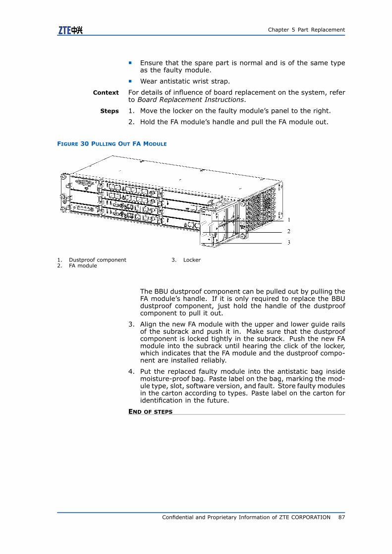
Chapter 5 Part Replacement
Ensure that the spare part is normal and is of the same typeas the faulty module.
Wear antistatic wrist strap.
Context For details of influence of board replacement on the system, referto Board Replacement Instructions.
Steps 1. Move the locker on the faulty module’s panel to the right.
2. Hold the FA module’s handle and pull the FA module out.
FIGURE 30 PULLING OUT FA MODULE
1. Dustproof component2. FA module
3. Locker
The BBU dustproof component can be pulled out by pulling theFA module’s handle. If it is only required to replace the BBUdustproof component, just hold the handle of the dustproofcomponent to pull it out.
3. Align the new FA module with the upper and lower guide railsof the subrack and push it in. Make sure that the dustproofcomponent is locked tightly in the subrack. Push the new FAmodule into the subrack until hearing the click of the locker,which indicates that the FA module and the dustproof compo-nent are installed reliably.
4. Put the replaced faulty module into the antistatic bag insidemoisture-proof bag. Paste label on the bag, marking the mod-ule type, slot, software version, and fault. Store faulty modulesin the carton according to types. Paste label on the carton foridentification in the future.
END OF STEPS
Confidential and Proprietary Information of ZTE CORPORATION 87

ZXSDR BS8900 GU360 Maintenance Guide
Subrack ReplacementSubrack Replacement Instructions
Table 21 lists the influence of subrack replacement on the system.
TABLE 21 INFLUENCE OF SUBRACK REPLACEMENT ON SYSTEM
Subrack Functions Influence onSystem
PDM subrack Implementing powerdistribution for the RFcabinet and BC8910DC cabinet, andpower switch control.
Replacing the PDMsubrack will cause thecabinet to power offand all services tointerrupt.
Fan subrack Implementing heatdissipation for thecabinet.
Replacing the fansubrack will cause thefan to stop running,but it has no influenceon services.
Lightning protectionsubrack
Implementinglightning protectionfor input/outputsignal.
Replacing thelightning protectionsubrack will causeall services tointerrupt and thealarm monitoring tointerrupt.
B121 power supply Implementing powerconversion andallocation for BC8910AC cabinet.
Replacing the B121power supply willcause the cabinetto power off and allservices to interrupt.
BBU subrack ImplementingAbis/Iub interfacefunctions, signalingprocessing, basebandprocessing, and localand remote operationand maintenance;monitoring workingstatus; reportingalarm information.
Replacing BBU willcause all services tointerrupt.
88 Confidential and Proprietary Information of ZTE CORPORATION

Chapter 5 Part Replacement
Subrack Functions Influence onSystem
Battery Standby battery,supporting theequipment runningwhen the equipmentis power off.
If the system adoptsexternal powersupply, then replacingthe battery hasno influence onequipments.
Heat exchanger Implementing heatdissipation for thecabinet
Replacing the heatexchanger has noinfluence on serviceswithin a short periodof time. However,in low temperature,it will influence theheating effect insideequipment.
When replacing a subrack, the following items should be noticed:
Strictly follow operation specifications to avoid misoperation.
Test or verify relevant functions of the new subrack to ensurethat the replacement is successful.
Operation personnel should wear antistatic wrist strap or anti-static glove when replacing the subrack. The grounding termi-nal of the antistatic wrist strap must be grounded reliably.
The average system maintenance (replacement) time is lessthan 0.5 hour.
Replacing B121 Power Supply
Prerequisites Through fault observation and analysis, locate the module faultand decide whether the module should be replaced.
Prepare antistatic bag, moisture-proof bag, carton, and severallabels.
Ensure that the spare part is normal and is of the same typeas the faulty module.
Record cable positions on the panel of the module to be re-placed. After the module replacement is completed, these ca-bles should be inserted to their original positions.
Wear antistatic wrist strap.
Context The BC8910 cabinet AC configuration adopts B121 power supplyto implement power supply conversion and allocation. To replaceB121 power supply, the cabinet should be powered off, which willcause all services to interrupt. Thus permission from relevanttechnical personnel must be obtained before performing the op-eration.
Steps 1. Make the cabinet power off. For power-off operation details,refer to Power-on/off Check in ZXSDR BS8900 GU360 (V4.00)Indoor GSM&UMTS Dual Mode Macro Node B Hardware Instal-lation Guide.
Confidential and Proprietary Information of ZTE CORPORATION 89

ZXSDR BS8900 GU360 Maintenance Guide
2. Pull out cables at the back of the cabinet. Record the cableconnection positions.
3. Loosen the four fastening screws on the power subrack’smounting flange, hold the subrack bottom, and pull it outgently.
4. Insert the new subrack into the shelf, and tighten the fasteningscrews.
5. Reinstall cables according to recorded cable connection posi-tions.
6. Make the cabinet power on. For power-on operation details,refer to Power-on/off Check in ZXSDR BS8900 GU360 (V4.00)Indoor GSM&UMTS Dual Mode Macro Node B Hardware Instal-lation Guide.
7. Put the replaced faulty module into the antistatic bag insidemoisture-proof bag. Paste label on the bag, marking the typeand fault. Store it in the carton. Paste label on the carton foridentification in the future.
END OF STEPS
Replacing PDM Subrack
Prerequisites Through fault observation and analysis, locate the module faultand decide whether the module should be replaced.
Prepare antistatic bag, moisture-proof bag, carton, and severallabels.
Ensure that the spare part is normal and is of the same typeas the faulty module.
Record cable positions on the panel of the module to be re-placed. After the module replacement is completed, these ca-bles should be inserted to their original positions.
Wear antistatic wrist strap.
Context The DC configuration of RF cabinet and BC8910 cabinet adoptsPDM subrack to implement power distribution inside cabinet. Toreplace the PDM subrack, the cabinet should be power off, whichwill cause all services to interrupt. Thus permission from relevanttechnical personnel must be obtained before performing the oper-ation.
Steps 1. Make the cabinet power off.
For power-off operation details, refer to Power-on/off Check inZXSDR BS8900 GU360 (V4.00) Indoor GSM&UMTS Dual ModeMacro Node B Hardware Installation Guide.
2. Pull out cables at the back of the cabinet. Record the cableconnection positions.
3. Loosen the fastening screws on the subrack’s panel, hold thesubrack bottom, and pull it out gently.
4. Insert the new subrack into the shelf, and tighten the fasteningscrews.
90 Confidential and Proprietary Information of ZTE CORPORATION

Chapter 5 Part Replacement
5. Reinstall cables according to recorded cable connection posi-tions.
6. Make the cabinet power on.
For power-on operation details, refer to Power-on/off Check inZXSDR BS8900 GU360 (V4.00) Indoor GSM&UMTS Dual ModeMacro Node B Hardware Installation Guide.
7. Put the replaced faulty module into the antistatic bag insidemoisture-proof bag. Paste label on the bag, marking the typeand fault. Store it in the carton. Paste label on the carton foridentification in the future.
END OF STEPS
Replacing Fan Subrack
Prerequisites Through fault observation and analysis, locate the module faultand decide whether the module should be replaced.
Prepare antistatic bag, moisture-proof bag, carton, and severallabels.
Ensure that the spare part is normal and is of the same typeas the faulty module.
Record cable positions on the panel of the module to be re-placed. After the module replacement is completed, these ca-bles should be inserted to their original positions.
Wear antistatic wrist strap.
Context For details of influence of subrack replacement on the system, re-fer to Subrack Replacement Instructions. The following takes thefan subrack of RC8910 for example to explain how to replace thefan subrack. The fan subrack replacement methods of RC8911 andRC8931 are the same.
Steps 1. Turn off the fan subrack’s power supply. The power switch ison the power distribution subrack’s front panel.
2. Unplug cables on the front panel of the fan subrack.
3. Loosen the fastening screws on the subrack’s panel, use onehand to pull the subrack’s handle out and the other hand tohold the subrack and pull it out gently.
Confidential and Proprietary Information of ZTE CORPORATION 91
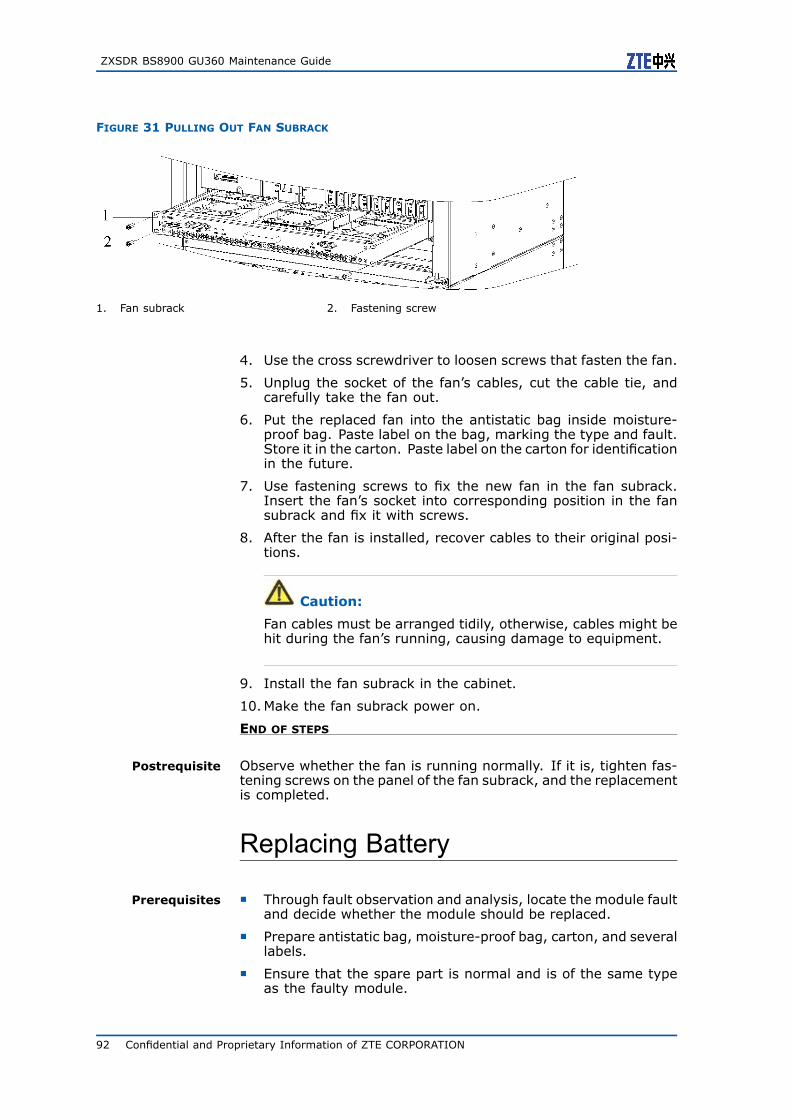
ZXSDR BS8900 GU360 Maintenance Guide
FIGURE 31 PULLING OUT FAN SUBRACK
1. Fan subrack 2. Fastening screw
4. Use the cross screwdriver to loosen screws that fasten the fan.
5. Unplug the socket of the fan’s cables, cut the cable tie, andcarefully take the fan out.
6. Put the replaced fan into the antistatic bag inside moisture-proof bag. Paste label on the bag, marking the type and fault.Store it in the carton. Paste label on the carton for identificationin the future.
7. Use fastening screws to fix the new fan in the fan subrack.Insert the fan’s socket into corresponding position in the fansubrack and fix it with screws.
8. After the fan is installed, recover cables to their original posi-tions.
Caution:
Fan cables must be arranged tidily, otherwise, cables might behit during the fan’s running, causing damage to equipment.
9. Install the fan subrack in the cabinet.
10.Make the fan subrack power on.
END OF STEPS
Postrequisite Observe whether the fan is running normally. If it is, tighten fas-tening screws on the panel of the fan subrack, and the replacementis completed.
Replacing Battery
Prerequisites Through fault observation and analysis, locate the module faultand decide whether the module should be replaced.
Prepare antistatic bag, moisture-proof bag, carton, and severallabels.
Ensure that the spare part is normal and is of the same typeas the faulty module.
92 Confidential and Proprietary Information of ZTE CORPORATION

Chapter 5 Part Replacement
Record cable positions on the panel of the module to be re-placed. After the module replacement is completed, these ca-bles should be inserted to their original positions.
Wear antistatic wrist strap.
Context Batteries can be configured in RC8911, RC8931, and PC8910. Fordetails of influence of battery replacement on the system, refer toSubrack Replacement Instructions.
Steps 1. Disconnect the input air break switch of B121 power supply.
2. Unplug the charging/discharging cable between the batteryand B121 power supply, unplug the power cable of the bat-tery’s heating film, and record the cable connection positions.
3. Take the battery from the tray of the battery shelf.
4. Put the spare battery on the tray of the battery shelf.
5. Connect the charging/discharging cable and the power cableof the battery’s heating film according to recorded cable con-nection positions.
6. Connect the input air break switch of B121 power supply.
END OF STEPS
Replacing Heat Exchanger
Prerequisites Through fault observation and analysis, locate the module faultand decide whether the module should be replaced.
Prepare antistatic bag, moisture-proof bag, carton, and severallabels.
Ensure that the spare part is normal and is of the same typeas the faulty module.
Record cable positions on the panel of the module to be re-placed. After the module replacement is completed, these ca-bles should be inserted to their original positions.
Wear antistatic wrist strap.
Context BC8910 adopts the heat exchanger to dissipate heat. For detailsof influence of heat exchanger replacement on the system, referto Subrack Replacement Instructions.
Steps 1. Turn off the heat exchanger’s power supply.
2. Unplug the power cable and the monitoring cable at the sideof the heat exchanger.
3. Loosen the four fastening screws on the heat exchanger’smounting flange, use one hand to pull the heat exchanger’shandle out and the other hand to hold the heat exchanger andpull it out.
4. Fix the spare heat exchanger in the cabinet with fasteningscrews.
5. Connect the power cable and the monitoring cable of the heatexchanger.
Confidential and Proprietary Information of ZTE CORPORATION 93

ZXSDR BS8900 GU360 Maintenance Guide
6. Turn on the heat exchanger’s power supply.
7. Put the replaced module into the antistatic bag inside moisture-proof bag. Paste label on the bag, marking the type and fault.Store it in the carton. Paste label on the carton for identificationin the future.
END OF STEPS
Postrequisite Observe indicators on the heat exchanger. If status of indicatorsare normal, then the replacement is successful.
Replacing Lightning ProtectionSubrack
Prerequisites Through fault observation and analysis, locate the module faultand decide whether the module should be replaced.
Prepare antistatic bag, moisture-proof bag, carton, and severallabels.
Ensure that the spare part is normal and is of the same typeas the faulty module.
Record cable positions on the panel of the module to be re-placed. After the module replacement is completed, these ca-bles should be inserted to their original positions.
Wear antistatic wrist strap.
Context The lightning protection subrack is installed in the BC8910 cabinet.For details of influence of lightning protection subrack replacementon the system, refer to Subrack Replacement Instructions.
Steps 1. Unplug E1 cable and dry contact cable on the lightning protec-tion subrack. Record the cable connection positions.
2. Loosen the four fastening screws on the lightning protectionsubrack’s mounting flange, use one hand to hold the subrack,and take the subrack out.
3. Fix the spare lightning protection subrack in the cabinet withfastening screws.
4. Connect various cables of the lightning protection subrack ac-cording to recorded cable connection positions.
5. Put the replaced faulty module into the antistatic bag insidemoisture-proof bag. Paste label on the bag, marking the typeand fault. Store it in the carton. Paste label on the carton foridentification in the future.
END OF STEPS
94 Confidential and Proprietary Information of ZTE CORPORATION

Chapter 5 Part Replacement
Replacing BBU
Prerequisites Through fault observation and analysis, locate the module faultand decide whether the module should be replaced.
Prepare antistatic bag, moisture-proof bag, carton, and severallabels.
Ensure that the spare part is normal and is of the same typeas the faulty module.
Record cable positions on the panel of the module to be re-placed. After the module replacement is completed, these ca-bles should be inserted to their original positions.
Wear antistatic wrist strap.
Context Replacing the BBU subrack will cause all services to interrupt, thuspermission from relevant technical personnel must be obtained be-fore performing the operation.
Steps 1. Turn off the BBU subrack’s power supply. The power switch ison the front panel of PDM subrack or B121 power subrack.
2. Unplug cables of all boards in the BBU subrack.
3. Loosen the fastening screws on the BBU subrack’s panel, holdthe subrack bottom, and pull it out gently.
FIGURE 32 REPLACING BBU
1. Fastening screw
4. Insert the spare subrack into the shelf, and tighten the fasten-ing screws.
5. Reinstall cables for each board.
6. Make the BBU power on.
7. Put the replaced faulty module into the antistatic bag insidemoisture-proof bag. Paste label on the bag, marking the typeand fault. Store it in the carton. Paste label on the carton foridentification in the future.
END OF STEPS
Confidential and Proprietary Information of ZTE CORPORATION 95

ZXSDR BS8900 GU360 Maintenance Guide
Postrequisite Observe indicators on each board of the BBU. If the board’s self-test succeeds, indicators are normal and services are recovered,then the replacement is successful.
If the board’s self-test fails, in other words, the self-test repeatsor the final display result is abnormal, relevant services are notrecovered, then the replacement fails. Check whether the sparepart is damaged or the fault is not in the board. Operation per-sonnel can observe alarms at foreground and background to findthe fault cause.
96 Confidential and Proprietary Information of ZTE CORPORATION

A p p e n d i x A
Data Record Forms
Table of ContentsDaily Maintenance Record Form...........................................97Monthly Maintenance Record Form.......................................99Quarterly Maintenance Record Form................................... 100Biannual Maintenance Record Form.................................... 101Yearly Maintenance Record Form ....................................... 102Part Replacement Data Record Form .................................. 104Emergency Troubleshooting Record Form............................ 105
Daily Maintenance RecordFormBS8900 GU360 maintenance personnel should make the dailymaintenance record form every day. Table 22 shows the dailymaintenance record form.
Confidential and Proprietary Information of ZTE CORPORATION 97
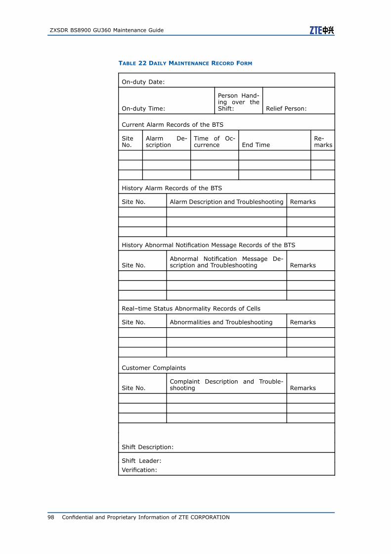
ZXSDR BS8900 GU360 Maintenance Guide
TABLE 22 DAILY MAINTENANCE RECORD FORM
On-duty Date:
On-duty Time:
Person Hand-ing over theShift: Relief Person:
Current Alarm Records of the BTS
SiteNo.
Alarm De-scription
Time of Oc-currence End Time
Re-marks
History Alarm Records of the BTS
Site No. Alarm Description and Troubleshooting Remarks
History Abnormal Notification Message Records of the BTS
Site No.Abnormal Notification Message De-scription and Troubleshooting Remarks
Real–time Status Abnormality Records of Cells
Site No. Abnormalities and Troubleshooting Remarks
Customer Complaints
Site No.Complaint Description and Trouble-shooting Remarks
Shift Description:
Shift Leader:
Verification:
98 Confidential and Proprietary Information of ZTE CORPORATION

Appendix A Data Record Forms
Monthly MaintenanceRecord FormBS8900 GU360 maintenance personnel should make the monthlymaintenance record form every month. Table 23 shows themonthly maintenance record form.
Confidential and Proprietary Information of ZTE CORPORATION 99
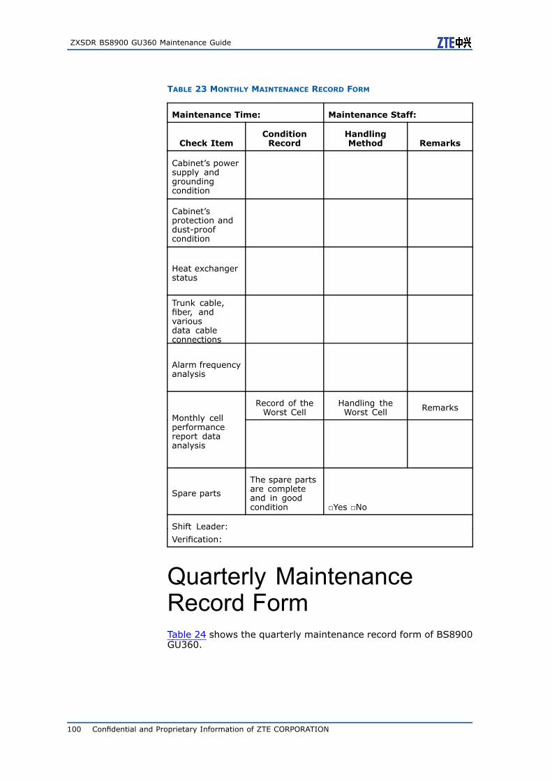
ZXSDR BS8900 GU360 Maintenance Guide
TABLE 23 MONTHLY MAINTENANCE RECORD FORM
Maintenance Time: Maintenance Staff:
Check ItemConditionRecord
HandlingMethod Remarks
Cabinet’s powersupply andgroundingcondition
Cabinet’sprotection anddust-proofcondition
Heat exchangerstatus
Trunk cable,fiber, andvariousdata cableconnections
Alarm frequencyanalysis
Record of theWorst Cell
Handling theWorst Cell Remarks
Monthly cellperformancereport dataanalysis
Spare parts
The spare partsare completeand in goodcondition Yes No
Shift Leader:
Verification:
Quarterly MaintenanceRecord FormTable 24 shows the quarterly maintenance record form of BS8900GU360.
100 Confidential and Proprietary Information of ZTE CORPORATION

Appendix A Data Record Forms
TABLE 24 QUARTERLY MAINTENANCE RECORD FORM
Maintenance Time: Maintenance Staff:
Category Check Item Check Result Remarks
The coveragetest result isnormal Yes No
The conversa-tion test resultis normal Yes No
Conversation,coverage, andhandover tests
The handovertest result isnormal Yes No
The fans arerunning nor-mally Yes No
The boards arerunning nor-mally Yes No
Main equipmentcheck
The heat ex-changer is run-ning normally Yes No
The RF cableconnections arenormal Yes No
Cable connec-tion check
The GPS cableconnections arenormal Yes No
Shift Leader:
Verification:
Biannual MaintenanceRecord FormTable 25 shows the biannual maintenance record form of BS8900GU360.
Confidential and Proprietary Information of ZTE CORPORATION 101

ZXSDR BS8900 GU360 Maintenance Guide
TABLE 25 BIANNUAL MAINTENANCE RECORD FORM
Maintenance Time: Maintenance Staff:
Category Check Item Check Result Remarks
The fan shelf isclean Yes No
Equipmentcleanness
The shutter isclean Yes No
Board diagnosisand test
The test resultis normal Yes No
Shift Leader:
Verification:
Yearly Maintenance RecordFormTable 26 shows the yearly maintenance record form of BS8900GU360.
102 Confidential and Proprietary Information of ZTE CORPORATION

Appendix A Data Record Forms
TABLE 26 YEARLY MAINTENANCE RECORD FORM
Maintenance Time: Maintenance Staff:
Category Check Item Check Result Remarks
Measuring theoutput powerof power ampli-fiers
Output power:
Main equipmentcheck
Measuring theSWR SWR:
Board change-over test
The CC boardchangeover isnormal
Yes No
The lightningprotector is nor-mal
Yes No
The groundingcable is reliable Yes No
Grounding andlightning pro-tection check
Testing thegrounding re-sistance
Grounding re-sistance:
The antennafeeder interfaceis normal
Yes No
The antennatower amplifieris firm
Yes No
The directionalantenna tilt sat-isfies require-ments
Yes NoAntenna feedersystem check
The waterproofconditions ofantenna feederinterface andlightning pro-tective ground-ing clip are nor-mal
Yes No
Confidential and Proprietary Information of ZTE CORPORATION 103

ZXSDR BS8900 GU360 Maintenance Guide
Maintenance Time: Maintenance Staff:
Category Check Item Check Result Remarks
The iron toweris normal Yes No
The pole is nor-mal Yes No
The transmis-sion equip-ments are run-ning normally
Yes No
Other checks
The batteriesare normal Yes No
Shift Leader:
Verification:
Part Replacement DataRecord FormTable 27 shows the part replacement data record form.
104 Confidential and Proprietary Information of ZTE CORPORATION

Appendix A Data Record Forms
TABLE 27 PART REPLACEMENT DATA RECORD FORM
Module/Cable Replacement Data Record Form
BTS No.: Maintenance Staff:
Board/Ca-ble Type
ModuleSlot/Ca-ble Con-nectionPosition
Time ofFault Oc-currence
Time ofReplace-ment
FaultyMod-ule/Ca-ble Se-rial No.
Replac-ing Mod-ule/Ca-ble Se-rial No.
Emergency TroubleshootingRecord FormTable 28 shows the emergency troubleshooting record form.
Confidential and Proprietary Information of ZTE CORPORATION 105
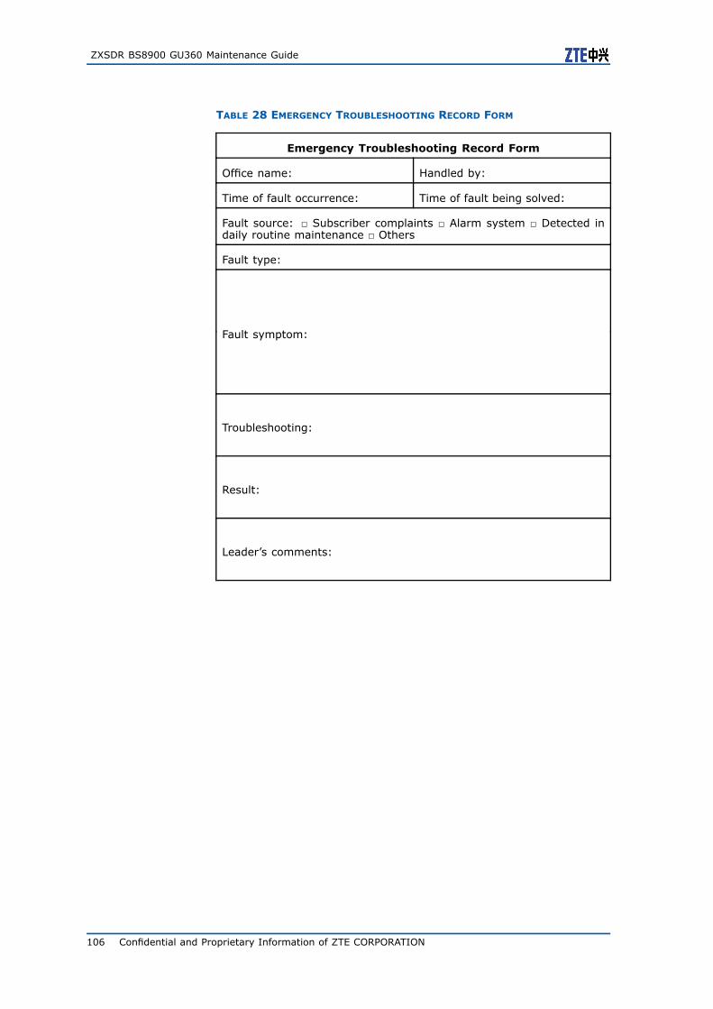
ZXSDR BS8900 GU360 Maintenance Guide
TABLE 28 EMERGENCY TROUBLESHOOTING RECORD FORM
Emergency Troubleshooting Record Form
Office name: Handled by:
Time of fault occurrence: Time of fault being solved:
Fault source: Subscriber complaints Alarm system Detected indaily routine maintenance Others
Fault type:
Fault symptom:
Troubleshooting:
Result:
Leader’s comments:
106 Confidential and Proprietary Information of ZTE CORPORATION
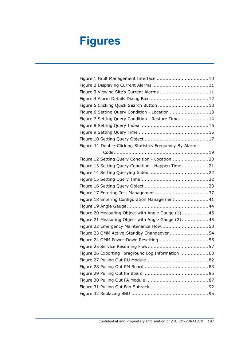
Figures
Figure 1 Fault Management Interface ...................................10
Figure 2 Displaying Current Alarms ......................................11
Figure 3 Viewing Site’s Current Alarms .................................11
Figure 4 Alarm Details Dialog Box ........................................12
Figure 5 Clicking Quick Search Button ..................................13
Figure 6 Setting Query Condition - Location ..........................13
Figure 7 Setting Query Condition - Restore Time....................14
Figure 8 Setting Query Index ..............................................16
Figure 9 Setting Query Time ...............................................16
Figure 10 Setting Query Object ...........................................17
Figure 11 Double-Clicking Statistics Frequency By Alarm
Code................................................................19
Figure 12 Setting Query Condition - Location.........................20
Figure 13 Setting Query Condition - Happen Time..................21
Figure 14 Setting Querying Index ........................................22
Figure 15 Setting Query Time..............................................22
Figure 16 Setting Query Object ...........................................23
Figure 17 Entering Test Management....................................37
Figure 18 Entering Configuration Management.......................41
Figure 19 Angle Gauge .......................................................44
Figure 20 Measuring Object with Angle Gauge (1) ..................45
Figure 21 Measuring Object with Angle Gauge (2) ..................45
Figure 22 Emergency Maintenance Flow................................50
Figure 23 OMM Active-Standby Changeover ..........................54
Figure 24 OMM Power-Down Resetting .................................55
Figure 25 Service Resuming Flow.........................................57
Figure 26 Exporting Foreground Log Information ...................60
Figure 27 Pulling Out RU Module..........................................82
Figure 28 Pulling Out PM Board ...........................................83
Figure 29 Pulling Out FS Board ............................................85
Figure 30 Pulling Out FA Module ..........................................87
Figure 31 Pulling Out Fan Subrack .......................................92
Figure 32 Replacing BBU ....................................................95
Confidential and Proprietary Information of ZTE CORPORATION 107

ZXSDR BS8900 GU360 Maintenance Guide
This page is intentionally blank.
108 Confidential and Proprietary Information of ZTE CORPORATION
Tables
Table 1 Safety Symbols Description....................................... 1
Table 2 Daily Routine Maintenance Items ............................... 9
Table 3 Monthly Routine Maintenance Items ..........................18
Table 4 Quarterly Routine Maintenance Items ........................27
Table 5 Normal Status of RU Panel Indicators ........................29
Table 6 Normal Status of CC Panel Indicators ........................29
Table 7 Normal Status of UBPG (or BPC) Panel Indicators........31
Table 8 Normal Status of FS Panel Indicators.........................31
Table 9 Normal Status of SA Panel Indicators ........................32
Table 10 Abnormal Status of RU Panel Indicators ...................32
Table 11 Abnormal Status of CC Panel Indicators ...................32
Table 12 Abnormal Status of UBPG (or BPC) Panel Indicators...33
Table 13 Abnormal Status of FS Panel Indicators....................33
Table 14 Abnormal Status of SA Panel Indicators ...................34
Table 15 Biannual Routine Maintenance Items .......................36
Table 16 Yearly Routine Maintenance Items...........................38
Table 17 Fault Symptom and Details.....................................49
Table 18 Rectifier Fault Analysis and Troubleshooting..............76
Table 19 Replaceable Part List .............................................79
Table 20 Influence of Board Replacement on System ..............80
Table 21 Influence Of Subrack Replacement on System...........88
Table 22 Daily Maintenance Record Form ..............................98
Table 23 Monthly Maintenance Record Form ........................ 100
Table 24 Quarterly Maintenance Record Form ...................... 101
Table 25 Biannual Maintenance Record Form ....................... 102
Table 26 Yearly Maintenance Record Form........................... 103
Table 27 Part Replacement Data Record Form...................... 105
Table 28 Emergency Troubleshooting Record Form ............... 106
Confidential and Proprietary Information of ZTE CORPORATION 109


![Rapport Concept de format des messages selon le standard ... · V2.31 dito 28.11.2016 Adaption action=10 de Transmission à Transfert et ... M. Stingelin V4.00, 28.6.2012 [12] ...](https://static.fdocuments.us/doc/165x107/5adcf21d7f8b9a595f8c3938/rapport-concept-de-format-des-messages-selon-le-standard-dito-28112016-adaption.jpg)