ZX2 Short Manual - downloads.omron.de Senso… · ZX2 Short Manual.doc ... The LOW judgement output...
12
ZX2 Short Manual.doc Page 1 of 12 Short Manual
Transcript of ZX2 Short Manual - downloads.omron.de Senso… · ZX2 Short Manual.doc ... The LOW judgement output...

ZX2 Short Manual.doc Page 1 of 12
Short Manual
ZX2 Short Manual.doc Page 2 of 12
1 Safety precautions and correct use Please refer to the full ZX2 user manual for the detailed explanations of the safety precautions and the correct use.
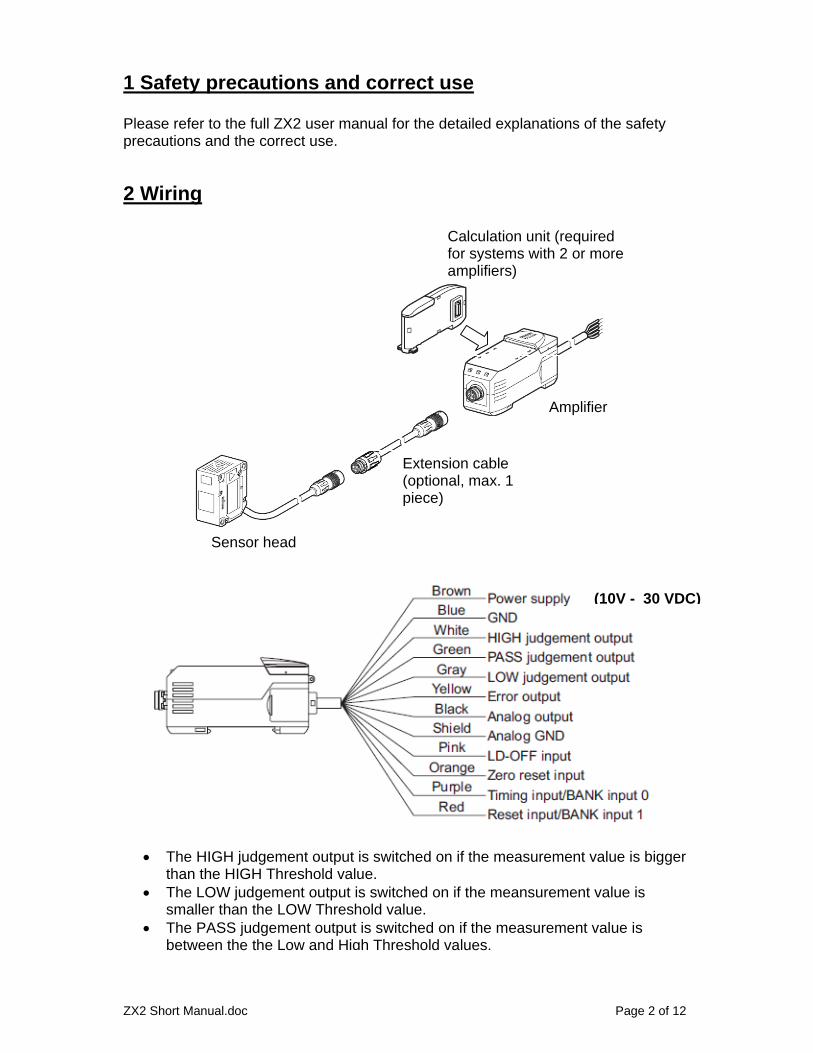
2 Wiring
Amplifier
Calculation unit (required for systems with 2 or more amplifiers)
Extension cable (optional, max. 1 piece)
Sensor head
(10V - 30 VDC)
The HIGH judgement output is switched on if the measurement value is bigger than the HIGH Threshold value.
The LOW judgement output is switched on if the meansurement value is smaller than the LOW Threshold value.
The PASS judgement output is switched on if the measurement value is between the the Low and High Threshold values.
ZX2 Short Manual.doc Page 3 of 12
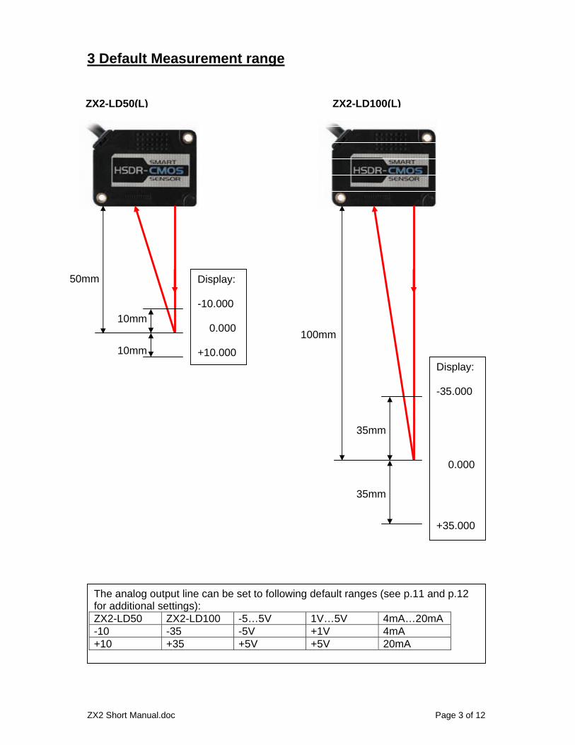
3 Default Measurement range
35mm
35mm
100mm
10mm
10mm
50mm
ZX2-LD50(L) ZX2-LD100(L)
Display: -10.000 0.000 +10.000
Display: -35.000 0.000 +35.000
The analog output line can be set to following default ranges (see p.11 and p.12 for additional settings): ZX2-LD50 ZX2-LD100 -5…5V 1V…5V 4mA…20mA -10 -35 -5V +1V 4mA +10 +35 +5V +5V 20mA

ZX2 Short Manual.doc Page 4 of 12
4 Display in RUN mode
H
Press right or left button
Orange subdisplay
Displays the selected bank
Displays the High Threshold
Displays the Low Threshold
Displays either the current or voltage at the analog output
Displays the current resolution
Displays the current measurement value
L

ZX2 Short Manual.doc Page 5 of 12
5 Functions in RUN mode:
Set the current value to ZERORESET
ZERO LED turns on
Press the “down arrow” button for 3 seconds. In order to switch off again, press the up- and down arrow simultaneously for 3 seconds.
Activate the Key Lock.
Press both “arrow left” and “arrow right” buttons simultaneously for 3 seconds to activate or deactivate the Key Lock function.
Activate “Smart Tuning”
Press the SMART button for 1 second to activate the Single Smart Tuning function, 2 seconds to activate the Multi Smart Tuning function and 5 seconds to activate the Active Smart Tuning function.
See page 9 for details!

ZX2 Short Manual.doc Page 6 of 12
6 Setup mode Pressing and holding the “MENU/SET” button for 3 seconds changes the mode of the amplifier to the setting mode (pressing again for 3s moves back to RUN mode):
Below you see the navigation through all menus (Details switched on, all other options switched off) by pressing the left/right arrow button. You change the options by pressing the up and down arrow buttons and confirm with the Menu/Set button:
MENU LED Indicates setup mode
Press for 3 seconds
Selection of one of 4 banks.
Setup the response time. The response time is determined by the number of averages multiplied with the cycle time of one measurement.
Setup the High Threshold for the digital outputs.
Setup the Low Threshold for the digital outputs.
Detail*
* Detail: These menus are only displayed if “Detail” is switched “ON”
Bank*
* Bank: These parameters are set for the current bank. All other parameters are set globally.
Bank
Bank

ZX2 Short Manual.doc Page 7 of 12
Setup the Hysteresis.
Setup the scale of the display and analog output value. (All settings (S1/S2) for the scaling are stored in the bank data. See p. 11.)
Setup the Hold function. See p. 10.
Setup of the analog output either voltage or current and the output range.
Setup the behavior of the analog output in the case that the sensor is in error state (resp. not able to obtain a measurement value. Display: E-dark). See p. 12.
Setup the clamp value for the analog output (only valid if RStOUT is set to “Clamp”).
Detail
Detail
Detail
Detail
Detail
Bank
Bank

ZX2 Short Manual.doc Page 8 of 12
Setup the on-delay of the digital outputs. See the full user manual for details.
Setup the off-delay of the digital outputs. See the full user manual for details.
Setup the way how the zero-reset value is stored (permanently or volatile).
Setup the zero-reset value for the zero-reset function.
Setup the function of the 2 input terminals. Either timing and reset inputs or bank select inputs.
Setup the menu between simple (“Off”) and detailed (“On”). If “Detail” is switched to “On” all menu items are displayed.
Reset the sensor to the factory defaults. All user defined settings are deleted.
Detail
Detail
Detail
Detail
Detail

ZX2 Short Manual.doc Page 9 of 12
7 Smart Tuning Smart Tuning sets the optimum parameters for the chosen response time (“Speed” setting) and the measurement object automatically. The ZX2 has 3 different Smart Tuning modes: Single Smart Tuning: Single Smart Tuning is used if the objects in the final application always have the same surface characteristic. Place the measurement object in front of the sensor and press the “Smart” button for 1s:
Multi Smart Tuning: Multi Smart Tuning is used if there are a couple of different objects in the final application which are varying in the surface characteristics. Place one after another of the measurement objects in front of the sensor and press each time the “Smart” button for 2s:
Active Smart Tuning: Active Smart Tuning is used if the object(s) is (are) moving in the final application. The Smart Active tuning is activated by pressing the Smart button for 5s then the object(s) is (are) passed by in front of the sensor and finally the Smart button is again pressed for 5s in order to stop the tuning process.
Press for 1 second
Press for 2 seconds
Press for 5 seconds
ZX2 Short Manual.doc Page 10 of 12
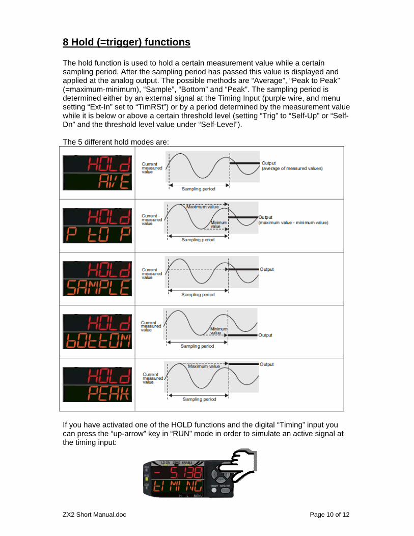
8 Hold (=trigger) functions The hold function is used to hold a certain measurement value while a certain sampling period. After the sampling period has passed this value is displayed and applied at the analog output. The possible methods are “Average”, “Peak to Peak” (=maximum-minimum), “Sample”, “Bottom” and “Peak”. The sampling period is determined either by an external signal at the Timing Input (purple wire, and menu setting “Ext-In” set to “TimRSt”) or by a period determined by the measurement value while it is below or above a certain threshold level (setting “Trig” to “Self-Up” or “Self-Dn” and the threshold level value under “Self-Level”). The 5 different hold modes are:
If you have activated one of the HOLD functions and the digital “Timing” input you can press the “up-arrow” key in “RUN” mode in order to simulate an active signal at the timing input:

ZX2 Short Manual.doc Page 11 of 12
9 Scaling The scaling function is used to both
1. adjust the display value. 2. adjust the analog output value.
With scaling it’s possible to set the values for the upper and lower measurement range limits:
The easiest way to understand how the setting is done is using an example: The default range of the sensor is +/-10 mm (e.g. for the ZX2-LD50). For the application only the range from 0..5mm is required and the display should be 50..55mm, then you set following values to S1 and S2:
S1-bef S1-Aft S2-bef S2-Aft 0 50 5 55
The Analog output always has the full swing for the values specified for the S1-Aft and S2-Aft values. Here: The analog output is -5V for the display of 50 and +5V for the display of 55 (if the analog output is configured for -5V..5V, for the other ranges 1..5V and 4..20mA this is valid accordingly). All the values for S1 and S2 are stored in the bank data. After scaling the threshold values for the High/Pass/Low judgement must be set accordingly to the display values (the stored threshold values remain unchanged when scaling is performed).

ZX2 Short Manual.doc Page 12 of 12
10 Setting for the analog output in case of measurement error If no measurement is possible, e.g. because no object is in front of the sensor inside of the measurement range (display: E-dark), the sensor can be configured for the analog output either to issue:
a predefined value (Setting: Clamp and Clamp value) or the value of the last valid measurement (setting “Keep”)
The setting is done in the menus:
or
Setting range: -5V..max. resp. 4mA..max.


![arXiv:1808.01865v1 [physics.ins-det] 12 Jul 2018 · The vibrations of the beam are measured at the tip and 55 mm away from the excitation using Omron ZX2-LD100 and ZX2-LD50 displacement](https://static.fdocuments.us/doc/165x107/5d511dff88c993662f8b5aef/arxiv180801865v1-12-jul-2018-the-vibrations-of-the-beam-are-measured-at.jpg)