Zweireihige Miniatur-Kugelumlaufeinheiten Baureihen … · First slide the carriage onto the...
21
Zweireihige Miniatur-Kugelumlaufeinheiten Baureihen TKDM/KWEM KWEM..-LZM KWEM..-MKS Two-row miniature linear recirculating ball bearing and guideway assemblies Series TKDM/KWEM KWEM..-LZM KWEM..-MKS 0013AF4 Montage- und Wartungsanleitung Fitting and maintenance manual
Transcript of Zweireihige Miniatur-Kugelumlaufeinheiten Baureihen … · First slide the carriage onto the...

ZweireihigeMiniatur-KugelumlaufeinheitenBaureihenTKDM/KWEMKWEM..-LZMKWEM..-MKS
Two-row miniature linearrecirculating ball bearing andguideway assembliesSeriesTKDM/KWEMKWEM..-LZMKWEM..-MKS
0013
AF4
Montage- und WartungsanleitungFitting and maintenance manual

2 MON 28
SeiteMontageplatz/Montagewerkzeuge ........................... 3
Anschlaghöhen und Eckenradien kontrollieren......... 4
Form- und Lagetoleranzen/Höhenversatz ................. 6
Form- und Lagetoleranzen/Höhenversatz: Faktor a ... 7
Parallelität der Anschlagflächen kontrollieren .......... 8
Lieferausführung kontrollieren ................................. 9
Befestigungsschrauben und Anziehdrehmomente ... 11
Führungswagen demontieren ................................... 13
Führungswagen montieren ....................................... 14
Vormontierte Kugelumlaufeinheiten einbauen ......... 15Schmierung.............................................................. 19
PageFitting area/fitting tools ........................................... 3
Checking of locating heights and corner radii........... 4
Geometrical tolerances/height offset....................... 6
Geometrical tolerances/height offset: Factor a......... 7
Checking the parallelism of the locating faces ......... 8
Checking the delivered condition............................. 9
Fasteners and tightening torques............................. 11
Dismantling of carriages .......................................... 13
Fitting of carriages ................................................... 14
Fitting of preassembled linear ball bearingand guideway assemblies........................................ 15Lubrication .............................................................. 19

MON 28 3
Montageplatz/Montagewerkzeuge
Achtung!Diese Anleitung gilt für Zweireihige Miniatur-Kugelumlaufeinheiten bestehend ausFührungsschiene TKDM (-W) und FührungswagenKWEM (-L, -C, -W, -WL, -WC, -LZM, -MKS).
Führungen nur danach einbauen!
In der Nähe des Montageplatzes nicht mitspanabhebenden oder stauberzeugenden Maschinen, Geräten, Anlagen arbeiten!
Verhindern, dass Verunreinigungen/Feuchtigkeit in die Einheiten gelangen! Sie beeinträchtigen die Funktion der Elemente erheblich und verringern ihre Gebrauchs-dauer nachhaltig!
Elemente nur mit vorgeschriebenen Werkzeugen montieren! Ungeeignete oder verschmutzte Werkzeuge können die Funktion und Gebrauchsdauer der Führungen erheblich verringern!
Die Schaeffler KG haftet nicht für Schäden am Produkt oder an der Umgebungskonstruktion durch fehlerhaften Einbau, nicht bestimmungsgemäßen Gebrauch undunsachgemäße Wartung der Elemente!
Fitting area/fitting tools
Attention!This manual applies to two-row miniature linearrecirculating ball bearing and guideway assemblieswith guideways TKDM (-W) and carriagesKWEM (-L, -C, -W, -WL, -WC, -LZM, -MKS).
The guidance systems should only be fittedin accordance with this manual.
Machines, devices or equipment which generate swarf or dust must not be used in the immediate vicinity ofthe fitting area.
It must be ensured that contaminants or moisture cannot penetrate the units. These impair the function and operating life of the elements considerably.
Elements should only be fitted using the tools specified and in a clean condition. Unsuitable or contaminated tools can reduce the function and operating life of the elements considerably.
Schaeffler KG accepts no liability for damage tothe product or adjacent construction resulting fromincorrect fitting, inappropriate use or incorrectmaintenance of the elements.

4 MON 28
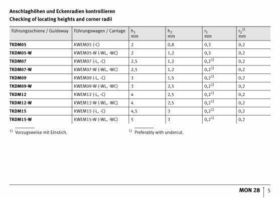
Anschlaghöhen und Eckenradien kontrollieren
Achtung!Die Anschlusskonstruktion muss sauber sein!
Schmutz beeinträchtigt die Genauigkeit und verringert die Gebrauchsdauer der Umlaufeinheit!
❑ Bohrungen und Anschlagkanten auf Gratbildung überprüfen; Grat mit Ölstein entfernen.
❑ Anschlaghöhen „h1, h2“ und Eckenradien „r1, r2“ nach Bild und Tabelle, Seite 5, überprüfen;Abweichungen korrigieren.
❑ Montageflächen reinigen.
Checking of locating heights and corner radii
Attention!The adjacent construction must be clean.
Contamination impairs the accuracy and operating life of the recirculating unit.
❑ Check the holes and locating edges for burrs; remove any burrs using an oilstone.
❑ Check the locating heights “h1, h2” and cornerradii “r1, r2” in accordance with the figureand table, page 5; correct any deviations.
❑ Clean the mounting surfaces.
r
h
1
1
r22h
0001
3AF5
MON 28 5
Anschlaghöhen und Eckenradien kontrollieren
Checking of locating heights and corner radii
Führungsschiene / Guideway Führungswagen / Carriage h1mm
h2mm
r1mm
r21)
mm
TKDM05 KWEM05 (-C) 2 0,8 0,3 0,2
TKDM05-W KWEM05-W (-WL, -WC) 2 1,2 0,3 0,2
TKDM07 KWEM07 (-L, -C) 2,5 1,2 0,21) 0,2
TKDM07-W KWEM07-W (-WL, -WC) 2,5 1,2 0,21) 0,2
TKDM09 KWEM09 (-L, -C) 3 1,5 0,21) 0,2
TKDM09-W KWEM09-W (-WL, -WC) 3 2,5 0,21) 0,2
TKDM12 KWEM12 (-L, -C) 4 2,5 0,21) 0,2
TKDM12-W KWEM12-W (-WL, -WC) 4 2,5 0,21) 0,2
TKDM15 KWEM15 (-L, -C) 4,5 3 0,21) 0,2
TKDM15-W KWEM15-W (-WL, -WC) 5 3 0,21) 0,2
1) Vorzugsweise mit Einstich. 1) Preferably with undercut.

6 MON 28
Form- und Lagetoleranzen/Höhenversatz
❑ Form- und Lagetoleranzen nach Bild kontrollieren;abweichende Flächen bearbeiten.
❑ Höhenversatz �H (�m) ermitteln, nach Gleichungberechnen und mit Messwert vergleichen;Flächen gegebenenfalls bearbeiten.– b (mm) ist Mittenabstand.– a nach Tabelle, Seite 7.
�H a b= ⋅
Geometrical tolerances/height offset
❑ Check the geometrical tolerances in accordance with the figure; machine any non-compliant surfaces.
❑ Determine the height offset �H (�m), calculatethe value using the formula and compare it with the measured value; machine the surface as appropriate.– b (mm) is the centre distance.– a is in accordance with table, page 7.
�H a b= ⋅ 1) Nicht konvex (für alle Bearbeitungsflächen).
1) Not convex (for all machined surfaces).
A
AAB B
A
b
AA
bz x
y
x z
y
tt
tt
t
t
�H
�H
1)
t1)
0001
3AFD

MON 28 7
Form- und Lagetoleranzen/Höhenversatz: Faktor a
Geometrical tolerances/height offset: Factor a
Kurzzeichen / Designation Faktor a / Factor aVorspannungsklassen / Preload classes
Führungsschiene / Guideway Führungswagen / Carriage V0 V1
TKDM05 (-W) KWEM05 (-C, -W, -WC) 0,1 0,01
TKDM07 (-W) KWEM07 (-L, -C, -W, -WL, -WC) 0,125 0,02
TKDM09 (-W) KWEM09 (-L, -C, -W, -WL, -WC) 0,175 0,03
TKDM12 (-W) KWEM12 (-L, -C, -W, -WL, -WC) 0,25 0,06
TKDM15 (-W) KWEM15 (-L, -C, -W, -WL, -WC) 0,3 0,15

8 MON 28
Parallelität der Anschlagflächen kontrollieren
Achtung!Bei Höchstwerten nach Tabelle kann der Verschiebe-widerstand steigen!
❑ Bei zwei definierten Anschlagflächen die Parallelität t nach Bild und Tabelle prüfen.
Bei Abweichung Auflage- und Anschlagflächen für die Schienen an der Anschlusskonstruktion nacharbeiten.
1) Nicht konvex (für alle Bearbeitungsflächen).
Checking the parallelism of the locating faces
Attention!If the highest values according to the table are reached, the displacement resistance may increase.
❑ If there are two defined locating surfaces, check the parallelism t according to the figure and table.
If a deviation is found, rework the support and locating surfaces for the guideways on the adjacent construction.
1) Not convex (for all machined surfaces).
t C
C
tb
t
�H
1)
0001
3AFF
TKDM..(-W) t�m
G2 G1
TKDM05 (-W)
30 20
TKDM07 (-W)
TKDM09 (-W)
TKDM12 (-W)
TKDM15 (-W)

MON 28 9
Lieferausführung kontrollieren
Komponenten erst direkt vor dem Einbau aus derVerpackung nehmen.
Führungsschiene � und Führungswagen � werdengrundsätzlich getrennt geliefert. Im Führungswagen � befindet sich immer eine Schutzschiene �.
Achtung!Führungswagen (-MKS) mit Metallkopfstück sowieFührungswagen (-UG) sind unbefettet (nur konserviert) und müssen vor dem Einsatz geschmiert werden,Seite 19.
Checking the delivered condition
Do not remove the components from their packaginguntil immediately before fitting.
The guideway � and carriage � are always suppliedseparated. The carriage � always contains a dummy guideway �.
Attention!Carriages (-MKS) with metal end pieces as wellas carriages (-UG) are not greased (they are coatedwith a preservative only) and must be lubricatedbefore use, page 19.
3
1
2
0001
3AF8
Baureihe / Series Zustand / Condition
TKDM konserviert / protected by a preservative
KWEM..(-W, -L, -C)KWEM..(-WL, -WC)
erstbefettet / greased
KWEM..-LZM erstbefettet / greased
KWEM..-MKS konserviert / protected by a preservative
KWEM..-UG konserviert / protected by a preservative
10 MON 28
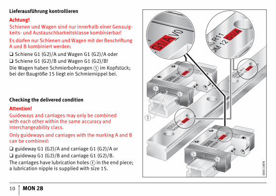
Lieferausführung kontrollieren
Achtung!Schienen und Wagen sind nur innerhalb einer Genauig-keits- und Austauschbarkeitsklasse kombinierbar!
Es dürfen nur Schienen und Wagen mit der Beschriftung A und B kombiniert werden:
❑ Schiene G1 (G2)/A und Wagen G1 (G2)/A oder❑ Schiene G1 (G2)/B und Wagen G1 (G2)/B!Die Wagen haben Schmierbohrungen � im Kopfstück;bei der Baugröße 15 liegt ein Schmiernippel bei.
Checking the delivered condition
Attention!Guideways and carriages may only be combinedwith each other within the same accuracy and interchangeability class.
Only guideways and carriages with the marking A and B can be combined:
❑ guideway G1 (G2)/A and carriage G1 (G2)/A or❑ guideway G1 (G2)/B and carriage G1 (G2)/B.The carriages have lubrication holes � in the end piece;a lubrication nipple is supplied with size 15.
R11 A_V0
KWEM 12 G1/ R11 A
TKDM 12 G1/
R11 A
TKDM 12 G1/
R11 A_V0
KWEM 12 G1/
_V0A
1
0001
3AFA

MON 28 11
Befestigungsschrauben und Anziehdrehmomente
Achtung!Einheiten nur mit vorgeschriebenen Schraubenbefestigen! Abmessung, Anzahl, Festigkeitsklasse,Anziehdrehmoment unbedingt einhalten,Tabelle Seite 12.
Fasteners and tightening torques
Attention!Units must only be located using the screws specified.It is absolutely essential that the correct size,quantity, grade and tightening torque are used,see table on page 12.
K1
G2
0001
3B00

12 MON 28
Befestigungsschrauben und Anziehdrehmomente
Fasteners and tightening torques
KWEM..(-W, -L, -C, -WL, -WC)1) G2DIN ISO 4 762-12.9
TKDM..(-W) K1DIN ISO 4 762-12.9
MANm
MANm
KWEM05 (-C) M2 0,6 TKDM05 M21) 0,6
KWEM05-W M2 0,6 TKDM05-W M21) 0,6
KWEM07 (-L, -C) M2 0,6 TKDM07 M2 0,6
KWEM07-W (-WL, -WC) M3 2,2 TKDM07-W M3 2,2
KWEM09 (-L, -C) M3 2,2 TKDM09 M3 2,2
KWEM09-W (-WL, -WC) M3 2,2 TKDM09-W M3 2,2
KWEM12 (-L, -C) M3 2,2 TKDM12 M3 2,2
KWEM12-W (-WL, -WC) M3 2,2 TKDM12-W M4 5
KWEM15 (-L, -C) M3 2,2 TKDM15 M3 2,2
KWEM15-W (-WL, -WC) M4 5 TKDM15-W M4 5
1) Schrauben zur Befestigung auf Anfrage lieferbar. 1) Screws for location available by agreement.

MON 28 13
Führungswagen demontieren
Achtung!Führungswagen � von der Führungsschiene immer auf eine Schutzschiene � schieben!
Dichtlippen am Führungswagen nicht beschädigen!
Die Schutzschiene im Führungswagen lassen!
❑ Schutzschiene vor die Führungsschiene setzenund den Wagen vorsichtig auf die Schutzschiene schieben.
Dismantling of carriages
Attention!The carriage � can only be moved off theguideway using the dummy guideway �.
Avoid damaging the seal lips on the carriage.
Leave the dummy guideway in the carriage.
❑ Locate the dummy guideway against the guideway and slide the carriage carefully onto the dummyguideway.
21
0001
3B01

14 MON 28
Führungswagen montieren
Achtung!Führungswagen � nur von Schutzschiene � aufdie Führungsschiene schieben!
Dichtlippen am Führungswagen nicht beschädigen!
❑ Schutzschiene mit Führungswagen vor die Führungs-schiene setzen und Führungswagen vorsichtig auf die Führungsschiene schieben.
Fitting of carriages
Attention!The carriage � can only be moved onto the guideway using the dummy guideway �.
Avoid damaging the seal lips on the carriage.
❑ Locate the dummy guideway with the carriage against the guideway and slide the carriage carefully onto the guideway.
2
1
0001
3B02

MON 28 15
Vormontierte Kugelumlaufeinheiten einbauen
Führungswagen vorher auf die Schiene schieben,Seite 14.❑ Schrauben � einsetzen und handfest anziehen.❑ Führungsschiene gegen die Anschlagseite drücken
(Pfeil).❑ Schrauben in der Reihenfolge nach
Anziehschema � anziehen, Tabelle, Seite 12.
Fitting of preassembled linear ball bearingand guideway assemblies
First slide the carriage onto the guideway, page 14.❑ Insert the screws � and tighten finger tight❑ Press the guideway against the locating side (arrow).❑ Tighten the screws in the sequence according to
the tightening scheme � and table, page 12.
1
0001
5671
1. 0,5 MA�
2. 1,0 MA�
MA
200
013B
04

16 MON 28
Vormontierte Kugelumlaufeinheiten einbauen
❑ Umlaufeinheit der Folgeseite � auf das Maschinen-bett setzen, Anschlagflächen seitenrichtig zuordnen.
❑ Schrauben � einsetzen und handfest anziehen.❑ Führungswagen � zu den Bohrungen des Maschinen-
schlittens ausrichten �, und Schlitten stoßfrei auf die Wagen setzen.
Fitting of preassembled linear ball bearingand guideway assemblies
❑ Locate the recirculating unit on the adjustment side � on the machine bed, ensuring that the locatingsurfaces are on the correct sides.
❑ Insert the screws � and tighten finger tight.❑ Align the carriages � with the locating holes in the
machine table � and place the table on the carriages without shocks.
4
4
3
3
12
0001
3B05

MON 28 17
Vormontierte Kugelumlaufeinheiten einbauen
❑ Schrauben � in die Bohrungen des Schlittenseinsetzen und handfest anziehen.
❑ Wagen � gegen die Anschlagflächen desSchlittens � drücken und Schrauben � anziehen; Tabelle, Seite 11.
❑ Schlitten � verfahren und dadurch die Führungs-schiene der Folgeseite ausrichten.
❑ Schrauben � in Führungsschiene in der Reihenfolge nach Anziehschema � anziehen, Tabelle, Seite 12.
Fitting of preassembled linear ball bearingand guideway assemblies
❑ Insert the screws � in the holes in the table andtighten finger tight.
❑ Press the carriage � against the locating surfacesof the table � and tighten the screws � according tothe table, page 11.
❑ Move the table � in order to align the guideway on the adjustment side.
❑ Tighten the screws � in the guideway in thesequence according to the tightening scheme �and table, page 12.
1
1
3
2
4
0001
3B06
MA
5
41. 0,5�MA
2. 1,0�MA
6
0001
5680
18 MON 28
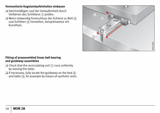
Vormontierte Kugelumlaufeinheiten einbauen
❑ Gleichmäßigen Lauf der Umlaufeinheit durchVerfahren des Schlittens � prüfen.
❑ Wenn notwendig Formschluss der Schiene zu Bett � und Schlitten � herstellen, beispielsweise mitKunstharz.
Fitting of preassembled linear ball bearingand guideway assemblies
❑ Check that the recirculating unit � runs uniformlyby moving the table.
❑ If necessary, fully locate the guideway on the bed � and table �, for example by means of synthetic resin.
13
2
0001
5681

MON 28 19
Schmierung
Geschmiert werden kann über Fettspritze � oder bei Baugröße 15 über beiliegenden Schmiernippel.
Die Fettspritze steht als Sonderzubehör zur Verfügung.
Achtung!Wagen beim Schmieren immer verfahren!
Mindesthub ist viermal Tragkörperlänge!
Lubrication
Lubrication can be carried out using the greasesyringe � or, in the case of size 15, the lubricationnipple supplied.
The grease syringe is available as a special accessory.
Attention!Always move the carriages during lubrication.
The minimum stroke is four times the lengthof the saddle plate.
1
0001
3B08
1
0001
3B09
20 MON 28
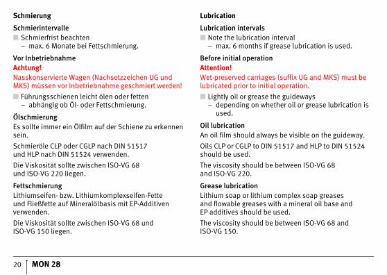
Schmierung
Schmierintervalle■ Schmierfrist beachten
– max. 6 Monate bei Fettschmierung.
Vor InbetriebnahmeAchtung!Nasskonservierte Wagen (Nachsetzzeichen UG und MKS) müssen vor Inbetriebnahme geschmiert werden!
■ Führungsschienen leicht ölen oder fetten– abhängig ob Öl- oder Fettschmierung.
ÖlschmierungEs sollte immer ein Ölfilm auf der Schiene zu erkennen sein.
Schmieröle CLP oder CGLP nach DIN 51517und HLP nach DIN 51524 verwenden.
Die Viskosität sollte zwischen ISO-VG 68und ISO-VG 220 liegen.
FettschmierungLithiumseifen- bzw. Lithiumkomplexseifen-Fetteund Fließfette auf Mineralölbasis mit EP-Additivenverwenden.
Die Viskosität sollte zwischen ISO-VG 68 undISO-VG 150 liegen.
Lubrication
Lubrication intervals■ Note the lubrication interval
– max. 6 months if grease lubrication is used.
Before initial operationAttention!Wet-preserved carriages (suffix UG and MKS) must be lubricated prior to initial operation.
■ Lightly oil or grease the guideways– depending on whether oil or grease lubrication is
used.
Oil lubricationAn oil film should always be visible on the guideway.
Oils CLP or CGLP to DIN 51517 and HLP to DIN 51524 should be used.
The viscosity should be between ISO-VG 68and ISO-VG 220.
Grease lubricationLithium soap or lithium complex soap greasesand flowable greases with a mineral oil base andEP additives should be used.
The viscosity should be between ISO-VG 68 andISO-VG 150.

MAT
NR
0280
2001
4-00
00 /
MO
N 2
8 /
D/G
B-D
/GB
/ 2
0090
9/ p
df o
nly
Schaeffler KG
Geschäftsbereich Lineartechnik
Berliner Straße 134
66424 Homburg (Saar)
Internet www.schaeffler.de
E-Mail [email protected]
In Deutschland:
Telefon 0180 5003872
Telefax 0180 5003873
Aus anderen Ländern:
Telefon +49 6841 701-0
Telefax +49 6841 701-2625
Schaeffler (UK) Ltd
Forge Lane, Minworth
Sutton Coldfield
West Midlands · B76 1AP
Telephone 0121 351 3833
Fax 0121 351 7686
E-mail [email protected]
Website www.schaeffler.co.uk
Nachdruck, auch auszugsweise, nur mit
unserer Genehmigung.
This publication or parts thereof may not
be reproduced without our permission.
© Schaeffler KG · 2009, September
MON 28 D/GB-D/GB