
ZVx - The Network Analyzer Family
62
1 ZVx - The Network Analyzer Family
-
Upload
lesley-love -
Category
Documents
-
view
50 -
download
2
description
ZVx - The Network Analyzer Family. S21. D. D. USB. LO. LSB. IF. S12. 1dB. D. D. 3. 3. S22. S11. S21. Power. frequency- converting. linear. ZVx- Overview. ZVRE, ZVR, ZVCE, ZVC, ZVM, ZVK: Functionalities. nonlinear. S-Parameter Group delay Impedance Admittance. - PowerPoint PPT Presentation
Transcript of ZVx - The Network Analyzer Family

1
ZVx - The Network Analyzer Family

2
ZVRE, ZVR, ZVCE, ZVC, ZVM, ZVK: Functionalities
linear nonlinear frequency-converting
• S-Parameter• Group delay• Impedance• Admittance
• Compression point• Interceptpoint IP2, IP3
• Mixer measurements• Any harmonics• Intermodulation• (Arbitrary frequency conv.)
ZVx- Overview
3 3
Power
S211dB
S21
S12
S11 S22
IF LOLSB USB

3
Test Sets & Frequency Ranges
ZVx- Overview
ZVC + ZVCE Active or PassiveTest Set
ZVR + ZVREActive Test Set
8 GHz4 GHz10 Hz 20 kHz9 kHz 300 kHz
ZVR + ZVREExternal Measurements
ZVR + ZVREPassive Test Set
20 GHz
ZVMActive Test Set
10MHz
ZVKActive Test Set
40 GHz

4
ZVR, ZVC, ZVM, ZVK: 4 receiver channels
• bidirectional
• standard calibration methods plus...
.... R&S calibration methods for test fixtures, on circuit boards
Distinguishing Features
ZVx- Overview
ZVRE, ZVCE: 3 receiver channels • bidirectional• standard calibration methods

5
ZVx- Test Sets
Basic Task of a NWA: Measurement of S-Parameters
SS1212
SS2121
SS1111 SS2222
b S a S a
b S a S a
1 11 1 12 2
2 21 1 22 2
bb11
aa11 bb22
aa22

6
ZVx- Test Sets
Principle of a 4-receiver NWA
Port 1
Port 2
Source
Meas. andDisplayUnit Test set
Meas. Channel b2
Ref. Channel a1
1
111 abS
1
221´ abS
2
222 abS
2
112 abS
b2b2
Meas. Channel b1
b1b1a1a1
Ref. Channel a2
a2a2
7
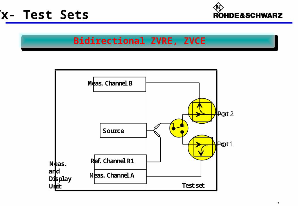
ZVx- Test Sets
Port 1
Port 2
Ref. Channel R1
Meas. Channel A
Source
Meas. Channel B
Meas. andDisplayUnit Test set
Bidirectional ZVRE, ZVCE

8
Bidirectional ZVR, ZVC
ZVx- Test Sets
Port 1
Port 2
Ref. Channel R1
Meas. Channel A
Source
Ref. Channel R2
Meas. Channel B
Meas. andDisplayUnit Test set
4 channel receiver. Calibration techniques for calibration in test fixture and on circuit board4 channel receiver. Calibration techniques for calibration in test fixture and on circuit board

9
Test Set of ZVR and ZVC: Options B21-B25, B6
ZVx- Test Sets with Options
PORT 1
PORT 2
Output a1
Input 1
Input b1
Source
MeasurementChannel A
Measurement Channel B
Reference. Channel R2
ZVR-B21
ZVR-B22
ZVR-B24 ZVR-B25
ZVR-B25
ZVR-B25
a1
b1
a2
b2
ReferenceChannel R1
ZVR-B6 ZVR-B23
Reference
channel ports

10
ZVx- Test Sets with Options
Test Set of ZVM, ZVK: Options B21-B24
ReferenceChannel a2
MeasurementChannel b2
PORT 2
INPUT b2ZVM(K)-B24
a2
b2
Generator
ZVM(K)-B23
DC Bias
ZVM(K)-B22
ZVM(K)-B21
PORT 1
ReferenceChannel a1
R1 CH. IN
MeasurementChannel b1 INPUT b1
b1
a1
b2
b1
DC Bias
R1 CH. OUT
R2 CH. OUT
R2 CH IN

11
External Test Set (*) for High Power Application
ZVx- Test Sets with Options
S22, S12Attenuator
Reference planes forPower and full two port calibration
DUT
PORT 2
INPUT b2
PORT 1
INPUT b1 S11, S21
Referencebackward
Amplifier
Amplifier Isolator
Isolator
Attenuator
Attenuator
Attenuator
Ref. A2 IN
Ref. A1 IN Referenceforeward
ReferenceChannel a2
MeasurementChannel b2
ZVM(K)-B24
a2
b2
Generator
ZVM(K)-B23
DC Bias
ZVM(K)-B22
ZVM(K)-B21
ReferenceChannel a1
MeasurementChannel b1
b1
a1
b2
b1
DC Bias
(*) Proposal for a test set. Components must be provided by customer.

12
Components inside the four channel instruments
ZVx - The Instruments in Detail
testset frontend converter measurementcontrol unit
front panel
AD
AD
AD
AD
LCD
CPU
synthesizer main processor, disk drives
PORT 1
interfaces
keys
referenceoscillator
signalgenerator
first secondlocal oscillator
PORT 2
a1
b1
b2
a2
13
ZVx - Specifications
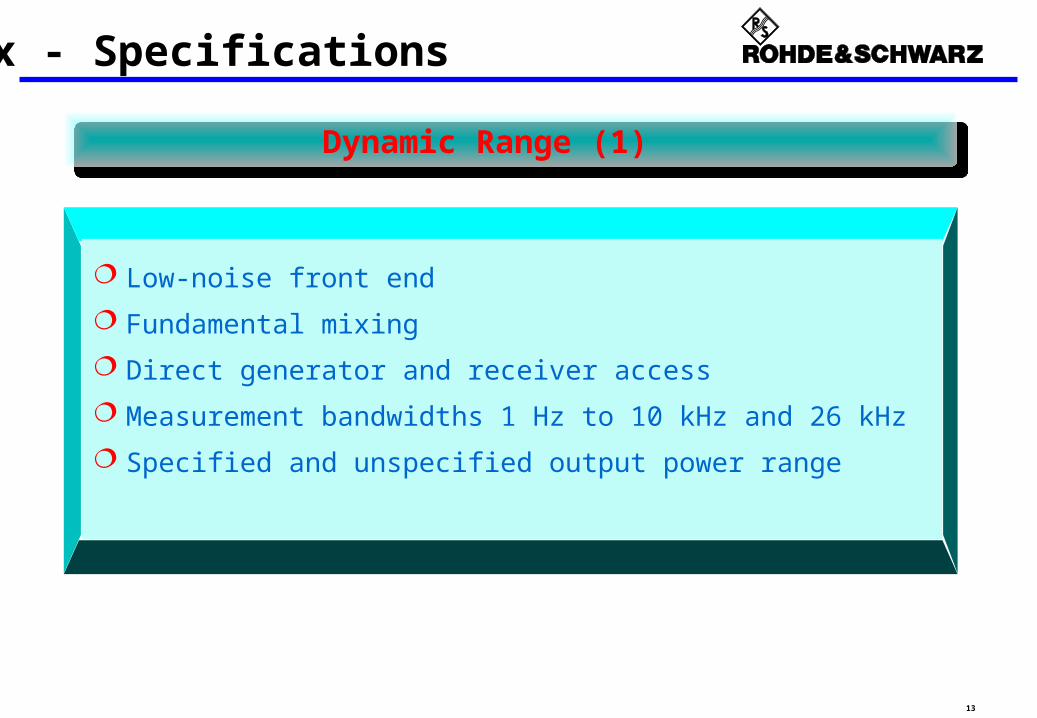
Dynamic Range (1)
Low-noise front end
Fundamental mixing
Direct generator and receiver access
Measurement bandwidths 1 Hz to 10 kHz and 26 kHz
Specified and unspecified output power range
14
ZVx - Specifications
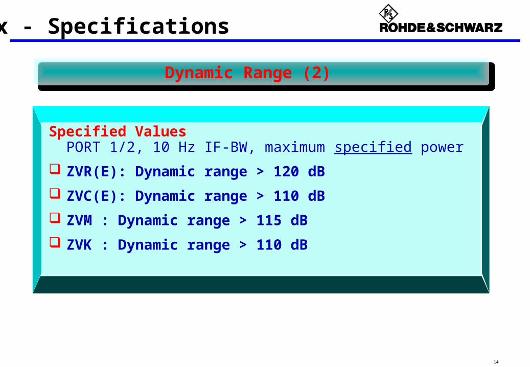
Dynamic Range (2)
Specified Values PORT 1/2, 10 Hz IF-BW, maximum specified power
ZVR(E): Dynamic range > 120 dB
ZVC(E): Dynamic range > 110 dB
ZVM : Dynamic range > 115 dB
ZVK : Dynamic range > 110 dB

15
ZVx - Specifications
Dynamic Range (3)
Maximum Values External Measurement / Input b2, 1 Hz IF-BW, maximum power (unspecified)
ZVR(E): Dynamic range > 140 dB
ZVC(E): Dynamic range > 135 dB (up to 6 GHz)
ZVM : Dynamic range > 140 dB (up to 18 GHz) > 130 dB (18 GHz to 20 GHz)
ZVK : Dynamic range > 135 dB

16
Dynamic Range (4): Filter Measurement with ZVR(E)
>120 dB with internal Test Set
>130 dB with Option "External Measurements" (direct generator - receiver access)
-130 dB
ZVx - Specifications
0 dB

17
2 GHz 18 GHz
20 dB/
-160 dB
0 dB
MAGdB CH1 ¯ -160 dB 0 dB
START 10 MHz STOP 20 GHz2 GHz/
EXT
FIL1 1 FIL1 1
S21
D1 -130 dB
Date: 4.OCT.00 18:46:08
2.4 GHz
20 dB/
-160 dB
0 dB
MAGdB CH1 ¯ -160 dB 0 dB
START 2 GHz STOP 2.44 GHz50 MHz/
CPL
EXT
FIL1 1 FIL1 1
S21
D1 -140 dB
Date: 5.OCT.00 16:38:04
- 140 dB- 140 dB - 130 dB- 130 dB16 GHz
ZVx - Specifications
Dynamic Range (5): Maximum Dynamic Range of ZVM
The highest dynamic range money can buy!
At ZVx, limit line defining the dynamic range is clearly above the noise floor,
not in the middle of the noise floor !

18
ZVx - Specifications
Dynamic Range (6): Maximum Dynamic Range of ZVK
5 G H z 3 5 G H z
2 0 d B /
- 1 6 0 d B
0 d B
M A Gd B C H 1 ¯ - 1 6 0 d B 0 d B
S T A R T 1 0 M H z S T O P 4 0 G H z5 G H z /
CPL
FIL10 10 FIL10 10
S 2 1 & M
1
23
4
1 : - 1 2 6 . 8 d B
5 0 0 M H z
2 : - 1 2 2 . 0 d B
8 G H z
3 : - 1 1 9 . 8 d B
1 6 G H z
4 : - 1 0 5 . 8 d B
2 8 G H z
Specified
• PORT1/2• 10 Hz IF BW• spec. Power
Maximum
• Input b2
• 1 Hz IF BW
• max. Power
110 dB105 dB
90 dB80 dB
20 dB/div
-120 dB
-140 dB
19
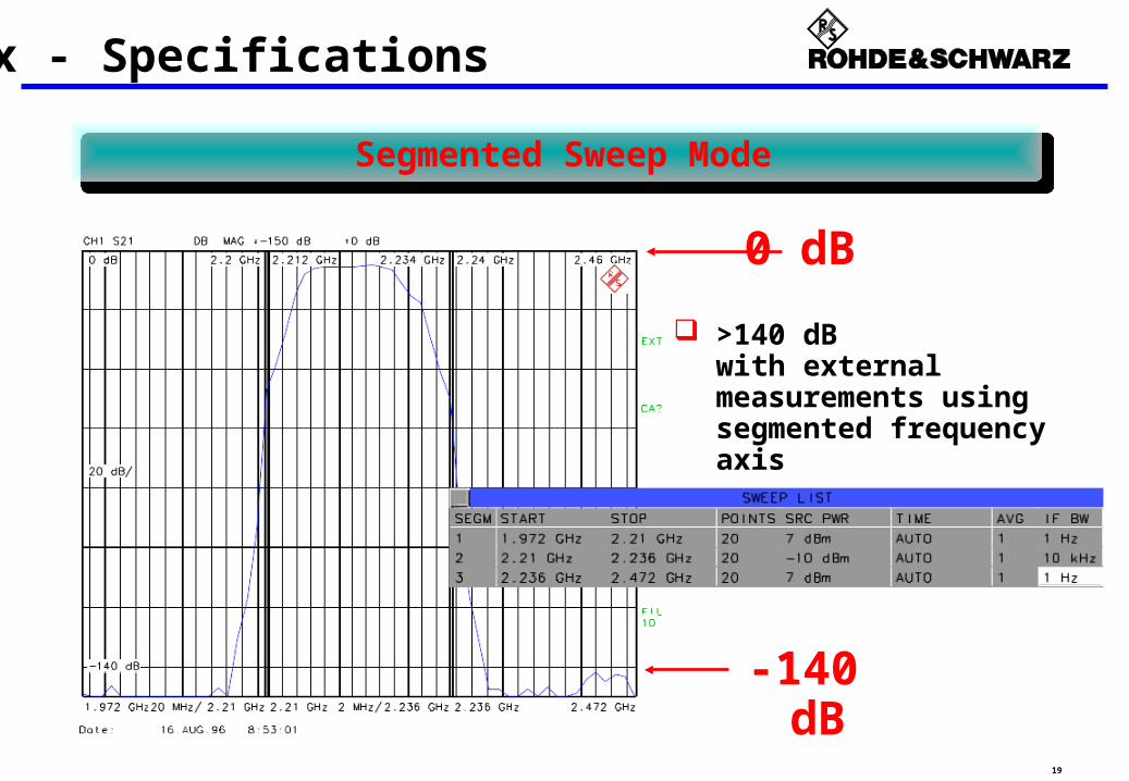
Segmented Sweep Mode
>140 dB with external measurements using segmented frequency axis
-140 dB
ZVx - Specifications
0 dB

20
Available power depends on... - Instrument- Option (External Measurement Option, Enhanced Power Opion, etc.)- Frequency range
Specified values for ZVR (examples):Standard 0 dBm at PORT1/2with ZVR-B25 +7 dBm at Output a1
With Option ZVR-B10 (Enhanced Output Power)Standard +13 dBm at PORT1/2with ZVR-B25 +20 dBm at Output a1
Specified values for ZVM: +2/+5 dBm
Specified values for ZVK: 0/-5 dBm
ZVx - Specifications
Output Power (1): Specified Values

21
Output power can be increased
above the specified level !
ZVx - Specifications
Maximum Output Power ZVM (2): Unspecified Values
Example: ZVM Maximum (unspecified) power ...
with setting “additional power” (*)
with standard setting
18 GHz
2 dB/
-4 dBm
16 dBm
MAGdB CH1 2 dB/ REF 0 dBm
START 10 MHz STOP 20 GHz2 GHz/
FIL1k 1k FIL1k 1k
CPL
b2&M
á 0 dBm
Date: 5.OCT.00 15:54:51
10 dBm
grid line
10 dBm
grid line
0 dBm
grid line
0 dBm
grid line
(*) Setting “Additional Power” avoids 4 dB attenuation
of a step attenuator, which is normally present
even if 0 dB attenuation is selected.
22
ZVx - Specifications
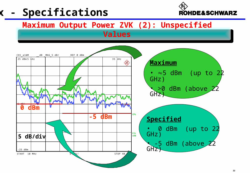
Maximum Output Power ZVK (2): Unspecified Values
Specified
• 0 dBm (up to 22 GHz)• -5 dBm (above 22 GHz)
5 GHz 35 GHz
5 dB/
-25 dBm
25 dBm
MAGdB CH1 5 dB/ REF 0 dBm
START 10 MHz STOP 40 GHz5 GHz/
FIL100100FIL100100
CPL
a1&M
á 0 dBm
5 dB/div
0 dBm
-5 dBm
Maximum
• 5 dBm (up to 22 GHz)
• >0 dBm (above 22 GHz)

23
Fast IEEE/IEC - bus data transfer and control
Enhanced throughput via LAN/Ethernet
Short measurement times per point
High sweep rate
Analog operational feeling
Increased system performance
ZVx - Specifications
Measurement & Transfer Speed (1)

24
ZVx - Specifications
Measurement & Transfer Speed (2)
IEC-bus data transfer of real and imaginary part(Time between sending of request and arrival of data at the PC)
Number of test points 51 201 401
ASCII 40 ms 90 ms 160 ms
IEEE-754-Floating-Point-Format(command data 64 bit,measurement data 32 bit)
10 ms 15 ms 25 ms

25
ZVx - Specifications
Measurement & Transfer Speed (3)
Measurement Times per PointIF-BW 10 kHz
ZVRLZVR(E)ZVC(E)
ZVM ZVK
Normalization < 0.24 ms < 0.5 ms < 0.7 ms
Full Two-PortCalibration
< 0.48 ms < 0.9 ms < 1.1 ms

26
Table of full two-port Calibration Procedures
ZVx - Specifications
TOM 5 inherent verification
Calibration procedure
Number of Calibration steps
Special feature
TRM
TNA
TRL
TOM-X
5 especially for test fixtures
4 high directivity
3 especially for test fixtures
5(9) eliminates crosstalk
TOSM
7 classical procedure
ZVRE and ZVCE just provide normalization and TOSM calibration techniques.

27
Capabilities for Enhanced Accuracy
Calibration techniques for all purposes- TOM calibration with inherent verification- TNA, TRM calibration for test fixtures / on circuit boards- TRL/LRL calibration for circuit boards and on wafers- TOM-X calibration for test setups with crosstalk
(De)Embedding functionality
Default / Factory calibration
Automatic two-port calibration AutoKal (up to 8 GHz)
Easy handling of calibration kit parameters
ZVx - Specifications

28
Integrated Pentium PC
Link to Ethernet & General IEC/IEEE-bus control
WINDOWS NT Operating System
PC-compatible formats for screen hardcopies
Connection to Ethernet with option FSE-B16
No external PC necessary - „Controller of its own“
Quick and easy documentation
Measurement and simulation in one instrument
ZVx - General Highlights
Open to PC and Ethernet

29
Efficiency & Operation
Huge display with 4-channel configuration
External PC monitor interface
Segmentation of frequency and magnitude axis
Numerous marker functions
Arbitrary zooming in all settings
Operation via hardkeys or mouse
Internal HDD for storage of data and settings
ZVx - General Highlights

30
Excellent technical data High speed
High sensitivity and dynamic range
High accuracy
Calibration Techniques
Wide frequency range
High versatility Frequency converting measurements
Harmonic measurements
Intercept- and compression point measurements
ZVx - Highlights (Survey)
Highlights of the ZVx instrument family

31
Software Options
ZVx - Options
ZVR-B2 Time Domain (*)Measurements of runtime & distance
Option Name Description
ZVR-B4
ZVR-B7
ZVR-B5
Frequ. Converting Measurements
Independent settings of generator and receiver
frequencies
Nonlinear Measurements
Measurement of n-dB compression point and SOI/TOI
Power CalibrationCalibration of all
generator and receiver
(*) Transputer module required
ZVR-K9 Virtual Embedding
NetworksVirtual integration of networks
Correction of existing networks

32
Hardware Options for ZVR(E), ZVC(E)
ZVx - Options
Option Name Description
ZVR-B6 Reference channel
portsDirect access to the reference channels
ZVR-B1
AutoKalAutomised
calibration procedure
ZVR-B25
ZVR-B21/22/23/24 Step AttenuatorsAttenuation of generator
and receiver level
External Measurements
Bypassing theSWR bridges
ZVR-B8(B14)
3/4 port adapterExtending Port 1 and/or
Port 2 to 2 ports
ZVR-B10 Increased Output
PowerIncreased Output Power
at Port 1 or Output a1

33
Hardware Options for ZVM, ZVK
ZVx - Options
Option Name Description
ZVM(K)-B21ZVM(K)-B22
Generator Step Attenuators
Attenuation of generator level
ZVM(K)-B23ZVM(K)-B24
Receiver Step Attenuators
• Attenuation of receiver level
• ZVM(K)-B23 includes Input b1
• ZVM(K)-B24 includes Input b2

34
Option ZVR-B1: AutoKal
ZVx - Options
Fundamental Calibration
TOM or TOSM
"Once a Year"
ZVR controlledautomatic calibrationin less than 20 seconds

35
Option ZVR-B2: Time Domain Measurements
ZVx - Options
Windows in frequency domain
Gating in time domain
Fast transformation time Online operation feeling
up to 2001 measurement points
Step response
Pulse response
36
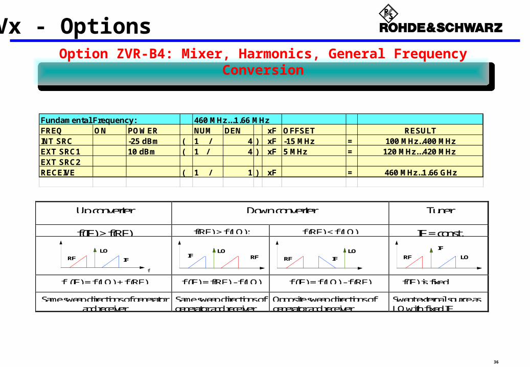
Option ZVR-B4: Mixer, Harmonics, General Frequency Conversion
ZVx - Options
Fundamental Frequency: 460 MHz...1.66 MHzFREQ ON POWER NUM DEN xF OFFSET RESULTINT SRC -25 dBm ( 1 / 4 ) xF -15 MHz = 100 MHz..400 MHzEXT SRC1 10 dBm ( 1 / 4 ) xF 5 MHz = 120 MHz...420 MHz EXT SRC2RECEIVE ( 1 / 1 ) xF = 460 MHz..1.66 GHz
Up converter Down converter Tuner
f(IF) > f(RF) f(RF) > f (LO): f (RF) < f (LO) IF = const.
RF
LO
IF
f
RFIFLO LO
IFRF RF LO
IF
f (IF) = f (LO) + f (RF) f (IF) = f(RF) - f (LO) f (IF) = f (LO) - f (RF) f(IF) is fixed
Same sweep directions of generatorand receiver
Same sweep directions ofgenerator and receiver
Opposite sweep directions ofgenerator and receiver
Swept external source asLO with fixed IF

37
ZVx - OptionsOption ZVR-B4: Mixer, Harmonics, General Frequency
Conversion
f
Pout
f1 f22f1-f2 2f2-f1 f
Swept intermodulation measurements
f
IF- RF LO IF+ 3LO-RF 3LO+RF
Triple swept mixer and spuries measurements
Intermodulation of amplifiers
Intermodulation of mixers
Any harmonics vs. Frequency
Any harmonics vs. power
Conversion of frontends, receivers(Internal LO & frequency conversion)

38
Option ZVR-B5: Non-linear Measurements
ZVx - Options
n-dB compression point vs. frequency Second/third order intercept point (SOI/TOI) vs. frequency
Pin [log]
Pout
[log]
11
3
1
TOI
f1, f2 IP3
n dB
Power towards amplifierP
ower
fro
m a
mpl
ifier
@ f0
n dB compression pointn dB compression point
ZVx performs power sweep(s) at each frequency point during a sweep.
Display of Compression point or SOI/TOI vs frequency
fff
P P
3*P3*P
fIP3- f1 f2 IP3+
P [log]

39
Option ZVR-B6: Reference channel port (1/3 )
ZVx - Options
PORT 1
PORT 2
Output a1
Input 1
Input b1
Source
MeasurementChannel A
Measurement Channel B
Reference. Channel R2
a1
b1
a2
b2
ReferenceChannel R1
ZVR-B6 Reference
channel ports
Path from source to the Ref-Channel interruptedusing mechanical switches
Signal for the Reference Channel can be fed from outside of the NWA
Option just for ZVR(E), ZVC(E)(Access to both reference channels standard at ZVM, ZVK via jumpers at the front panel)

40
Option ZVR-B6: Reference channel port (2/3)
ZVx - Options
Po
wer
sp
litt
er
Input b1
Source
MeasurementChannel A
a1
b1
ReferenceChannel R1
ZVR-B6
DUT
Pre-amplifier
ZVR(E), ZVC(E)
ZVR-B6 Application example 1:
Example: Pre-amplifier to provide high power for the DUT
• Getting the „real“ reference signal
• Correction for non-linearities and (temperature) drift of the pre-amplifier

41
Option ZVR-B6: Reference channel port (3/3 )
ZVx - Options
PORT 2
Output a1
Input 1
Input b1
a1
b1
a2
b2
External Signal Generator
(LO)
f0
f0
Reference channel
Source f0
Measurement channel
f0
fconv
fLOfLO
fconv
fconv Measurement at
converted frequency fconv
DUT(frequency converting)Reference mixer
f0 fconv
ZVR-B6 Application example 2:
External ref. mixer:
• Equal frequencies in measurement and ref-channel
• „Comparison“ of equal frequencies allows phase and group delay measurements

42
Option ZVR-B7: Power Calibration
ZVx - Options
Po rt 1
P ort 2
Ref. Channel R1
M eas. Channel A
Source
Ref. Channel R2
M eas. Channel B
M eas. andDisplayUnit Test set
Generator Receiver
Power meter
IEC II
ZVR
Power calibration of the internal generator
Power calibration of the receiver
Generator (cal.) ReceiverZVR
Accuracy: up to 0.1 dB or better

43
Option ZVR-B8: 3-Port Adapter
ZVx - Options
CH 1
CH 2
CH 3
CH 4
ZVR
ZVR-B8
Port 1 Port 2
TX
RX
ANT
1
2
3
multiport adapter
DUT example:
antenna diplexer Automatic Control by ZVR
Switching time 10 s
Measurement of 7 (from 9)S-params of a 3-port devicewithout rewiring
CH1 & CH3 show Port 1CH2 & CH4 show Port 2

44
Option ZVR-B14: 4-Port Adapter
ZVx - Options
PORT2PORT1
ZVR-B144-Port Adapter .02
CH 1
CH 2
CH 3
CH 4
ZVR
DUT
DUT
1 2 3 4
CH 1
CH 2
CH 3
CH 4
ZVR
ZVR-B144-Port Adapter .03
DUT
PORT1 PORT2
1 2 3 4

45
Option ZVR-K9: (De)Embedding (Part 1/3)
ZVx - Options
Simulation of virtual networks
Elimination of real existing networks
Simulation of Matching Networks with SAW filters
Identical matching at each production place

46
Option ZVR-K9: (De)Embedding (Part 2/3)
ZVx - Options
2 431
TN2TN1 DUT
DUT1 2 3 4
Integration of 2-port solutions
Embedding of 4-port data
Integration of 1-port solutions

47
Option ZVR-K9: (De)Embedding (Part 3/3)
ZVx - Options
ideal NWA
1'
E1 V1-1 DUT
1
"modified" error two port
neutral Network
V-1 ° V =1
1''
1
V1

48
Option ZVR-B10: Enhanced Output Power
ZVx - Options
Internal Pre-Amplifier
Enhanced power in foreward direction
Option for ZVR(E), ZVC(E)
Maximum power depends on model: Different for ZVR(E) and ZVC(E)
Maximum power depends on directive component: Different maximum power for ZVC(E) with couplers or ZVC(E) with bribges
Maximum power: Output a1 at ZVR: + 20 dBm

49
Frequency converting and nonlinear Measurements
Characterisation of frequency converting devices
Characterisation of nonlinear parameters
Generator / receiver with arbitrary frequency offset
Up to two external generators controlled by ZVx
Measurement of mixers, frequency multipliers and amplifiers, frontends etc
Determination of compression and intercept point
Display of compression and IP2/3 versus frequency
ZVx - Amplifier & Mixer Measurements

50
Example 1: Intermodulation Measurements
ZVx - Amplifier & Mixer Measurements
f
f
ZVM
IEEE/IEC-Bus II
Freq.REF IN
Ext. Source
f1
f2
ZAPDJ-2
ZJL-3GPin
Pout
ff1 f2
f1 f22f1-f2 2f2-f1 f
Port 1 Port2
No external filters required
No limitations of frequency ranges and offsets
All settings controlled by the ZVM

51
Example 1: Intermodulation Measurements (cont.)
ZVx - Amplifier & Mixer Measurements
Settings for carrier f1
Settings for carrier f2

52
Example 1: Intermodulation Measurements (cont.)
ZVx - Amplifier & Mixer Measurements
Settings for measuring the lower IP3 product 2f1-f2.
Settings for measuring the upper IP3 product 2f2-f1.

53
Example 1: Intermodulation Measurements (cont.)
ZVx - Amplifier & Mixer Measurements
590 MHz
5 dB/
-30 dBm
20 dBm
590 MHz
5 dB/
-30 dBm
20 dBm
590 MHz
5 dB/
-30 dBm
20 dBm
590 MHz
5 dB/
-30 dBm
20 dBm
b2
ARB
FIL10k10kFIL10k10k
MAG
MAGb2
MAGb2
MAGb2
10 MHz/ 600 MHz500 MHz
REF 0 dBm5 dB/
10 MHz/ 600 MHz500 MHz
REF 0 dBm5 dB/
10 MHz/ 600 MHz500 MHz
REF 0 dBm5 dB/
10 MHz/ 600 MHz500 MHz
REF 0 dBm5 dB/
á 0 dBm
á 0 dBm
á 0 dBm
á 0 dBm
Date: 3.DEC.99 16:16:47
lower IP3 product2f1-f2
upper IP3 product2f2-f1
carrier f1
carrier f2

54
Example 2: Mixer Measurement
ZVx - Amplifier & Mixer Measurements
IEEE / IEC-Bus II
ref. Freq.
ZVM
PORT 1
PORT 2
Source
RF
LO
IF
ZFM-4
R
I
L

55
Example 2: Mixer Measurement (cont.)
ZVx - Amplifier & Mixer Measurements
ARBITRARY SYSTEM FREQUENCIES
BASE FREQUENCY: 100MHz ...400MHz
ON POWER (NUM / DEN) xB + OFFSET RESULT
INT SRC / 0 dBm (1 / 1) xB 100MHz..400MHz
EXT SRC1 / 7 dBm (1 / 1) xB +20MHz 120MHz..420MHz
EXT SRC2
RECEIVER / (4 / 1) xB +60MHz 460MHz..1.66GHz
STIMULUS AXIS: RECEIVER 460MHz..1.66GHz
B = RF = 100 MHz ... 400 MHz
f(LO) = RF + 20 MHz
f(Rec) = 3*LO +RF = 3*(RF + 20 MHz) + RF = 4*RF + 20 MHz
Scaling for x-axis
20 100 120 220 260 400 420 460 820 860 1660 f / MHz
Offset = 20 MHz
IF- RF LO IF+
3LO-RF 3LO+RF

56
Example 3: Amplifier Measurements
ZVx - Amplifier & Mixer Measurements
ZVR
PORT 1 PORT 2

57
Example 3: Amplifier Measurements (cont.)
ZVx - Amplifier & Mixer Measurements
S21 small signal parameter
S21 versus power
@ 1GHz
second harmonic versus power
@ 1GHz
1 dB compr. point versus frequency
Examples for measurement quantities

58
Example 4: Hot-S-Parameters
ZVx - Amplifier & Mixer Measurements
2 swept tones f1, f2 are fed to the amplifier
Constant, narrow offset f = |f2 - f1|
Power of signal f2:- Constant at high power level- Defines the operating point
Power of signal f1:- Constant at small signal range- Measurement of S21
(Both generator and receiver of ZVx at frequency f1 !)
Ext. Source
ZVx
IEEE / IEC-Bus II
Freq. ref REF IN
PORT 1 PORT 2
combiner DUT (amplifier)
f1
f2
f1
f2
Po
wer
f2
f1
f
f
59
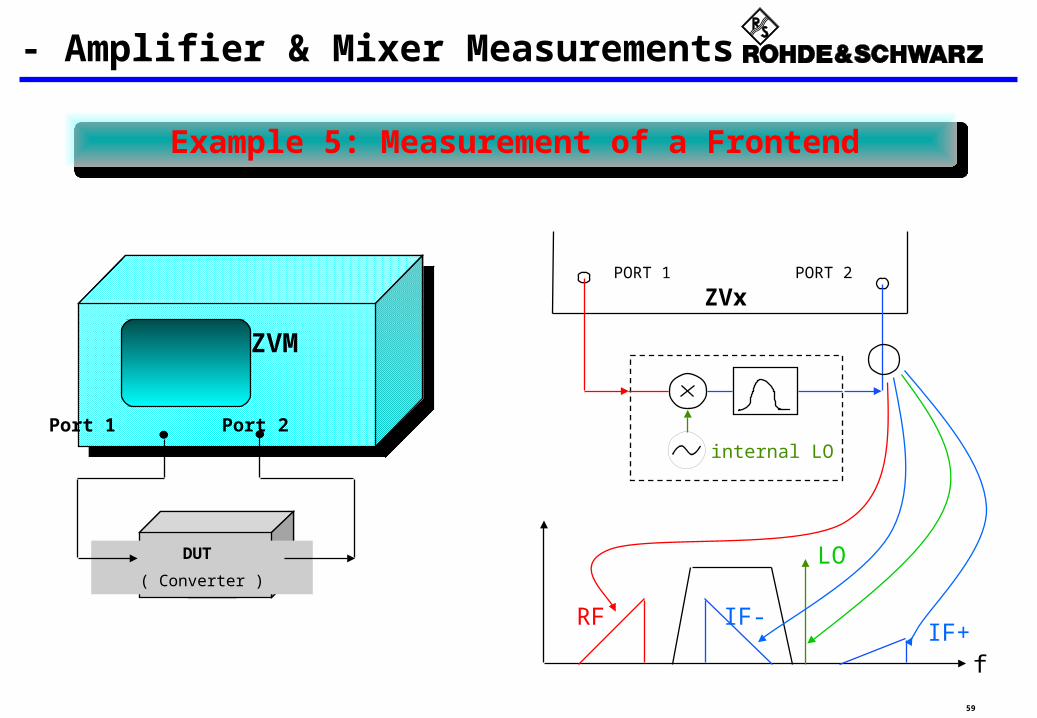
Example 5: Measurement of a Frontend
ZVR
Port 2
DUT
( Converter )
ZVM
Port 1 Port 2
ZVx - Amplifier & Mixer Measurements
internal LO
PORT 2PORT 1
f
RF IF-IF+
LO
ZVx

60
Example 5: Measurement of a Frontend (cont.)
ZVx - Amplifier & Mixer Measurements
Conversion loss IF- (wanted sideband)
Conversion loss IF+ (unwanted sideband)
LO power
(used also for LO freq. detection)
Return loss
61
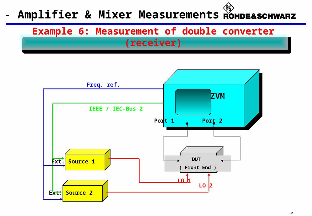
Example 6: Measurement of double converter (receiver)
DUT
( Front End )
Ext. Source 2
ZVM
IEEE / IEC-Bus 2
Freq. ref.
LO 1LO 2
Ext. Source 1
Port 1 Port 2
ZVx - Amplifier & Mixer Measurements

62
Example 6: Measurement of double converter (receiver)
ZVx - Amplifier & Mixer Measurements