ZSC31010 / ZSC31015 / ZSSC3015 ZACwire™ SSC Modular ...
30
ZSC31010 / ZSC31015 / ZSSC3015 ZACwire™ SSC Modular Evaluation Kit Description © 2016 Integrated Device Technology, Inc. 1 April 26, 2016 Restrictions: IDT’s ZACwire™ SSC Modular Evaluation Kit (SSC Evaluation Kit) hardware and software are designed for evaluation of the ZSC31010, ZSC31015, or ZSSC3015; laboratory setup; and module development only. The ZACwire™ SSC Modular Evaluation Kit hardware and software must not be used for module production and production test setups. IDT shall not be liable for any damages arising out of defects resulting from (i) delivered hard and software (ii) non-observance of instructions contained in this manual, or (iii) misuse, abuse, use under abnormal conditions or alteration by anyone other than IDT. To the extent permitted by law, IDT hereby expressly disclaims and User expressly waives any and all warranties, whether express, implied, or statutory, including, without limitation, implied warranties of merchantability and of fitness for a particular purpose, statutory warranty of non-infringement and any other warranty that may arise by reason of usage of trade, custom or course of dealing. Contents 1 Kit Contents ......................................................................................................................................................... 4 2 SSC Evaluation Board......................................................................................................................................... 5 2.1. Overview ....................................................................................................................................................... 5 2.2. Connections to the DUT ............................................................................................................................... 6 2.3. Power Supply to the Board ........................................................................................................................... 6 2.4. Reset Switch ................................................................................................................................................. 6 3 Software Installation and Setup........................................................................................................................... 6 3.1. Installing the ZACwire™ SSC Evaluation Kit Software ................................................................................ 6 3.2. Installing the USB Drivers............................................................................................................................. 7 3.3. HW Type / Select Product / Find COM / Initialize HW Button ...................................................................... 7 4 SSC Evaluation Kit Software ............................................................................................................................... 9 4.1. Software Overview ....................................................................................................................................... 9 4.1.1. Bridge and Temperature Display .......................................................................................................... 9 4.1.2. Data Logging Section .......................................................................................................................... 10 4.1.3. EEPROM Section ................................................................................................................................ 10 4.1.4. Command Interface Section................................................................................................................ 11 4.1.5. Response Field ................................................................................................................................... 11 4.1.6. Command/Subcommand/Data Fields ................................................................................................. 12 4.1.7. Send Button......................................................................................................................................... 12 4.1.8. Start CM Button ................................................................................................................................... 12 4.1.9. Start NOM Button ................................................................................................................................ 12 4.1.10. Start RM Button ................................................................................................................................... 12
Transcript of ZSC31010 / ZSC31015 / ZSSC3015 ZACwire™ SSC Modular ...

ZSC31010 / ZSC31015 / ZSSC3015 ZACwire™ SSC Modular Evaluation Kit Description
© 2016 Integrated Device Technology, Inc. 1 April 26, 2016
Restrictions: IDT’s ZACwire™ SSC Modular Evaluation Kit (SSC Evaluation Kit) hardware and software are designed for evaluation of the ZSC31010, ZSC31015, or ZSSC3015; laboratory setup; and module development only. The ZACwire™ SSC Modular Evaluation Kit hardware and software must not be used for module production and production test setups. IDT shall not be liable for any damages arising out of defects resulting from (i) delivered hard and software (ii) non-observance of instructions contained in this manual, or (iii) misuse, abuse, use under abnormal conditions or alteration by anyone other than IDT. To the extent permitted by law, IDT hereby expressly disclaims and User expressly waives any and all warranties, whether express, implied, or statutory, including, without limitation, implied warranties of merchantability and of fitness for a particular purpose, statutory warranty of non-infringement and any other warranty that may arise by reason of usage of trade, custom or course of dealing.
Contents 1 Kit Contents ......................................................................................................................................................... 4
2 SSC Evaluation Board ......................................................................................................................................... 5 2.1. Overview ....................................................................................................................................................... 5 2.2. Connections to the DUT ............................................................................................................................... 6 2.3. Power Supply to the Board ........................................................................................................................... 6 2.4. Reset Switch ................................................................................................................................................. 6
3 Software Installation and Setup........................................................................................................................... 6 3.1. Installing the ZACwire™ SSC Evaluation Kit Software ................................................................................ 6 3.2. Installing the USB Drivers ............................................................................................................................. 7 3.3. HW Type / Select Product / Find COM / Initialize HW Button ...................................................................... 7
4 SSC Evaluation Kit Software ............................................................................................................................... 9 4.1. Software Overview ....................................................................................................................................... 9
4.1.1. Bridge and Temperature Display .......................................................................................................... 9 4.1.2. Data Logging Section .......................................................................................................................... 10 4.1.3. EEPROM Section ................................................................................................................................ 10 4.1.4. Command Interface Section ................................................................................................................ 11 4.1.5. Response Field ................................................................................................................................... 11 4.1.6. Command/Subcommand/Data Fields ................................................................................................. 12 4.1.7. Send Button ......................................................................................................................................... 12 4.1.8. Start CM Button ................................................................................................................................... 12 4.1.9. Start NOM Button ................................................................................................................................ 12 4.1.10. Start RM Button ................................................................................................................................... 12

ZSC31010 / ZSC31015 / ZSSC3015 ZACwire™ SSC Modular Evaluation Kit Description
© 2016 Integrated Device Technology, Inc. 2 April 26, 2016
4.1.11. Normal Mode Section .......................................................................................................................... 12 4.1.12. Output Mode Section........................................................................................................................... 13 4.1.13. Adjustment of the Analog Pre-Amp Gain and the Analog ADC Offset Modes.................................... 13 4.1.14. Calibration Button ................................................................................................................................ 14
4.2. Calibration Sequence ................................................................................................................................. 15 4.2.1. Step 1 – Assigning a Unique Identification (ASIC ID Section) ............................................................ 16 4.2.2. Step 2 – Data Collection ..................................................................................................................... 17 4.2.3. Step 3 – Calculate & Write Coefficients .............................................................................................. 18
4.3. Section Output Range Checking ................................................................................................................ 18
5 Dry Run Calibration ........................................................................................................................................... 19
6 Calculation of Calibration Coefficients Off-line .................................................................................................. 21
7 SSC Evaluation Kit Software with the IDT SSC Terminal ................................................................................. 24 7.1. Protocol ....................................................................................................................................................... 24 7.2. IDT SSC Terminal ...................................................................................................................................... 24
8 Related Documents ........................................................................................................................................... 26
9 Definitions of Acronyms ..................................................................................................................................... 27
10 Document Revision History ............................................................................................................................... 27
Appendix A: Schematic ZSC31010 SSC Evaluation Board ..................................................................................... 29

ZSC31010 / ZSC31015 / ZSSC3015 ZACwire™ SSC Modular Evaluation Kit Description
© 2016 Integrated Device Technology, Inc. 3 April 26, 2016
List of Figures Figure 1.1 ZACwire™ SSC Modular Evaluation Kit ................................................................................................ 4 Figure 2.1 SSC Evaluation Board Overview ........................................................................................................... 5 Figure 3.1 Hardware Type Selection Example for ZSC31010 ................................................................................ 8 Figure 3.2 Product and COM Port Selection Example for ZSC31010 .................................................................... 8 Figure 4.1 Bridge and Temperature Display and Data Logging Screen (ZSC31010 Coefficients Shown) .......... 10 Figure 4.2 EEPROM Section Example (ZSC31010 Coefficients Shown) ............................................................ 11 Figure 4.3 Calibration Window Example (ZSC31010 Coefficients Shown) .......................................................... 15 Figure 4.4 ASIC ID Section for Initialization, Identification, and Adjustment (ZSC31010 Settings Shown) ......... 16 Figure 4.5 Section Output Range Checking ......................................................................................................... 18 Figure 5.1 Example for a 2-Point Calibration (ZSC31010 Coefficients Shown) ................................................... 20 Figure 6.1 Fields for Manually Entering Target and Raw Values (ZSC31010 Coefficients Shown)..................... 23 Figure 7.1 SSC Terminal Example ....................................................................................................................... 25
List of Tables Table 4.1 Output Mode Options ........................................................................................................................... 13 Table 4.2 Programmable Pre-amp Gain Settings ................................................................................................ 14 Table 6.1 Example Spreadsheet Data ................................................................................................................. 22 Table 7.1 SSC Terminal Command Format ........................................................................................................ 24

ZSC31010 / ZSC31015 / ZSSC3015 ZACwire™ SSC Modular Evaluation Kit Description
© 2016 Integrated Device Technology, Inc. 4 April 26, 2016
Sensor Replacement Board
ZSC31010 SSC Evaluation Board used for ZSC31010, ZSC31015, and ZSC3015 (SSC Evaluation Board)
USB Connector
SSC Communication Board (CB)
1 Kit Contents • SSC Communication Board Ver. X.x (CB) and cable (for further information on the CB, see SSC_Communication
Board_VX-x_DataSheet_ Rev_X_x.pdf, which is available at www.IDT.com; see section 8 for details)
• ZSC31010 SSC Evaluation Board V1.0, which is used for the ZSC31010, ZSC31015, and ZSSC3015.
• SSC Sensor Replacement Board (SRB) (SSC Sensor Dummy V2.0)
• Five samples of the ZSC31010, ZSC31015, or ZSSC3015 (SOP8 150mil)
• SSC Test Board V1.0
Note: The ZACwire™ SSC Evaluation Kit Software is downloaded from IDT’s website at www.IDT.com as described in section 3.1.
Figure 1.1 ZACwire™ SSC Modular Evaluation Kit
The ZACwire™ SSC Modular Evaluation Kit (SSC Evaluation Kit) provides the hardware needed for communication and calibration of the ZSC31010, ZSC31015, or ZSSC3015 sensor signal conditioning (SSC) ICs. A PC can communicate with the ZSC31010 SSC Evaluation Board (used for all three products) via the SSC Communication Board (CB) through a USB connection. The software should function on any Windows® 2000/XP/ Vista / Windows® 7/Windows® 8 system after the installation of a USB driver.

ZSC31010 / ZSC31015 / ZSSC3015 ZACwire™ SSC Modular Evaluation Kit Description
© 2016 Integrated Device Technology, Inc. 5 April 26, 2016
VSS VSS VSS VSS
Bsink VBP Ext. Temp* VBN
Bsink VBP Ext. Temp* VBN
VDD VDD VDD VDD
VDD VDD VDD VDD
VSS OUT VDD Vgate
VSS OUT VDD Vgate
VSS VSS VSS VSS
K4 Jumper
Bridge GND to BSink
Bridge GND to VSS
KL1 Connector to External Bridge
Resistors for Board Identification
Pin 1 on DUT
K1 Connector to the SSC CB
Jumper K3
Without JFET (KS5V)
With JFET (KS12V)
K2 Connector to SRB
2 SSC Evaluation Board
2.1. Overview The main purpose of the SSC Evaluation Kit is to perform communication between the user’s PC and the ZSC31010, ZSC31015, or ZSSC3015 (referred to as the DUT). The PC sends commands and data via the USB port on the CB (virtual COM port). The microcontroller on the CB interprets these commands and relays them to the DUT in the ZACwireTM format (connector K1, Pin 39; see Figure 2.1). The microcontroller will also forward any data bytes from the DUT back to the PC via the USB connection. These bytes can be bridge and temperature readings to be displayed by the ZACwire™ SSC Evaluation Kit software or raw ADC readings used during calibration or EEPROM content bytes.
Figure 2.1 SSC Evaluation Board Overview
*Ext. Temp pin only available on ZSC31015 and ZSC3015. This pin is not connected (nc) for the ZSC31010.

ZSC31010 / ZSC31015 / ZSSC3015 ZACwire™ SSC Modular Evaluation Kit Description
© 2016 Integrated Device Technology, Inc. 6 April 26, 2016
2.2. Connections to the DUT The SSC Evaluation Board has an SOP-8 socket location for inserting the DUT.
Using the KS5V signal for the power supply, the ZACwireTM signal (OWI), and the ground (GND) connection on connector K4 on the CB, the board can be used for in-circuit programming of the DUT in the user’s calibration fixture. Important: In this case (without the SSC Evaluation Board) a 3.3kΩ pull-up resistor must be added to the CB between OWI and Tr D2 or between OWI and KS5V (if connected).
NOTE: Only one ASIC connection option can be used at a time.
2.3. Power Supply to the Board The K1 connector to the CB provides the power supply from the CB’s USB port to the SSC Evaluation Board. All functions of the board are operative down to 2.7V. The board has a red LED labeled D1 which lights if the board has power.
2.4. Reset Switch During operation, use the push button on the CB to reset communications. Note: If the communication port is open, the hardware must be re-initialized using the “Initialize HW” button in the software (see Figure 4.1) following a reset.
3 Software Installation and Setup
3.1. Installing the ZACwire™ SSC Evaluation Kit Software The ZACwire™ SSC Modular Evaluation Kit does not include the software, which must be downloaded from the IDT website (www.IDT.com) to ensure receiving the latest release. To download the software, navigate to the product page as follows:
• ZSC31010: www.IDT.com/ZSC31010• ZSC31015: www.IDT.com/ZSC31015• ZSSC3015: www.IDT.com/ZSSC3015
On the product page, under the heading “General Documents and Supporting Materials,” click on the link titled “ZACwire™ Evaluation Software Rev.X” (where X is the current revision) and follow the dialog instructions as needed to download the zip file for the software.
Open the zip file and extract the ZACwireSSC_Setup_vX.exe file.

ZSC31010 / ZSC31015 / ZSSC3015 ZACwire™ SSC Modular Evaluation Kit Description
© 2016 Integrated Device Technology, Inc. 7 April 26, 2016
To install the ZACwire™ SSC Evaluation Kit software on the user’s PC hard drive, double-click on the downloaded ZACwireSSC_Setup_vX.exe file. Respond to the dialog box to select the installation directory, and the software will complete the installation, which results in a program shortcut on the desktop of the PC.
Note: When the software is activated for the first time, the kit type (“HW type”) and product type (ZSC31010, ZSC31015, or ZSSC3015) must be selected and the COM port must be entered as described in section 3.3.
3.2. Installing the USB Drivers The SSC Evaluation Kit requires installation of two USB drivers. To install the drivers, the user’s system must meet these requirements:
• x86-compatible PC• 32 MB RAM• Hard drive with 20MB free space• USB port• Windows® 2000/XP/ Vista / Windows® 7 / Windows® 8
The two required driver files can be downloaded from www.IDT.com/SSC-COMM-BD. Click on the link titled “SSC CB USB Driver Rev. X” (where X is the current revision) and follow the dialog instructions as needed to download the zip file for the drivers and extract the files. These drivers will make the PC’s USB port appear as a virtual COM port (typically COM3 or COM4 on most computers). The SSC Evaluation Kit software accesses the SSC Evaluation Board through the CB as if it were a COM (RS232) port. These drivers will not affect the operation of any other USB peripherals.
Refer to SSC_AN_CommunicationBoard_Driver_Installation_Rev_X_x.pdf for instructions on installing these two drivers and for determining the virtual COM port for the SSC Evaluation Kit, which is needed for setting up the kit. This document is available under the “General Documents and Supporting Materials” heading.
3.3. HW Type / Select Product / Find COM / Initialize HW Button After installing the software and the USB drivers, activate the software. On the “Setup” pull-down menu, select “HW Type” and then “SSC Eval Kit” as shown in Figure 3.1.
Then click on “Select Product” under the “Setup” menu and select ZSC31010, ZSC31015, or ZSSC3015 as shown in Figure 3.2. The title bar of the screen will change to reflect the product selection.
Next, enter the correct virtual COM port setting to use for the PC ⇔ SSC Evaluation Board communication via USB as shown in Figure 3.2. If the correct setting is unknown, click the “Find COM” button under the “Setup” menu and accept the port found or continue searching until the COM port setting is correct. Click on “Initialize HW” to set up the SSC hardware for operation.
If the Initialization was successful, the status window on the right side of the screen will say “Initializing HW… OK.” If communication fails, an error message detailing the reason for failure will be displayed. For a full list of all communication-related error messages, see the “Error-Code” tab in the spreadsheet SSC_CommunicationBoard_ CommandSyntax_Rev_X_x.xls (see section 7.2).

ZSC31010 / ZSC31015 / ZSSC3015 ZACwire™ SSC Modular Evaluation Kit Description
© 2016 Integrated Device Technology, Inc. 8 April 26, 2016
Select “SSC Eval Kit” for the HW type under the “Setup” menu.
Communication status appears here depending on port setup.
If the COM port is already known, select it here and click “Open.”
Selected product and hardware type are shown in title bar.
To find a COM port, click here and respond to resulting dialog box until oper-ational port is identified.
Click “Select Product” and either ZSC31010, ZSC31015, or ZSSC3015.
Figure 3.1 Hardware Type Selection Example for ZSC31010
Figure 3.2 Product and COM Port Selection Example for ZSC31010

ZSC31010 / ZSC31015 / ZSSC3015 ZACwire™ SSC Modular Evaluation Kit Description
© 2016 Integrated Device Technology, Inc. 9 April 26, 2016
4 SSC Evaluation Kit Software
4.1. Software Overview The SSC Evaluation Kit software provided with the SSC Evaluation Kit is intended for demonstration purposes and calibration of single units. IDT can provide the user with algorithms and assistance in developing their full production calibration software. The default installation folder is C:\Program Files\ZMDI\ZACwire SSC Kit\. Four types of text files support the software user. These files are saved in the My Documents folder under ZMDI\ZSC31010, ZMDI\ZSC31015, or ZMDI\ZSSC3015 depending on the “Select Product” setting described in section 3.3.
• When the software is activated, a CommLog.txt file is saved. This file is a log of the communication to theIC during the software session and can be saved after closing the software by renaming the file. Other-wise, it would be overwritten the next time the software is opened.
• In Command Mode (CM), the user can save/load the EEPROM contents from a user-selected *.eep file tothe EEPROM.
• In Normal Operation Mode (NOM), the user can log bridge and temperature readings to a user-selectedfile.
• The calibration is documented in the CalibrationLog_DDMMMYYYY.txt file.
4.1.1. Bridge and Temperature Display The software displays two large readout windows for temperature and bridge values as shown in Figure 4.1. The temperature reading is the DUT temperature in oC. The bridge reading is in %. Calibration determines the relation-ship of the % reading to the value the bridge is measuring. The IC is designed to be a generic resistive bridge sensor signal conditioner, but for the following calibration example, assume it is connected to a pressure bridge. If the unit is calibrated to read pressure with 50kPa reading as 100% and 10kPa reading as 0%, then the span of pressure readings would be 40kPa. Half that span (20kPa) plus the set zero point (10kPa) should be the 50% point. After calibration, if the chamber is set to 30kPa, the RBic™ should give a 50% reading.
These readout windows only display temperature and bridge readings if the IC is programmed in digital output configuration. There are two digital output configurations:
• Transmission of bridge readings and temperature
• Transmission of only bridge readings (no temperature)
Temperature is not displayed unless the IC is configured to transmit both bridge and temperature in Digital Mode.
If the DUT is programmed for analog output mode, the microcontroller’s built-in 10-bit analog-to-digital converter (ADC) is used to display an approximate output voltage (~5mV resolution). Note that the voltage conversion assumes that the CB voltage is exactly 5.0V. Any deviation from this will cause an error in the displayed value.
ZSC31010 / ZSC31015 / ZSSC3015 ZACwire™ SSC Modular Evaluation Kit Description
© 2016 Integrated Device Technology, Inc. 10 April 26, 2016
This section is not implemented in the SSC Kit.
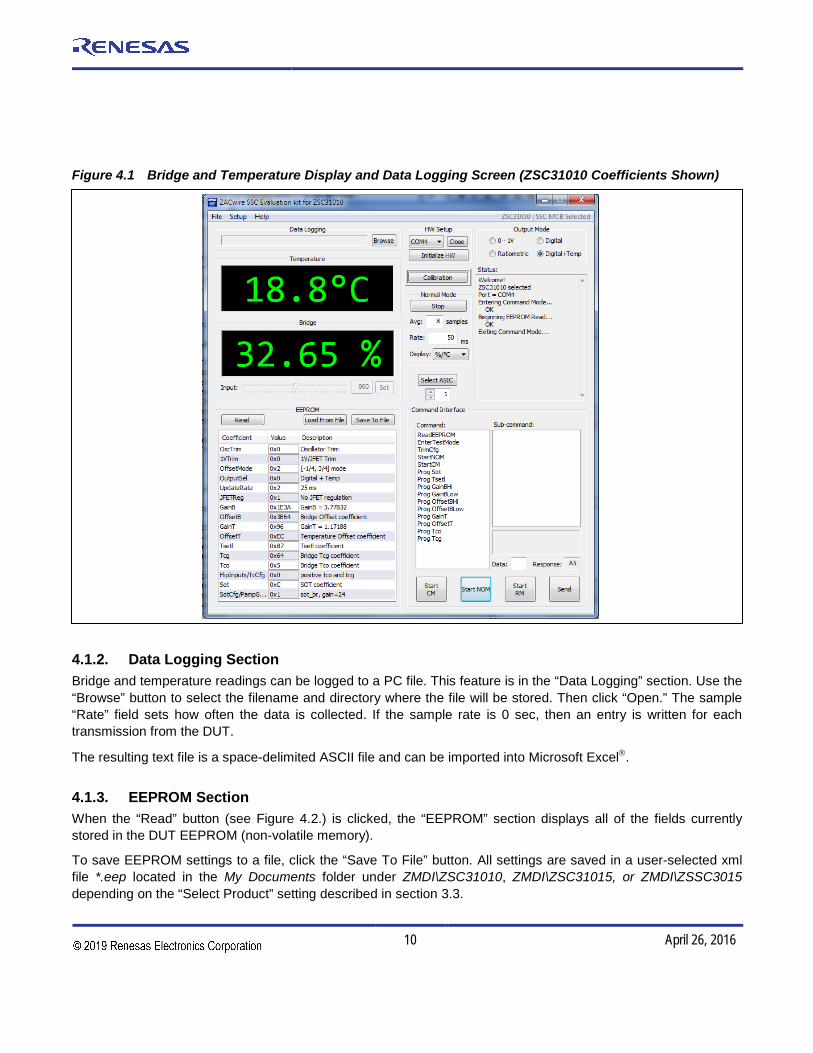
Figure 4.1 Bridge and Temperature Display and Data Logging Screen (ZSC31010 Coefficients Shown)
4.1.2. Data Logging Section Bridge and temperature readings can be logged to a PC file. This feature is in the “Data Logging” section. Use the “Browse” button to select the filename and directory where the file will be stored. Then click “Open.” The sample “Rate” field sets how often the data is collected. If the sample rate is 0 sec, then an entry is written for each transmission from the DUT.
The resulting text file is a space-delimited ASCII file and can be imported into Microsoft Excel.
4.1.3. EEPROM Section When the “Read” button (see Figure 4.2.) is clicked, the “EEPROM” section displays all of the fields currently stored in the DUT EEPROM (non-volatile memory).
To save EEPROM settings to a file, click the “Save To File” button. All settings are saved in a user-selected xml file *.eep located in the My Documents folder under ZMDI\ZSC31010, ZMDI\ZSC31015, or ZMDI\ZSSC3015 depending on the “Select Product” setting described in section 3.3.

ZSC31010 / ZSC31015 / ZSSC3015 ZACwire™ SSC Modular Evaluation Kit Description
© 2016 Integrated Device Technology, Inc. 11 April 26, 2016
To load the default values file ([product name]_default_EEPROM.eep) or previously saved EEPROM settings (user-selected *.eep file), click on the “Load From File” button and browse for the file.
Note: The loaded file will not overwrite the trimming bits (OscTrim and 1VTrim/JFET_Trim for the ZSC31010; IV_Trim/JFET_Trim for the ZSC31015 and ZSSC3015), which are part-specific trimmed in the final test by IDT.
Figure 4.2 EEPROM Section Example (ZSC31010 Coefficients Shown)
4.1.4. Command Interface Section Use the “Command Interface” section to issue commands to the DUT. Descriptions for these commands can be found in the product datasheet. Click “START CM” (Start Command Mode) before sending any commands to the IC. This puts the IC into Command Mode, and the output values in the black display fields do not update. Only the set of commands valid for the selected product (ZSC31010, ZSC31015, or ZSSC3015) is active.
4.1.5. Response Field If the DUT successfully enters Command Mode, it sends an A5H response, which is displayed as A5 in the “Response” field.

ZSC31010 / ZSC31015 / ZSSC3015 ZACwire™ SSC Modular Evaluation Kit Description
© 2016 Integrated Device Technology, Inc. 12 April 26, 2016
4.1.6. Command/Subcommand/Data Fields To send a command to the DUT, click on its text description in the “Command” section. If the command has a sub-command component, then also click the selected sub-command in the “Sub-Command” section. Some commands also require one or more hex digits of data. Enter these in the “Data” field.
4.1.7. Send Button After the desired command and any applicable sub-command are selected and any applicable data has been entered, click “Send.”
4.1.8. Start CM Button To start Command Mode for communication and calibration, click “START CM” (Start Command Mode).
4.1.9. Start NOM Button To exit Command Mode and return the DUT to Normal Operation Mode (reading, conditioning, and transmitting bridge data), click “START NOM” (Start Normal Operation Mode).
4.1.10. Start RM Button When in Raw Mode, the block display fields show the raw values (uncorrected ADC results) for bridge and tem-perature input signals if the bridge gain (Gain_B) is programmed to unity (800H) and the temperature gain (Gain_T) is programmed to unity (80H). The “Start RM” button is provided only as an option for control and analy-sis; it is not typically needed during a standard calibration run.
The Raw Mode can only be entered after entering the Command Mode.
The calibration section of the software will automatically put the DUT in Raw Mode and collect all the raw data needed for a given calibration point.
4.1.11. Normal Mode Section Clicking on the “Collect Data” button collects either raw values or corrected output data depending on the EEPROM settings. If the DUT is programmed in analog output configuration, the software issues a request for analog conversion to the board. This function uses one of the 10-bit (~5mV resolution) ADC channels of the CB. The input to this ADC is connected to the SIGTM pin of the DUT. The result is displayed as a voltage. Note: When entering Normal Mode, data collection is started automatically.
“Avg samples” (Average Samples)
This feature allows averaging the measured values by choosing the number of samples to average before dis-playing the result. Note this is a running average, so increasing the number to average increases the display’s settling time but does not affect the update rate.

ZSC31010 / ZSC31015 / ZSSC3015 ZACwire™ SSC Modular Evaluation Kit Description
© 2016 Integrated Device Technology, Inc. 13 April 26, 2016
“Rate” in ms
This feature allows programming the timing of the data collection, which is especially useful for data logging over a long time. The minimum time is limited by the operating system of the user’s PC and/or the CB functions and is usually 10 to 20 ms.
4.1.12. Output Mode Section In the “Output Mode” section, select the output mode before starting calibration. This selection determines the value range of the output signals as shown in the following table. Additional selections are possible in the “Cali-bration/Set ASIC Configuration” window (click “Calibration” to initialize).
Table 4.1 Output Mode Options
Input Values Chamber Readings
Output Values Depending on Output Selection
Measurement Example (%)
Digital With/Without Temperature
%(Digital)
Ratiometric Analog VDD=5V
(V)
0-1V(V)
10% 10% (204) 0.5 0.1
50% 50%(1024) 2.5 0.5
90% 90%(1834) 4.5 0.9
4.1.13. Adjustment of the Analog Pre-Amp Gain and the Analog ADC Offset Modes The offset parameter is calculated automatically during the calibration procedure, and the result is stored in the EEPROM.
There are 4 programmable offset modes for the ZSC31010/ZSC31015/ZSSC3015:
• [-1/2,1/2]
• [-1/4,3/4]
• [-1/8,7/8]
• [-1/16,15/16]
During the calibration process (“Add New Point”), the software will "acquire" data up to four different times, acquiring data once for each of the 4 different offset modes enabled. The best offset mode to use is calculated automatically by the software, and the result is stored in the EEPROM.
Once the user has a good understanding of the bridge and its performance, the user should choose to disable data acquisition in certain offset modes. This will expedite the calibration process because then data acquisition will not be needed in all 4 modes.

ZSC31010 / ZSC31015 / ZSSC3015 ZACwire™ SSC Modular Evaluation Kit Description
© 2016 Integrated Device Technology, Inc. 14 April 26, 2016
These analog offset modes help compensate for bridges that have a large inherent offset.
The [-1/2, 1/2] mode is best for a balanced bridge [-50mV, 50mV] @ VDD=5V (Pre-Amp=24).
The [-1/16, 15/16] mode is best for positive-skewed bridges [-10mV, 90mV] @VDD=5V (Pre-Amp=24).
The gain term stored in EEPROM used to compensate for span is a digital gain term (a digital number multiplied by the result of the ADC to compensate sensor span). Prior to ADC conversion, however, there is an amplifier (pre-amp). This amplifier amplifies the bridge signal to produce the differential signal converted by the ADC con-version. This amplifier can be programmed to one of four different settings as shown in Table 4.2.
Table 4.2 Programmable Pre-amp Gain Settings
ZSC31010 ZSC31015 ZSSC3015
A=6 A=6 A=6
A=12 A=24(default) A=24(default)
A=24(default) A=48 A=48
A=48 A=96 A=96
Any bridge input signal greater than 40mV/V in differential will saturate the pre-amp if the gain is set to 24 (default). In this case, the pre-amp gain must be set to the next lower value (12 for ZSC31010 or 6 for ZSC31015 and ZSSC3015).
For very small differential input signals, the higher analog gain (48) can improve the output resolution given in the “Analog Inputs versus Output Resolution” section of the datasheet, but the sensor offset must always be considered as well as sensor span. Both the offset and span of the sensor are amplified by the pre-amp. With a high analog gain (48) the total offset plus span cannot exceed 20mV/V differential. Otherwise the input to the ADC will be saturated.
The optimized AFE setting is supported by an Excel™ file [product name]_AFE_Configuration_Selection_revX.X.xls.
4.1.14. Calibration Button To initiate a calibration run, click the “Calibration” button. This results in the calibration screen and dialog box shown in Figure 4.3.

ZSC31010 / ZSC31015 / ZSSC3015 ZACwire™ SSC Modular Evaluation Kit Description
© 2016 Integrated Device Technology, Inc. 15 April 26, 2016
Step 2 – Select calibration method and collect data
Step 3 – Calculate and write coefficients
Step 1 - Initialize
Figure 4.3 Calibration Window Example (ZSC31010 Coefficients Shown)
4.2. Calibration Sequence Although the ZSC31010/ZSC31015/ZSSC3015 can function with many different types of resistive bridges, assume it is connected to a pressure bridge for the following calibration example. In this case, calibration essentially involves collecting raw bridge and temperature data from the IC for different known pressures (and temperatures if desired). This raw data can then be processed by the calibration master (the PC), and the calculated coefficients can then be written to the EEPROM of the IC.
The SSC Evaluation Kit software that IDT provides with the SSC Evaluation Kit is intended for demonstration purposes and calibration of single units. IDT can provide customers with algorithms and assistance in developing their full production calibration software.
ZSC31010 / ZSC31015 / ZSSC3015 ZACwire™ SSC Modular Evaluation Kit Description
© 2016 Integrated Device Technology, Inc. 16 April 26, 2016
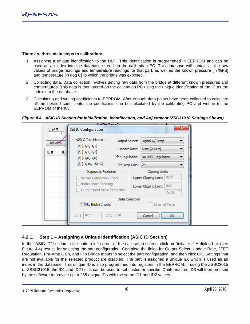
There are three main steps to calibration:
1. Assigning a unique identification to the DUT. This identification is programmed in EEPROM and can beused as an index into the database stored on the calibration PC. This database will contain all the rawvalues of bridge readings and temperature readings for that part, as well as the known pressure [in %FS]and temperature [in deg C] to which the bridge was exposed.
2. Collecting data. Data collection involves getting raw data from the bridge at different known pressures andtemperatures. This data is then stored on the calibration PC using the unique identification of the IC as theindex into the database.
3. Calculating and writing coefficients to EEPROM. After enough data points have been collected to calculateall the desired coefficients, the coefficients can be calculated by the calibrating PC and written to theEEPROM of the IC.
Figure 4.4 ASIC ID Section for Initialization, Identification, and Adjustment (ZSC31010 Settings Shown)
4.2.1. Step 1 – Assigning a Unique Identification (ASIC ID Section) In the “ASIC ID” section in the bottom left corner of the calibration screen, click on “Initialize.” A dialog box (see Figure 4.4) results for selecting the part configuration. Complete the fields for Output Select, Update Rate, JFET Regulation, Pre-Amp Gain, and Flip Bridge Inputs to select the part configuration, and then click OK. Settings that are not available for the selected product are disabled. The part is assigned a unique ID, which is used as an index in the database. This unique ID is also programmed into registers in the EEPROM. If using the ZSSC3015 or ZSSC31015, the ID1 and ID2 fields can be used to set customer specific ID information. ID3 will then be used by the software to provide up to 255 unique IDs with the same ID1 and ID2 values.

ZSC31010 / ZSC31015 / ZSSC3015 ZACwire™ SSC Modular Evaluation Kit Description
© 2016 Integrated Device Technology, Inc. 17 April 26, 2016
Do not disable an ADC offset mode unless the mode will not be needed for the bridge being calibrated. If uncertain, leave all four modes checked. Disabling offset modes only saves time during calibration. For initial evaluations of the ZSC31010/ZSC31015/ZSSC3015, it is best to leave all four modes checked and let the calibration software decide which modes to use (see section 4.1.13).
A Pre-Amp gain of 24 is the default and sufficient for most bridges. Bridges that produce a large signal (>40mV/V differential (max-min)) must use the lower gain setting of 12 for ZSC31010 or 6 for ZSC31015 and ZSSC3015. For bridges that have a small output signal (<2mV/V), using a higher gain setting of 48 will increase output resolution (see section 4.1.13).
4.2.2. Step 2 – Data Collection
Calibration Type Section with the Small Graph
The next step is selecting the type of calibration. The number of unique points (for this example, pressure and temperature points) at which calibration must be performed depends on the user’s requirements. The minimum is a 2-point calibration, and the maximum is a 5-point calibration.
Under “Calibration Type” in the upper left section of the calibration screen (Figure 4.3), there is a smaller graph: X-axis = Temperature, Y-axis = Bridge (pressure for this example). This graph outlines the recommended spreadof points (for this example, pressure and temperature) to be used for calibration.
→ Choose the desired calibration type from the drop-down menu below the smaller graph.
Place the bridge/IC pair to be calibrated in a controlled environment (for this example, pressure/temperature chamber), and stabilize the environment at the first desired calibration point.
Calibration Controls Section
→ Enter the temperature of the chamber (if applicable), as well as the desired read out (in %) of the DUTat this pressure.
→ Click on “Add New Point.” The raw data (pressure and temperature) is obtained from the part, and the pointis displayed on the large graph. It is graphed on the X-axis according to the raw temperature reading from thepart, and on the Y-axis according to the % value entered in the previous step.
→ Change the pressure/temperature of the bridge/IC pair being calibrated and repeat. Take as many morepoints as needed.
Hints:
For better calibration results, choose the temperature and read out (%) values as close as possible to the desired working range.
ZSC31010 / ZSC31015 / ZSSC3015 ZACwire™ SSC Modular Evaluation Kit Description
© 2016 Integrated Device Technology, Inc. 18 April 26, 2016
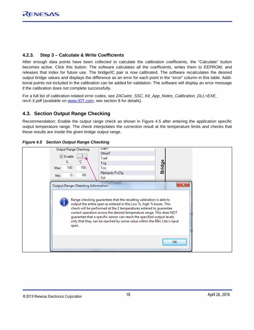
4.2.3. Step 3 – Calculate & Write Coefficients After enough data points have been collected to calculate the calibration coefficients, the “Calculate” button becomes active. Click this button. The software calculates all the coefficients, writes them to EEPROM, and releases that index for future use. The bridge/IC pair is now calibrated. The software recalculates the desired output bridge values and displays the difference as an error for each point in the “error” column in this table. Addi-tional points not included in the calibration can be added for validation. The software will display an error message if the calibration does not complete successfully.
For a full list of calibration-related error codes, see ZACwire_SSC_Kit_App_Notes_Calibration_DLL+EXE_ revX.X.pdf (available on www.IDT.com; see section 8 for details).
4.3. Section Output Range Checking Recommendation: Enable the output range check as shown in Figure 4.5 after entering the application specific output temperature range. The check interpolates the correction result at the temperature limits and checks that these results are inside the given bridge output range.
Figure 4.5 Section Output Range Checking

ZSC31010 / ZSC31015 / ZSSC3015 ZACwire™ SSC Modular Evaluation Kit Description
© 2016 Integrated Device Technology, Inc. 19 April 26, 2016
5 Dry Run Calibration The following directions perform an example of a simple 2-point linear calibration using the SSC Sensor Replace-ment Board (SRB)* and a DMM for measuring the sensor input values between pin 2 (VBP) and pin 4(VPN) of the DUT.
Steps for the Dry Run Calibration 1.) Connect the three boards: the SSC Communication (CB), SSC Evaluation Board, and the SRB. Insert the
ZSC31010/ZSC31015/ZSSC3015 in the SOP-8 socket on the SSC Evaluation Board. The correct orientation for pin 1 is shown in Figure 2.1.
2.) Connect a USB cable from the USB connector on the SSC CB to an available USB port. Verify that the green PWR LED is lit on the SSC CB.
3.) Start the SSC Evaluation Kit software. 4.) Select “SSC Eval Kit’” under “Board Type.” Select the actual product (ZSC31010, ZSC31015, or ZSSC3015)
under “Select Product.” Select the proper COM port. Click on “Initialize Hardware.” 5.) Click on “START CM.” If the setup is correct, A5 is displayed in the “Response” field at the bottom right. 6.) Click on “Calibration.” The calibration window appears (Figure 4.3). 7.) Click on “Initialize” in the ASIC ID section (lower left corner). A dialog box results. Choose “Ratiometric
Analog” as the output selection; “25ms” as the update rate; “No JFET Regulation”; and “normal bridge inputs” (not flipped) and pre-amp gain =24. A unique identifier is assigned to this DUT and is written to its EEPROM. The EEPROM setting will be changed for reading raw values and displayed in the “Coefficient Section.”
8.) In the upper left section of the calibration window, under “Calibration Type,” choose “2-Pt Gain_B & Offset_B” calibration from the drop-down menu. The smaller graph above the drop-down menu indicates the recommended pattern of two bridge readings at the same temperature.
9.) The next step is to start data collection. Normally this would be done with a real bridge attached to the DUT on a remote board in a controlled environment. Instead, this dry run calibration uses the SRB as bridge inputs. a. Turn the red potentiometer on the SRB all the way to the left (about 0 mV).b. Enter 10% in the “Measure %” box in the “Calibration Controls” section.c. Click on “Add New Point.” The software obtains a raw reading from the part and graphs the new data
point.d. Turn the red potentiometer on the SRB all the way to the right (about 110mV).e. Enter 90% in the “Measure %” box.f. Click on “Add New Point” again. The software obtains a new raw reading from the part and graphs the
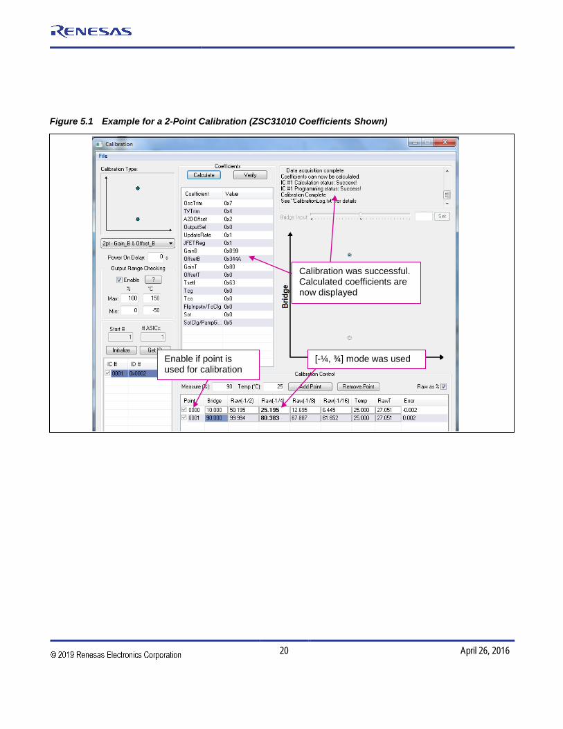
new data point.10.) Because this is a 2-point calibration, the software has all the necessary data for calculating and writing the
coefficients. Click on “Calculate,” which should now be active. 11.) Connect the voltmeter to the analog output. The output voltage will change now from 0.5V to 4.5V with a
clockwise turn of the potentiometer.
* For more information, see ZSC3xxxx_SensorReplacementBoard_DS.pdf.
ZSC31010 / ZSC31015 / ZSSC3015 ZACwire™ SSC Modular Evaluation Kit Description
© 2016 Integrated Device Technology, Inc. 20 April 26, 2016
Enable if point is used for calibration
[-¼, ¾] mode was used
Calibration was successful. Calculated coefficients are now displayed
Figure 5.1 Example for a 2-Point Calibration (ZSC31010 Coefficients Shown)

ZSC31010 / ZSC31015 / ZSSC3015 ZACwire™ SSC Modular Evaluation Kit Description
© 2016 Integrated Device Technology, Inc. 21 April 26, 2016
6 Calculation of Calibration Coefficients Off-line Note This calculation is possible without connecting the kit boards to the PC. Raw and target values can be entered manually or copied using the copy and paste function in Microsoft® Office from an Excel™ table for SSC Evaluation Kit software revisions 2.000 and higher. The values listed in a CalibrationLog_DDMMMYYYY.txt file can also be entered.
Steps for the Off-line Calibration Coefficient Calculation:
(1) Start the SSC Evaluation Kit software and select the product for which the coefficients should be calculated.(2) Click on “Calibrate.” The calibration window appears (see Figure 4.3).(3) Click on “Initialize” in the “Initialization” section (upper left corner). The “Set IC Configuration” window appears
(see Figure 4.4). Click “OK.” The actual setting does not influence the off-line calibration.Note: This is a “blind” initialization, because no part is connected.
(4) Select the desired calibration method. The smaller graph above the pull down menu indicates therecommended pattern of bridge and temperature readings.
(5) Start data collection. Fill in numbers in the “Point” column. The target and raw values can be written/copied inthe related fields. The numbers are [%] for the bridge target and raw readings and [°C] for the temperaturetarget and raw readings.
a. Click on “Add New Point.”b. Enter the first target bridge reading [%] in the “sensor” field and enter the raw value [%] in the “raw”
field. For calibration with temperature compensation, also add the chamber temperature in the “temp”field temperature and raw readings in the “rawT” fields.
c. Repeat a) and b) as needed until all calibration points are entered.
(6) Check the “Valid” check box, and click on the “Calculate” button. The coefficients are stored in theCalibrationLog_DDMMMYYYY.txt file.
(7) Click “View Log” to open this file. For each calibration point, the error for the point is calculated in the samefile.
(8) Additionally, the calibration information can be exported to Microsoft Excel™ or to a Comma Separated Value(CSV) text file. To export the data, go to the File menu and select ‘Export Calibration Data’ and then either‘Export to Microsoft Excel’ or ‘Export to CSV file.’
Note: Instead of entering the raw and target values for the bridge and temperature target and raw values, these values can be transferred from a CalibrationLog_DDMMMYYYY.txt file or from an Excel™ file using the copy/ paste feature. For the example given in Figure 6.1, the Excel™ table should have the number of columns shown in Table 6.1. To copy from or paste to the calibration points table, first click the mouse in the table area, and then type Ctrl+c to copy or Ctrl+v to paste. Important: Copy and paste operations operate on the entire table.

ZSC31010 / ZSC31015 / ZSSC3015 ZACwire™ SSC Modular Evaluation Kit Description
© 2016 Integrated Device Technology, Inc. 22 April 26, 2016
Table 6.1 Example Spreadsheet Data
Point Bridge Raw(-1/2) Raw(-1/4) Raw(-1/8) Raw(-1/16) Temp Raw T
1 10.000 50.208 25.208 12.708 6.451 25.000 26.855 2 50.000 78.553 53.555 41.064 34.821 25.000 26.953 3 90.000 99.994 80.326 67.828 61.594 25.000 26.953
The number of A2D Offset modes selected during initialization determines the number of columns in Table 6.1.
The minimum number of points is determined by the selected calibration method. Additional points can be added. If the points are selected (check box enabled), they will be part of the calibration; otherwise these points will be used for error validation only.
Make sure that the Excel™ table includes only numbers in the correct format (Category: Number). Copying from formula results is not possible.

ZSC31010 / ZSC31015 / ZSSC3015 ZACwire™ SSC Modular Evaluation Kit Description
© 2016 Integrated Device Technology, Inc. 23 April 26, 2016
Validation error in calibration point (recalculation with calibration coefficients)
Target and raw values (e.g., copied from Excel™)
Check box for calibration point selection
Figure 6.1 Fields for Manually Entering Target and Raw Values (ZSC31010 Coefficients Shown)
Note: The temperature output on ZSC31010, ZSC31015 and ZSSC3015 has a resolution of only 8 bits (200ºC/256=0.8 ºC), but the temperature dependency of the bridge input signal is corrected with an internal 12-bit temperature value. The validation error in the calibration points is typically due to rounding errors inherent in fixed-point mathematics (assuming a valid calibration with the minimum number of calibration points).

ZSC31010 / ZSC31015 / ZSSC3015 ZACwire™ SSC Modular Evaluation Kit Description
© 2016 Integrated Device Technology, Inc. 24 April 26, 2016
7 SSC Evaluation Kit Software with the IDT SSC Terminal
7.1. Protocol The microcontroller (type ATmega32) on the SSC Communication Board (CB) enables communication with the SSC Evaluation Board and ZSC31010/ZSC31015/ZSSC3015 using the SSC Evaluation Kit software running on the PC. The serial ZACwireTM protocol is implemented in the microcontroller’s software. The USB_UART IC on the SSC CB transfers the signals from the microcontroller to the USB port of the PC.
For more details see SSC_CommunicationBoard_VX-x_DataSheet_Rev_X_x.pdf.
7.2. IDT SSC Terminal The IDT SSC Terminal is the lowest level of communication for transferring commands from the PC to the microcontroller on the CB. For a full summary and detailed command description of the applicable controller com-mands, see the spreadsheet SSC_CommunicationBoard_CommandSyntax_Rev_X_x.xls, which is included in the software zip file described below.
The SSC Terminal software can be downloaded from the IDT website (http://www.IDT.com).
Navigate to www.IDT.com/SSC-COMM-BD. Click on the link titled “SSC Terminal Program Rev. x” (where x is the current revision) and follow the dialog instructions as needed to download the zip file for the software and then extract the SSC Terminal Vx.exe file. Then double click this file, which will create a ZMDI SSC Terminal icon on the PC desktop. Click on this icon to activate the terminal program.
Table 7.1 SSC Terminal Command Format
Character Order 1 2 3 4,5 6,7,8 <d…d>
ZSC31010/ ZSC31015/ ZSSC3015
R R or W T or _ 00
Comments Read or Write
Trigger Power Cycle or Not
Always 00
Number of Bytes to Read and Write
Blank for Read; Data Bytes to Write
Example R W T 00 002 5000
Hint: If “T” is sent for the 3rd position (instead of “_”), the DUT is powered off and then on. “T” should be used only if power cycling is necessary for operation.

ZSC31010 / ZSC31015 / ZSSC3015 ZACwire™ SSC Modular Evaluation Kit Description
© 2016 Integrated Device Technology, Inc. 25 April 26, 2016
Input Line – Enter command here.
Figure 7.1 below shows a communication example. Write the command in the input line, and press ENTER on the keyboard or click on “Send.” See the current version of the data sheet for the ZSC31010/ZSC31015/ZSSC3015 for more details on commands.
Figure 7.1 SSC Terminal Example
v Readout of SSC CB’s firmware version
t11000 Set trigger timing for 5V, 12V to 0ms Note: The trigger delay must be set!
t_030 Set timing for switching supply off to 30ms off before trigger restarts IC
rrt PowerOn using defined trigger
t00000 Switches off 5V and 12V channels with trigger time preserved
rwt000025090 Start Command Mode with power on using defined delay between power-on and start of communication *
rw_000020000 Read EEPROM *
rw_000023032 Set output mode to ratiometric (See data sheet for command details.)*
rw_000024000 Start Normal Operation Mode
*Note: The Start_CM command example shown in Figure 7.1 (5090HEX) is valid for all products; however, for theZSC31010, the two LSBs of Start_CM command can be any value. The only difference for a ZSC31015 orZSSC3015 communication example is the number of EEPROM bytes returned for an EEPROM read command.ZSC31015 and ZSSC3015 will return 20 bytes, and ZSC31010 will return 14 bytes.
ZSC31010 / ZSC31015 / ZSSC3015 ZACwire™ SSC Modular Evaluation Kit Description
© 2016 Integrated Device Technology, Inc. 26 April 26, 2016
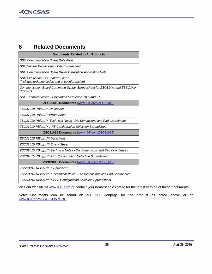
8 Related Documents
Documents Related to All Products
SSC Communication Board Datasheet
SSC Sensor Replacement Board Datasheet
SSC Communication Board Driver Installation Application Note
SSC Evaluation Kits Feature Sheet (includes ordering codes and price information)
Communication Board Command Syntax Spreadsheet for ZSC31xxx and ZSSC3xxx Products
SSC Technical Notes - Calibration Sequence, DLL and EXE
ZSC31010 Documents (www.IDT.com/ZSC31010)
ZSC31010 RBicLite™ Datasheet
ZSC31010 RBicLiteTM Errata Sheet
ZSC31010 RBicLite™ Technical Notes - Die Dimensions and Pad Coordinates
ZSC31010 RBicLite™ AFE Configuration Selection Spreadsheet
ZSC31015 Documents (www.IDT.com/ZSC31015)
ZSC31015 RBicdLite™ Datasheet
ZSC31015 RBicdLite™ Errata Sheet
ZSC31015 RBicdLite™ Technical Notes - Die Dimensions and Pad Coordinates
ZSC31015 RBicdLite™ AFE Configuration Selection Spreadsheet
ZSSC3015 Documents (www.IDT.com/ZSSC3015)
ZSSC3015 RBicdLite™ Datasheet
ZSSC3015 RBicdLite™ Technical Notes - Die Dimensions and Pad Coordinates
ZSSC3015 RBicdLite™ AFE Configuration Selection Spreadsheet
Visit our website at www.IDT.com or contact your nearest sales office for the latest version of these documents.
Note: Documents can be found on our IDT webpage for the product as noted above or on www.IDT.com/SSC-COMM-BD.
ZSC31010 / ZSC31015 / ZSSC3015 ZACwire™ SSC Modular Evaluation Kit Description
© 2016 Integrated Device Technology, Inc. 27 April 26, 2016
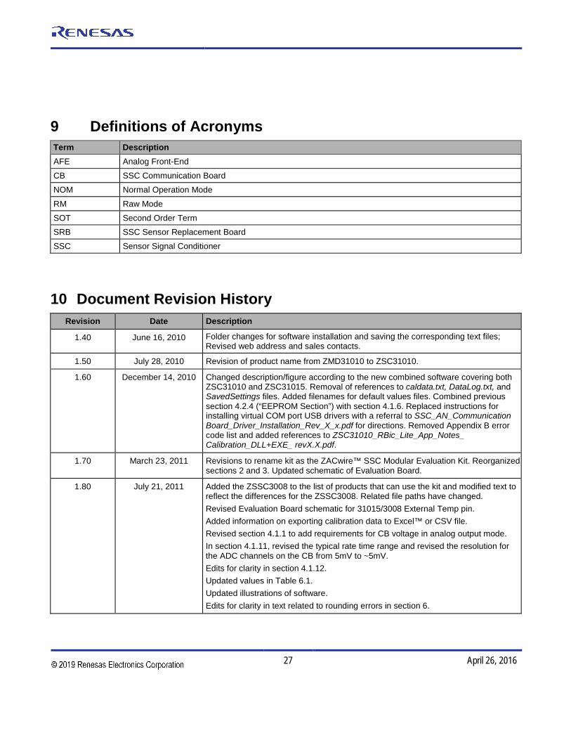
9 Definitions of Acronyms Term Description AFE Analog Front-End
CB SSC Communication Board
NOM Normal Operation Mode
RM Raw Mode
SOT Second Order Term
SRB SSC Sensor Replacement Board
SSC Sensor Signal Conditioner
10 Document Revision History Revision Date Description
1.40 June 16, 2010 Folder changes for software installation and saving the corresponding text files; Revised web address and sales contacts.
1.50 July 28, 2010 Revision of product name from ZMD31010 to ZSC31010.
1.60 December 14, 2010 Changed description/figure according to the new combined software covering both ZSC31010 and ZSC31015. Removal of references to caldata.txt, DataLog.txt, and SavedSettings files. Added filenames for default values files. Combined previous section 4.2.4 (“EEPROM Section”) with section 4.1.6. Replaced instructions for installing virtual COM port USB drivers with a referral to SSC_AN_Communication Board_Driver_Installation_Rev_X_x.pdf for directions. Removed Appendix B error code list and added references to ZSC31010_RBic_Lite_App_Notes_ Calibration_DLL+EXE_ revX.X.pdf.
1.70 March 23, 2011 Revisions to rename kit as the ZACwire™ SSC Modular Evaluation Kit. Reorganized sections 2 and 3. Updated schematic of Evaluation Board.
1.80 July 21, 2011 Added the ZSSC3008 to the list of products that can use the kit and modified text to reflect the differences for the ZSSC3008. Related file paths have changed. Revised Evaluation Board schematic for 31015/3008 External Temp pin. Added information on exporting calibration data to Excel™ or CSV file. Revised section 4.1.1 to add requirements for CB voltage in analog output mode. In section 4.1.11, revised the typical rate time range and revised the resolution for the ADC channels on the CB from 5mV to ~5mV. Edits for clarity in section 4.1.12. Updated values in Table 6.1. Updated illustrations of software. Edits for clarity in text related to rounding errors in section 6.

ZSC31010 / ZSC31015 / ZSSC3015 ZACwire™ SSC Modular Evaluation Kit Description
© 2016 Integrated Device Technology, Inc. 28 April 26, 2016
Revision Date Description
1.81 September 24, 2012 Update for contact information.
2.00 April 18, 2013 Removal of ZSSC3008. Addition of ZSSC3015. Update instructions for software installation. Update for contacts and imagery for cover and headers.
April 26, 2016 Changed to IDT branding.

ZSC31010 / ZSC31015 / ZSSC3015 ZACwire™ SSC Modular Evaluation Kit Description
29 April 26, 2016
Appendix A: Schematic ZSC31010 SSC Evaluation Board†
† Note that the nc pin shown on IC1 is the ExtTemp pin for the ZSC31015 and ZSSC3015.

20
Corporate HeadquartersTOYOSU FORESIA, 3-2-24 Toyosu,Koto-ku, Tokyo 135-0061, Japanwww.renesas.com
Contact InformationFor further information on a product, technology, the most up-to-date version of a document, or your nearest sales office, please visit:www.renesas.com/contact/
TrademarksRenesas and the Renesas logo are trademarks of Renesas Electronics Corporation. All trademarks and registered trademarks are the property of their respective owners.