Zone Terminal User's Manual - Engineered Air LOCKOUT HTG LOCKOUT CHECK FAN CHECK CLG CHECK HTG CHECK...
69
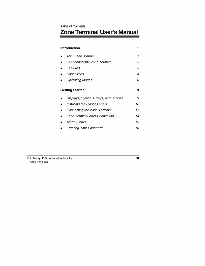
© February, 1994 Johnson Controls, Inc. iii Order No. 633.5 Table of Contents Zone Terminal User’s Manual Introduction 1 ● About This Manual 1 ● Overview of the Zone Terminal 3 ● Features 3 ● Capabilities 4 ● Operating Modes 6 Getting Started 9 ● Displays, Symbols, Keys, and Buttons 9 ● Installing the Plastic Labels 10 ● Connecting the Zone Terminal 11 ● Zone Terminal After Connection 14 ● Alarm Status 15 ● Entering Your Password 16
Transcript of Zone Terminal User's Manual - Engineered Air LOCKOUT HTG LOCKOUT CHECK FAN CHECK CLG CHECK HTG CHECK...
© February, 1994 Johnson Controls, Inc. iiiOrder No. 633.5
Table of Contents
Zone Terminal User’s Manual
Introduction 1
● About This Manual 1
● Overview of the Zone Terminal 3
● Features 3
● Capabilities 4
● Operating Modes 6
Getting Started 9
● Displays, Symbols, Keys, and Buttons 9
● Installing the Plastic Labels 10
● Connecting the Zone Terminal 11
● Zone Terminal After Connection 14
● Alarm Status 15
● Entering Your Password 16

iv Zone Terminal User’s Manual
Making ZT Adjustments 21
● Adjusting Control Settings 21
● Occupied Extend 23
ZT Time Scheduling 25
● Overview 25
● Setting the Current Time 26
● Setting Today’s Date 30
● Planning the Time Schedule 32
● Choosing the Day of the Week 35
● Time Scheduling for Holidays 37
● Temporary Time Scheduling 39
● Setting Begin/End Times 41
Troubleshooting 45
● Internal Diagnostic Errors 49
Appendix A: Time Scheduling Worksheets 51
Appendix B: Glossary 55
Index 63

Controls, Inc. 1
Introduction
The manual contains step-by-step instructions for usingthe Zone Terminal (ZT). It presents information in theorder that you need it.
The manual does not explain how the Zone Terminal isconfigured. For this type of information, see the ZTsection of the HVAC PRO for Windows User’s Manual.
The manual assumes you are familiar with yourbuilding’s general HVAC operation.
Examples
The manual includes examples of the ZT screen that areas realistic as possible, but may not directly apply to yourHVAC system.
About ThisManual
Using the Manual
2 Zone Terminal User’s Manual
Four major sections describe how to use the ZoneTerminal. Appendix A includes Time SchedulingWorksheets, and Appendix B is a glossary of terms.
Introduction and Overview
Explains in general terms the features and operatingmodes of the Zone Terminal.
Getting Started
Includes an explanation of the Keys, Displays, andSymbols on the Zone Terminal. Also includes anexplanation of the Zone Terminal inserts and how toinstall them. In addition, this section instructs the userabout handling Alarm Status, connecting the ZoneTerminal, and entering the Password.
Making ZT Adjustments
Includes specific instructions for making set pointadjustments with the Zone Terminal. Also explains aspecial feature, Occupied Extend.
ZT Time Scheduling
Instructs on how to set the current time and date, andsetting Begin/End times for Occupied, Warmup, andShutdown conditions. Also explains regular day of theweek, holiday, and temporary scheduling.
User’s ManualOrganization

Zone Terminal User’s Manual 3
The Zone Terminal (ZT) is a hand-held or wall-mounteddevice that monitors and adjusts your heating and airconditioning system within a specific building zone. TheZT allows easy access to any zone function available toyour password level.
A telephone-style jack connects the ZT to a JohnsonControls:
● Unitary (UNT) Controller or Variable AirVolume (VAV)Controller through a TE-6100 orTE-64/6500 Series Zone Sensor.
● AHU101 Controller either directly, or through aFunction Module Kit (FMK100) or Relay Kit(RLY100)
The ZT provides:
● portability
● zone system security with three levels of password
● simultaneous monitoring of 3 different settings orvalues plus 18 status points
● easy operation with only seven buttons
● flashing numbers to show which items are ZTadjustable
● flashing symbols to notify you of alarm conditions
Overview of theZone Terminal
Features

4 Zone Terminal User’s Manual
With the ZT, you can:
● quickly identify an alarm and its location
● monitor and adjust up to 18 different settings
● extend a daily time schedule with the OccupiedExtend feature
● add or modify daily, holiday, and temporary timeschedules
To familiarize yourself with the ZT, refer to Figure 1 onthe next page.
Capabilities

Zone Terminal User’s Manual 5
Figure 1: Zone Terminal with Door Open
MONITORADJUSTTIME SCHEDULEPASSWORD
ENTER
FAN STATUSECON ENABLETEMP OCCWARMUP MODECLG LOCKOUTHTG LOCKOUT
A/C LIM OPNCHECK FANCHECK CLGCHECK HTGCHECK ECONDIRTY FILTR
FANCOOL STG #1COOL STG #2HEAT STG #1HEAT STG #2OCCUPIED
ZONE TEMPOUTDOOR TEMP
ZONE HUMIDITYOUTDOOR HUM
TEMP OCC
COOL SET POINTHEAT SET POINT
WARMCOOL ADJACT CLG SPACT HTG SP
DISCH TEMPCLG % ONHTG % ON
ECON % OPENMIN POS % OPN
Building 3Floor 4 AHU12
INSERT 12 ON OFF
ModeSelector Panel
MAP1RT
Door
D isp lay B utton 1
2
3
Display Area 1 1
Display Area 2 1
Display Area 3 1
ALARM

6 Zone Terminal User’s Manual
Four Operating Modes--Monitor, Password, Adjust, andTime Schedule--provide security and allow you tomonitor, adjust, and set time schedules for an individualzone.
As soon as the ZT is connected, it completes a self-check,and then starts up in the Monitor Mode. The MonitorMode allows you to view up to three settings, or sensedvalues, at one time for your HVAC system.
To monitor your system, you must use a clear plasticInsert (a custom-made label) to relate the ZT’s output toyour particular system. (See the Installing the PlasticLabels--Insert section.)
You can simultaneously monitor your HVAC system inthree different ways:
● Monitor up to three different settings or sensedvalues. A maximum of six items are accessible ineach of the three displays.
● Read the symbols to the right of the display numbersto learn the on/off status of various inputs, outputs, ormodes | = On status; ❍ = Off status). This providescontinuous monitoring of 18 different statuses(on/off).
● Monitor alarm status--a flashing red alarm light andany flashing symbol |, ❍, ▲--visually notifies youwhen your HVAC system has an alarm condition.
Operating Modes
Monitor Mode

Zone Terminal User’s Manual 7
The Password Mode allows users with the proper accessrights to adjust system set points and time scheduling.There are three levels of password access:
● Monitor and adjust--password allows user access toadjust only system set points
● Monitor, adjust and time scheduling--passwordallows user access to all ZT features and capabilities,but the system is still password protected
● No password--user is allowed to access all ZTfeatures and capabilities without entering a password
In the Adjust Mode, the ZT displays information in eachof the three numerical displays. Typically, the displaysare set up so that the relationship between the values canbe viewed simultaneously. For example:
Display 1 = Room Temperature
Display 2 = Room Set Point
Display 3 = Output Command
This operating mode allows you to adjust any flashing setpoints that are authorized by your Password. Set pointsadjusted by the ZT remain in effect until you changethem.
Password Mode
Adjust Mode

8 Zone Terminal User’s Manual
In the Time Schedule Mode, you can monitor or adjustthe days and Begin/End times for Occupied, Warmup,and Shutdown conditions. You can also set up holidayand temporary schedules.
Time Schedule Mode is available to those who haveappropriate Password Access.
Time ScheduleMode
Zone Terminal User’s Manual 9
Getting Started
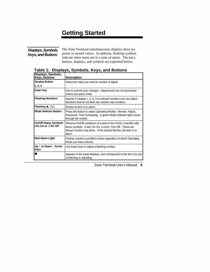
The Zone Terminal simultaneously displays three setpoints or sensed values. In addition, flashing symbolsindicate when items are in a state of alarm. The keys,buttons, displays, and symbols are explained below.
Table 1: Displays, Symbols, Keys, and ButtonsDisplays, Symbols,Keys, Buttons DescriptionDisplay Button
1, 2, 3Select the value you want to monitor or adjust.
Enter Key Use to commit your changes. Adjustments are not processedunless you press Enter.
Flashing Numbers Appear in Display 1, 2, or 3 to indicate numbers you can adjust.Numbers that do not flash are monitor only numbers.
Flashing ▲▲, ❍❍, | Shows an item is in alarm.
Mode Selector Button Press this button to select Operating Modes: Monitor, Adjust,Password, Time Scheduling. A green Mode Indicator light movesthrough the modes.
On/Off Status Symbols| for On or ❍❍ for Off
Observe On/Off conditions of a point in the HVAC controller withthese symbols. A bar | for On, a circle ❍ for Off. These arealways monitor only items. If the symbol flashes, the item is inalarm.
Red Alarm Light Flashes anytime a problem exists regardless of which OperatingMode you have entered.
Up ↑ or Down ↓ ArrowKeys
Use these keys to adjust a flashing number.
●● Appears in the value displays, and corresponds to the item you aremonitoring or adjusting.
Displays, Symbols,Keys, and Buttons

10 Zone Terminal User’s Manual
To use the ZT, you need one of two different types ofplastic labels, which are included with your ZT:
The clear plastic Insert is a custom-made label unique toyour HVAC system. Use this Insert when monitoring oradjusting specific items of your system:
1. With the ZT on a flat surface, press the white tabwith your index finger (Figure 2).
2. Pull the front cover of the ZT away from the backand slide the Insert into position.
3. Press the ZT together and plug in the telephone-stylejack from the controller. With the Insert in place andthe ZT connected, the ● in the top position of eachdisplay lines up with the first word.
INSERT3A
Figure 2: Installing the Insert
Installing thePlastic Labels
Insert

Zone Terminal User’s Manual 11
Use the light gray Time Schedule Overlay whenperforming any function in the Time Schedule Mode.The Overlay, made to cling to the ZT, sticks around theoutside of the display area.
Note: Do not open the ZT case to use the TimeSchedule Overlay.
You can wall-mount the ZT, or use it as a portable toolfor convenient access to any zone functions available toyour password level.
A telephone-style jack connects the ZT to a JohnsonControls Unitary Controller (UNT) or Variable AirVolume (VAV) Controller through a TE-6100 orTE-64/6500 Series Zone Sensor. See Figure 3.
Figure 3: Connect ZT through a TE-6100 orTE-64/6500 Series Zone Sensor
Time ScheduleOverlay
Connecting theZone Terminal
UNT/VAVConnection
SENSORS
Zone Terminal (back)Connected to a TE-6500Series Zone Sensor
Remove cover.
Zone Terminal (back)Connected to a TE-6100Series Zone Sensor

12 Zone Terminal User’s Manual
A telephone-style jack connects the ZT to a JohnsonControls AHU-101 Controller (Figure 4) either directly orthrough a Relay Kit (Figure 5) or a Function Module Kit(Figure 6).
Figure 4: Connecting ZT to AHU-101
AHU ControllerConnection
AHUCTRBD
Open Door
Remove coverConnect ZT here.

Zone Terminal User’s Manual 13
RLYZT
Connect ZT here.
Figure 5: ZT to Relay Kit (AS-RLY-100)
FMKNOTE
Note: Zone Bus wiring must be connected to Relay Kit or Function Module Kit.
Connect ZT here.
Figure 6: ZT to Function Module Kit (AS-FMK-100)

14 Zone Terminal User’s Manual
Figure 7 shows an example of the ZT and its displaysafter connection.
Figure 7: Connected ZT, Insert in Place
Zone TerminalAfter Connection
MONITORADJUSTTIME SCHEDULEPASSWORD
ENTER
FAN STATUSECON ENABLETEMP OCCWARMUP MODECLG LOCKOUTHTG LOCKOUT
A/C LIM OPNCHECK FANCHECK CLGCHECK HTGCHECK ECONDIRTY FILTR
FANCOOL STG #1COOL STG #2HEAT STG #1HEAT STG #2OCCUPIED
OUTDOOR AIRZONE TEMP
STATIC STEPTMIXED AIR LL SP
COOL SET PTHEAT SET PT
WARMCOOL ADJACT CLG SPACT HTG SP
DISCH TEMPCLG % ONHTG % ON
ECON % OPENMIN POS % OPN
ROOFTOP ZTU INSERT 12 ON OFF
Disp lay Button 1
M odeSelector Panel
Mode SelectorBu tton
2
MAP1RT4
Display Ind icator Dot O n/Off Status
3
Operating Mode Indicator
Up/Down Arrow Keys
D oor
D isp lay Item L istW arning Signal
ALARM
NIGHT HTG STPTNIGHT CLG STPT
Display Area 1 1
Display Area 2 1
Display Area 3 1
Alarm Light

Zone Terminal User’s Manual 15
The ZT indicates an alarm as follows (Figure 7):
● The warning signal ▲ flashes to the right of thepoint name if the system operating values are inalarm.
● The On/Off Status bar | or circle ❍ flashes when anOn/Off status is in alarm.
● The red alarm light to the right of the Mode SelectorPanel flashes when any of the above items are inalarm.
Alarms cannot be cleared with the ZT. The problem mustbe corrected by maintenance or repair of the affecteditem.
Alarm Status

16 Zone Terminal User’s Manual
If your system uses the Password feature, you must enterthe Password before you can make changes to the setpoints, or before you gain access to Time Scheduling.
To enter your Password:
1. Open the Mode Selector Panel by pulling the doordown.
2. Press the Mode Selector Button until the green ModeIndicator Light moves next to the word Password .When the Mode Selector Button is in the Passwordposition, a number appears in Display 1. Thisnumber must match the number on the top, center ofyour Insert. If the numbers do not match, the datathat appears in the displays will not match thedescription on the Insert. Replace the incorrectInsert.
Figure 8: Matching the Insert Number
Entering YourPassword
CONFIG1
HOLIDAY NUMBER
ALARM
FAN STATUSECON ENABLETEMP OCCWARMUP MODECLG LOCKOUTHTG LOCKOUT
A/C LIM OPNCHECK FANCHECK CLGCHECK HTGCHECK ECONDIRTY FILTR
FANCOOL STG #1COOL STG #2HEAT STG #1HEAT STG #2OCCUPIED
ZONE TEMPOUTDOOR TEMP
ZONE HUMIDITYOUTDOOR HUM
TEMP OCC
COOL SET PTHEAT SET PT
WARMCOOL ADJACT CLG SPACT HTG SP
DISCH TEMPCLG % ONHTG % ON
ECON % OPENMIN POS % OPN
ROOFTOP ZTU INSERT 12 ON OFF
Number in Display 1 must match typed number on the Insert.
N ote:
DISPLAY AREA 1
INSERT 12
ENT ER
ADJUSTTIME SCHEDULE
ENTE R
PASSWO RD
MONITO R
ENTER
MONITORADJUSTTIME SCHEDULE- PASSWORD-
Zone Terminal User’s Manual 17
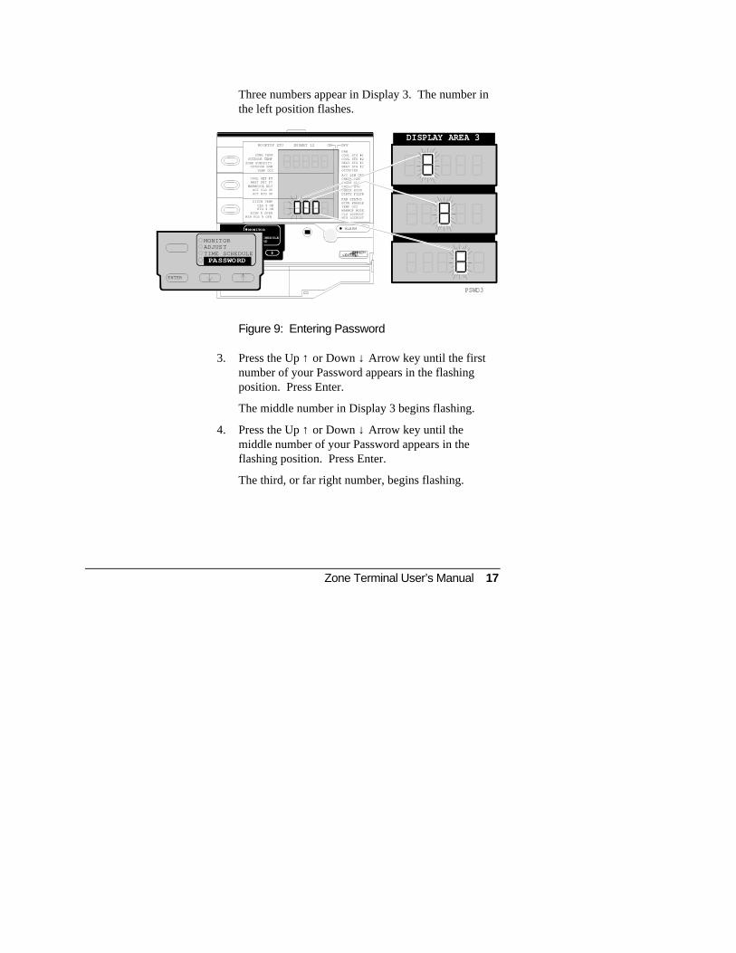
Three numbers appear in Display 3. The number inthe left position flashes.
Figure 9: Entering Password
3. Press the Up ↑ or Down ↓ Arrow key until the firstnumber of your Password appears in the flashingposition. Press Enter.
The middle number in Display 3 begins flashing.
4. Press the Up ↑ or Down ↓ Arrow key until themiddle number of your Password appears in theflashing position. Press Enter.
The third, or far right number, begins flashing.
DISPLAY AREA 3
ALA RM
PSWD3
ADJUSTTIME S CHEDULE
ENTER
PASS WORD
MONITO R
HOLIDAY NUMBER
FAN STATUSECON ENABLETEMP OCCWARMUP MODECLG LOCKOUTHTG LOCKOUT
A/C LIM OPNCHECK FANCHECK CLGCHECK HTGCHECK ECONDIRTY FILTR
FANCOOL STG #1COOL STG #2HEAT STG #1HEAT STG #2OCCUPIED
ZONE TEMPOUTDOOR TEMP
ZONE HUMIDITYOUTDOOR HUM
TEMP OCC
COOL SET PTHEAT SET PT
WARMCOOL ADJACT CLG SPACT HTG SP
DISCH TEMPCLG % ONHTG % ON
ECON % OPENMIN POS % OPN
RO OFTOP ZTU IN SERT 12 ON OFF
ENTER
MONITORADJUSTTIME SCHEDULE- PASSWORD-

18 Zone Terminal User’s Manual
5. Press the Up ↑ or Down ↓ Arrow key until the lastnumber of your Password appears in the flashingposition.
Press Enter.
You must press Enter for each of the three numbersin your Password in order for the ZT to recognize itas a valid Password. If you do not press Enter eachtime, the ZT ignores your Password entry and youcannot gain access to Adjust Mode or TimeScheduling Mode.
After you press Enter for the last number of yourPassword, the green Mode Indicator Light moves next tothe word Adjust in the Mode Selector Panel. If it doesnot go to this position, the Password is incorrect.
You can now begin changing values or set points in theAdjust Mode, or press the Mode Selector Button to movethe green Mode Indicator Light to the Time Scheduleposition. Time Scheduling may require a differentPassword.
Note: The ZT is preset to time out after a1 to 15-minute interval between entries.If you wait too long to enter an adjustment, youmust re-enter your Password. This preventsunauthorized use of the ZT if you forget tocancel your Password.

Zone Terminal User’s Manual 19
After entering the Password, you can easily cancelwithout waiting for the Zone Terminal to time out.
1. Press the Mode Selector Button until the green ModeIndicator Light moves next to the word Password .
2. Press Enter three times. In doing this, you haveentered zeroes as the Password. Access isimmediately canceled because 000 is not a validPassword.
Cancel Password

20 Zone Terminal User’s Manual

Zone Terminal User’s Manual 21
Making ZT Adjustments
This section of the manual is for users who havePassword access to the Adjust Mode.
If you haven’t already entered your Password, you mustdo so. See Entering Your Password.
You can adjust only a flashing number with the ZT. Ifthe number does not flash, that item is a monitor onlyitem.
Adjust Control Settings in Display 1, 2, or 3 as follows:
1. Press the Mode Selector Button until the green ModeIndicator Light moves next to the word Adjust .
2. Press either Display Button 1, 2, or 3 to locateadjustable items, which are indicated by flashingnumbers.
If you continue pressing the display buttons, the dot● in each display changes positions and thecorresponding number appears.
3. Press the Up ↑ or Down ↓ Arrow key until you reachthe number you want to enter. If you hold down theUp ↑ or Down ↓ Arrow keys, you can speed throughthe numbers more quickly. Press Enter.
Adjusting ControlSettings
22 Zone Terminal User’s Manual
After you press Enter, the numbers stop flashing for afew seconds. This pause tells you the ZT hasprocessed your adjustment.
4. Press any of the Display Buttons to make otheradjustments, and repeat Steps 2 and 3.
Notes: Some adjustable set points have high and lowlimits beyond which you cannot adjust them.For example, a heating set point may have anupper limit of 86°F (30°C).
When you make adjustments, they becomepermanent in the ZT. To make a temporarychange, write down the original value beforemaking the change so you can re-enter it later.

Zone Terminal User’s Manual 23
Occupied Extend is a special feature that lets youtemporarily turn the system on for an extended period oftime without going into the Time Schedule Mode.
If your system uses the Occupied Extend feature, you’llfind it listed on the Insert.
No matter what Begin/End time you have scheduled forthe current day, you simply decide how long the systemshould remain on. For example: It is currently 3:30 P.M.and you want the building to stay on until 11 P.M. This isan extension of 7 hours and 30 minutes, which you enteron the ZT.
You can enter any amount of time from 00:00 to 23:59 inOccupied Extend. After the Occupied Extend Scheduleruns, the ZT returns to its regular settings and the erasesthe Occupied Extend Schedule.
To set Occupied Extend:
Remember, if you haven’t already entered your Password,you must do so. Press the Mode Selector Button until thegreen Mode Indicator Light moves next to the wordAdjust .
1. Press the appropriate Display Button until the ● isnext to the words Occupied Extend .
The hours flash.
2. Press the Up ↑ or Down ↓ Arrow key until you reachthe hours you want (0-23). In the above example, wewould choose 7. Press Enter.
The minutes flash.
Occupied Extend

24 Zone Terminal User’s Manual
3. Press the Up ↑ or Down ↓ Arrow key until you reachthe minutes you want (0-59). Based on our example,we would choose 30. Press Enter.
The hours begin flashing again.
These numbers do not pause after you enter them.
You must press Enter after making an adjustment. If youdo not press Enter, the ZT returns the number to itsprevious setting.
Note: The ZT is preset to time out after a certainamount of time passes between entries. If youwait too long to enter an adjustment, you mustre-enter your Password. This preventsunauthorized use of the ZT if you forget tocancel your Password.

Zone Terminal User’s Manual 25
ZT Time Scheduling
This section of the manual is for users who havePassword access to Time Scheduling.
To schedule time, you:
1. Set current time.
2. Set today’s date.
3 Plan the schedule.
4. Choose the day of the week.
5. Set holiday and temporary schedules.
6. Set Begin/End times for Occupied, Warmup, andShutdown.
Overview

26 Zone Terminal User’s Manual
1. Place the plastic Time Schedule Overlay on the ZT.The Overlay clings to the face of the ZT. See Insertin the Installing the Plastic Label section.
2. Enter your Password if you have not already done so.See Entering Your Password.
3. Press the Mode Selector Button until the green ModeIndicator Light moves next to the words TimeSchedule . See Figure 11 showing the TimeSchedule Overlay in place.
Setting theCurrent Time

Zone Terminal User’s Manual 27
The ● in Display 1 is next to the words CurrentTime . The number in the Hours position flashes.
4. If the number in the Hours position is correct, pressEnter.
If the number needs changing, press the Up ↑ orDown ↓ Arrow keys to reach the desired number ofthe current hour (1-23). Press Enter.
The numbers in the Minutes position begin flashing.
Figure 10: Setting the Current Time
CURTMS1
MONITORADJUSTTIME SCHEDULEPASSWORD
ALARM
HOLIDAY DATE
TIME SCHEDULE ON OFF
SATURDAY 7
ENTER
OCCUP CMD
WARMUP CMD
SHUTDOWN CMD
TODAY'S DATEDAY OF WEEK
HOLIDAY NUMBERTE MPOR ARY SCHD
CURRENT TIME
BEGIN WARMUPEND WARMUP
END SHUTDOWN
BEGIN OCCUPIEDEND OCCUPIED
BEGIN SHUTDOWN
Set the hours.
Set the minutes.
Use Up /Dow n Arrow keysto reach desired number. T hen press En te r.
TIME SCHEDULE
CURRENT TIMETODAY'S DATEDAY OF WEEK
HOLIDAY NUMBERTEMPORARY SCHD
Use Up /Dow n Arrow keysto reach desired number. T hen press En te r.
ON OFFTIME SCHEDULE
CURRENT TIMETODAY'S DATEDAY OF WEEK
HOLIDAY NUMBERTEMPORARY SCHD
DISPLAY AREA 1
DISPLAY AREA 1ON OFF
FRIDAY 6
SUNDAY 1MONDAY 2TUESDAY 3WEDNESDAY 4
SATURDAY 7
THURSDAY 5
FRIDAY 6
SUNDAY 1MONDAY 2TUESDAY 3WEDNESDAY 4
SATURDAY 7
THURSDAY 5
THURSDAY 5 FRIDAY 6
SUNDAY 1MONDAY 2TUESDAY 3WEDNESDAY 4

28 Zone Terminal User’s Manual
5. If the number in the Minutes position is correct, pressEnter.
If the Minutes need changing, press the Up ↑ orDown ↓ Arrow keys to reach the desired number (00-59). Press Enter.
The Hours number flashes again. You can reset thecurrent time, or go on to your next adjustment.

Zone Terminal User’s Manual 29
Figure 11: Zone Terminal with Time Scheduling Overlay
MAP2TS
MONITORADJUSTTIME SCHEDULEPASSWORD
ENTER
HOLIDAY DATE
TIME SCHEDULE
SATURDAY
BEGIN OCCUPEND OCCUP
BEGIN WARMUPEND WARMUP
BEGIN SHUTDOWNEND SHUTDOWN
CURRENT TIMETODAY'S DATE
DAY OF WEEKHOLIDAY NUMBERTEMPORARY SCHD
OCCUP CMD
WARMUP CMD
SHUTDOWN CMD
ON OFF
FRIDAY
SUNDAY MONDAY TUESDAY WEDNESDAY THURSDAY
Display Button 1
ModeSelector Panel
Mode SelectorButton
2
Display Indicator Dot On/Off Status
3
Operat ing Mode Indicator
Door
Display Item List Day Numbers
Up/DownArrow K eys
ALARM
Display A rea 1 1
Display A rea 2 1
Display A rea 3 1
123456
7

30 Zone Terminal User’s Manual
Always enter time in 24-hour format. For example:5:00 P.M. is 17:00.
No alarms apply to Time Scheduling. If you see the redalarm light flashing when in the Time Scheduling Mode,an alarm condition exists in the HVAC system. SeeAlarm Status section.
Note: ZT Time Scheduling functions only withcontrollers for which the ZT was configured. Inmost cases, the ZT Time Scheduling isaccessible when it is permanently mounted anddedicated to a specific controller.
Only individuals with Time Scheduling Password Accesscan set Today’s Date. This section of the manual is forusers who have Password access to Time Scheduling.
Remember, the Time Schedule Overlay must be on theface of the ZT. Enter your Password if it is required, andyou haven’t already done so.
1. Press the Mode Selector Button until the green ModeIndicator Light moves next to the words TimeSchedule .
2. Press Display Button 1 until the ● is next to thewords Today’s Date .
The month flashes.
Setting Today’sDate

Zone Terminal User’s Manual 31
Figure 12: Setting Today’s Date
3. If the month is correct, press Enter.
If the month needs changing, press the Up ↑ or Down↓ arrow keys until you reach the correct month (1-12). Press Enter.
The day of the month flashes.
DISPLAY AREA 1
MODA1
MONITO RADJUSTTIME S CHEDULEPASSWO RD
ALARM
HOLIDAY DATE
TIME SCHEDULE ON OFF
SATURDAY 7
ENT ER
THURSDAY 5 FRIDAY 6
OCCUP CMD
WARMUP CMD
SHUTDOWN CMD
TIMETODAY'S DATE
DAY OF WEEKHOLIDAY NUMBER
TEMP SCHEDULE
OCCUP STARTOCCUP STOP
WARMUP STARTWARMUP STOP
SHUTDOWN STARTSHUTDOWN STOP
TIME SCHEDULE
FRIDAY 6
SUNDAY 1MONDAY 2TUESDAY 3WEDNESDAY 4THURSDAY 5
Use U p/Down Arrow keys to reach desired day number.Then press Enter.
Use U p/Down Arrow keys to reach desired mon th number.Then press Enter.
TIME SCHEDULE
FRIDAY 6
SUNDAY 1MONDAY 2TUESDAY 3WEDNESDAY 4THURSDAY 5
TIME SCHEDULE
FRIDAY 6
SUNDAY 1MONDAY 2TUESDAY 3WEDNESDAY 4THURSDAY 5
Use U p/Down Arrow keys to reach desired yea r number.Then press Enter.
DISPLAY AREA 1 ON OFF
ON OFF
ON OFF
DISPLAY AREA 1
CURRENT TIMETODAY'S DATE
DAY OF WEEKHOLIDAY NUMBERTEMPORARY SCHD
CURRENT TIMETODAY'S DATE
DAY OF WEEKHOLIDAY NUMBERTEMPORARY SCHD
CURRENT TIMETODAY'S DATE
DAY OF WEEKHOLIDAY NUMBERTEMPORARY SCHD
SUNDAY 1MONDAY 2TUESDAY 3WEDNESDAY 4

32 Zone Terminal User’s Manual
4. If the day is correct, press Enter.
To change the day, press the Up ↑ or Down ↓ arrowkeys until you reach the correct day of the month (1-31). Press Enter.
After entering the correct month and day, the currentyear setting flashes in Display 1.
5. If the year is correct, press Enter.
To change the year, press the Up ↑ or Down ↓ arrowkeys to set the correct year. Press Enter.
The month and day of the year reappear in Display 1with the month flashing.
You are now ready to plan and enter the Time Schedule.
Note: The ZT changes the necessary date automaticallyfor Leap Year. However, you must manuallyadjust the ZT for Daylight Saving Time changes.
Time Scheduling with the ZT is convenient and easy, butyou’ll want to start with a plan. In Appendix A, you’llfind ZT Scheduling Worksheets to help plan yourOccupied, Warmup, and Shutdown schedules.
Planning theTime Schedule

Zone Terminal User’s Manual 33
The Zone Terminal sets the Time Schedule based on thefollowing order of priority:
1. N2 Bus
2. Occupied Extend
3. Temporary Schedule
4. Holiday Schedule
5. Weekly Schedule
● The Zone Terminal reads and compares only oneBegin and one End time for the current day.
● Once Midnight is reached, the next day’s scheduletakes over.
● You must schedule ONE BEGIN and ONE ENDtime for EACH day. This applies to Occupied,Warmup, and Shutdown.
To avoid an unwanted time scheduling change:
If yourscheduledearlier time isthe...
And you want tothe system tostay
Set
Begin (On) time ON until Midnight End (Off) time at24:00
End (Off) time OFF until Midnight Begin (On) time at24:00
For example:
Begin (On) is setfor 6:00 . . .
You want system onuntil Midnight
Set End (Off) time at24:00
Time SchedulePriority
Rules of TimeScheduling

34 Zone Terminal User’s Manual
Midnight is defined as 00:00. The useful schedulingrange is 00:00 through 23:59. The time setting 24:00flags the ZT to continue a schedule over two or moredays.
Note: In some cases, you may want to cancel ZoneTerminal scheduling commands. You can dothis by scheduling identical Begin/End timeswith the Zone Terminal. See Setting Begin/EndTimes.
To continue with Time Scheduling, read Choosing theDay of the Week. Then refer to Setting Begin/End Times.

Zone Terminal User’s Manual 35
Before entering your Time Schedule, you must firstchoose the day of the week you wish to adjust. A numberfrom 1 through 7 represents each day of the week asshown on the right of the time schedule overlay.
Figure 13: Choosing the Day of the Week
Remember, the Time Schedule Overlay must be on theface of the ZT. Enter your Password if it is required, andyou haven’t already done so.
The far right side of the ZT lists each day of the week.You’ll find a bar | next to the current day of the week.That is, if today is Sunday, the bar | will be next to thenumber 1 (Figure 13).
1. Press the Mode Selector Button if necessary, until thegreen Mode Indicator Light moves next to the wordsTime Schedule .
Choosing the Dayof the Week
DAOFWK
Day of Week
FRIDAY 6
Use Up/Down Arrow keysto reach desired number. Then press Enter.
ON OFFTIME SCHEDULE
CURRENT TIMETODAY'S DATE
DAY OF WEEKHOLIDAY NUMBERTEMPORARY SCHD
SUNDAY 1MONDAY 2TUESDAY 3WEDNESDAY 4THURSDAY 5
MONITORADJUSTTIME SCHEDULE
ACCSEE NUMBER
ALARM
HOLIDAY DATE
TIME SCHEDULE ON OFF
SATURDAY 7
ENTER
OCCUP CMD
WARMUP CMD
SHUTDOWN CMD
TODAY'S DATEDAY OF WEEK
HOLIDAY NUMBERTEMPORARY SCHD
CURRENT TIME
DISPL AY AREA 1
BEGIN WARMUPEND WARMUP
END SHUTDOWN
BEGIN OCCUPIEDEND OCCUPIED
BEGIN SHUTDOWN
THURSDAY 5 FRIDAY 6
SUNDAY 1MONDAY 2TUESDAY 3WEDNESDAY 4

36 Zone Terminal User’s Manual
2. Press Display Button 1 until the ● is next to thewords Day of the Week . The number inDisplay 1 flashes.
3. Press the Up ↑ or Down ↓ arrow keys until you reachthe appropriate number of the day of the week (1-7).After you press the Up ↑ or Down ↓ arrow key,Displays 2 and 3 are blank. Press Enter.
The flashing pauses for a few seconds. This tells youthe ZT recognizes that you have entered a day youwish to adjust or monitor.
4. Press Display Button 3 to enter your planned TimeSchedule. Refer to the Setting the Begin/End Timessection for more information on Time Scheduling.
5. If you wish to set another day, repeat Steps 2 through4.
Note: You must press Enter after each number. If youdo not press Enter, the ZT will return to theprevious setting.
Remember, you have made changes only to the day of theweek you entered in Display 1. Now Refer to the Settingthe Begin/End Times section for more information onTime Scheduling.

Zone Terminal User’s Manual 37
You can schedule up to 10 holidays in advance. Holidaysare numbered from 1-10, and each holiday number can beassigned to a specific date during the year.
The time Schedule Overlay must be on the face of the ZT.Enter your Password if it is required.
1. Press Display Button 1 until the ● is next to thewords Holiday Number . See Figure 14.
Figure 14: Choosing the Holiday
2. To choose a different holiday to monitor or adjust,press the Up ↑ or Down ↓ Arrow key until Display 1shows the holiday you want (1-10). After pressingthe Up ↑ or Down ↓ arrow key, Displays 2 and 3 areblank. Press Enter.
Time Schedulingfor Holidays
Choosing theHoliday
Dis p la y Area 11
HOLIDAY
MONI TORADJU STTIME SCHEDUL EPASS WORD
ALARM
HOLIDAY DATE
TIME SCHEDULE ON OFF
SATURDAY 7
ENT ER
OCCUP CMD
WARMUP CMD
SHUTDOWN CMD
TODAY'S DATEDAY OF WEEK
HOLIDAY NUMBERTEM PORARY SC HD
CURRENT TIME
ON OFFTIME SCHEDULE
CURRENT TIMETODAY'S DATE
DAY OF WEEKHOLIDAY NUMBERTEMPORARY SCHD
FRIDAY 6
SUNDAY 1MONDAY 2TUESDAY 3WEDNESDAY 4THURSDAY 5
SATURDAY 7HOLIDAY DATE
OCCUP CMD
WARMUP CMD
SHUTDOWN CMD
BEGIN OCCUPIEDEND OCCUPIED BEGIN WARMUP
END WARMUPBEGIN SHUTDOWN
END SHUTDOWN
ON OFF
ON OFF
D is p la y Area 21
Dis p la y Area 31
THURSDAY 5 FRIDAY 6
SUNDAY 1MONDAY 2TUESDAY 3WEDNESDAY 4
BEGIN WARMUP
END WARMUP
END SHUTDOWN
BEGIN OCCUPIEDEND OCCUPIED
BEGIN SHUTDOWN

38 Zone Terminal User’s Manual
The flashing holiday number pauses, which indicatesthe ZT recognizes you want to monitor or adjust thatparticular holiday number.
After choosing the Holiday Number in Display 1,you can either set the month and day in Display 2, oradjust the Begin/End times in Display 3.
Some holidays like the Fourth of July and New Year’sDay always have the same date. Others, like Labor Dayor Memorial Day, need to be reassigned to the correctdate each year.
You must adjust each holiday one at a time. After youhave entered your Password, and after you choose thenumber of the Holiday in Display 1:
1. Press Display Button 2. The month flashes.
2. Press the Up ↑ or Down ↓ Arrow key until you reachthe month you wish to enter (1-12). Press Enter.
The day of the month begins flashing.
3. Press the Up ↑ or Down ↓ Arrow key until you reachthe day of the month you wish to enter (1-31). Press Enter.
The month begins flashing again. There is no pauseafter entering these numbers.
4. Press Display Button 3 to enter your planned HolidayTime Schedule.
Changing theHoliday Date
Zone Terminal User’s Manual 39
5. If you wish to set another holiday, repeat Steps 1through 4.
Refer to Setting the Begin/End Times for eachCommand.
Notes: As you adjust the date and the Begin/End times,you are adjusting only the holiday whosenumber appears in Display 1.
The date entered is based on the current year.
You can cancel a holiday schedule by setting theBegin and End Time to 0:00.
You must press Enter each time you enter anumber. If you do not press Enter, the ZT willreturn to its previous setting.
The ZT allows you to set one temporary time schedulethat can be activated for any day of the year. Thisschedule runs only on the date you specify. After theschedule runs, the ZT returns to its regular settings andthe temporary schedule is erased.
1. Press Display Button 1 until the ● appears next to thewords Temporary Schd .
2. Choose the date you want to set by pressing DisplayButton 2. The number in the month position flashes.
3. Press the Up ↑ or Down ↓ Arrow key until you reachthe month you wish to enter (1-12). Press Enter.
The day flashes.
Temporary TimeScheduling

40 Zone Terminal User’s Manual
4. Press the Up ↑ or Down ↓ Arrow key until you reachthe number for the day of the month you wish toenter (1-31). Press Enter.
The month begins flashing. There is no pause afterthese numbers are entered.
5. Press Display Button 3 to enter the times for yourplanned Temporary Schedule.
Refer to the section Setting the Begin/End Times.
Note: You can schedule only one Temporary Schedule.As soon as this Temporary Schedule has run itscourse, the ZT resumes regular scheduling. Youmay, of course, reset the Temporary Schedulefeature over and over again during the year(special holidays, bad weather, shutdowns, etc.)

Zone Terminal User’s Manual 41
You set the Begin/End times for Occupied, Warmup, andShutdown Commands the same way for: Day of theWeek, Holiday, and Temporary Scheduling.
Before you start entering Begin and End Times for TimeScheduling, refer to sections in this manual on:
● Planning the Time Schedule
● Choosing the Day of the Week
● Time Scheduling for Holidays
● Temporary Time Scheduling
● Appendix A: Time Scheduling Worksheets
Remember, the Time Schedule Overlay must be in place,and you must enter your Password if you haven’t alreadydone so.
Schedule only one day at a time. You must set one Beginand one End time for each day. If you are not schedulinga day, enter 00:00 for both the Begin and End Times.
Time is always stated in 24-hour format. For example,5:00 P.M. is stated as 17:00. The useful scheduling rangeis 00:00 through 23:59. Midnight is defined as 00:00.
The time setting of 24:00 flags the ZT to continue aschedule over two days. Refer to the Rules of TimeScheduling section of this document for more informationregarding Time Scheduling rules.
1. Press Display Button 3 and select either Begin or Endfor Occupied, Warmup, or Shutdown.
SettingBegin/End Times

42 Zone Terminal User’s Manual
Figure 15: Occupied, Warmup, and Shutdown Commands--Located inDisplay 3
When you first press Display Button 3,the ● appears next to the words BEGIN OCCUP(or start). The hours in Display 3 flash.
2. If the hour is correct, press Enter.
If the hour needs changing, press the Up ↑ or Down↓ Arrow key until you reach the new hour setting (0to-24). Press Enter.
The minutes now flash.
SSTIME
MONITORADJUSTTIME SCHEDULEPASSWORD
HOLIDAY DATE
TIME SCHEDULE ON OFF
ENTER
CURRENT TIMETODAY'S DATE
DAY OF WEEKHOLIDAY NUMBERTEMPORARY SCHD
BEGIN OCCUPIEDEND OCCUPIEDBEGIN WARMUP
END WARMUPBEGIN SHUTDOWN
END SHUTDOWN
THURSDAY 5 FRIDAY 6
SHUTDOWN CMD
BEGIN SHUTDOWNEND SHUTDOWN
WARMUP CMDBEGIN WARMUPEND WARMUP
OCCUP CMD
D is p lay Area 31
ON OFF
ON OFF
ON OFF D is p lay Area 31
Dis p lay Area 31
BEGIN OCCUPIEDEND OCCUPIED
SUNDAY 1MONDAY 2TUESDAY 3WEDNESDAY 4
SATURDAY 7
ALARM
OCCUP CMD
WARMUP CMD
SHUTDOWN CMD

Zone Terminal User’s Manual 43
3. If the minutes are correct, press Enter.
If the minutes need changing, press the Up ↑ orDown ↓ Arrow key until you reach the new minutesetting (00 to 59). Press Enter.
The hours flash again. No pause occurs afterentering the time.
4. Press Display Button 3 to move to the next Begin orEnd time you want to change.
Repeat Steps 1 through 4 for each day of the week,holiday, or temporary schedule that you want to enter.
Note: You must reset the Time of Day entries forDaylight Saving Time.

44 Zone Terminal User’s Manual

Zone Terminal User’s Manual 45
Troubleshooting
Table 2: TroubleshootingProblem SolutionDisplays remain blankafter ZT is connected
No power is getting to the ZT – check forappropriate connections
Displays show onlydashes- - - - -- - - - -- - - - -
The ZT unit is operational, but notcommunicating with the controller.Check the Zone Bus wire/controller.
Note: The CBLCON switch must be in theNORMAL position.If you do not find wiring errors, downloadthe controller using HVAC PRO,Release 3.0 or later.
Displays show onlydots. . .. . .. . .
The download in the ZT does not matchthe connected controller, or the downloadis invalid. Select the correct download(ZT load file) and re-load the ZT.
Displays show 99999 An entered number is too large to display.
Displays show -9999 An entered number is too small todisplay.
Displays show Err 01 Internal RAM/Processor Error* at powerup.
Displays show Err 02 External RAM Error* at power up.
Displays show Err 03 E2 PROM Error* at power up.
Displays show Err 04 ROM (Code) Error* at power up.
Displays show Err 05 Battery Bad** at power up.
Displays show Err 06 Battery-backed RAM Error* at power up.
Continued on next page . . .

46 Zone Terminal User’s Manual
Problem (Cont.) SolutionRed Alarm lightcontinues to flash.
Fix the HVAC problem causing the alarm.No alarm acknowledge or cancel isavailable.
Numbers in the displaydo not relate to theitems listed on theinsert
The insert is not the correct one for thisZT and controller. Verify the insertnumber by entering Password Mode.
Cannot enter AdjustMode
Have you entered the proper Password?Do you have Password access to thismode?
An otherwiseadjustable analog pointcannot be adjusted
If an N2 Network is present, verify thepoint is overridden. Release the override.If Zone Bus Laptop is connected to thecontroller, verify the point is overridden.Release the override.Verify the display file for thecorresponding configuration in thecontroller, and make the desired pointadjustable.
Binary display pointsare not adjustable
No solution. This is normal operation.
ZT jumps back toMonitor Mode andPassword must be re-entered.
The ZT keyboard has not received akeystroke for a time equal to theKeyboard Idle Time-out as defined in theZT PRO(1 to 15 minutes.) Re-enter yourpassword and continue.Either, increase the Idle Time-out in theZT PRO and re-download.Or, disable the feature in the ZT PRO byentering zero (0) and re-download.
Cannot enter timeScheduling Mode.
Have you entered the proper Password?Do you have Password access to thismode?Is the ZT plugged into the controllerselected for Time Scheduling?
Continued on next page . . .

Zone Terminal User’s Manual 47
Problem (Cont.) SolutionTime and Date cannotbe adjusted and N2 isno longer online.
Wait ten minutes for controller to releasecontrol of the N2 status after the N2 buswas disconnected.If no N2 is connected, or if there is N2 butit has been offline for a least ten minutes,and time and date cannot be adjusted,call the Johnson Controls, Inc. office.
The ZT is not runningthe user's intendedschedule.
Ensure a higher priority schedule is notrunning in place of the desired schedule.Schedule priorities are:• N2 Schedule• Occupied Extend• Temporary Schedule• Holiday schedule• Daily ScheduleVerify the ZT schedules to ensure theyare what you intend. Refer to the TimeScheduling section of this document forinformation on using schedules acrossday boundaries and the use of 24:00 flag.
One minute lapse intime scheduling hasoccurred at Midnight
Enter 24:00 to cross the day boundary.
ZT stays Occupied afterOccupied Extendexpires
Ensure the ZT schedule is as desired. Ifthe schedule for Occupied is disabled(Begin and End times equal) when theOccupied Extend time expires, the ZTreverts to the last schedule. Since theschedule is inactive, Occupied remains inits last state which was ON.
Continued on next page . . .

48 Zone Terminal User’s Manual
Problem (Cont.) SolutionTime Schedule binaries(Occupied, Warm-up,Shutdown) arechanging while theuser edits the ZT TimeSchedule.
You are editing the schedule during theactive day of the week or holiday, and thepresent time is in the window ofadjustment. Make day of week schedulechanges at times other than during thedesired Begin/End times.For holidays, change the date so that it isnot the current date. Edit the schedule,then set the desired date for theschedule.
Alarms show up whenthe system goes intounoccupied mode orshutdown.
Disable alarm reporting by using HVACPRO for the controller configuration or theZT PRO for binary data points (BDs).Use a ZTU100-1.
* For Errors 1, 2, 3, 4, and 6--Repower the device two or threemore times. If the error still exists, disconnect the ZT and rundiagnostics by holding the Display Key 1 and Adjust Down(↓)Key when the phone jack is first plugged in. The word DIAGappears on Display 1 at the start, and all display segments lightup for Pass. When all segments light, push Display Key 1 twotimes, and then follow the prompts.
** For Error 5--This is only a warning indicating the battery-backeddata, specifically Time Scheduling, is lost. If you press Enter,the ZT loads the default time schedule, and you may continue.Replace the battery at your earliest convenience. Use aPanasonic® lithium or Ray-O-Vac®–battery number BR2325.

Zone Terminal User’s Manual 49
To run the ZT's internal diagnostics, hold the Display Key1 and Adjust Down (↓) Key when you plug in the phonejack. The word DIAG appears on Display 1 at the start,and all display segments light up for Pass. When allsegments light, push Display Key 1 two times, and thenfollow the prompts.
Figure 16 illustrates what the ZT is reporting in the eventof an internal diagnostic failure. The digit “1” appears indisplay 2 or 3 to indicate where the error has occurred.
DIAGFAIL
External RAMInternal RAM
E PROMROM Test 2
D is play A rea 11
D isp lay A re a 21
D isp lay A re a 31Battery-BackedRAM Test
Figure 16: Internal Diagnostics
InternalDiagnostic Errors

50 Zone Terminal User’s Manual

Zone Terminal User’s Manual 51
Appendix A:
Time SchedulingWorksheets
To help you plan your time scheduling activities, we’veincluded worksheets on the next two pages. Photocopythe:
● ZT Weekly Time Scheduling Worksheet to plan yourregular daily schedules
● ZT Holiday Time Scheduling Worksheet, whichincludes a space for planning a Temporary Schedule

52 Zone Terminal User’s Manual
ZT WEEKLY TIME SCHEDULING
ZTWEEK
DAY OF
WEEK
1
SUNDAY
2
MONDAY
3
TUESDAY
4
WEDNESDAY
5
THURSDAY
6
FRIDAY
7
SATURDAY
OCCUPIED
BEGIN END
WARMUP
BEGIN END
SHUTDOWN
BEGIN END

Zone Terminal User’s Manual 53
ZT HOLIDAY TIME SCHEDULING
TEMPORARY SCHEDULE
ZTHOL
1
HOLIDAY#
1
2
3
4
5
6
7
8
9
10
OCCUPIED
BEGIN END
WARMUP
BEGIN END
SHUTDOWN
BEGIN END
HOLIDAY
DATE
DATE

54 Zone Terminal User’s Manual

Zone Terminal User’s Manual 55
Appendix B:
Glossary
Air handling control unit into which a Zone Terminal isconnected.
One of four operating modes. Adjust Mode allows you toadjust or change settings in your HVAC system.
A symbol (triangle ▲, bar | , or circle ❍) that flasheswhen a problem exists on a specific monitored orcontrolled item. In addition, a flashing red alarm lightappears to the right of the Mode Selector Panel.
In Time Scheduling, a Begin and End Time must be setfor all three types of system conditions; that is: OccupiedCommand, Warmup Command, and ShutdownCommand. Time is always stated in 24-hour format. Forexample, 5:00 P.M. is stated as 17:00. The usefulscheduling range is 00:00 through 23:59. Midnight isdefined as 00:00. The time setting 24:00 flags the ZT tocontinue a schedule over two days.
(AS-CBLCON-n) A phone cable connector board used tointerface a controller to the ZT.
AHU 100 Controller
Adjust Mode
Alarm Status
Begin/End Times
CBLCON

56 Zone Terminal User’s Manual
Command.
In Time Schedule Mode, refers to the zone conditions of:Occupied (Occup Cmd), Warmup (Warmup Cmd), andShutdown (Shutdown Cmd).
Listed on the Insert--items or points which can bemonitored or adjusted with the ZT. A total of six itemscan be listed in each display.
Numbers that appear in three areas on the face of the ZT,and referred to as Display 1, Display 2, and Display 3.
Buttons located on the left side of the ZT and referred toas Display Button 1, Display Button 2, and DisplayButton 3. Each button corresponds to the displayimmediately to the right of the button. Pressing thebutton allows you to choose another item listed within thesame display.
A button marked Enter located on the front lower left ofthe Mode Selector Panel.
The Zone Terminal connects to a Function Module Kit ifthe Zone Bus wiring is connected between the FMK andits associated controller.
Heating, Ventilating, and Air Conditioning.
CMD
Commands
Control Settings
Display
Display Button
Enter
Function ModuleKit (AS-FMK-100)
HVAC

Zone Terminal User’s Manual 57
An item on Time Scheduling Display 1--used to identifythe holiday.
A clear plastic label custom-made for your HVAC systemand provided with the ZT. Used only in Monitor andAdjust Operating Modes.
A number used to identify the correct Insert. Insert xxrepresents a number specific to your ZT. The number inDisplay 1 (visible only in Password Mode or for the firstfew seconds when the ZT is connected) must match thepre-printed Insert xx number on the top, center of theInsert.
Located in the Mode Selector Panel. A button used tochoose which type of operation you will perform:Monitor, Adjust, Time Schedule, or Password.
Area inside the drop-down door that includes:
● Mode Selector Button with green Mode IndicatorLights
● Enter key
● Up ↑ or Down ↓ Arrow keys
One of four operating modes that allow you to viewsettings or sensed values in the displays without makingadjustments.
Holiday Number
Insert
Insert xx
Mode SelectorButton
Mode SelectorPanel
Monitor Mode

58 Zone Terminal User’s Manual
Normal operating mode for occupant comfort.
A special feature, available in the Adjust Mode, that letsyou turn the system on for an extended period of timewithout going into the Time Scheduling Mode ordisturbing an existing time schedule.
Insert items listed on the right side of Displays 1, 2, or 3indicated with a bar | for On (active) and a circle ❍ forOff (inactive). These On/Off Status items are MonitorOnly items.
Monitor, Adjust, Time Schedule and Password Modeslocated in the Mode Selector Panel.
A 3-digit security number that must be entered into theZT before changes can be made to your HVAC system orto the Time Schedule.
Occupied
Occupied Extend
On/Off Status
Operating Mode
Password

Zone Terminal User’s Manual 59
The Zone Terminal uses three levels of Passwordsecurity.
● Monitor and adjust--password allows user access toadjust only system set points
● Monitor, adjust and time scheduling--passwordallows user access to all ZT features and capabilities,but the system is still password protected
● No password--user is allowed to access all ZTfeatures and capabilities without entering a password
One of four Operating Modes located in the ModeSelector Panel. Password Mode is used to enter Passwordand verify correct Insert number.(See Insert xx.)
The Zone Terminal connects to a Relay Kit if the ZoneBus wiring is connected between the Relay Kit and itsassociated controller.
Values measured by the controller. For example,temperature, humidity, pressure.
Desired point at which the controller is set. For example,a Zone Temperature Set Point could equal 72°F (22°C).
Password Level
Password Mode
Relay Kit(AS-RLY-100)
Sensed Value
Set Point

60 Zone Terminal User’s Manual
All outputs are commanded off or closed. No control ofHVAC equipment occurs.
! WARNING: If Shutdown is used in temperature-extreme environments, thecontroller does not protect for lowtemperature equipment damage.Use other external protectiondevices.
A solid dot ● indicates the item chosen within the threedisplay areas.
A bar | next to the day of the week indicates which day isdisplayed on the ZT.
A solid flashing triangle ▲ indicates the correspondingitem is in alarm.
A bar | for On or a circle ❍ for Off. When flashing,indicates the corresponding On/Off status is in alarm.
The flashing red light in the lower right-hand side of theZT indicates any item above is in alarm.
A green Mode Indicator Light corresponds to theOperating Mode displayed in the Mode Selector Panel.
Shutdown
Symbols

Zone Terminal User’s Manual 61
Time is always stated in 24-hour format. A complete dayis 0:00 to 23:59.
00:00 = Midnight
01:00 = 1:00 A.M.
08:00 = 8:00 A.M.
12:00 = Noon
18:00 = 6:00 P.M.
22:00 = 10:00 P.M.
24:00 = Flag for the ZT to continue a scheduleover two days
A one-time temporary time schedule that operates insteadof the weekly schedule for that day.
A preprinted plastic label provided with the ZT andplaced on the front of the ZT and used for TimeScheduling.
One of four Operating Modes located in the ModeSelector Panel. System Begin/End Times for normalworking days, holidays, and temporary schedules are setin the Time Schedule Mode.
Unitary Controller into which a ZT can be connectedthrough a TE-6100 or TE-64/6500 Series Zone Sensor, orAS-CBLCON-0.
24-Hour Format
TemporarySchedule
Time ScheduleOverlay
Time ScheduleMode
UNT

62 Zone Terminal User’s Manual
Located in the Mode Selector Panel--The Up ↑ or Down↓ Arrow keys are used to reach a desired number in anyof the displays.
Variable Air Volume Controller into which a ZT can beconnected through a TE-6100 or TE-64/6500 Series ZoneSensor, or AS-CBLCON-0.
An operating mode used to bring the building up to anoccupant comfort level.
A sensor into which the ZT is connected.
A hand-held or wall-mounted device that is used tomonitor, adjust, and time schedule your HVAC systemwithin a specific building zone.
Up ↑ or Down ↓Arrow Keys
VAV
Warmup
TE-6100 orTE-64/6500 SeriesZone Sensor
Zone Terminal (ZT)

Zone Terminal User’s Manual 63
Zone Terminal User’s Manual
Index
A
Adjusting Control Settings, 21
Alarm Status, 15
On/Off Status bar | or circle ❍, 15
red alarm light, 15
warning signal ▲, 15
B
Begin/End Times, 41
C
Capabilities, 4
Connecting a Zone Sensor, 11
Connecting ZT, 11
illustration, 14
to a Function Module Kit, 12
to a Function Module Kit, illustration, 13
to a Relay Kit, 12
to a Relay Kit, illustration, 13
to an AHU Controller, 12
to UNT/VAV, 11

64 Zone Terminal User’s Manual
D
Displays, Symbols, Keys, and Buttons
Table, 9
F
Features, 3
G
Glossary, 55
H
Holiday Time Scheduling, 37
Changing the Holiday Date, 38
Choosing the Holiday, 37
Choosing the Holiday, illustration, 37
Holiday Time Scheduling Worksheet, 51
L
Labels, 10
Insert
Matching the Insert Number, 16
Installing
Insert, 10
Time Schedule Overlay, 11
Installing the Insert, illustration, 10

Zone Terminal User’s Manual 65
M
Manual Organization, 2
Getting Started, 2
Introduction and Overview, 2
Making ZT Adjustments, 2
ZT Time Scheduling, 2
O
Occupied Extend, 23
Operating Modes Summaries, 6
Adjust Mode, 7
Monitor Mode, 6
Password Mode, 7
Time Schedule Mode, 8
P
Password, 16
Cancel Password, 19
enter, 16
Entering Password, illustration, 17
Matching Insert Number, 16
Matching the Insert Number, illustration, 16

66 Zone Terminal User’s Manual
T
Temporary Schedule Worksheet, 51
Temporary Time Scheduling, 39
Time Scheduling, 25
Overview, 25
Planning, 32
Priority, 33
Rules, 33
Setting Current Time, illustration, 27
Setting the Current Time, 26
Setting Today’s Date, 30
Setting Today’s Date, illustration, 31
ZT with Overlay, illustration, 29
Troubleshooting, 45
W
Weekly Time Scheduling
Choosing Day of Week, 35
Choosing the Day of the Week, illustration, 35
Weekly Time Scheduling Worksheet, 51
Worksheets, 51
Z
Zone Terminal with Door Open, illustration, 5

Zone Terminal User’s Manual 67