ZJ Lube&Maintenance
24
LUBRICATION AND MAINTENANCE CONTENTS page page CHASSIS AND BODY . . . . . . . . . . . . . . . . . . . . 21 DRIVE TRA IN . . . . . . . . . . . . . . . . . . . . . . . . . . . 17 ENGINE MAINTE NANCE . . . . . . . . . . . . . . . . . . 11 GE NERAL INFORMA TION . . . . . . . . . . . . . . . . . . 1 GENERAL INFORMATION INDEX page page Cla ssification of Lubricants . . . . . . . . . . . . . . . . . . . 2 Component s Requir ing No L ubrication . . . . . . . . . . 3 Fuel Requir ements . . . . . . . . . . . . . . . . . . . . . . . . . 2 Intr oduc ti on . . . . . . . . . . . . . . . . . . . . . . . . . . . . . . 1 Lubrication and Replacement Parts Recommendati on . . . . . . . . . . . . . . . . . . . . . . . . 3 Routine Maint enance . . . . . . . . . . . . . . . . . . . . . . . 2 Sta rti ng Assistanc e (Ju mp St art ing) . . . . . . . . . . . . 7 Vehi cle Li fti ng Rec ommendati ons . . . . . . . . . . . . . . 8 Vehi cle T owi ng Recommendations . . . . . . . . . . . . . 9 INTRODUCTION Lubrication and maintenance is divided into re- quired and recommended service tasks. The required service tasks must be completed to verify emis s i on controls function correctly. The recommended service tasks should be completed to maintain safety and durability. This informat ion will assist service personnel in providing m aximum protection for each owner’s ve- hicle. Conditions can vary with individual driving ha bits. It is necessary to schedule maintenance as a time interval a s well as a distance interval. It is the owner’s responsibility to determine appli- cable dr iving condition. Also t o h ave vehicle servic ed according to t he ma intenance schedule, a nd t o pay for necessary parts and labor. Vehi cles with a Gross V ehicle Weight Rating (GVWR) of 3 855 kg (8,500 lbs.) or less must conform to light duty emission standards. Vehicles with a Gross Vehicle Weight Rating (GVWR) of 3 856 kg (8,501 lbs.) or more must conform to heavy duty emis- sion standards. The GVWR for each vehicle is listed on the Safety Certification Label. This la bel is a ffixed to driver side door pillar (Fig. 1). Additio nal maintenance a nd lubrication informa- tion is listed in the Owner’s Manual. SEVERE DRIVING CONDITIONS Ve h icles subj ected to severe driving conditions should decrease the interval between component maintenance. Severe driving conditio ns are defined a s: • Frequent short trip driving less than 24 km (15 miles) • Frequent driving in dusty conditions • T ra iler towing • Extensive engine idling • S usta ined high speed operation • Desert operation • Frequent start ing and s t o pp ing • Cold climate operation Fig. 1 Vehicle Safety Certification Label Z LUB RICA TION AND MAINTE NANCE 0 - 1
-
Upload
oguzhan-tekce -
Category
Documents
-
view
36 -
download
1
Transcript of ZJ Lube&Maintenance

7/16/2019 ZJ Lube&Maintenance
http://slidepdf.com/reader/full/zj-lubemaintenance 1/24
LUBRICATION AND MAINTENANCE
CONTENTS
page page
CHASSIS AND BODY . . . . . . . . . . . . . . . . . . . . 21DRIVETRAIN . . . . . . . . . . . . . . . . . . . . . . . . . . . 17
ENGINE MAINTENANCE . . . . . . . . . . . . . . . . . . 11GENERAL INFORMATION . . . . . . . . . . . . . . . . . . 1
GENERAL INFORMATION
INDEX
page page
Classification of Lubricants . . . . . . . . . . . . . . . . . . . 2Components Requiring No Lubrication . . . . . . . . . . 3Fuel Requirements . . . . . . . . . . . . . . . . . . . . . . . . . 2Introduction . . . . . . . . . . . . . . . . . . . . . . . . . . . . . . 1Lubrication and Replacement Parts
Recommendation . . . . . . . . . . . . . . . . . . . . . . . . 3
Routine Maintenance . . . . . . . . . . . . . . . . . . . . . . . 2Starting Assistance (Jump Starting) . . . . . . . . . . . . 7Vehicle Lifting Recommendations . . . . . . . . . . . . . . 8Vehicle Towing Recommendations . . . . . . . . . . . . . 9
INTRODUCTIONL u br i ca t i on a n d m a i n t en a n ce i s d iv id ed i n t o r e -
quired and recommended service tasks. The required
se r vice t a sk s m u st be com p le t ed t o ver i f y e m ission
controls function correctly. The recommended service
t a s k s s h ou ld b e c om p le t ed t o m a i n t a i n s a f et y a n d
durability.Th is in for m a t ion w il l a ssist se r vice p er son n e l in
providing m aximum protection for each owner’s ve-
hicle.
C o n dit ion s ca n va r y w it h in d ivid ua l d r ivin g h a bit s .
I t i s n e ce ss a r y t o s c he du l e m a i n t en a n ce a s a t i m e
in t e rva l a s w e ll a s a d ist a n ce in t e r va l .
It is the owner’s responsibility to determine appli-
cable dr iving condition. Also t o h ave vehicle serviced
according to t he ma intenan ce schedule, a nd t o pay for
necessary parts and labor.
Veh icl es w i t h a G r os s Veh icl e Wei gh t R a t i ng
(G VWR) of 3 855 kg (8,500 lbs.) or less must conformt o l ig h t d u t y em i ss ion s t a n d a r d s . Veh i cl es w i t h a
G r o ss Ve h icle We ig h t Ra t in g (G V WR) of 3 856 k g
(8,501 lbs.) or more must conform to heavy duty emis-
sion st a n d a r d s.
The GVWR for each vehicle is listed on the Safety
Certificat ion La bel. This la bel is a ffixed to driver side
door pillar (Fig. 1).
Ad d it ion a l m a in t e n a n ce a n d lu br ica t ion in for m a -
tion is listed in the Owner’s Manual.
SEVERE DRIVING CONDITIONS
Ve h icle s su bje ct e d t o se ve r e d r ivin g con d it ion s
s h ou ld d ecr ea s e t h e i n t er v a l b et w e en com p on en tm a in t e n a n ce. S e ver e d r ivin g con d it ion s a r e d e fin ed
a s:
• F r eq u en t s h or t t r i p d r i vi n g l e ss t h a n 24 k m (15
miles)
• Frequent dr iving in dusty conditions
• Tra iler t owing
• Extensive engine idling
• Sust ained h igh speed opera tion
• Desert operation
• F r e q u en t st a r t in g a n d st op pin g
• Cold climate operation
Fig. 1 Vehicle Safety Certification Label
Z LUBRICATION AND MAINTENANCE 0 - 1

7/16/2019 ZJ Lube&Maintenance
http://slidepdf.com/reader/full/zj-lubemaintenance 2/24
• Commercial service
When a vehicle is continuously subjected to severe
driving conditions, lubricate:
• Body components
• All driveline coupling joints
• Steering linkage
More often t ha n n ormal driving conditions
DUSTY AREAS
With this type of severe driving condition, special
care should be given t o:
• Engine a ir clean er filter
• PCV filter
• Crankcase ventilat ion system
• B rake booster control va lve air f ilter.
OFF-ROAD (4WD) OPERATION
After off-road (4WD) operat ion, ins pect underside of
vehicle. I nspect:
• Tires
• Body structure
• Steering components
• Sus pension components
• Ex h a u st sy st e m
• Threaded fasteners
HARSH SURFACE ENVIRONMENTS
After long operation in harsh environments, brake
drums, brake linings, and rear wheel bearings should
be inspected a nd cleaned.
ROUTINE MAINTENANCE
The following routine maintenance is recommendedon a monthly basis:
TIRE S—Inspect tires for unusua l wear /da ma ge.
BATTERY—Inspect and clean terminals. Determine
acid level a nd a dd dist illed wa ter, if necessar y.
F L U I D S — D e t er m in e i f com p on e n t f luid leve ls a r e
acceptable. Add fluid, if necessary.
LIG HTS/EL EC TRIC AL—Test a ll electrical syst ems
in vehicle for proper operat ion.
I t is a lso r e co m m e n d e d t h a t e n g in e o i l a n d w a sh e r
fluid level be determined at each fuel fill-up.
FUEL REQUIREM ENTSGASOLINE ENGINES
All engines require use of unleaded gasoline to re-
duce harmful effects of lead to the environment. Also
u n le a d e d f u e l is n e ce ssa r y t o p r e ve n t d a m a g e t o t h e
cat a lytic converter/O2
sensor. Fuel must have a mini-
mum octane rat ing of 87.
CAUTION: UNLEADED FUEL ONLY must be used in
vehicles equipped with a catalyst emission controlsystem. All vehicles have reminders printed on theinstrument panel below fuel gauge and on fuel filler
door. Vehicles also have fuel filler tubes that are
specially designed to accept only small-diameter
nozzles.
CLASSIFICATION OF LUBRICANTSLubricating fluids and chassis lubricants are classi-
fied a ccording t o sta nda rds r ecommended by:
• Society of Automotive Engineers (SAE)
• American P etroleum Inst itute (AP I)
• N a t io n a l L u br ica t in g G r e a se I n st i t u t e (N L G I )
ENGINE OIL (FIG. 2)
SAE VISCOSITY GRADE
An SAE viscosity grade is used to specify viscosity
of engine oil. S AE 30 specifies a single viscosity en-
gine oil.
Engine oils a lso ha ve multiple viscosit ies. These a re
specified with a dual SAE viscosity grade which indi-
cates cold-to-hot temperature viscosity range.
API SERVICE GRADE
The API Service Grade specifies the type of perfor-
mance engine oil is intended to provide. API Service
Grade specifications also apply to energy conserving
engine oils.
Conformance to API Service Grade specifications is
d e t e r m in e d by t e st s t h a t m e a su r e a bil i t y o f a n o i l t o
control:
• En g in e w e a r
• Bearing corrosion
•
Sludge• Varnish
• Oil thickening
• Rust
• P iston deposits
For maximum gasoline engine protection, use API
Service G ra de SG , S G /CD or SG /CE engine oil.
Fig. 2 SAE Oil Viscosity Grade & API Service Grade
0 - 2 LUBRICATION AND M AINTENANCE Z
7/16/2019 ZJ Lube&Maintenance
http://slidepdf.com/reader/full/zj-lubemaintenance 3/24
GEAR LUBRICANTS
A d u a l g r a d e i s a l s o u s ed t o s peci fy v is cos it y of
multi-purpose gear lubricants.
AP I g r a d e d e sig n a t ion id en t i f ie s g e a r lu br ica n t s in
terms of recommended usa ge.
MoparS y n t h e t i c G e a r l u b e i s r e q u i r e d f o r u s e i n
vehicles with a trailer towing package.
CHASSIS COMPONENT AND WHEEL BEARING
LUBRICANTS
C h a ssis a n d w h e e l be a r in g lu br ica n t s t h a t a r e r e c-
om m e n d ed a r e id en t i f ie d by t h e N L G I C e r t i fica t ion
S y m bol. Th e sy m bol con t a in s a cod e d d e sig n a t ion .
This identifies usage and quality of the lubricant .
Th e le t t e r G w it h in t h e sy m bol d e sig n a t e s w h e el
b ea r i n g l ub r ica n t . Th e l et t e r L d es ig n a t e s ch a s s is
lu br ica n t . Wh e n t h e let t e r s a r e com bin ed , t h e lu br i-
cant can be used for dual applications.
LUBRICATION AND REPLACEMENT PARTS REC-
OMMENDATIONJ eepvehicles ar e engineered t o provide ma ny years
of dependable operation. However, lubrication service
an d m aint enance ar e required for each vehicle. When
necessary, MOPARbr a n d lu br ica n t s a n d g e n u in e r e -
pl a cem en t pa r t s a r e h ig hl y r ecom m en d ed . E a c h
MOPARbr a n d lu br ica n t a n d r e pla cem e n t p a r t is d e -
signed and to provide dependability and long service
life.
COMPONENTS REQUIRING NO LUBRICATIONTh er e a r e m a n y com pon en t s t h a t s h ou ld n ot b e
lubricated. The components that should not be lubri-
ca t e d a r e :
• Generator bearings
• B ra ke booster cylinder
• Distributors
• Drive belts• Drive belt idler pulleys
• I d ler a r m s
• Rubber bushings
• Starter motor bearings
• Suspension strut bearings
• Rear wheel bearings
• Thrott le control cables
• Throttle linkage ball joints
• Wa ter pump bear ings
Fig. 3 NLGI Lubricant Container Certification/Identification Symbol
Z LUBRICATION AND MAINTENANCE 0 - 3

7/16/2019 ZJ Lube&Maintenance
http://slidepdf.com/reader/full/zj-lubemaintenance 4/24
SCHEDULED MAINTENANCE —ZJ VEHICLES (EXCEPT CALIFORNIA)
SCHEDULED MAINTENANCE —ZJ VEHICLES (EXCEPT CALIFORNIA)
0 - 4 LUBRICATION AND MAINTENANCE Z

7/16/2019 ZJ Lube&Maintenance
http://slidepdf.com/reader/full/zj-lubemaintenance 5/24
SCHEDULED MAINTENANCE —ZJ VEHICLES (CALIFORNIA)
SCHEDULED MAINTENANCE —ZJ VEHICLES (CALIFORNIA)
Z LUBRICATION AND MAINTENANCE 0 - 5

7/16/2019 ZJ Lube&Maintenance
http://slidepdf.com/reader/full/zj-lubemaintenance 6/24
GENERAL MAINTENANCE SERVICES FOR PROPER VEHICLE PERFORMANCE
GENERAL MAINTENANCE 4.0L ENGINES GENERAL MAINTENANCE 5.2L ENGINES
0 - 6 LUBRICATION AND MAINTENANCE Z

7/16/2019 ZJ Lube&Maintenance
http://slidepdf.com/reader/full/zj-lubemaintenance 7/24
STARTING ASSISTANCE ( JUMP STARTING)
WARNING: DO NOT ATTEMPT TO PUSH OR TOW AVEHICLE TO START THE ENGINE. UNBURNED FUEL
COULD ENTER THE EXHAUST CATALYTIC CON-VERTER AND IGNITE AFTER THE ENGINE ISSTARTED. THIS COULD CAUSE THE CONVERTERTO OVERHEAT AND RUPTURE.
BOOSTER BATTERY
WARNING: TO PREVENT PERSONAL INJURY, DO
NOT ALLOW BATTERY ACID TO CONTACT EYES,SKIN OR CLOTHING. DO NOT LEAN OVER A BAT-TERY WHEN CONNECTING JUMPER CABLES. DONOT ALLOW THE POSITIVE AND NEGATIVE CABLE
CLAMPS TO CONTACT EACH OTHER. KEEP OPENFLAMES AND SPARKS AWAY FROM THE BATTERYACID VENT HOLES. ALWAYS WEAR EYE PROTEC-TION WHEN INVOLVED WITH VEHICLE BATTERIES.
If it becomes necessary to use a booster battery and
ju m p er ca ble s t o st a r t a n e n gin e, u se t h e f ol low in g
procedure.
(1) E n g a g e p a r ki n g b r a k e. S h i ft a u t om a t i c t r a n s -
m issio n t o PARK (i f a m a n u a l t r a n sm issio n , sh if t t o
NEUTRAL).
(2) Turn off a ll lights, a nd all other electrical loads.
WARNING: ACID IN A DISCHARGED BATTERY CAN
FREEZE. DO NOT ATTEMPT TO JUMP START AN
ENGINE BEFORE CHECKING CONDITION OF BAT-
TERY ACID. BATTERY COULD EXPLODE AND
CAUSE SEVERE PERSONAL INJURY.
CAUTION: Do not permit metal surfaces on vehicles
to contact. This could establish ground (negative)
continuity between vehicle bodies. This could cause
on-board computers to be damaged.
(3) At t a ch a r e d ju m p er ca ble con n e ct o r cla m p t o
posit ive (+ ) termina l on booster bat tery. Atta ch other
red cable connector clam p to posit ive (+ ) termina l on
dischar ged ba ttery (Fig. 4).
CAUTION: Do not allow positive (+) and negative (-)
cable clamps to contact each other.
WARNING: DO NOT CONNECT A JUMPER CABLE
CONNECTOR CLAMP TO NEGATIVE POST OF DIS-
CHARGED BATTERY.
(4) Connect a black jumper cable connector clam p
to n egative (-) termina l on booster bat tery. Connect
FLUID CAPACITIES
Z LUBRICATION AND MAINTENANCE 0 - 7

7/16/2019 ZJ Lube&Maintenance
http://slidepdf.com/reader/full/zj-lubemaintenance 8/24
other black jumper cable connector clam p t o a good
ground source on engine tha t is to be st ar ted (Fig. 5).
Verify engine ground (negative) contact sur-
face area is free of grease. Make sure there is a
good connection to bare metal. The engine
ground (negative) connection must provide
good electrical continuity.
(5) Start engine.
WARNING: THE USE OF ANY JUMPER CABLE DIS-
CONNECTION PROCEDURE OTHER THAN THAT DE-
SCRIBED BELOW COULD RESULT IN:
• P E R S O N AL I N J U R Y C AU S E D B Y B ATTE R Y
ACID SQUIRTING FROM BATTERY VENTS
• P ERS ONAL INJ URY AND/OR P ROP ERTY DAM-
AGE CAUSED BY BATTERY EXPLOSION
• D AMAG E TO TH E B O O S TER VEH I C L E O R D I S -
AB L ED V EH I C L E C H ARG I N G S YS T EM.
(7) After engine is started, jumper cables must be
disconnected in following order:
• Black (negative) cable connector clamp from engine
ground contact
• Black (negative) cable connector clamp from nega-
tive terminal (-) on booster battery
• Red (positive) cable connector clamps from positive
(+ ) terminals on both bat teries
PORTABLE STARTING UNIT Th er e a r e m a n y t y pe s of p or t a b l e s t a r t i n g u n it s
available for start ing engines. Follow manufacturer’s
instructions.
VEHICLE LIFTING RECOMMENDATIONSRefer to Ow ner’s Manua l for emergency vehicle lift-
ing procedures.
FLOOR JACK
When properly positioned, a floor jack can be usedt o l if t a veh icle (F ig . 6). S u p por t veh icle in r a ise d
p o s i t i o n w i t h j a c k s t a n d s a t f r o n t a n d r e a r e n d s o f
f r a m e r a i ls .
CAUTION: Do not attempt to lift a vehicle with a
floor jack positioned under:
• An axle tube
Fig. 4 Positive Jumper Cable Connection
Fig. 5 Both Jumper Cables Connected On Disabled Vehicle
Fig. 6 Correct Vehicle Lifting Locations—Typical
0 - 8 LUBRICATION AND M AINTENANCE Z

7/16/2019 ZJ Lube&Maintenance
http://slidepdf.com/reader/full/zj-lubemaintenance 9/24
• A body side sill
• A steering linkage component
• A drive sha ft
• The engine or t ran smission oil pa n
• The fuel tank
• A front suspension ar m
Use correct frame rail lifting locations only
(Fig. 6).
HOIST
A vehicle can be lifted wit h:
• A single-post, fra me-conta ct hoist
• A twin-post, chassis hoist
• A ra mp-type, drive-on hoist
When a frame-contact type hoist is used,verify that lifting pads are positioned properly(Fig. 6).
WARNING: WHEN A SERVICE PROCEDURE RE-QUIRES THE REMOVAL OF REAR AXLE, FUEL
TANK, OR SPARE TIRE, EITHER:
• P L AC E AD D I TI O N AL WEI G H T O N REAR E N D
O F V EH I C L E
• ATTACH VE HI CL E TO HOI ST
• P L A C E J AC K S TAN D S U N D E R VE H I C L E F O R
S U P P O RT TO P REV EN T TI P P I N G WH EN C EN TER
O F B AL AN C E C H ANG E S
4WD VEHICLES
A standard hoist can be used to lift a 4WD vehicle.
Hoist should be inspected for adequate clearance. The
lift arms, pads or ramps should be adjusted to ensure
that there is adequate clearance (Fig. 7).
Wh e n a t w in -p ost h oist is u se d , a 4 x 4 x 12-in ch
wood spacer also could be required. Place wood spacer
under front a xle. This will ma inta in bala nce and level
lifting.
CAUTION: The block that is used must be securedin a safe manner. This will ensure that it will notunbalance vehicle.
VEHICLE TOWING RECOMMENDATIONSWhen it is necessary to tow a vehicle, recommended
method is either:
• sling-type, rear-end raised towing method; or
• wheel-lift towing m ethod with a tow d olly located
under front w heels.
A vehicle with flat-bed hauling equipment can also
be used to tra nsport a disabled vehicle.
A vehicle equipped with SAE approved sling-type
t o w in g e q u ipm e n t ca n be u se d . H o w e ve r, m a n y ve-
h icles a r e e q u ip pe d w it h a ir d a m s, sp oile r s, a n d /or
ground effect panels. In this case a wheel-lift towing
vehicle or a flat-bed hauling vehicle is recommended.
If a f lat bed device is used, a pproach a ngle should not
exceed 15 degrees.
GROUND CLEARANCE
Th e l i ft e d w h e els of d isa bled veh icle sh ou ld be a
minimum of 10 cm (4 in.) off ground. Make sure there
is enough cleara nce at opposite end. This is crit ical
w h e n t o w i n g o v e r r o u g h t e r r a i n . I f r e a r w h e e l s a r e
removed, secure bra ke drum s. A 20 cm (8 in.) ground
cle a r a n ce m u st be m a in t a in e d be t w e e n br a k e d r u m s
or rotors and ground.
SAFETY PRECAUTIONS
The following safety precautions must be considered
w h e n p r ep a r in g f o r a n d d u r in g a veh icle t o w in g o p-
eration:
• Re m o ve e x h a u st p ip e t ip s t h a t in t e r f e r e w it h t o w
sling and crossbar
• P a ddin g sh ould be pla ced bet ween t ow
sling/crossbar an d an y painted surfaces
• If vehicle is da ma ged, secure loose part s
• Alw a y s u se a sa f e t y ch a in sy st e m t h a t is in d e p e n -
dent of lift ing and towing equipment
Fig. 7 Lifting 4WD Vehicle With Single-Post Hoist—Typical
Fig. 8 Tow Vehicles With Approved Equipment
Z LUBRICATION AND MAINTENANCE 0 - 9

7/16/2019 ZJ Lube&Maintenance
http://slidepdf.com/reader/full/zj-lubemaintenance 10/24
• Wh e n p la cin g t o w h ook s on r e a r a x le, p osit ion
them so they do not damage brake tubing or hoses
• D o n o t a l low a n y of t ow in g e q u ip m en t t o con t a ct
f u el t a n k
• D o n o t t o w ve h icle by con n e ct in g t o f r on t or r e a r
shock absorbers
• The operator should not go under a vehicle while it
is lifted by towing equipment. The vehicle should firstbe supported by safety stands
• Do not a llow passengers in a vehicle being towed
• O bse r ve a l l s t a t e a n d loca l la w s in volvin g w a r n in g
signals, night illumina tion, speed, etc.
• Do n ot exceed a towin g s peed of 48 km/h (30 mph)
• Avoid t o w in g d ist a n ces of m or e t h a n 24 k m (15
miles) whenever possible
• D o n ot a t t a ch t ow ch a in s or a t ow s lin g t o a
bumper, steering linkage, universal joints, or a drive
sh a f t
REAR-END RAISED TOWING
I t i s r ecom m en d ed t h a t r ea r -e nd r a i s ed t ow i n g
m e t h od be u se d . Ve h icles ca n be t ow e d w it h f r on t
w h e e ls on g r ou n d f or e xt e n d ed d ist a n ces a t sp ee d s
not exceedin g 48 km/h (30 mph ).
(1) At t a ch J -h ook s a r o u n d a x le sh a f t t u bes ou t -
board of rear springs.
(2) Po sit io n a n d ce n t e r sl in g u n d e r a n d f o r w a r d o f
rear bumper.
(3) At t a ch sa f e t y ch a in s (w it h p a d s) a t e a ch e n d o f
rear bumper.
(4) Turn ignit ion switch to OFF posit ion to un lock
steering w heel.
(5) C la m p s t eer in g w h eel w i t h f ron t w h eel s i n
straight ahead posit ion.
CAUTION: Do not use steering column lock to se-
cure front wheels in straight-ahead position.
(6) Shift transmission to NEUTRAL.
FRONT-END RAISED TOWING
I f a veh icle ca n n o t be t ow e d f r om r e a r, f r on t -e n d
raised towing method normally can be used.
(1) C en t er s li n g w i t h b u mp er a n d p os it i on i t a t
frame front crossmember.
CAUTION: Use tow chains with J-hooks for connect-ing to disabled vehicle’s lower suspension arms.Never use T-hooks.
(2) Rou t e J -h ook s a n d t o w ch a in s over st e er in g
linkage outboard of coil spring.
(3) Attach J -hooks to outer end of lower suspension
a r m s .
(4) Raise vehicle.
(5) At t a ch s a f et y ch a i ns t o d is a bl ed v eh icl e a t
f r a m e r a i ls .
Vehicles equipped with a MANUAL TRANSMIS -
S I O N ca n be t o w e d w it h r e a r w h e e ls o n g r o u n d . D o
not exceed speeds of 48 km/h (30 mph) or a dista nce
of 24 km (15 miles). The transmission must be inneutral.
Front-end ra ised towing for a vehicle equipped w ith
a n AU TO MATI C TRAN S MI S S I O N is n ot r e com -
mended.
CAUTION:It is not recommended to flat tow a ve-hicle.
LOCKED VEHICLE TOWING
Wh e n a lock ed veh icle m u st be t o w e d , u se a t o w
dolly or flat bed hauler.
Fig. 9 Front-End Raised Towing—Typical
0 - 10 LUBRICATION AND M AINTENANCE Z

7/16/2019 ZJ Lube&Maintenance
http://slidepdf.com/reader/full/zj-lubemaintenance 11/24
ENGINE MAINTENANCE
INDEX
page page
Air-Conditioner Compressor . . . . . . . . . . . . . . . . . 16Battery . . . . . . . . . . . . . . . . . . . . . . . . . . . . . . . . 15Cooling System . . . . . . . . . . . . . . . . . . . . . . . . . . 12Crankcase Ventilation System . . . . . . . . . . . . . . . 13Emr Lamp and Timer Service Information . . . . . . . 13Engine Air Cleaner Filter Element . . . . . . . . . . . . . 13Engine Break-In . . . . . . . . . . . . . . . . . . . . . . . . . . 11Engine Oil . . . . . . . . . . . . . . . . . . . . . . . . . . . . . . 11Engine Oil Change and Filter Replacement . . . . . . 12Exhaust Gas Recirculation (EGR) System . . . . . . . 14Exhaust System . . . . . . . . . . . . . . . . . . . . . . . . . . 16
Fuel System . . . . . . . . . . . . . . . . . . . . . . . . . . . . 14Hoses and Fittings . . . . . . . . . . . . . . . . . . . . . . . . 13Ignition Cables, Distributor Cap and Rotor . . . . . . 15Ignition Timing . . . . . . . . . . . . . . . . . . . . . . . . . . . 15Oxygen (O2) Sensor . . . . . . . . . . . . . . . . . . . . . . . 15Rubber/Plastic Components . . . . . . . . . . . . . . . . . 15Serpentine Drive Belt . . . . . . . . . . . . . . . . . . . . . . 15Spark Plugs . . . . . . . . . . . . . . . . . . . . . . . . . . . . . 15Vacuum Operated, Emission Control
Components . . . . . . . . . . . . . . . . . . . . . . . . . . . 14
ENGINE BREAK-INAfter first start ing a new engine, allow it to idle for
15 seconds before shifting into a drive gear. Also:
• Drive vehicle a t var ying speeds less th an 88 km/h
(55 mph) for first 480 km (300 miles).
• Avoid fa st acceleration a nd sudden st ops.
• Do not drive a t full-thrott le for extended periods of
t im e
• Do not drive at constant speeds
• Do not idle engine excessively
A special break-in engine oil is not required. The
original engine oil installed is a high quality, energy
conserving lubricant.
N ew en g in es t e n d t o con s u m e m o re f ue l a n d oi l
until a fter th e break-in period ha s ended.
ENGINE OIL
SPECIFICATIONS
API SERVICE GRADE
U s e a n en gi ne oi l t h a t con for m s t o AP I S er vi ce
G ra de S, SG /CD or SG /CE . MOPARprovides engine
oils th at conform to a ll of these service gra des.
SAE VI SCOSITY
An SAE viscosity grade is used to specify viscosity
of engine oil. S AE 30 specifies a single viscosity en-
gine oil.
Engine oils a lso have multiple viscosit ies. These a re
specified with a dual SAE viscosity grade which indi-
cates cold-to-hot temperature viscosity ra nge. Select
a n en g in e o il t h a t i s b e st s u it e d t o y ou r p a r t icu la r
temperature range and variat ion (Fig. 1).
ENERGY CONSERVING OIL
An Energy Conserving type oil is recommended for
g a so lin e e n g in e s. Th e y a r e d e sig n a t e d a s e it h e r EN -
ERG Y C O N S ERV I N G o r EN ERG Y C O N S ERV I N G I I .
OIL LEVEL INDICATOR (DIPSTICK)
4.0L ENGINES 5.2L ENGINES
The engine oil level indicator is located at right rear
of engine on 4.0L engines.
The engine oil level indicator is located a t the r ight
front of the engine on 5.2L engines.
ACCEPTABLE OIL LEVEL
To main ta in proper lubrica tion of an engine, engine
oil m u st be m a in t a in e d a t a n a cce pt a ble level . Th e
acceptable level is indicated between ADD and FULL
marks on engine oil level dipstick.
The oil level should be checked periodically. The
ve h icle sh o u ld be on a leve l su r f a ce. Wa it f or f ive
m in u t es a f t e r st op pin g e n g in e o r a f t e r ve h icle h a sremained parked overnight. For 4.0 engines, add en-
gine oil only when level indicated on dipstick is at or
below ADD ma rk.
CAUTION: Do not overfill an engine crankcase with
oil.
Fig. 1 Temperature/Engine Oil Viscosity—Gasoline
Engines
Z LUBRICATION AND M AINTENANCE 0 - 11

7/16/2019 ZJ Lube&Maintenance
http://slidepdf.com/reader/full/zj-lubemaintenance 12/24
ENGINE OIL CHANGE AND FILTER REPLACEMENT
WARNING: CARE SHOULD BE EXERCISED WHEN
CHANGING ENGINE OIL TO MINIMIZE THE LENGTH
OF EXPOSURE TIME TO USED ENGINE OIL. PRO-
TECTIVE CLOTHING AND GLOVES SHOULD BE
WORN. EXPOSED SKIN SHOULD BE THOROUGHLY
WASHED WITH SOAP AND WATER TO REMOVE
ANY USED ENGINE OIL. DO NOT USE GASOLINE,
THINNER, OR SOLVENTS TO REMOVE USED EN-
GINE OIL FROM SKIN. DO NOT POLLUTE. DISPOSE
OF USED ENGINE OIL PROPERLY. CONTACT YOUR
DEALER OR GOVERNMENT AGENCY FOR LOCA-
TION OF COLLECTION CENTER IN YOUR AREA.
ENGINE OIL FILTER
All e n g in e s a r e e q u ipp ed w it h a h ig h q u a lit y f u ll-
f low , t h r ow -a w a y t y pe oi l f il t er. Th e s a m e t y pe of
filter is recommended w hen filter is cha nged.
OIL CHANGE AND FILTER REPLACEMENT
B ring engine up to norma l operating temperature. A
more complete dra inage of oil w ill result .(1) Remove drain hole plug. Drain engine oil from
crankcase.
(2) I n st a l l d r a in h o le p lug w it h a r e pla cem e n t g a s-
ket.
For ga soline engines, oil f ilter should be replaced
during every second engine oil change.
(3) Rotate oil filter counterclockwise to remove it.
(4) Clean engine cylinder block oil filter boss.
(5) App ly a l ig h t coa t of n e w e n gin e o il t o r u bbe r
seal on oil filter.
(6) Ins ta ll a nd ha nd tight en oil filter 1/2 to 3/4 of a
turn clockwise beyond point where seal f irst contacts
cylinder block boss.
(7) Add specified q uan tity of new engine oil a t f ill
h ole loca t ion on t o p of e n gin e cy lin d e r h e a d cove r.
Wipe off any spilled oil.
(8) Observe oil level on dipstick. Adjust as neces-
sary.
(9) S t a r t en g in e. O bs er v e oi l p re ss u r e g a u g e or
warning lamp (as applicable). I f oil pressure does not
i n cr ea s e , s t op en g in e i m m ed ia t e l y a n d d et e rm i n e
cause of ma lfunction.
COOLING SYSTEM
WARNING: USE EXTREME CAUTION WHEN THE EN-
GINE IS OPERATING. DO NOT PUT YOUR HANDS
NEAR DRIVE BELT(S), PULLEYS OR FAN BLADE.
DO NOT STAND IN A DIRECT LINE WITH FAN
BLADE.
Fig. 2 Engine Oil Dipstick Location 5.2LEngine—Typical
Fig. 3 Engine Oil Dipstick—4.0L Engine
Fig. 4 Oil Filter—4.0L Engine
0 - 12 LUBRICATION AND M AINTENANCE Z

7/16/2019 ZJ Lube&Maintenance
http://slidepdf.com/reader/full/zj-lubemaintenance 13/24
INSPECTION SCHEDULE
D e t e r m in e coola n t level . I n sp ect coolin g sy st e m
hoses/clamps a fter ea ch service interva l ha s elapsed.
COOLANT LEVEL
It is recommended that engine coolant level be in-
sp ect ed a t lea st on ce a m on t h d u r in g p er iod s of h ot
weather.Wi t h e ng in e a t n or m a l op er a t i n g t e mp er a t u r e,
check coolant level in coolant reserve ta nk. C oolant
l e v e l m u s t b e a t l e a s t a b o v e A D D m a r k a n d p r e f e r -
a bly a t F U L L m a r k . Ad d coola n t t o coola n t r e ser ve
ta nk only.
COOLANT FREEZE PROTECTION
C o olin g sy st e m s con t a in a 50/50 m ix t u r e of a n t i-
freeze and dist illed water. This is the recommended
coolant mixture. The factory inst alled ant i-freeze is
formulat ed t o prevent corrosion on all cooling sy stem
metal surfaces.
It is recommended t hat degree of coolan t protection
be tested every 12 months. If coolant is contaminated
or r us t y, cool in g s y st em s h ou ld b e d r a in ed a n d
flushed. Refill with a 50/50 mixture of fresh coolan t .
Refer to Group 7—Cooling Systems for addit ional in-
formation.
SYSTEM INSPECTION
WARNING: IF THE ENGINE HAS BEEN RECENTLY
OPERATED, DO NOT REMOVE RADIATOR CAP.
(1) Test ra diat or cap for proper va cuum sealing a nd
operation. Use caution when removing radiator cap to
a vo id co n t a ct w it h h o t co o la n t . Pla ce a h e a vy r a g o r
t ow e l o ver ca p a n d t u r n t o f i r st s t op . D o n ot p re ss
d ow n . P a u s e t o a l l ow p res s ur e t o r el ea s e t h r ou g h
over f low t u be. Th e n p r ess d ow n a n d t u r n cou n t e r -
clockwise to remove cap.
(2) Inspect coolant overflow tubing and connections
a t coola n t r e ser ve t a n k a n d a t r a d ia t o r.
(3) Inspect entire cooling system for leaks. A black-
l ig ht d et ect or ca n b e u s ed a s a n a i d i n d et ect in g
source of coolant leaks.
(4) Inspect ra diat or an d air conditioner condenser
fins for an accumulation of debris.(5) If necessary, refer to G roup 7—Cooling S ystems
for addit ional informa tion a nd service procedures.
RADIATOR CAP
T h e r a d ia t o r ca p m u st be co m p le t e ly t ig h t e n e d t o
provide proper pressure release and coolant recovery.
DRAIN, FLUSH AND FILL
WARNING: ANTI-FREEZE IS POISONOUS. KEEP
OUT OF REACH OF CHILDREN.
D r a in , f lu sh , a n d f i ll coolin g sy st e m w it h cor r e ct
coolant mixture at interval specified in maintenance
schedule.
HOSES AND FITTINGSIt is recommended that rubber hoses be periodically
inspected. Inspect all hose fit t ings for looseness and
cor r osion . I n sp ect r u bber h ose s f or br i t t len e ss a n dcracks.
ENGINE AIR CLEANER FILTER ELEMENT
MAINTENANCE SCHEDULE
With normal driving conditions, engine air cleaner
filter element should be replaced:
• Light-Duty Cycle—aft er each 48 000 km (30,000
miles) interval ha s elapsed
• Heavy-Dut y Cycle—aft er each 38 000 km (24,000
miles) interval ha s elapsed
When vehicle is operated in dusty areas, f ilter ele-
ment should be replaced more often.
SERVICE/REPLACEMENT
(1) Remove air cleaner cover.
(2) Remove air cleaner filter (Fig. 5).
CAUTION: Do not tap filter or immerse filter medium
in liquid to remove trapped debris.
(3) C lea n f il t e r by g en t ly blow in g t r a p p ed d e br is
from filter medium with compressed air . Direct air in
opposite direction of normal intake air f low. Keep air
nozzle at least two inches away from filter element.
(4) If f ilter medium has become partially saturated
with oil, replace filter element. Inspect crankcase ven-
tilat ing syst em for proper operat ion.
(5) Wash air cleaner cover a nd body with cleaning
solvent. Wipe it dry.
(6) Inst all a ir clean er filter element. Att ach cover to
body (Fig. 5).
EMR LAMP AND TIMER SERVICE INFORMATIONRefer to G roup 25—Emission C ontrol S ystems for
timer reset and other related information.
CRANKCASE VENTILATION SYSTEMAll J eep e n gin es a r e e q u ip pe d w it h a cr a n k ca se
ventilat ion (CCV) system. The va por is routed ba ck to
be burned in engine combustion chambers (Fig. 6).
SYSTEM OPERATION
The 4.0L engine closed crankcase ventilation (CCV)
s y s t em h a s a v a p or -t r a n s f er f it t i n g l oca t e d on t h e
cylinder head cover. A molded h ose is connected be-
t w e e n t h e in t a k e m a n if old a n d t h e f i t t in g .
Z LUBRICATION AND M AINTENANCE 0 - 13

7/16/2019 ZJ Lube&Maintenance
http://slidepdf.com/reader/full/zj-lubemaintenance 14/24
RECOMMENDED MAINTENANCE
C r a n k ca s e v en t i la t i on (C C V) s y s t em s s h ou ld b e
tested, inspected and serviced at the same t ime as the
air f ilter.
Refer to G roup 25—Em ission Control Syst ems for
addit iona l serviced informa tion.
FUEL SYSTEM
INSPECTION
The fuel sy stem filler cap, nozzle, tubes, hoses, and
connections should be in spected periodically.
FUEL FILTER
Re pla ce f u e l f i lt e r a t in t e rva l sp ecif ie d in m a in t e -
nance schedule. For proper diagnosis and service pro-
cedures refer to G roup 14, Fuel S ystem.
GAS0LINE ENGINE FUEL REQUIREMENTS
All g a so lin e e n g in e s r e q u ir e f u el t h a t h a s a m in i-
m u m oct a n e r a t in g of 87 d e t e r m ine d by (R + M)/2
calculat ion method.
I n a d d i t ion , u s e o f a b r a n d of u n lea d e d g a s ol in e
t h a t con t a in s d e t er g en t , cor r osion a n d st a bil it y a d d i-
t ives is r e com m e n d ed . G a solin e w it h t h e se t y p e o f
ad dit ives w ill improve fuel economy a nd reduce emis-sions.
ALCOHOL/GASOLINE BLENDS
Many brands of blended unleaded gasoline are now
available. This type of blended fuel is sometimes re-
ferred t o as reformulat ed ga soline.
Unleaded gasoline is blended with oxygenated-type
f u e ls t o p r o d u ce a cle a n a ir g a so lin e in m a n y a r e a s.
The use of this type of blended fuel is recommended.
E TH AN OL —U n lea d ed g a sol in e a n d et h a nol
blended fuels are a mixture of 10 percent ethan ol and
90 percent unleaded ga soline. This is an acceptableblend of fuel.
MTBE— MTBE blended fuels are a mixture of un-
leaded gasoline and up to 15 percent MTBE (Methyl
Te rt i a r y B u t y l E t h e r ). U n l ea d e d g a s ol in e b le nd ed
with MTBE is acceptable.
ETB E— This fuel is a mixture of unleaded ga soline
a n d u p t o 17 p er ce nt E TB E (E t h y l Te rt i a r y B u t y l
Et h e r ) . U n le a d e d g a so lin e ble n d e d w it h ET B E is a c-
ceptable.
M E TH AN OL —D o n ot u se u n lea d ed g a s ol in e
blended with methanol. The use of this type of alcohol
ca n r e sult in e n gin e p e r for m a n ce d e t e r ior a t io n a n d
da ma ge to crit ical components.
Engine problems that result from use of
methanol possibly will not be covered by new
vehicle warranty.
ADDITIVES MI XED WITH GASOLINE
U s e of f u el s y s t em cl ea n i n g a d d i t iv es s h ou ld b e
avoided. Many of these solutions could conta in h ighly
active solvents.
VACUUM OPERATED, EMISSION CONTROL COM-PONENTS
The vacuum operated emission control componentssh ou ld be se r viced a t in t er va l sp ecif ied in m a in t e -
nance schedule.
Refer to G roup 25—Emission C ontrol S ystems for
addit ional information.
EXHAUST GAS RECIRCULATION (EGR) SYSTEMRe pla ce EG R va lve a n d t u be, a n d cle a n p a ssa g es a t
interval specified in applicable ma intenance schedule.
I f n e ce ssa r y , r e fe r t o G r o u p 25—Em ission C on t r o l
Systems for addit ional information.
Fig. 5 Engine Air Cleaner
Fig. 6 CCV System—4.0L Engine
0 - 14 LUBRICATION AND M AINTENANCE Z

7/16/2019 ZJ Lube&Maintenance
http://slidepdf.com/reader/full/zj-lubemaintenance 15/24
OXYGEN (O2) SENSOR
Replace O2
sensor a t interval specified in applicable
ma intenan ce schedule.
IGNITION CABLES, DISTRIBUTOR CAP AND RO-TOR
Replace ignit ion cables, distributor cap, a nd r otor a t
interval specified in applicable ma intenance schedule.Re f e r t o G r o u p 8D — I g n it io n S y st e m s f o r a d d it io n a l
information.
IGNITION TIM INGTes t a n d a d ju s t , i f n ece ss a r y, i gn i t ion t i m in g a t
interval specified in applicable ma intenance schedule.
Refer to specifications listed on engine Emission Con-
t r o l I n f or m a t ion la be l. Re fe r t o G r ou p 8D —I g n it ion
Systems and to Group 25—Emission Control Systems
for addit ional service information.
SPARK PLUGSRe pla ce sp a r k p lu g s a t in t er va l sp ecif ie d in a p p li-
ca ble m a in ten a nce s ch ed ule. R efer t o G r ou p
8D—Ignition Syst ems for addit ional informat ion.
BATTERYRe pla ce ba t t e r y a t in t er va l sp ecif ie d in a p p lica ble
ma intenan ce schedule.
RECOMMENDED MAINTENANCE
T h e ba t t e r y a cid le ve l sh o u ld be ch e ck e d a n d t h e
cable clamps should be inspected for corrosion. This
sh o u ld be d o n e w h e n t h e e n g in e o i l is ch a n g e d a n d
the oil filter is replaced.
The battery cables should be inspected for abnormal
cla m p a n d ba t t e r y t e r m in a l p ost cor r osion . S e r vice
the terminals and cable clamps as necessary.
INSPECTION/SERVICE
WARNING: WEAR SAFETY GLASSES, RUBBER
GLOVES AND PROTECTIVE CLOTHING WHEN
HANDLING/SERVICING A BATTERY. THE BATTERY
CONTAINS SULFURIC ACID AND WILL CAUSE
HARM IF IT CONTACTS SKIN, EYES OR CLOTHING.
IT WILL ALSO DAMAGE PAINTED (AS WELL AS
UN-PAINTED) SURFACES OF A VEHICLE. IF SULFU-RIC ACID CONTACTS ANY OF THESE, FLUSH IMME-
DIATELY WITH LARGE AMOUNTS OF WATER. IF
SULFURIC ACID CONTACTS SKIN OR EYES, GET
IMMEDIATE MEDICAL ATTENTION. DO NOT SMOKE
IN THE VICINITY OF A BATTERY. KEEP OPEN
FLAMES AND SPARKS AWAY FROM BATTERY
FILLER CAPS BECAUSE EXPLOSIVE GAS IS AL-
WAYS PRESENT.
(1) D iscon n e ct t h e ba t t e r y n e ga t ive ca ble a n d t h e n
the positive cable.
(2) C l ea n t h e b a t t e r y ca b l e c la m p s a n d t e rm i n a l
pos t s w it h a w ir e b r us h a n d a b a tt er y t er min a l
cleaner.
(3) P r y t h e b a t t e ry cel l f i ll er ca p s u pw a r d t o r e-
move them and inspect each filler well. It could possi-
b ly b e n ece ss a r y t o l oos en t h e b a t t e ry h ol d dow n
cl a m p t o r em ov e t h e ca p s . M a i n t a i n t h e a c id l ev el
a b ov e t h e b a t t er y pl a t es a n d a t t h e b ot t om of t h ef i l le r w e ll r in g . Ad d d ist i l le d w a t e r o r lo w - m in e r a l
con t en t d r in k in g w a t er, i f n ece ss a r y. I n f r ee zi n g
weat her (below 0°C/32° F), a dd the w at er just before
d r ivin g t o e n su r e t h a t i t m ix e s. T h is w il l p r e ve n t i t
from freezing.
(4) Re m o ve t h e ba t t e r y h o ld d o w n st r a p a n d cle a n
t h e ba t t e r y ca se/ba t t e r y t r a y . C le a n w it h a bica r bo n -
a t e of s od a a n d w a t e r. R in s e a n d d r y t h e b a t t er y
case/tr ay th oroughly a fter cleaning.
(5) P o s it i on t h e b a t t e r y i n t h e t r a y a n d i n st a l l t h e
holddown strap. Do not over-tighten the nuts.
(6) Connect the battery posit ive cable and then thenegative cable to the battery.
(7) Ap p ly a sm a ll a m o u n t o f ch a ssis lu br ica n t ( o r
a n e q u iva le n t p r ot e ct ive coa t in g ) t o t h e ca ble t e r m i-
nals to minimize corrosion.
RUBBER/PLASTIC COMPONENTS
INSPECTION
It is recommended t ha t following listed components
be in sp ect ed a t sa m e t im e a s sch e d uled u n d er h ood
ma intena nce is conducted. R ubber/plast ic components
sh ou ld be r e pla ced im m ed ia t e ly i f t h e r e is a n y e vi-
dence of deterioration.Inspect exterior surface of rubber hoses and nylon
tubing for evidence of heat damage. The rubber hose
an d nylon tubing locat ed close to an exha ust m an ifold
should be given a ttention. Verify nylon tubing located
at these areas has not collapsed.
Inspect rubber hose routing to ensure that hoses do
not conta ct a ny heat source or moving component.
Inspect all hose connections. Verify they are secure
and there is no fluid leakage.
ENGINE MOUNTS
Inspect rubber in the engine mounts for excessivew e a r . S l ig h t w e a r a t e n d s w il l n o t a f f e ct f u n ct io n in g
of an engine mount. If excessive engine movement is
detected, engine mount(s) should be replaced.
SERPENTINE DRIVE BELTReplace drive belt and adjust drive tension at inter-
va l sp ecif ied in a p p lica ble m a in t e n a n ce sch e d ule. I f
necessary, refer to Group 7—Cooling Systems for re-
placement and adjustment and procedures.
Z LUBRICATION AND M AINTENANCE 0 - 15
7/16/2019 ZJ Lube&Maintenance
http://slidepdf.com/reader/full/zj-lubemaintenance 16/24
INSPECTION
I t i s r ecom m en d ed t h a t s er pen t i n e d r i ve b el t b e
routinely inspected for cracks, fraying and excessive
wear.
EXHAUST SYSTEMAn e xh a u s t s y s t em m u s t b e p r op er l y a l i gn ed t o
prevent st ress, leakage, a nd vehicle body conta ct .
I n sp e ct e x h a u st sy st e m a t in t e r va l sp e cif ie d in a p -
plicable m aint enance schedule.
INSPECTION
Inspect for cracked or loose joints, corrosion dam -
age, and worn or broken hangers. Replace all compo-
n e n t s t h a t a r e d a m a g e d . D o n ot a t t e m p t r e pa ir .:
• Exhaust system leaks, misalignment
• Contact with body panels or frame
• Catalytic converter bulging or excessive heat dam-
a ge
CAUTION: A catalytic converter will become con-
taminated if leaded gasoline is burned in engine. If
this occurs, complete converter must be replaced.
AIR-CONDITIONER COM PRESSOR
LUBRICANT AND REFRIGERANT
The lubrican t level in air-conditioner compressor
should be checked if there are indicat ions t hat oil w as
lost . Loss of lubricat ing oil usually accompanies a loss
of refrigera nt . The presence of bubbles in filter/drier
sig h t g la ss in d ica t e s t h a t loss o f r e f r ig er a n t h a s oc-
curred.
For addit iona l informa tion involving A/C system,
refer to Group 24—Heater And Air Conditioning.
0 - 16 LUBRICATION AND M AINTENANCE Z

7/16/2019 ZJ Lube&Maintenance
http://slidepdf.com/reader/full/zj-lubemaintenance 17/24
DRIVETRAIN
INDEX
page page
Axles . . . . . . . . . . . . . . . . . . . . . . . . . . . . . . . . . . 19Clutch and Brake Pedal Bushings . . . . . . . . . . . . . 17Clutch Master Cylinder . . . . . . . . . . . . . . . . . . . . . 17
Drive Shafts . . . . . . . . . . . . . . . . . . . . . . . . . . . . . 20Transfer Case (4WD Vehicles) . . . . . . . . . . . . . . . 18Transmissions . . . . . . . . . . . . . . . . . . . . . . . . . . . 17
CLUTCH AND BRAKE PEDAL BUSHINGSIf clutch and brake pedal mechanism squeaks, pivot
bu sh in g s sh ou ld be lu br ica t e d . U se MO PARMulti-
Purpose Lubricant, or an equivalent.
CLUTCH MASTER CYLINDER
HYDRAULIC FLUID LEVEL
Th e clu t ch m a st e r cyl in de r f luid level sh ou ld be
inspected at sam e t ime a s scheduled underhood main-
t e n a n ce is con d u ct e d . Th e f luid level sh ou ld be a t
internal indicating line (Fig. 1). I f f luid level is low,
loca t e a n d cor r e ct a n y p ossible lea k s. F i l l r e se r voir
with clean, moisture-free brake fluid.
CAUTION: Do not allow any petroleum base fluids tocontaminate clutch hydraulic system because sealdamage will result.
FLUID SPECIFICATION
Th e on ly fluid recom men ded for use is
MOPARB r a k e F lu id , o r a n e q u iva le n t p r o d u ct . T h e
p r od u ct is id en t i f ie d a s S AE J -1703 o r D O T 3 f lu-id .Do not use any other type of fluid.
CAUTION: Never use reclaimed brake fluid or fluidfrom an unsealed container. Do not use fluid that
has been opened and allowed to stand for an ex-tended length of time.
TRANSMISSIONS
SPECIAL ADDITIVES
C h r y sler Mot o r s d oe s n ot r e com m e n d a d d it ion of
a n y s pe ci a l a d d i t iv es t o a t r a n s m is s ion . B l a c k l ig h tdetection dye can be used as an aid in detecting fluid
leaks.
GEAR SHIFTER BOOTS
Inspect shifter boots periodically for stone a nd heat
dam age. Replace, if necessary.
SEVERE DRIVING CONDITIONS
Th e in t e r va l bet w e e n t r a n sm ission d r a in a n d r e fi ll
ma intenan ce should be decreased to:
• AX15 m a n u a l t r a n s m i ss ion —e ver y 29 000 k m
(18,000 miles)
• Automatic transmission—every 19 000 km (12,000
miles)
A severe driving condition includes:
• Extended operation with heavy cargo loads
•
Driving in deep mud or snow • Off-road operation (4WD)
• Tra iler t owing
• Opera tion a s a commercial vehicle
• Snow plowing
MANUAL TRANSMISSIONS
INSPECTION/LUBE OIL LEVEL
Th e m a n u a l t r a n sm ission sh ou ld be in sp ect e d f or
lea k a g e w h e n eve r ot h e r se r vice is n e ce ssa r y u n d er
vehicle. To check lube oil level, remove fill h ole plug
(F ig . 2 ). I f leve l is below bot t o m of f il l h o le, r a ise
level to bottom of fill hole with:• S AE 75W90, API Q u a li t y G r a d e G L -5 g e a r lu br i-
cant
DRAIN AND FILL
Th e AX 15 t r a n sm ission f luid sh ou ld be ch a n g e d
according to interval listed in Maintenance Schedule.
Also, refer to Fluid C apa cit ies chart .
Fig. 1 Fluid Level Indicating Ring
Z LUBRICATION AND M AINTENANCE 0 - 17

7/16/2019 ZJ Lube&Maintenance
http://slidepdf.com/reader/full/zj-lubemaintenance 18/24
AUTOMATIC TRANSMISSIONS
FLUID LEVEL
I t is r e com m e n d ed t h a t f luid (ATF ) le vel in a u t o -
m a t ic t r a n sm issio n s be ch e ck e d w h ile in vo lve d w it h
other underhood ma intenance.
Vehicle operation with an incorrect ATF level
will greatly reduce life of transmission.
The condition of ATF also should be determined. If
ATF i s d a r k i n col or a n d h a s a s t r on g od or, f lu id
should be changed. Also filter sh ould be replaced an d
ba n d s a d ju st e d .
The following procedure must be used to check au-
toma tic t ra nsmiss ion fluid (ATF) level.
(1) Position vehicle on level ground.
(2) Opera te engine a t idle speed.(3) Apply parking brake.
(4) P lace gear selector in N (neutra l).
(5) Remove dipstick from tube. Wipe it clean an d
determine if ATF is hot or warm.
Hot ATF has a temperature of approximately
82°C (180°F). Warm ATF is when its temperature
is between 29-52°C (85-125°F).
(6) Wipe dipstick clean and completely insert it into
t u be. Re m ove d ipst ick f r om t u be a n d obser ve ATF
level.
(7) If ATF is hot , level should be in crosshat ched
a r e a t h a t is m a r k e d O K .(8) I f ATF is w a r m , level sh ou ld be be t w e en t w o
dimples.
CAUTION: Do not overfill transmission.
(9) Adjust level of ATF a ccordin gly.
It is important to use correct fluid in AW4
automatic transmission. Mercon™ ATF should
be used.
(10) Insert dipstick into t ube.
DRAIN, FILTER CHANGE, BAND ADJUSTMENT AND REFILL
T h e Ma in t e n a n ce S ch e d u le ch a r t l ist s in t e r va ls a t
which transmission should be serviced. Also, refer to
Fluid Ca pacit ies cha rt for fill capacity.
The torque converter does not have a drain plug. No
a t t e m p t sh o u ld be m a d e t o d r a in co n ve r t e r . Re f e r t o
G roup 21—Tran smissions for tra nsmission dra in a nd
refill procedures.
TRANSFER CASE (4WD VEHICLES)
INSPECTION
Th e t r a n sf e r ca se f luid level sh ou ld be ch ecke d
wh enever ma intenance is necessary un der vehicle.
FLUID LEVEL
The vehicle must be level when fluid level is
checked.
The tr a nsfer ca se dra in/fill hole plugs a re loca ted a t
rear of housing (Fig. 3).
Determine tr an sfer case fluid level a ccording to fol-lowing procedure.
(1) Ra ise an d support vehicle.
(2) Remove fill hole plug (Fig. 3). The fluid level
should be a t bottom edge of f ill hole. The level can be
slightly below bottom edge of fill hole if fluid is cold.
(3) I f le vel is n ot a cce pt a ble, r a ise f lu id level t o
bottom edge of fill hole with:
• MOPARATF P L U S or a n e qu i va l en t D e xr on I I
ATF.
Add fluid in small amounts to raise level.
(4) Inst all f ill hole plug (Fig. 3). Tighten fill hole
plug to 27 N¼m (20 ft-lbs) t orque.(5) Remove support and lower vehicle.
FLUID DRAIN AND REFILL
(1) Ra ise an d support vehicle.
(2) Remove fill hole plug (Fig. 3) from transfer case.
(3) Pla ce a n a p p r op r ia t e con t a in e r u n d er t r a n sf e r
case drain hole plug (Fig. 3).
Fig. 2 Manual Transmission Fill/Drain Hole Plugs
Fig. 3 Transfer Case—Typical
0 - 18 LUBRICATION AND M AINTENANCE Z

7/16/2019 ZJ Lube&Maintenance
http://slidepdf.com/reader/full/zj-lubemaintenance 19/24
(4) Remove drain hole plug. Drain fluid from trans-
fer case into container.
CAUTION: Do not over-tighten drain and fill hole
plugs.
(5) I n st a l l d r a in h ole p lu g (F ig . 3). Tig h t en d r a in
hole plug to 27 N¼m (20 ft-lbs) torque.
(6) F i ll t r a n s f er ca s e t o b ot t om e dg e of f il l h ol e
w i t h :
• MOPARATF P L U S or a n e q ui va l en t D e xr on I I
ATF
(7) I n st a l l f i ll h ole p lu g . Tig h t en p lu g t o 27 N¼m
(20 ft-lbs) torque.
(8) Remove support and lower vehicle.
FLUID SPECIFICATION
• MOPARATF P L U S or a n e q ui va l en t D e xr on I I
ATF
SHIFT MECHANISM Th e t r a n sf er ca s e s h if t m ech a n is m s h ou ld b e
cle a n e d a n d lu br ica t e d a s n e ce ssa r y t o m a in t a in e a se
of operation.
Lubricate pivot , sliding contact areas and shift link-
age pivot ends with light-weight engine oil (Fig. 4).
AXLES
INSPECTION For normal vehicle opera tion, periodic a xle lubri-
cant level checks are not necessary. However, exterior
of a x l e h ou s in g s h ou ld b e i n sp ect e d f or l ea k a g e .
Check lubrican t level to confirm leakage.
LUBRICANT LEVEL
(1) Ra ise ve h icle w it h a n a x le o r w h e e l t y p e h o ist .
Support vehicle.
(2) The rear axle differential housings have a rub-
ber, P RES S -I N t y p e f i l l p lug (F ig . 5). P r y f il l p lu g
from differential housing. The front axle (4WD ve-
hicles) differential housings have a threaded-type fill
plug (Fig. 5). Remove fill plug from differential hous-
ing.
(3) The lubr icant level should be w ithin 12 mm (1/2
in) of fill hole.
(4) If necessar y, a dd lubricant .
(5) Inst all f ill hole plug in d ifferential housing (Fig.
5).
DRAIN AND REFILLP e r iod ic a x le lu br ica n t ch a n g e f or n or m a l veh icle
operation is n ot n ecessary. However, lubricant should
be cha nged if it is conta mina ted. Refer t o cha rt below-
.All axles contain SAE 80W-90 multi-purpose
type hypoid gear lubricant when delivered from
factory.
Use same maintenance procedures for rear ax-
les equipped with a limited-slip differential.
Fig. 4 Shift Mechanism Lubrication—Typical
Fig. 5 Axle Fill Plug Location—Typical
LUBRICANT VISCOSITIES FOR ANTICIPATED
TEMPERATURE RANGES
Z LUBRICATION AND M AINTENANCE 0 - 19
7/16/2019 ZJ Lube&Maintenance
http://slidepdf.com/reader/full/zj-lubemaintenance 20/24
CAUTION: Water contaminated gear lubricant willresult in possible failure of axle differential compo-nents. Operation of vehicle in water, will requirethat:
• The lubricant be dra ined
• The differential housing flushed (except limited-
slip differentials)
• The differential refilled with fresh lubricant
LUBRICANT SPECIFICATION
A multi-purpose, hypoid gear lubrican t should be
used in all axles equipped with either a standard or a
limited-slip differential. The use of MOPAR S y n -
t h et i c Ax le L u be i s n ece ss a r y w i t h t r a i le r t ow i n g
packa ge. Tra c—Loc axles require a friction add itive.
FRONT AXLE PIVOT BEARINGS (4 W/D)
Th e f r on t a x le u n iver sa l join t a n d p ivot bea r in g s
a r e p e r m a n e n t ly lu br ica t e d a n d n o r m a lly d o n o t r e -
quire service.
DRIVE SHAFTS
SLIP-YOKE LUBRICATION
Wh en eq u ip pe d w i t h l ub e f it t i n gs , i t i s r ecom -
mended t ha t slip-yoke splines be lubricated every 9
600 k m (6,000 m iles). F o r seve re u sa g e , lu br ica t e
splines every 1 600 km (1,000 miles).
The method described below will ensure complete
lubricat ion of s lip-yoke splines.
(1) Clean Zerk ty pe lubrication fit t ings.
(2) Use a lubricant dispenser to force lubricant into
slip yoke Zerk type lubrication fit t ings.
(3) C on t in u e lu br ica t in g u n t i l i t a p p ea r s a t p r es-
sure relief hole in expansion plug located at slip-yoke
end.
(4) C o ve r p r essu r e r e l ie f h ole w it h a f in g e r. C o n -
tinue to force lubricant into fit t ing until it appears at
slip-yoke seal.
U-JOINT/CV-JOINT LUBRICATION
L ub rica t ion of u -join t cou pler s t h a t a r e n ot
e q u ip pe d w it h lu be (Z er k ) f i t t in g s is n ot n e ce ssa r y .
Replacement U -joints ar e equipped w ith lube fit t ings.I f in st a l led , lu br ica t e t h e m a ccor d in g t o in f or m a t io n
provided below.
Lubricat e U-joint an d CV-joints every 12 000 km
(7,500 m iles) for L IG HT DU TY CYCLE vehicles. For
HE AVY DU TY CYCLE vehicles, couplers should be
lubricated every 9 600 km (6,000 miles). If vehicle is
operat ed in w a ter, U -joint /CV-joint couplers should be
lubricat ed daily.
I f a veh icle, is u sed in a se ve r e d r ivin g con d it ion ,
lubricat e U-joint/CV-joints every 4 800 km (3,000
miles).
A severe driving condition includes:
• Off-road driving
• Driving in deep mud or snow
• When 1/3 or more of vehicle operation involves
driving wit h a full-load.
LUBRICANT SPECIFICATION
Dr ive sh a ft slip yokes a nd U -joint /CV-joint couplers
s h ou ld b e l u b ri ca t e d w i t h , N L G I G C -L B l ub r ica n t .
The U-joints/CV-joint couplers should be lubricat ed
w i t h M OP ARM u lt i pu r pos e L u br i ca n t , N L G I G C -
LB).
0 - 20 LUBRICATION AND M AINTENANCE Z
7/16/2019 ZJ Lube&Maintenance
http://slidepdf.com/reader/full/zj-lubemaintenance 21/24
CHASSIS AND BODY
INDEX
page page
Body Component Mechanisms . . . . . . . . . . . . . . . 23Front Suspension Ball Joints . . . . . . . . . . . . . . . . 21Front Wheel Bearings . . . . . . . . . . . . . . . . . . . . . 22Headlamps . . . . . . . . . . . . . . . . . . . . . . . . . . . . . 24Lower and Upper Suspension Arm Bushings . . . . . 22
Power Brake System . . . . . . . . . . . . . . . . . . . . . . 22Power Steering System . . . . . . . . . . . . . . . . . . . . 21Speedometer Cable . . . . . . . . . . . . . . . . . . . . . . . 24Steering Linkage . . . . . . . . . . . . . . . . . . . . . . . . . 21Tires . . . . . . . . . . . . . . . . . . . . . . . . . . . . . . . . . . 24
STEERING LINKAGE
INSPECTION
Whenever a vehicle is ra ised for lubr ication/general
ma intenan ce under vehicle, a ll st eering components
should be inspected.
LUBRICATION SCHEDULE
The steering linkage is lubricated during manufac-ture with a long-life chassis lubricant . However, it is
r e com m e n d ed t h a t l in ka g e be in sp ect ed a n d lu br i-
cated after each:
• 24 000 k m (15, 000 m i les ) i n t er v a l or ev er y 6
m on t h s, f or 2WD veh icles su bje ct t o L I G H T D U TY
CYCLE Maintenance Schedule
• 9 600 km (6,000 miles) interval or every 6 months,
for 2WD vehicles subject to HE AVY D UTY CYCLE
Maintenance Schedule
• 12 000 k m (7, 500 m il es ) i nt er va l or ev er y 6
m on t h s, f or 4WD veh icles su bje ct t o L I G H T D U TY
CYCLE Maintenance Schedule• 9 600 km (6,000 miles) interval or every 6 months,
for 4WD vehicles subject to HE AVY D UTY CYCLE
Maint enance S chedule.
LUBRICATION
(1) Inspect steering linkage for looseness and exces-
sive wear.
(2) Re p la ce , a l l r u p t u r ed se a ls a n d d a m a g ed st e er -
ing linkage components.
CAUTION: Use care to prevent lubricant from con-tacting brake rotors.
(3) Lubricat e steering linkage:
• Clean Zerk type lubrication fit t ings on t ie-rod and
center link ball-stud ends
• L u br i ca t e b a l l s t u d s w i t h M OP ARMulti-Mileage
Lubricant
• Wipe excess lubricant from exterior surfaces of ball joints
FRONT SUSPENSION BALL JOINTS
INSPECTION
Wh e n a veh icle is r a ise d f or lu br ica t io n /g en e r a l
ma intenan ce, ba ll joints should be inspected.
LUBRICATION SCHEDULE
Th e f ron t s us pen sion b a ll join t s a r e s em i-
p er m a n e nt l y l ub r ica t e d d u r in g m a n u f a ct u r e w i t h a
special, long-life chassis lubrican t . However, it is rec-
om m en d ed t h a t b a l l joi n t s b e i n sp ect e d a n d s t u d s
lubricated:
• At each 36 000 km (22,500 miles) interval or every
2 years, for vehicles subject to LI G HT DUTY C YCLEMaintenance Schedule
• At each 9 600 km (6,000 miles) interval or every 2
years, for vehicles subject to H EAVY DU TY C YCLE
Maint enance Schedule.
4WD vehicles that are frequently driven off-
road should be lubricated at every engine oil
change.
LUBRICATION
(1) Inspect front suspension.
(2) R e pl a ce a l l t or n b a l l-s t u d s ea l s a n d d a m a g e d
ball joints. Damaged seals should be replaced to pre-
vent leakage and contamination.
CAUTION: Use care to prevent lubricant from con-tacting brake rotors.
(3) Lubricate ball studs:
• C lea n Z er k t y p e lu br ica t ion f it t in g s on ba l l-st u d
ends
• L u br i ca t e b a l l s t u ds w i t h M OP ARMulti-Mileage
Lubricant
• Wipe excess lubricant from exterior surfaces of ball
joints
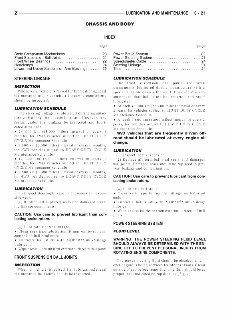
POWER STEERING SYSTEMFLUID LEVEL
WARNING: THE POWER STEERING FLUID LEVELSHOULD ALWAYS BE DETERMINED WITH THE EN-GINE OFF TO PREVENT PERSONAL INJURY FROM
ROTATING ENGINE COMPONENTS.
The power steering fluid should be checked when-
ever engine is being serviced for other reasons. C lean
outside of cap before removing. The fluid should be at
proper level indicated on cap dipstick (Fig. 2).
Z LUBRICATION AND M AINTENANCE 0 - 21

7/16/2019 ZJ Lube&Maintenance
http://slidepdf.com/reader/full/zj-lubemaintenance 22/24
Th e r e ser voir f luid level ca n be d e t er m in ed w it h
fluid either hot or cold. If f luid level is below FULL
H O T o r F U L L C O L D m a r k s o n d ip st ick , a d d p o w e r
st e er in g f luid . Th e d ipst ick is a t t a ch e d t o r e se r voir
cap (Fig. 2).
FLUID SPECIFICATION
Use only MOPARPower Steering Fluid.
FRONT WHEEL BEARINGSThe front w heel bearings on a ZJ vehicle are perma-
n en t l y l ub r ica t e d . I f s er v ice i s n eces s a r y r ef er t o
G roup 2—Front Su spension And Axle.
LOWER AND UPPER SUSPENSION ARM BUSH-INGS
INSPECTION SCHEDULE
Th e l ow e r a n d u pp er s u sp en s ion a r m b us h in g s
should be inspected each t ime underside of vehicle is
serviced.
INSPECTION
The lower suspension arm bushings can be visually
inspected by raising vehicle on a hoist and inspecting
f r om u n d er n e a t h . Th e u p pe r su spe n sion a r m bu sh -
ings can be inspected after removing front wheels. I f
f a il ur e ex is t s, r epl a ce b us h in g (r ef er t o G r ou p
2—Front Su spension for proper procedures).
The suspension arm bushings never should be
lubricated.
GUIDELINES
(1) F a u lt y bu sh in g s a r e d e t e ct e d by bu sh in g be in g
off-center in relation to outer sleeve.(2) Tota l failure is evident by excessive m ovement
within bushing.
(3) Small cracks in outer, non-confined rubber does
not indicat e fa ilure of rubber.
POWER BRAKE SYSTEMVe h icle s a r e e q u ip pe d w it h p ow e r d isc br a k e s a t
f r on t w h e e ls a n d d r u m br a k e s a t r e a r w h e els.
FLUID SPECIFICATION
P ow e r br a k e sy st e m s r e q u ir e MO PARHeavy-Duty
B r a k e F lu id.Th e u se o f a n e q u iva le n t p r od u ct id en t i f ie d w it h
FMVSS No. 116, DOT-3 an d SAE J -1703 S ta nda rd
designations is permissible.
U s e f r es h b r a k e f lu id on l y w h en a d d i ng f lu id t o
r e ser voir. N e ve r u se f lu id t h a t d oe s n o t con f or m t o
D O T/S AE S t a n d a r d s, or f luid f r om a con t a in e r t h a t
has been left open.
CAUTION: The use of a substandard brake fluid
could result in sudden brake failure during hard,
prolonged braking.
CAUTION: Do not allow petroleum base fluids to
contaminate brake fluid. Seal damage will result.
BRAKE FLUID LEVEL
ANTI-LOCK BRAKE SYSTEM
The anti-lock brake system fluid reservoir is located
in engine compartment at left side of dash panel.
(1) Clean cover before removing it.
Fig. 1 Steering Components—Typical
Fig. 2 Power Steering Reservoir & Cap—Typical
0 - 22 LUBRICATION AND M AINTENANCE Z

7/16/2019 ZJ Lube&Maintenance
http://slidepdf.com/reader/full/zj-lubemaintenance 23/24
CAUTION: Over-filling could cause fluid overflow
and possible reservoir damage when pump motor
energizes.
(2) T h e br a k e f lu id le ve l sh o u ld be n o lo w e r t h a n
MI N a r r o w in d ica t or on sid e of r e se r voir. I f n ot , a d d
br a k e f lu id a s n e ce ssa r y . Ra ise f lu id leve l t o MAX
arrow indicator only. Do not over-fill reservoir.
BRAKE SYSTEM INSPECTION
(1) I n sp ect br a k e p a d s a n d l in in g s f or e xcessive
wea r, cracks a nd broken rivets.
(2) I n sp e ct br a k e p a d s a n d l in in g s f o r co n t a m in a -
tion w ith brake fluid, a xle lubricant an d/or other flu-
ids.
(3) Replace front brake pads and rear brake liningsif t hey a re w orn t o wit hin 0.78 mm (1/32 in) of a rivet
h e a d .
(4) O per a t e r ea r b r a k e s el f-a d ju s t er l ev er a n d
pivot. Test opera tion of self-a djuster screw for eas e of
movement.
(5) I n sp ect se lf -a d ju st er com p on e n t s f or f r a y e d
cables. Inspect for loose or overheated springs, or a
binding condition.
(6) Inspect caliper dust boots for damage or tears.
I n sp e ct f o r a n in d ica t io n o f br a k e f lu id le a k a g e . I n -
sp ect bu sh in g s a n d p in s f or cor r osion . I n sp ect f or
tears or a binding condition.
(7) Inspect rear wheel cylinder dust boots for fluid
leaks. I nspect pistons an d cylinder bores for proper
appearance.
(8) I n s pe ct b r a k e d if fe re nt i a l w a r n i n g v a l ve a n d
housing for indications of leakage, kinked hoses and
loose fittings.
BRAKE HOSES/TUBING
The rubber brake hoses should be inspected for:
• Correct length
• Severe surfa ce cracking
• Swelling
• Pulling
• Scuffing
• Excessively worn areas
(1) Inspect all hoses for kinks, a distorted condition
and fluid leakage.
(2) Inspect hose and tubing routing under vehicle.
Ve ri fy t h a t n o h os e/t u b in g i s r u bb in g a g a i n s t a n y
underbody components.
PARK BRAKE
(1) Engage park brake lever and then release it .
(2) Te st p a r k in g br a k e f or sm oot h op er a t io n a n d
vehicle-holding capability.
(3) Inspect park brake cables for kinks, fraying and
a binding condition.
(4) Wit h p a r k br a k e r e le a sed , r e a r w h e els sh ou ld
r ot a t e w it h o u t r e st r ict ion . Ad ju st p a r k br a k e ca ble
t e n sion a t e q u a liz er. Re fe r t o G r ou p 5—B r a k e s, f o r
component information.
(5) Repair any park brake malfunctions.
BRAKE OPERATIONAL TEST
(1) Drive vehicle and test for proper bra ke action.
(2) Note any indicat ion of bra ke overheating, w heel
dragging or vehicle pulling to one side.
(3) Eva luate an y performa nce complaints received
from own er/operat or.
(4) R ep a i r b r a k e s y s t em a s n ece ss a r y (r ef er t o
G r ou p 5—B r a k es f or a d d it ion a l in for m a t ion a n d se r-
vice procedures).
BODY COMPONENT MECHANISMS
LUBRICATION REQUIREMENTS
All o p e r a t in g m e ch a n ism s a n d l in k a g e s sh o u ld be
lubricated when necessary. This will maintain ease of
op er a t i on a n d p rov id e p rot e ct i on a g a i n s t r u st a n d
e xce ssive w e a r. D o or w e a t h e r st r ip se a ls sh ou ld be
lu br ica t e d t o p r olon g t h e ir l i f e a s w e ll a s t o im p r ove
door sealing.
LUBRICANT SPECIFICATIONS
All applicable exterior and interior vehicle operat-
ing mechanisms should be:
• Inspected
• Cleaned
• All pivoting/sliding conta ct ar eas on mechan isms
should t hen be lubricat ed.
MOPARMulti-Mileage Lubricant or an equivalent,
sh ou ld be u sed t o lu br ica t e m e ch a n ism s. Th e d oor
weatherstrip seals should be lubricated with silicone
lu br ica n t sp r a y. Re fe r t o B o d y L u br ica n t S p ecif ica -
t i on s ch a r t b el ow f or a d d i t ion a l l ub r ica n t a p pl ica -
tions.
LUBRICATION
(1) When necessa ry, lubricat e body component op-
erating mechanisms with specified lubricants.
Fig. 3 Reservoir Fluid Level—Anti-Lock Brake Sys-
tem
Z LUBRICATION AND M AINTENANCE 0 - 23

7/16/2019 ZJ Lube&Maintenance
http://slidepdf.com/reader/full/zj-lubemaintenance 24/24
(2) Apply silicone lubrican t to a cloth. Wipe it on
door seals to avoid over-spray that can soil passenger
clothing.
(3) B efore a pplying lubricant , component should be
w ip ed cle a n . Af t e r lu br ica t io n , a n y e xcess lu br ica n t
should be removed.
(4) The hood latch, latch release mechanism, latch
striker and safety latch should be lubricated periodi-
cally.
(5) The door lock cylinders should be lubricated 2
times each year (preferably autumn and spring):
• S p r a y a s m a l l a m o un t of l ock cy l in d er l ub r ica n t
directly into lock cylinder
• Apply a small amount to key and insert it into lock
cylinder
• Ro t a t e i t t o lo ck e d p o sit io n a n d t h e n ba ck t o u n -
locked position several times• Re m ove k e y. Wipe lu br ica n t f r om i t w it h a cle a n
cloth to avoid soiling of clothing.
TIRES
RECOMMENDED MAINTENANCE
The condition of t ires should be inspected. The in-
f la t ion p r essu r es t e st ed /cor r e ct e d a t sa m e t im e a s
engine oil is changed a nd oil f ilter is replaced.
The t ires/wheels should be rotated periodically to
t d Th t i / h l h ld b
r ot a t e d a t f ir st 12 000 k m (7,500-m ile s) in t e r va l .
Thereaft er, a t each 24 000 km (15,000-miles) interva l.
INSPECTION
Inspect t ires for excessive w ear, da ma ge. Test t iresfor recommended inflat ion pressure. Refer t o G roup
22—Tires And Wheels for t ire pressure chart s, t ire
replacement, and treadwear indicators.
ROTATION
Tires/wh eels sh ould be rota ted a ccording to recom-
mended interval.
Refer to G roup 22—Tires And Wheels for recom-
mended meth od of tire/wh eel rotat ion.
HEADLAMPSEve r y six m o n t h s ch e ck h e a d la m p bea m s t o e n su r e
that headlamp beams are correctly posit ioned.
AIM ADJUSTMENT
R e f e r t o G r o u p 8 L — L a m p s f o r h e a d l a m p a i m a d -
justment procedures.
SPEEDOMETER CABLE
SERVICE INFORMATION
Speedometer cable lubricat ion is not necessary. For
service information involving noisy or erratic cables,
f t G 8E I t t P l d G g
BODY LUBRICANT SPECIFICATIONS
0 - 24 LUBRICATION AND M AINTENANCE Z