ZF28A TYPE GIS - Colproleccolprolec.com/wp-content/uploads/2017/11/Catalogo-145kV-GIS.pdf · 1...
12
-- . 1 ZF28A TYPE GIS (From 72.SkV to 145kV) GIS Address: Ningbo, China Tel: 0086-574-6526 9811 Website: www.tianan.com Address: Bogota, Colombia Tel: 0057-1-712 30 46 Website: www.colprolec.com ENERGY SOLUTIONS
-
Upload
vuongthien -
Category
Documents
-
view
230 -
download
1
Transcript of ZF28A TYPE GIS - Colproleccolprolec.com/wp-content/uploads/2017/11/Catalogo-145kV-GIS.pdf · 1...
--.
--
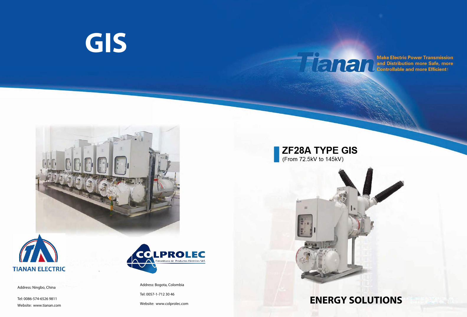
1 ZF28A TYPE GIS (From 72.SkV to 145kV)
GIS
Address: Ningbo, China
Tel: 0086-574-6526 9811
Website: www.tianan.com
Address: Bogota, Colombia
Tel: 0057-1-712 30 46
Website: www.colprolec.com ENERGY SOLUTIONS

Based on its R&D system and advanced research
abilities, TIANAN has become a well-known GIS
manufacturar in China. lts GIS technology has
reached the international advanced level.
Standard GIS Bay of ZF28A-72.5/126/145 Type
Single Bus Bar
Double Bus Bar
1. Local control cabinet2. Circuit breaker operating
mechanism3. Voltage transformar4. Fast earthing switch5. Three-position disconnector
and earthing switch6. Cable termination7. Cable Plug8. Current transformer9. Circuit breaker1 O. Three-position disconnector
and earthing switch 11. Surge arrester
Va/ue on Technology lnnovation, Seeking Continuous lmprovement
Advantages of ZF28A Series GIS (72.5kV-145kV) --=
11 Full three-phase encapsulated GIS, wíth a mínimum bay width of 800mm and standard bay width of 1000mm. Compact design, less requirement of land space. Avallability of whole bay transportation.
11 The temperatura risa type test was performed at 1.1 x rated current, thus the ability of GIS to withstand long lime rated curren! can be assured.
IIThe inspection and malntenance passages are arranged at two sidas of the bay, so lt is easier to enter into the bay during ínspection and maintenance.
Three- position DES are completely applied in GIS, realizing the slmplifled structure and rellable mechanlcal lockfng.
11 The partial discharge test is performed under 80% power frequency withstand voltage (80 ¾ x 275kV =220kV), whlch is far more strict than the voltage (1.2x145kV = 174kV) specified by IEC standard.
To lake advantage of simulation analysis and basic research on the intemal electric field, gas flow field and mechanical properties by the means of finite-element analysis software, the minimizing of the GIS dimension has been achieved.
• According to the factory quality control requirement, allbays are subject to perform power frequency withstandvoltage test, lightning impulse withstand test and partía!discharge test before delivery to site, so that the qualityof GIS can be assured.
11 Aluminum alloy enclosures are widely applied with advanced surface coating technology. Strict inspection on thickness and evenness of the surface coating ensures the antí-corrosion performance of the equlpment, and makes the equipment adapt to the severe environmental conditions.
a The product has performed low-temperature test in strict accordance with IEC standard.
-
Table of Contents
Circuit Breaker Module
Three-posltion disconnector and earthing switch
lnstrument transformer
Fast earthing switch and Surge arrester
Transitlon module and bus module
Terminal Elements
Basin-type lnsulator and SFg Gas System
Local control cabinel
Transportation. lnstallatlon, Maintenance and Service
Typical Layout
Main Technical Parameters
Quality Assurance
Performance
3
5
7
9
10
11
12
13
14
15
20
21

3
As the core component of GIS, the three-phase enclosed circuit breaker module consists of the vertical arcing chamber unit and the full-spring operating mechanism.
CI The circuit breaker adopts !he self-blast arcing principie. The self-blast arcing technology effectlvely reduces the operation power of !he operating mechanism and improves !he mechanical rellabillty of the product.
1 -�
Are quenching principie
Closed position
G lt has passed short-circuit current type test in KEMA, Netherlands.
G With the excellent performance ability, lhe circuit breaker is in Class E2-M2-C2.
lil The critica! insulating components such as insulating rod and insulating tube are importad from Switzer1and.
Opening High current breaking (15kA- 40kA) self-blast breaking technology.
� i] - ; �-
Low current breaking (<1 SkA) Gas compression breaking technology.
Are quenching Open posítlon
9 l ó 5 1 J !
1.Statie are contaet 2.Statie main contaet3. Nozzle 5.Moving main contaet 4,6.Moving are eontaet7.Cylinder 8.Statie piston 9.Rod
v1: Thermal expansion chamber v2: gascompress;ion chamber
Circuit breaker operating mechanism
1, The full-spring operating mechanism has a small volume and achieves 10,000 times of mechanical endurance.
G The operating mechanism base is made of casi alumlnum alloy and is produced through the precision machining in !he numerical control machining center of DMG four-shaft boring and milllng importad from Germany. Because of one-step molding by clamping machining, unified standard and minor machining error, !he assembly accuracy of !he operating mechanism canbe guaranteed.
G The mechanism is perfectly combinad with !he interrupter to achieve the outstanding performance of the circuit breaker. The closing spring and the opening sprlng are arranged at positions conveniently for observation.
13
12
11
10
9
a Due to our powerful baslc research ability, the spring is designad and produced according to the allowable stress which is lower than the testlng value, so as to ensure that the 10,000 llmes' life endurance can be achieved.
2
3
4
5
6
1. Motor2. Gear3. Closing main shaft
7 4.Small cam 5. Closlng buffer6. Transmission crank7. Opening buffer8. Opening sprtng9. Closing spring
8 10, Opening rod11. Closing rod12. Connectlng rod13. Cam

5
The disconnector and the maintenance earthing switch are combined with one moving contact shared. Because of the natural mechanical interlocking, the possibility that disconnector and earthing switch are simultaneously connected in the meantime is avoided and the risk of fault operation is completely avoided.
Bus three-position DES
G The bus three-position DES integrales the bus disconnector and maintenance earthing switch into the sama module, thereby realiza the direct connection for the bay and the interconnection between bays by branch bus and expansion joint.
G The bus three-position DES not only can switch the small capacitive curren! and small inductive curren!, but also can switch the bus -transfering curren! in the case of double-bus system.
G The humanizad structural design enabies the easy inspection of the opening/closing position from the overhaul patrol passage.
1. Movlng contact2. static contact of earthlng
switch3. Static contact of
dlsconnector4. Barrier insulator5. Expansion joint
Operating mechanism of DES
G The disconnector and maintenance earthing switch share one common operatíng mechanísm, and the operatíng mechanism can be manually operated in case of an emergency.
11 The mechanism is direcUy spllced onto the main body without connecling rod exposed, and it also has good transmission efficiency and good weather resistance.
11 Driven by double motor and mechanically intertocked, it has the clutch function.
Feeder three-position DES
G The feeder three-position DES is used for connection and disconnection inside feeders. it can be connected with various terminal modules (including cable terminal, overhead line and transformer terminal) and also can realíze the connection with voltage transformer and surge arrester.
1. Movtng contact
2. Static contact of earthlng switch
3. Statlc conlacl of dlsconnector
4. Barrier insulator
5. Supporting insulator
6. Cable terminal
G The feeder three-position DES Is installed In the module which realize the operatíon as follows.
Disconnector closed wilh earthing switch opened
Disconnector opened with earthing switch opened
Olsconnector opened with earthlng switch closed

7
Current transformer
The current transformer is used in GIS for current measurement and system protection.
a The electromagnetic curren! transformer is placed at the outlet side of the circuit breaker and is located in the same gas chamber as the circuit breaker.
D The secondary winding is casted by saturated epoxy resin, so its electric and mechanical strength is high and heat resistance is good.
a The windings use the polyester film with good moisture resistance as the interlayer insulating materials to strictly control the moisture.
• The secondary junction box adopts the casi aluminum structure, andthe secondary wiring board is casted by epoxy.
Solutions for intelligent GIS
Electronic combined transformer for GIS
D Digital output G Good electromagnetic compatlbllity 11 meets !he requirements of international standards and applles to the lntelllgent substation.
CI Low partial discharge The partial discharge is less than 5pC under 80% rated power frequency withstand voltage.
D Hiqh accuracy Curren! measurement leve!: 0.2S Curren! protection leve!: 5P or 5TPE Voltage measurement leve!: 0.2 Voltage protection leve!: 3P
G Wide operatinq temperatura ranqe Overall operating temperatura ranga of transformar: .3o·c-4s·c Operating temperature range of acquisition unit and combination unlt: -4o·c-as·c
lmmunlty level of voltage gradient +20%--20%
lmmunity level of voltago sag and short 0.1s for 50% sag and 0.05s
supply interruplion fer interruption
lmmunity level of surge (impact) Level 4
lmmunlty level of electrical fasl Level 4
1ransfont burst
lmmunlty leve! of oscíllatory wave Level 3
lmmunity levet of electrostatic Level 4
dlscharge
lmmunity leve! of power írequeocy Level 5
magnetic fleld
lmmunity level of pulsod magnot field Level 5
lmmunity levol of damped oscillatory Level 5
magnetic field
lmmunity levol of radiated Level 3
radioírequency electromagnetic field
Voltage transformer
The voltage transformer is used for voltage measurement and
system protection.
ll Each voltage transformer has its own independent gas chamber.
e;¡ The housing is welded by aluminum plate. Ali connecting bolts are the stainless steel parts and can be used outdoors. The base is installed with bursting disc. lf high-energy discharge occurs in the product, the bursting disc will be fractured to release the pressure and thus improve the product safety.
11 The secondary junction box adopts the cast aluminum structure, and the secondaJY wiring board is casted by epoxy.
11 The 1ransformer can be horizontally or vertically installed.

9
Fast earthing switch
lil The fast earthing switch is connected to the feeder three-position DES and shares one common gas chamber wíth DES.
G The fast earthing switch can switch the short-circuit curren! and inductiva curren!. The operating time of contact is less than 80ms, which is better than that required in IEC Standard.
e;¡ Electrlc sprlng operatlng mechanlsm
G The operating mechanism for fast earthing switch is the electric operating mechanism of charging sprfng type. lt also can be manually operated in case of an emergency.
G The transmission of energy storage process is simple, without extra intermediate link. The motor is decelerated by gear pair and is connected to the screw rod. The ball screw rod is used, so the transmission efficiency is high.
G The mechanism is directly connected without exposed connecting rod, so as to improve the transmission efficiency and enhance the weather resistance of products
Surge arrester
1. Moving contact2. StaUc contact
3. Connecting plate 4. Earthlng plate
As the protective element of GIS, the surge arrester is used for protecting the insulation of electrical equipment of GIS against the damage of lightning and operation impulse voltage.
a Surge arrester is mainly composed of enclosure, basin type insulator, mounting base and core body. The core body uses the zinc oxide resistor disc as the main element, with good volt-ampere characteristics. The resistor disc is connected into a cylindrical shape in series.
G The surge arrester is insulaled by SFs gas and is connected with GIS via intennediale flange. With standard connector, it is convenient for site inslallation.
11 Each surge arrester is equipped with online monitoring device to monitor the leakage of current and record the discharge frequency.
Metal bellows
G lt is made of stainless steel.
G lt is used for compensating the axial length change of bus caused by expansion and contraclion.
G lt is used for compensaling the conductor stress change caused by structural and installation errors.
Self-balanced bellows
11 lt Is made of stainless steel.
11 lts operating temperatura is -40'C-100'C and endurance lite is 11,000 times.
la lt can compensate the axial and radial conductor stress changas caused by foundatíon setUement. lts axial adjustment range is ±1 Smm, while its radial adjustment range is ±10mm.
Transition module
Aluminum alloy pipe adjustment joint
e; 11 is used for dismounting the faulty bay located in the middle part.
The transition module is used for realizing the interconnection inside the bay. The following severa! transition modules are available according to the space requirements for circuit design and alternative arrangement.
T-shaped module L-shaped module
Bushing bus module The bushing bus module is used for realizing the conversion of connection between three-phase module and slngle-phase module and is usually used for the connection between outlet module and bushing terminal.

11
Cable terminal
la Through the cable terminal module, GIS can be connected with various types of high voltage cables. The coordination between cable terminal box and cable terminal meets the requfrements of IEC 60859.
SFs/ air bushing
ca The connection between GIS and alr lnsulation equipment or overhead line is realizad by a comer module and a SFs/air bushlng. The air bushing is provided with traditional porcelain bushlng and sillcon rubber composíte bushing, to meet different usar requirements.
Cable terminal
CI The length, umbrella form and creepage distance of bushing can be designed according to insulation matching, minimum air insulation gap and pollution level. Through calculatlon and experi ental verification, the SFs/air bushing not only can provide best insulation ability , but also can ensure a longer service life.
Solutions for cold areas
a As for the system in the low-temperature areas at below -30"C, the bushing and the branch bus exposed outdoors adopt the independent gas chamber with gas filling pressure of 0.4MPa. lt has passed the type test and is applicable to the cold areas.
Solutions for coastal and heavy industry concentrated areas
ca The air bushing can be used in the coastal and heavy industry concentrated areas, and especially In the highly polluted areas, like thermal power plant, oil refinery, cement plant, chemical plant and coastal oil fields.
li The silicon rubber composlte bushing is recommended, which has good water resistance, strong anti-pollution flashover, high safety, and explosion and cracking protection.
Basin Type lnsulator
Metal flange and double-seal design
a Preven! the cracking of basin due to stress concentration of epoxy parts.
G Effectively prevent the aging of insulating materials due to ultraviolet rays and corrosiva gases, etc., and prolong the service lite of basln.
la Reduce the leakage of electromagnetic wave through overall shielding and reduce the radio lnterference.
la Preven! moisture from entering into the housing with outer sealing rlng. Preven! the leakage of SFs gas with inner sealing ring. the annual average gas leakage rata is lower than 0.3%.
a To ensure its quality, the tests including X-ray flaw detection, helium massspectrometer leak detection, high/low temperature test, hydraulic test, partial discharge measurement and power frequency withstand voltage test shall be performed in the factory.
SFs gas system
G The raw material of epoxy resin is importad from Switzerland.
G The basin type insulator, DES insulating rod, ES/ FES grounding base and CT secondary patching panel and other epoxy resin insulators are designed by the 145kV voltage class, with large insulation margin.
G The above insulators are casted by the Hübers vacuum mlxing epoxy casting equipment importad from Germany. The power frequency withstand voltage test and partlal discharge test are performed for each piece.
The design principie of SFs gas system is to abide by the execution functions of all equipment components.
G The basln type insulator is used for separatlng the GIS gas chamber.
G Each gas chamber is equipped with independenl gas monitoring device. The annual leakage rate of SFs gas is less than 0.3%.
D Each density relay is equipped with non-retum valve, so the relay can be checked without disassembly.
Feeder problem
85G
.
,¡,t.o
('H
m1 =.,.
:i,us l 11


15
For urban areas, populated areas, complex industrial areas and areas under harsh environmental conditions, GIS has its unique superiority.
Reasonable compact products
G Wlth modular design and standard connector, the product has good interchangeability between modules and is easy for extension.
G Wilh all-aluminum alloy housing, the product has small vortex loss. The standard bay is only 3 tons and is light in weight, so the civil cost is saved.
11 The standard bay is 1000mm wide. The depth of the plan! building required is generally 6.5m and the indoor height is generally 6m.
Typlcal dlmension dlagram
Cost saving for maintenance
m The connection between main bus of the bay is a dismountable structure, so overhauling maintenance is very easy.
Be applicable to various substation connection modes.
The optimal scheme design provides the combination form with highest cost performance for users.
Double-bus bar
D Toe double-busbar connection can shorten the power outage time, and make power supply more safe and reliable.
(E-01) (E-02)
©
1
@ ® ®
Layout diagram
(E<ll)
SSG
(E02)
SSG
Single line diagram
(E03) (Eo4) (EOS) (E08)
a, �r; � f11 !! � ® ® © ®
@ ® ®
� 1-i.. lo, -- - �SCF DE 8 A
(EOO) (E04) (EOS)
BSG
(E07) (8'8)
®
e 46000
(EOS)
®
(EO?)
6000
®
(EOS)
eso
A-A Eoi.'roe
D-D E05
� 5380
("jjW ll11J e-e F-F
Eo3 E04
�r- ªIrt E-E
•�1�

17
Single-bus connection
G The sectionalízed single-bus connectíon can enhance the relíabillty of power supply. lt Is simple and ís easy for extension wilh less investment.
Future extens!On
1
Layout diagram
FurureeitteMIOO 1eo1) 1e02)
BSG BSG
Single line diagram
(E011 iErol (E041 IE05i iEO?i
(E02i IE06)
i!, .!\ � s:, �A
..J ..J.., A 8 e
(Eo:u
..J..J .... C B A
¡eo•>
Fumre extension
-C·C
lE041
•
iEOS) (E061 1eo1) Future extenslon
BSG
-D·D IE05i
.dd,_ (E02i
_.
The optimal scheme design provides alternatives for users.
H circuit
11 Toe H circult saves floor area and requires less investment and is economical and practícal.
m m m
., J' .,
• Layout diagram
111
'
r
Single line diagram
Hl)I
""'
EO! lll
m
,. M:I lM IJI
.. J' ..
IU
"'
ltl
111[Mn;;h 1ffliLi

19
Li ne-transformer
The substation which has only one incomer and one transformer can adopts the line-transformation group connection. lt is convenient for operation and easy for extension with less investment.
Layout diagram
2# lncomer
BSG
GS
P2
G2 l TA
CB P1
DES1• G1
"FES1
G6
BSG
Single line diagram
1# lncomer
BSG
GS
G3
P2
G2 1 TA
CB P1
DES1· G1
.. FES1
G6
BSG
A-A-----... (E02)
A r
(E01) A r
Technical parameters
Rated Voltage 72.5kV /126kV /145kV
Rated Frequency 50Hz/60Hz
Rated Curren! 2000A/3150A
Phase to earth and between Phases
Rated Power Frequency 1 Min withstand Voltage Across the isolating distance
Phase to earth and between Phases Rated Lightning impulse withstand Voltage
Across the isolating distance
Test voltage
Partial Discharge Whole bay
lnsulator
Rated Short Circuit Breaking Curren!
Rated Peak withstand Current
Rated Short Duration withstand Curren!
Rated Pressure
Circuit Breaker Compartment Alarm Pressure
SFs Gas Pressure Lockout Pressure
(at 20º C,Absolute Rated Pressure
Pressure) Other Compartments Alarm Pressure
Lockout Pressure
Circuit Breaker Compartment Commissioning
Moisture Content Operation
of SF6 Gas Commissioning Other Compartments
Operation
SFs Gas Leakage Rate
Breaking times of rated short circuit breaking curren! of circuit breaker (Electrical Endurance)
Mechanical Circuit Breaker
Endurance Disconnector and earthing switch (DES)
Service Life
Maintenance Cycle
Making times of Rated Short Circuit Making Current (FES)
Structure
Standard Dimension (Width x Depth x Height)
275kV
275kV+84kV
650kV
650kV+118kV
220kV
5pC
3pC
40kA
50Hz: 100kA 60Hz: 104kA
40kA/4s
0.68MPa
0.63MPa
0.60MPa
0.68MPa
0.63MPa
0.60MPa
150ppm(uUL)
300ppm(uUL)
250ppm(uUL)
500ppm(uUL)
:S:0.5% per year
20 times
10000 times
10000 times
�30 years
�o years
Twice
Three Phase encapsulated
800x4270x3003mm