zeus KNURLING TECHNOLOGY - oclmexico.com · zeus® knurling technology--> knurling wheels--> form...
64
zeus ® KNURLING TECHNOLOGY --> KNURLING WHEELS --> FORM KNURLING TOOLS --> CUT KNURLING TOOLS --> SPECIAL TOOLS
Transcript of zeus KNURLING TECHNOLOGY - oclmexico.com · zeus® knurling technology--> knurling wheels--> form...

zeus® KNURLING TECHNOLOGY
--> KNURLING WHEELS
--> FORM KNURLING TOOLS
--> CUT KNURLING TOOLS
--> SPECIAL TOOLS

We work with enthusiasm for your satisfaction:From innovative products, like the new RF1- LD generation, to the qualified advice and application support.
2
TECHNOLOGY. SERVICE. PASSION.
WELCOME TO HOMMEL+KELLER PRÄZISIONSWERKZEUGE!

YOUR SUCCESS FACTORS:
--> APPLICATION-ORIENTED
PRODUCT RANGE WITH PERFECT
FUNCTIONALITY
--> EXCELLENT VISUAL PROFILES
--> FIRST-CLASS SURFACE QUALITY
--> LEADING KNURLING
TECHNOLOGY FOR HIGH-END
PRODUCTS
High quality standards towards consumer and industrial goods, especially in the premium segment, call for exceptional precision and surface quality of the knurling profile. Premium products require only too often a customized tool solution. As a result they stand out with a significant difference regarding visual and functional features compared to low-end products.
Hommel + Keller exceeds all of these expectations in every aspect with the premium brand zeus®. Individual product solutions bring forth superior final products, as for example control panels for the automotive industry or jewellery for the watch making industry.
Perfect precision, excellent visual appearance and first-class sur-face quality are the performance parameters for a superior knurling profile. zeus® knurling tools offer the decisive advance for your success.
Our mission is simple:We will exceed the expectations of our customers with innovative, application-oriented tools and customer-oriented service offerings.
Experience performance by pas-sion: zeus® Knurling Technology.
Welcome!
3

CONTENT
--> Company .................................................... Page 02 - 03
--> Applications .............................................. Page 05
--> Tool choice ................................................ Page 06 - 07
--> Machine types/ Tool characteristics ................................ Page 08 - 09
--> Application techniques .......................... Page 10 - 13
--> Form knurling tools ................................ Page 14 - 31
--> Cut knurling tools ................................... Page 32 - 41
--> Special tools ............................................. Page 42 - 44
--> Knurling wheels ....................................... Page 45 - 54
--> Burnishing Rolls ....................................... Page 55
--> Marking Rolls/ Engraving Technology ............................ Page 56
--> Technical appendix ................................. Page 57 - 63
4
TABLE OF CONTENTS

Our product programme offers tool solutions for manifold requirements of the knurling technique. zeus® knurling tools are suited to produce standard profiles according to DIN standard, as well as conical, convex, concave and special profiles (e.g. E, C profiles). The application example below shows the multitude of application possibilities that can be covered with a zeus® knurling tool.
Application Profile (DIN 82) Tool Knurling Pitch wheels
Cut knurling RGE30° 291 3 x AA (Axial) 0,8
Cut knurling RGE45° 241 1 x BL15° (Axial) 0,6 1 x BR15°
Cut knurling RAA 231 1 x BR30° (Axial) 1,0
Form knurling RKE 131 1 x KV (Radial) 0,8 Form knurling RKV 132 1 x KE (Radial) 0,6
Form knurling RGE45° 141 1 x BL45° (Radial) 0,8 1 x BR45°
Form knurling RAA 132 1 x AA (Radial + Axial) 1,0 Knurling to a shoulder
Form knurling (Radial) RHV 131 1 x HE
Form knurling (Radial) RE 131 1 x C
Form knurling (Radial) RC 131 1 x E
Form knurling RKAA 311 1 x KAA (Radial + Axial)
Form knurling (Axial) RAA-plane 311 AA
Marking conical 123 312 40W
Marking revolving zeus® 130 40W
Marking spring-back hommel-keller.de 431 41W
Marking plane XYZ 311 40W
APPLICATION EXAMPLE:
(not visible)
5
APPLICATIONS
x
x
x
Work piece
Work piece
RAA-Knurl with straight pattern
RBL-Knurl, left-hand spiral
RGE-Diamond knurl, left-/right-hand knurl, points raised (male), 30°
RGV-Diamond knurl, left-/right-hand knurl, points indented (female), 30°
RKE-Cross-knurl, points raised (male), 90°
RKV-Cross-knurl, points indented (female), 90°
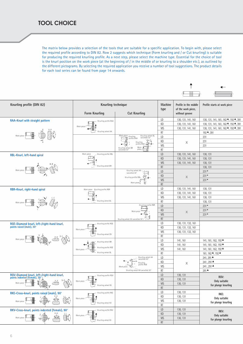
Knurling profile (DIN 82) Knurling technique Machine Profile in the middle Profile starts at work piece type of the work piece, Form Knurling Cut Knurling without groove
LD 130, 131, 141, 161 130, 131, 141, 161, 162▲, 192▲, 391 KD 130, 131, 141, 161 130, 131, 141, 161, 162▲, 192▲, 391 MS 130, 131, 141, 161 130, 131, 141, 161, 162▲, 192▲, 391 RT 192▲, 391 LD 231
KD 231
MS 231
RT LD 130, 131, 141, 161 130, 131 KD 130, 131, 141, 161 130, 131 MS 130, 131, 141, 161 130, 131 RT 130, 131 LD 231 * KD 231 * MS 231 * RT LD 130, 131, 141, 161 130, 131 KD 130, 131, 141, 161 130, 131 MS 130, 131, 141, 161 130, 131 RT 130, 131 LD 231 * KD 231 * MS 231 * RT LD 130, 131, 132, 161 KD 130, 131, 132, 161 MS 130, 131, 132, 161 RT LD 141, 161 141, 161, 162, 192▲
KD 141, 161 141, 161, 162, 192▲
MS 141, 161 141, 161, 162, 192▲
RT 161, 162▲, 192▲
LD 241, 291▲
KD 241 , 291▲
MS 241 , 291▲
RT 291▲
LD 130, 131 KD 130, 131 MS 130, 131 RT LD 130, 131 KD 130, 131 MS 130, 131 RT LD 130, 131 KD 130, 131 MS 130, 131 RT
Work piece
Knurling profile RBL
Knurling wheel AA swivelled 30°
Knurling wheel AA swivelled 30°
Knurling profile RBR
Work piece
Work piece
Knurling profile RGE
Knurling wheel AA swivelled 30°
Knurling wheel AA swivelled 30°
Knurling wheel BR swivelled 30°
Work piece
Knurling profile RAA
Knurling wheel BL swivelled 30°
Workpiece
Knurling profile RAA
Work piece
Knurling profile RAA
Knurling wheel AA
Work piece Knurling profile RBR
Knurling wheel BL
Knurling profile RGE
Knurling wheel GV
Work piece
Knurling profile RGE
Knurling wheel BL
Knurling wheel BR
Work piece
Knurling profile RGV
Knurling wheel GE
Work piece
Work piece
Knurling wheel KV
Knurling profile RKE
Work piece
Knurling wheel KE
Knurling profile RKV
Work piece Knurling profile RBL
Knurling wheel BR
RKV:Only suitable
for plunge knurling
RKE:Only suitable
for plunge knurling
RGV:Only suitable
for plunge knurlingWork piece
Work piece
Work piece
Work piece
Work piece
RBR-Knurl, right-hand spiral
The matrix below provides a selection of the tools that are suitable for a specific application. To begin with, please select the required profile according to DIN 82. Row 2 suggests which technique (Form knurling and / or Cut knurling) is suitable for producing the required knurling profile. As a next step, please select the machine type. Essential for the choice of tool is the knurl position on the work piece (at the beginning of / in the middle of or knurling to a shoulder etc.), as outlined by the different pictograms. By selecting the required application you receive a number of tool suggestions. The product details for each tool series can be found from page 14 onwards.
x
6
TOOL CHOICE

x
x
x x
x x
x x x x x
x x x x x
x x x x
x x x x
Profile starts in the Profile starts in the Knurling to a shoulder Profile starts at work Conical knurling profile Face knurling Knurling withinmiddle of the work middle of the work piece, knurling to a a borepiece, after a groove piece, without a groove shoulder
130, 131, 141, 161 130, 131, 141, 161 132, 142 132, 142, 162▲, 192▲ 311, 312 311, 312 330, 332130, 131, 141, 161 130, 131, 141, 161 132, 142 132, 142, 162▲, 192▲ 311, 312 311, 312 330, 332130, 131, 141, 161 130, 131, 141, 161 132, 142 132, 142, 162▲, 192▲ 311, 312 311, 312 330, 332 162▲, 192▲ 330, 332231231231
130, 131, 141, 161 130, 131, 141, 161 132, 142 132, 142, 162▲, 192▲ 311, 312 311, 312 330, 332130, 131, 141, 161 130, 131, 141, 161 132, 142 132, 142, 162▲, 192▲ 311, 312 311, 312 330, 332130, 131, 141, 161 130, 131, 141, 161 132, 142 132, 142, 162▲, 192▲ 311, 312 311, 312 330, 332 162▲, 192▲ 231 *231 *231 *
130, 131, 141, 161 130, 131, 141, 161 132, 142 132, 142, 162▲, 192▲ 311, 312 311, 312 330, 332130, 131, 141, 161 130, 131, 141, 161 132, 142 132, 142, 162▲, 192▲ 311, 312 311, 312 330, 332130, 131, 141, 161 130, 131, 141, 161 132, 142 132, 142, 162▲, 192▲ 311, 312 311, 312 330, 332 162▲, 192▲ 231 *231 *231 *
132 132 311, 312 311, 312 330, 332 132 132 311, 312 311, 312 330, 332 132 132 311, 312 311, 312 330, 332 162▲ 141, 161 141, 161 142 141, 162▲, 192▲ 340, 342141, 161 141, 161 142 141, 162▲, 192▲ 340, 342141, 161 141, 161 142 141, 162▲, 192▲ 340, 342 162▲, 192▲
241241241 132 311, 312 311, 312 330, 332 132 311, 312 311, 312 330, 332 132 311, 312 311, 312 330, 332 311, 312 330, 332 132 330, 332 132 330, 332 132 330, 332 330, 332 132 330, 332 132 330, 332 132 330, 332 330, 332
//
RKV:Only suitable
for plunge knurling
RKE:Only suitable
for plunge knurling
RGV:Only suitable
for plunge knurling
RKV:Only suitable
for plunge knurling
RKE:Only suitable
for plunge knurling
RGV:Only suitable
for plunge knurling
RKV:Only suitable
for plunge knurling
RKE:Only suitable
for plunge knurling
RGV:Only suitable
for plunge knurling
EXPLANATION OF AROWS:
EXAMPLE: SYMBOLS:
Profile can only be produced in radial tool direction (plunge knurling)Profile can only be produced in axial tool direction (feed knurling)Profile can be produced in axial and radial tool direction
LD = Swiss type autolathesKD = Automatic short-turning lathes, Universal lathes, Turning-/milling centreMS = Multispindle automatic lathesRT = Rotary indexing machines / Indexing table machines / Automatic transfer machines x = Cut knurling not possible for this application (see also p.13) ▲ = Limited length of knurling profile * = When cut knurling the manufacture of RBR/RBL profiles is restricted
Knurling profile
Only suitablefor plunge knurling
7

Machine types Distinctive features according to machine characteristics
Swiss type autolathes
Automatic short-turning lathes /Universal lathes /Turning-/milling centre
Multispindle automatic lathes
Rotary indexing machine /Indexing table type machine /Transfer machine
LD
KD
MS
RT
Tool fitting in:• Long slide• Cross slide• Turret
Tool fitting in:• Long slide• Cross slide• Turret
Tool fitting in:• Long slide• Cross slide• Support of an
automatic lathe
Tool fitting in:• Spindle nose unit
CNC
Conventional
CNC
Conventional
CNC
Conventional
Right-hand turningLeft-hand turning
Direction of rotation universal
Right-hand turningLeft-hand turning
Direction of rotationuniversal
Right-hand turningLeft-hand turning
Direction of rotationuniversal
Tool rotatingWork piece fixDirection of rotationuniversal
8
MACHINE TYPES
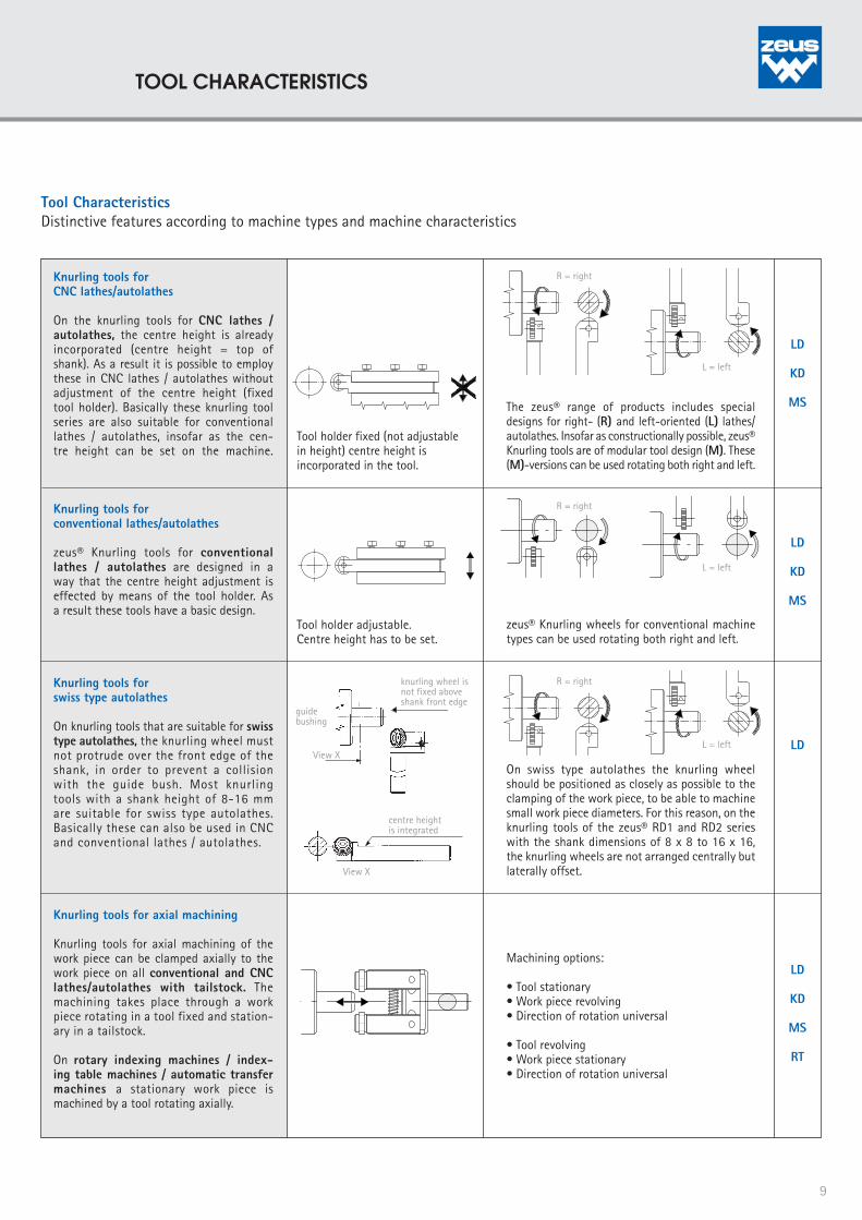
Tool Characteristics Distinctive features according to machine types and machine characteristics
Tool holder fixed (not adjustable in height) centre height is incorporated in the tool.
Tool holder adjustable.Centre height has to be set.
LD
KD
MS
LD
KD
MS
LD
LD
KD
MS
RT
L = left
L = left
R = right
L = left
R = right
R = right
The zeus® range of products includes special designs for right- (R) and left-oriented (L) lathes/autolathes. Insofar as constructionally possible, zeus® Knurling tools are of modular tool design (M). These (M)-versions can be used rotating both right and left.
zeus® Knurling wheels for conventional machine types can be used rotating both right and left.
On swiss type autolathes the knurling wheel should be positioned as closely as possible to the clamping of the work piece, to be able to machine small work piece diameters. For this reason, on the knurling tools of the zeus® RD1 and RD2 series with the shank dimensions of 8 x 8 to 16 x 16, the knurling wheels are not arranged centrally but laterally offset.
Machining options:
• Tool stationary• Work piece revolving• Direction of rotation universal
• Tool revolving• Work piece stationary• Direction of rotation universal
knurling wheel isnot fixed aboveshank front edge
guidebushing
View X
centre heightis integrated
View X
Knurling tools forCNC lathes/autolathes
On the knurling tools for CNC lathes / autolathes, the centre height is already incorporated (centre height = top of shank). As a result it is possible to employ these in CNC lathes / autolathes without adjustment of the centre height (fixed tool holder). Basically these knurling tool series are also suitable for conventional lathes / autolathes, insofar as the cen-tre height can be set on the machine.
Knurling tools forconventional lathes/autolathes
zeus® Knurling tools for conventional lathes / autolathes are designed in a way that the centre height adjustment is effected by means of the tool holder. As a result these tools have a basic design.
Knurling tools forswiss type autolathes
On knurling tools that are suitable for swiss type autolathes, the knurling wheel must not protrude over the front edge of the shank, in order to prevent a collision with the guide bush. Most knurling tools with a shank height of 8-16 mm are suitable for swiss type autolathes. Basically these can also be used in CNC and conventional lathes / autolathes.
Knurling tools for axial machining
Knurling tools for axial machining of the work piece can be clamped axially to the work piece on all conventional and CNC lathes/autolathes with tailstock. The machining takes place through a work piece rotating in a tool fixed and station-ary in a tailstock.
On rotary indexing machines / index-ing table machines / automatic transfer machines a stationary work piece is machined by a tool rotating axially.
9
TOOL CHARACTERISTICS

APPLICATION TECHNIQUES
CONTENT
KNURLING TECHNIQUES
APPLICATION CHARACTERISTICSFORM KNURLING
APPLICATION CHARACTERISTICSCUT KNURLING
10

In knurling technology two different application techniques can be distinguished: Cut Knurling and Form Knurling. Both techniques have their own characteristics, range of applications, advantages and limitations. Whereas one advantage of form knurling is the easy tool handling, cut knurling is always the preferred method whenever the surface quality requires uncompromising precision. On the following pages, the different attributes, the range of applications, their advantages and limitations are summarized.
A fundamental distinction lies in the relation between tool direction and possible knurling profiles. The chart below outlines this important distinction:
KNURLING TECHNIQUES
Form KnurlingWithout swarf
removal
Plunge and Feed KnurlingRadial and axialtool direction
Feed Knurling Axial
tool direction
Plunge KnurlingRadial
tool direction
Feed KnurlingAxial
tool direction
Cut KnurlingSwarf
removal
RAA
RBLRBR
RGE
RAA
RBLRBR
RAA
RBLRBR
RAA
RBLRBR
RGE RGE* RGE*RGV
RKE RKV
POSSIBLE KNURLING PROFILES
* Only suitable with knurling tools RD2/RD3/RF2/RF3
11
KNURLING TECHNIQUES
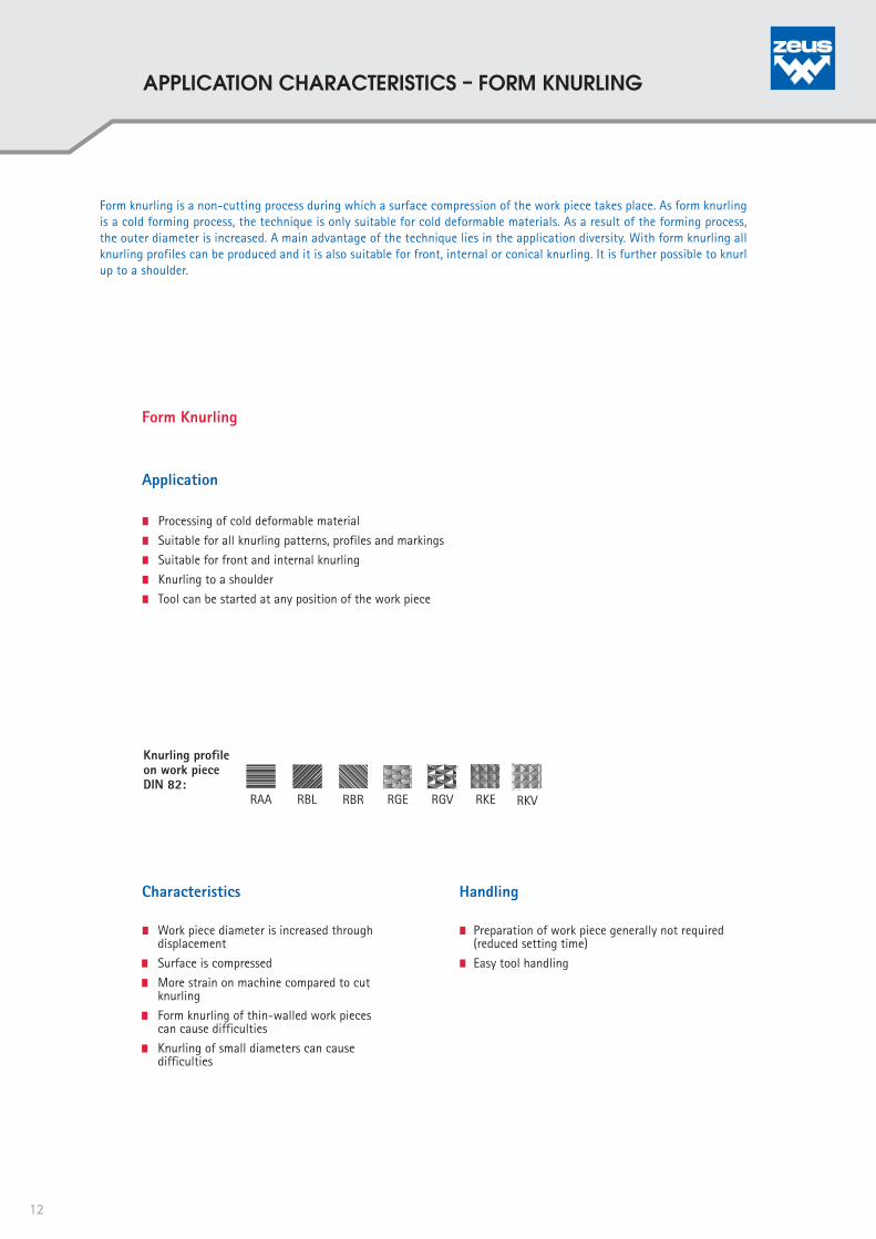
Form knurling is a non-cutting process during which a surface compression of the work piece takes place. As form knurling is a cold forming process, the technique is only suitable for cold deformable materials. As a result of the forming process, the outer diameter is increased. A main advantage of the technique lies in the application diversity. With form knurling all knurling profiles can be produced and it is also suitable for front, internal or conical knurling. It is further possible to knurl up to a shoulder.
Form Knurling
RAA RBL RBR RGE RGV RKE RKV
Knurling profile on work piece DIN 82:
Processing of cold deformable material
Suitable for all knurling patterns, profiles and markings
Suitable for front and internal knurling
Knurling to a shoulder
Tool can be started at any position of the work piece
Application
Characteristics Handling
Preparation of work piece generally not required (reduced setting time)
Easy tool handling
Work piece diameter is increased through displacement
Surface is compressed
More strain on machine compared to cut knurling
Form knurling of thin-walled work pieces can cause difficulties
Knurling of small diameters can cause difficulties
12
APPLICATION CHARACTERISTICS – FORM KNURLING

Cut knurling is the milling alternative to form knurling. During feed, material is removed. This technique is especially suitable for thin-walled work pieces, soft materials (e.g. plastics) or difficult to machine materials. Cut knurling excels in high precision and excellent surface quality, a reason why it is recommended for producing high-quality visual profiles. Contrary to form knurling, the surface compression and the material displacement are negligible. The strain on the machine is also relatively small. One major restriction of the cut knurling technique is the smaller range of application. Cut knurling is only suitable for producing the knurling profiles RAA and RGE. Furthermore, due to the minimal surface compression, the toughness of the knurling profile is reduced.
Cut Knurling
RAA RBL* RBR* RGE
Knurling profile on work piece DIN 82:
Suitable for most materials
Suitable for thin-walled work pieces
Suitable for very small work pieces
High precision and surface quality, therefore suitable for excellent visual profiles
Limited range of application: The knurling profiles RAA and RGE can be produced with all tool series. The possibility of the knurling profiles RBR and RBL is limited
Only suitable for cylindrical work pieces in axial tool direction
Knurling to be started at work piece end or in the middle after a groove
Knurling up to a shoulder is not possible
Application
Characteristics Handling
Precise setting of tool and fine adjustment required
Precise setting of work piece required
No major change in diameter after knurling
Minimal surface compression
Less strain on machine compared to form knurling
Minimal strain on tool and work piece
* With cut knurling, the manufacture of the knurling profiles RBR and RBL is subject to restriction.
13
APPLICATION CHARACTERISTICS – CUT KNURLING

CONTENT
FORM KNURLING TOOLS:RD1, RD2, RD3
CUT KNURLING TOOLS:RF1, RF2, RF3
SPECIAL TOOLS
FORM KNURLING TOOLSCUT KNURLING TOOLSSPECIAL TOOLS
14

APPLICATION EXAMPLE:
Bushing
APPLICATION:
Material: Cu2n38Pb2Knurling Profile/Pitch(DIN 82): RGE45°/P. 0,6Machine: Traub TD 60No. of pcs. produced/ knurling wheel: 150.000
APPLICATION PARAMETERS zeus® RD1:
Knurling tool: 130-12U250606 Knurling wheel: GV45°20x6x6, P. 0,6Cycle time: 0,8 sec/pieceSpeed rate: 240 m/minFeed rate: 0,2 mm/revTool life knurling wheel: 2000 (min/knurling wheel)Performance: 18,378 m²/knurling wheel
MODULAR PRODUCT DESIGN:
Modular shank system for cost-effective use on all CNC- / and cam- controlled swiss type auto-lathes
EASY TOOL HANDLING:
Easy application and tool handling Minimal work piece preparation Integrated set screws for easy
adjustment of the clearance angle Click-pin® versions for still faster
and safer change of knurling wheels
HIGH WEAR RESISTANCE:
Special surface hardening for increased tool life
Carbide pins for higher speed rates, faster production, prolonged life
APPLICATION ADVANTAGES:
The zeus® RD1 series for form knurling applications is the economic and easy solution for producing all kinds of knurling profiles. A classic, that can also be used for the marking of work pieces on autolathes. A further advantage: The knurling profile can start at any position of the work piece – a groove is not required.
MODULAR PRODUCT DESIGN CLICK-PIN®-SYSTEM
For fast and safe change of the knurling wheel:
--> No more break off through overtightening--> No more loosening through impact, hits or vibration--> Quick change and positioning of the knurling wheel
KNURLING TO SHOULDER
Tool types for knurling to shoulder:For swiss type autolathe versions:
15
zeus® FORM KNURLING TOOLS RD1

zeus® FORM KNURLING TOOL 130:
THE CLASSIC WITH ONE KNURLING WHEEL – CONVINCING EFFICIENCY FOR CONVENTIONAL AUTOLATHES!
ORDER EXAMPLE:
Product seriesShank size 16 x 16 mmRight-/ and left- hand use
For knurling wheels 25 x 8 x 6 (Ø x width x bore)
Tool holder No. 130-16 U 250806-AModel A
TOOL TYPES:
Tool holder Working area a b c d e f x Knurling Spare part No. Ø mm mm mm mm mm mm mm mm wheels mm Pin width Ø 15 width Ø 15 width Ø 15 (Ø x width x bore)
width Ø 25 width Ø 25 width Ø 25 130-08U150404-A 3-20 8 8 99 10 19 10 4 10 / 15 x 4 x 4 06TER0972 130-08U150604-A 3-20 8 8 99 14 19 10 4 10 / 15 x 6 x 4 06TER0974 130-10U150404-A 3-20 10 10 99 10 - 10 4 10 / 15 x 4 x 4 06TER0972 130-10U150604-A 3-20 10 10 99 14 19 10 4 10 / 15 x 6 x 4 06TER0974 130-10U250806-A 15-200 10 10 110,5 16 30,5 16 5,5 20 / 25 x 8 x 6 06TER0980 130-12U150404-A 3-20 12 12 99 12 - 12 4 10 / 15 x 4 x 4 06TER0973 130-12U250606-A 15-200 12 12 110,5 14 30,5 14 5,5 20 / 25 x 6 x 6 06TER0979 130-12U250806-A 15-200 12 12 110,5 16 30,5 16 5,5 20 / 25 x 8 x 6 06TER0980 130-14U150604-A 3-20 14 14 99 14 - 14 4 10 / 15 x 6 x 4 06TER0974 130-14U250606-A 15-200 14 14 110,5 14 - 14 5,5 20 / 25 x 6 x 6 06TER0979 130-16U250806-A 15-200 16 16 110,5 16 - 16 5,5 20 / 25 x 8 x 6 06TER0980 130-20U251006-A 15-200 20 20 110,5 20 - 20 5,5 20 / 25 x 10 x 6 06TER0982 130-20U251506-A 15-200 20 25 110,5 25 - 20 5,5 20 / 25 x 15 x 6 06TER0983
Tool holder Working area a b c d e f x Knurling Spare part No. Ø mm inch inch/ mm mm mm mm mm wheels inch Pin mm (Ø x width x bore) 130-70U515318-A 3-20 5⁄16 5⁄16 96 10 16 10 1 5/16 x 5/32 x 1/8 06TER0985 130-75U123131-A 3-20 1⁄2 1⁄2 96,3 12,7 - 12,7 1,3 1/2 x 3/16 x 3/16 06TER0986 130-80U581414-A 3-20 5⁄8 5⁄8 107 15,8 - 15,8 2 5/8 x 1/4 x 1/4 06TER0988 130-85U343814-A 15-200 3⁄4 3⁄4 108 19,05 - 19,05 3 3/4 x 3/8 x 1/4 06TER0970 130-90U343814-A 15-200 3⁄4 20 mm 111 20 - 25,4 6 3/4 x 3/8 x 1/4 06TER0970
Carbide pin
Carbide pin
f a
d
e
x
c
b
ab
c
x
Machine type: Conventional and CNC – suitable for: • Lathe / autolathes • Swiss type autolathes • Automatic short-turning lathes • Multispindle automatic lathesApplication: Form knurling (non-cutting forming) Knurling profileon work piece DIN 82: RAA RBL RBR RGE RGV RKE RKVKnurlingwheels: AA BR BL GV GE KV KETool • Plunge knurling: Suitable for all knurling profiles,direction: patterns and markings • Feed knurling: Suitable for RAA, RBL, RBRProduct • Centre height adjustablehighlights: • Integrated set screws for easy adjustment of the clearance angle • Carbide pins • Special surface hardening for increased wear resistance
16
zeus® Form Knurling Tools RD1

zeus® FORM KNURLING TOOL 131:
THE CLASSIC WITH ONE KNURLING WHEEL – CONVINCING EFFICIENCY FOR SWISS TYPE AUTOLATHES!
CLICK-PIN®-SYSTEM: For fast and safe change of the knurling wheel:
--> No more break off through overtightening--> No more loosening through impact, hits
or vibration--> Quick change and positioning of the
knurling wheel
Shank size Part-No.10 x 10 21BHR083312 x 12 21BHR083416 x 16 21BHR0835
SHANK ADAPTORS:
Modular shank construction for conversion to alternative shank sizes
Machine type: Conventional and CNC – suitable for: • Swiss type autolathes
Application: Form knurling (non-cutting forming)
Knurling profileon work piece DIN 82: RAA RBL RBR RGE RGV RKE RKV
KnurlingKnurling wheel: AA BR BL GV GE KV KE
Tool • Plunge knurling: Suitable for all knurling profiles,direction: patterns and markings • Feed knurling: Suitable for RAA, RBL, RBR
Product • Modular shank construction for conversion to alternative highlights: shank sizes • Integrated set screws for easy adjustment of the clearance angle • Carbide pins • Special surface hardening for increased wear resistance
06TER1015
06TER0960
TOOL TYPES:
ORDER EXAMPLE:
Product seriesShank size 10 x 10 mmLeft-hand use
For knurling wheels 10 x 3 x 6 (Ø x width x bore)
Tool holder No. 131 -10 L 100306 - A (-Z)Model A
with ClickPin®
Right Left
Tool holder Working area a b c* d e* f x* Knurling wheels Spare part No. Ø mm mm mm mm mm mm mm mm mm (Ø x width x bore) Pin
131-08L150404-A 3-50 8 8 99 12 19 18 4 10/15 x 4 x 4 06TER0960 131-08R150404-A 3-50 8 8 99 12 19 18 4 10/15 x 4 x 4 06TER0960 131-10L150404-A 3-50 10 10 99 12 19 20 4 10/15 x 4 x 4 06TER0960 131-10R150404-A 3-50 10 10 99 12 19 20 4 10/15 x 4 x 4 06TER0960 131-12L150404-A 3-50 12 12 99 12 19 22 4 10/15 x 4 x 4 06TER0960 131-12R150404-A 3-50 12 12 99 12 19 22 4 10/15 x 4 x 4 06TER0960 131-16L150404-A 3-50 16 16 99 12 19 26 4 10/15 x 4 x 4 06TER0960 131-16R150404-A 3-50 16 16 99 12 19 26 4 10/15 x 4 x 4 06TER0960
Mit ClickPin®: 131-08L150404-A-Z 3-50 8 8 99 12 19 18 4 10/15 x 4 x 4 06TER1015 131-08R150404-A-Z 3-50 8 8 99 12 19 18 4 10/15 x 4 x 4 06TER1015 131-10L150404-A-Z 3-50 10 10 99 12 19 20 4 10/15 x 4 x 4 06TER1015 131-10R150404-A-Z 3-50 10 10 99 12 19 20 4 10/15 x 4 x 4 06TER1015 131-12L150404-A-Z 3-50 12 12 99 12 19 22 4 10/15 x 4 x 4 06TER1015 131-12R150404-A-Z 3-50 12 12 99 12 19 22 4 10/15 x 4 x 4 06TER1015 131-16L150404-A-Z 3-50 16 16 99 12 19 26 4 10/15 x 4 x 4 06TER1015 131-16R150404-A-Z 3-50 16 16 99 12 19 26 4 10/15 x 4 x 4 06TER1015
* width Ø15cc
e
x
fd
2
ab d
f
e
x
2
ba
17
zeus® Form Knurling Tools RD1

with ClickPin®
zeus® FORM KNURLING TOOL 131:
THE CLASSIC WITH ONE KNURLING WHEEL – CONVINCING EFFICIENCY FOR CNC -AUTOLATHES!
Machine type: Conventional and CNC – suitable for: • Automatic short-turning lathes, Universal lathes, Turning- / milling centre • Multispindle automatic lathes
Application: Form knurling (non-cutting forming)
Knurling profileon work piece DIN 82: RAA RBL RBR RGE RGV RKE RKV
Knurlingwheels: AA BR BL GV GE KV KE
Tool • Plunge knurling: Suitable for all knurling profiles, direction: patterns and markings • Feed knurling: Suitable for RAA, RBL, RBR
Product • Integrated set screws for easy adjustment of the clearance anglehighlights: • Carbide pins • Special surface hardening for increased wear resistance
Tool holder Working area a b c e f x Knurling wheels Spare part No. Ø mm inch mm mm mm mm mm mm (Ø x width x bore) Pin
131-85U343814-A 8-200 3/4" 20 116,5 24,5 29 2,5 3/4" x 3/8" x 1/4" 06TER0989 131-90U343814-A 8-200 1" 20 116,5 24,5 35 2,5 3/4" x 3/8" x 1/4" 06TER0989
06TER0965/06TER0989
06TER1018
Tool holder Working area a b c mm e mm f mm x mm Knurling wheels Spare part No. Ø mm mm mm width Ø 25 width Ø 25 width Ø 25 width Ø 25 mm (Ø x width x bore) Pin
131-20U250806-A 8-200 20 20 109,5 29,5 32,5 5,5 20 / 25 x 8 x 6 06TER0965 131-25U250806-A 8-200 25 20 109,5 29,5 37,5 5,5 20 / 25 x 8 x 6 06TER0965 With ClickPin®: 131-20U250806-A-Z 8-200 20 20 109,5 29,5 32,5 5,5 20 / 25 x 8 x 6 06TER1018 131-25U250806-A-Z 8-200 25 20 109,5 29,5 37,5 5,5 20 / 25 x 8 x 6 06TER1018
TOOL TYPES:
CLICK-PIN®-SYSTEM: For fast and safe change of the knurling wheel:
--> No more break off through overtightening--> No more loosening through impact, hits or vibration--> Quick change and positioning of the knurling wheel
ORDER EXAMPLE:
Product seriesShank size 20 x 20 mmRight-/ and left- hand use
For knurling wheels 25 x 8 x 6 (Ø x width x bore)
Model A
Tool holder No. 131 -20 U 250806- A (-Z)
e
f
c
ab
x
18
zeus® Form Knurling Tools RD1

zeus® FORM KNURLING TOOL 132:
THE CLASSIC FOR KNURLING TO A SHOULDER –CONVINCING FUNCTIONALITY!
Machine type: Conventional and CNC – suitable for: • Swiss type autolathes
Application: Form knurling (non-cutting forming)
Knurling profileon work piece DIN 82: RAA RBL RBR RGE RGV RKE RKV
Knurlingwheels: AA BR BL GV GE KV KE
Tool • Plunge knurling: Suitable for all knurling profiles,direction: patterns and markings • Feed knurling: Suitable for RAA, RBL, RBR
Product • Knurling to a shoulder – knurling wheel fixed by a shoulder highlights: pin. Fitting of the knurling wheel on the pin adjustable. • Modular shank construction for conversion to alternative shank sizes • Integrated set screws for easy adjustment of the clearance angle • Special surface hardening for increased wear resistance
TOOL TYPES:
ORDER EXAMPLE:
Product seriesShank size 8 x 8 mmLeft-hand use
For knurling wheels 15 x 6 x 6/11 (Ø x width x bore)
Model A
Tool holder No. 132 -08 L 150611- A
KNURLING TO A SHOULDER:Suitable for knurling up toa shoulder
Shank size Part-No.10 x 10 21BHR083312 x 12 21BHR083416 x 16 21BHR0835
SHANK ADAPTORS:
Modular shank construction for conversion to alternative shank sizes
21BHR0375
06TER0380
d b
ce
f a
ce
f
a
d b
Tool holder Working area a b c d e f Knurling wheels Spare part Spare part No. Ø mm mm mm mm mm mm mm mm (Ø x width x bore) Shoulder pin Run disc
132-08L150611-A 3-50 8 8 101 19 21 16 15 x 6 x 6/11 06TER0380 21BHR0375 132-08R150611-A 3-50 8 8 101 19 21 16 15 x 6 x 6/11 06TER0380 21BHR0375 132-10L150611-A 3-50 10 10 101 19 21 18 15 x 6 x 6/11 06TER0380 21BHR0375 132-10R150611-A 3-50 10 10 101 19 21 18 15 x 6 x 6/11 06TER0380 21BHR0375 132-12L150611-A 3-50 12 12 101 19 21 20 15 x 6 x 6/11 06TER0380 21BHR0375 132-12R150611-A 3-50 12 12 101 19 21 20 15 x 6 x 6/11 06TER0380 21BHR0375 132-16L150611-A 3-50 16 16 101 19 21 24 15 x 6 x 6/11 06TER0380 21BHR0375 132-16R150611-A 3-50 16 16 101 19 21 24 15 x 6 x 6/11 06TER0380 21BHR0375
Right Left
19
zeus® Form Knurling Tools RD1

Machine type: Conventional and CNC – suitable for: • Automatic short-turning lathes, Universal lathes, Turning- / milling centre • Multispindle automatic lathes
Application: Form knurling (non-cutting forming)
Knurling profileon work piece DIN 82: RAA RBL RBR RGE RGV RKE RKV
Knurlingwheels: AA BR BL GV GE KV KE
Tool • Plunge knurling: Suitable for all knurling profiles,direction: patterns and markings • Feed knurling: Suitable for RAA, RBL, RBR
Product • Knurling to a shoulder – knurling wheel fixed by a shoulder highlights: Fitting of the knurling wheel on the pin adjustable • Integrated set screws for easy adjustment of the clearance angle • Special surface hardening for increased wear resistance
zeus® FORM KNURLING TOOL 132:
THE CLASSIC FOR KNURLING TO A SHOULDER –CONVINCING FUNCTIONALITY!
TOOL TYPES:
Tool holder Working area a b c d e f Knurling wheels Spare part Spare part No. Ø mm mm mm mm mm mm mm mm (Ø x width x bore) Shoulder pin Run disc
132-20U200813-A 8-200 20 20 105,5 24 25,5 30 20 x 8 x 6/13 06TER0383 21BHR0380 132-25U200813-A 8-200 25 20 105,5 24 25,5 35 20 x 8 x 6/13 06TER0383 21BHR0380
Tool holder Working area a b c d e f Knurling wheels Spare part Spare part No. Ø mm inch mm mm mm mm mm mm (Ø x width x bore) Shoulder pin Run disc
132-85U200813-A 8-200 3/4" 20 105,5 24 25,5 29 20 x 8 x 6/13 06TER0383 21BHR0380 132-90U200813-A 8-200 1" 20 105,5 24 25,5 35,4 20 x 8 x 6/13 06TER0383 21BHR0380
ORDER EXAMPLE:
Product seriesShank size 20 x 20 mmRight-/ and left- hand use
For knurling wheels 20 x 8 x 6/13 (Ø x width x bore)
Model A
Tool holder No. 132-20 U 200813- A
06TER0383
KNURLING TO A SHOULDER:Suitable for knurling up toa shoulder
d b
ce
f
a
ce
f
a
d b
21BHR0380
Right Left
20
zeus® Form Knurling Tools RD1

APPLICATION ADVANTAGES:
The zeus® RD2 series is the first choice for producing RGE profiles in axial tool direction. Working axially, the knurl width can be chosen according to any size required. The tool series offers many add-ons, that simplify the tool handling. Due to its modular design, the RD2 is suitable for both right-hand and left-hand operations. For the swiss type autolathe versions the flexible shank system allows a conversion to different shank sizes.
1
MODULAR PRODUCT DESIGN CLICK-PIN®-SYSTEM KNURLING TO SHOULDER
For fast and safe change of the knurling wheel:
--> No more break off through overtightening--> No more loosening through impact, hits or vibration--> Quick change and positioning of the knurling wheel
Tool types for knurling toshoulder:
For swiss type autolathe versions:
MODULAR PRODUCT DESIGN:
Modular shank system for cost-effective use on all CNC- / and cam- controlled swiss type auto lathes
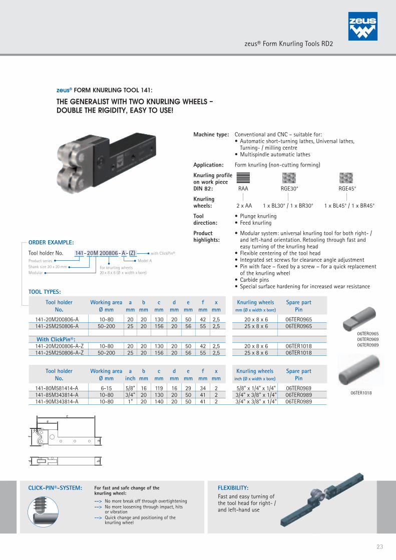
Modular system: universal knurling tool for both right- / and left-hand orientation. Retooling through fast and easy turning of the knurling head
EASY TOOL HANDLING:
Easy appliance and tool handling Minimal work piece preparation Integrated set screws for easy
adjustment of the clearance angle Pin with face – fixed by a screw – for a
quick replacement of the knurling wheel Click-pin® versions for still faster and safer
change of knurling wheels
HIGH WEAR RESISTANCE:
Special surface hardening forincreased tool life
Carbide pins for higher speedrates, faster production,prolonged life
APPLICATION EXAMPLE:
Threaded bushing M5
APPLICATION:Material: C35PbKnurling Profile/Pitch(DIN 82): RGE30°/P. 0,8Machine: Tornos SAS 16DC No. of pcs. produced/ knurling wheel: 120.000
APPLICATION PARAMETERS zeus® RD2:Knurling tool: 141-16M150604Knurling wheel: BL30° 15x6x4, P. 0,8 BR30° 15x6x4, P. 0,8Cycle time: 0,8 sec/pieceSpeed rate: 68 m/minFeed rate: 0,2 mm/revTool life knurling wheel: 1.600 min/knurling wheelPerformance: 19,2 m²/knurling wheel
21
zeus® FORM KNURLING TOOLS RD2-MODEL 141/142

Machine type: Conventional and CNC – suitable for: • Swiss type autolathes
Application: Form knurling (non-cutting forming)
Knurling profileon work piece DIN 82: RAA RGE30° RGE45°
Knurlingwheels: 2 x AA 1 x BL30° / 1 x BR30° 1 x BL45° / 1 x BR45°
Tool • Plunge knurling direction: • Feed knurling
Product • Modular shank construction for conversion to alternative highlights: shank sizes • Modular system: universal knurling tool for both right- / and left-hand orientation. Retooling through fast and easy turning of the knurling head • Flexible centering of the tool head • Integrated set screws for clearance angle adjustment • Pin with face – fixed by a screw – for a quick replacement of the knurling wheel • Carbide pins • Special surface hardening for increased wear resistance
zeus® FORM KNURLING TOOL 141:
THE GENERALIST WITH TWO KNURLING WHEELS – TWICE THE RIGIDITY, EASY TO USE!
FLEXIBILITY:Fast and easy turning ofthe tool head for right- /and left-hand use
TOOL TYPES:
ORDER EXAMPLE:
Product seriesShank size 8 x 8 mmModular
For knurling wheels 10 x 4 x 4 (Ø x width x bore)
Model A
Tool holder No. 141-08M 100404- A
Tool holder Working area a b c d e f x Knurling wheels Spare part No. Ø mm mm mm mm mm mm mm mm mm (Ø x width x bore) Pin
141-08M100404-A 3-12 8 8 105,5 12 25,5 21 1 10 x 4 x 4 06TER0960 141-10M100404-A 3-12 10 10 105,5 12 25,5 21 1 10 x 4 x 4 06TER0960 141-12M100404-A 3-12 12 12 105,5 12 25,5 23 1 10 x 4 x 4 06TER0960 141-16M100404-A 3-12 16 16 105,5 12 25,5 27 1 10 x 4 x 4 06TER0960 141-16M150604-A 5-40 16 16 129 16 39 33 1,5 15 x 6 x 4 06TER0964
Shank size Part-No.10 x 10 21BHR083312 x 12 21BHR083416 x 16 21BHR0835
SHANK ADAPTORS:
Modular shank construction for conversion to alternative shank sizes
06TER096006TER0964
cx e
f
a
d2(
3)
b
22
zeus® Form Knurling Tools RD2
CLICK-PIN®-SYSTEM: For fast and safe change of the knurling wheel:
--> No more break off through overtightening--> No more loosening through impact, hits
or vibration--> Quick change and positioning of the
knurling wheel
Machine type: Conventional and CNC – suitable for: • Automatic short-turning lathes, Universal lathes, Turning- / milling centre • Multispindle automatic lathes
Application: Form knurling (non-cutting forming)
Knurling profileon work piece DIN 82: RAA RGE30° RGE45°
Knurlingwheels: 2 x AA 1 x BL30° / 1 x BR30° 1 x BL45° / 1 x BR45°
Tool • Plunge knurling direction: • Feed knurling
Product • Modular system: universal knurling tool for both right- / highlights: and left-hand orientation. Retooling through fast and easy turning of the knurling head • Flexible centering of the tool head • Integrated set screws for clearance angle adjustment • Pin with face – fixed by a screw – for a quick replacement of the knurling wheel • Carbide pins • Special surface hardening for increased wear resistance
zeus® FORM KNURLING TOOL 141:
THE GENERALIST WITH TWO KNURLING WHEELS – DOUBLE THE RIGIDITY, EASY TO USE!
FLEXIBILITY:Fast and easy turning ofthe tool head for right- /and left-hand use
f
e c
abd
x
with ClickPin®
TOOL TYPES:
ORDER EXAMPLE:
Product seriesShank size 20 x 20 mmModular
For knurling wheels 20 x 8 x 6 (Ø x width x bore)
Model A
Tool holder No. 141-20M 200806- A- (Z)
Tool holder Working area a b c d e f x Knurling wheels Spare part No. Ø mm inch mm mm mm mm mm mm inch (Ø x width x bore) Pin
141-80M581414-A 6-15 5/8" 16 119 16 29 34 2 5/8" x 1/4" x 1/4" 06TER0969 141-85M343814-A 10-80 3/4" 20 130 20 50 41 2 3/4" x 3/8" x 1/4" 06TER0989 141-90M343814-A 10-80 1" 20 140 20 50 41 2 3/4" x 3/8" x 1/4" 06TER0989
06TER096506TER096906TER0989
06TER1018
Tool holder Working area a b c d e f x Knurling wheels Spare part No. Ø mm mm mm mm mm mm mm mm mm (Ø x width x bore) Pin
141-20M200806-A 10-80 20 20 130 20 50 42 2,5 20 x 8 x 6 06TER0965 141-25M250806-A 50-200 25 20 156 20 56 55 2,5 25 x 8 x 6 06TER0965 With ClickPin®: 141-20M200806-A-Z 10-80 20 20 130 20 50 42 2,5 20 x 8 x 6 06TER1018 141-25M250806-A-Z 50-200 25 20 156 20 56 55 2,5 25 x 8 x 6 06TER1018
23
zeus® Form Knurling Tools RD2

Machine type: Conventional and CNC – suitable for: • Automatic short-turning lathes, Universal lathes, Turning- / milling centre • Multispindle automatic lathes
Application: Form knurling (non-cutting forming)
Knurling profileon work piece DIN 82: RAA RGE30° RGE45°
Knurlingwheels: 2 x AA 1 x BL30° / 1 x BR30° 1 x BL45° / 1 x BR45°
Tool • Plunge knurling direction: • Feed knurling
Product • Knurling to a shoulder – knurling wheel fixed by a shoulder highlights: pin. Fitting of the knurling wheels on the pin adjustable • Modular system: universal knurling tool for right- / and left-hand orientation. Retooling through fast and easy turning of the knurling head • Flexible centering of the tool head • Integrated set screws for clearance angle adjustment • Carbide pins • Special surface hardening for increased wear resistance
zeus® FORM KNURLING TOOL 142:
THE GENERALIST WITH DOUBLE POWER UP TO A SHOULDER !
TOOL TYPES:
Tool holder Working area a b c d e f Knurling wheels Spare part Spare part No. Ø mm mm mm mm mm mm mm mm (Ø x width x bore) Shoulder pin Run disc
142-16M150611-A 8-15 16 16 119 19 39 33 15 x 6 x 6/11 06TER0380 21BHR0375 142-20M200813-A 10-80 20 20 130 24 50 42 20 x 8 x 6/13 06TER0383 21BHR0380 142-25M200813-A 10-80 25 20 130 24 50 42 20 x 8 x 6/13 06TER0383 21BHR0380
Tool holder Working area a b c d e f Knurling wheels Spare part Spare part No. Ø mm inch mm mm mm mm mm mm (Ø x width x bore) Shoulder pin Run disc
142-80M150611-A 8-15 5/8" 16 119 19 39 33 15 x 6 x 6/11 06TER0380 21BHR0375 142-85M200813-A 10-80 3/4" 20 130 24 50 42 20 x 8 x 6/13 06TER0383 21BHR0380 142-90M200813-A 10-80 1" 20 130 24 50 42 20 x 8 x 6/13 06TER0383 21BHR0380
ORDER EXAMPLE:
Product seriesShank size 16 x 16 mmModular
For knurling wheels 15 x 6 x 6 /11 (Ø x width x bore)
Model A
Tool holder No. 142-16 M 150611 - A
KNURLING TO A SHOULDER:Suitable for knurling up toa shoulder
FLEXIBILITY:Fast and easy turningof the tool head for right- /and left-hand use
06TER038006TER0383
ce
f
abd
21BHR037521BHR0380
24
zeus® Form Knurling Tools RD2
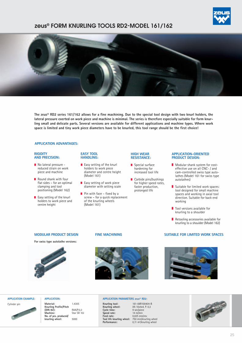
The zeus® RD2 series 161/162 allows for a fine machining. Due to the special tool design with two knurl holders, thelateral pressure exerted on work piece and machine is minimal. The series is therefore especially suitable for form knur-ling small and delicate parts. Several versions are available for different applications and machine types. Where workspace is limited and tiny work piece diameters have to be knurled, this tool range should be the first choice!
MODULAR PRODUCT DESIGN SUITABLE FOR LIMITED WORK SPACES
For swiss type autolathe versions:
FINE MACHINING
APPLICATION EXAMPLE:
Cylinder pin
APPLICATION:
Material: 1.4305Knurling Profile/Pitch(DIN 82): RAA/P.0,3Machine: Star SR 10JNo. of pcs. produced/ knurling wheel: 5000
APPLICATION PARAMETERS zeus® RD2:
Knurling tool: 161-08R100404-B Knurling wheel: AA 10x4x4, P. 0,3Cycle time: 9 sec/pieceSpeed rate: 14 m/minFeed rate: 0,025 mm/revTool life knurling wheel: 750 min/knurling wheelPerformance: 0,11 m²/knurling wheel
APPLICATION ADVANTAGES:
APPLICATION-ORIENTEDPRODUCT DESIGN:
Modular shank system for cost-effective use on all CNC- / and cam-controlled swiss type auto-lathes (Model 161 for swiss type autolathes)
Suitable for limited work spaces: tool designed for small machine spaces and working in axial tool direction. Suitable for back end working
Tool versions available for knurling to a shoulder
Retooling accessories available for knurling to a shoulder (Model 162)
RIGIDITYAND PRECISION:
No lateral pressure - reduced strain on work piece and machine
Round shank with four flat sides – for an optimal clamping and tool positioning (Model 162)
Easy setting of the knurl holders to work piece and centre height
EASY TOOLHANDLING:
Easy setting of the knurl holders to work piece diameter and centre height (Model 161)
Easy setting of work piece diameter with setting scale
Pin with face – fixed by a screw – for a quick replacement of the knurling wheels (Model 161)
HIGH WEARRESISTANCE:
Special surface hardening for increased tool life
Carbide pins/bushings for higher speed rates, faster production, prolonged life
25
zeus® FORM KNURLING TOOLS RD2-MODEL 161/162

Machine type: Conventional and CNC – suitable for: • Swiss type autolathes
Application: Form knurling (non-cutting forming)
Knurling profileon work piece DIN 82: RAA RGE30° RGE45°
Knurlingwheels: 2 x AA 1 x BL30° / 1 x BR30° 1 x BL45° / 1 x BR45°
Tool • Plunge knurling direction: • Feed knurling
Product • Modular shank construction for conversion to alternativehighlights: shank sizes • Pin with face – fixed by a screw – for a quick replacement of the knurling wheel • Easy adjustment of the knurl holder to work piece diameter and centre height • Carbide pins • Special surface hardening for increased wear resistance
zeus® FORM KNURLING TOOL 161:
THE GENERALIST – DOUBLE FORCE FOR MINIMAL PRESSUREON SMALL WORK PIECES!
WITH SPINDLE + SETTING SCALE:
Easy and precise setting
NO LATERAL PRESSURE:
Reduced strain on work piece and machine
TOOL TYPES:
Tool holder Working area a b c d e f g x Knurling wheels Spare part No. Ø mm mm mm mm mm mm mm mm mm mm (Ø x width x bore) Pin
161-08L100404-B 1-10 8 8 105,5 18 25,5 30 30 1 10 x 4 x 4 06TER0960 161-08R100404-B 1-10 8 8 105,5 18 25,5 30 30 1 10 x 4 x 4 06TER0960 161-10L100404-B 1-10 10 10 105,5 18 25,5 30 30 1 10 x 4 x 4 06TER0960 161-10R100404-B 1-10 10 10 105,5 18 25,5 30 30 1 10 x 4 x 4 06TER0960 161-12L100404-B 1-10 12 12 105,5 18 25,5 30 30 1 10 x 4 x 4 06TER0960 161-12R100404-B 1-10 12 12 105,5 18 25,5 30 30 1 10 x 4 x 4 06TER0960 161-16L100404-B 1-10 16 16 105,5 18 25,5 30 30 1 10 x 4 x 4 06TER0960 161-16R100404-B 1-10 16 16 105,5 18 25,5 30 30 1 10 x 4 x 4 06TER0960
ORDER EXAMPLE:
Product seriesShank size 8 x 8 mmLeft-hand use
For knurling wheels 10 x 4 x 4 (Ø x width x bore)
Model B
Tool holder No. 161-08 L 100404- B
06TER0960
cc
e
gx
d 2
b b
a a
g
d2
x
26
zeus® Form Knurling Tools RD2

Machine type: Conventional and CNC – suitable for: • Automatic short-turning lathes, Universal lathes, Turning- / milling centre • Multispindle automatic lathes
Application: Form knurling (non-cutting forming)
Knurling profileon work piece DIN 82: RAA RGE30° RGE45°
Knurlingwheels: 2 x AA 1 x BL30° / 1 x BR30° 1 x BL45° / 1 x BR45°
Tool • Plunge knurling direction: • Feed knurling
Product • Pin with face – fixed by a screw – for a quick replacementhighlights: of the knurling wheel • Easy adjustment of the knurl holder to work piece diameter and centre height • Carbide pins • Special surface hardening for increased wear resistance
zeus® FORM KNURLING TOOL 161:
THE UNIVERSAL – DOUBLE OPERATION ON WHEELSFOR MAXIMUM RIGIDITY WITH MINIMAL PRESSURE!
TOOL TYPES:
ORDER EXAMPLE:
Product seriesShank size 16 x 16 mmLeft-hand use
For knurling wheels 20 x 6 x 6 (Ø x width x bore)
Tool holder No. 161-16 L 200606
Tool holder Working area a b c d e f g x Knurling wheels Spare part No. Ø mm mm mm mm mm mm mm mm mm mm (Ø x width x bore) Pin
161-16L200606 5-25 16 16 134 48 37 96 104 2 20 x 6 x 6 06TER0965 161-16R200606 5-25 16 16 134 48 37 96 104 2 20 x 6 x 6 06TER0965 161-16L250606 25-50 16 16 136,5 48 39,5 101 106,5 4,5 25 x 6 x 6 06TER0965 161-16R250606 25-50 16 16 136,5 48 39,5 101 106,5 4,5 25 x 6 x 6 06TER0965 161-20L200606 5-25 20 20 134 52 37 96 104 2 20 x 6 x 6 06TER0965 161-20R200606 5-25 20 20 134 52 37 96 104 2 20 x 6 x 6 06TER0965 161-20L250606 25-50 20 20 136,5 52 39,5 101 106,5 4,5 25 x 6 x 6 06TER0965 161-20R250606 25-50 20 20 136,5 52 39,5 101 106,5 4,5 25 x 6 x 6 06TER0965 161-25L200606 5-25 25 20 134 52 37 96 104 2 20 x 6 x 6 06TER0965 161-25R200606 5-25 25 20 134 52 37 96 104 2 20 x 6 x 6 06TER0965 161-25L250606 25-50 25 20 136,5 52 39,5 101 106,5 4,5 25 x 6 x 6 06TER0965 161-25R250606 25-50 25 20 136,5 52 39,5 101 106,5 4,5 25 x 6 x 6 06TER0965
Alternative versions available on demand: Working area > 50 mm, feed knurling with profile length > 100 mm, knurling to a shoulder
06TER0965
NO LATERAL PRESURE:
Reduced wear on work pieceand machine
b e d
c
g f ab
e
d
x
c
a
fg
x
27
zeus® Form Knurling Tools RD2
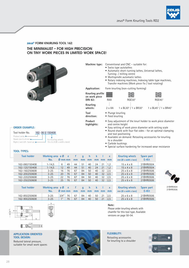
zeus® FORM KNURLING TOOL 162:
THE MINIMALIST – FOR HIGH PRECISIONON TINY WORK PIECES IN LIMITED WORK SPACE!
Machine type: Conventional and CNC – suitable for: • Swiss type autolathes • Automatic short-turning lathes, Universal lathes, Turning- / milling centre • Multispindle automatic lathes • Rotary indexing machines, Indexing table type machines, Transfer machines (Work piece fix / tool rotating)
Application: Form knurling (non-cutting forming)
Knurling profileon work piece DIN 82: RAA RGE30° RGE45°
Knurlingwheels: 2 x AA 1 x BL30° / 1 x BR30° 1 x BL45° / 1 x BR45°
Tool • Plunge knurling direction: • Feed knurling
Product • Easy adjustment of the knurl holder to work piece diameter highlights: and centre height • Easy setting of work piece diameter with setting scale • Round shank with four flat sides - for an optimal clamping and tool positioning • Available on demand: Retooling accessories for knurling to a shoulder • Carbide bushings • Special surface hardening for increased wear resistance
TOOL TYPES:
ORDER EXAMPLE:
Product seriesShank size 6 x 6 mmRight-/ and left- hand use
For knurling wheels 15 x 4 x 8 (Ø x width x bore)
Tool holder No. 162-06 U 150408
Tool holder Working area a Ø e f g h k l x Knurling wheels Spare part No. Ø mm mm mm mm mm mm mm mm mm (Ø x width x bore) E-Kit
162-06U150408 1-14,5 6 49 44 51 40 24 21 1,2 15 x 4 x 8 21BHR0504 162-12U150408 1-14,5 12 49 44 51 40 24 21 1,2 15 x 4 x 8 21BHR0504 162-16U250608 3-25 16 76 67 84 50 40 32 2,5 25 x 6 x 8 21BHR0506 162-20U250608 3-25 20 76 67 84 50 40 32 2,5 25 x 6 x 8 21BHR0506 162-22U250608 3-25 22 76 67 84 50 40 32 2,5 25 x 6 x 8 21BHR0506 162-25U250608 3-25 25 76 67 84 50 40 32 2,5 25 x 6 x 8 21BHR0506
Tool holder Working area a Ø e f g h k l x Knurling wheels Spare part No. Ø mm mm mm mm mm mm mm mm mm (Ø x width x bore) E-Kit
162-85U250608 3-25 3/4" 76 67 84 40 50 21 2,5 25 x 6 x 8 21BHR0506 162-90U250608 3-25 1" 76 67 84 40 50 21 2,5 25 x 6 x 8 21BHR0506
APPLICATION ORIENTEDTOOL DESIGN:Reduced lateral pressure,suitable for small work spaces
FLEXIBILITY:Retooling accessoriesfor knurling to a shoulder
21BHR050421BHR0506
Note: Please order knurling wheels with chamfer for this tool type. Available versions on page 50-54.
g f
e h
øa
k
lx
28
zeus® Form Knurling Tools RD2

zeus® FORM KNURLING TOOL 162:
THE MINIMALIST – FOR KNURLINGS TO A SHOULDERIN LIMITED WORK SPACES!
Machine type: Conventional and CNC – suitable for: • Swiss type autolathes • Automatic short-turning lathes, Universal lathes, Turning- / milling centre • Multispindle automatic lathes • Rotary indexing machines, Indexing table type machines, Transfer machines (Work piece fix / tool rotating)Application: Form knurling (non-cutting forming)Knurling profileon work piece DIN 82: RAA RGE30° RGE45°Knurlingwheels: 2 x AA 1 x BL30° / 1 x BR30° 1 x BL45° / 1 x BR45°Tool • Plunge knurling direction: • Feed knurlingProduct • Knurling to a shoulder – knurling wheel fixed by a shoulderhighlights: pin. Fitting of the knurling wheels on the pin adjustable • Easy adjustment of the knurl holder to work piece diameter and centre height • Easy setting of work piece diameter with setting scale • Round shank with four flat sides – for an optimal clamping and tool positioning • Special surface hardening for increased wear resistance
APPLICATION-ORIENTEDTOOL DESIGN:Reduced lateral pressure,suitable for small work spaces
KNURLING TO A SHOULDER:Suitable for knurling to a shoulder
g f
e h
øa
k
l
TOOL TYPES:
ORDER EXAMPLE:
Product seriesShank size 6 x 6 mmRight-/ and left- hand use
For knurling wheels 15 x 6 /11 (Ø x width x bore)
Tool holder No. 162-06 U 150611
Tool holder Working area a Ø e f g h k l Knurling wheels Spare part Spare part No. Ø mm mm mm mm mm mm mm mm mm (Ø x width x bore) Shoulder pin Run disc
162-06U150611 1-14 6 49 44 51 40 24 22 15 x 6 x 6/11 06TER0380 21BHR0375 162-12U150611 1-14 12 49 44 51 40 24 22 15 x 6 x 6/11 06TER0380 21BHR0375 162-16U200813 4-27,5 16 76 67 80 50 40 32 20 x 8 x 6/13 06TER0383 21BHR0380 162-20U200813 4-27,5 20 76 67 80 50 40 32 20 x 8 x 6/13 06TER0383 21BHR0380 162-22U200813 4-27,5 22 76 67 80 50 40 32 20 x 8 x 6/13 06TER0383 21BHR0380 162-25U200813 4-27,5 25 76 67 80 50 40 32 20 x 8 x 6/13 06TER0383 21BHR0380
Tool holder Working area a Ø e f g h k l Knurling wheels Spare part Spare part No. Ø mm inch mm Ømm mm mm mm mm mm (Ø x width x bore) Shoulder pin Run disc
162-85U200813 4-27,5 3/4" 76 67 80 50 40 32 20 x 8 x 6/13 06TER0383 21BHR0380 162-90U200813 4-27,5 1" 76 67 80 50 40 32 20 x 8 x 6/13 06TER0383 21BHR0380
06TER038006TER0383
21BHR037521BHR0380
29
zeus® Form Knurling Tools RD2
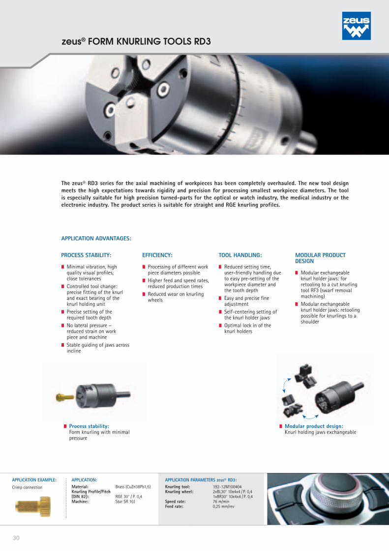
The zeus® RD3 series for the axial machining of workpieces has been completely overhauled. The new tool design meets the high expectations towards rigidity and precision for processing smallest workpiece diameters. The tool is especially suitable for high precision turned-parts for the optical or watch industry, the medical industry or the electronic industry. The product series is suitable for straight and RGE knurling profiles.
APPLICATION ADVANTAGES:
PROCESS STABILITY:
Minimal vibration, high quality visual profiles, close tolerances
Controlled tool change: precise fitting of the knurl and exact bearing of the knurl holding unit
Precise setting of the required tooth depth
No lateral pressure – reduced strain on work piece and machine
Stable guiding of jaws across incline
MODULAR PRODUCT DESIGN
Modular exchangeable knurl holder jaws: for retooling to a cut knurling tool RF3 (swarf removal machining)
Modular exchangeable knurl holder jaws: retooling possible for knurlings to a shoulder
TOOL HANDLING:
Reduced setting time, user-friendly handling due to easy pre-setting of the workpiece diameter and the tooth depth
Easy and precise fine adjustment
Self-centering setting of the knurl holder jaws
Optimal lock in of the knurl holders
EFFICIENCY:
Processing of different work piece diameters possible
Higher feed and speed rates, reduced production times
Reduced wear on knurling wheels
Process stability: Form knurling with minimal
pressure
Modular product design: Knurl holding jaws exchangeable
APPLICATION EXAMPLE:
Crimp connection
APPLICATION:Material: Brass (CuZn38Pb1,5)Knurling Profile/Pitch(DIN 82): RGE 30° / P. 0,4Machine: Star SR 10J
APPLICATION PARAMETERS zeus® RD3:Knurling tool: 192-12M100404 Knurling wheel: 2xBL30° 10x4x4 / P. 0,4 1xBR30° 10x4x4 / P. 0,4Speed rate: 76 m/minFeed rate: 0,25 mm/rev
30
zeus® FORM KNURLING TOOLS RD3

zeus® FORM KNURLING TOOL 192:
THE ALL-ROUNDER – A SAFE BET ON ALL MACHINE TYPESFOR MAXIMUM RIGIDITY WITH MINIMAL PRESSURE!
Machine type: Conventional and CNC – suitable for: • Lathe / autolathes • Swiss type autolathes • Automatic short-turning lathes, Universal lathes, Turning- / milling centre • Multispindle automatic lathes • Rotary indexing machines, Indexing table type machines, Transfer machines (Work piece fixed / tool rotating)Application: Form knurling (non-cutting forming)Knurling profileon work piece DIN 82: RAA RGE30° RGE45°Knurlingwheels: 3 x AA 1xBL30° / 2xBR30° 1xBL15° / 2xBR15° or 2xBL30° / 1xBR30° or 2xBL15° / 1xBR15°Tool direction: • Feed knurlingProduct • No lateral pressure – reduced strain on work piece highlights: and machine • Easy and precise fine adjustment • Modular exchangeable knurl holder jaws: for retooling to a cut knurling tool RF3 (swarf removal machining) or knurling to a shoulder • Carbide bushings • Special surface hardening for increased wear resistance
TOOL TYPES:
Tool holder Working area a d e h j k l m x Knurling wheels No. Ø mm Ø mm Ø mm mm mm Ø mm Ø mm mm mm mm mm (Ø x width x bore) 192-12M100404-B 2,5 - 14 12 52 81 45 9 52 2 56 1,5 10 x 4 x 4 192-12M150608-B 2,5 - 14 12 52 83 45 9 52 4 58 1,5 15 x 6 x 6/8
d = max. work piece Ø
ORDER EXAMPLE:
Product seriesShank size Ø 12Modular
For knurling wheels 10 x 4 x 4 (Ø x width x bore)
Model B
Tool holder No. 192-12 M 100404-B
m = max. work piece length (with Øj)
Further tool dimensions available on demand.
MODULARTEILE:
Form knurling
Cut knurling
Knurling to a shoulder
Modular jawsMODULAR PARTS:Optionally available for cutknurling / knurling to a shouler
hx
e
d j a k
31
zeus® Form Knurling Tools RD3
High precision for connectors, bushings, fittings, housings, etc., as required in the electronic, automotive industry or fluid technology
Superb visual knurling profiles for the watch-making or surgical industry
PROCESS STABILITY:
Minimal vibration, high quality visual profiles, close tolerances
Reproducible processes through scaling and positioning aids
All setting parameters can be preset and docu-mented
Controlled tool change: precise fitting of the knurl and exact location of the knurl holding unit
EFFICIENCY:
Higher feed and speed rates, reduced production times
Reduced wear on knurling wheels
Modular shank system for cost-effective use on all CNC- / and cam- controlled swiss type autolathes
Modular cut knurling tool head for right-/left-hand use and different work piece diameters
TOOL HANDLING:
Reduced setting times, user-friendly fine adjustment of the clearance angle and the knurling tool head
Easy change of knurling wheels and precise positioning of the knurl holding unit
APPLICATION ADVANTAGES:
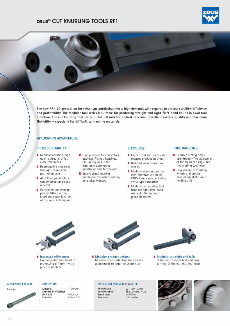
The new RF1-LD generation for swiss type autolathes meets high demands with regards to process stability, efficiency and profitability. The modular tool series is suitable for producing straight and right-/left-hand knurls in axial tool direction. The cut knurling tool series RF1-LD stands for highest precision, excellent surface quality and maximum flexibility – especially for difficult to machine materials.
Increased efficiency: Exchangeable tool head for
processing different work piece diameters
Modular product design: Modular shank adaptors for an easy
adjustment to required shank size
Modular use right and left: Retooling through fast and easy
turning of the cut knurling head
APPLICATION EXAMPLE:
Knurl pin
APPLICATION:
Material: 11SMn30Knurling Profile/Pitch(DIN 82): RAA/P.0,8Machine: Citizen C 3L
APPLICATION PARAMETERS zeus® RF1
Knurling tool: 231-16M150408 Knurling wheel: BR30°15x4x8, P. 0,8Speed rate: 60 m/minFeed rate: 0,13 mm/rev
32
zeus® CUT KNURLING TOOLS RF1
b
a
21BHR0792
MODULAR PARTS: CUT KNURLING HEADS:
Working area Cut knurling head Part-No.1,5 - 12 mm RFK 10x3x6 21BHR07933 - 50 mm RFK 15x4x8 21BHR0794
Shank size Part-No.10 x 10 21BHR083312 x 12 21BHR083416 x 16 21BHR0835
Modular shank construction for conversion to alternative shank sizes Optional: For conversion to alternative working area
SHANK ADAPTORS:
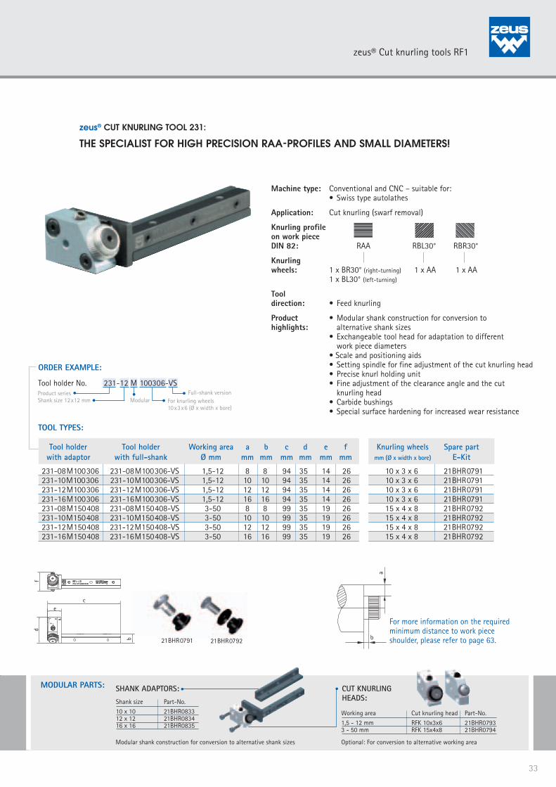
zeus® CUT KNURLING TOOL 231:
THE SPECIALIST FOR HIGH PRECISION RAA-PROFILES AND SMALL DIAMETERS!
ORDER EXAMPLE:
Tool holder No. 231-12 M 100306-VSProduct seriesShank size 12x12 mm Modular For knurling wheels
10x3x6 (Ø x width x bore)
Full-shank version
21BHR0791
Tool holder Tool holder Working area a b c d e f Knurling wheels Spare part with adaptor with full-shank Ø mm mm mm mm mm mm mm mm (Ø x width x bore) E-Kit
231-08M100306 231-08M100306-VS 1,5-12 8 8 94 35 14 26 10 x 3 x 6 21BHR0791231-10M100306 231-10M100306-VS 1,5-12 10 10 94 35 14 26 10 x 3 x 6 21BHR0791231-12M100306 231-12M100306-VS 1,5-12 12 12 94 35 14 26 10 x 3 x 6 21BHR0791231-16M100306 231-16M100306-VS 1,5-12 16 16 94 35 14 26 10 x 3 x 6 21BHR0791231-08M150408 231-08M150408-VS 3-50 8 8 99 35 19 26 15 x 4 x 8 21BHR0792231-10M150408 231-10M150408-VS 3-50 10 10 99 35 19 26 15 x 4 x 8 21BHR0792231-12M150408 231-12M150408-VS 3-50 12 12 99 35 19 26 15 x 4 x 8 21BHR0792231-16M150408 231-16M150408-VS 3-50 16 16 99 35 19 26 15 x 4 x 8 21BHR0792
TOOL TYPES:
Machine type: Conventional and CNC – suitable for: • Swiss type autolathes
Application: Cut knurling (swarf removal)
Knurling profileon work piece DIN 82: RAA RBL30° RBR30°
Knurling wheels: 1 x BR30° (right-turning) 1 x AA 1 x AA 1 x BL30° (left-turning)
Tool direction: • Feed knurling
Product • Modular shank construction for conversion to highlights: alternative shank sizes • Exchangeable tool head for adaptation to different work piece diameters • Scale and positioning aids • Setting spindle for fine adjustment of the cut knurling head • Precise knurl holding unit • Fine adjustment of the clearance angle and the cut knurling head • Carbide bushings • Special surface hardening for increased wear resistance
fd
ce
b
For more information on the required minimum distance to work piece shoulder, please refer to page 63.
33
zeus® Cut knurling tools RF1

PROCESS STABILITY:
Process stability through protection from radial deflection and axial torque: for an optimal tool guiding of the work piece and mini-mal vibration of the tool. Superb precision and surface quality on the work piece. Easy and precise positioning of the cut knurling head
Lock-in position at 30° - for an optimal starting position
Precise fine adjustment of the tool head by means of scaling aid: for an easy presetting and reproducible processes
EFFICIENCY:
Higher feed and speed rates, reduced production times
Reduced wear on knurling wheels
Modular cut knurling tool head for right-/left-hand turning machines
Reduced setting time through easy presetting and reproducible setting parameters
TOOL HANDLING:
Integrated set screws for easy adjustment of the clearance angle
Fine adjustment of the cut knurling head with setting spindle for a perfectly milled profile and even knurl depth
Easy change of knurling wheels and precise position-ing of the knurl holding unit
Stability and precision due to a three-point bearing of the tool head on the shank construction
APPLICATION ADVANTAGES:
The alternative for knurling impressive RAA profiles. Setting and scaling aids for a fine adjustment of the cut knurling head offer special advantages concerning precision, knurl quality and user-friendliness. The simplified tool setting in combination with a more stable design allow for increased process rigidity. The optimal tool solution for visual knurling profiles with minimal pressure!
+ 120°turn
Controlled tool change: precise fitting of the knurl and exact location of the knurl holding unit
All setting parameters can be preset and documented
Modular use right and left: Retooling through fast and easy
turning of the cut knurling head
User-friendly tool handling: Scaling and positioning aids
Setting spindle
Scaling aids
APPLICATION EXAMPLE:
Housing
APPLICATION:
Material: 1.4305Knurling Profile/Pitch(DIN 82): RAA / TIg 1,0Machine: Boley BE 42No. of pcs. produced/ knurling wheel: 400
APPLICATION PARAMETERS zeus® RF1:
Knurling tool: 231-20M250608-A Knurling wheel: BR30° 25x6x8, P. 1,0Cycle time: 25 sec/pieceSpeed rate: 35 m/minFeed rate: 0,08 mm/revTool life knurling wheel: 166 min/knurling wheelPerformance: 0,72 m²/knurling wheel
RL
R L
34
zeus® CUT KNURLING TOOLS RF1
b
a
Model A
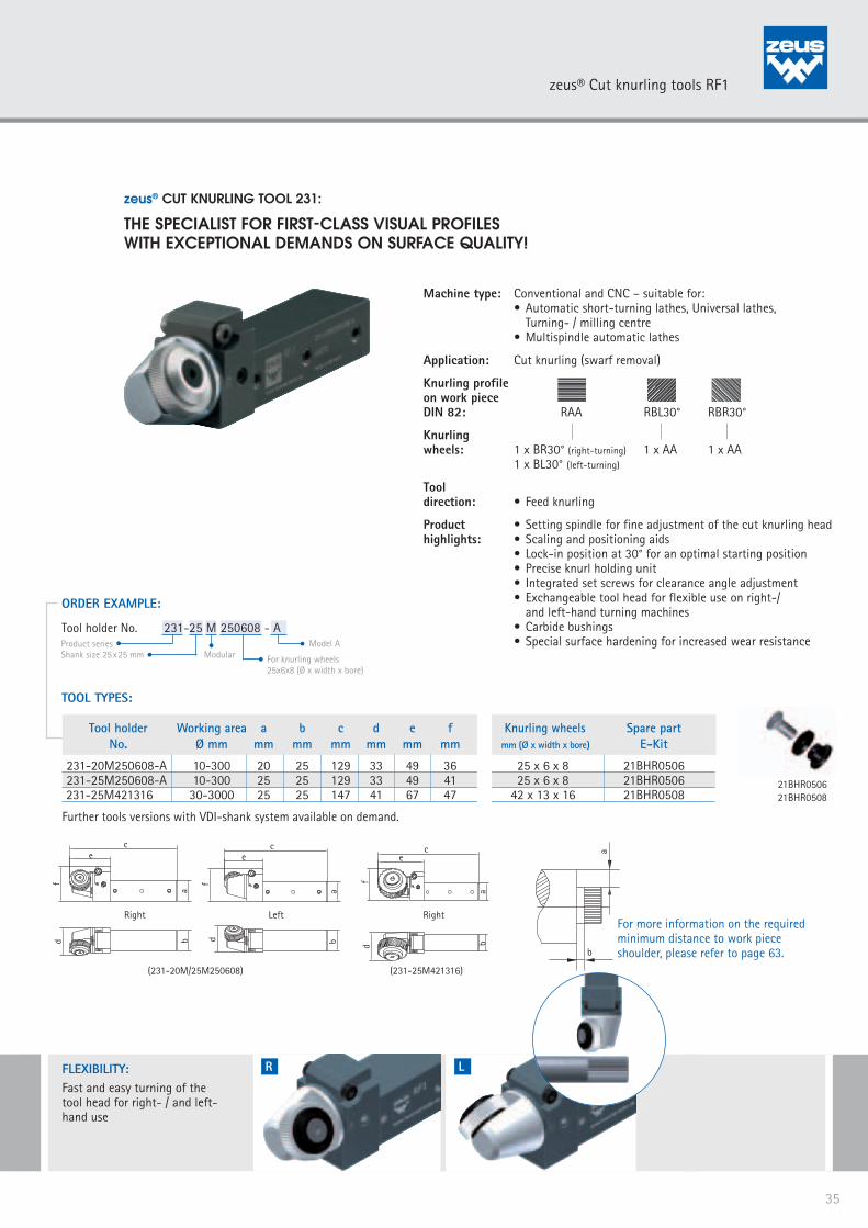
zeus® CUT KNURLING TOOL 231:
THE SPECIALIST FOR FIRST-CLASS VISUAL PROFILESWITH EXCEPTIONAL DEMANDS ON SURFACE QUALITY!
21BHR050621BHR0508
Machine type: Conventional and CNC – suitable for: • Automatic short-turning lathes, Universal lathes, Turning- / milling centre • Multispindle automatic lathes
Application: Cut knurling (swarf removal)
Knurling profileon work piece DIN 82: RAA RBL30° RBR30°
Knurling wheels: 1 x BR30° (right-turning) 1 x AA 1 x AA 1 x BL30° (left-turning)
Tool direction: • Feed knurling
Product • Setting spindle for fine adjustment of the cut knurling headhighlights: • Scaling and positioning aids • Lock-in position at 30° for an optimal starting position • Precise knurl holding unit • Integrated set screws for clearance angle adjustment • Exchangeable tool head for flexible use on right-/ and left-hand turning machines • Carbide bushings • Special surface hardening for increased wear resistance
ORDER EXAMPLE:
Tool holder No. 231-25 M 250608 - AProduct seriesShank size 25x25 mm Modular For knurling wheels
25x6x8 (Ø x width x bore)
Tool holder Working area a b c d e f Knurling wheels Spare part No. Ø mm mm mm mm mm mm mm mm (Ø x width x bore) E-Kit
231-20M250608-A 10-300 20 25 129 33 49 36 25 x 6 x 8 21BHR0506 231-25M250608-A 10-300 25 25 129 33 49 41 25 x 6 x 8 21BHR0506 231-25M421316 30-3000 25 25 147 41 67 47 42 x 13 x 16 21BHR0508
TOOL TYPES:
FLEXIBILITY:Fast and easy turning of the tool head for right- / and left-hand use
R L
bd
ce
f
a
(231-20M/25M250608)
Right
bd
ce
f
a
Left
bd
ce
f
a
(231-25M421316)
Right
Further tools versions with VDI-shank system available on demand.
For more information on the required minimum distance to work piece shoulder, please refer to page 63.
35
zeus® Cut knurling tools RF1

The new RF2-LD generation for swiss type autolathes meets high demands with regards to process stability, efficiency and profitability. Due to the modular system with four shank adaptors and two cut knurling heads, the tool series can be adjusted easily to different applications and machine types. The small but rigid tool design is ideal for limited work spaces, and excels also in long-term operations. The best alternative for producing excellent RGE profiles on small diameters.
Increased efficiency: Exchangeable tool head for
processing different work piece diameters
Modular product design: Modular shank adaptors for an easy
adjustment to required shank size
Modular use right and left: Retooling through fast and easy
turning of the cut knurling head
APPLICATION ADVANTAGES:
PROCESS STABILITY:
Minimal vibration, high quality visual profiles, close tolerances
Serration between tool holder and cut knurling head for increased stability and precision during processing
Fine adjustment of the knurl head through setting spindle (with scale) – ensuring a knurling profile parallel to the axis
Precise fine adjustment of the tool head by means of scaling aid: for an easy presetting and reproducible processes
TOOL HANDLING:
Reduced setting times through user-friendly fine adjustment of the clearance angle and the knurling tool head
User-friendly fine adjust-ment of the center height through vertical height ad-justment with the setting spindle
Easy setting of the work piece diameter with the setting scale and the synchronously adjusted setting spindle
EFFICIENCY:
Higher feed and speed rates, reduced production times
Reduced wear on knurling wheels
Modular shank system for cost-effective use on all CNC- / and cam-controlled swiss type autolathes
Modular cut knurling tool head for right-/lefthand use
All setting parameters can be preset and documented
Controlled tool change: precise fitting of the knurl and exact location of the knurl holding unit
Rigid tool construction allows an exact positioning of the cut knurling tool head – for an optimal tool guiding on the work piece
APPLICATION EXAMPLE:
Knurled screw
APPLICATION:Material: 9SMnPb28KKnurling Profile/Pitch(DIN 82): RGE30°/P. 1,0Machine: Boley BE42No. of pcs. produced/ knurling wheel: 2.000
APPLICATION PARAMETERS zeus® RF2:Knurling tool: 241-16M150408 Knurling wheel: AA 15x4x8, P. 1,0 AA 15x4x8, P. 1,0Cycle time: 10 sec/pieceSpeed rate: 55 m/minFeed rate: 0,1 mm/revTool life knurling wheel: 330 min/knurling wheelPerformance: 1,41 m²/knurling wheel
36
zeus® CUT KNURLING TOOLS RF2
b
a
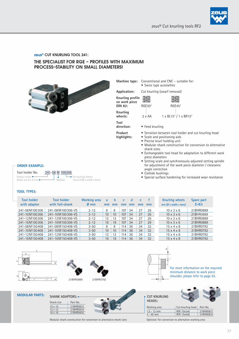
zeus® CUT KNURLING TOOL 241:
THE SPECIALIST FOR RGE – PROFILES WITH MAXIMUMPROCESS–STABILITY ON SMALL DIAMETERS!
Machine type: Conventional and CNC – suitable for: • Swiss type autolathes
Application: Cut knurling (swarf removal)
Knurling profileon work piece DIN 82: RGE30° RGE45°
Knurlingwheels: 2 x AA 1 x BL15° / 1 x BR15°
Tool direction: • Feed knurling
Product • Serration between tool holder and cut knurling head highlights: • Scale and positioning aids • Precise knurl holding unit • Modular shank construction for conversion to alternative shank sizes • Exchangeable tool head for adaptation to different work piece diameters • Setting scale and synchronously adjusted setting spindle for adjustment of the work piece diameter / clearance angle correction • Carbide bushings • Special surface hardening for increased wear resistance
21BHR079221BHR0889
ORDER EXAMPLE:
Tool holder No. 241-08 M 100306Product seriesShank size 8 x 8 mm Modular
For knurling wheels 10x3x6 (Ø x width x bore)
TOOL TYPES:
MODULARTEILE:MODULAR PARTS: CUT KNURLING HEADS:
Working area Cut knurling head Part-No.1,5 - 12 mm RFK 10x3x6 21BHR08313 - 50 mm RFK 15x4x8 21BHR0832
Shank size Part-No.10 x 10 21BHR083312 x 12 21BHR083416 x 16 21BHR0835
Modular shank construction for conversion to alternative shank sizes Optional: For conversion to alternative working area
SHANK ADAPTORS:
ce
f
ab
d
Tool holder Tool holder Working area a b c d e f Knurling wheels Spare part with adaptor with full-shank Ø mm mm mm mm mm mm mm mm (Ø x width x bore) E-Kit
241-08M100306 241-08M100306-VS 2-12 8 8 107 34 27 26 10 x 3 x 6 21BHR0889241-10M100306 241-10M100306-VS 2-12 10 10 107 34 27 26 10 x 3 x 6 21BHR0889241-12M100306 241-12M100306-VS 2-12 12 12 107 34 27 26 10 x 3 x 6 21BHR0889241-16M100306 241-16M100306-VS 2-12 16 16 107 34 27 29 10 x 3 x 6 21BHR0889241-08M150408 241-08M150408-VS 3-50 8 8 114 36 34 32 15 x 4 x 8 21BHR0792241-10M150408 241-10M150408-VS 3-50 10 10 114 36 34 32 15 x 4 x 8 21BHR0792241-12M150408 241-12M150408-VS 3-50 12 12 114 36 34 32 15 x 4 x 8 21BHR0792241-16M150408 241-16M150408-VS 3-50 16 16 114 36 34 32 15 x 4 x 8 21BHR0792
For more information on the required minimum distance to work piece shoulder, please refer to page 63.
37
zeus® Cut knurling tools RF2

APPLICATION ADVANTAGES:
Maximum rigidity, process stability and simplified handling: These are the advantages of the new RF2-A generation. The tool series is mainly suitable for producing RGE profiles. Serration between tool holder and cut knurling head provides extra rigidity and reduced wear on the knurling wheels. A special advantage offers the vertical height adjustment for a flexible use on different shank sizes. Setting aids for fine adjustment of the cut knurling head make the tool setting easy and offer increased process stability for exacting work pieces.
PROCESS STABILITY:
Serration between tool holder and cut knurling head – for increased rigidity and precision
Rigid tool construction allows an exact positioning of the cut knurling tool head – for an optimal tool guiding on the work piece and minimal vibration of the tool. Superb precision and surface quality on the work piece
Precise positioning of the tool head by means of scaling aid – for an easy presetting and repro-ducible processes
Controlled tool change: precise fitting of the knurl and exact location of the knurl holding unit
TOOL HANDLING:
Reduced setting time through easy presetting and reproducible setting parameters
User-friendly fine adjustment of the center height through vertical height adjustment with the setting spindle
Easy setting of the work piece diameter with the setting scale and the synchronously adjusted setting spindle
Fine adjustment of the knurl head through setting spindle (with scale) – ensuring a knurling profile parallel to the axis
Fine-adjustment through adjustable knurling tool head
EFFICIENCY:
Universal use – tool designed for machines with both 20 and 25 mm shanks
Through the vertical height adjustment the tool can be used flexibly for both shank sizes
Modular cut knurling tool head for right- / left-hand use
Higher feed and speed rates, reduced production times
Reduced wear on knurling wheels
UNIVERSAL USE:
Vertical height adjustment for center height 20 and 25 mm
MODULAR USE RIGHT AND LEFT:
Retooling through fast and easy turning of the cut knurling head
APPLICATION EXAMPLE:
Housing
APPLICATION:
Material: 9SMnPb28KKnurling Profile/Pitch(DIN 82): RGE30°, P. 1,0Machine: IndexNo. of pcs. produced/ knurling wheel: 1.000
APPLICATION PARAMETERS zeus® RF2:
Knurling tool: 241-20/25M250608-A.1 Knurling wheel: AA 25x6x8, P. 1,0Cycle time: 15 sec/pieceSpeed rate: 47 m/minFeed rate: 0,1 mm/revTool life knurling wheel: 250 min/knurling wheelPerformance: 1,4 m²/knurling wheel
38
zeus® CUT KNURLING TOOLS RF2
b
a
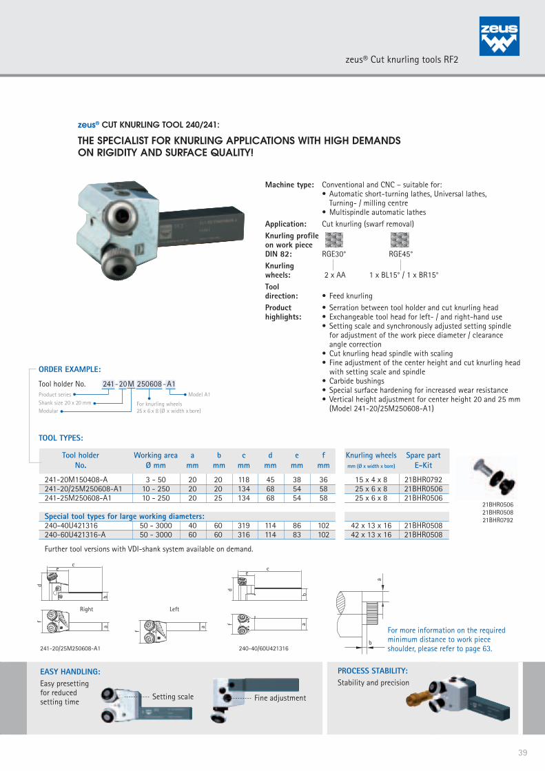
zeus® CUT KNURLING TOOL 240/241:
THE SPECIALIST FOR KNURLING APPLICATIONS WITH HIGH DEMANDSON RIGIDITY AND SURFACE QUALITY!
Machine type: Conventional and CNC – suitable for: • Automatic short-turning lathes, Universal lathes, Turning- / milling centre • Multispindle automatic lathesApplication: Cut knurling (swarf removal)Knurling profileon work piece DIN 82: RGE30° RGE45°Knurlingwheels: 2 x AA 1 x BL15° / 1 x BR15°Tool direction: • Feed knurlingProduct • Serration between tool holder and cut knurling head highlights: • Exchangeable tool head for left- / and right-hand use • Setting scale and synchronously adjusted setting spindle for adjustment of the work piece diameter / clearance angle correction • Cut knurling head spindle with scaling • Fine adjustment of the center height and cut knurling head with setting scale and spindle • Carbide bushings • Special surface hardening for increased wear resistance • Vertical height adjustment for center height 20 and 25 mm (Model 241-20/25M250608-A1)
PROCESS STABILITY:Stability and precision
EASY HANDLING:Easy presettingfor reducedsetting time
Setting scale Fine adjustment
Tool holder Working area a b c d e f Knurling wheels Spare part No. Ø mm mm mm mm mm mm mm mm (Ø x width x bore) E-Kit
241-20M150408-A 3 - 50 20 20 118 45 38 36 15 x 4 x 8 21BHR0792241-20/25M250608-A1 10 - 250 20 20 134 68 54 58 25 x 6 x 8 21BHR0506241-25M250608-A1 10 - 250 20 25 134 68 54 58 25 x 6 x 8 21BHR0506
Special tool types for large working diameters:240-40U421316 50 - 3000 40 60 319 114 86 102 42 x 13 x 16 21BHR0508 240-60U421316-A 50 - 3000 60 60 316 114 83 102 42 x 13 x 16 21BHR0508
Further tool versions with VDI-shank system available on demand.
TOOL TYPES:
ORDER EXAMPLE:
Product seriesShank size 20 x 20 mmModular
For knurling wheels 25 x 6 x 8 (Ø x width x bore)
Model A1
Tool holder No. 241-20 M 250608-A1
21BHR050621BHR050821BHR0792
af
ce
d
b
240-40/60U421316241-20/25M250608-A1
a
f
Left
a
f
ce
d
b
Right
For more information on the required minimum distance to work piece shoulder, please refer to page 63.
39
zeus® Cut knurling tools RF2

The zeus® RF3 series is designed for the fine machining of very small and thin-walled work pieces in axial tool direction. The product series is suitable for producing straight and RGE profiles with high demands on surface quality and dimensional accuracy. Due to the special design with three knurling wheels operating, the lateral pressure is reduced to a minimum. zeus® RF3: A specialist for knurling thin or pressure-sensitive parts, as for example spindles, tubes, or delicate bushings.
Modular product design:Knurl holder-jaws exchangeable
APPLICATION ADVANTAGES:
MODULAR PRODUCT DESIGN:
Modular exchangeable knurl holder-jaws: for retooling to a form knurling tool RD3 (Non-cutting forming)
Modular exchangeable knurl holder-jaws: retooling possible for knurling to a shoulder
TOOL HANDLING:
Reduced setting time, user-friendly handling due to easy pre-setting of the workpiece diameter and the tooth depth
Easy and precise fine adjustment
Self-centering setting of the knurl holder jaws
Optimal lock in of the knurl holders
EFFICIENCY:
Processing of different work piece diameters possible
Higher feed and speed rates, reduced production times
Reduced wear on knurling wheels
Modular tool design – easy adjustment to different application requirements
PROCESS STABILITY:
Minimal vibration, high quality visual profiles, close tolerances
No lateral pressure - reduced strain on work piece and machine
Controlled tool change: precise fitting of the knurl and exact bearing of the knurl holding unit
Precise setting of the required tooth depth and work piece diameter
No lateral pressure – reduced strain on work piece and machine
Stable guiding of jaws across incline
Process stability:Cut knurling with minimal pressure
APPLICATION EXAMPLE:
Turned-part, Endoscopy
APPLICATION:
Material: 1.4542Knurling Profile/Pitch(DIN 82): RGE30°/P. 0,8Machine: Maier Swiss type autolathe
APPLICATION PARAMETERS zeus® RF2:
Knurling tool: 291-12M100306-BKnurling wheel: 3xAA 10x3x6, P. 0,8 TENIFER treatedSpeed rate: 25 m/minFeed rate: 0,07 mm/rev
40
zeus® CUT KNURLING TOOLS RF3
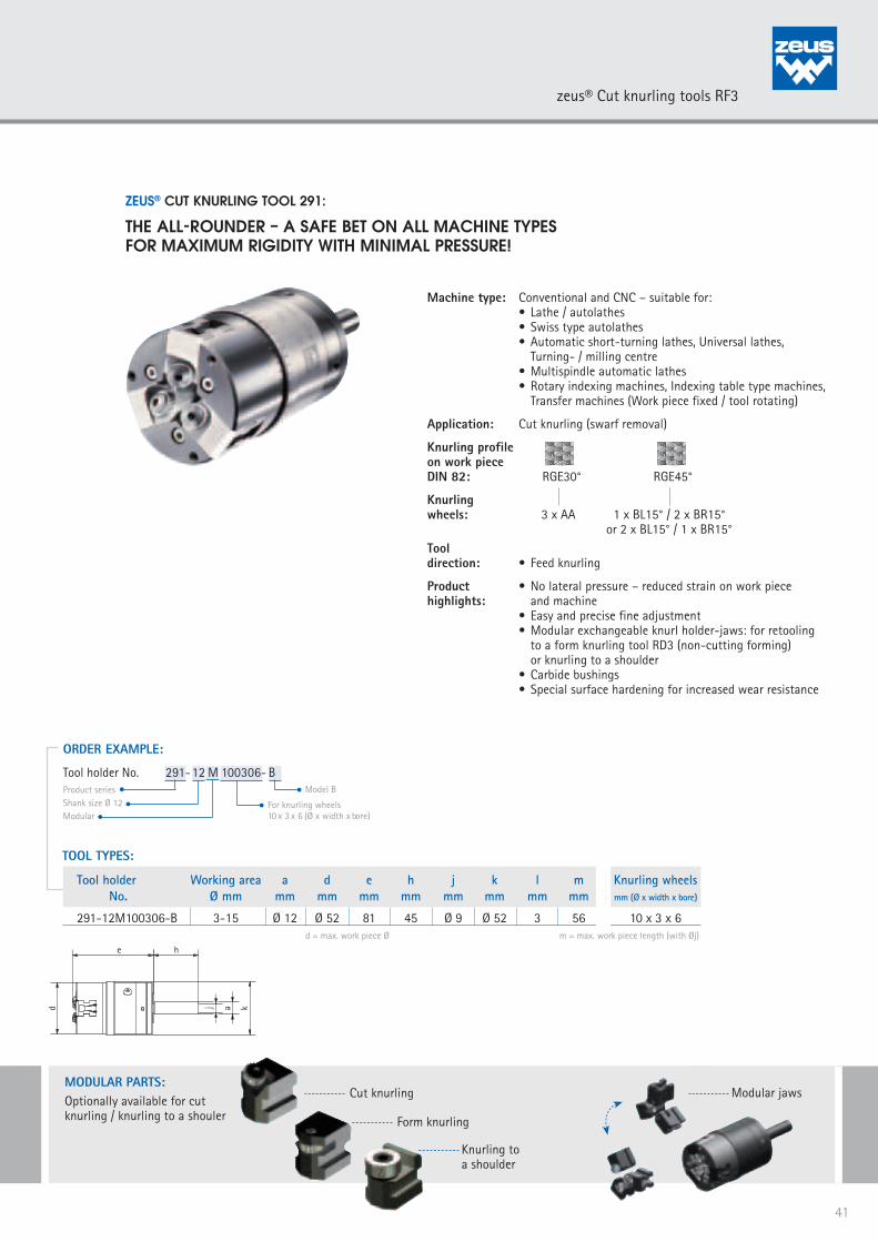
ZEUS® CUT KNURLING TOOL 291:
THE ALL-ROUNDER – A SAFE BET ON ALL MACHINE TYPESFOR MAXIMUM RIGIDITY WITH MINIMAL PRESSURE!
Machine type: Conventional and CNC – suitable for: • Lathe / autolathes • Swiss type autolathes • Automatic short-turning lathes, Universal lathes, Turning- / milling centre • Multispindle automatic lathes • Rotary indexing machines, Indexing table type machines, Transfer machines (Work piece fixed / tool rotating)
Application: Cut knurling (swarf removal)
Knurling profileon work piece DIN 82: RGE30° RGE45°
Knurlingwheels: 3 x AA 1 x BL15° / 2 x BR15° or 2 x BL15° / 1 x BR15°Tool direction: • Feed knurling
Product • No lateral pressure – reduced strain on work piece highlights: and machine • Easy and precise fine adjustment • Modular exchangeable knurl holder-jaws: for retooling to a form knurling tool RD3 (non-cutting forming) or knurling to a shoulder • Carbide bushings • Special surface hardening for increased wear resistance
TOOL TYPES:
ORDER EXAMPLE:
Product seriesShank size Ø 12Modular
For knurling wheels 10 x 3 x 6 (Ø x width x bore)
Tool holder No. 291-12 M 100306- B
Tool holder Working area a d e h j k l m Knurling wheels No. Ø mm mm mm mm mm mm mm mm mm mm (Ø x width x bore) 291-12M100306-B 3-15 Ø 12 Ø 52 81 45 Ø 9 Ø 52 3 56 10 x 3 x 6
d = max. work piece Ø
Model B
m = max. work piece length (with Øj)
MODULARTEILE:
Form knurling
Cut knurling
Knurling to a shoulder
Modular jawsMODULAR PARTS:Optionally available for cutknurling / knurling to a shouler
e h
j ad k
41
zeus® Cut knurling tools RF3

zeus® SPECIAL TOOLS 311/312:
THE SPECIALISTS FOR CONICAL AND FACE KNURLING
APPLICATION EXAMPLE:
Threaded insert
APPLICATION:
Material: 1.4305Knurling Profile/Pitch(DIN 82): RGE30°, P. 0,6Machine: INDEX ABCNo. of pcs. produced/ knurling wheel: 2.000
APPLICATION PARAMETERS zeus® special tools:
Knurling tool: Special toolKnurling wheel: GV30° 15x6x4, P. 0,6Cycle time: 2 sec/pieceSpeed rate: 33 m/minFeed rate: 0,2 mm/revTool life knurling wheel: 66 min/knurling wheelPerformance: 0,24 m²/knurling wheel
Note: Further tool versions available on demand. For more information, please order the zeus ® Special Tooling Catalogue.
zeus® SPECIAL TOOLS 311-45°
Machine type:Conventional and CNC – suitable for:• Lathe / autolathes• Automatic short-turning lathes, Universal
lathes, Turning-/milling centres• Multi spindle automatic lathes
Application: Conical knurlingFace knurling Form knurling (non-cutting forming)
Knurling profile on work piece DIN 82:
RAA RBL RBR RGE RGV
KAA KBR KBL KGV KGE (Knurling wheels)
Tool direction: • Plunge knurling
Product highlights:• Special surface hardening for
increased wear resistance
zeus® SPECIAL TOOLS 311-90°
Machine type:Conventional and CNC – suitable for:• Lathe / autolathes• Automatic short-turning lathes, Universal
lathes, Turning-/milling centres• Multi spindle automatic lathes
Application: Knurling within a bore - (up to a shoulder)Face knurling Form knurling (non-cutting forming)
Knurling profile on work piece DIN 82:
RAA RBL RBR RGE RGV RKE RKV
AA BR BL GV GE KV KE (Knurling wheels)
Tool direction: • Plunge knurling: Suitable for all
knurling profiles, patterns and markings• Feed knurling: Suitable for RAA, RBL, RBR
Product highlights:• Shoulder pin fixed by a screw• Special surface hardening for increased
wear resistance
zeus® SPECIAL TOOLS 312
Machine type:Conventional and CNC – suitable for:• Lathe / autolathes• Automatic short-turning lathes,
Universal lathes, Turning-/milling centres• Multi spindle automatic lathes
Application: Conical knurling Form knurling (non-cutting forming)
Knurling profile on work piece DIN 82:
RAA RBL RBR RGE RGV
KAA KBR KBL KGV KGE (Knurling wheels)
Tool direction: • Plunge knurling
Product highlights:• Integrated set screws for clearance angle
adjustment• Special surface hardening for increased
wear resistance
42
zeus® SPECIAL TOOLS

zeus® SPECIAL TOOLS 330/332/342:
THE PROFESSIONALS FOR KNURLING WITHIN A BORE!
zeus® SPECIAL TOOLS 330
Machine type:Conventional and CNC – suitable for:• Lathe / autolathes• Swiss type autolathes • Automatic short-turning lathes, Universal
lathes, Turning-/milling centres• Multi spindle automatic lathes
Application: Knurling within a bore Form knurling (non-cutting forming)
Knurling profile on work piece DIN 82:
RAA RBL RBR RGE RGV RKE RKV
AA BR BL GV GE KV KE (Knurling wheels)
Tool direction: • Plunge knurling: Suitable for all
knurling profiles, patterns and markings• Feed knurling: Suitable for RAA, RBL, RBR
Product highlights:• Suitable for small work spaces• Round shank with four clamping flats• Special surface hardening for increased wear resistance
zeus® SPECIAL TOOLS 332
Machine type:Conventional and CNC – suitable for:• Lathe / autolathes• Swiss type autolathes • Automatic short-turning lathes, Universal
lathes, Turning-/milling centres• Multi spindle automatic lathes
Application: Knurling within a bore - (up to a shoulder) Form knurling (non-cutting forming)
Knurling profile on work piece DIN 82:
RAA RBL RBR RGE RGV RKE RKV
AA BR BL GV GE KV KE (Knurling wheels)
Tool direction: • Plunge knurling: Suitable for all
knurling profiles, patterns and markings• Feed knurling: Suitable for RAA, RBL, RBR
Product highlights:• Suitable for small work spaces• Shoulder pin fixed by a screw • Fitting of the knurling wheel on the pin
adjustable• Round shank with four clamping flats• Special surface hardening for increased
wear resistance
zeus® SPECIAL TOOLS 342
Machine type:Conventional and CNC – suitable for:• Lathe / autolathes• Swiss type autolathes • Automatic short-turning lathes, Universal
lathes, Turning-/milling centres• Multi spindle automatic lathes
Application: Knurling within a bore - (up to a shoulder) Form knurling (non-cutting forming)
Knurling profile on work piece DIN 82:
RAA RGE30° RGE45°
2 x AA 1 x BL30°/ 1 x BR30° 1 x BL45°/ 1 x BR45° (Knurling wheels)
Tool direction: • Plunge knurling: Suitable for all
knurling profiles, patterns and markings• Feed knurling: Suitable for RAA, RBL, RBR
Product highlights:• Suitable for small work spaces• Round shank with four clamping flats• Shoulder pin fixed by a screw. Fitting of the knurling wheel on the pin adjustable• Integrated set screws for clearance angle adjustment• Special surface hardening for increased wear resistance
Note: Further tool versions available on demand. For more information, please order the zeus ® Special Tooling Catalogue.
43
zeus® SPECIAL TOOLS

zeus® SPECIAL TOOL 391:
THE SPECIALIST FOR MAXIMUM RIGIDITY AND PRECISIONWITH CUSTOMIZED DESIGN!
Enquiry Form:(Please tick/complete as required)
Application for variable work piece-Ø (Preturn-Ø of work piece provided by Hommel + Keller):
Die diameter (a): Ø25 Ø30 Ø38 Ø45 Ø55
Knurling profile: RAA RGE30° RGE45° RBL RBR
Pitch: _____ mm _____ TPI /CP _____ DP
Work piece-Ø after knurling (da): _____ mm Material of work piece: __________________
Application for given work piece-Ø (e.g. blank bars):
Die diameter (a): Ø25 Ø30 Ø38 Ø45 Ø55
Knurling profile: RAA RGE30° RGE45° RBL RBR
Pitch: _____ mm _____ TPI /CP _____ DP
Work piece-Ø: _____ mm Material of work piece: __________________
Note: Measurement “a” depends partly on work piece diameter. Please submit work piece drawing!
Machine type: Conventional and CNC – suitable for: • Lathe / autolathes • Swiss type autolathes • Automatic short-turning lathes, Universal lathes, Turning- / milling centre • Multispindle automatic lathes • Rotary indexing machines, Indexing table type machines, Transfer machines • (Work piece fixed / tool rotating)
Application: Form knurling (non-cutting forming)
Knurling profileon work piece DIN 82: RAA RGE30° RGE45°
Knurlingwheels: 3 x AA 2 x BL30° / 1 x BR30° 2 x BL45° / 1 x BR 45°
Tool direction: • Feed knurling
Product • Customer specific tool design: according to exact highlights: diameter and pitch of the work piece • The die dimensions are in keeping with those of standard threading dies • Low radial pressure on the work piece • Easy handling • Special surface hardening for increased wear resistance
To insertinto standard machine
die holder*
* Not included in delivery – available on demand.
44
zeus® SPECIAL TOOLS

zeus® KNURLING WHEELS
CONTENT
PRODUCT FEATURES
THE DIN 403
THE KNURLING WHEEL’S PITCH
KNURLING WHEELS – FORM KNURLING
KNURLING WHEELS – CUT KNURLING
SPECIAL / CUSTOMIZED KNURLING WHEELS
MARKING ROLLS
ENGRAVING TECHNOLOGY
BURNISHING ROLLS

Failure-free production cycles Reduced cutting forces Increased tool life Reduced tool costs Reduced setting costs
zeus® PREMIUM POWDER METAL FOR INCREASED TOOL LIFE
As your tool supplier for premium products we focus on product features that ensure maximum tool life, in particular for hard to machine materials. zeus® standard knurling wheels are therefore made of powder metal. This material is characterised by its high warm hardness, high wear resistance and its increased ability to work under pressure. For knurling applications the following advantages can be summarized:
TOOL-LIFE OPTIMIZATION THROUGH AFTER-TREATMENT
An optimal after-treatment process can have positive effects on the knurling wheel’s tool life. The optimal after-treatmentdepends in all cases on the application itself (knurling technique applied, material processed, knurling wheel dimension, feedand speed rate, etc.). The following options are available:
HEAT TREATMENT – TENIFER®-TREATMENT (NITRIDING) SURFACE TREATMENT – PVD COATINGS POLISHED KNURLING WHEELS
The zeus® product programme for knurling wheels includes all types of knurling wheels for form and cut knurling applications. In addition to standard forms according to the DIN 403, we offer special profiles and customized knurling wheels. Maximum precision and the use of tool life increasing product features are the decisive product characteristics of a zeus® premium knurling wheel. For special applications, we design an individual knurling wheel according to your requirements.
In addition to the standard material PM, we offer HSS and Carbide knurling wheels as an alternative.
APPLICATION EXAMPLE:
Windscreen wiper spindle
APPLICATION:
Material: C45 PbKnurling Profile/Pitch(DIN 82): KAA/P. 0,6Machine: Citizen L 32L
APPLICATION PARAMETERS:
Knurling tool: Special toolKnurling wheel: Customized knurling wheelSpeed rate: 10 m/minFeed rate: 0,27 mm/rev
46
PRODUCT FEATURES

With an optimal surface finish that is adjusted to the material processed, a substantial increase in tool life can be realized. The optimal after-treatment depends in all cases on the application itself (knurling technique applied, material processed, knurling wheel dimension, feed and speed rate, etc.). The following options are available:
POLISHED KNURLING WHEELS
For adhesive materials that require an optimal chip-flow, we recommend fine-polished knurling wheels. zeus® knurling wheels are polished in-house with a special technique that allows a highly-precise rounding of the edges and excellent surface smoothing. The precise edge roun-ding of the tooth flanks enhances the edge stability and prevents built-up edges. Premature breakage of the knurling wheels’ teeth can thus be prevented. Moreover, polished knurling wheels are a cost-effective alternative to ground carbide knurling wheels, that are commonly used for adhesive materials.
HEAT TREATMENT – TENIFER®-TREATMENT (NITRIDING)
TENIFER®-treatment in salt-bath plants is applied for increasing the knurling wheel’s wearresistance and endurance strength. By the nitrocarburizing treatment, the material’s case hardness is augmented.
SURFACE TREATMENT – PVD COATINGS
Further possibilities to increase tool life is to apply an application specific PVD coating. As a standard we can offer TiN, TiCN, TiAlN, TiAlCN, which are especially suitable for cut knurling applications.
The ideal after-treatment should always be determined by a field experiment, considering the application parameters, i.e material processed, feed and speed rates, knurling technique, etc.
47
AFTER-TREATMENT FOR INCREASED TOOL LIFE

The DIN 403 is the standard for the knurling profile on the knurling wheel. The DIN 403 specifies the knurl profiles AA, BL,BR, GE,GV, KE and KV. Knurling wheels with profiles other than the ones described in the DIN 82, are classified as customizedknurling wheels and are manufactured by Hommel + Keller according to customer drawings.
The appropriate knurling wheel’s profile depends on the required profile on the work piece according to DIN 82 and the knurling tool applied. The product details from page 15 onwards, suggests the appropriate knurling wheel according to the application.
AA Knurling wheel with straight pattern
KV Square knurling wheel, crossed, points down, 90°, female
BL Knurling wheel, left-hand spiral
BR Knurling wheel, right-hand spiral GE Cross-knurling wheel, points up, 30°, male
GV Cross-knurling wheel, points down, 30°, female KE Square knurling wheel, crossed, points up, 90°, male
48
THE KNURLING WHEL – DIN 403

The knurling wheel’s pitch ‘p’ refers to the distance between the tips of two teeth.Standard pitch sizes according to DIN 403 include: p=0,5/0,6/0,8/1,0/1,2/1,6.The Hommel + Keller product programme covers also non-standard pitch sizes.They are listed below in mm and TPI. Additional pitch sizes are available on demand.
A list of mm and CP (TPI) conversions can be found on page 63. Furthermore, the Technical Appendix contains a separatechapter on how to optimize the relation between number of teeth and work piece circumference by adjusting the pitch size.
mm 0,3 0,4 0,5 0,6 0,7 0,8 0,9TPI 84,7 63,5 50,8 42,3 36,3 31,8 28,2
mm 1,0 1,2 1,5 1,6 1,8 2,0TPI 25,4 21,2 16,9 15,9 14,1 12,7
mm 0,3 0,4 0,5 0,6 0,7 0,8 0,9TPI 84,7 63,5 50,8 42,3 36,3 31,8 28,2
mm 1,0 1,2 1,5 1,6 1,8 2,0TPI 25,4 21,2 16,9 15,9 14,1 12,7
STANDARD PITCH SIZES:
KNURLINGS ACCORDING TO AMERICAN NATIONAL STANDARD CP (TPI) AND DP:
Apart from the DIN 82 / DIN 403 the American National Standard specifies the pitch and profile angle ofthe knurling application. The CP (TPI) and DP are distinguished as follows:
CP (TPI) = Circular Pitch (Teeth Per Inch)
This standard specifies the number of teeth on a length of 1 inch(1“~25,4 mm). The CP (TPI) is calculated by dividing 1 inch throughthe number of teeth. The profile angle is determined according tothe number of teeth with either 70° or 90°.
Arithmetic example:Value CP (TPI) = 20Pitch (mm) = 1 inch (~25,4 mm) : 20 (Number of teeth) = 1.27 mm
DP = Diametral Pitch
Contrary to the CP (TPI), this standard specifies the number of teethalong the circumference of a circle with a diameter of 1 inch(1“~25,4 mm). The pitch is calculated by dividing the circumference(= 1 inch) by the number of teeth. The profile angle is generallydetermined with 80°.
Arithmetic example:Value DP = 64Pitch (mm) = 1 inch (~25,4) x π (3,14...) : 64 (Number of teeth) = 1.25 mm
49
THE KNURLING WHEEL’S PITCH
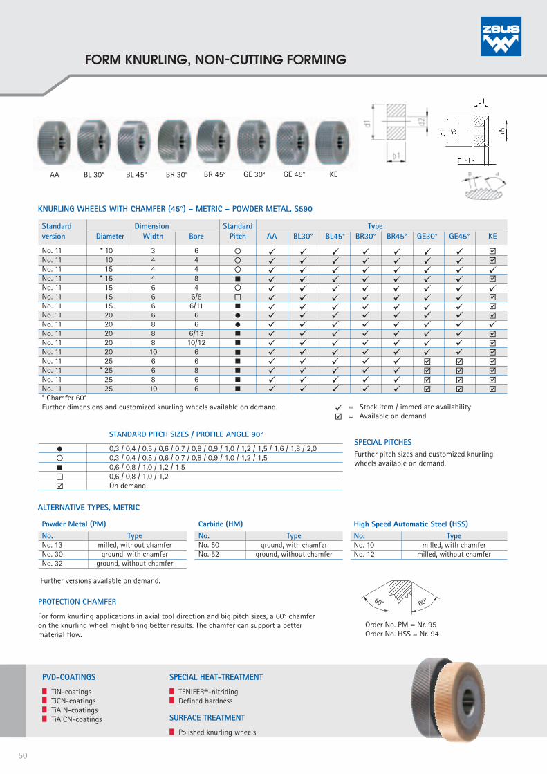
SPECIAL PITCHESFurther pitch sizes and customized knurling wheels available on demand.
0,3 / 0,4 / 0,5 / 0,6 / 0,7 / 0,8 / 0,9 / 1,0 / 1,2 / 1,5 / 1,6 / 1,8 / 2,0 0,3 / 0,4 / 0,5 / 0,6 / 0,7 / 0,8 / 0,9 / 1,0 / 1,2 / 1,5 0,6 / 0,8 / 1,0 / 1,2 / 1,5
0,6 / 0,8 / 1,0 / 1,2 On demand
STANDARD PITCH SIZES / PROFILE ANGLE 90°
Standard Dimension Standard Typeversion Diameter Width Bore Pitch AA BL30° BL45° BR30° BR45° GE30° GE45° KE
No. 11 * 10 3 6 No. 11 10 4 4 No. 11 15 4 4 No. 11 * 15 4 8 No. 11 15 6 4 No. 11 15 6 6/8 No. 11 15 6 6/11 No. 11 20 6 6 No. 11 20 8 6 No. 11 20 8 6/13 No. 11 20 8 10/12 No. 11 20 10 6 No. 11 25 6 6 No. 11 * 25 6 8 No. 11 25 8 6 No. 11 25 10 6 * Chamfer 60° Further dimensions and customized knurling wheels available on demand.
= Stock item / immediate availability = Available on demand
KNURLING WHEELS WITH CHAMFER (45°) – METRIC – POWDER METAL, S590
AA BL 30° BL 45° BR 30° BR 45° GE 30° GE 45° KE
PVD-COATINGS
TiN-coatings TiCN-coatings TiAlN-coatings TiAlCN-coatings
SPECIAL HEAT-TREATMENT
TENIFER®-nitriding Defined hardness
SURFACE TREATMENT
Polished knurling wheels
Powder Metal (PM) No. TypeNo. 13 milled, without chamfer No. 30 ground, with chamfer No. 32 ground, without chamfer
ALTERNATIVE TYPES, METRIC
Carbide (HM)No. TypeNo. 50 ground, with chamfer No. 52 ground, without chamfer
High Speed Automatic Steel (HSS)No. TypeNo. 10 milled, with chamfer No. 12 milled, without chamfer
Further versions available on demand.
PROTECTION CHAMFER
For form knurling applications in axial tool direction and big pitch sizes, a 60° chamfer on the knurling wheel might bring better results. The chamfer can support a better material flow.
Order No. PM = Nr. 95Order No. HSS = Nr. 94
60°60°
50
FORM KNURLING, NON-CUTTING FORMING
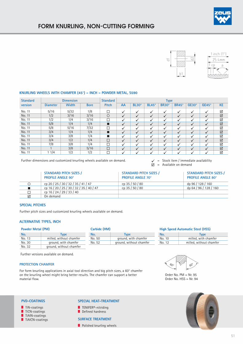
Standard Dimension Standard Typeversion Diameter Width Bore Pitch AA BL30° BL45° BR30° BR45° GE30° GE45° KE
No. 11 5/16 5/32 1/8 No. 11 1/2 3/16 3/16 No. 11 1/2 1/4 3/16 No. 11 5/8 1/4 1/4 No. 11 5/8 5/16 7/32 No. 11 3/4 1/4 1/4 No. 11 3/4 3/8 1/4 No. 11 3/4 1/2 1/4 No. 11 7/8 3/8 1/4 No. 11 1 3/8 5/16 No. 11 1 1/4 1/2 1/2
Further dimensions and customized knurling wheels available on demand. = Stock item / immediate availability = Available on demand
KNURLING WHEELS WITH CHAMFER (45°) – INCH – POWDER METAL, S590
SPECIAL PITCHES
Further pitch sizes and customized knurling wheels available on demand.
cp 20 / 25 / 30 / 32 / 35 / 41 / 47 cp 16 / 20 / 25 / 30 / 32 / 35 / 40 / 47 cp 16 / 24 / 29 / 33 / 40 On demand
cp 35 / 50 / 80 cp 35 / 50 / 80
STANDARD PITCH SIZES /PROFILE ANGLE 90°
STANDARD PITCH SIZES /PROFILE ANGLE 70°
dp 96 / 128 / 160 dp 64 / 96 / 128 / 160
STANDARD PITCH SIZES /PROFILE ANGLE 80°
ALTERNATIVE TYPES, INCH
Further versions available on demand.
PVD-COATINGS
TiN-coatings TiCN-coatings TiAlN-coatings TiAlCN-coatings
PROTECTION CHAMFER
For form knurling applications in axial tool direction and big pitch sizes, a 60° chamfer on the knurling wheel might bring better results. The chamfer can support a better material flow.
Order No. PM = Nr. 95Order No. HSS = Nr. 94
SPECIAL HEAT-TREATMENT
TENIFER®-nitriding Defined hardness
SURFACE TREATMENT
Polished knurling wheels
60°60°
Powder Metal (PM) No. TypeNo. 13 milled, without chamfer No. 30 ground, with chamfer No. 32 ground, without chamfer
Carbide (HM)No. TypeNo. 50 ground, with chamfer No. 52 ground, without chamfer
High Speed Automatic Steel (HSS)No. TypeNo. 10 milled, with chamfer No. 12 milled, without chamfer
51
FORM KNURLING, NON-CUTTING FORMING
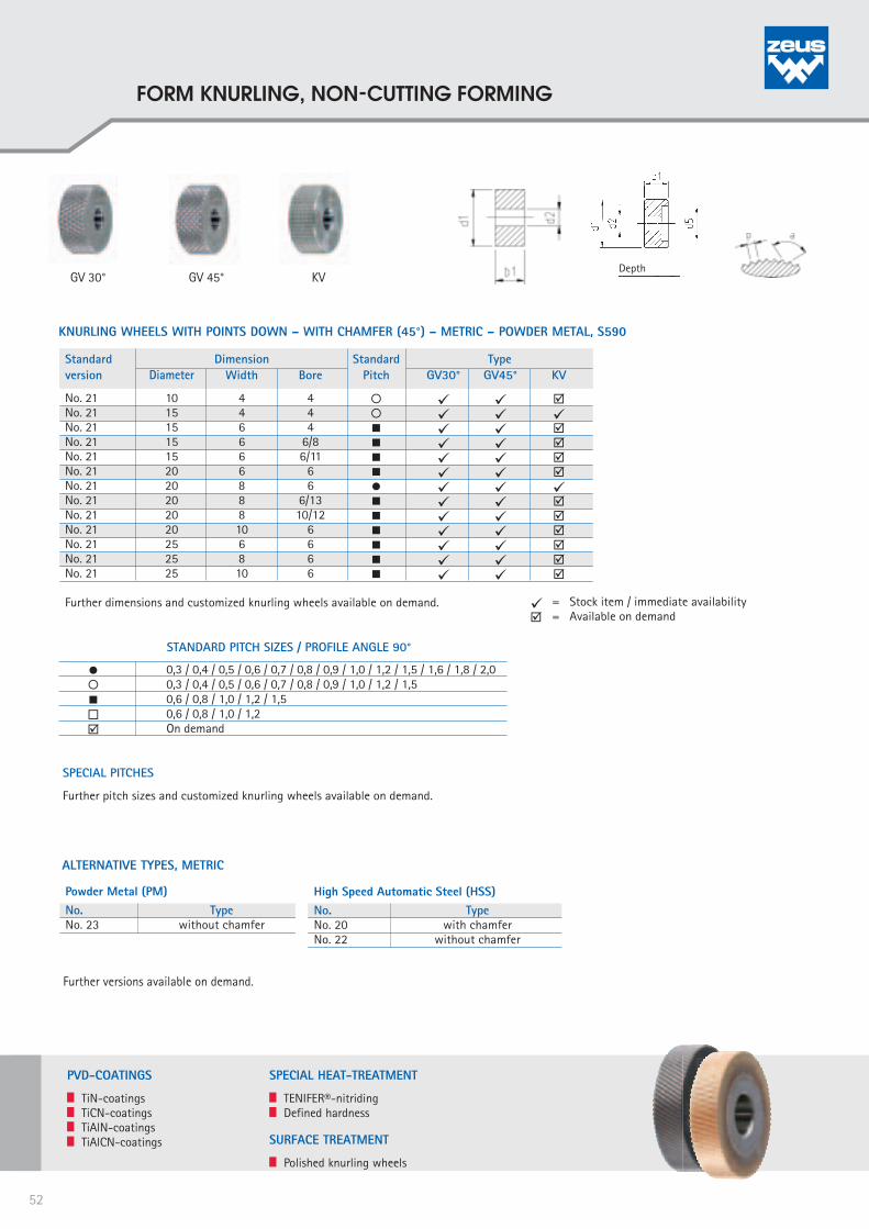
= Stock item / immediate availability = Available on demand
Standard Dimension Standard Type version Diameter Width Bore Pitch GV30° GV45° KV
No. 21 10 4 4 No. 21 15 4 4 No. 21 15 6 4 No. 21 15 6 6/8 No. 21 15 6 6/11 No. 21 20 6 6 No. 21 20 8 6 No. 21 20 8 6/13 No. 21 20 8 10/12 No. 21 20 10 6 No. 21 25 6 6 No. 21 25 8 6 No. 21 25 10 6 Further dimensions and customized knurling wheels available on demand.
KNURLING WHEELS WITH POINTS DOWN – WITH CHAMFER (45°) – METRIC – POWDER METAL, S590
0,3 / 0,4 / 0,5 / 0,6 / 0,7 / 0,8 / 0,9 / 1,0 / 1,2 / 1,5 / 1,6 / 1,8 / 2,0 0,3 / 0,4 / 0,5 / 0,6 / 0,7 / 0,8 / 0,9 / 1,0 / 1,2 / 1,5 0,6 / 0,8 / 1,0 / 1,2 / 1,5
0,6 / 0,8 / 1,0 / 1,2 On demand
STANDARD PITCH SIZES / PROFILE ANGLE 90°
SPECIAL PITCHES
Further pitch sizes and customized knurling wheels available on demand.
GV 30° GV 45° KV
Powder Metal (PM) No. TypeNo. 23 without chamfer
ALTERNATIVE TYPES, METRIC High Speed Automatic Steel (HSS)No. TypeNo. 20 with chamfer No. 22 without chamfer
Further versions available on demand.
PVD-COATINGS
TiN-coatings TiCN-coatings TiAlN-coatings TiAlCN-coatings
SPECIAL HEAT-TREATMENT
TENIFER®-nitriding Defined hardness
SURFACE TREATMENT
Polished knurling wheels
Depth
52
FORM KNURLING, NON-CUTTING FORMING

= Stock item / immediate availability = Available on demand
Standard Dimension Standard Typeversion Diameter Width Bore Pitch AA BL30° BL15° BR30° BR15°
No. 16 8,9 2,5 4 No. 16 10 3 6 No. 16 14,5 3 5 No. 16 15 4 8 No. 16 21,5 5 8 No. 16 25 6 8 No. 16 32 13 16 No. 16 42 13 16 Further dimensions and customized knurling wheels available on demand.
KNURLING WHEEL WITHOUT CHAMFER – METRIC - POWDER METAL, S590
SPECIAL PITCHES
Further pitch sizes and customized knurling wheels available on demand.
0,3 / 0,4 / 0,5 / 0,6 / 0,7 / 0,8 / 0,9 / 1,0 / 1,2 / 1,5 / 1,6 / 1,8 / 2,0 0,3 / 0,4 / 0,5 / 0,6 / 0,7 / 0,8 / 0,9 / 1,0 / 1,2 / 1,5 0,6 / 0,8 / 1,0 / 1,2 / 1,5
0,6 / 0,8 / 1,0 / 1,2 On demand
STANDARD PITCH SIZES / PROFILE ANGLE 90°
AA BL 15° BL 30° BR 15° BR 30°
Powder Metal (PM) No. TypeNo. 18 milled, 10° chamfer No. 35 ground, without chamfer No. 37 ground, 10° chamfer
ALTERNATIVE TYPES, METRIC
Carbide (HM)No. TypeNo. 55 ground, without chamfer No. 57 ground, 10° chamfer
High Speed Automatic Steel (HSS)No. TypeNo. 15 milled, without chamfer No. 17 milled, with chamfer
Further versions available on demand.
PROTECTION CHAMFER
For cut knurling applications difficult to machine materials, a 10° chamfer on the knurling wheel might bring better results. The chamfer can prevent teeth breaking out.
Order No. PM = Nr. 18Order No. HSS = Nr. 17
PVD-COATINGS
TiN-coatings TiCN-coatings TiAlN-coatings TiAlCN-coatings
SPECIAL HEAT-TREATMENT
TENIFER®-nitriding Defined hardness
SURFACE TREATMENT
Polished knurling wheels
10°10°
53
CUT KNURLING, SWARF REMOVAL

NO. 60 – BEAD KNURLING WHEELS
NO. 70 – CONICAL KNURLING WHEELS
NO. 80 – CONVEX / CONCAVE KNURLING WHEELS
NO. 90, 92, 93 – SPECIAL KNURLING WHEELS
HE HHE HV HHV
KAA KBL KBR KGE KGV
C*
NO. 92
DL 20° *
NO. 93
E FL 20° * FR 20° *DR 20° *
NO. 90
Note: The completeness of the teeth numbers on the knurling wheel depends on the width/pitch of the knurl.
Model DL, DR, FL, FR: maximum 20° spiral angle
* With radius < 3 = formed version
With radius > 3 = milled version
Note: Please specify the bead diameter.
d2 d1
b1
R
P
d2
b1
d1ß°
RBb1
d3d2d1
b1
b3b2
d4 d2 d3 d1
RB
dp
b1
d1 d2
p
54
SPECIAL KNURLING WHEELS

zeus® Burnishing rolls can be applied in a standard zeus® form knurling tool. If required, a customer specific bearing system can be developed and produced. These tool systems are suitable for processing cylindrical work pieces, bores, plane sides, conical work pieces and also convex and concave outlines.
ADVANTAGES:
• Burnished work pieces show less friction and increased corrosion resistance
• Subsequent-treatments like grinding, honing or lapping can be easily replaced through roller-burnishing processes
• When used as a supportive roll, the bearing axis and clam-ping devices are less stressed, and the pressure on the work piece is minimized
RESULT:
• Improved surface quality • Increased size accuracy • Strain hardening of the surface
RANGE OF APPLICATION:
zeus® Burnishing rolls are mainly used for roller-burnishing or supporting round material during machining on a lathe.
CHARACTERISTICS:
Material: 1.3343 HSS Hardness: 61-63 HRC
TYPE RRA - CYLINDRICAL
TypeDimension Quality
Ø mm
Widthmm
Boremm
No. 04turned & polished, Rz 4 µm
No. 05ground, Rz 2-3 µm
No. 06ground & polished, Rz 1 µm
RRA
10 4 415 4 420 8 625 8 6
TypeDimension
RQuality
Ømm
Widthmm
Boremm
No. 04turned & polished, Rz 4 µm
No. 05ground, Rz 2-3 µm
No. 06ground & polished, Rz 1 µm
RRE
10 4 4 215 4 4 420 8 6 625 8 6 6
TYP RRE - KONVEX
55
BURNISHING ROLLS

Work piece Marking roll
S SL SR SLR W WL WR WLR
Com
plet
e w
indu
p
Marking typeson work piece:
CONTINUOUS ROLL MARKING – ZEUS® MARKING ROLL NO. 40
Work piece Marking rollMarking typeson work piece:
Com
plet
e w
indu
p
Cont
act o
f the
roll
S W
SPRING RETURN MARKING – ZEUS® MARKING ROLL NO. 41
Work piece Marking roll
Com
plet
e w
indu
pCo
ntac
t of t
he ro
ll
ExchangeableSegments
Marking typeson work piece:
S W
SPRING RETURN MARKING – ZEUS® MARKING ROLL NO. 42
For detailed information please request the zeus® Marking Technique catalogue.
zeus® ENGRAVING TECHNOLOGY
The zeus® engraving technology covers a wide range of applications. It includes manual stamps, circular stamps and engravings, marking rollers and machine stamps for labelling, branding and decorating turned-parts, work pieces and plates of a variety of materials. Each engraving tool is individually designed and manufactured.
CONTINUOUS ROLL MARKING – ZEUS® MARKING ROLL NO. 40-A
Work piece Marking roll
S SL SR SLR W WL WR WLR
Marking typeson work piece:
56
zeus® MARKING ROLLS/ENGRAVING TECHNOLOGY
TECHNICAL APPENDIX
CONTENT
MATERIAL DISPLACEMENT
SPEED / FEED RATES
KNURLING OPTIMIZATION
CONVERSION TABLE
INFLUENCING FACTORS

Our experience values for the increase in work piece diameter through form knurling
Knurling profile according to DIN 82: RAA (Profile on work piece) Knurling wheels according to DIN 403: AA (Profile for knurling wheels) RAA
Knurling profile according to DIN 82: RBL 30°/RBR 30° (Profile on work piece)Knurling wheels according to DIN 403: BR 30°/BL 30° (Profile for knurling wheels) RBL 30° RBR 30°
Knurling profile according to DIN 82: RGE 30° (Profile on work piece)Knurling wheels according to DIN 403: BR 30° + BL 30° (Profile for knurling wheels)
Pitch 0,3 0,4 0,5 0,6 0,7 0,8 0,9 1,0 1,2 1,5 1,6 1,8 2,0Material Work piece-Ø Increase in work piece diameter-ø in mmFree-cutting Steel 5 0,08 0,14 0,18 0,22 0,27 0,29 0,33 0,35 0,50 - - - - 15 0,08 0,14 0,18 0,23 0,30 0,40 0,41 0,44 0,50 0,60 0,65 0,67 0,70 25 0,08 0,15 0,23 0,24 0,28 0,35 0,38 0,44 0,53 0,62 0,70 0,70 0,98Stainless Steel 5 0,10 0,15 0,20 0,25 0,28 0,30 0,35 0,42 0,41 - - - - 15 0,10 0,15 0,19 0,25 0,30 0,34 0,40 0,45 0,51 0,60 - - - 25 0,10 0,14 0,20 0,26 0,31 0,33 0,38 0,43 0,50 0,62 - - -Brass 5 0,08 0,12 0,18 0,20 0,21 0,22 0,23 0,25 0,28 - - - - 15 0,10 0,14 0,20 0,26 0,28 0,29 0,31 0,35 0,41 0,44 0,48 0,50 0,55 25 0,10 0,15 0,20 0,25 0,28 0,30 0,32 0,36 0,43 0,46 0,50 0,53 0,53Aluminium 5 0,09 0,15 0,19 0,23 0,28 0,30 0,34 0,41 0,40 - - - - 15 0,10 0,15 0,19 0,26 0,29 0,33 0,39 0,45 0,51 0,57 0,65 - - 25 0,09 0,15 0,19 0,26 0,29 0,32 0,37 0,45 0,52 0,59 0,65 0,78 0,75
Pitch 0,3 0,4 0,5 0,6 0,7 0,8 0,9 1,0 1,2 1,5 1,6 1,8 2,0Material Work piece-Ø Increase in work piece diameter-ø in mmFree-cutting Steel 5 0,11 0,15 0,20 0,24 0,28 0,34 0,38 0,45 0,55 - - - - 15 0,11 0,15 0,22 0,26 0,30 0,35 0,42 0,45 0,52 0,67 0,73 0,75 0,85 25 0,11 0,14 0,23 0,25 0,28 0,36 0,42 0,45 0,56 0,70 0,72 0,78 0,90Stainless Steel 5 0,09 0,14 0,19 0,25 0,31 0,34 0,39 0,45 0,52 - - - - 15 0,12 0,20 0,23 0,31 0,35 0,40 0,45 0,51 0,62 0,66 0,73 0,85 0,97 25 0,12 0,18 0,24 0,27 0,37 0,39 0,43 0,49 0,59 0,80 0,84 0,93 0,96Brass 5 0,10 0,14 0,20 0,23 0,24 0,28 0,30 0,33 0,37 - - - - 15 0,10 0,15 0,21 0,23 0,24 0,31 0,36 0,41 0,47 0,53 0,55 0,64 0,63 25 0,11 0,15 0,22 0,22 0,25 0,30 0,35 0,40 0,45 0,55 0,61 0,62 0,68Aluminium 5 0,12 0,14 0,21 0,24 0,29 0,34 0,39 0,41 0,51 - - - - 15 0,12 0,18 0,23 0,26 0,36 0,40 0,43 0,50 0,56 0,56 0,61 0,74 0,75 25 0,12 0,16 0,25 0,28 0,37 0,39 0,46 0,50 0,58 0,77 0,82 0,84 0,96
Pitch 0,3 0,4 0,5 0,6 0,7 0,8 0,9 1,0 1,2 1,5 1,6 1,8 2,0Material Work piece-Ø Increase in work piece diameter-ø in mmFree-cutting Steel 5 0,12 0,16 0,20 0,25 0,33 0,41 0,45 0,55 0,65 - - - - 15 0,13 0,22 0,30 0,32 0,35 0,41 0,43 0,52 0,62 0,67 0,81 0,86 0,95 25 0,12 0,18 0,28 0,32 0,35 0,38 0,43 0,55 0,67 0,77 0,87 0,98 0,98Stainless Steel 5 0,11 0,20 0,25 0,30 0,36 0,39 0,41 0,55 0,55 - - - - 15 0,10 0,14 0,21 0,24 0,29 0,34 0,40 0,43 0,53 0,66 0,72 0,70 0,88 25 0,11 0,13 0,20 0,25 0,28 0,32 0,41 0,44 0,52 0,67 0,70 0,71 0,83Brass 5 0,12 0,13 0,16 0,20 0,24 0,28 0,30 0,32 0,38 - - - - 15 0,12 0,16 0,18 0,24 0,28 0,30 0,37 0,39 0,40 0,48 0,52 0,55 0,63 25 0,12 0,17 0,22 0,23 0,27 0,30 0,34 0,38 0,41 0,48 0,50 0,63 0,63Aluminium 5 0,10 0,15 0,21 0,25 0,33 0,36 0,41 0,50 0,57 - - - - 15 0,11 0,14 0,20 0,25 0,28 0,33 0,39 0,43 0,54 0,67 0,71 0,76 0,89 25 0,11 0,15 0,22 0,25 0,29 0,34 0,40 0,44 0,53 0,68 0,69 0,71 0,88
RGE 30°
Note: These values are guidelines only. Minor deviations may occur depending on material. Applies only to form knurling.58
MATERIAL DISPLACEMENT THROUGH FORM KNURLING
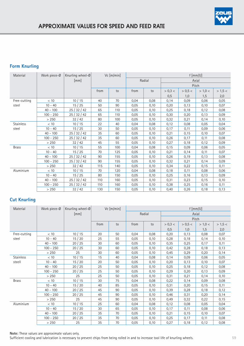
Cut Knurling
Note: These values are approximate values only.Sufficient cooling and lubrication is necessary to prevent chips from being rolled in and to increase tool life of knurling wheels.
Form Knurling
Material Work piece-Ø Knurling wheel-Ø Vc [m/min] f [mm/U] [mm] Radial Axial Pitch from to from to > 0,3 < > 0,5 < > 1,0 < > 1,5 < 0,5 1,0 1,5 2,0Free-cutting < 10 10 / 15 40 70 0,04 0,08 0,14 0,09 0,06 0,05 steel 10 - 40 15 / 25 50 90 0,05 0,10 0,20 0,13 0,10 0,07 40 - 100 25 / 32 / 42 65 110 0,05 0,10 0,25 0,18 0,12 0,08 100 - 250 25 / 32 / 42 65 110 0,05 0,10 0,30 0,20 0,13 0,09 > 250 32 / 42 80 100 0,05 0,10 0,32 0,21 0,14 0,10 Stainless < 10 10 / 15 22 40 0,04 0,08 0,12 0,08 0,05 0,04 steel 10 - 40 15 / 25 30 50 0,05 0,10 0,17 0,11 0,09 0,06 40 - 100 25 / 32 / 42 35 60 0,05 0,10 0,21 0,15 0,10 0,07 100 - 250 25 / 32 / 42 35 60 0,05 0,10 0,26 0,17 0,11 0,08 > 250 32 / 42 45 55 0,05 0,10 0,27 0,18 0,12 0,09 Brass < 10 10 / 15 55 100 0,04 0,08 0,15 0,09 0,06 0,05 10 - 40 15 / 25 70 125 0,05 0,10 0,21 0,14 0,11 0,07 40 - 100 25 / 32 / 42 90 155 0,05 0,10 0,26 0,19 0,13 0,08 100 - 250 25 / 32 / 42 90 155 0,05 0,10 0,32 0,21 0,14 0,09 > 250 32 / 42 115 140 0,05 0,10 0,34 0,22 0,15 0,11 Aluminium < 10 10 / 15 70 120 0,04 0,08 0,18 0,11 0,08 0,06 10 - 40 15 / 25 80 150 0,05 0,10 0,25 0,16 0,13 0,09 40 - 100 25 / 32 / 42 110 160 0,05 0,10 0,31 0,23 0,15 0,10 100 - 250 25 / 32 / 42 110 160 0,05 0,10 0,38 0,25 0,16 0,11 > 250 32 / 42 130 150 0,05 0,10 0,40 0,26 0,18 0,13
Material Work piece-Ø Knurling wheel-Ø Vc [m/min] f [mm/U] [mm] Radial Axial Pitch from to from to > 0,3 < > 0,5 < > 1,0 < > 1,5 < 0,5 1,0 1,5 2,0Free-cutting < 10 10 / 15 20 50 0,04 0,08 0,20 0,13 0,08 0,07 steel 10 - 40 15 / 20 25 55 0,05 0,10 0,28 0,18 0,14 0,10 40 - 100 20 / 25 30 60 0,05 0,10 0,35 0,25 0,17 0,11 100 - 250 20 / 25 30 60 0,05 0,10 0,42 0,28 0,18 0,13 > 250 25 30 60 0,05 0,10 0,45 0,29 0,20 0,14Stainless < 10 10 / 15 15 40 0,04 0,08 0,14 0,09 0,06 0,05 steell 10 - 40 15 / 20 20 50 0,05 0,10 0,20 0,13 0,10 0,07 40 - 100 20 / 25 25 50 0,05 0,10 0,25 0,18 0,12 0,08 100 - 250 20 / 25 25 50 0,05 0,10 0,29 0,20 0,13 0,09 > 250 25 25 50 0,05 0,10 0,31 0,21 0,14 0,10 Brass < 10 10 / 15 30 75 0,04 0,08 0,22 0,14 0,09 0,08 10 - 40 15 / 20 40 85 0,05 0,10 0,31 0,20 0,15 0,11 40 - 100 20 / 25 45 90 0,05 0,10 0,39 0,28 0,18 0,12 100 - 250 20 / 25 45 90 0,05 0,10 0,46 0,31 0,20 0,14 > 250 25 45 90 0,05 0,10 0,49 0,32 0,22 0,15 Aluminium < 10 10 / 15 25 60 0,04 0,08 0,12 0,08 0,05 0,04 10 - 40 15 / 20 30 65 0,05 0,10 0,17 0,11 0,08 0,06 40 - 100 20 / 25 35 70 0,05 0,10 0,21 0,15 0,10 0,07 100 - 250 20 / 25 35 70 0,05 0,10 0,25 0,17 0,11 0,08 > 250 25 35 70 0,05 0,10 0,27 0,18 0,12 0,08
59
APPROXIMATE VALUES FOR SPEED AND FEED RATE

The exact relation of the number of teeth to work piece circumference is a significant factor influencing the knurling result and tool life. For many end-users this factor is more or less unknown and is therefore often neglected when it comes down to knurling optimization methods. In practice it is a common mistake to determining the pitch without considering the dependence of the work piece circumference. The consequences on the knurling result and tool life can be considerable, though. The following discussion explains the context between pitch and work piece circumference and provides systematic proceedings for optimization of the knurling profile.
1. The relation between number of teeth and work piece circumference is almost exact
In many cases, the end-user does not notice much of the issue discussed, as the relation between number of teeth and work piece diameter is already sufficiently exact. In this case, the knurling wheel is able to equalize the deformation of the pitch, so that a clean profile can be produced (see also figure 1).
2. The relation between number of teeth and work piece circumference is not optimal
With an increasing imbalance of the relation between number of teeth and work piece circumference, the knurling wheel has to equalize the imbalance. As a result the quality of the knurling profile is diminished and the tool life is decreased.
3. The relation between number of teeth and work piece circumference is insufficient
If the relation between number of teeth and work piece circumference is insufficiently precise, the knurling wheel can no longer equalize the imbalance resulting in a deformation of the profile.
In the worst case, a double knurl might arise as a consequence, as the knurling wheel does not return exactly into the knurling profile after the first work piece rotation. The problem can also be recognized from the finer pitch of the knurling profile (see also figure 3).
The effects of this process for the two different knurling techniques can be summarized as follows:
Form Knurling: Here, the deformation process (as the material is compressed during forming) leads to a rough surface and a decrease in tool life. Through the deterioration of the penetration process, material abrasion occurs, which is consequently formed into the material. A distortion of the knurling profile takes place, which is recognizable as a flatter profile and a rounding off of the teeth tips (see also figure 2).
Cut Knurling: The deterioration of the penetrationprocess leads to unclean profile flanks. A distorted knurling profile results, recognizable from the flattening of the profile and the rounding in the tooth form / the teeth tips (see also figure 2).
Figure 1:Optimal knurling profile
Figure 3:Double knurling profile
Figure 2:Distorted knurling profile
60
KNURLING OPTIMIZATION

An optimization of the knurling profile can take place through adjustment of either the pre-turning diameter or the pitch.Both optimization methods can result in a better knurling quality and an increased tool life.
A systematic optimization approachincludes the following steps:
→ Correction of the pre-turning diameter until an optimum knurl quality is achieved.
Note: Even a small change of less than 1/100 mm of the pre-turning diameter affects the work piece circumference consider-ably {factor π (x 3,14...)} and can lead to a significant improvement of the knurling quality.
If a correction of the pre-turning diameter is not possible because tolerances cannot be kept:
→ Adjust pitch size
Summary:
The customer requirements are:
• A clean, fully formed knurling profile
• Fully formed teeth
• No double knurling profile
• Work piece with defined number of teeth
If the pitch cannot be adjusted, the manufacture of a special wheel with a predefined pitch (defined number of teeth / work piece outer diameter) is necessary.
The Hommel + Keller application technicians will give the necessary advice and consultation by means of a work piece drawing and the machine specifications. The calcula-tion of the optimum number of teeth takes place on the basis of approxi-mation formulas. Due to a number of influencing variables, such as material characteristics, a further optimization approach might involve an application specific test series.
Solutions:
1) Optimization measures by end-user:1.1 Correction of pre-turning diameter1.2 Adjustment of pitch
2) Optimization measures by Hommel + Keller Präzisionswerkzeuge GmbH:
Optimization through design of a special knurling wheel: By calculating the number of teeth, the knurling wheel is adjusted to the specific application through an optimum relation between diameter and teeth number. With this approach knurling wheels with a defined number of teeth can also be manufactured.
61
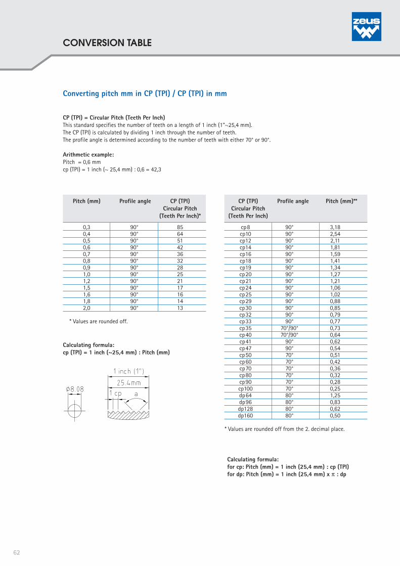
Converting pitch mm in CP (TPI) / CP (TPI) in mm
CP (TPI) = Circular Pitch (Teeth Per Inch)This standard specifies the number of teeth on a length of 1 inch (1“~25,4 mm). The CP (TPI) is calculated by dividing 1 inch through the number of teeth. The profile angle is determined according to the number of teeth with either 70° or 90°.
Arithmetic example:Pitch = 0,6 mmcp (TPI) = 1 inch (~ 25,4 mm) : 0,6 = 42,3
Calculating formula: cp (TPI) = 1 inch (~25,4 mm) : Pitch (mm)
Pitch (mm) Profile angle CP (TPI) Circular Pitch (Teeth Per Inch)*
0,3 90° 85 0,4 90° 64 0,5 90° 51 0,6 90° 42 0,7 90° 36 0,8 90° 32 0,9 90° 28 1,0 90° 25 1,2 90° 21 1,5 90° 17 1,6 90° 16 1,8 90° 14 2,0 90° 13
* Values are rounded off.
Calculating formula: for cp: Pitch (mm) = 1 inch (25,4 mm) : cp (TPI)for dp: Pitch (mm) = 1 inch (25,4 mm) x π : dp
CP (TPI) Profile angle Pitch (mm)** Circular Pitch (Teeth Per Inch)
cp8 90° 3,18 cp10 90° 2,54 cp12 90° 2,11 cp14 90° 1,81 cp16 90° 1,59 cp18 90° 1,41 cp19 90° 1,34 cp20 90° 1,27 cp21 90° 1,21 cp24 90° 1,06 cp25 90° 1,02 cp29 90° 0,88 cp30 90° 0,85 cp32 90° 0,79 cp33 90° 0,77 cp35 70°/90° 0,73 cp40 70°/90° 0,64 cp41 90° 0,62 cp47 90° 0,54 cp50 70° 0,51 cp60 70° 0,42 cp70 70° 0,36 cp80 70° 0,32 cp90 70° 0,28 cp100 70° 0,25 dp64 80° 1,25 dp96 80° 0,83 dp128 80° 0,62 dp160 80° 0,50
* Values are rounded off from the 2. decimal place.
62
CONVERSION TABLE

b
b
a
Factors influencing profile quality and process rigidity for knurling applications
Distance dimension / Clearance groove Cut Knurling
For a high quality and functionally immaculate knurling profile, there are a number of factors that should be consideredand if necessary improved in order to optimize the overall end-result:
Tool characteristics
Machine characteristics
Characteristics of the material processed Application specific characteristics
Quality and specificationof the knurling wheel
Type of knurling tool
PrecisionStability / no vibrationsHardnessToughness
Speed ratePlunge depthCooling / LubricationClearance angleQuality of the gearing
Knurling wheel widthKnurling wheel with chamferMaterial characteristics
Precision
Applied knurlingtechnique
Quality and conditionof the knurling pin /run diskStability /no vibrationsPrecision
Feed rateSpeed rate
Pre-turning diameterPitch / Number of teethMaterial displacement
Material of theknurling wheelHardness of the knurling wheelAfter-treatment
Truth of runningConcentricityProfile characteristics
Form knurling
Cut knurling
PVD-coatingTENIFER®-TREATMENT
Sharpness of the tooth tipsRadius in the tooth depthProfile anglePlunge knurlingFeed knurlingPlunge and feed knurling
Minimum distance towards work piece shoulder Due to the inclination of the cut knurling head (30°) and the overhang of the washer, it is not possible to knurl up to a shoulder with a cut knurling tool.
Please adhere to the minimum distance values given in the tablea = increase in shoulder (mm)b = minimum distance (ø) in mm
Minimum width of groove In order to start the knurling profile in the middle of the work piece, a groove is required (knurling wheel requires a chamfer for centering). Minimum depth of groove: ½ pitch +0,3 mm
Measure b (10x3x6) b (15x4x8) b (25x6x8) b (42x13x16) "a" 1 2 1,5 2 3 3 2,5 3,5 3 5 5 3 6 5 7 7 8 9 10 12 12 13
Dimensions knurling 10x3x6 15x4x8 26x6x8 42x13x6 wheel Minimum width of 3 mm 4 mm 6,5 mm 14 mmgroove [b]
63
INFLUENCING FACTORS
Hommel+Keller Präzisionswerkzeuge GmbHBrunnenstraße 36 . D-78554 Aldingen
Art.
-No
. 08K
AT0
033
/ 10
.201
0 /
4. E
diti
on
. Te
ch
nic
al d
eta
ils a
re s
ub
jec
t to
ch
an
ge
. Prin
ting
err
ors
exc
ep
ted
. ©
No
pa
rt o
f th
ese
do
cu
me
nt m
ay
be
co
pie
d o
r dis
clo
sed
for a
ny p
urp
ose
s w
itho
ut t
he
writ
ten
ap
pro
val
of H
om
me
l+Ke
ller P
räzi
sio
nsw
erk
zeu
ge
Gm
bH
. All
righ
ts re
serv
ed
.
Phone +49 (0) 74 24/97 05-0Fax +49 (0) 74 24/97 05-50
THE HOMMEL+KELLER PRÄZISIONSWERKZEUGE GMBH
IS PART OF THE HOMMEL + KELLER GROUP.
The Hommel + Keller group off ers all fi elds of metal working processing, combined with modern heat treatments and high-tech PVD-coatings out of one unit. Benefi t from the synergies resulting from the close cooperation between our three companies!
HOMMEL+KELLER PRÄZISIONSWERKZEUGE GMBHH+K HÄRTE- UND OBERFLÄCHENTECHNIK GMBHH+K SURFACE TECHNOLOGY GMBHH+K CARBOTEC GMBH