Zero Emission Porto Tolle (ZEPT) Project - CSLF · 18.04.2013 · include DIC, DOC and inorganic...
45
Silvana Iacobellis Enel Ingegneria & Ricerca S.p.A. Ricerca Roma, April 18th 2013 Zero Emission Porto Tolle (ZEPT) Project
Transcript of Zero Emission Porto Tolle (ZEPT) Project - CSLF · 18.04.2013 · include DIC, DOC and inorganic...

Silvana Iacobellis
Enel Ingegneria & Ricerca S.p.A.
Ricerca
Roma, April 18th 2013
Zero Emission Porto Tolle (ZEPT) Project

Uso: Aziendale
2 Rome, April 18th 2013
Porto Tolle CCS Demo Project
Project developer: ENEL
Power plant: • Retrofit of oil-fired power plant to 3 USC
coal-fired units of 660 MWe
Capture • Retrofit of a stream of 660MW unit:
250MWe (net) post-combustion.
Transport • 100-150km off-shore pipeline.
Storage • Deep saline aquifer.
• 25 km offshore.
• ~1 MtCO2/yr.

Uso: Aziendale
3 Rome, April 18th 2013
Porto Tolle CCS Demo project update
Pilot in Brindisi has run over 5,000 hrs (promising results in the energy consumption and environmental results).
Capture: FEED Study – completed
Transport: Engineering – on going.
Injection: Feasibility studies for subsurface structure and injection system - completed.
Feed for platform and well(s) – to be started.
Storage: Site Selection – completed
• Modelling of storage site – completed
• Baseline area characterization – completed
• Environmental Impact studies for the appraisal well execution – completed
Transposition of Storage Directive accomplished; delays in technical decrees implementation

Uso: Aziendale
4 Rome, April 18th 2013
Porto Tolle CCS Demo project Permitting process update
In May 2011 the State Council of Italy decided to void the Environmental Authorization (EIA).
new Environmental Impact Assessment to be submitted
delays in the reconversion to coal and inevitable and inestimable delays in the commissioning of the CCS Demo Project

Rome, April 18th 2013
Uso: Aziendale
Site selection and
characterization
Site preparation and well
construction
Operation and performance assessment
Closure and post closure
management
(~10-50 years) Storage permit
Project develpment plan Site preparation Site construction
Injection
(~2-5 years) Site screening Site selection
Exploration permit Site characterization
(~100-1000 years) Storage Closure permit
Decomissioning Site closure certificate
Transfer of liability
Monitoring
Performance & Risk Assessment
Communication and Public Acceptance
The monitoring: a transversal need
Monitoring is one of the key activities to ensure the safety of geological storage as required by the CCS Directive and ETS Directive.
It is essential to assess whether injected CO2 is behaving as expected, whether any migration or leakage occurs, and whether any identified leakage is influencing the environment or human health
5

Rome, April 18th 2013
Uso: Aziendale
DIRECTIVE 2009/31/EC on the geological storage of carbon dioxide art. 13 Monitoring e Annex II
The monitoring plan shall provide details of the monitoring to be deployed at the main stages of the project, including baseline, operational and post-closure monitoring. The following shall be specified for each phase: (a) parameters monitored; (b) monitoring technology employed and justification for
technology choice; (c) monitoring locations and spatial sampling rationale; (d) frequency of application and temporal sampling rationale.
6

Rome, April 18th 2013
Uso: Aziendale
Baseline Why?
Pre-injection measurements provide a general overview of the characteristics and peculiarities of the studied area.
The goal of this investigation is dual: identification of areas where it will be more likely to observe any leakage
of CO2 and then planning of the continuous monitoring network where you will need to focus,
obtain a database indicative of background values typical of the area and their natural variability.
The proper knowledge of the baseline is in fact important in the interpretation of data obtained from monitoring. The studied variables are characterized natural oscillations related to seasonality, but also by the periodic variation of intensity in the migration of endogenous gases.
7
Rome, April 18th 2013
Uso: Aziendale
8
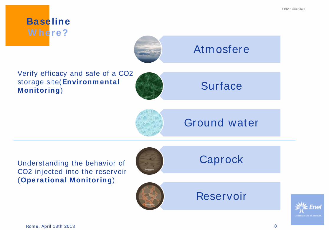
Baseline Where?
Verify efficacy and safe of a CO2 storage site(Environmental Monitoring) Understanding the behavior of CO2 injected into the reservoir (Operational Monitoring)
Atmosfere
Surface
Ground water
Caprock
Reservoir

Rome, April 18th 2013
Uso: Aziendale
Baseline Where?
9
Storage complex: the storage site and surrounding geological domain which can have an effect on overall storage integrity and security; that is, secondary containment formations

Rome, April 18th 2013
Uso: Aziendale
Baseline What?
Evaluation of formation gas and fluid characteristics in the storage reservoir and the surrounding area that might be affected by potential leakage, including aquifers;
Measurements of background CO2 emissions at surface or sea floor; Surface and near surface environmental surveys; Seabed, surface or near surface baseline surveys to define any pre-existing
leakage indicators such as pock marks; Ground surface surveying, where ground movement can be a risk
10

Rome, April 18th 2013
Uso: Aziendale
11
Best Practices
The "new" approach is to share a methodology in order to ensure a common work flow.
11

Rome, April 18th 2013
Uso: Aziendale
Design of an site monitoring program
1. Review all available proven and potential monitoring technologies.
2. Select which particular techniques are required to achieve the
required objectives.
3. Design appropriate field deployment parameters to achieve
effective monitoring.
This final step will in all likelihood require significant modeling work,
including a comprehensive sensitivity analysis.
12

Rome, April 18th 2013
Uso: Aziendale
Potential monitoring tools
13
Rome, April 18th 2013
Uso: Aziendale
14
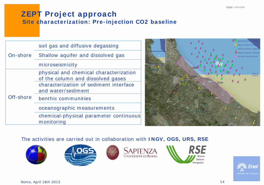
ZEPT Project approach Site characterization: Pre-injection CO2 baseline
On-shore
soil gas and diffusive degassing
Shallow aquifer and dissolved gas
microseismicity
Off-shore
physical and chemical characterization of the column and dissolved gases characterization of sediment interface and water/sediment
benthic communities
oceanographic measurements
chemical-physical parameter continuous monitoring
The activities are carried out in collaboration with INGV, OGS, URS, RSE

Rome, April 18th 2013
Uso: Aziendale
Pre-injection off-shore survey
The baseline study covers a ∼ 400 km2
area around the more probable injection
locations in water depths ranging from
13 to 40 m.
Measurements include chemical,
biological and physical analyses of both
the water column and the near-surface
sediments during four different periods
of the year to define the ranges of
baseline values in the area, both spatially
and temporally.
15

Rome, April 18th 2013
Uso: Aziendale
What effects on the marine ecosystem?
pH and pCO2
biogeochemical carbon cycle
diagenetic processes
mobilization of pollutants in
sediments deposited
processes of production and
respiration
physiology
calcification in different
organisms
…
16
Courtesy of OGS-CO2GeoNet

Rome, April 18th 2013
Uso: Aziendale
The increase of CO2 in seawater reduces the availability of carbonate ions necessary for marine calcifying organisms such as corals, molluscs, echinoderms and crustaceans
to produce their skeletons or shells of their CaCO3
Rodolfo-Metalpa et al. 2011
Figure 4 Underwater and scanning electron microscopy images of B. europaea transplanted along a CO2 gradient off Ischia. a–f, Live coral after seven months at mean pHT 8.1 (a–c) and 7.3 (d–f). g–i, Dead coral after three months at
mean pHT 7.3 (Supplementary Table S2a). Details of the outer corallite wall showing normal skeleton when covered (Co) in tissue (b,e) and
dissolved skeleton when uncovered (Un) in tissue (h) . Enlargements (yellow boxes on b, e,
h) show organized (c,f) and dissolved (i) bundles of aragonite crystals. Scale bars: 1 cm
(a,d,g), 100 µm (b,e,h) and 1 µm (c,f,i).
Effect on organism
17

Rome, April 18th 2013
Uso: Aziendale
V. J. Fabry et al. 2008
In addition to calcification, the increase of pCO2 influence a number of other
physiological processes associated with adjustment mechanisms such as acid-base survival, growth, development, metabolism
Examples of the response of marine fauna to acidification

Rome, April 18th 2013
Uso: Aziendale
Box corer which was used to collect sediment samples for
microphytobenthos and meiobenthos. Macrozoobenthos
Benthos census
The abundance and biodiversity of the autotrophic and heterotrophic benthic communities was analysed on a subset of stations during 2 of the campaigns (winter and summer) in order to characterize the present status of the ecosystem and, possibly, to identify the most sensitive
species.
For macrobenthos determinations, three replicate samples will be collected in a grid of selected stations across the investigated area. Grab samples will be collected and all
organisms retained in 1 mm mesh sieves will be fixed and preserved in formaldehyde-seawater solution until the
successive determination. Other benthic communities will be subsampled from cores.
19

Rome, April 18th 2013
Uso: Aziendale
19 to 20, 30 cm long box cores were collected during each cruise and 10-20 cm of the overlying bottom water (supernatant), with all cores being extruded
and sub-sampled at the site.
Discontinuous sediment cores sampling
20

Rome, April 18th 2013
Uso: Aziendale
Chemical/biochemical measurements in sediment cores
For the analyses of porewater components, sediment slices from the extruded core will be centrifuged, and the interstitial waters analysed for a series of parameters. Comparison of these results with the supernatant results will allow for the calculation of diffusive fluxes. Analyses will include DIC, DOC and inorganic nutrients, Eh and total organic carbon and nitrogen, chlorophyll a, major elements, and selected trace elements. Depending on sediment grain size, also H2S porewater analyses will be performed. Moreover, selected samples will be analysed for δ13C on organic matter and DIC. The stable 13C isotopic composition of DIC (13CDIC), in fact, could be used as a sensitive indicator of processes affecting the production of DIC because the 13C composition of sedimentary organic matter differs significantly from that of carbonates and DIC in the bottom water layer. In general, dissolution of carbonates would add DIC enriched in 13C with respect to the sedimentary organic matter.
21

Rome, April 18th 2013
Uso: Aziendale
Water column sampling – discontinuous measurements
Bottom water samples were collected from 10 (or more) sampling stations using Niskin bottles mounted together with a CTD probe for conductivity, temperature,
pressure, fluorescence, pH and dissolved O2 measurements.
Water samples were analyzed for pH, dissolved inorganic and organic carbon (DIC, DOC), alkalinity, dissolved O2, chlorophyll a (chl a), particulate organic carbon and nitrogen (POC, PON), inorganic nutrients (phosphate, nitrate, nitrite, ammonium, silicate), major elements and selected trace elements. Moreover, on selected samples δ13C analyses were performed on organic matter and carbonates, in order to investigate their origin.
22
Rome, April 18th 2013
Uso: Aziendale
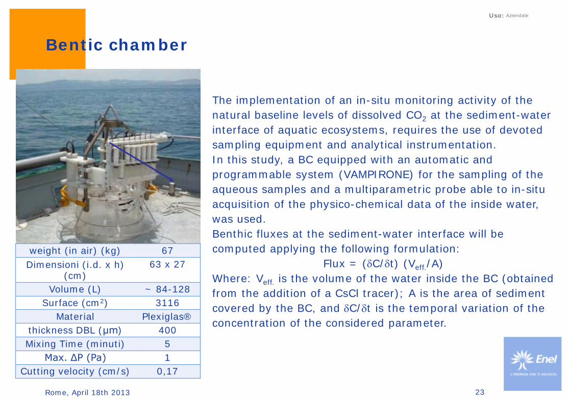
weight (in air) (kg) 67 Dimensioni (i.d. x h)
(cm) 63 x 27
Volume (L) ~ 84-128
Surface (cm2) 3116
Material Plexiglas®
thickness DBL (μm) 400
Mixing Time (minuti) 5
Max. ΔP (Pa) 1
Cutting velocity (cm/s) 0,17
The implementation of an in-situ monitoring activity of the natural baseline levels of dissolved CO2 at the sediment-water interface of aquatic ecosystems, requires the use of devoted sampling equipment and analytical instrumentation. In this study, a BC equipped with an automatic and programmable system (VAMPIRONE) for the sampling of the aqueous samples and a multiparametric probe able to in-situ acquisition of the physico-chemical data of the inside water, was used. Benthic fluxes at the sediment-water interface will be computed applying the following formulation:
Flux = (δC/δt) (Veff./A) Where: Veff. is the volume of the water inside the BC (obtained from the addition of a CsCl tracer); A is the area of sediment covered by the BC, and δC/δt is the temporal variation of the concentration of the considered parameter.
Bentic chamber
23

Rome, April 18th 2013
Uso: Aziendale
In order to define the chemical speciation of the dissolved CO2 in seawater, an analytical technique based on the Flow Injection Analysis (FIA) coupled with a gas diffusion
semipermeable membrane (GD) and a conductometric micro detector, was developed.
GD-FIA/Conductometry Analyser
This instrumentation is able to determine low levels of CO2 both as dissolved (solvated) gaseous molecular form (CO2aq) and as total Dissolved Inorganic Carbon (DIC) integrated parameter, simply injecting in the analyser the untreated and the acidified seawater sample. Besides, the need for carrying out the measurements just after the recovery of the samples, in order to minimize their alterations, imposes that the analytical determinations must be performed on board. This constraint, in his turn, imposes the availability of analytical instrumentation that, as well as assuring suitable analytical performance, has to be small sized, transportable and sturdy.
24

Rome, April 18th 2013
Uso: Aziendale
The analytical techniques used for the measurements of the considered parameters were the following:
Potentiometric titration (TAlk) Flame Emission Spectrometry (FES), Atomic Absorption Spectrometry (AAS), and
Inductively Coupled Plasma - Atomic Emission Spectrometry (ICP-AES) (metals) CHN elemental analyser (TC, TH and TN) Accelerator Mass Spectrometry (AMS) (δ13CDIC and Δ14CDIC in the DIC) Continuous Flow - Isotope Ratio Mass Spectrometry (CF-IRMS) (δ13CSOM and δ15NSOM,
Corgtot (TOC) and TN in the SOM) Automated UV-Vis Spectrophotometry (Autoanalyzer) (nutrients) High Performance Liquid Chromatography (HPLC) (Cl, SO4) Sieves and X-rays sedigraph analyser (grain-size distribution) Essication (porosity and water content) GD-FIA/Conductometry and coulometry (DIC) GD-FIA/Conductometry (dissolved CO2) Multiparametric probe and CTDOFT (physico-chemical parameters)
Analytical methodologies
25

Rome, April 18th 2013
Uso: Aziendale
26
Multibeam (echo-sounder) Area with “pockmark”-like structures “Anni” ship wreck
Site survey
Chirp SBS (Sub Bottom Profiling)
Sedimentary structures under the seafloor and profile of the M/n “Anni” ship wreck

Rome, April 18th 2013
Uso: Aziendale
Continuous monitoring: Deep lab station
The two stations record time series of physical-oceanographic and chemical parameters of the bottom water and of the water column by using the following self recording instruments: a CTD probe SeaBird 16 Plus for temperature,
conductivity, pressure and dissolved oxygen measurements.
an upward facing Acoustic Doppler Current Profiler RDI 600 kHz Self-Contained Sentinel for current direction and speed measurements at several depths, directional wave, temperature and sea level measurements.
a CO2/CH4 probe. an acoustic transponder-releaser for position
detection (acoustic telemetry) and retrieval of the station.
27

Rome, April 18th 2013
Uso: Aziendale
Water In: 60’’ circulation, 5’’ measure
Each 60’ measure
Out
antifouling
T Sensor
pump pH Sensor
C Sensor Ox Sensor
Deep lab station
PARAMETER RANGE ACCURACY RESOLUTION
Temperature (°C) -5 to 35 0.005 0.0001
Conductivity (S/m) 0 to 9 0.0005 0.00005 S/m typical
Pressure (strain gauge) 0 to 100 0.1% of full scale range 0.002% of full scale range
PH 0-14 pH 0.1 pH
Dissolved Oxygen 120% of surface
saturation
2% of saturation
Each station is constituted of a stainless steel pyramidal with triangular base frame (of about 1.6 m of leg) which holds the instruments and the sensors. Using acoustic commands sent from a deck unit and a transducer on board, a releaser-transponder fixed to the station permits to locate it by calculating the distance from the ship, and to release a buoy for its recover without the need of divers.
28

Rome, April 18th 2013
Uso: Aziendale
Dissolved gas sensor stations
1. Top cap, USB connection and T sensor;
2. PVC cylinder hosts battery and electronics
3. Electronic support for NDIR sensor;
4. sensor support;
5. Teflon AF membrane (diameter 35 mm) and supporting porous metallic disk;
6. Bottom cup.
The configuration allows the system to record up to 5000 measurements and to have autonomy of 500 acquisition cycles
with a warm-up time of 10 minutes
Type Parameter Range
NDIR-1 CH4 CO2
0-5% 0-5%
NDIR-2 CO2 0-100%
Digital sensor Temperature -20°+80°
29

Rome, April 18th 2013
Uso: Aziendale
30
Laboratory tests
The sealing capacity of the probe has been tested up to a pressure of 5.5 bars using a custom built pressure chamber. During the test the chamber was filled with water and the pressure was incrementally increased using a compressor. The mounted IR sensors have a non linear response and vary as a function of temperature, and thus several tests were performed to determine the appropriate linearization parameters and to evaluate the temperature compensation coefficients
Standard calibration (zero and span) can be rapidly performed by connecting the probe to the computer and applying a flux of gas of known concentration, in this case pure nitrogen for the zero and then 5% CO2, 100% CO2, or 5% CH4 for the span. By connecting the probe to the computer it is also possible to set the frequency of the daily measurements, the warm-up time of the sensors, the time of the real time clock, or to cancel the eeprom memory

Rome, April 18th 2013
Uso: Aziendale
Dissolved gas sensor stations
The acoustic release has a diameter of 102 mm and a length of 840 mm.
Thanks to this configuration the system is maintained in a vertical position during the acquisition period. The system can be interrogated from the surface in order to verify the presence and distance. The release command releases the ballast and sensor-blocking release pushed back to the surface by the buoy.
31

Rome, April 18th 2013
Uso: Aziendale
Some problem: fouling
32

Rome, April 18th 2013
Uso: Aziendale
Time and space variability
temperature
salinity
density
33

Rome, April 18th 2013
Uso: Aziendale
Variability intrinsic or induced?
Oxigen
pH
Pressure
(wave motion)
34

Rome, April 18th 2013
Uso: Aziendale
Pre-injection on-shore survey
The development of the pre‐injection grid
was carried out through
soil geo‐gas measurements (CO2 and
CH4 fluxes)
geo‐gas concentrations (CO2, CH4, He,
222Rn, H2S, CO, H2, N2, O2, and light
hydrocarbons)
shallow and deep aquifer fluids in
terms of physico‐chemical parameters
(temperature, salinity, pH, redox
conditions), chemical composition
(major, minor and trace elements)
and dissolved gases content.
35

Rome, April 18th 2013
Uso: Aziendale
Flux measurements
Probes or accumulation chambers are placed in a grid configuration over the expected leakage ‘footprint’, in or on the soil, and samples analysed periodically to determine CO2 concentrations and flux. West System® instrument is equipped with two sensors, a pump, alkaline battery, two pipes to connect the accumulation chamber to the instrument, and a mixing device that allows a optimal mixing of the gas inside the chamber to increase the measurement accuracy. This instrument is also supplied with a small, pocket size, computer (PDA) to manage the data, to show the results of measurement in real time and connected to the instrument by Bluetooth connection.
36
PARAMETER TYPE RANGE ACCURACY REPEATABILITY
CO2 LICOR - LI820 0 to 300 moles/m2day 2% ± 5 ppm
CH4 IR spectrometer 60 ppm 5% 2%

Rome, April 18th 2013
Uso: Aziendale
Soil Gas Measurements
The main task of this survey is to characterize geo-gas (CH4, Rn, He, CO2, H2, etc…) background, in terms of concentration and fluxes, and define their origin, potential pathways in permeable zones, migration mechanisms and carrier-gas role in the geological layers closer to the surface.
37
Radon is used as a tracer gas to provide a qualitative idea of gas transport processes toward the surface (velocity and flux, hints of convections, etc…); carbon dioxide and methane are believed to act as carriers for other gases (i.e., Rn and He); helium and hydrogen are used as shallow signals of crustal leaks along faults. Methane is also considered both a characteristic biogenic indicator of organic matter deposits and a tracer of major crustal discontinuities.

Rome, April 18th 2013
Uso: Aziendale
Role of the structural settings
To investigate the role of the structural settings on the distribution of flux data, the spatial distribution of CO2 and CH4 fluxes have been plotted on the geological map of the study area.
38
The classed post map of methane fluxes overlapped to the geological-structural map of the study area highlights the absence of a correspondence with the structural elements of the study area as well as lack of correlation with CO2 fluxes, confirming the hypothesis of a shallow and biogenic source of these gas species

Rome, April 18th 2013
Uso: Aziendale
On-shore baseline shallow aquifers & dissolved gases survey
The monitoring plan for a selected CO2 geological storage site comprises, during the pre-injection phase, the evaluation of the background conditions of the most significant circulating fluids, including shallow aquifers in terms of physico-chemical parameters (temperature, salinity, pH, redox conditions), chemical composition (major, minor and trace elements), dissolved gases content and isotopic composition (mailnly for the C-O-H-He elements). The main tasks of this study are: to define the origin of shallow and deep fluids and the relationships between them on the
basis of their physical-chemical, chemical and isotopic features; to investigate the role of water-gas-rock interaction and the buffer capacity of the shallow
aquifers relative to dissolving gases, both of shallow and deep (including the injected one) to establish the presence of preferential migration pathways (i.e., fractures and faults) for
the faster ascent of deep-originated fluids toward the surface.
39

Rome, April 18th 2013
Uso: Aziendale
ASW = air saturated water
Dissolved gases result from a two-component mixing between air-derived components (N2 and
O2) and carbon dioxide. The increase in the N2/O2 ratio compared to that of air saturated
water (1.88) observed at all sites can be ascribed both to O2 consumption during gas-water-rock reactions occurring in sedimentary
settings and to N2 excess relative to air
Part of the samples have N2/Ar ratios higher than that of air (N2/Ar=83) indicating a
secondary, crustal, non-atmospheric source of nitrogen
Methane production is compatible with a shallow and biogenic source originating
from decomposition of swamp peat and/or lignite layers
Origin of dissolved Gases in groundwater
40

Rome, April 18th 2013
Uso: Aziendale
41
Isotopic analyses of C and H of
methane have been performed on
gases extracted from some
representative CH4-rich waters
The δ13C-CH4 and δ D-CH4 values
confirm that methane is likely produced
from a shallow and biogenic source
through CO2 reduction processes
from Whiticar, 1999
Origin of dissolved Gases in groundwater

Rome, April 18th 2013
Uso: Aziendale
Evaluation of pre‐injection micro‐seismicity
Study of historical seismicity of interesting
areas.
The goal of the feasibility studies is the
collection of a new passive seismic dataset,
in order to increase both the seismic
behavior and the deep geological and
tectonic setting of the area.
The aim of the seismic experiment is to
increase the grid of the permanent seismic
networks already available (Italian National
Seismic Network and Marche Seismic
Network) in order to increase the sensitivity
of the networks and locate earthquake with
ML <2.
42

Rome, April 18th 2013
Uso: Aziendale
Design of an seismic monitoring plan
43
Studies on the rock and fluid physical properties constitute the base to understand the sensitivity of seismic properties to small variations in the fluid content within the rock. Moreover, they are the bases for a numerical modelling, aimed to calculate synthetic seismograms. From the tomographic analysis of them, it is possible to test the feasibility of a monitoring on a CO2 storage site and the optimal acquisition parameters to guarantee a successful monitoring.

Rome, April 18th 2013
Uso: Aziendale
Key notes
In the perspective of monitoring for a hypothetical CO2 leakage from a sub-seabed storage site at least one multi-parameter continuous montoring station should be deployed near the injection well. In addition, to provide greater spatial coverage (as leakage could potentially occur away from the well and to capture any bottom water CO2 anomalies transported away from a potentially small leakage site), low-cost CO2 monitoring sensors could also be deployed at a larger number of points throughout the area.
For non-continuous data measurements, some sampling campaigns (to be repeated for at least three consecutive years) should be planned, where both seawater and sediment samples should be collected. The location of the sampling stations must consider the critical points (old wells, “pockmarks”, faults or geological discontinuities, etc.) and/or the diagenetic features of the seabed.
Integrated interpretation of results: the comparison and integration of the results with all the other physical, geochemical and biological data that have been acquired in the area, improves the reliability and usefulness of the monitoring
44

Rome, April 18th 2013
Uso: Aziendale
Thanks for the attention