ZERO BACKLASH GEARING · The Nexen Geared Bearings can handle speeds up to 632 RPM. Based on...
30
PATENTED Features & Benefits ...................................................................... 2 Selection Process ....................................................................... 4 Selection Tables ........................................................................... 6 Dimensions & Specifications .................................................... 8 Reaction Loading ...................................................................... 18 Bearing Load Capacity ............................................................. 19 Bearing Drag Torque ............................................................ 20 System Life ................................................................................. 22 ZERO BACKLASH GEARING Based on Nexen’s innovative Roller Pinion technology, the Geared Bearing comes complete with a gear and a precision grade, high capacity bearing. With a wide range of sizes and ratios, all with zero backlash, a Geared Bearing can fit in any application.
Transcript of ZERO BACKLASH GEARING · The Nexen Geared Bearings can handle speeds up to 632 RPM. Based on...

1PATENTED
Features & Benefits ...................................................................... 2
Selection Process ....................................................................... 4
Selection Tables ........................................................................... 6
Dimensions & Specifications .................................................... 8
Reaction Loading ...................................................................... 18
Bearing Load Capacity ............................................................. 19
Bearing Drag Torque ............................................................ 20
System Life ................................................................................. 22
ZERO BACKLASH GEARINGBased on Nexen’s innovative Roller Pinion technology, the Geared Bearing comes complete with a gear and a precision grade, high capacity bearing. With a wide range of sizes and ratios, all with zero backlash, a Geared Bearing can fit in any application.
2
Robotic Arm
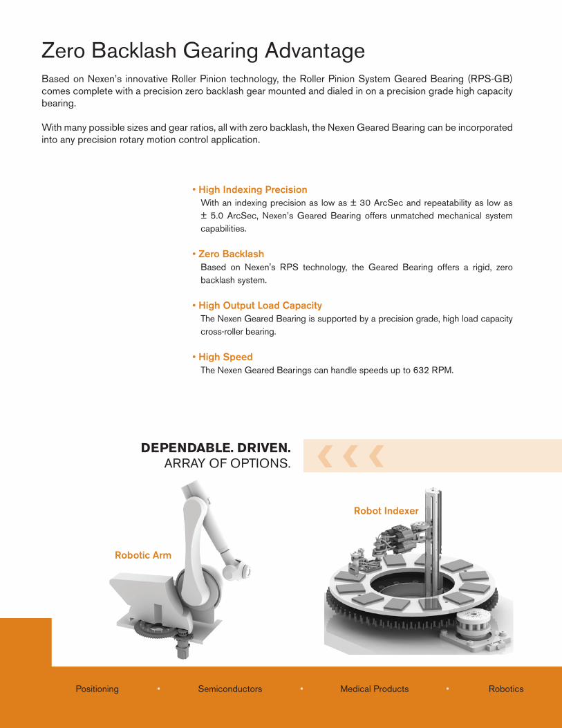
• High Indexing PrecisionWith an indexing precision as low as ± 30 ArcSec and repeatability as low as ± 5.0 ArcSec, Nexen’s Geared Bearing offers unmatched mechanical system capabilities.
• Zero BacklashBased on Nexen's RPS technology, the Geared Bearing offers a rigid, zero backlash system.
• High Output Load CapacityThe Nexen Geared Bearing is supported by a precision grade, high load capacity cross-roller bearing.
• High SpeedThe Nexen Geared Bearings can handle speeds up to 632 RPM.
Based on Nexen’s innovative Roller Pinion technology, the Roller Pinion System Geared Bearing (RPS-GB) comes complete with a precision zero backlash gear mounted and dialed in on a precision grade high capacity bearing.
With many possible sizes and gear ratios, all with zero backlash, the Nexen Geared Bearing can be incorporated into any precision rotary motion control application.
DEPENDABLE. DRIVEN.ARRAY OF OPTIONS.
Positioning • Semiconductors • Medical Products • Robotics
Zero Backlash Gearing Advantage
Robot Indexer
3
Head Stock/Tail StockPositioner
Positioning • Semiconductors • Medical Products • Robotics Material Fabrication • Automotive • Aerospace • Welding
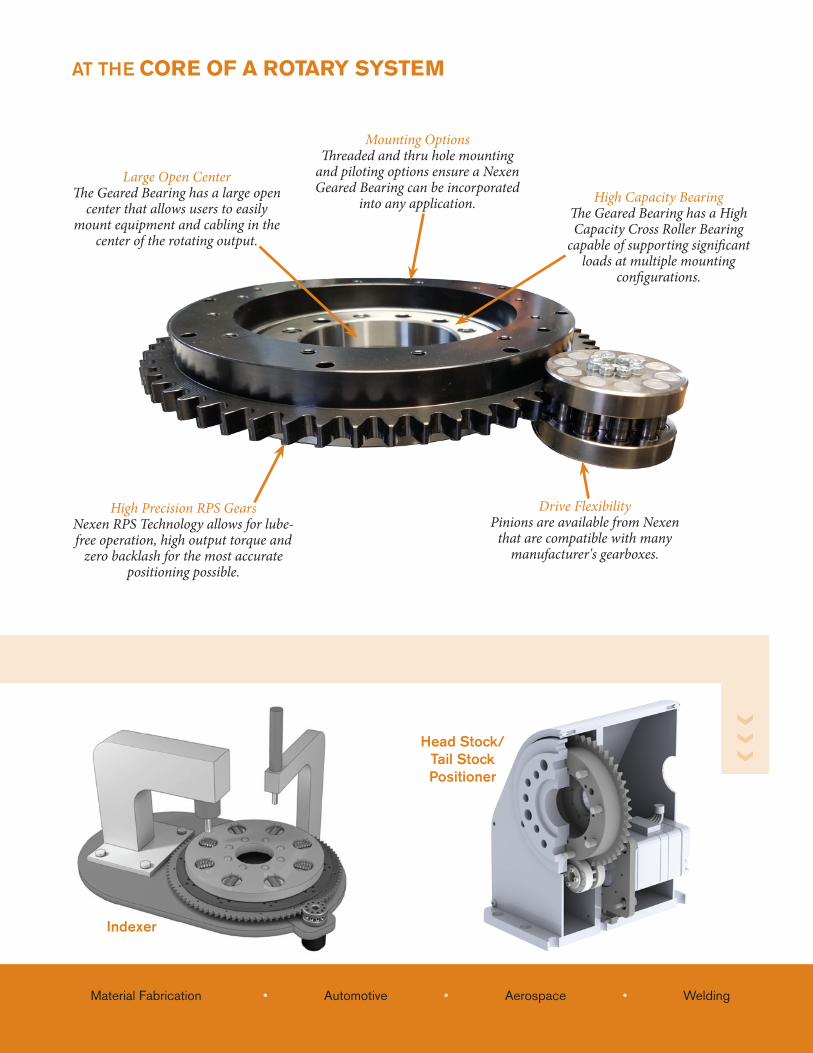
AT THE CORE OF A ROTARY SYSTEM
Drive FlexibilityPinions are available from Nexen
that are compatible with many manufacturer's gearboxes.
High Precision RPS GearsNexen RPS Technology allows for lube-free operation, high output torque and
zero backlash for the most accurate positioning possible.
Large Open Center The Geared Bearing has a large open
center that allows users to easily mount equipment and cabling in the
center of the rotating output.
High Capacity BearingThe Geared Bearing has a High Capacity Cross Roller Bearing
capable of supporting significant loads at multiple mounting
configurations.
Mounting OptionsThreaded and thru hole mounting
and piloting options ensure a Nexen Geared Bearing can be incorporated
into any application.
Indexer
4
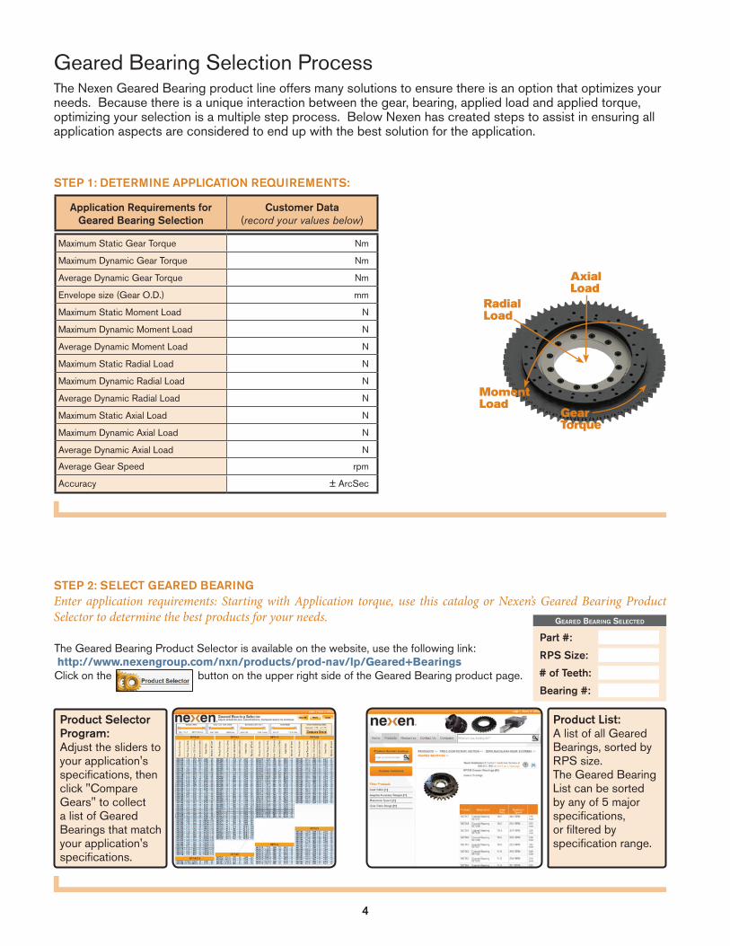
The Nexen Geared Bearing product line offers many solutions to ensure there is an option that optimizes your needs. Because there is a unique interaction between the gear, bearing, applied load and applied torque, optimizing your selection is a multiple step process. Below Nexen has created steps to assist in ensuring all application aspects are considered to end up with the best solution for the application.
Geared Bearing Selection Process
STEP 2: SELECT GEARED BEARINGEnter application requirements: Starting with Application torque, use this catalog or Nexen’s Geared Bearing Product Selector to determine the best products for your needs.
The Geared Bearing Product Selector is available on the website, use the following link: http://www.nexengroup.com/nxn/products/prod-nav/lp/Geared+BearingsClick on the button on the upper right side of the Geared Bearing product page.
Product Selector Program: Adjust the sliders to your application's specifications, then click "Compare Gears" to collect a list of Geared Bearings that match your application's specifications.
STEP 1: DETERMINE APPLICATION REQUIREMENTS:
Product List: A list of all Geared Bearings, sorted by RPS size. The Geared Bearing List can be sorted by any of 5 major specifications, or filtered by specification range.
Application Requirements for Geared Bearing Selection
Customer Data(record your values below)
Maximum Static Gear Torque Nm
Maximum Dynamic Gear Torque Nm
Average Dynamic Gear Torque Nm
Envelope size (Gear O.D.) mm
Maximum Static Moment Load N
Maximum Dynamic Moment Load N
Average Dynamic Moment Load N
Maximum Static Radial Load N
Maximum Dynamic Radial Load N
Average Dynamic Radial Load N
Maximum Static Axial Load N
Maximum Dynamic Axial Load N
Average Dynamic Axial Load N
Average Gear Speed rpm
Accuracy ± ArcSec
Geared BearinG Selected
Part #:
RPS Size:
# of Teeth:
AxialLoad
Radial Load
Gear Torque
Moment Load
Bearing #:
5
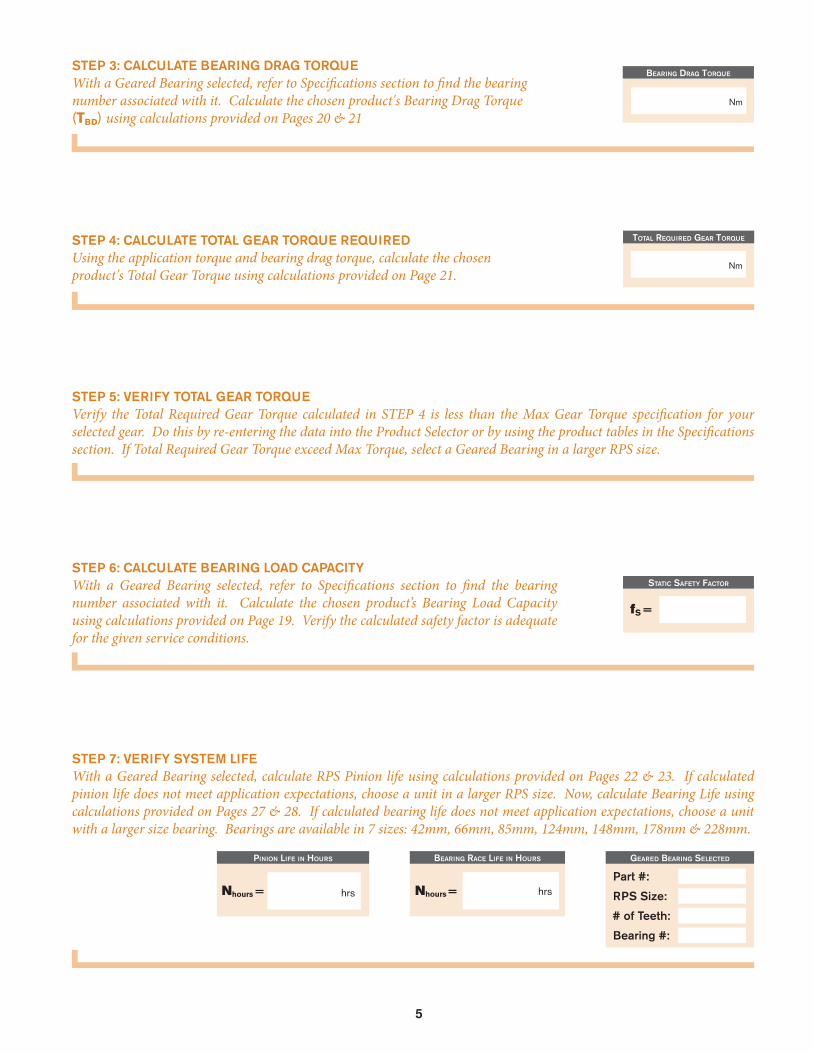
STEP 3: CALCULATE BEARING DRAG TORQUEWith a Geared Bearing selected, refer to Specifications section to find the bearing number associated with it. Calculate the chosen product's Bearing Drag Torque (TBD) using calculations provided on Pages 20 & 21
STEP 4: CALCULATE TOTAL GEAR TORQUE REQUIREDUsing the application torque and bearing drag torque, calculate the chosen product's Total Gear Torque using calculations provided on Page 21.
STEP 5: VERIFY TOTAL GEAR TORQUEVerify the Total Required Gear Torque calculated in STEP 4 is less than the Max Gear Torque specification for your selected gear. Do this by re-entering the data into the Product Selector or by using the product tables in the Specifications section. If Total Required Gear Torque exceed Max Torque, select a Geared Bearing in a larger RPS size.
STEP 6: CALCULATE BEARING LOAD CAPACITYWith a Geared Bearing selected, refer to Specifications section to find the bearing number associated with it. Calculate the chosen product’s Bearing Load Capacity using calculations provided on Page 19. Verify the calculated safety factor is adequate for the given service conditions.
STEP 7: VERIFY SYSTEM LIFEWith a Geared Bearing selected, calculate RPS Pinion life using calculations provided on Pages 22 & 23. If calculated pinion life does not meet application expectations, choose a unit in a larger RPS size. Now, calculate Bearing Life using calculations provided on Pages 27 & 28. If calculated bearing life does not meet application expectations, choose a unit with a larger size bearing. Bearings are available in 7 sizes: 42mm, 66mm, 85mm, 124mm, 148mm, 178mm & 228mm.
BearinG draG torque
total required Gear torque
Nm
Geared BearinG Selected
Part #:
RPS Size:
# of Teeth:
Bearing #:
Pinion life in HourS
hrsNhours =
BearinG race life in HourS
Nhours =
Nm
Static Safety factor
fS =
hrs
6
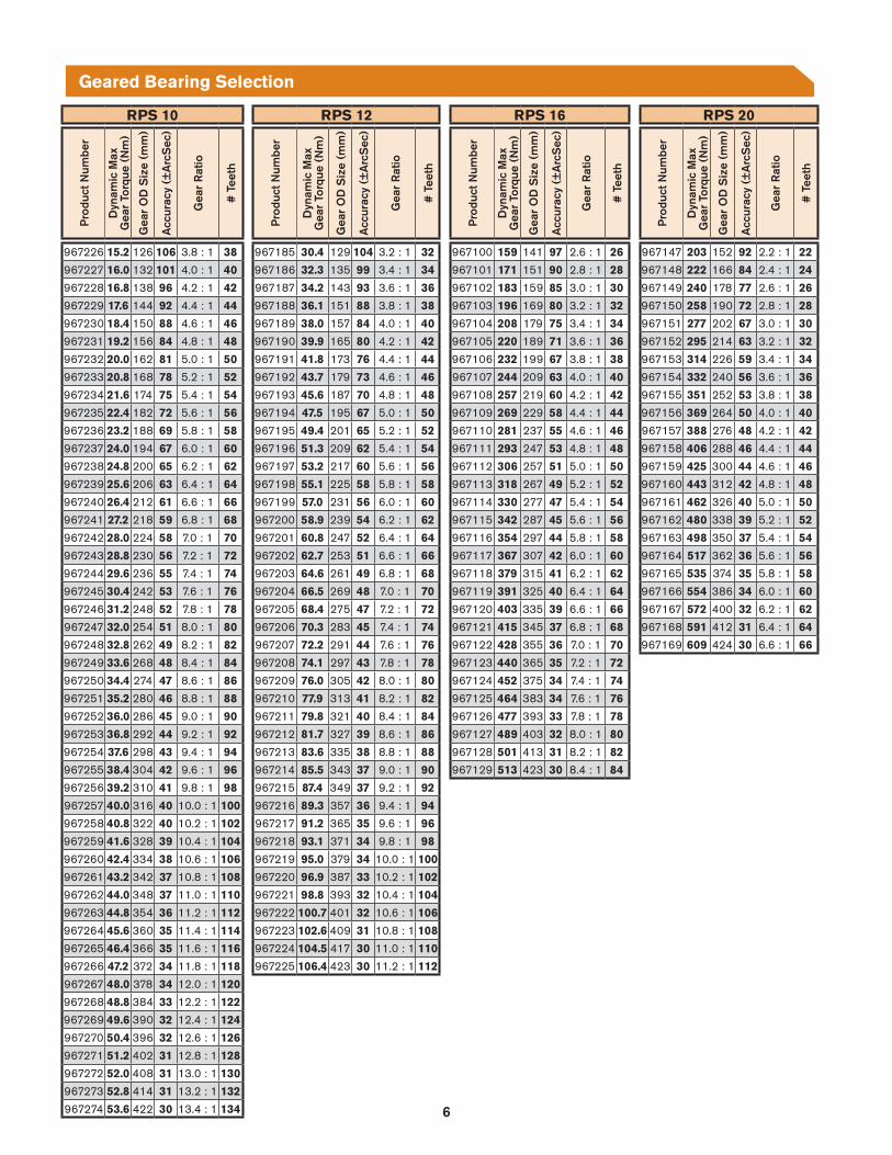
RPS 20
Pro
duct
Num
ber
Dyn
amic
Max
Gea
r To
rque
(N
m)
Gea
r O
D S
ize
(mm
)
Acc
urac
y (±
Arc
Sec
)
Gea
r R
atio
# T
eeth
967147 203 152 92 2.2 : 1 22
967148 222 166 84 2.4 : 1 24
967149 240 178 77 2.6 : 1 26
967150 258 190 72 2.8 : 1 28
967151 277 202 67 3.0 : 1 30
967152 295 214 63 3.2 : 1 32
967153 314 226 59 3.4 : 1 34
967154 332 240 56 3.6 : 1 36
967155 351 252 53 3.8 : 1 38
967156 369 264 50 4.0 : 1 40
967157 388 276 48 4.2 : 1 42
967158 406 288 46 4.4 : 1 44
967159 425 300 44 4.6 : 1 46
967160 443 312 42 4.8 : 1 48
967161 462 326 40 5.0 : 1 50
967162 480 338 39 5.2 : 1 52
967163 498 350 37 5.4 : 1 54
967164 517 362 36 5.6 : 1 56
967165 535 374 35 5.8 : 1 58
967166 554 386 34 6.0 : 1 60
967167 572 400 32 6.2 : 1 62
967168 591 412 31 6.4 : 1 64
967169 609 424 30 6.6 : 1 66
RPS 16
Pro
duct
Num
ber
Dyn
amic
Max
Gea
r To
rque
(N
m)
Gea
r O
D S
ize
(mm
)
Acc
urac
y (±
Arc
Sec
)
Gea
r R
atio
# T
eeth
967100 159 141 97 2.6 : 1 26
967101 171 151 90 2.8 : 1 28
967102 183 159 85 3.0 : 1 30
967103 196 169 80 3.2 : 1 32
967104 208 179 75 3.4 : 1 34
967105 220 189 71 3.6 : 1 36
967106 232 199 67 3.8 : 1 38
967107 244 209 63 4.0 : 1 40
967108 257 219 60 4.2 : 1 42
967109 269 229 58 4.4 : 1 44
967110 281 237 55 4.6 : 1 46
967111 293 247 53 4.8 : 1 48
967112 306 257 51 5.0 : 1 50
967113 318 267 49 5.2 : 1 52
967114 330 277 47 5.4 : 1 54
967115 342 287 45 5.6 : 1 56
967116 354 297 44 5.8 : 1 58
967117 367 307 42 6.0 : 1 60
967118 379 315 41 6.2 : 1 62
967119 391 325 40 6.4 : 1 64
967120 403 335 39 6.6 : 1 66
967121 415 345 37 6.8 : 1 68
967122 428 355 36 7.0 : 1 70
967123 440 365 35 7.2 : 1 72
967124 452 375 34 7.4 : 1 74
967125 464 383 34 7.6 : 1 76
967126 477 393 33 7.8 : 1 78
967127 489 403 32 8.0 : 1 80
967128 501 413 31 8.2 : 1 82
967129 513 423 30 8.4 : 1 84
RPS 12
Pro
duct
Num
ber
Dyn
amic
Max
Gea
r To
rque
(N
m)
Gea
r O
D S
ize
(mm
)
Acc
urac
y (±
Arc
Sec
)
Gea
r R
atio
# T
eeth
967185 30.4 129 104 3.2 : 1 32
967186 32.3 135 99 3.4 : 1 34
967187 34.2 143 93 3.6 : 1 36
967188 36.1 151 88 3.8 : 1 38
967189 38.0 157 84 4.0 : 1 40
967190 39.9 165 80 4.2 : 1 42
967191 41.8 173 76 4.4 : 1 44
967192 43.7 179 73 4.6 : 1 46
967193 45.6 187 70 4.8 : 1 48
967194 47.5 195 67 5.0 : 1 50
967195 49.4 201 65 5.2 : 1 52
967196 51.3 209 62 5.4 : 1 54
967197 53.2 217 60 5.6 : 1 56
967198 55.1 225 58 5.8 : 1 58
967199 57.0 231 56 6.0 : 1 60
967200 58.9 239 54 6.2 : 1 62
967201 60.8 247 52 6.4 : 1 64
967202 62.7 253 51 6.6 : 1 66
967203 64.6 261 49 6.8 : 1 68
967204 66.5 269 48 7.0 : 1 70
967205 68.4 275 47 7.2 : 1 72
967206 70.3 283 45 7.4 : 1 74
967207 72.2 291 44 7.6 : 1 76
967208 74.1 297 43 7.8 : 1 78
967209 76.0 305 42 8.0 : 1 80
967210 77.9 313 41 8.2 : 1 82
967211 79.8 321 40 8.4 : 1 84
967212 81.7 327 39 8.6 : 1 86
967213 83.6 335 38 8.8 : 1 88
967214 85.5 343 37 9.0 : 1 90
967215 87.4 349 37 9.2 : 1 92
967216 89.3 357 36 9.4 : 1 94
967217 91.2 365 35 9.6 : 1 96
967218 93.1 371 34 9.8 : 1 98
967219 95.0 379 34 10.0 : 1 100
967220 96.9 387 33 10.2 : 1 102
967221 98.8 393 32 10.4 : 1 104
967222 100.7 401 32 10.6 : 1 106
967223 102.6 409 31 10.8 : 1 108
967224 104.5 417 30 11.0 : 1 110
967225 106.4 423 30 11.2 : 1 112
RPS 10
Pro
duct
Num
ber
Dyn
amic
Max
Gea
r To
rque
(N
m)
Gea
r O
D S
ize
(mm
)
Acc
urac
y (±
Arc
Sec
)
Gea
r R
atio
# T
eeth
967226 15.2 126 106 3.8 : 1 38
967227 16.0 132 101 4.0 : 1 40
967228 16.8 138 96 4.2 : 1 42
967229 17.6 144 92 4.4 : 1 44
967230 18.4 150 88 4.6 : 1 46
967231 19.2 156 84 4.8 : 1 48
967232 20.0 162 81 5.0 : 1 50
967233 20.8 168 78 5.2 : 1 52
967234 21.6 174 75 5.4 : 1 54
967235 22.4 182 72 5.6 : 1 56
967236 23.2 188 69 5.8 : 1 58
967237 24.0 194 67 6.0 : 1 60
967238 24.8 200 65 6.2 : 1 62
967239 25.6 206 63 6.4 : 1 64
967240 26.4 212 61 6.6 : 1 66
967241 27.2 218 59 6.8 : 1 68
967242 28.0 224 58 7.0 : 1 70
967243 28.8 230 56 7.2 : 1 72
967244 29.6 236 55 7.4 : 1 74
967245 30.4 242 53 7.6 : 1 76
967246 31.2 248 52 7.8 : 1 78
967247 32.0 254 51 8.0 : 1 80
967248 32.8 262 49 8.2 : 1 82
967249 33.6 268 48 8.4 : 1 84
967250 34.4 274 47 8.6 : 1 86
967251 35.2 280 46 8.8 : 1 88
967252 36.0 286 45 9.0 : 1 90
967253 36.8 292 44 9.2 : 1 92
967254 37.6 298 43 9.4 : 1 94
967255 38.4 304 42 9.6 : 1 96
967256 39.2 310 41 9.8 : 1 98
967257 40.0 316 40 10.0 : 1 100
967258 40.8 322 40 10.2 : 1 102
967259 41.6 328 39 10.4 : 1 104
967260 42.4 334 38 10.6 : 1 106
967261 43.2 342 37 10.8 : 1 108
967262 44.0 348 37 11.0 : 1 110
967263 44.8 354 36 11.2 : 1 112
967264 45.6 360 35 11.4 : 1 114
967265 46.4 366 35 11.6 : 1 116
967266 47.2 372 34 11.8 : 1 118
967267 48.0 378 34 12.0 : 1 120
967268 48.8 384 33 12.2 : 1 122
967269 49.6 390 32 12.4 : 1 124
967270 50.4 396 32 12.6 : 1 126
967271 51.2 402 31 12.8 : 1 128
967272 52.0 408 31 13.0 : 1 130
967273 52.8 414 31 13.2 : 1 132
967274 53.6 422 30 13.4 : 1 134
Geared Bearing Selection
7
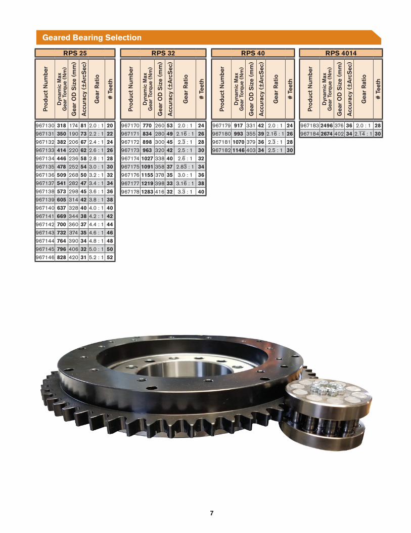
RPS 32
Pro
duct
Num
ber
Dyn
amic
Max
Gea
r To
rque
(N
m)
Gea
r O
D S
ize
(mm
)
Acc
urac
y (±
Arc
Sec
)
Gea
r R
atio
# T
eeth
967170 770 260 53 2.0 : 1 24
967171 834 280 49 2.16 : 1 26
967172 898 300 45 2.3 : 1 28
967173 963 320 42 2.5 : 1 30
967174 1027 338 40 2.6 : 1 32
967175 1091 358 37 2.83 : 1 34
967176 1155 378 35 3.0 : 1 36
967177 1219 398 33 3.16 : 1 38
967178 1283 416 32 3.3 : 1 40
RPS 40
Pro
duct
Num
ber
Dyn
amic
Max
Gea
r To
rque
(N
m)
Gea
r O
D S
ize
(mm
)
Acc
urac
y (±
Arc
Sec
)
Gea
r R
atio
# T
eeth
967179 917 331 42 2.0 : 1 24
967180 993 355 39 2.16 : 1 26
967181 1070 379 36 2.3 : 1 28
967182 1146 403 34 2.5 : 1 30
RPS 4014
Pro
duct
Num
ber
Dyn
amic
Max
Gea
r To
rque
(N
m)
Gea
r O
D S
ize
(mm
)
Acc
urac
y (±
Arc
Sec
)
Gea
r R
atio
# T
eeth
967183 2496 376 36 2.0 : 1 28
967184 2674 402 34 2.14 : 1 30
RPS 25P
rodu
ct N
umbe
r
Dyn
amic
Max
Gea
r To
rque
(N
m)
Gea
r O
D S
ize
(mm
)
Acc
urac
y (±
Arc
Sec
)
Gea
r R
atio
# T
eeth
967130 318 174 81 2.0 : 1 20
967131 350 190 73 2.2 : 1 22
967132 382 206 67 2.4 : 1 24
967133 414 220 62 2.6 : 1 26
967134 446 236 58 2.8 : 1 28
967135 478 252 54 3.0 : 1 30
967136 509 268 50 3.2 : 1 32
967137 541 282 47 3.4 : 1 34
967138 573 298 45 3.6 : 1 36
967139 605 314 42 3.8 : 1 38
967140 637 328 40 4.0 : 1 40
967141 669 344 38 4.2 : 1 42
967142 700 360 37 4.4 : 1 44
967143 732 374 35 4.6 : 1 46
967144 764 390 34 4.8 : 1 48
967145 796 406 32 5.0 : 1 50
967146 828 420 31 5.2 : 1 52
Geared Bearing Selection
8
RPS 10
General Specs Gear Torque Speed Precision Load InertiaP
rodu
ct N
umbe
r
Num
ber
of T
eeth
Gea
r R
atio
Bea
ring
Num
ber
Mod
ule
ofG
ear
Teet
h (m
m)
Sta
tic T
orqu
e (N
m)
Dyn
amic
Tor
que
atM
IN L
ife (
Nm
)D
ynam
ic T
orqu
e at
MA
X L
ife (
Nm
)
Max
Spe
ed (
RP
M)
Max
Lub
e-Fr
ee
Spe
ed (
RP
M)
Ang
ular
Acc
urac
y(±
Arc
Sec
)O
ne-W
ay
Rep
eata
bilit
y(±
Arc
Sec
)A
ngul
ar B
ackl
ash
(±A
rcS
ec)
Max
Dyn
amic
M
omen
t Loa
d @
M
ax L
ife &
A
vg T
orqu
e (k
Nm
)M
ax D
ynam
ic
Rad
ial L
oad@
M
ax L
ife &
A
vg T
orqu
e (k
N)
Max
Dyn
amic
A
xial
Loa
d @
M
ax L
ife &
A
vg T
orqu
e (k
N)
Mom
ent o
f Ine
rtia
OU
TER
(kg
/m2 )
Mom
ent o
f Ine
rtia
INN
ER
(kg
/m2 )
967226 38 3.8 : 1 42 2.1 23 15.2 15.2 632 82 106 17.6 0 0.0 2.3 3.6 .0026 .000019967227 40 4.0 : 1 42 2.1 24 16.0 16.0 600 78 101 16.8 0 0.0 2.3 3.6 .0028 .000019967228 42 4.2 : 1 42 2.1 26 16.8 16.8 571 74 96 16.0 0 0.0 2.3 3.6 .0030 .000019967229 44 4.4 : 1 42 2.1 27 17.6 17.6 545 71 92 15.3 0 0.0 2.3 3.6 .0033 .000019967230 46 4.6 : 1 66 2.1 28 18.4 18.4 522 68 88 14.6 0 0.2 6.0 9.1 .0058 .00015967231 48 4.8 : 1 66 2.1 29 19.2 19.2 500 65 84 14.0 0 0.2 6.0 9.1 .0062 .00015967232 50 5.0 : 1 66 2.1 30 20.0 20.0 480 62 81 13.5 0 0.2 6.0 9.1 .0065 .00015967233 52 5.2 : 1 66 2.1 32 20.8 20.8 462 60 78 13.0 0 0.2 6.0 9.1 .0070 .00015967234 54 5.4 : 1 85 2.1 33 21.6 21.6 444 58 75 12.5 0 0.3 7.0 10.6 .012 .00039967235 56 5.6 : 1 85 2.1 34 22.4 22.4 429 55 72 11.9 0 0.3 7.0 10.6 .012 .00039967236 58 5.8 : 1 85 2.1 35 23.2 23.2 414 53 69 11.5 0 0.3 7.0 10.6 .013 .00039967237 60 6.0 : 1 85 2.1 36 24.0 24.0 400 52 67 11.1 0 0.3 7.0 10.6 .014 .00039967238 62 6.2 : 1 85 2.1 38 24.8 24.8 387 50 65 10.8 0 0.3 7.0 10.6 .014 .00039967239 64 6.4 : 1 85 2.1 39 25.6 25.6 375 48 63 10.5 0 0.3 7.0 10.6 .015 .00039967240 66 6.6 : 1 85 2.1 40 26.4 26.4 364 47 61 10.2 0 0.3 7.0 10.6 .016 .00039967241 68 6.8 : 1 124 2.1 41 27.2 27.2 353 46 59 9.9 0 0.7 11.6 17.5 .032 .0028967242 70 7.0 : 1 124 2.1 43 28.0 28.0 343 44 58 9.6 0 0.7 11.6 17.5 .033 .0028967243 72 7.2 : 1 124 2.1 44 28.8 28.8 333 43 56 9.3 0 0.7 11.6 17.5 .034 .0028967244 74 7.4 : 1 124 2.1 45 29.6 29.6 324 42 55 9.1 0 0.7 11.6 17.5 .035 .0028967245 76 7.6 : 1 124 2.1 46 30.4 30.4 316 41 53 8.9 0 0.7 11.6 17.5 .037 .0028967246 78 7.8 : 1 124 2.1 47 31.2 31.2 308 40 52 8.6 0 0.7 11.6 17.5 .038 .0028967247 80 8.0 : 1 124 2.1 49 32.0 32.0 300 39 51 8.4 0 0.7 11.6 17.5 .040 .0028967248 82 8.2 : 1 124 2.1 50 32.8 32.8 293 38 49 8.2 0 0.7 11.6 17.5 .042 .0028967249 84 8.4 : 1 148 2.1 51 33.6 33.6 286 37 48 8.0 0 1.3 17.4 26.1 .080 .0063967250 86 8.6 : 1 148 2.1 52 34.4 34.4 279 36 47 7.8 0 1.3 17.4 26.1 .082 .0063967251 88 8.8 : 1 148 2.1 54 35.2 35.2 273 35 46 7.6 0 1.3 17.4 26.1 .084 .0063967252 90 9.0 : 1 148 2.1 55 36.0 36.0 267 34 45 7.4 0 1.3 17.4 26.1 .086 .0063967253 92 9.2 : 1 148 2.1 56 36.8 36.8 261 34 44 7.3 0 1.3 17.4 26.1 .089 .0063967254 94 9.4 : 1 178 2.1 57 37.6 37.6 255 33 43 7.1 0 2.5 28.6 42.9 .12 .015967255 96 9.6 : 1 178 2.1 58 38.4 38.4 250 32 42 7.0 0 2.5 28.6 42.9 .13 .015967256 98 9.8 : 1 178 2.1 60 39.2 39.2 245 32 41 6.9 0 2.5 28.6 42.9 .13 .015967257 100 10.0 : 1 178 2.1 61 40.0 40.0 240 31 40 6.7 0 2.5 28.6 42.9 .13 .015967258 102 10.2 : 1 178 2.1 62 40.8 40.8 235 31 40 6.6 0 2.5 28.6 42.9 .13 .015967259 104 10.4 : 1 178 2.1 63 41.6 41.6 231 30 39 6.5 0 2.5 28.6 42.9 .14 .015967260 106 10.6 : 1 178 2.1 64 42.4 42.4 226 29 38 6.3 0 2.5 28.6 42.9 .14 .015967261 108 10.8 : 1 178 2.1 66 43.2 43.2 222 29 37 6.2 0 2.5 28.6 42.9 .15 .015967262 110 11.0 : 1 228 2.1 67 44.0 44.0 218 28 37 6.1 0 4.2 37.2 55.6 .25 .044967263 112 11.2 : 1 228 2.1 68 44.8 44.8 214 28 36 6.0 0 4.2 37.2 55.6 .25 .044967264 114 11.4 : 1 228 2.1 69 45.6 45.6 211 27 35 5.9 0 4.2 37.2 55.6 .26 .044967265 116 11.6 : 1 228 2.1 71 46.4 46.4 207 27 35 5.8 0 4.2 37.2 55.6 .26 .044967266 118 11.8 : 1 228 2.1 72 47.2 47.2 203 26 34 5.7 0 4.2 37.2 55.6 .27 .044967267 120 12.0 : 1 228 2.1 73 48.0 48.0 200 26 34 5.6 0 4.2 37.2 55.6 .27 .044967268 122 12.2 : 1 228 2.1 74 48.8 48.8 197 25 33 5.5 0 4.2 37.2 55.6 .28 .044967269 124 12.4 : 1 228 2.1 75 49.6 49.6 194 25 32 5.4 0 4.2 37.2 55.6 .28 .044967270 126 12.6 : 1 228 2.1 77 50.4 50.4 190 25 32 5.3 0 4.2 37.2 55.6 .29 .044967271 128 12.8 : 1 228 2.1 78 51.2 51.2 188 24 31 5.2 0 4.2 37.2 55.6 .29 .044967272 130 13.0 : 1 228 2.1 79 52.0 52.0 185 24 31 5.2 0 4.2 37.2 55.6 .30 .044967273 132 13.2 : 1 228 2.1 80 52.8 52.8 182 24 31 5.1 0 4.2 37.2 55.6 .31 .044967274 134 13.4 : 1 228 2.1 81 53.6 53.6 179 23 30 5.0 0 4.2 37.2 55.6 .32 .044
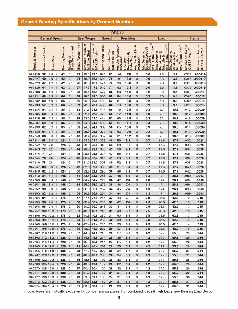
Geared Bearing Specifications by Product Number
(1)
(1)
(1)
(1) Load types are mutually exclusive for comparison purposes. For combined loads & high loads, see Bearing Load Section.

9
RPS 10
Part ID. Dimensions System Reaction Forces (Under Max. Torque Condition)
Pro
duct
Num
ber
Num
ber
of T
eeth
Gea
r To
oth
O.D
. Siz
e (m
m)
Out
put H
ole
Bol
t Circ
le Ø
(m
m)
Out
put P
ilot I
.D.
(mm
)M
ount
ing
Hol
eB
olt C
ircle
Ø (
mm
)M
ount
ing
Pilo
t I.D
.(m
m)
Pin
ion
Cen
ter
Dis
tanc
e (m
m)
Ove
rall
Hei
ght
(mm
)
Wei
ght/
Mas
s (k
g)
Ave
rage
S
epar
atio
n (N
)
Max
Sep
arat
ion
(N)
Ave
rage
Tor
que
Indu
ced
Rad
ial (
N)
Max
Tor
que
Indu
ced
Rad
ial (
N)
967226 38 126 60 50 28 20 74 38 1.7 79 113 271 283967227 40 132 60 50 28 20 77 38 1.8 79 113 271 283967228 42 138 60 50 28 20 80 38 1.8 78 113 271 283967229 44 144 60 50 28 20 83 38 1.9 77 113 272 284967230 46 150 85 75 45 35 86 39.5 2.5 77 113 272 284967231 48 156 85 75 45 35 89 39.5 2.5 77 113 272 284967232 50 162 85 75 45 35 92 39.5 2.6 76 113 272 284967233 52 168 85 75 45 35 95 39.5 2.7 76 113 272 284967234 54 174 107.5 95 65 55 98 39.5 3.4 75 113 272 285967235 56 182 107.5 95 65 55 102 39.5 3.5 82 116 271 284967236 58 188 107.5 95 65 55 105 39.5 3.5 81 116 272 284967237 60 194 107.5 95 65 55 108 39.5 3.6 81 116 272 284967238 62 200 107.5 95 65 55 111 39.5 3.7 81 116 272 284967239 64 206 107.5 95 65 55 114 39.5 3.8 80 116 272 284967240 66 212 107.5 95 65 55 117 39.5 3.9 80 116 272 284967241 68 218 150 135 97 80 120 44 5.9 79 116 272 285967242 70 224 150 135 97 80 123 44 6.0 79 116 272 285967243 72 230 150 135 97 80 126 44 6.1 79 115 272 285967244 74 236 150 135 97 80 129 44 6.2 78 115 272 285967245 76 242 150 135 97 80 132 44 6.3 78 115 272 285967246 78 248 150 135 97 80 135 44 6.4 78 115 272 285967247 80 254 150 135 97 80 138 44 6.5 78 115 272 285967248 82 262 150 135 97 80 142 44 6.6 82 117 272 284967249 84 268 195 165 112 90 145 45.5 9.8 82 117 272 285967250 86 274 195 165 112 90 148 45.5 9.9 81 117 272 285967251 88 280 195 165 112 90 151 45.5 10.0 81 117 272 285967252 90 286 195 165 112 90 154 45.5 10.0 81 117 272 285967253 92 292 195 165 112 90 157 45.5 10.0 80 117 272 285967254 94 298 220 195 139 115 160 47 12.0 80 117 272 285967255 96 304 220 195 139 115 163 47 12.0 80 117 272 285967256 98 310 220 195 139 115 166 47 13.0 80 117 272 285967257 100 316 220 195 139 115 169 47 13.0 79 117 272 285967258 102 322 220 195 139 115 172 47 13.0 79 117 272 285967259 104 328 220 195 139 115 175 47 13.0 79 117 272 285967260 106 334 220 195 139 115 178 47 13.0 79 116 272 286967261 108 342 220 195 139 115 182 47 13.0 82 118 272 285967262 110 348 275 250 184 160 185 51 18.0 82 118 272 285967263 112 354 275 250 184 160 188 51 18.0 81 118 272 285967264 114 360 275 250 184 160 191 51 18.0 81 118 272 285967265 116 366 275 250 184 160 194 51 18.0 81 118 272 285967266 118 372 275 250 184 160 197 51 19.0 81 118 272 285967267 120 378 275 250 184 160 200 51 19.0 81 118 272 285967268 122 384 275 250 184 160 203 51 19.0 80 118 272 285967269 124 390 275 250 184 160 206 51 19.0 80 118 272 285967270 126 396 275 250 184 160 209 51 19.0 80 117 272 286967271 128 402 275 250 184 160 212 51 19.0 80 117 272 286967272 130 408 275 250 184 160 215 51 19.0 80 117 272 286967273 132 414 275 250 184 160 218 51 20.0 79 117 272 286967274 134 422 275 250 184 160 222 51 20.0 82 119 272 285
MOUNTING HOLEBOLT CIRCLE⌀
GEARTOOTHO.D. SIZE
OUTPUT HOLEBOLT CIRCLE⌀
PINIONCENTER
DISTANCE
OUTPUT PILOT I.D.
10 mm
MOUNTINGPILOT I.D.
OVERALLHEIGHT
SECTION A-A
A A
GREASEFITTINGS2 AT 180°
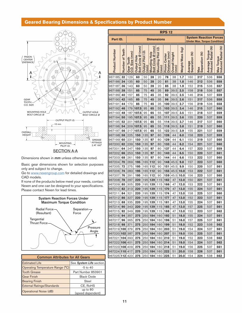
Geared Bearing Dimensions & Specifications by Product Number
Basic gear dimensions shown for selection purposes only and subject to change. Go to www.nexengroup.com for detailed drawings and CAD models. If none of the products below meet your needs, contact Nexen and one can be designed to your specifications. Please contact Nexen for lead times.
Dimensions shown in mm unless otherwise noted.
Common Attributes for All Gears
Estimated Life See System Life section.Operating Temperature Range (°C) -5 to 40Tooth Grease Part Number 853901Gear Finish Black OxideBearing Finish SteelExternal Ratings/Standards CE, RoHS
Operational Noise (dB) up to 80 (speed dependent)
SeparationForce
PressureAngle
Radial Force(Resultant)
TangentialThrust Force
System Reaction Forces Under Maximum Torque Condition

10
RPS 12
General Specs Gear Torque Speed Precision Load Inertia
Pro
duct
Num
ber
Num
ber
of T
eeth
Gea
r R
atio
Bea
ring
Num
ber
Mod
ule
ofG
ear
Teet
h (m
m)
Sta
tic T
orqu
e (N
m)
Dyn
amic
Tor
que
atM
IN L
ife (
Nm
)
Dyn
amic
Tor
que
atM
AX
Life
(N
m)
Max
Spe
ed (
RP
M)
Max
Lub
e-Fr
ee
Spe
ed (
RP
M)
Ang
ular
Acc
urac
y(±
Arc
Sec
)O
ne-W
ay
Rep
eata
bilit
y(±
Arc
Sec
)A
ngul
ar B
ackl
ash
(±A
rcS
ec)
Max
Dyn
amic
M
omen
t Loa
d @
M
ax L
ife &
A
vg T
orqu
e (k
Nm
)M
ax D
ynam
ic
Rad
ial L
oad@
M
ax L
ife &
A
vg T
orqu
e (k
N)
Max
Dyn
amic
A
xial
Loa
d @
M
ax L
ife &
A
vg T
orqu
e (k
N)
Mom
ent o
f Ine
rtia
OU
TER
(kg
/m2 )
Mom
ent o
f Ine
rtia
INN
ER
(kg
/m2 )
967185 32 3.2 : 1 42 2.4 46 30.4 30.4 625 80 104 17.3 0 0.0 1.9 3.2 .003 .00002967186 34 3.4 : 1 42 2.4 48 32.3 32.3 588 76 99 16.5 0 0.0 1.9 3.2 .003 .00002967187 36 3.6 : 1 42 2.4 51 34.2 34.2 556 72 93 15.5 0 0.0 1.9 3.2 .003 .00002967188 38 3.8 : 1 66 2.4 54 36.1 36.1 526 68 88 14.6 0 0.2 5.6 8.7 .006 .00015967189 40 4.0 : 1 66 2.4 57 38.0 38.0 500 65 84 14.0 0 0.2 5.6 8.7 .006 .00015967190 42 4.2 : 1 66 2.4 60 39.9 39.9 476 62 80 13.3 0 0.2 5.6 8.7 .007 .00015967191 44 4.4 : 1 66 2.4 63 41.8 41.8 455 59 76 12.7 0 0.2 5.6 8.7 .007 .00015967192 46 4.6 : 1 85 2.4 66 43.7 43.7 435 57 73 12.2 0 0.3 6.7 10.3 .012 .0004967193 48 4.8 : 1 85 2.4 68 45.6 45.6 417 54 70 11.7 0 0.3 6.7 10.3 .013 .0004967194 50 5.0 : 1 85 2.4 71 47.5 47.5 400 52 67 11.1 0 0.3 6.7 10.3 .014 .0004967195 52 5.2 : 1 85 2.4 74 49.4 49.4 385 50 65 10.8 0 0.3 6.7 10.3 .014 .0004967196 54 5.4 : 1 85 2.4 77 51.3 51.3 370 48 62 10.4 0 0.3 6.7 10.3 .015 .0004967197 56 5.6 : 1 85 2.4 80 53.2 53.2 357 46 60 10.0 0 0.3 6.7 10.3 .017 .0004967198 58 5.8 : 1 124 2.4 83 55.1 55.1 345 44 58 9.6 0 0.7 11.3 17.2 .033 .0028967199 60 6.0 : 1 124 2.4 86 57.0 57.0 333 43 56 9.3 0 0.7 11.3 17.2 .034 .0028967200 62 6.2 : 1 124 2.4 88 58.9 58.9 323 42 54 9.0 0 0.7 11.3 17.2 .036 .0028967201 64 6.4 : 1 124 2.4 91 60.8 60.8 313 40 52 8.7 0 0.7 11.3 17.2 .038 .0028967202 66 6.6 : 1 124 2.4 94 62.7 62.7 303 39 51 8.5 0 0.7 11.3 17.2 .039 .0028967203 68 6.8 : 1 124 2.4 97 64.6 64.6 294 38 49 8.2 0 0.7 11.3 17.2 .041 .0028967204 70 7.0 : 1 148 2.4 100 66.5 66.5 286 37 48 8.0 0 1.3 17.1 25.8 .080 .0063
967205 72 7.2 : 1 148 2.4 103 68.4 68.4 278 36 47 7.8 0 1.3 17.1 25.8 .082 .0063
967206 74 7.4 : 1 148 2.4 105 70.3 70.3 270 35 45 7.6 0 1.3 17.1 25.8 .085 .0063967207 76 7.6 : 1 148 2.4 108 72.2 72.2 263 34 44 7.3 0 1.3 17.1 25.8 .088 .0063967208 78 7.8 : 1 178 2.4 111 74.1 74.1 256 33 43 7.2 0 2.5 28.3 42.6 .12 .015967209 80 8.0 : 1 178 2.4 114 76.0 76.0 250 32 42 7.0 0 2.5 28.3 42.6 .13 .015967210 82 8.2 : 1 178 2.4 117 77.9 77.9 244 32 41 6.8 0 2.5 28.3 42.6 .13 .015967211 84 8.4 : 1 178 2.4 120 79.8 79.8 238 31 40 6.6 0 2.5 28.3 42.6 .13 .015967212 86 8.6 : 1 178 2.4 123 81.7 81.7 233 30 39 6.5 0 2.5 28.3 42.6 .14 .015967213 88 8.8 : 1 178 2.4 125 83.6 83.6 227 29 38 6.3 0 2.5 28.3 42.6 .14 .015967214 90 9.0 : 1 178 2.4 128 85.5 85.5 222 29 37 6.2 0 2.5 28.3 42.6 .15 .015967215 92 9.2 : 1 178 2.4 131 87.4 87.4 217 28 37 6.1 0 2.5 28.3 42.6 .15 .015967216 94 9.4 : 1 228 2.4 134 89.3 89.3 213 28 36 5.9 0 4.2 36.9 55.3 .25 .044967217 96 9.6 : 1 228 2.4 137 91.2 91.2 208 27 35 5.8 0 4.2 36.9 55.3 .26 .044967218 98 9.8 : 1 228 2.4 140 93.1 93.1 204 26 34 5.7 0 4.2 36.9 55.3 .26 .044967219 100 10.0 : 1 228 2.4 143 95.0 95.0 200 26 34 5.6 0 4.2 36.9 55.3 .27 .044967220 102 10.2 : 1 228 2.4 145 96.9 96.9 196 25 33 5.5 0 4.2 36.9 55.3 .28 .044967221 104 10.4 : 1 228 2.4 148 98.8 98.8 192 25 32 5.4 0 4.2 36.9 55.3 .28 .044967222 106 10.6 : 1 228 2.4 151 100.7 100.7 189 24 32 5.3 0 4.2 36.9 55.3 .29 .044967223 108 10.8 : 1 228 2.4 154 102.6 102.6 185 24 31 5.2 0 4.2 36.9 55.3 .30 .044967224 110 11.0 : 1 228 2.4 157 104.5 104.5 182 23 30 5.1 0 4.2 36.9 55.3 .31 .044967225 112 11.2 : 1 228 2.4 160 106.4 106.4 179 23 30 5.0 0 4.2 36.9 55.3 .32 .044
Geared Bearing Specifications by Product Number
(1)
(1)
(1)
(1) Load types are mutually exclusive for comparison purposes. For combined loads & high loads, see Bearing Load Section.
11
RPS 12
Part ID. Dimensions System Reaction Forces (Under Max. Torque Condition)
Pro
duct
Num
ber
Num
ber
of T
eeth
Gea
r To
oth
O.D
. Siz
e (m
m)
Out
put H
ole
Bol
t Circ
le Ø
(m
m)
Out
put P
ilot I
.D.
(mm
)M
ount
ing
Hol
eB
olt C
ircle
Ø (
mm
)M
ount
ing
Pilo
t I.D
.(m
m)
Pin
ion
Cen
ter
Dis
tanc
e (m
m)
Ove
rall
Hei
ght
(mm
)
Wei
ght/
Mas
s (k
g)
Ave
rage
S
epar
atio
n (N
)
Max
Sep
arat
ion
(N)
Ave
rage
Tor
que
Indu
ced
Rad
ial (
N)
Max
Tor
que
Indu
ced
Rad
ial (
N)
967185 32 129 60 50 28 20 78 38 1.7 160 217 536 556967186 34 135 60 50 28 20 81 38 1.8 146 212 536 558967187 36 143 60 50 28 20 85 38 1.9 152 215 536 557967188 38 151 85 75 45 35 89 39.5 2.5 158 218 536 557967189 40 157 85 75 45 35 92 39.5 2.5 146 214 537 559967190 42 165 85 75 45 35 96 39.5 2.6 151 217 536 558967191 44 173 85 75 45 35 100 39.5 2.7 156 219 536 558967192 46 179 107.5 95 65 55 103 39.5 3.4 146 215 537 560967193 48 187 107.5 95 65 55 107 39.5 3.5 151 218 537 559967194 50 195 107.5 95 65 55 111 39.5 3.6 155 220 537 559967195 52 201 107.5 95 65 55 114 39.5 3.7 146 217 537 560967196 54 209 107.5 95 65 55 118 39.5 3.8 151 219 537 560967197 56 217 107.5 95 65 55 122 39.5 3.9 155 221 537 559967198 58 225 150 135 97 80 126 44 6.0 158 223 537 559967199 60 231 150 135 97 80 129 44 6.1 150 219 537 560967200 62 239 150 135 97 80 133 44 6.2 154 221 537 560967201 64 247 150 135 97 80 137 44 6.4 157 223 537 559967202 66 253 150 135 97 80 140 44 6.5 150 220 537 561967203 68 261 150 135 97 80 144 44 6.6 153 222 537 560967204 70 269 195 165 112 90 148 45.5 9.8 157 223 537 560967205 72 275 195 165 112 90 151 45.5 9.9 150 220 537 561967206 74 283 195 165 112 90 155 45.5 10.0 153 222 537 561967207 76 291 195 165 112 90 159 45.5 10.0 156 223 537 560967208 78 297 220 195 139 115 162 47 12.0 150 221 537 561967209 80 305 220 195 139 115 166 47 12.0 153 222 537 561967210 82 313 220 195 139 115 170 47 13.0 155 224 537 561967211 84 321 220 195 139 115 174 47 13.0 158 225 537 560967212 86 327 220 195 139 115 177 47 13.0 152 223 537 561967213 88 335 220 195 139 115 181 47 13.0 155 224 537 561967214 90 343 220 195 139 115 185 47 13.0 157 225 537 561967215 92 349 220 195 139 115 188 47 13.0 152 223 537 562967216 94 357 275 250 184 160 192 51 18.0 155 224 537 561967217 96 365 275 250 184 160 196 51 18.0 157 225 537 561967218 98 371 275 250 184 160 199 51 18.0 152 223 538 562967219 100 379 275 250 184 160 203 51 19.0 154 224 537 561967220 102 387 275 250 184 160 207 51 19.0 156 225 537 561967221 104 393 275 250 184 160 210 51 19.0 152 223 538 562967222 106 401 275 250 184 160 214 51 19.0 154 224 537 562967223 108 409 275 250 184 160 218 51 19.0 156 225 537 561967224 110 417 275 250 184 160 222 51 20.0 158 226 537 561967225 112 423 275 250 184 160 225 51 20.0 154 224 538 562
Geared Bearing Dimensions & Specifications by Product Number
MOUNTING HOLEBOLT CIRCLE⌀
GEARTOOTHO.D. SIZE
OUTPUT HOLEBOLT CIRCLE⌀
PINIONCENTER
DISTANCE
OUTPUT PILOT I.D.
10 mm
MOUNTINGPILOT I.D.
OVERALLHEIGHT
SECTION A-A
A A
GREASEFITTINGS2 AT 180°
Basic gear dimensions shown for selection purposes only and subject to change. Go to www.nexengroup.com for detailed drawings and CAD models. If none of the products below meet your needs, contact Nexen and one can be designed to your specifications. Please contact Nexen for lead times.
Dimensions shown in mm unless otherwise noted.
Common Attributes for All Gears
Estimated Life See System Life section.Operating Temperature Range (°C) -5 to 40Tooth Grease Part Number 853901Gear Finish Black OxideBearing Finish SteelExternal Ratings/Standards CE, RoHS
Operational Noise (dB) up to 80 (speed dependent)
SeparationForce
PressureAngle
Radial Force(Resultant)
TangentialThrust Force
System Reaction Forces Under Maximum Torque Condition

12
RPS 16
General Specs Gear Torque Speed Precision Load InertiaP
rodu
ct N
umbe
r
Num
ber
of T
eeth
Gea
r R
atio
Bea
ring
Num
ber
Mod
ule
ofG
ear
Teet
h (m
m)
Sta
tic T
orqu
e (N
m)
Dyn
amic
Tor
que
atM
IN L
ife (
Nm
)D
ynam
ic T
orqu
e at
MA
X L
ife (
Nm
)
Max
Spe
ed (
RP
M)
Max
Lub
e-Fr
ee
Spe
ed (
RP
M)
Ang
ular
Acc
urac
y(±
Arc
Sec
)O
ne-W
ay
Rep
eata
bilit
y(±
Arc
Sec
)A
ngul
ar B
ackl
ash
(±A
rcS
ec)
Max
Dyn
amic
M
omen
t Loa
d @
M
ax L
ife &
A
vg T
orqu
e (k
Nm
)M
ax D
ynam
ic
Rad
ial L
oad@
M
ax L
ife &
A
vg T
orqu
e (k
N)
Max
Dyn
amic
A
xial
Loa
d @
M
ax L
ife &
A
vg T
orqu
e (k
N)
Mom
ent o
f Ine
rtia
OU
TER
(kg
/m2 )
Mom
ent o
f Ine
rtia
INN
ER
(kg
/m2 )
967100 26 2.6 : 1 42 3.4 159 159 88 577 75 97 16.2 0 0.0 0.4 1.0 .004 .00002967101 28 2.8 : 1 42 3.4 171 171 94 536 70 90 15.1 0 0.0 0.4 1.0 .005 .00002967102 30 3.0 : 1 42 3.4 183 183 101 500 66 85 14.2 0 0.0 0.4 1.0 .006 .00002967103 32 3.2 : 1 66 3.4 196 196 108 469 62 80 13.3 0 0.1 4.4 7.5 .009 .00015967104 34 3.4 : 1 66 3.4 208 208 115 441 58 75 12.5 0 0.1 4.4 7.5 .011 .00015967105 36 3.6 : 1 85 3.4 220 220 121 417 55 71 11.8 0 0.2 5.5 9.1 .016 .00039967106 38 3.8 : 1 85 3.4 232 232 128 395 52 67 11.1 0 0.2 5.5 9.1 .018 .00039967107 40 4.0 : 1 85 3.4 244 244 135 375 49 63 10.6 0 0.2 5.5 9.1 .021 .00039967108 42 4.2 : 1 85 3.4 257 257 142 357 47 60 10.1 0 0.2 5.5 9.1 .024 .00039967109 44 4.4 : 1 85 3.4 269 269 148 341 44 58 9.6 0 0.2 5.5 9.1 .027 .00040967110 46 4.6 : 1 124 3.4 281 281 155 326 43 55 9.2 0 0.6 10.2 16.0 .043 .0028967111 48 4.8 : 1 124 3.4 293 293 162 313 41 53 8.9 0 0.6 10.2 16.0 .047 .0028967112 50 5.0 : 1 124 3.4 306 306 169 300 39 51 8.5 0 0.6 10.2 16.0 .052 .0028967113 52 5.2 : 1 124 3.4 318 318 175 288 38 49 8.2 0 0.6 10.2 16.0 .058 .0028967114 54 5.4 : 1 148 3.4 330 330 182 278 36 47 7.8 0 1.2 16.0 24.7 .095 .0063967115 56 5.6 : 1 148 3.4 342 342 189 268 35 45 7.6 0 1.2 16.0 24.7 .10 .0063967116 58 5.8 : 1 148 3.4 354 354 195 259 34 44 7.3 0 1.2 16.0 24.7 .11 .0063967117 60 6.0 : 1 178 3.4 367 367 202 250 33 42 7.0 0 2.4 27.3 41.5 .15 .015967118 62 6.2 : 1 178 3.4 379 379 209 242 32 41 6.9 0 2.4 27.3 41.5 .15 .015967119 64 6.4 : 1 178 3.4 391 391 216 234 31 40 6.6 0 2.4 27.3 41.5 .16 .015967120 66 6.6 : 1 178 3.4 403 403 222 227 30 39 6.4 0 2.4 27.3 41.5 .17 .015967121 68 6.8 : 1 178 3.4 415 415 229 221 29 37 6.2 0 2.4 27.3 41.5 .19 .015967122 70 7.0 : 1 178 3.4 428 428 236 214 28 36 6.0 0 2.4 27.3 41.5 .20 .015967123 72 7.2 : 1 228 3.4 440 440 243 208 27 35 5.9 0 4.1 35.8 54.3 .29 .044967124 74 7.4 : 1 228 3.4 452 452 249 203 26 34 5.7 0 4.1 35.8 54.3 .31 .044967125 76 7.6 : 1 228 3.4 464 464 256 197 26 34 5.6 0 4.1 35.8 54.3 .32 .044967126 78 7.8 : 1 228 3.4 477 477 263 192 25 33 5.4 0 4.1 35.8 54.3 .34 .044967127 80 8.0 : 1 228 3.4 489 489 270 188 25 32 5.3 0 4.1 35.8 54.3 .36 .044967128 82 8.2 : 1 228 3.4 501 501 276 183 24 31 5.2 0 4.1 35.8 54.3 .39 .044967129 84 8.4 : 1 228 3.4 513 513 283 179 23 30 5.0 0 4.1 35.8 54.3 .41 .044
Geared Bearing Specifications by Product Number
(1)
(1)
(1)
(1) Load types are mutually exclusive for comparison purposes. For combined loads & high loads, see Bearing Load Section.

13
RPS 16
Part ID. Dimensions System Reaction Forces (Under Max. Torque Condition)
Pro
duct
Num
ber
Num
ber
of T
eeth
Gea
r To
oth
O.D
. Siz
e (m
m)
Out
put H
ole
Bol
t Circ
le Ø
(m
m)
Out
put P
ilot I
.D.
(mm
)M
ount
ing
Hol
eB
olt C
ircle
Ø (
mm
)M
ount
ing
Pilo
t I.D
.(m
m)
Pin
ion
Cen
ter
Dis
tanc
e (m
m)
Ove
rall
Hei
ght
(mm
)
Wei
ght/
Mas
s (k
g)
Ave
rage
S
epar
atio
n (N
)
Max
Sep
arat
ion
(N)
Ave
rage
Tor
que
Indu
ced
Rad
ial (
N)
Max
Tor
que
Indu
ced
Rad
ial (
N)
967100 26 141 60 50 28 20 88 41 2.2 760 1041 2613 2708967101 28 151 60 50 28 20 93 41 2.4 771 1050 2613 2708967102 30 159 60 50 28 20 97 41 2.6 696 1024 2614 2720967103 32 169 85 75 45 35 102 42.5 3.2 710 1033 2614 2720967104 34 179 85 75 45 35 107 42.5 3.4 722 1042 2614 2720967105 36 189 107.5 95 65 55 112 42.5 4.1 733 1049 2614 2720967106 38 199 107.5 95 65 55 117 42.5 4.3 743 1056 2614 2720967107 40 209 107.5 95 65 55 122 42.5 4.6 751 1062 2614 2720967108 42 219 107.5 95 65 55 127 42.5 4.9 759 1068 2614 2720967109 44 229 107.5 95 65 55 132 42.5 5.2 767 1073 2614 2720967110 46 237 150 135 97 80 136 47 7.0 718 1054 2616 2728967111 48 247 150 135 97 80 141 47 7.3 727 1060 2616 2728967112 50 257 150 135 97 80 146 47 7.7 735 1065 2616 2727967113 52 267 150 135 97 80 151 47 8.0 742 1070 2616 2727967114 54 277 195 165 112 90 156 48.5 11.0 749 1074 2616 2727967115 56 287 195 165 112 90 161 48.5 11.0 755 1078 2616 2727967116 58 297 195 165 112 90 166 48.5 12.0 761 1082 2616 2727967117 60 307 220 195 139 115 171 50 14.0 767 1085 2616 2726967118 62 315 220 195 139 115 175 50 14.0 731 1071 2618 2732967119 64 325 220 195 139 115 180 50 14.0 737 1075 2618 2732967120 66 335 220 195 139 115 185 50 15.0 743 1078 2618 2732967121 68 345 220 195 139 115 190 50 15.0 748 1081 2618 2731967122 70 355 220 195 139 115 195 50 16.0 754 1084 2617 2731967123 72 365 275 250 184 160 200 54 20.0 759 1087 2617 2731967124 74 375 275 250 184 160 205 54 20.0 763 1090 2617 2731967125 76 383 275 250 184 160 209 54 21.0 734 1078 2619 2736967126 78 393 275 250 184 160 214 54 21.0 739 1081 2619 2735967127 80 403 275 250 184 160 219 54 22.0 744 1084 2619 2735967128 82 413 275 250 184 160 224 54 22.0 748 1087 2619 2735967129 84 423 275 250 184 160 229 54 23.0 753 1089 2619 2734
Geared Bearing Dimensions & Specifications by Product Number
MOUNTING HOLEBOLT CIRCLE⌀
GEARTOOTHO.D. SIZE
OUTPUT HOLEBOLT CIRCLE⌀
PINIONCENTER
DISTANCE
OUTPUT PILOT I.D.
10 mm
MOUNTINGPILOT I.D.
OVERALLHEIGHT
SECTION A-A
A A
GREASEFITTINGS2 AT 180°
Basic gear dimensions shown for selection purposes only and subject to change. Go to www.nexengroup.com for detailed drawings and CAD models. If none of the products below meet your needs, contact Nexen and one can be designed to your specifications. Please contact Nexen for lead times.
Dimensions shown in mm unless otherwise noted.
Common Attributes for All Gears
Estimated Life See System Life section.Operating Temperature Range (°C) -5 to 40Tooth Grease Part Number 853901Gear Finish Black OxideBearing Finish SteelExternal Ratings/Standards CE, RoHS
Operational Noise (dB) up to 80 (speed dependent)
SeparationForce
PressureAngle
Radial Force(Resultant)
TangentialThrust Force
System Reaction Forces Under Maximum Torque Condition
14
RPS 20
General Specs Gear Torque Speed Precision Load InertiaP
rodu
ct N
umbe
r
Num
ber
of T
eeth
Gea
r R
atio
Bea
ring
Num
ber
Mod
ule
ofG
ear
Teet
h (m
m)
Sta
tic T
orqu
e (N
m)
Dyn
amic
Tor
que
atM
IN L
ife (
Nm
)D
ynam
ic T
orqu
e at
MA
X L
ife (
Nm
)
Max
Spe
ed (
RP
M)
Max
Lub
e-Fr
ee
Spe
ed (
RP
M)
Ang
ular
Acc
urac
y(±
Arc
Sec
)O
ne-W
ay
Rep
eata
bilit
y(±
Arc
Sec
)A
ngul
ar B
ackl
ash
(±A
rcS
ec)
Max
Dyn
amic
M
omen
t Loa
d @
M
ax L
ife &
A
vg T
orqu
e (k
Nm
)M
ax D
ynam
ic
Rad
ial L
oad@
M
ax L
ife &
A
vg T
orqu
e (k
N)
Max
Dyn
amic
A
xial
Loa
d @
M
ax L
ife &
A
vg T
orqu
e (k
N)
Mom
ent o
f Ine
rtia
OU
TER
(kg
/m2 )
Mom
ent o
f Ine
rtia
INN
ER
(kg
/m2 )
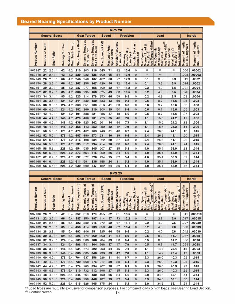
967147 22 2.2 : 1 42 4.2 210 203 116 545 71 92 15.4 0 .006 .00002967148 24 2.4 : 1 42 4.2 229 222 126 500 65 84 13.9 0 .008 .00002967149 26 2.6 : 1 66 4.2 248 240 137 462 60 77 12.9 0 0.1 3.8 6.9 .012 .0002967150 28 2.8 : 1 66 4.2 267 258 147 429 56 72 12.0 0 0.1 3.8 6.9 .014 .0002967151 30 3.0 : 1 85 4.2 287 277 158 400 52 67 11.2 0 0.2 4.9 8.5 .021 .0004967152 32 3.2 : 1 85 4.2 306 295 168 375 49 63 10.5 0 0.2 4.9 8.5 .025 .0004967153 34 3.4 : 1 85 4.2 325 314 179 353 46 59 9.9 0 0.2 4.9 8.5 .03 .0004967154 36 3.6 : 1 124 4.2 344 332 189 333 43 56 9.3 0 0.6 9.7 15.6 .05 .003967155 38 3.8 : 1 124 4.2 363 351 200 316 41 53 8.8 0 0.6 9.7 15.6 .05 .003967156 40 4.0 : 1 124 4.2 382 369 210 300 39 50 8.4 0 0.6 9.7 15.6 .06 .003967157 42 4.2 : 1 124 4.2 401 388 221 286 37 48 8.0 0 0.6 9.7 15.6 .07 .003967158 44 4.4 : 1 148 4.2 420 406 231 273 35 46 7.6 0 1.1 15.5 24.2 .11 .006967159 46 4.6 : 1 148 4.2 439 425 242 261 34 44 7.3 0 1.1 15.5 24.2 .12 .006967160 48 4.8 : 1 148 4.2 458 443 252 250 32 42 7.0 0 1.1 15.5 24.2 .14 .006967161 50 5.0 : 1 178 4.2 478 462 263 240 31 40 6.7 0 2.4 26.8 41.1 .18 .015967162 52 5.2 : 1 178 4.2 497 480 273 231 30 39 6.4 0 2.4 26.8 41.1 .20 .015967163 54 5.4 : 1 178 4.2 516 498 284 222 29 37 6.2 0 2.4 26.8 41.1 .22 .015967164 56 5.6 : 1 178 4.2 535 517 294 214 28 36 6.0 0 2.4 26.8 41.1 .24 .015967165 58 5.8 : 1 228 4.2 554 535 305 207 27 35 5.8 0 4.0 35.4 53.9 .33 .044967166 60 6.0 : 1 228 4.2 573 554 315 200 26 34 5.6 0 4.0 35.4 53.9 .36 .044967167 62 6.2 : 1 228 4.2 592 572 326 194 25 32 5.4 0 4.0 35.4 53.9 .39 .044967168 64 6.4 : 1 228 4.2 611 591 336 188 24 31 5.2 0 4.0 35.4 53.9 .43 .044967169 66 6.6 : 1 228 4.2 630 609 347 182 24 30 5.1 0 4.0 35.4 53.9 .46 .044
RPS 25
General Specs Gear Torque Speed Precision Load Inertia
Pro
duct
Num
ber
Num
ber
of T
eeth
Gea
r R
atio
Bea
ring
Num
ber
Mod
ule
ofG
ear
Teet
h (m
m)
Sta
tic T
orqu
e (N
m)
Dyn
amic
Tor
que
atM
IN L
ife (
Nm
)D
ynam
ic T
orqu
e at
MA
X L
ife (
Nm
)
Max
Spe
ed (
RP
M)
Max
Lub
e-Fr
ee
Spe
ed (
RP
M)
Ang
ular
Acc
urac
y(±
Arc
Sec
)O
ne-W
ay
Rep
eata
bilit
y(±
Arc
Sec
)A
ngul
ar B
ackl
ash
(±A
rcS
ec)
Max
Dyn
amic
M
omen
t Loa
d @
M
ax L
ife &
A
vg T
orqu
e (k
Nm
)M
ax D
ynam
ic
Rad
ial L
oad@
M
ax L
ife &
A
vg T
orqu
e (k
N)
Max
Dyn
amic
A
xial
Loa
d @
M
ax L
ife &
A
vg T
orqu
e (k
N)
Mom
ent o
f Ine
rtia
OU
TER
(kg
/m2 )
Mom
ent o
f Ine
rtia
INN
ER
(kg
/m2 )
967130 20 2.0 : 1 42 5.4 352 318 179 455 62 81 13.5 0 .011 .000019967131 22 2.2 : 1 66 5.4 387 350 197 414 57 73 12.2 0 0.1 2.8 5.9 .017 .00015967132 24 2.4 : 1 85 5.4 422 382 215 379 52 67 11.1 0 0.2 4.0 7.6 .027 .00039967133 26 2.6 : 1 85 5.4 458 414 233 350 48 62 10.4 0 0.2 4.0 7.6 .033 .00039967134 28 2.8 : 1 85 5.4 493 446 251 325 44 58 9.6 0 0.2 4.0 7.6 .042 .00039967135 30 3.0 : 1 124 5.4 528 478 269 303 41 54 8.9 0 0.5 8.8 14.7 .067 .0028967136 32 3.2 : 1 124 5.4 563 509 286 284 39 50 8.4 0 0.5 8.8 14.7 .080 .0028967137 34 3.4 : 1 124 5.4 598 541 304 268 37 47 7.9 0 0.5 8.8 14.7 .094 .0028967138 36 3.6 : 1 148 5.4 634 573 322 253 34 45 7.4 0 1.1 14.7 23.4 .15 .0063967139 38 3.8 : 1 148 5.4 669 605 340 239 33 42 7.0 0 1.1 14.7 23.4 .17 .0063967140 40 4.0 : 1 178 5.4 704 637 358 228 31 40 6.7 0 2.3 26.0 40.3 .22 .015967141 42 4.2 : 1 178 5.4 739 669 376 217 30 38 6.4 0 2.3 26.0 40.3 .25 .015967142 44 4.4 : 1 178 5.4 774 700 394 207 28 37 6.1 0 2.3 26.0 40.3 .29 .015967143 46 4.6 : 1 178 5.4 810 732 412 198 27 35 5.8 0 2.3 26.0 40.3 .32 .015967144 48 4.8 : 1 228 5.4 845 764 430 190 26 34 5.6 0 3.9 34.6 53.1 .44 .044967145 50 5.0 : 1 228 5.4 880 796 448 182 25 32 5.4 0 3.9 34.6 53.1 .50 .044967146 52 5.2 : 1 228 5.4 915 828 465 175 24 31 5.2 0 3.9 34.6 53.1 .54 .044
Geared Bearing Specifications by Product Number
(1)
(1) Load types are mutually exclusive for comparison purposes. For combined loads & high loads, see Bearing Load Section.(2) Contact Nexen
(1)
(1)
(1)
(1)
(1)
(2)
(2)
(2)
(2)
(2)
(2)
(2) (2) (2)

15
RPS 20
Part ID. Dimensions System Reaction Forces (Under Max. Torque Condition)
Pro
duct
Num
ber
Num
ber
of T
eeth
Gea
r To
oth
O.D
. Siz
e (m
m)
Out
put H
ole
Bol
t Circ
le Ø
(m
m)
Out
put P
ilot I
.D.
(mm
)M
ount
ing
Hol
eB
olt C
ircle
Ø (
mm
)M
ount
ing
Pilo
t I.D
.(m
m)
Pin
ion
Cen
ter
Dis
tanc
e (m
m)
Ove
rall
Hei
ght
(mm
)
Wei
ght/
Mas
s (k
g)
Ave
rage
S
epar
atio
n (N
)
Max
Sep
arat
ion
(N)
Ave
rage
Tor
que
Indu
ced
Rad
ial (
N)
Max
Tor
que
Indu
ced
Rad
ial (
N)
967147 22 152 60 50 28 20 98 42 2.6 824 1202 3125 3245967148 24 166 60 50 28 20 105 42 3.0 911 1244 3124 3237967149 26 178 85 75 45 35 111 43.5 3.6 896 1244 3125 3242967150 28 190 85 75 45 35 117 43.5 4.0 883 1245 3125 3246967151 30 202 107.5 95 65 55 123 43.5 4.7 872 1246 3126 3250967152 32 214 107.5 95 65 55 129 43.5 5.2 863 1246 3127 3253967153 34 226 107.5 95 65 55 135 43.5 5.7 854 1247 3127 3256967154 36 240 150 135 97 80 142 48 7.4 912 1275 3126 3250967155 38 252 150 135 97 80 148 48 8.0 903 1274 3127 3253967156 40 264 150 135 97 80 154 48 8.5 894 1273 3127 3256967157 42 276 150 135 97 80 160 48 9.1 886 1273 3128 3259967158 44 288 195 165 112 90 166 49.5 12.0 879 1272 3129 3261967159 46 300 195 165 112 90 172 49.5 12.0 873 1272 3129 3263967160 48 312 195 165 112 90 178 49.5 13.0 867 1271 3130 3265967161 50 326 220 195 139 115 185 51 15.0 909 1291 3128 3260967162 52 338 220 195 139 115 191 51 16.0 902 1290 3129 3262967163 54 350 220 195 139 115 197 51 17.0 896 1289 3130 3264967164 56 362 220 195 139 115 203 51 17.0 890 1288 3130 3266967165 58 374 275 250 184 160 209 55 21.0 885 1287 3131 3267967166 60 386 275 250 184 160 215 55 22.0 880 1287 3131 3269967167 62 400 275 250 184 160 222 55 23.0 914 1303 3130 3265967168 64 412 275 250 184 160 228 55 24.0 908 1301 3130 3266967169 66 424 275 250 184 160 234 55 25.0 903 1300 3131 3268
RPS 25
Part ID. Dimensions System Reaction Forces (Under Max. Torque Condition)
Pro
duct
Num
ber
Num
ber
of T
eeth
Gea
r To
oth
O.D
. Siz
e (m
m)
Out
put H
ole
Bol
t Circ
le Ø
(m
m)
Out
put P
ilot I
.D.
(mm
)M
ount
ing
Hol
eB
olt C
ircle
Ø (
mm
)M
ount
ing
Pilo
t I.D
.(m
m)
Pin
ion
Cen
ter
Dis
tanc
e (m
m)
Ove
rall
Hei
ght
(mm
)
Wei
ght/
Mas
s (k
g)
Ave
rage
S
epar
atio
n (N
)
Max
Sep
arat
ion
(N)
Ave
rage
Tor
que
Indu
ced
Rad
ial (
N)
Max
Tor
que
Indu
ced
Rad
ial (
N)
967130 20 174 60 50 28 20 115 54 4.0 1156 1662 4311 4473967131 22 190 85 75 65 35 123 55.5 5.0 1197 1691 4311 4474967132 24 206 107.5 95 65 55 131 55.5 6.0 1232 1715 4312 4474967133 26 220 107.5 95 65 55 138 55.5 6.7 1165 1698 4313 4487967134 28 236 107.5 95 65 55 146 55.5 7.4 1199 1720 4314 4486967135 30 252 150 135 97 80 154 60 9.6 1228 1739 4314 4486967136 32 268 150 135 97 80 162 60 11.0 1254 1756 4314 4485967137 34 282 150 135 97 80 169 60 11.0 1202 1740 4316 4495967138 36 298 195 165 112 90 177 61.5 15.0 1227 1755 4316 4494967139 38 314 195 165 112 90 185 61.5 16.0 1250 1769 4315 4494967140 40 328 220 195 139 115 192 63 18.0 1206 1755 4318 4502967141 42 344 220 195 139 115 200 63 19.0 1228 1768 4318 4501967142 44 360 220 195 139 115 208 63 20.0 1247 1780 4317 4500967143 46 374 220 195 139 115 215 63 22.0 1210 1767 4319 4507967144 48 390 275 250 184 160 223 67 26.0 1229 1778 4319 4506967145 50 406 275 250 184 160 231 67 27.0 1246 1788 4319 4505967146 52 420 275 250 184 160 238 67 28.0 1213 1776 4321 4512
Geared Bearing Dimensions & Specifications by Product Number
MOUNTING HOLEBOLT CIRCLE⌀
GEARTOOTHO.D. SIZE
OUTPUT HOLEBOLT CIRCLE⌀
PINIONCENTER
DISTANCE
OUTPUT PILOT I.D.
10 mm
MOUNTINGPILOT I.D.
OVERALLHEIGHT
SECTION A-A
A A
GREASEFITTINGS2 AT 180°
Basic gear dimensions shown for selection purposes only and subject to change. Go to www.nexengroup.com for detailed drawings and CAD models. If none of the products below meet your needs, contact Nexen and one can be designed to your specifications. Please contact Nexen for lead times.
Dimensions shown in mm unless otherwise noted.
Common Attributes for All Gears
Estimated Life See System Life section.Operating Temperature Range (°C) -5 to 40Tooth Grease Part Number 853901Gear Finish Black OxideBearing Finish SteelExternal Ratings/Standards CE, RoHS
Operational Noise (dB) up to 80 (speed dependent)
SeparationForce
PressureAngle
Radial Force(Resultant)
TangentialThrust Force
System Reaction Forces Under Maximum Torque Condition
16
RPS 32
General Specs Gear Torque Speed Precision Load Inertia
Pro
duct
Num
ber
Num
ber
of T
eeth
Gea
r R
atio
Bea
ring
Num
ber
Mod
ule
ofG
ear
Teet
h (m
m)
Sta
tic T
orqu
e (N
m)
Dyn
amic
Tor
que
atM
IN L
ife (
Nm
)
Dyn
amic
Tor
que
atM
AX
Life
(N
m)
Max
Spe
ed (
RP
M)
Max
Lub
e-Fr
ee
Spe
ed (
RP
M)
Ang
ular
Acc
urac
y(±
Arc
Sec
)O
ne-W
ay
Rep
eata
bilit
y(±
Arc
Sec
)A
ngul
ar B
ackl
ash
(±A
rcS
ec)
Max
Dyn
amic
M
omen
t Loa
d @
M
ax L
ife &
A
vg T
orqu
e (k
Nm
)M
ax D
ynam
ic
Rad
ial L
oad@
M
ax L
ife &
A
vg T
orqu
e (k
N)
Max
Dyn
amic
A
xial
Loa
d @
M
ax L
ife &
A
vg T
orqu
e (k
N)
Mom
ent o
f Ine
rtia
OU
TER
(kg
/m2 )
Mom
ent o
f Ine
rtia
INN
ER
(kg
/m2 )
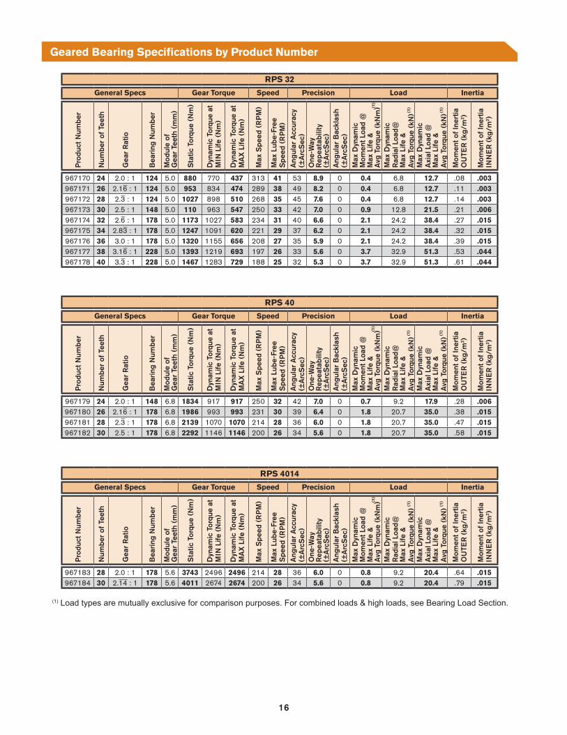
967170 24 2.0 : 1 124 5.0 880 770 437 313 41 53 8.9 0 0.4 6.8 12.7 .08 .003967171 26 2.16 : 1 124 5.0 953 834 474 289 38 49 8.2 0 0.4 6.8 12.7 .11 .003967172 28 2.3 : 1 124 5.0 1027 898 510 268 35 45 7.6 0 0.4 6.8 12.7 .14 .003967173 30 2.5 : 1 148 5.0 110 963 547 250 33 42 7.0 0 0.9 12.8 21.5 .21 .006967174 32 2.6 : 1 178 5.0 1173 1027 583 234 31 40 6.6 0 2.1 24.2 38.4 .27 .015967175 34 2.83 : 1 178 5.0 1247 1091 620 221 29 37 6.2 0 2.1 24.2 38.4 .32 .015967176 36 3.0 : 1 178 5.0 1320 1155 656 208 27 35 5.9 0 2.1 24.2 38.4 .39 .015967177 38 3.16 : 1 228 5.0 1393 1219 693 197 26 33 5.6 0 3.7 32.9 51.3 .53 .044967178 40 3.3 : 1 228 5.0 1467 1283 729 188 25 32 5.3 0 3.7 32.9 51.3 .61 .044
RPS 40
General Specs Gear Torque Speed Precision Load Inertia
Pro
duct
Num
ber
Num
ber
of T
eeth
Gea
r R
atio
Bea
ring
Num
ber
Mod
ule
ofG
ear
Teet
h (m
m)
Sta
tic T
orqu
e (N
m)
Dyn
amic
Tor
que
atM
IN L
ife (
Nm
)
Dyn
amic
Tor
que
atM
AX
Life
(N
m)
Max
Spe
ed (
RP
M)
Max
Lub
e-Fr
ee
Spe
ed (
RP
M)
Ang
ular
Acc
urac
y(±
Arc
Sec
)O
ne-W
ay
Rep
eata
bilit
y(±
Arc
Sec
)A
ngul
ar B
ackl
ash
(±A
rcS
ec)
Max
Dyn
amic
M
omen
t Loa
d @
M
ax L
ife &
A
vg T
orqu
e (k
Nm
)M
ax D
ynam
ic
Rad
ial L
oad@
M
ax L
ife &
A
vg T
orqu
e (k
N)
Max
Dyn
amic
A
xial
Loa
d @
M
ax L
ife &
A
vg T
orqu
e (k
N)
Mom
ent o
f Ine
rtia
OU
TER
(kg
/m2 )
Mom
ent o
f Ine
rtia
INN
ER
(kg
/m2 )
967179 24 2.0 : 1 148 6.8 1834 917 917 250 32 42 7.0 0 0.7 9.2 17.9 .28 .006967180 26 2.16 : 1 178 6.8 1986 993 993 231 30 39 6.4 0 1.8 20.7 35.0 .38 .015967181 28 2.3 : 1 178 6.8 2139 1070 1070 214 28 36 6.0 0 1.8 20.7 35.0 .47 .015967182 30 2.5 : 1 178 6.8 2292 1146 1146 200 26 34 5.6 0 1.8 20.7 35.0 .58 .015
RPS 4014
General Specs Gear Torque Speed Precision Load Inertia
Pro
duct
Num
ber
Num
ber
of T
eeth
Gea
r R
atio
Bea
ring
Num
ber
Mod
ule
ofG
ear
Teet
h (m
m)
Sta
tic T
orqu
e (N
m)
Dyn
amic
Tor
que
atM
IN L
ife (
Nm
)
Dyn
amic
Tor
que
atM
AX
Life
(N
m)
Max
Spe
ed (
RP
M)
Max
Lub
e-Fr
ee
Spe
ed (
RP
M)
Ang
ular
Acc
urac
y(±
Arc
Sec
)O
ne-W
ay
Rep
eata
bilit
y(±
Arc
Sec
)A
ngul
ar B
ackl
ash
(±A
rcS
ec)
Max
Dyn
amic
M
omen
t Loa
d @
M
ax L
ife &
A
vg T
orqu
e (k
Nm
)M
ax D
ynam
ic
Rad
ial L
oad@
M
ax L
ife &
A
vg T
orqu
e (k
N)
Max
Dyn
amic
A
xial
Loa
d @
M
ax L
ife &
A
vg T
orqu
e (k
N)
Mom
ent o
f Ine
rtia
OU
TER
(kg
/m2 )
Mom
ent o
f Ine
rtia
INN
ER
(kg
/m2 )
967183 28 2.0 : 1 178 5.6 3743 2496 2496 214 28 36 6.0 0 0.8 9.2 20.4 .64 .015967184 30 2.14 : 1 178 5.6 4011 2674 2674 200 26 34 5.6 0 0.8 9.2 20.4 .79 .015
Geared Bearing Specifications by Product Number
(1)
(1)
(1)
(1)
(1)
(1)
(1)
(1)
(1)
(1) Load types are mutually exclusive for comparison purposes. For combined loads & high loads, see Bearing Load Section.

17
RPS 32
Part ID. Dimensions System Reaction Forces (Under Max. Torque Condition)
Pro
duct
Num
ber
Num
ber
of T
eeth
Gea
r To
oth
O.D
. Siz
e (m
m)
Out
put H
ole
Bol
t Circ
le Ø
(m
m)
Out
put P
ilot I
.D.
(mm
)M
ount
ing
Hol
eB
olt C
ircle
Ø (
mm
)M
ount
ing
Pilo
t I.D
.(m
m)
Pin
ion
Cen
ter
Dis
tanc
e (m
m)
Ove
rall
Hei
ght
(mm
)
Wei
ght/
Mas
s (k
g)
Ave
rage
S
epar
atio
n (N
)
Max
Sep
arat
ion
(N)
Ave
rage
Tor
que
Indu
ced
Rad
ial (
N)
Max
Tor
que
Indu
ced
Rad
ial (
N)
967170 24 260 150 135 97 80 175 65.5 11.0 1771 2423 6833 7031967171 26 280 150 135 97 80 185 65.5 13.0 1809 2454 6834 7032967172 28 300 150 135 97 80 195 65.5 14.0 1843 2482 6834 7034967173 30 320 195 165 112 90 205 67 18.0 1872 2506 6835 7035967174 32 338 220 195 139 115 214 68.5 21.0 1804 2483 6839 7048967175 34 358 220 195 139 115 224 68.5 23.0 1834 2505 6839 7049967176 36 378 220 195 139 115 234 68.5 25.0 1861 2526 6839 7049967177 38 398 275 250 184 160 244 72.5 29.0 1884 2545 6839 7050967178 40 416 275 250 184 160 253 72.5 31.0 1829 2523 6843 7060
RPS 40
Part ID. Dimensions System Reaction Forces (Under Max. Torque Condition)
Pro
duct
Num
ber
Num
ber
of T
eeth
Gea
r To
oth
O.D
. Siz
e (m
m)
Out
put H
ole
Bol
t Circ
le Ø
(m
m)
Out
put P
ilot I
.D.
(mm
)M
ount
ing
Hol
eB
olt C
ircle
Ø (
mm
)M
ount
ing
Pilo
t I.D
.(m
m)
Pin
ion
Cen
ter
Dis
tanc
e (m
m)
Ove
rall
Hei
ght
(mm
)
Wei
ght/
Mas
s (k
g)
Ave
rage
S
epar
atio
n (N
)
Max
Sep
arat
ion
(N)
Ave
rage
Tor
que
Indu
ced
Rad
ial (
N)
Max
Tor
que
Indu
ced
Rad
ial (
N)
967179 24 331 195 165 112 90 222 84.5 23.0 1770 2369 6437 6627967180 26 355 220 195 139 115 234 86 27.0 1749 2371 6440 6636967181 28 379 220 195 139 115 246 86 30.0 1731 2373 6443 6644967182 30 403 220 195 139 115 258 86 33.0 1715 2374 6446 6651
RPS 4014
Part ID. Dimensions System Reaction Forces (Under Max. Torque Condition)
Pro
duct
Num
ber
Num
ber
of T
eeth
Gea
r To
oth
O.D
. Siz
e (m
m)
Out
put H
ole
Bol
t Circ
le Ø
(m
m)
Out
put P
ilot I
.D.
(mm
)M
ount
ing
Hol
eB
olt C
ircle
Ø (
mm
)M
ount
ing
Pilo
t I.D
.(m
m)
Pin
ion
Cen
ter
Dis
tanc
e (m
m)
Ove
rall
Hei
ght
(mm
)
Wei
ght/
Mas
s (k
g)
Ave
rage
S
epar
atio
n (N
)
Max
Sep
arat
ion
(N)
Ave
rage
Tor
que
Indu
ced
Rad
ial (
N)
Max
Tor
que
Indu
ced
Rad
ial (
N)
967183 28 376 220 195 139 115 258 113 39.0 3744 4870 14984 15305967184 30 402 220 195 139 115 271 113 44.0 3883 4963 14983 15298
Geared Bearing Dimensions & Specifications by Product Number
MOUNTING HOLEBOLT CIRCLE⌀
GEARTOOTHO.D. SIZE
OUTPUT HOLEBOLT CIRCLE⌀
PINIONCENTER
DISTANCE
OUTPUT PILOT I.D.
10 mm
MOUNTINGPILOT I.D.
OVERALLHEIGHT
SECTION A-A
A A
GREASEFITTINGS2 AT 180°
Basic gear dimensions shown for selection purposes only and subject to change. Go to www.nexengroup.com for detailed drawings and CAD models. If none of the products below meet your needs, contact Nexen and one can be designed to your specifications. Please contact Nexen for lead times.
Dimensions shown in mm unless otherwise noted.
Common Attributes for All Gears
Estimated Life See System Life section.Operating Temperature Range (°C) -5 to 40Tooth Grease Part Number 853901Gear Finish Black OxideBearing Finish SteelExternal Ratings/Standards CE, RoHS
Operational Noise (dB) up to 80 (speed dependent)
SeparationForce
PressureAngle
Radial Force(Resultant)
TangentialThrust Force
System Reaction Forces Under Maximum Torque Condition

18
Reaction Loading Calculations
SeparationForce
PressureAngle
Radial Force(Resultant)
TangentialThrust Force
Due to the unique rolling technology in the RPS system the pressure angle changes throughout the motion. Therefore, Nexen has provided both the average and maximum separation force and radial load force for each gear system. To calculate the values in your system simply multiple the catalog force by the ratio of your application torque/maximum torque. After the reaction forces are calculated, other application forces can be added to calculate bearing life and load. (See Bearing Loading section)
The calculations in the following section will allow you to calculate the Reaction Loading of the Geared Bearing & Pinion. These calculations will be nessesary to calculate the System Life on the following pages.
Calculating RPS Geared Bearing Reaction Loading
STEP 1: Gather the "System Reaction Forces Under Maximum Torque Condition data from the Specifications section.
System Reaction Forces Under Maximum Torque Condition
*Sample Data is from Specifications section: RPS Size 20, 64 Tooth Geared Bearing, Part# 967168
STEP 2: Enter the amount of torque needed for the application (up to, but not more than the maximum torque).
*Sample Data is from Specifications section: RPS Size 20, 64 Tooth Geared Bearing, Part# 967168
STEP 3: Calculate Resultant Forces.
*Sample Data is from Specifications section: RPS Size 20, 64 Tooth Geared Bearing, Part# 967168
****
****
Data from Specification Section Customer Data Sample Data*
Average Separation Force Under Max Torque N 908 N
Max Separation Force Under Max Torque N 1301 N
Average Torque Induced Radial Force Under Max Torque N 3130 N
Max Torque Induced Radial Force Under Max Torque N 3266 N
Sample Application Data Sample Data* Sample Resultant Forces
Average Separation Force Under Max Torque 908 (N) 54 (Nm) / 92.3 (Nm) = 531 N
Max Separation Force Under Max Torque 1301 (N) 54 (Nm) / 92.3 (Nm) = 761 N
Average Torque Induced Radial Force Under Max Torque 3130 (N) 54 (Nm) / 92.3 (Nm) = 1831 N
Max Torque Induced Radial Force Under Max Torque 3266 (N) 54 (Nm) / 92.3 (Nm) = 1911 N
Application Data Customer Data Sample Data*
Amount of Torque Required for Application Nm of Nm Max. 54 Nm of 92.3 Nm Max.
Application Data Customer Data Actual Resultant Forces
Average Separation Force Under Max Torque (N) (Nm) / (Nm) = N
Max Separation Force Under Max Torque (N) (Nm) / (Nm) = N
Average Torque Induced Radial Force Under Max Torque (N) (Nm) / (Nm) = N
Max Torque Induced Radial Force Under Max Torque (N) (Nm) / (Nm) = N

19
Static Safety factor
fS =
Static Bearing Load Capacity Calculations
FA0
FR0
TstaticApp
M0
Bearing Size GB42 GB66 GB85 GB124 GB148 GB178 GB228
Basic Dynamic Load Rating (C) N 7,350 17,500 20,300 33,100 49,100 80,300 104,000Basic Static Load Rating (C0) N 8,350 22,300 29,500 50,900 76,800 135,000 173,000
Rolling Diameter of Cross Roller (dp) m 0.0415 0.066 0.085 0.124 0.1475 0.178 0.2275
RPS Generated Load on Cross
Roller Bearing (frps)
RPS10 N 380 345 332 322 316 311 307 RPS12 N 748 679 653 633 622 612 603 RPS16 N 4,022 3,544 3,364 3,210 3,135 3,066 3,007 RPS20 N 5,120 4,433 4,173 3,941 3,834 3,737 3,650 RPS25 N 7,393 6,324 5,919 5,549 5,384 5,234 5,097 RPS32 N 9,024 8,711 8,428 8,162 RPS40 N 8,522 8,202 RPS4014 N 19,776
Table 1 Bearing Race Specific Data
Measurements for Bearing Calculations
Customer Data(record your values below)
Sample Data
Maximum Static Gear Torque of Application (TstaticApp) Nm 200 Nm
Dynamic Gear Torque at Min Life (Taccel) (from Specifications Section) Nm 306 Nm
Maximum Static Radial Load (FR0) N 0 N
Maximum Static Axial Load (FA0) N 5000 N
Maximum Static Moment Load (M0) Nm 1000 Nm
STEP 1: GATHER APPLICATION DATABefore you begin calculations, there are several key measurements that you will need from your application in order to calculate static safety factor. Collect the data and record it in the space provided.
Service Condition fS
Normal Load 1.5 to 2
Impact Load 2 to 3
STEP 3: APPLY SAFETY FACTORThe basic static load rating refers to the static load C0 with constant direction and magnitude, under which the calculated contact stress in the center of the contact area between the roller and the raceway where the maximum load applied is 4,000 MPa (if the deformation exceeds this level, it will affect rotation). When a load is statically or dynamically applied, it is necessary to consider the static safety factor.
Table 2 Static Safety Factor
STEP 2: CALCULATE THE STATIC EQUIVALENT RADIAL LOADPerform the following calculations using data from Table 1 and your application data from STEP 1.
Sample: = 20,427 N
MaxiMuM Static equivalent radial load
NP0 =
MAXIMUM STATIC EQUIVALENT RADIAL LOAD
∗
2 ∗
∗
2 ∗
∗
2 ∗
3210200306
10000.124
0
∗
2 ∗
∗
2 ∗
MAXIMUM STATIC EQUIVALENT RADIAL LOADUse Table 1 along with the calculation above to calculate the Maximum Static Equivalent Radial Load.
∗
2 ∗
Sample: = 2.49
50,900
20,427
5000
*
Sample: fS = 2.49 → Sufficient safety factor for impact loads.
*

20
Bearing Drag Torque Calculations
Bearing Size GB42 GB66 GB85 GB124 GB148 GB178 GB228
Basic Dynamic Load Rating (C) N 7,350 17,500 20,300 33,100 49,100 80,300 104,000
Basic Static Load Rating (C0) N 8,350 22,300 29,500 50,900 76,800 135,000 173,000
Rolling Diameter of Cross Roller (dp) m 0.0415 0.066 0.085 0.124 0.1475 0.178 0.2275
RPS Generated Load on Cross
Roller Bearing (frps)
RPS10 N 380 345 332 322 316 311 307
RPS12 N 748 679 653 633 622 612 603
RPS16 N 4,022 3,544 3,364 3,210 3,135 3,066 3,007
RPS20 N 5,120 4,433 4,173 3,941 3,834 3,737 3,650
RPS25 N 7,393 6,324 5,919 5,549 5,384 5,234 5,097
RPS32 N 9,024 8,711 8,428 8,162
RPS40 N 8,522 8,202
RPS4014 N 19,776
Table 3 Bearing Race Specific Data
Measurements forBearing Calculations
Customer Data(record your values below) Sample Data
Maximum Dynamic Gear Torqueof Application (TmaxApp) Nm 501 Nm
Dynamic Gear Torque at Min Life (Taccel) (from Specifications Section) Nm 501 Nm
Maximum Dynamic Radial Load (FRmax) N 0 N
Maximum Dynamic Axial Load (FAmax) N 54,300 NMaximum Dynamic Moment Load (Mmax) Nm 0 Nm
STEP 1: GATHER APPLICATION DATABefore you begin calculations, there are several key measurements that you will need from your application in order to calculate drag torque. Collect the data and record it in the space provided.
Loading Distribution IF:THEN:
X Y
1 0.45
0.67 0.67
∗
2 ∗∗
STEP 2: CALCULATE THE MAXIMUM DYNAMIC EQUIVALENT RADIAL LOADPerform the following calculations using the data from Table 3 and your application data from STEP 1.
Sample: = 38,395 N
MaxiMuM dynaMic equivalent radial load
NPCmax =
∗
2 ∗∗
∗
2 ∗∗
∗
2 ∗∗
MAXIMUM DYNAMIC EQUIVALENT RADIAL LOAD
0.2275
0.67501501
3007 .67 54,300
∗
2 ∗∗
FAmax
FRmax
TmaxApp
Mmax

21
STEP 3: DETERMINE BEARING DRAG TORQUEThe bearing drag torque can be estimated based on the dynamic equivalent radial load. Use the following charts to determine your approximate bearing drag torque. Add bearing drag torque to the application required gear torque to determine the total torque requirement. Verify your chosen geared bearing is still capable for the application.
Bearing Drag Torque Calculations
total required Gear torque
Nm
Sample: Total Required Torque = (501Nm) + (84 Nm) = 585 Nm
+
Dynamic
Equivalent
Radial
Load
vs.
Drag
Torque
0
50
100
150
200
250
Dynamic
Equivalent
Radial
Load
vs.
Drag
Torque
Bearing Number
GB124GB148GB178GB228
0 40,000 60,000 80,000 100,000 120,000
Maximum Dynamic Equivalent Radial Load (N)
Maximum Dynamic Equivalent Radial Load (N)
Bea
ring
Dra
g To
rque
(Nm
)B
earin
g D
rag
Torq
ue (N
m)
00
5
10
15
20
25
5,000 10,000 15,000 20,000 25,000
20,000
Bearing Number
GB42GB66GB85
MAXIMUM DYNAMIC EQUIVALENT RADIAL LOAD VS. DRAG TORQUE
Dynamic
Equivalent
Radial
Load
vs.
Drag
Torque
0
50
100
150
200
250
Dynamic
Equivalent
Radial
Load
vs.
Drag
Torque
Bearing Number
GB124GB148GB178GB228
0 40,000 60,000 80,000 100,000 120,000
Maximum Dynamic Equivalent Radial Load (N)
Maximum Dynamic Equivalent Radial Load (N)
Bea
ring
Dra
g To
rque
(Nm
)B
earin
g D
rag
Torq
ue (N
m)
00
5
10
15
20
25
5,000 10,000 15,000 20,000 25,000
20,000
Bearing Number
GB42GB66GB85
TOTAL REQUIRED GEAR TORQUE
Sample
Sample: TBD = 84 Nm
~84 Nm
38395 N
TTgear = ( Tp ) + ( TBD )
TTgear =TTgear = ( )Nm ( )Nm
Use your Application Gear Torque (Tp) and Bearing Drag Torque (TBD) calculated above to determine the Total Required Gear Torque.
BearinG draG torque
Nm
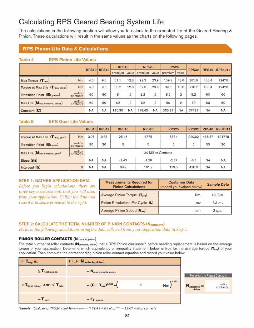
22
IF Tavg is: THEN Ncontacts, pinion:
< Tfinal, pinion = Nmax contacts, pinion
> Tfinal, pinion AND < Tmax = (C ÷ Tavg)3.333 =
= Tmax = ET , pinion
PINION ROLLER CONTACTS (Ncontacts, pinion)The total number of roller contacts (Ncontacts, pinion) that a RPS Pinion can sustain before needing replacement is based on the average torque of your application. Determine which equivalency or inequality statement below is true for the average torque (Tavg) of your application. Then complete the corresponding pinion roller contact equation and record your value below.
3.333
÷ Nm
RPS10 RPS12RPS16 RPS20 RPS25
RPS32 RPS40 RPS4014premium value premium value premium value
Max Torque (Tmax) Nm 4.0 9.5 61.1 12.8 92.3 23.9 159.2 43.8 385.0 458.4 1247.8
Torque at Max Life (Tfinal, pinion) Nm 4.0 9.5 33.7 12.8 52.5 23.9 89.5 43.8 218.7 458.4 1247.8
Transition Point (ET, pinion) million contacts 60 60 8 2 8.2 2 8.5 2 9.2 60 60
Max Life (Nmax contacts, pinion) million contacts 60 60 60 2 60 2 60 2 60 60 60
Constant (C) NA NA 115.30 NA 179.43 NA 305.91 NA 747.91 NA NA
Table 4 RPS Pinion Life Values
Pinion life in roller contactS
Ncontacts, = pinion
Measurements Required for Pinion Calculations
Customer Data(record your values below)
Sample Data
Average Pinion Torque (Tavg) Nm 85 Nm
Pinion Revolutions Per Cycle (L) rev 1.3 rev
Average Pinion Speed (Vavg) rpm 2 rpm
STEP 1: GATHER APPLICATION DATABefore you begin calculations, there are three key measurements that you will need from your application. Collect the data and record it in space provided to the right.
STEP 2: CALCULATE THE TOTAL NUMBER OF PINION CONTACTS (NCONTACTS)Perform the following calculations using the data collected from your application data in Step 1.
The calculations in the following section will allow you to calculate the expected life of the Geared Bearing & Pinion. These calculations will result in the same values as the charts on the following pages.
Calculating RPS Geared Bearing System Life
RPS Pinion Life Data & Calculations
million contacts
Sample: (Evaluating RPS20 size) Ncontacts, pinion = (179.43 ÷ 85 Nm)3.333 = 12.07 million contacts
RPS10 RPS12 RPS16 RPS20 RPS25 RPS32 RPS40 RPS4014
Torque at Max Life (Tfinal, gear) Nm 3.98 9.55 25.46 47.75 87.54 220.02 458.37 1247.78
Transition Point (ET, gear) million contacts 30 30 5 5 5 5 30 30
Max Life (Nmax contacts, gear) million contacts 30 Million Contacts
Slope (m) NA NA -1.43 -1.78 -2.87 -6.6 NA NA
Intercept (b) N NA NA 68.2 101.2 173.5 418.0 NA NA
Table 5 RPS Gear Life Values

23
RPS Pinion/Gear Life Calculations
EXACT OPTION: PINION LIFE IN HOURS (Nhours)
Use Table 7 along with the data you collected above to calculate the total number of service hours your pinion can provide before needing replacement. First calculate E1 to use in the Nhours equation.
Pinion life in HourS
• 106 • NmNhours = ÷ rpm hrs60 • • Nhours =
Nrev=
E1 = round up LMust round E1 up to the nearest whole integer.
PINION LIFE IN PINION REVOLUTIONS (Nrev) Nrev = Ncontacts, pinion
Pinion life in revolutionS
E1 =
STEP 4: CONVERT ROLLER CONTACTS TO HOURS, METERS OR REVOLUTIONSThere are two options for converting contacts to other units: exact and estimated. Exact should be used whenever possible. The estimation is available for customers who do not have a well-defined distance per cycle.
ESTIMATION OPTION & LIFE IN PINION REVOLUTIONSThese calculations assume the pinion travels nonstop in one direction throughout its whole life.
Nhours = (Ncontacts, pinion • 106 • L) ÷ (60 • E1 • Vavg)
rev =
million contacts
million revolutions
round up
Sample: Nrev = 12.07 million revolutions
Sample: Nhours = (12.07 • 106 • 1.3) ÷ (60 • 2 • 2) = 65,379 hrs
Sample: E1 = Round up (1.3 rev) = 2 rev
IF Tavg is: THEN Ncontacts, gear :
< Tfinal, gear = Nmax contacts, gear
> Tfinal, gear AND < Tmax = (Tavg – b) ÷ m =
= Tmax = ET , gear
GEAR TOOTH CONTACTS (Ncontacts, gear)
The total number of tooth contacts (Ncontacts, gear) that a RPS Gear can sustain before needing replacement may be calculated with average pinion torque. Use Table 8 to determine which equivalency or inequality statement below is true for the average torque (Tavg) of your application. Then complete the corresponding gear tooth contact formula and record your value below.
Gear life in tootH contactS
÷ Ncontacts, = gear
STEP 3: CALCULATE THE TOTAL NUMBER OF TOOTH CONTACTSPerform the following calculations using the data collected from your application and the values from Tables 7 & 8.
– NN million contacts
Sample: (Evaluating RPS20 size) Ncontacts, gear = (85 N – 101.2) ÷ -1.78 = 9.10 million contacts
rev
rev
rev

24
Refer to the following charts for a quick comparison of Life vs. Load for each RPS system. Exact calculations for the expected life of the Geared Bearing & Pinion are available on the previous pages.
0 20 40 60Roller Contacts (Millions) 0 10 20 30
Tooth Contacts (Millions)
0 10 20 30Tooth Contacts (Millions)
0 20 40 60Roller Contacts (Millions)
Premium
0 10 20 30Tooth Contacts (Millions)
0 20 40 60Roller Contacts (Millions)
PINION LIFEGEAR LIFE
PINION LIFEGEAR LIFE
Premium
0.0
1.6
3.2
4.8
6.4
RPS12-GB System Life Graph
RPS10-GB System Life Graph
RPS16-GB System Life Graph
Premium Premium
PINION LIFEGEAR LIFE
Premium
0.0
3.8
7.6
11.5
15.3
0.0
12.7
25.5
38.2
50.9
63.7
76.4
Premium
Value
PinionTorque(Nm)
PinionTorque(Nm)
PinionTorque(Nm)
Geared Bearing System Life Graphs (RPS10, 12 & 16)

25
0 20 40 60Roller Contacts (Millions)
0 10 20 30Tooth Contacts (Millions)
PinionTorque(Nm)
0 20 40 60Roller Contacts (Millions)
0 10 20 30
Tooth Contacts (Millions)
0 10 20 30Tooth Contacts (Millions)
0 20 40 60Roller Contacts (Millions)
PINION LIFEGEAR LIFE
PINION LIFEGEAR LIFE
PINION LIFEGEAR LIFE
0.0
61.1
122.2
183.3
244.5
305.6
366.7
427.8Premium
Premium
Premium
Premium
PremiumValue
PinionTorque(Nm)
0.0
15.9
31.8
47.7
63.7
79.6
95.5
111.4
0.0
39.8
79.6
119.4
159.2
198.9
RPS20-GB System Life Graph
RPS25-GB System Life Graph
RPS32-GB System Life Graph
PremiumValue
PinionTorque(Nm)
Geared Bearing System Life Graphs (RPS20, 25 & 32)

26
Geared Bearing System Life Graphs (RPS40 & 4014)
RPS40-GB System Life Graph
RPS4014-GB System Life Graph
0 10 20 30Tooth Contacts (Millions)
0 20 40 60Roller Contacts (Millions)
0 10 20 30Tooth Contacts (Millions)
0 20 40 60Roller Contacts (Millions)
PINION LIFEGEAR LIFE
PINION LIFEGEAR LIFE
Premium, Standard & Endurance
0.0
445.6
891.3
1336.9
1782.5
2228.2
Premium
0.0
305.6
458.4
152.8
611.2
764.0
916.7
Premium, Standard & Endurance
Premium
PinionTorque(Nm)
PinionTorque(Nm)
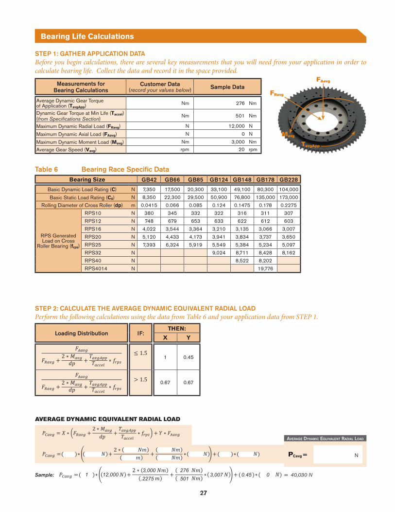
27
Bearing Life Calculations
Bearing Size GB42 GB66 GB85 GB124 GB148 GB178 GB228
Basic Dynamic Load Rating (C) N 7,350 17,500 20,300 33,100 49,100 80,300 104,000
Basic Static Load Rating (C0) N 8,350 22,300 29,500 50,900 76,800 135,000 173,000
Rolling Diameter of Cross Roller (dp) m 0.0415 0.066 0.085 0.124 0.1475 0.178 0.2275
RPS Generated Load on Cross
Roller Bearing (frps)
RPS10 N 380 345 332 322 316 311 307
RPS12 N 748 679 653 633 622 612 603
RPS16 N 4,022 3,544 3,364 3,210 3,135 3,066 3,007
RPS20 N 5,120 4,433 4,173 3,941 3,834 3,737 3,650
RPS25 N 7,393 6,324 5,919 5,549 5,384 5,234 5,097
RPS32 N 9,024 8,711 8,428 8,162
RPS40 N 8,522 8,202
RPS4014 N 19,776
Table 6 Bearing Race Specific Data
Measurements forBearing Calculations
Customer Data(record your values below) Sample Data
Average Dynamic Gear Torqueof Application (TavgApp) Nm 276 Nm
Dynamic Gear Torque at Min Life (Taccel)(from Specifications Section)
Nm 501 Nm
Maximum Dynamic Radial Load (FRavg) N 12,000 N
Maximum Dynamic Axial Load (FAavg) N 0 N
Maximum Dynamic Moment Load (Mavg) Nm 3,000 Nm
Average Gear Speed (Vavg) rpm 20 rpm
STEP 1: GATHER APPLICATION DATABefore you begin calculations, there are several key measurements that you will need from your application in order to calculate bearing life. Collect the data and record it in the space provided.
STEP 2: CALCULATE THE AVERAGE DYNAMIC EQUIVALENT RADIAL LOADPerform the following calculations using the data from Table 6 and your application data from STEP 1.
Sample: = 40,030 N
∗
2 ∗∗
averaGe dynaMic equivalent radial load
NPCavg =
∗
2 ∗∗
∗
2 ∗∗
0.45 03,007
276501
3,000.2275
12,0001
AVERAGE DYNAMIC EQUIVALENT RADIAL LOAD
Loading Distribution IF:THEN:
X Y
1 0.45
0.67 0.67
∗
2 ∗∗
∗
2 ∗∗
FAavg
FRavg
TavgApp
Mavg

28
Bearing Life Calculations
STEP 3: CALCULATE THE BEARING RACE LIFEThe bearing race life is the total number of revolutions or hours that 90% of a group of identical geared bearings independently operating under the same conditions can achieve without showing flaking from rolling fatigue on the cross roller raceways.
Service Condition, IF:THEN:
fw
Smooth motion without impact 1 to 1.2
Normal motion 1.2 to 1.5Motion with severe impact 1.5 to 3
BEARING RACE LIFE IN REVOLUTIONSUse Table 6 along with the data you collected above to calculate the Bearing Race Life in Revolutions.
Sample: = 13.1 million revolutions
/
/
1.0 104,0001.2 40,030
BearinG race life in revolutionS
millionrevolutionsNrev =
/
/
/
/
Sample: = 10,917 hrs
BearinG race life in HourS
hrsNhours =
/
/
/
/
/
/
13.1 20
BEARING RACE LIFE IN HOURSUse Table 6 along with the data you collected above to calculate the Bearing Race Life in Hours.
100 150 200 250
Temperature of the bearing unit (°C)
Note: The normal service temperature is 80°C or below.If the product is to be used at a higher temperature, contact Nexen.
1.00.90.80.70.60.5
Tem
pera
ture
fact
or (f
T)
Bearing Operating Temperature Graph

29

30
ISO 9001 Certified
Nexen has sales offices throughout the United States, Europe, Japan, and Australia.
www.nexengroup.com
In accordance with Nexen’s established policy of constant product improvement, the specifications contained in this document are subject to change without notice. Technical data listed in this document are based on the latest information available at the time of printing and are also subject to change without notice. For current information, please consult www.nexengroup.com or contact Nexen’s Technical Support Group at the location to the right.
Nexen Group, Inc.560 Oak Grove ParkwayVadnais Heights, MN 55127
(800) 843-7445Fax: (651) 286-1099www.nexengroup.com
©2017 Nexen Group, Inc. FORM NO. L-21604-B-0717
CUTTING SYSTEMS
GANTRY SYSTEMS
MEDICAL PRODUCTS
ROBOTICS
AEROSPACE
MACHINE TOOL
SEMICONDUCTOR
MATERIAL HANDLING
INDUSTRIES & APPLICATIONS