ZeptoProg User Guide - MattairTech LLC · ZeptoProg™ User Guide AVR Studio / AVRISPmkII driver...
46
ZeptoProg™ User Guide September 20, 2012 1 http://www.mattairtech.com/
Transcript of ZeptoProg User Guide - MattairTech LLC · ZeptoProg™ User Guide AVR Studio / AVRISPmkII driver...
ZeptoProg™ User Guide
September 20, 2012 1 http://www.mattairtech.com/
ZeptoProg™ User Guide
Table of ContentsTable of ContentsOverview........................................................................................................................4
Introduction............................................................................................................... ........................44 tools in 1................................................................................................................................... ......4Features............................................................................................................................... .............6
About..............................................................................................................................7Contact Information............................................................................................................... ............7Support Information......................................................................................................................... ..7Precautions.................................................................................................................... ...................7
Windows Installation....................................................................................................8WinAVR / AVRDUDE..................................................................................................................... ....8AVR Studio / AVRISPmkII driver....................................................................................................... .9FLIP / DFU Bootloader Driver................................................................................................ ..........10ZeptoProg Driver / Serial Configuration................................................................... ........................11Terminal Emulator............................................................................................. ..............................13
Linux Installation........................................................................................................14Drivers............................................................................................................................... ..............14GCC Toolchain........................................................................................................... .....................14AVRDUDE...................................................................................................................... .................14dfuprogrammer........................................................................................................................ .......14Terminal Emulator............................................................................................................................ 14
ZeptoProg Hardware...................................................................................................15Layout / Header Pins..................................................................................................... ..................15Pin Descriptions................................................................................................. .............................16Buttons........................................................................................................................ ....................17LEDs.................................................................................................................... ...........................18
Configuration..............................................................................................................19AVR Programmer........................................................................................................20
Configuration........................................................................................................................... ........20Connecting Target Board............................................................................................................... ..20Using AVR Studio.................................................................................................................. ..........21Using AVRDUDE....................................................................................................................... ......25
GPIO App.....................................................................................................................26GPIO App Configuration............................................................................................................... ...26GPIO Pin Connections............................................................................................. .......................27Pin Configuration...................................................................................................................... .......27Timer Configuration................................................................................................................... ......28Input................................................................................................................................... .............29Output........................................................................................................................ .....................29PWM........................................................................................................................... ....................30
September 20, 2012 2 http://www.mattairtech.com/
ZeptoProg™ User Guide
Frequency Output.......................................................................................................................... ..32Frequency Measurement............................................................................................................... ..33
Serial App....................................................................................................................35Serial App Configuration..................................................................................... ............................35Serial Connections......................................................................................................... .................36
SPI App........................................................................................................................37SPI App Configuration.......................................................................................................... ...........37SPI Connections.............................................................................................................................. 37SPI Commands................................................................................................................ ...............38SPI Transfer........................................................................................................... .........................38SPI Write.......................................................................................................................... ...............39SPI Read................................................................................................................................... ......39Example Session.............................................................................................. ..............................40
DFU Bootloader...........................................................................................................41FLIP............................................................................................................................................. ....41dfuprogrammer................................................................................................. .............................43
Legal Notices..............................................................................................................44Copyright Notices................................................................................................................ ............44Software Disclaimer................................................................................................ ........................44Hardware Disclaimer........................................................................................................ ...............44Trademarks............................................................................................................... ......................44Acknowledgments......................................................................................................... ..................44
Appendix A: Powering Target via ZeptoProg 5V.....................................................45Appendix B: AVR Programmer Supported Devices................................................46
September 20, 2012 3 http://www.mattairtech.com/
ZeptoProg™ User Guide
OverviewOverview
Introduction
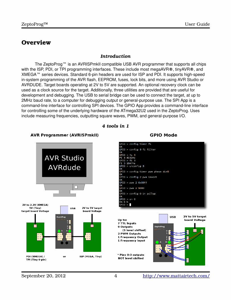
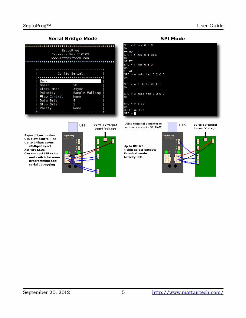
The ZeptoProg™ is an AVRISPmkII compatible USB AVR programmer that supports all chips with the ISP, PDI, or TPI programming interfaces. These include most megaAVR®, tinyAVR®, and XMEGA™ series devices. Standard 6pin headers are used for ISP and PDI. It supports highspeed insystem programming of the AVR flash, EEPROM, fuses, lock bits, and more using AVR Studio or AVRDUDE. Target boards operating at 2V to 5V are supported. An optional recovery clock can be used as a clock source for the target. Additionally, three utilities are provided that are useful for development and debugging. The USB to serial bridge can be used to connect the target, at up to 2MHz baud rate, to a computer for debugging output or generalpurpose use. The SPI App is a commandline interface for controlling SPI devices. The GPIO App provides a commandline interface for controlling some of the underlying hardware of the ATmega32U2 used in the ZeptoProg. Uses include measuring frequencies, outputting square waves, PWM, and generalpurpose I/O.
4 tools in 1
September 20, 2012 4 http://www.mattairtech.com/
ZeptoProg™ User Guide
September 20, 2012 5 http://www.mattairtech.com/
ZeptoProg™ User Guide
Features
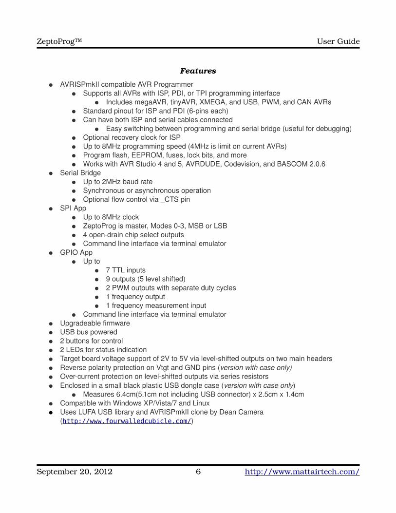
● AVRISPmkII compatible AVR Programmer● Supports all AVRs with ISP, PDI, or TPI programming interface
● Includes megaAVR, tinyAVR, XMEGA, and USB, PWM, and CAN AVRs● Standard pinout for ISP and PDI (6pins each)● Can have both ISP and serial cables connected
● Easy switching between programming and serial bridge (useful for debugging)● Optional recovery clock for ISP● Up to 8MHz programming speed (4MHz is limit on current AVRs)● Program flash, EEPROM, fuses, lock bits, and more● Works with AVR Studio 4 and 5, AVRDUDE, Codevision, and BASCOM 2.0.6
● Serial Bridge● Up to 2MHz baud rate● Synchronous or asynchronous operation● Optional flow control via _CTS pin
● SPI App● Up to 8MHz clock● ZeptoProg is master, Modes 03, MSB or LSB● 4 opendrain chip select outputs● Command line interface via terminal emulator
● GPIO App● Up to
● 7 TTL inputs● 9 outputs (5 level shifted)● 2 PWM outputs with separate duty cycles● 1 frequency output● 1 frequency measurement input
● Command line interface via terminal emulator● Upgradeable firmware● USB bus powered● 2 buttons for control● 2 LEDs for status indication● Target board voltage support of 2V to 5V via levelshifted outputs on two main headers● Reverse polarity protection on Vtgt and GND pins (version with case only)● Overcurrent protection on levelshifted outputs via series resistors● Enclosed in a small black plastic USB dongle case (version with case only)
● Measures 6.4cm(5.1cm not including USB connector) x 2.5cm x 1.4cm● Compatible with Windows XP/Vista/7 and Linux● Uses LUFA USB library and AVRISPmkII clone by Dean Camera
(http://www.fourwalledcubicle.com/)
September 20, 2012 6 http://www.mattairtech.com/
ZeptoProg™ User Guide
AboutAbout
Contact InformationJustin MattairMattairTech LLCPO Box 1079Heppner, OR 97836 [email protected]://www.mattairtech.com/
Support Information
The ZeptoProg firmware is currently still under development. New features are planned (ie: a simple logic analyzer). Please check the MattairTech website (http://www.MattairTech.com/) for updates. Email me if you have any feature requests, suggestions, or if you have found a bug. If you need support, please contact me (email is best). You can also find support information at the MattairTech website. Support for AVRs in general can be found at AVRfreaks (http://www.avrfreaks.net/). There, I monitor the forums section as the user physicist.
Precautions
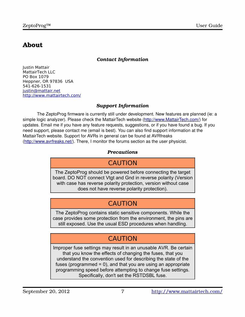
CAUTIONThe ZeptoProg should be powered before connecting the target
board. DO NOT connect Vtgt and Gnd in reverse polarity (Version with case has reverse polarity protection, version without case
does not have reverse polarity protection).
CAUTIONThe ZeptoProg contains static sensitive components. While the
case provides some protection from the environment, the pins are still exposed. Use the usual ESD procedures when handling.
CAUTIONImproper fuse settings may result in an unusable AVR. Be certain
that you know the effects of changing the fuses, that you understand the convention used for describing the state of the fuses (programmed = 0), and that you are using an appropriate programming speed before attempting to change fuse settings.
Specifically, don't set the RSTDSBL fuse.
September 20, 2012 7 http://www.mattairtech.com/
ZeptoProg™ User Guide
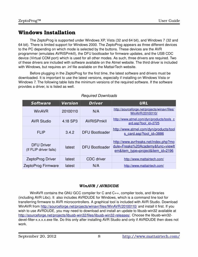
Windows InstallationWindows InstallationThe ZeptoProg is supported under Windows XP, Vista (32 and 64 bit), and Windows 7 (32 and
64 bit). There is limited support for Windows 2000. The ZeptoProg appears as three different devices to the PC depending on which mode is selected by the buttons. These devices are the AVR programmer (emulates AVRISPmkII), the DFU bootloader for firmware updates, and the USB CDC device (Virtual COM port) which is used for all other modes. As such, three drivers are required. Two of these drivers are included with software available on the Atmel website. The third driver is included with Windows, but requires an .inf file available on the MattairTech website.
Before plugging in the ZeptoProg for the first time, the latest software and drivers must be downloaded. It is important to use the latest versions, especially if installing on Windows Vista or Windows 7. The following table lists the minimum versions of the required software. If the software provides a driver, is is listed as well.
Required Downloads
Software Version Driver URL
WinAVR 20100110 N/A http://sourceforge.net/projects/winavr/files/WinAVR/20100110/
AVR Studio 4.18 SP3 AVRISPmkII http://www.atmel.com/dyn/products/tools_card.asp?tool_id=2725
FLIP 3.4.2 DFU Bootloaderhttp://www.atmel.com/dyn/products/tool
s_card.asp?tool_id=3886
DFU Driver(If FLIP driver fails)
latest DFU Bootloaderhttp://www.avrfreaks.net/index.php?module=Freaks%20Academy&func=viewItem&item_type=project&item_id=2196
ZeptoProg Driver latest CDC driver http://www.mattairtech.com/
ZeptoProg Firmware latest N/A http://www.mattairtech.com/
WinAVR / AVRDUDE
WinAVR contains the GNU GCC compiler for C and C++, compiler tools, and libraries (including AVR Libc). It also includes AVRDUDE for Windows, which is a command line tool for transferring firmware to AVR microcontrollers. A graphical tool is included with AVR Studio. Download WinAVR from http://sourceforge.net/projects/winavr/files/WinAVR/20100110/ and install it first. If you wish to use AVRDUDE, you may need to download and install an update to libusbwin32 available at http://sourceforge.net/projects/libusbwin32/files/libusbwin32releases/. Choose the libusbwin32develfilterx.x.x.x.exe file. Do this only after installing AVR Studio and only if AVRDUDE then does not work.
September 20, 2012 8 http://www.mattairtech.com/
ZeptoProg™ User Guide
AVR Studio / AVRISPmkII driver
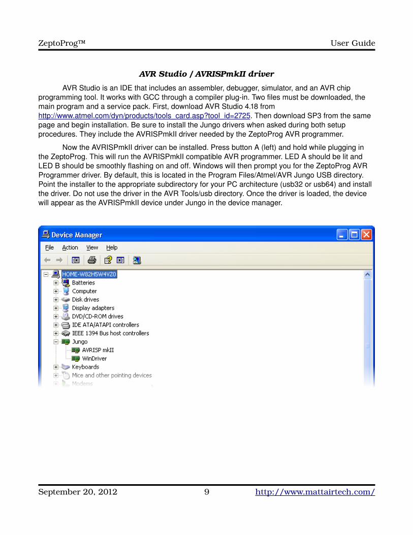
AVR Studio is an IDE that includes an assembler, debugger, simulator, and an AVR chip programming tool. It works with GCC through a compiler plugin. Two files must be downloaded, the main program and a service pack. First, download AVR Studio 4.18 from http://www.atmel.com/dyn/products/tools_card.asp?tool_id=2725. Then download SP3 from the same page and begin installation. Be sure to install the Jungo drivers when asked during both setup procedures. They include the AVRISPmkII driver needed by the ZeptoProg AVR programmer.
Now the AVRISPmkII driver can be installed. Press button A (left) and hold while plugging in the ZeptoProg. This will run the AVRISPmkII compatible AVR programmer. LED A should be lit and LED B should be smoothly flashing on and off. Windows will then prompt you for the ZeptoProg AVR Programmer driver. By default, this is located in the Program Files/Atmel/AVR Jungo USB directory. Point the installer to the appropriate subdirectory for your PC architecture (usb32 or usb64) and install the driver. Do not use the driver in the AVR Tools/usb directory. Once the driver is loaded, the device will appear as the AVRISPmkII device under Jungo in the device manager.
September 20, 2012 9 http://www.mattairtech.com/
ZeptoProg™ User Guide
FLIP / DFU Bootloader Driver
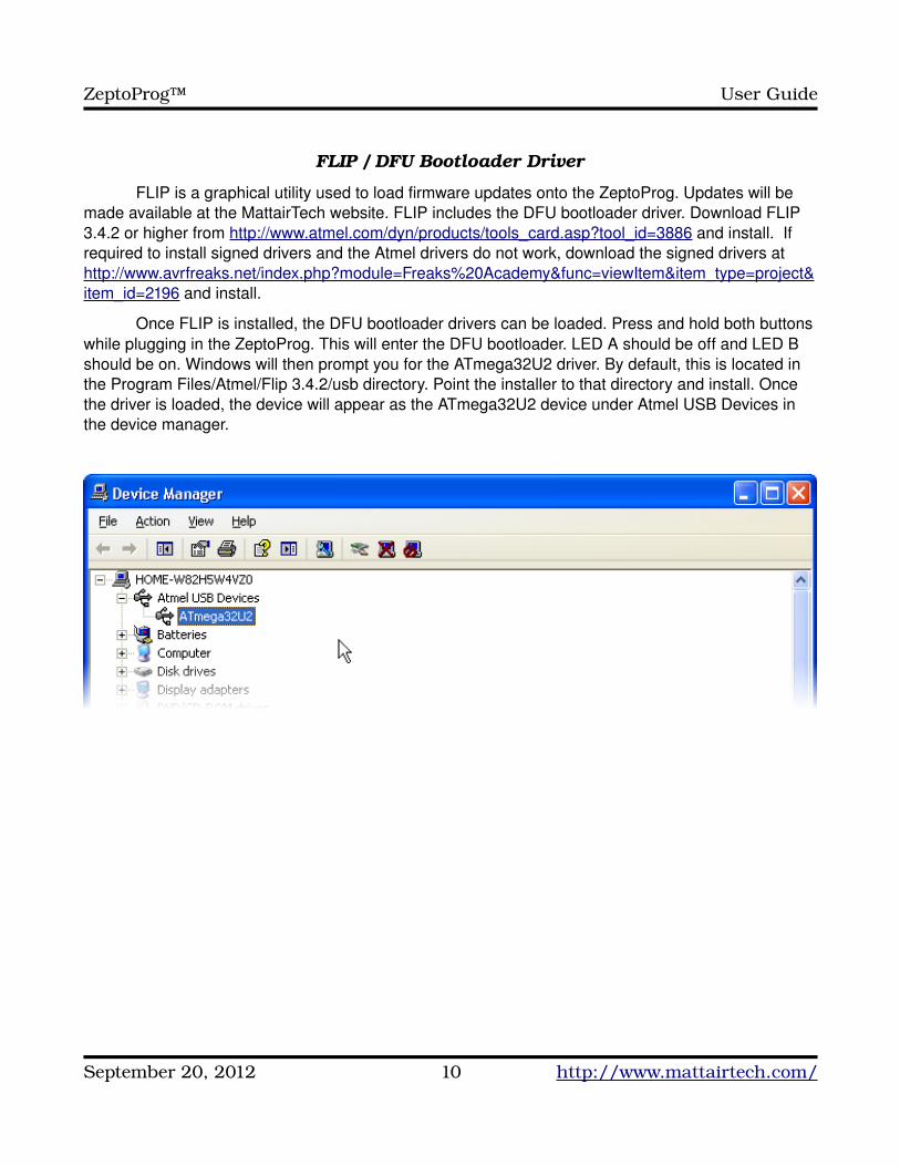
FLIP is a graphical utility used to load firmware updates onto the ZeptoProg. Updates will be made available at the MattairTech website. FLIP includes the DFU bootloader driver. Download FLIP 3.4.2 or higher from http://www.atmel.com/dyn/products/tools_card.asp?tool_id=3886 and install. If required to install signed drivers and the Atmel drivers do not work, download the signed drivers at http://www.avrfreaks.net/index.php?module=Freaks%20Academy&func=viewItem&item_type=project&item_id=2196 and install.
Once FLIP is installed, the DFU bootloader drivers can be loaded. Press and hold both buttons while plugging in the ZeptoProg. This will enter the DFU bootloader. LED A should be off and LED B should be on. Windows will then prompt you for the ATmega32U2 driver. By default, this is located in the Program Files/Atmel/Flip 3.4.2/usb directory. Point the installer to that directory and install. Once the driver is loaded, the device will appear as the ATmega32U2 device under Atmel USB Devices in the device manager.
September 20, 2012 10 http://www.mattairtech.com/
ZeptoProg™ User Guide
ZeptoProg Driver / Serial Configuration
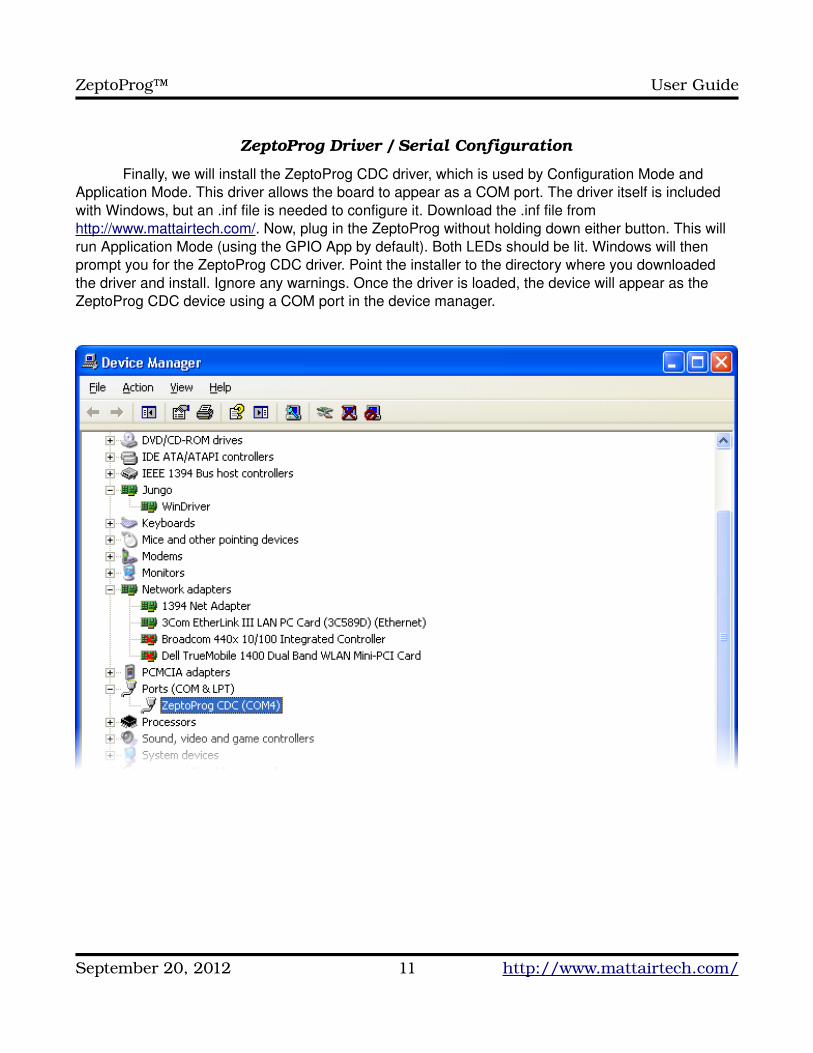
Finally, we will install the ZeptoProg CDC driver, which is used by Configuration Mode and Application Mode. This driver allows the board to appear as a COM port. The driver itself is included with Windows, but an .inf file is needed to configure it. Download the .inf file from http://www.mattairtech.com/. Now, plug in the ZeptoProg without holding down either button. This will run Application Mode (using the GPIO App by default). Both LEDs should be lit. Windows will then prompt you for the ZeptoProg CDC driver. Point the installer to the directory where you downloaded the driver and install. Ignore any warnings. Once the driver is loaded, the device will appear as the ZeptoProg CDC device using a COM port in the device manager.
September 20, 2012 11 http://www.mattairtech.com/
ZeptoProg™ User Guide
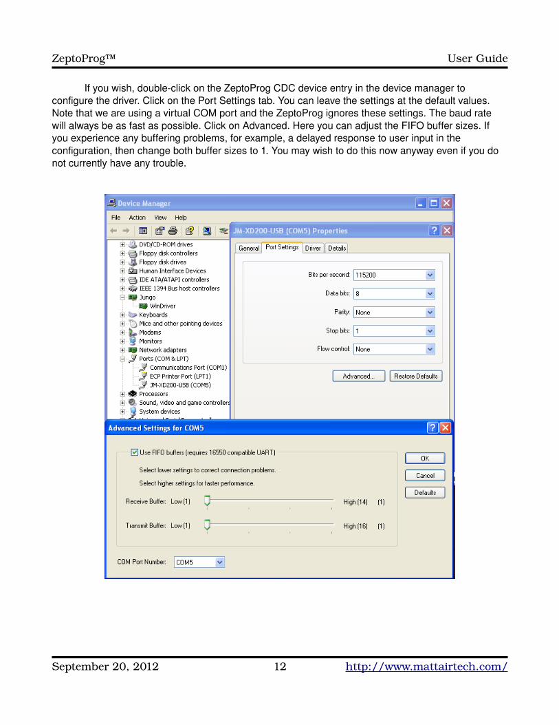
If you wish, doubleclick on the ZeptoProg CDC device entry in the device manager to configure the driver. Click on the Port Settings tab. You can leave the settings at the default values. Note that we are using a virtual COM port and the ZeptoProg ignores these settings. The baud rate will always be as fast as possible. Click on Advanced. Here you can adjust the FIFO buffer sizes. If you experience any buffering problems, for example, a delayed response to user input in the configuration, then change both buffer sizes to 1. You may wish to do this now anyway even if you do not currently have any trouble.
September 20, 2012 12 http://www.mattairtech.com/
ZeptoProg™ User Guide
Terminal Emulator
Now we are ready to configure the terminal emulator. Windows XP includes HyperTerminal, which has been tested with the ZeptoProg and will be documented here. There are several other terminal emulators available freely on the Internet. If you wish to use any of them, it should be no trouble to adapt the instructions presented here. Plug in the ZeptoProg while holding Button B down. This will run configuration mode which uses the CDC driver. LED A should be on and LED B should be off.
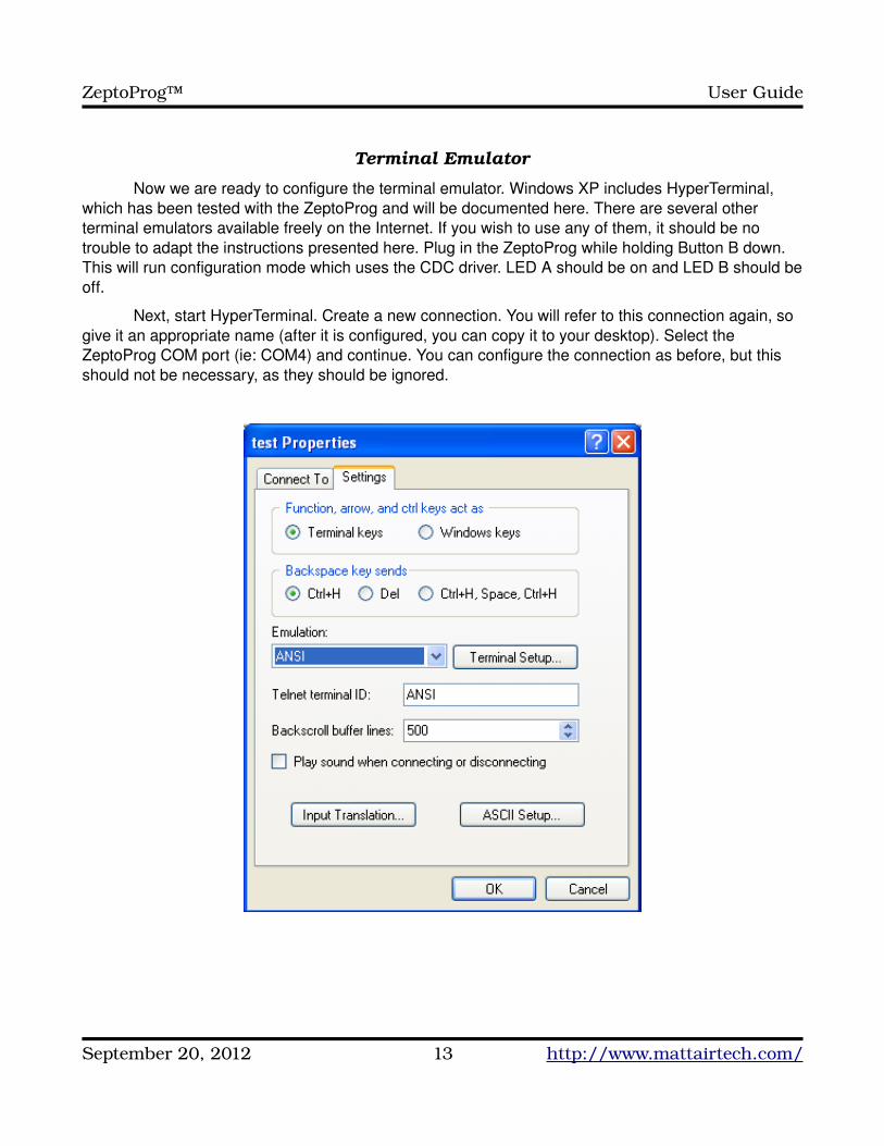
Next, start HyperTerminal. Create a new connection. You will refer to this connection again, so give it an appropriate name (after it is configured, you can copy it to your desktop). Select the ZeptoProg COM port (ie: COM4) and continue. You can configure the connection as before, but this should not be necessary, as they should be ignored.
September 20, 2012 13 http://www.mattairtech.com/

ZeptoProg™ User Guide
After connecting, you may see garbage on the terminal screen. If this is the case, click on the configuration icon and change the emulation to ANSI (or ANSIW). The configuration mode requires an ANSI terminal to allow drawing of the menu system. Normally, when first entering a mode that uses the CDC driver, a message that reads “Press any Key” is printed periodically. If you do not see this message, then too much time has passed between first printing the message and the user connecting the terminal emulator. In this case, the screen may be blank. Just press any key to continue. Note that it may not be possible to switch between modes using the buttons until a key is pressed. Also note that when Terminal Mode is disabled, the “Press any Key” message does not appear, and no key needs to be pressed for the selected application to be ready.
It is important to always click the disconnect icon before switching to the AVR Programmer from configuration mode or application mode. Then click the connect icon a couple seconds after returning. This is required because changing to the AVRISPmkII driver unloads the CDC driver, then loads the AVRISPmkII driver. In order for the terminal to use the same COM port as before, it must be disconnected when returning to the CDC driver so that it does not assign a new COM port. A future firmware release may include the ability to have both drivers loaded simultaneously.
Linux InstallationLinux InstallationLinux is supported as well. You must download and build the toolchain from the latest script
available at AVR Freaks on the AVR GCC Forum (Script for building AVR GCC sticky at http://www.avrfreaks.net/index.php?name=PNphpBB2&file=viewtopic&t=42631). All firmware written for the ZeptoProg is developed under Linux using this toolchain.
Drivers
TODO (drivers should already be installed)
GCC Toolchain
TODO (see opening paragraph)
AVRDUDE
TODO (ie: avrdude p x128a1 c avrisp2 P usb U flash:w:"myfirmware.hex")
dfuprogrammer
TODO (must use version 0.5.2 (currently available via SVN only) or higher)
Terminal Emulator
TODO (can use minicom, config port (ie: /dev/tty/ACM0), save config, run with minicom o)
September 20, 2012 14 http://www.mattairtech.com/
ZeptoProg™ User Guide
ZeptoProg HardwareZeptoProg Hardware
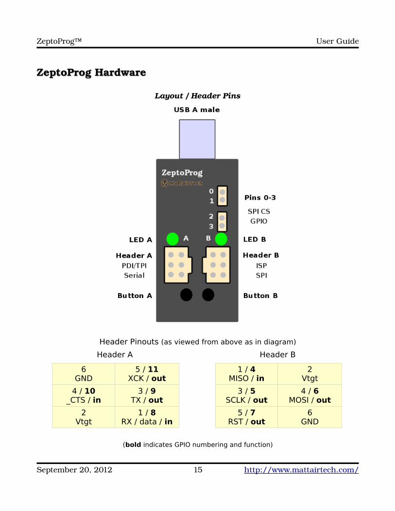
Layout / Header Pins
Header Pinouts (as viewed from above as in diagram)
Header A
6GND
5 / 11XCK / out
4 / 10_CTS / in
3 / 9TX / out
2Vtgt
1 / 8RX / data / in
Header B
1 / 4MISO / in
2Vtgt
3 / 5SCLK / out
4 / 6MOSI / out
5 / 7RST / out
6GND
(bold indicates GPIO numbering and function)
September 20, 2012 15 http://www.mattairtech.com/
ZeptoProg™ User Guide
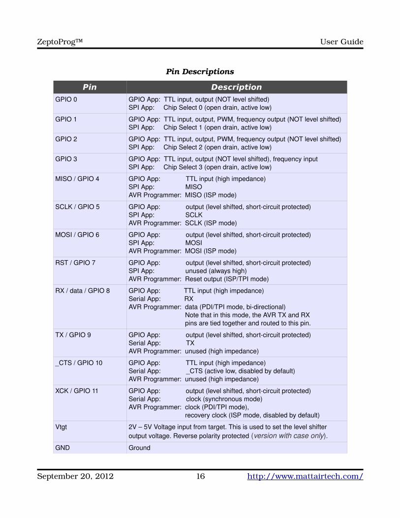
Pin Descriptions
Pin Description
GPIO 0 GPIO App: TTL input, output (NOT level shifted)SPI App: Chip Select 0 (open drain, active low)
GPIO 1 GPIO App: TTL input, output, PWM, frequency output (NOT level shifted)SPI App: Chip Select 1 (open drain, active low)
GPIO 2 GPIO App: TTL input, output, PWM, frequency output (NOT level shifted)SPI App: Chip Select 2 (open drain, active low)
GPIO 3 GPIO App: TTL input, output (NOT level shifted), frequency inputSPI App: Chip Select 3 (open drain, active low)
MISO / GPIO 4 GPIO App: TTL input (high impedance)SPI App: MISOAVR Programmer: MISO (ISP mode)
SCLK / GPIO 5 GPIO App: output (level shifted, shortcircuit protected)SPI App: SCLKAVR Programmer: SCLK (ISP mode)
MOSI / GPIO 6 GPIO App: output (level shifted, shortcircuit protected)SPI App: MOSIAVR Programmer: MOSI (ISP mode)
RST / GPIO 7 GPIO App: output (level shifted, shortcircuit protected)SPI App: unused (always high)AVR Programmer: Reset output (ISP/TPI mode)
RX / data / GPIO 8 GPIO App: TTL input (high impedance)Serial App: RXAVR Programmer: data (PDI/TPI mode, bidirectional) Note that in this mode, the AVR TX and RX pins are tied together and routed to this pin.
TX / GPIO 9 GPIO App: output (level shifted, shortcircuit protected)Serial App: TXAVR Programmer: unused (high impedance)
_CTS / GPIO 10 GPIO App: TTL input (high impedance)Serial App: _CTS (active low, disabled by default)AVR Programmer: unused (high impedance)
XCK / GPIO 11 GPIO App: output (level shifted, shortcircuit protected)Serial App: clock (synchronous mode)AVR Programmer: clock (PDI/TPI mode), recovery clock (ISP mode, disabled by default)
Vtgt 2V – 5V Voltage input from target. This is used to set the level shifter output voltage. Reverse polarity protected (version with case only).
GND Ground
September 20, 2012 16 http://www.mattairtech.com/
ZeptoProg™ User Guide
Buttons
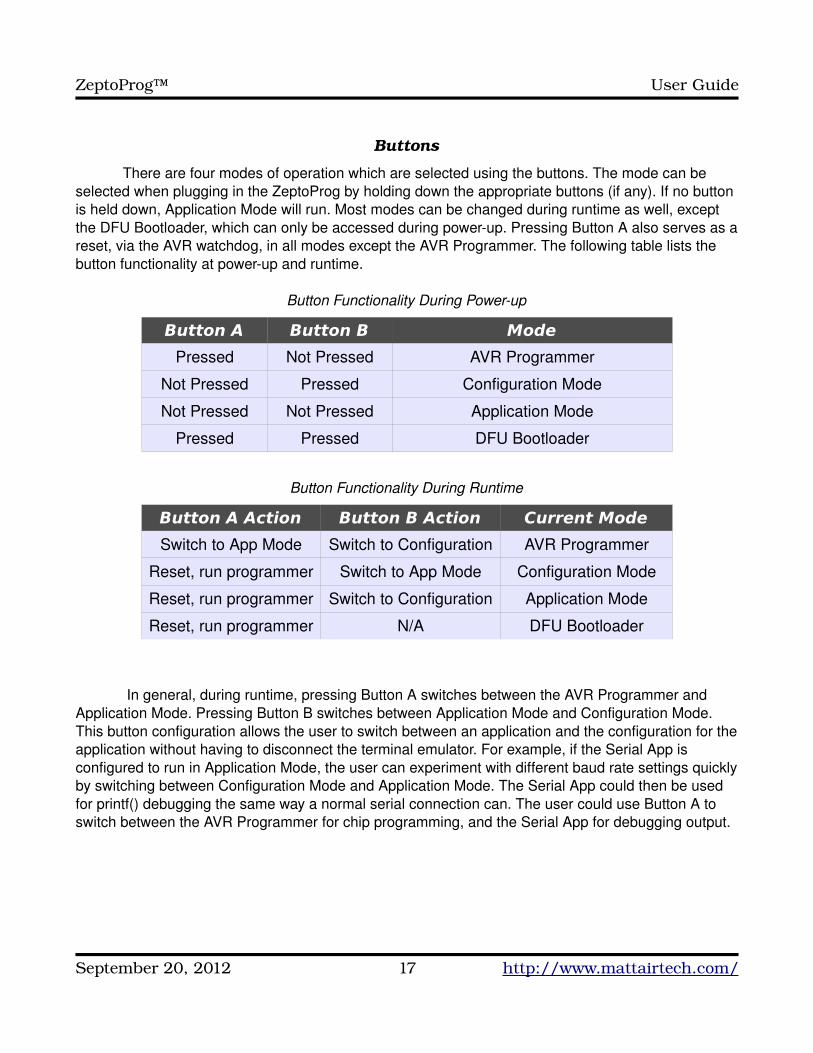
There are four modes of operation which are selected using the buttons. The mode can be selected when plugging in the ZeptoProg by holding down the appropriate buttons (if any). If no button is held down, Application Mode will run. Most modes can be changed during runtime as well, except the DFU Bootloader, which can only be accessed during powerup. Pressing Button A also serves as a reset, via the AVR watchdog, in all modes except the AVR Programmer. The following table lists the button functionality at powerup and runtime.
Button Functionality During Powerup
Button A Button B Mode
Pressed Not Pressed AVR Programmer
Not Pressed Pressed Configuration Mode
Not Pressed Not Pressed Application Mode
Pressed Pressed DFU Bootloader
Button Functionality During Runtime
Button A Action Button B Action Current Mode
Switch to App Mode Switch to Configuration AVR Programmer
Reset, run programmer Switch to App Mode Configuration Mode
Reset, run programmer Switch to Configuration Application Mode
Reset, run programmer N/A DFU Bootloader
In general, during runtime, pressing Button A switches between the AVR Programmer and Application Mode. Pressing Button B switches between Application Mode and Configuration Mode. This button configuration allows the user to switch between an application and the configuration for the application without having to disconnect the terminal emulator. For example, if the Serial App is configured to run in Application Mode, the user can experiment with different baud rate settings quickly by switching between Configuration Mode and Application Mode. The Serial App could then be used for printf() debugging the same way a normal serial connection can. The user could use Button A to switch between the AVR Programmer for chip programming, and the Serial App for debugging output.
September 20, 2012 17 http://www.mattairtech.com/
ZeptoProg™ User Guide
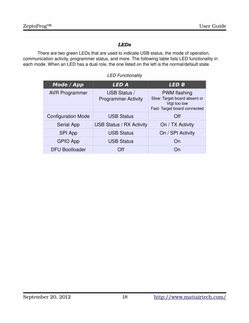
LEDs
There are two green LEDs that are used to indicate USB status, the mode of operation, communication activity, programmer status, and more. The following table lists LED functionality in each mode. When an LED has a dual role, the one listed on the left is the normal/default state.
LED Functionality
Mode / App LED A LED B
AVR Programmer USB Status / Programmer Activity
PWM flashingSlow: Target board absent or
Vtgt too lowFast: Target board connected
Configuration Mode USB Status Off
Serial App USB Status / RX Activity On / TX Activity
SPI App USB Status On / SPI Activity
GPIO App USB Status On
DFU Bootloader Off On
September 20, 2012 18 http://www.mattairtech.com/
ZeptoProg™ User Guide
ConfigurationConfigurationThe ZeptoProg AVR Programmer and Application Mode can be configured by entering
Configuration Mode. This configuration is stored in nonvolatile EEPROM memory. Configuration mode requires an ANSI terminal emulator. Configuration options are highlighted by using the up and down arrow keys, and selected using the enter key. Some dialogs are for entering numbers in hexadecimal. Here, the left arrow key, right arrow key, and backspace can be used. The following lists the structure of the menu system:
● Select App (select which application will run when in Application Mode)
● Serial App
● SPI App
● GPIO App
● Terminal Mode (select between Terminal Mode and NonInteractive Mode)
● Disabled (NonInteractive Mode, intended for use by user code, scripts)
● Enabled (Terminal Mode, intended for terminal emulators)
● Config Serial
● (see Serial App section for configuration options)
● Config SPI
● (see SPI App section for configuration options)
● Config AVRISPmkII
● (see AVR Programmer section for configuration options)
● Credits (displays list of firmware authors)
When entering Application Mode, the App selected under “Select App” will run. To switch to another App, the user must switch to Application Mode, change the selected App, then switch back to Application Mode. All outputs are tristated when in Configuration Mode, and no inputs are active. This is a good time to make connection changes, if necessary.
Terminal Mode allows the ZeptoProg to use a terminal emulator. This mode affects the GPIO App and SPI App. In general, enabling Terminal Mode causes a “Press any key” prompt to appear upon entering any mode that uses the virtual COM port (this is done only once per reset), causes a prompt to appear, echoes sent characters, outputs carriage return and newline to the terminal upon pressing enter, and outputs error messages as text strings rather than single byte codes. Additionally, the behavior of the SPI commands changes. NonInteractive Mode is when Terminal Mode is set to disabled. This mode is useful to interface with user code on the PC, like a script or program.
September 20, 2012 19 http://www.mattairtech.com/
ZeptoProg™ User Guide
AVR ProgrammerAVR ProgrammerThe ZeptoProg AVR Programmer is based on the AVRISPmkII compatible programmer written
by Dean Camera (http://www.fourwalledcubicle.com/). It supports programming of all Atmel AVR microcontrollers with an ISP, PDI, or TPI programming interface. These include the megaAVR series (ISP), the tinyAVR series (ISP, TPI), the XMEGA series (PDI), the USB AVRs (ISP), and the listed CAN and PWM AVRs (see Appendix B for device listing). The ZeptoProg uses the standard header pinouts for both ISP and PDI. TPI does not use the standard pinout, however, singlepin jumper cables can be used. At the time of this writing, only 6pin devices use TPI.
Programming speeds up to 8MHz are supported in ISP mode. However, current AVRs require a programming speed less than ¼ of the target clock speed. For 20MHz AVRs, this is 4MHz. For 16MHz, 2MHz is the limit. It is not recommended to operate at exactly ¼ of the target frequency, especially when programming fuses, as this can cause them to become incorrectly set and possibly render the AVR useless (unless parallel programming is available). Note that many AVRs come from the factory with the clock source set to the internal 8MHz oscillator and with the CKDIV8 fuse programmed, resulting in a clock speed of 1MHz. In these cases, the ISP programming speed should be set to 125KHz or less until CKDIV8 is unprogrammed and power cycled.
For ISP mode, a 1MHz recovery clock can be enabled. This clock can be connected to the target clock input. This is useful, for example, to allow resetting of fuses that were misconfigured to use an external clock when intending to use a crystal or internal oscillator. This recovery clock should only be used with an ISP programming speed of 125KHz.
The ZeptoProg supports target devices operating at 2V to 5V. Outputs from the ZeptoProg are levelshifted down to the target voltage. The target device supplies this voltage via the Vtgt input. This input is reversepolarity protected by a FET to ensure a low voltage drop. The outputs have series resistors that limit current to around 25mA.
Configuration● PC Program (Under Windows, this must be set to the program used with the AVR Programmer)
● AVR Studio
● AVRDUDE
● Recovery Clock (If enabled, in ISP mode a 1MHz clock will be output on XCK pin of header A)
● Disabled
● Enabled
Connecting Target Board
Always ensure that the ZeptoProg is powered before connecting the target board. In all three modes, the Vtgt pin is used as an input to the ZeptoProg that determines the output high voltage. This must be supplied by the target board. It is possible to output 5V from USB to the target board, thus powering the target board. Care must be taken when doing this. Consult Appendix A for more
September 20, 2012 20 http://www.mattairtech.com/
ZeptoProg™ User Guide
information.
● ISP mode uses the standard pinout, and is available on header B. If enabled, a 1MHz recovery clock will be output on the XCK pin of header A.
● PDI mode also uses the standard pinout, and is available on header A. During PDI programming, the ZeptoProg USART TX and RX lines are internally tied together and connected to the RX/data pin. In this configuration, the pin is called data and is bidirectional. The TX pin will then be tristated. Since _CTS is unused by the programmer, it is also tristated.
● TPI uses a nonstandard pinout. TPI uses the same signals as PDI but with the addition of Reset. The Reset output is available from RST on header B. Data and XCK are taken from header A. During TPI programming, the ZeptoProg USART TX and RX lines are internally tied together and connected to the RX/data pin. In this configuration, the pin is called data and is bidirectional. The TX pin will then be tristated. Since _CTS is unused by the programmer, it is also tristated.
Using AVR Studio
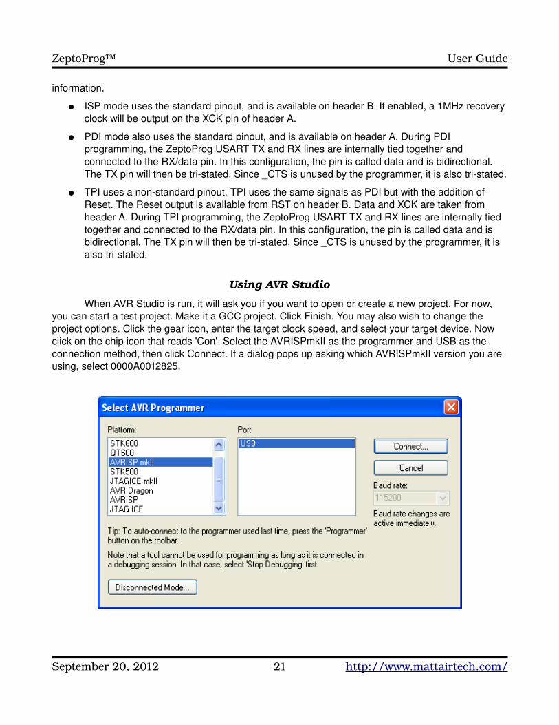
When AVR Studio is run, it will ask you if you want to open or create a new project. For now, you can start a test project. Make it a GCC project. Click Finish. You may also wish to change the project options. Click the gear icon, enter the target clock speed, and select your target device. Now click on the chip icon that reads 'Con'. Select the AVRISPmkII as the programmer and USB as the connection method, then click Connect. If a dialog pops up asking which AVRISPmkII version you are using, select 0000A0012825.
September 20, 2012 21 http://www.mattairtech.com/
ZeptoProg™ User Guide
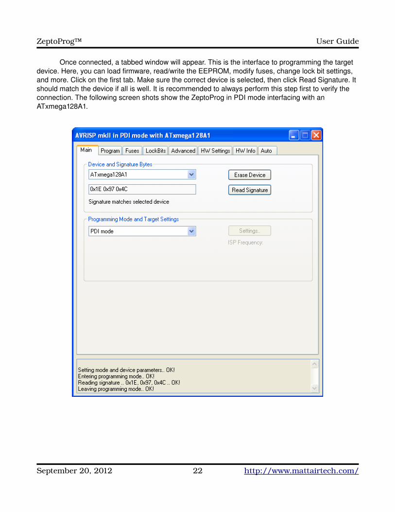
Once connected, a tabbed window will appear. This is the interface to programming the target device. Here, you can load firmware, read/write the EEPROM, modify fuses, change lock bit settings, and more. Click on the first tab. Make sure the correct device is selected, then click Read Signature. It should match the device if all is well. It is recommended to always perform this step first to verify the connection. The following screen shots show the ZeptoProg in PDI mode interfacing with an ATxmega128A1.
September 20, 2012 22 http://www.mattairtech.com/
ZeptoProg™ User Guide
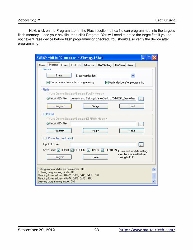
Next, click on the Program tab. In the Flash section, a hex file can programmed into the target's flash memory. Load your hex file, then click Program. You will need to erase the target first if you do not have “Erase device before flash programming” checked. You should also verify the device after programming.
September 20, 2012 23 http://www.mattairtech.com/
ZeptoProg™ User Guide
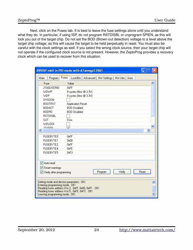
Next, click on the Fuses tab. It is best to leave the fuse settings alone until you understand what they do. In particular, if using ISP, do not program RSTDISBL or unprogram SPIEN, as this will lock you out of the target chip. Do not set the BOD (Brownout detection) voltage to a level above the target chip voltage, as this will cause the target to be held perpetually in reset. You must also be careful with the clock settings as well. If you select the wrong clock source, then your target chip will not operate if the configured clock source is not present. However, the ZeptoProg provides a recovery clock which can be used to recover from this situation.
September 20, 2012 24 http://www.mattairtech.com/
ZeptoProg™ User Guide
Now you may wish to look at the other tabs. Note that on the HW Settings tab, the reported voltage will always be 5V, regardless of the actual voltage present on Vtgt. The Firmware upgrade feature on the same tab should not be used. This is also true for the AVRISPmkII upgrade feature in the AVR Studio tools menu, or any upgrade pop up windows. The ZeptoProg AVR Programmer is not an actual AVRISPmkII, it just emulates one, so you should not attempt to update the ZeptoProg firmware using AVR Studio. Any firmware updates will be posted to the website and loaded using FLIP or dfuprogrammer.
Using AVRDUDE
TODO (ie: avrdude p x128a1 c avrisp2 P usb U flash:w:"myfirmware.hex")
September 20, 2012 25 http://www.mattairtech.com/
ZeptoProg™ User Guide
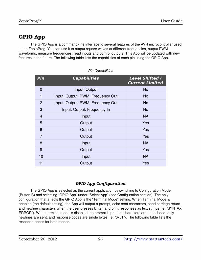
GPIO AppGPIO AppThe GPIO App is a commandline interface to several features of the AVR microcontroller used
in the ZeptoProg. You can use it to output square waves at different frequencies, output PWM waveforms, measure frequencies, read inputs and control outputs. This App will be updated with new features in the future. The following table lists the capabilities of each pin using the GPIO App.
Pin Capabilities
Pin Capabilities Level Shifted / Current Limited
0 Input, Output No
1 Input, Output, PWM, Frequency Out No
2 Input, Output, PWM, Frequency Out No
3 Input, Output, Frequency In No
4 Input NA
5 Output Yes
6 Output Yes
7 Output Yes
8 Input NA
9 Output Yes
10 Input NA
11 Output Yes
GPIO App Configuration
The GPIO App is selected as the current application by switching to Configuration Mode (Button B) and selecting “GPIO App” under “Select App” (see Configuration section). The only configuration that affects the GPIO App is the “Terminal Mode” setting. When Terminal Mode is enabled (the default setting), the App will output a prompt, echo sent characters, send carriage return and newline characters when the user presses Enter, and print responses as text strings (ie: “SYNTAX ERROR”). When terminal mode is disabled, no prompt is printed, characters are not echoed, only newlines are sent, and response codes are single bytes (ie: “0x01”). The following table lists the response codes for both modes.
September 20, 2012 26 http://www.mattairtech.com/
ZeptoProg™ User Guide
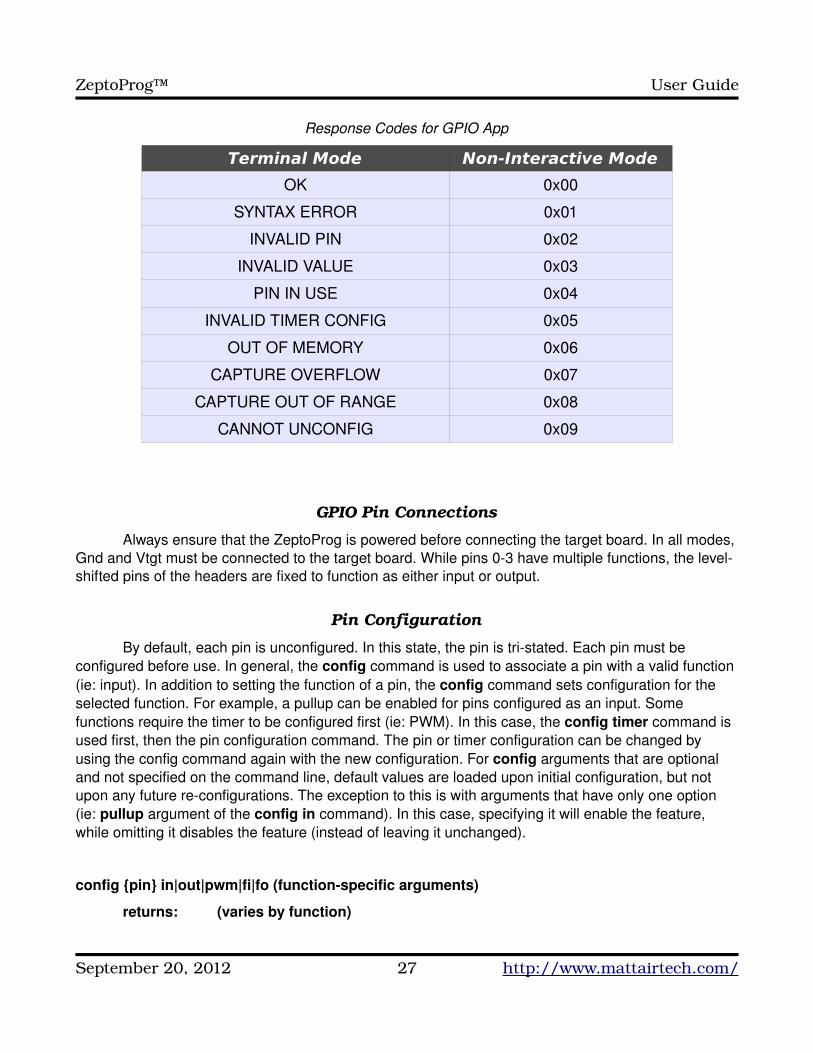
Response Codes for GPIO App
Terminal Mode Non-Interactive Mode
OK 0x00
SYNTAX ERROR 0x01
INVALID PIN 0x02
INVALID VALUE 0x03
PIN IN USE 0x04
INVALID TIMER CONFIG 0x05
OUT OF MEMORY 0x06
CAPTURE OVERFLOW 0x07
CAPTURE OUT OF RANGE 0x08
CANNOT UNCONFIG 0x09
GPIO Pin Connections
Always ensure that the ZeptoProg is powered before connecting the target board. In all modes, Gnd and Vtgt must be connected to the target board. While pins 03 have multiple functions, the levelshifted pins of the headers are fixed to function as either input or output.
Pin Configuration
By default, each pin is unconfigured. In this state, the pin is tristated. Each pin must be configured before use. In general, the config command is used to associate a pin with a valid function (ie: input). In addition to setting the function of a pin, the config command sets configuration for the selected function. For example, a pullup can be enabled for pins configured as an input. Some functions require the timer to be configured first (ie: PWM). In this case, the config timer command is used first, then the pin configuration command. The pin or timer configuration can be changed by using the config command again with the new configuration. For config arguments that are optional and not specified on the command line, default values are loaded upon initial configuration, but not upon any future reconfigurations. The exception to this is with arguments that have only one option (ie: pullup argument of the config in command). In this case, specifying it will enable the feature, while omitting it disables the feature (instead of leaving it unchanged).
config {pin} in|out|pwm|fi|fo (functionspecific arguments)
returns: (varies by function)
September 20, 2012 27 http://www.mattairtech.com/
ZeptoProg™ User Guide
example: config 3 in pullup
{pin}: Required argument indicating the pin number to assign. Can be 011.
in|out|pwm|fi|fo: Required argument specifying the function the pin is to be assigned to. in stands for input, out stands for output, pwm stands for pulse width modulation, fi stands for frequency input, and fo stands for frequency output.
(functionspecific arguments): Arguments specific to each function, which may include required arguments, should be placed here.
If a pin must be changed to a different function (ie: from input to output), then it must be disassociated with the current function by using the “unconfig” command first. Likewise, if the timer is switched to a different function (ie: PWM to frequency output) and a pin is currently associated with the function, then the pin(s) must be unconfigured first.
unconfig {pin}
returns: OK | SYNTAX ERROR | INVALID PIN | CANNOT UNCONFIG
example: unconfig 3
{pin}: Required argument indicating the pin number to unassign. Can be 011.
Timer Configuration
The timer must be configured for the PWM, frequency output, and frequency input functions. The config timer command configures the timer for the specified function. The prescaler setting (ie: div1) affects all three functions, while the rest of the settings are used only by the PWM function.
config timer [off|pwm|fo|fi] [div1|div8|div64|div256|div1024] [fast|phase|freq] [top {value (16b)}]
returns: OK | SYNTAX ERROR | INVALID VALUE | PIN IN USE
example: config timer pwm fast top 0x7fff
[off|pwm|fo|fi]: Optional argument that specifies the function the timer will be used for (default off). fo stands for frequency output and fi for frequency input.
[fast|phase|freq]: Optional argument that specifies what mode the PWM function will run in (default fast). These correspond to the PWM modes of the underlying AVR microcontroller. Please consult the Atmega32U2 datasheet for more information. phase stands for phase correct and freq stands for phase and frequency correct. This setting is ignored when selecting a nonPWM function.
September 20, 2012 28 http://www.mattairtech.com/
ZeptoProg™ User Guide
[div1|div8|div64|div256|div1024]: Optional argument that specifies the timer prescaler setting (default div1). This is the divider of the 16MHz clock frequency. The timer will “tick” at this divided frequency. Please consult the Atmega32U2 datasheet for more information.
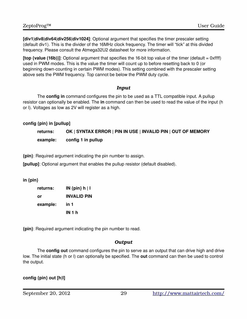
[top {value (16b)}]: Optional argument that specifies the 16bit top value of the timer (default = 0xffff) used in PWM modes. This is the value the timer will count up to before resetting back to 0 (or beginning downcounting in certain PWM modes). This setting combined with the prescaler setting above sets the PWM frequency. Top cannot be below the PWM duty cycle.
Input
The config in command configures the pin to be used as a TTL compatible input. A pullup resistor can optionally be enabled. The in command can then be used to read the value of the input (h or l). Voltages as low as 2V will register as a high.
config {pin} in [pullup]
returns: OK | SYNTAX ERROR | PIN IN USE | INVALID PIN | OUT OF MEMORY
example: config 1 in pullup
{pin}: Required argument indicating the pin number to assign.
[pullup]: Optional argument that enables the pullup resistor (default disabled).
in {pin}
returns: IN {pin} h | l
or INVALID PIN
example: in 1
IN 1 h
{pin}: Required argument indicating the pin number to read.
Output
The config out command configures the pin to serve as an output that can drive high and drive low. The initial state (h or l) can optionally be specified. The out command can then be used to control the output.
config {pin} out [h|l]
September 20, 2012 29 http://www.mattairtech.com/
ZeptoProg™ User Guide
returns: OK | SYNTAX ERROR | PIN IN USE | INVALID PIN | OUT OF MEMORY
example: config 1 out
{pin}: Required argument indicating the pin number to assign.
[h|l]: Optional argument specifying the initial state (default high).
out {pin} h|l
returns: OK | SYNTAX ERROR | INVALID PIN
example: out 1 h
{pin}: Required argument indicating the pin number to control.
h|l: Required argument specifying the output state.
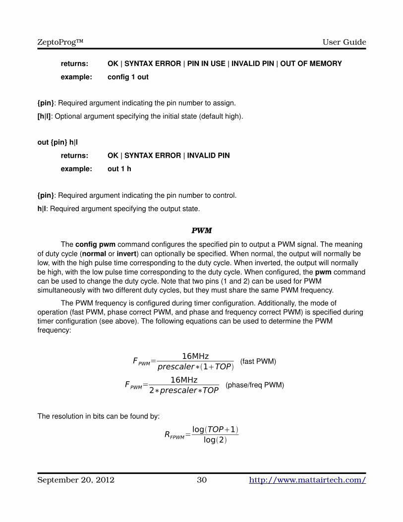
PWM
The config pwm command configures the specified pin to output a PWM signal. The meaning of duty cycle (normal or invert) can optionally be specified. When normal, the output will normally be low, with the high pulse time corresponding to the duty cycle. When inverted, the output will normally be high, with the low pulse time corresponding to the duty cycle. When configured, the pwm command can be used to change the duty cycle. Note that two pins (1 and 2) can be used for PWM simultaneously with two different duty cycles, but they must share the same PWM frequency.
The PWM frequency is configured during timer configuration. Additionally, the mode of operation (fast PWM, phase correct PWM, and phase and frequency correct PWM) is specified during timer configuration (see above). The following equations can be used to determine the PWM frequency:
F PWM=16MHz
prescaler∗1TOP(fast PWM)
FPWM=16MHz
2∗prescaler∗TOP(phase/freq PWM)
The resolution in bits can be found by:
RFPWM=logTOP1
log2
September 20, 2012 30 http://www.mattairtech.com/
ZeptoProg™ User Guide
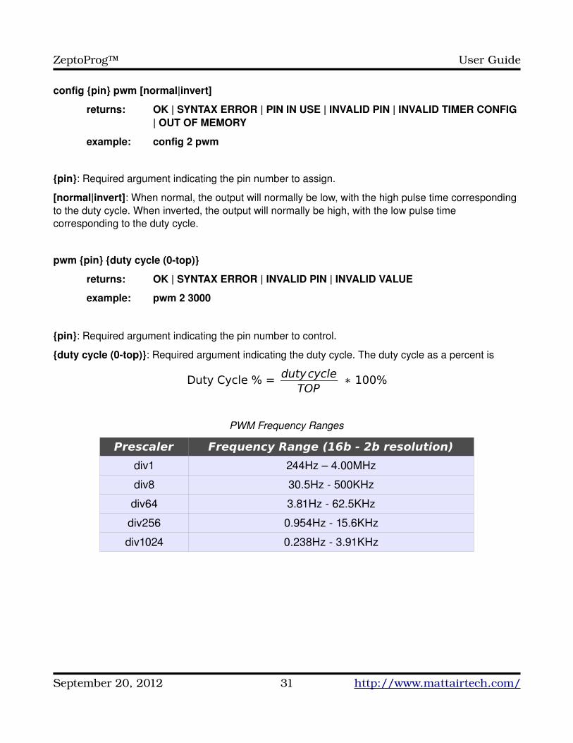
config {pin} pwm [normal|invert]
returns: OK | SYNTAX ERROR | PIN IN USE | INVALID PIN | INVALID TIMER CONFIG | OUT OF MEMORY
example: config 2 pwm
{pin}: Required argument indicating the pin number to assign.
[normal|invert]: When normal, the output will normally be low, with the high pulse time corresponding to the duty cycle. When inverted, the output will normally be high, with the low pulse time corresponding to the duty cycle.
pwm {pin} {duty cycle (0top)}
returns: OK | SYNTAX ERROR | INVALID PIN | INVALID VALUE
example: pwm 2 3000
{pin}: Required argument indicating the pin number to control.
{duty cycle (0top)}: Required argument indicating the duty cycle. The duty cycle as a percent is
Duty Cycle % = dutycycleTOP
∗ 100%
PWM Frequency Ranges
Prescaler Frequency Range (16b - 2b resolution)
div1 244Hz – 4.00MHz
div8 30.5Hz 500KHz
div64 3.81Hz 62.5KHz
div256 0.954Hz 15.6KHz
div1024 0.238Hz 3.91KHz
September 20, 2012 31 http://www.mattairtech.com/
ZeptoProg™ User Guide
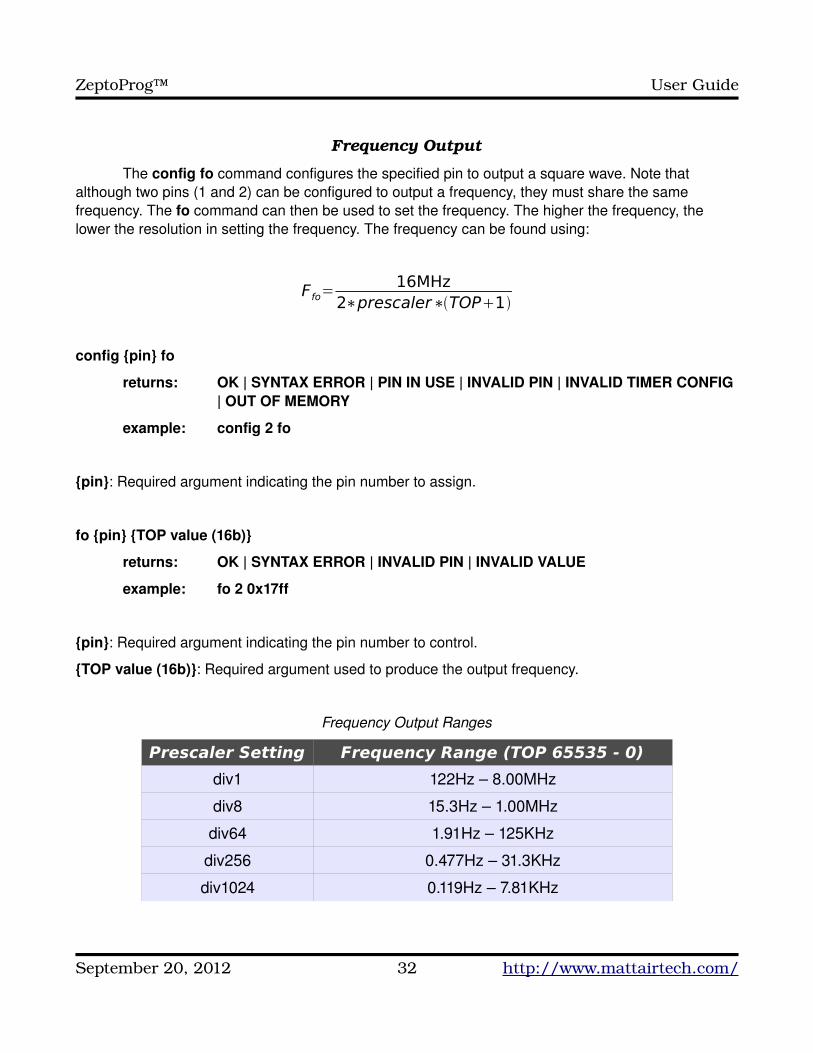
Frequency Output
The config fo command configures the specified pin to output a square wave. Note that although two pins (1 and 2) can be configured to output a frequency, they must share the same frequency. The fo command can then be used to set the frequency. The higher the frequency, the lower the resolution in setting the frequency. The frequency can be found using:
Ffo=16MHz
2∗prescaler∗TOP1
config {pin} fo
returns: OK | SYNTAX ERROR | PIN IN USE | INVALID PIN | INVALID TIMER CONFIG | OUT OF MEMORY
example: config 2 fo
{pin}: Required argument indicating the pin number to assign.
fo {pin} {TOP value (16b)}
returns: OK | SYNTAX ERROR | INVALID PIN | INVALID VALUE
example: fo 2 0x17ff
{pin}: Required argument indicating the pin number to control.
{TOP value (16b)}: Required argument used to produce the output frequency.
Frequency Output Ranges
Prescaler Setting Frequency Range (TOP 65535 - 0)
div1 122Hz – 8.00MHz
div8 15.3Hz – 1.00MHz
div64 1.91Hz – 125KHz
div256 0.477Hz – 31.3KHz
div1024 0.119Hz – 7.81KHz
September 20, 2012 32 http://www.mattairtech.com/
ZeptoProg™ User Guide
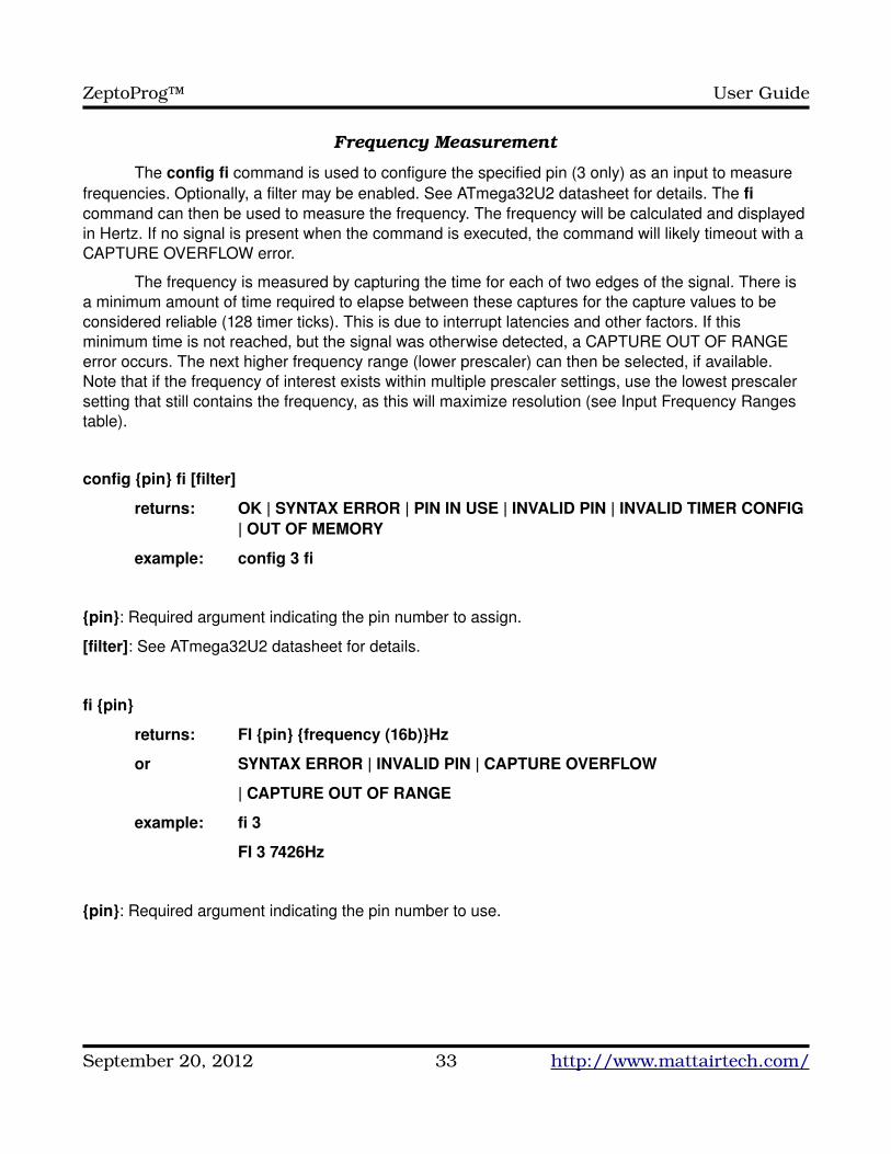
Frequency Measurement
The config fi command is used to configure the specified pin (3 only) as an input to measure frequencies. Optionally, a filter may be enabled. See ATmega32U2 datasheet for details. The fi command can then be used to measure the frequency. The frequency will be calculated and displayed in Hertz. If no signal is present when the command is executed, the command will likely timeout with a CAPTURE OVERFLOW error.
The frequency is measured by capturing the time for each of two edges of the signal. There is a minimum amount of time required to elapse between these captures for the capture values to be considered reliable (128 timer ticks). This is due to interrupt latencies and other factors. If this minimum time is not reached, but the signal was otherwise detected, a CAPTURE OUT OF RANGE error occurs. The next higher frequency range (lower prescaler) can then be selected, if available. Note that if the frequency of interest exists within multiple prescaler settings, use the lowest prescaler setting that still contains the frequency, as this will maximize resolution (see Input Frequency Ranges table).
config {pin} fi [filter]
returns: OK | SYNTAX ERROR | PIN IN USE | INVALID PIN | INVALID TIMER CONFIG | OUT OF MEMORY
example: config 3 fi
{pin}: Required argument indicating the pin number to assign.
[filter]: See ATmega32U2 datasheet for details.
fi {pin}
returns: FI {pin} {frequency (16b)}Hz
or SYNTAX ERROR | INVALID PIN | CAPTURE OVERFLOW
| CAPTURE OUT OF RANGE
example: fi 3
FI 3 7426Hz
{pin}: Required argument indicating the pin number to use.
September 20, 2012 33 http://www.mattairtech.com/
ZeptoProg™ User Guide
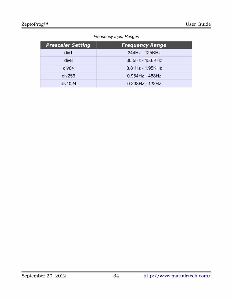
Frequency Input Ranges
Prescaler Setting Frequency Range
div1 244Hz 125KHz
div8 30.5Hz 15.6KHz
div64 3.81Hz 1.95KHz
div256 0.954Hz 488Hz
div1024 0.238Hz 122Hz
September 20, 2012 34 http://www.mattairtech.com/
ZeptoProg™ User Guide
Serial AppSerial AppThe Serial App is a USB to serial bridge that allows the target MCU (or other device) to
communicate with a PC application (like a terminal) over USB. On the PC side, the ZeptoProg will appear as a virtual COM port. Unlike the SPI App and GPIO App, there is no terminal mode or commands. The ZeptoProg simply relays bytes between the PC and target.
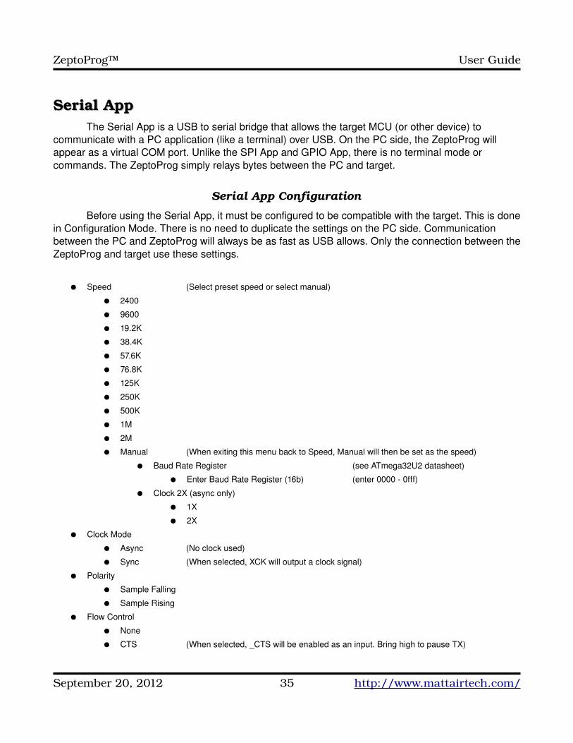
Serial App Configuration
Before using the Serial App, it must be configured to be compatible with the target. This is done in Configuration Mode. There is no need to duplicate the settings on the PC side. Communication between the PC and ZeptoProg will always be as fast as USB allows. Only the connection between the ZeptoProg and target use these settings.
● Speed (Select preset speed or select manual)
● 2400
● 9600
● 19.2K
● 38.4K
● 57.6K
● 76.8K
● 125K
● 250K
● 500K
● 1M
● 2M
● Manual (When exiting this menu back to Speed, Manual will then be set as the speed)
● Baud Rate Register (see ATmega32U2 datasheet)
● Enter Baud Rate Register (16b) (enter 0000 0fff)
● Clock 2X (async only)
● 1X
● 2X
● Clock Mode
● Async (No clock used)
● Sync (When selected, XCK will output a clock signal)
● Polarity
● Sample Falling
● Sample Rising
● Flow Control
● None
● CTS (When selected, _CTS will be enabled as an input. Bring high to pause TX)
September 20, 2012 35 http://www.mattairtech.com/
ZeptoProg™ User Guide
● Data Bits
● 5
● 6
● 7
● 8
● Stop Bits
● 1
● 2
● Parity
● None
● Even
● Odd
Serial Connections
The ZeptoProg should be powered before the target board. In all modes, Gnd and Vtgt must be connected to the target board. TX and/or RX must be connected as well. When in synchronous mode, the ZeptoProg is the master, so the XCK pin is enabled as an output. The target board must enable its clock pin as an input and be configured as a slave. If _CTS is used, connect it to the target _RTS line. When _CTS is low, TX activity (from the ZeptoProg to the target) occurs normally. When _CTS is brought high, TX pauses. This prevents buffer overflows on the target if it becomes busy.
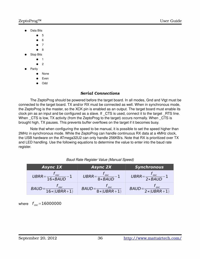
Note that when configuring the speed to be manual, it is possible to set the speed higher than 2MHz in synchronous mode. While the ZeptoProg can handle continuous RX data at a 4MHz clock, the USB hardware on the ATmega32U2 can only handle 256KB/s. Note that RX is prioritized over TX and LED handling. Use the following equations to determine the value to enter into the baud rate register.
Baud Rate Register Value (Manual Speed)
Async 1X Async 2X Synchronous
UBRR=f osc
16∗BAUD−1 UBRR=
f osc8∗BAUD
−1 UBRR=f osc
2∗BAUD−1
BAUD=f osc
16∗UBRR1BAUD=
f osc8∗UBRR1
BAUD=f osc
2∗UBRR1
where f osc=16000000
September 20, 2012 36 http://www.mattairtech.com/
ZeptoProg™ User Guide
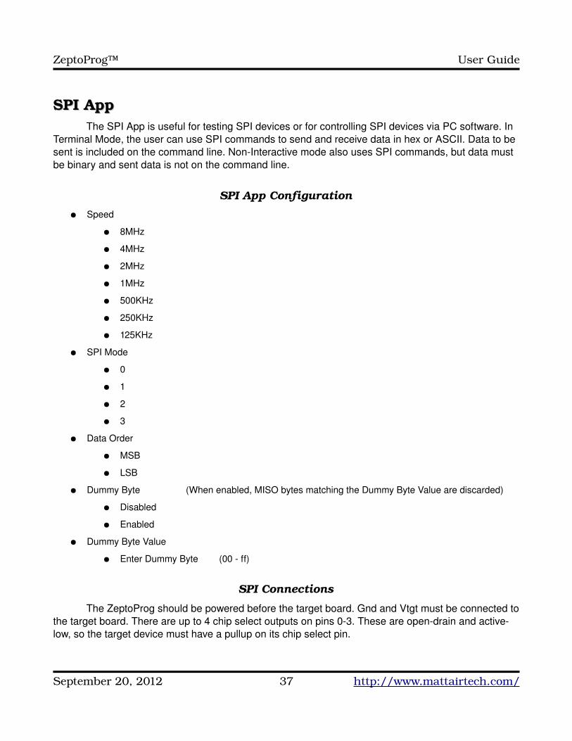
SPI AppSPI AppThe SPI App is useful for testing SPI devices or for controlling SPI devices via PC software. In
Terminal Mode, the user can use SPI commands to send and receive data in hex or ASCII. Data to be sent is included on the command line. NonInteractive mode also uses SPI commands, but data must be binary and sent data is not on the command line.
SPI App Configuration● Speed
● 8MHz
● 4MHz
● 2MHz
● 1MHz
● 500KHz
● 250KHz
● 125KHz
● SPI Mode
● 0
● 1
● 2
● 3
● Data Order
● MSB
● LSB
● Dummy Byte (When enabled, MISO bytes matching the Dummy Byte Value are discarded)
● Disabled
● Enabled
● Dummy Byte Value
● Enter Dummy Byte (00 ff)
SPI Connections
The ZeptoProg should be powered before the target board. Gnd and Vtgt must be connected to the target board. There are up to 4 chip select outputs on pins 03. These are opendrain and activelow, so the target device must have a pullup on its chip select pin.
September 20, 2012 37 http://www.mattairtech.com/
ZeptoProg™ User Guide
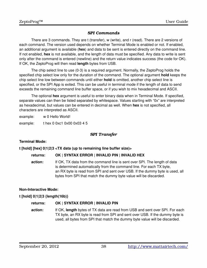
SPI Commands
There are 3 commands. They are t (transfer), w (write), and r (read). There are 2 versions of each command. The version used depends on whether Terminal Mode is enabled or not. If enabled, an additional argument is available (hex) and data to be sent is entered directly on the command line. If not enabled, hex is not available, and the length of data must be specified. Any data to write is sent only after the command is entered (newline) and the return value indicates success (the code for OK). If OK, the ZeptoProg will then read length bytes from USB.
The chip select line to use (03) is a required argument. Normally, the ZeptoProg holds the specified chip select low only for the duration of the command. The optional argument hold keeps the chip select line low between commands until either hold is omitted, another chip select line is specified, or the SPI App is exited. This can be useful in terminal mode if the length of data to send exceeds the remaining command line buffer space, or if you wish to mix hexadecimal and ASCII.
The optional hex argument is useful to enter binary data when in Terminal Mode. If specified, separate values can then be listed separated by whitespace. Values starting with “0x” are interpreted as hexadecimal, but values can be entered in decimal as well. When hex is not specified, all characters are interpreted as ASCII.
example: w 0 Hello World!
example: t hex 0 0xc1 0x00 0x03 4 5
SPI Transfer
Terminal Mode:
t [hold] [hex] 0|1|2|3 <TX data (up to remaining line buffer size)>
returns: OK | SYNTAX ERROR | INVALID PIN | INVALID HEX
action: If OK, TX data from the command line is sent over SPI. The length of data is determined automatically from the command line. For each TX byte, an RX byte is read from SPI and sent over USB. If the dummy byte is used, all bytes from SPI that match the dummy byte value will be discarded.
NonInteractive Mode:
t [hold] 0|1|2|3 {length(16b)}
returns: OK | SYNTAX ERROR | INVALID PIN
action: If OK, length bytes of TX data are read from USB and sent over SPI. For each TX byte, an RX byte is read from SPI and sent over USB. If the dummy byte is used, all bytes from SPI that match the dummy byte value will be discarded.
September 20, 2012 38 http://www.mattairtech.com/
ZeptoProg™ User Guide
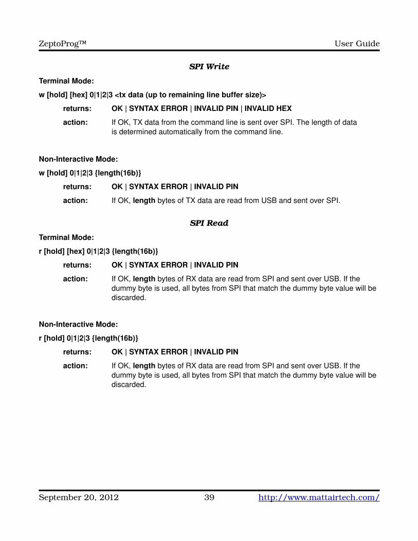
SPI Write
Terminal Mode:
w [hold] [hex] 0|1|2|3 <tx data (up to remaining line buffer size)>
returns: OK | SYNTAX ERROR | INVALID PIN | INVALID HEX
action: If OK, TX data from the command line is sent over SPI. The length of data is determined automatically from the command line.
NonInteractive Mode:
w [hold] 0|1|2|3 {length(16b)}
returns: OK | SYNTAX ERROR | INVALID PIN
action: If OK, length bytes of TX data are read from USB and sent over SPI.
SPI Read
Terminal Mode:
r [hold] [hex] 0|1|2|3 {length(16b)}
returns: OK | SYNTAX ERROR | INVALID PIN
action: If OK, length bytes of RX data are read from SPI and sent over USB. If the dummy byte is used, all bytes from SPI that match the dummy byte value will be discarded.
NonInteractive Mode:
r [hold] 0|1|2|3 {length(16b)}
returns: OK | SYNTAX ERROR | INVALID PIN
action: If OK, length bytes of RX data are read from SPI and sent over USB. If the dummy byte is used, all bytes from SPI that match the dummy byte value will be discarded.
September 20, 2012 39 http://www.mattairtech.com/
ZeptoProg™ User Guide
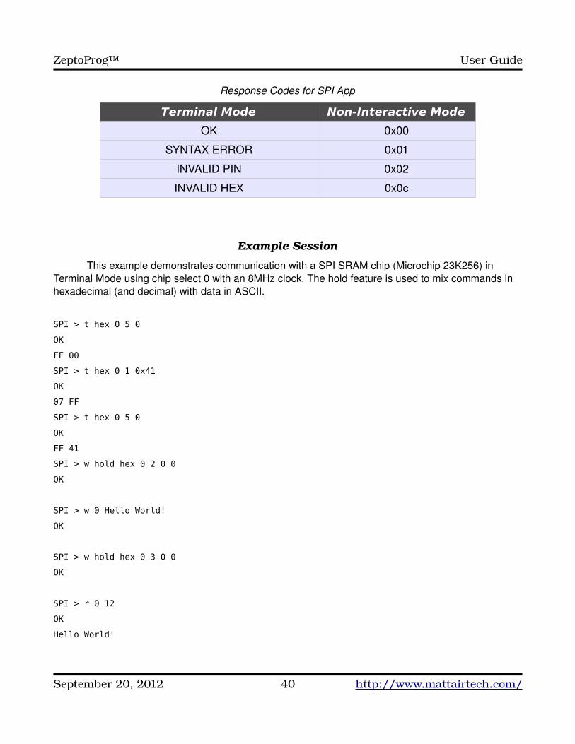
Response Codes for SPI App
Terminal Mode Non-Interactive Mode
OK 0x00
SYNTAX ERROR 0x01
INVALID PIN 0x02
INVALID HEX 0x0c
Example Session
This example demonstrates communication with a SPI SRAM chip (Microchip 23K256) in Terminal Mode using chip select 0 with an 8MHz clock. The hold feature is used to mix commands in hexadecimal (and decimal) with data in ASCII.
SPI > t hex 0 5 0
OK
FF 00
SPI > t hex 0 1 0x41
OK
07 FF
SPI > t hex 0 5 0
OK
FF 41
SPI > w hold hex 0 2 0 0
OK
SPI > w 0 Hello World!
OK
SPI > w hold hex 0 3 0 0
OK
SPI > r 0 12
OK
Hello World!
September 20, 2012 40 http://www.mattairtech.com/
ZeptoProg™ User Guide
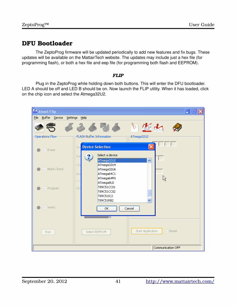
DFU BootloaderDFU BootloaderThe ZeptoProg firmware will be updated periodically to add new features and fix bugs. These
updates will be available on the MattairTech website. The updates may include just a hex file (for programming flash), or both a hex file and eep file (for programming both flash and EEPROM).
FLIP
Plug in the ZeptoProg while holding down both buttons. This will enter the DFU bootloader. LED A should be off and LED B should be on. Now launch the FLIP utility. When it has loaded, click on the chip icon and select the Atmega32U2.
September 20, 2012 41 http://www.mattairtech.com/
ZeptoProg™ User Guide
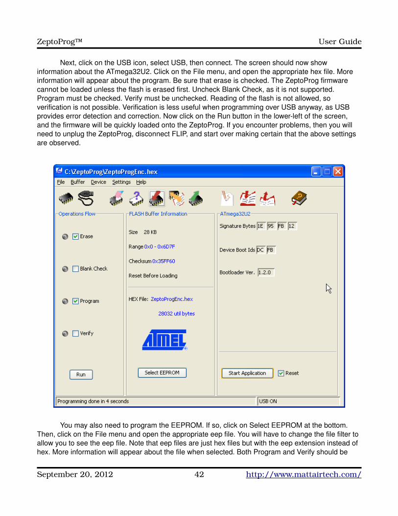
Next, click on the USB icon, select USB, then connect. The screen should now show information about the ATmega32U2. Click on the File menu, and open the appropriate hex file. More information will appear about the program. Be sure that erase is checked. The ZeptoProg firmware cannot be loaded unless the flash is erased first. Uncheck Blank Check, as it is not supported. Program must be checked. Verify must be unchecked. Reading of the flash is not allowed, so verification is not possible. Verification is less useful when programming over USB anyway, as USB provides error detection and correction. Now click on the Run button in the lowerleft of the screen, and the firmware will be quickly loaded onto the ZeptoProg. If you encounter problems, then you will need to unplug the ZeptoProg, disconnect FLIP, and start over making certain that the above settings are observed.
You may also need to program the EEPROM. If so, click on Select EEPROM at the bottom. Then, click on the File menu and open the appropriate eep file. You will have to change the file filter to allow you to see the eep file. Note that eep files are just hex files but with the eep extension instead of hex. More information will appear about the file when selected. Both Program and Verify should be
September 20, 2012 42 http://www.mattairtech.com/
ZeptoProg™ User Guide
checked. Click run to program the EEPROM.
Updating the firmware with recent versions of FLIP (ie: 3.4.7) may fail. If so, try using the batchisp command line tool included with FLIP.:C:\Program Files\Atmel\Flip 3.4.7\bin>batchisp device ATMEGA32U2 hardware USB operation erase F loadbuffer "C:\ZeptoProg_II.hex" program start reset 0
dfuprogrammer
TODO
Must erase chip first. Cannot read flash.
dfuprogrammer atmega32u2 erase
dfuprogrammer atmega32u2 flasheeprom ZeptoProg110111.eep (if applicable)
dfuprogrammer atmega32u2 flash suppressvalidation ZeptoProg110111.hex
September 20, 2012 43 http://www.mattairtech.com/
ZeptoProg™ User Guide
Legal NoticesLegal Notices
Copyright NoticesCopyright © 2009-2011, Justin Mattair (http://www.mattairtech.com/)Copyright © 2009-2010, Dean Camera (http://www.fourwalledcubicle.com/)Copyright © 2010, ChaN (http://elm-chan.org/)Copyright © 2003-2010, Atmel Corporation (http://www.atmel.com/)
Software DisclaimerThe author disclaim all warranties with regard to this software, including all implied warranties of merchantability and fitness. In no event shall the author be liable for any special, indirect or consequential damages or any damages whatsoever resulting from loss of use, data or profits, whether in an action of contract, negligence or other tortious action, arising out of or in connection with the use or performance of this software.
Hardware DisclaimerThe product described in this document is subject to continuous development and improvements. All particulars of the product and its use contained in this document are given by MattairTech LLC in good faith. However all warranties implied or expressed including but not limited to implied warranties of merchantability or fitness for particular purpose are excluded.
This document is intended only to assist the reader in the use of the product. MattairTech LLC shall not be liable for any loss or damage arising from the use of any information in this document or any error or omission in such information or any incorrect use of the product.
TrademarksZeptoProg™ is a trademark of MattairTech LLC.AVR® is a registered trademark of Atmel Corporation.All other trademarks are the property of their respective owners.
AcknowledgmentsThanks to Dean Camera (http://www.fourwalledcubicle.com/) for his excellent LUFA library, AVRISPmkII clone, and DFU bootloader, all of which are used in the ZeptoProg firmware. Thanks to the members of AVRfreaks (http://www.avrfreaks.net/) for their support. Finally, thanks to Atmel for creating a great product, the AVR.
September 20, 2012 44 http://www.mattairtech.com/
ZeptoProg™ User Guide
Appendix A: Powering Target via ZeptoProg 5VAppendix A: Powering Target via ZeptoProg 5V
WARNINGCare must be taken if using the Vtgt solder jumper to output 5V to the target board. Reverse polarity protection is not active in this
configuration, and there is no overload protection. Be sure that the target board can operate safely when powered from the ISP
connector. Do not attempt to program XMEGA devices with 5V.
TODO
opening the case (use flathead screwdriver at each corner multiple times around the perimeter, slowly lifting the top; the top is attached to the bottom via 4 plastic pins inserted into 4 plastic holes at each corner, lifting one corner too much before leveling out using the rest of the corners may break a pin)
solder jumper (solder J9 on bottom corner to connect Vbus 5V to Vtgt, use only 5V compatible targets)
September 20, 2012 45 http://www.mattairtech.com/
ZeptoProg™ User Guide
Appendix B: AVR Programmer Supported DevicesAppendix B: AVR Programmer Supported DevicesThe ZeptoProg supports all Atmel AVR microcontrollers with an ISP, PDI, or TPI programming
interface. These include the megaAVR series (ISP), the tinyAVR series (ISP, TPI), the XMEGA series (PDI), the USB AVRs (ISP), and the listed CAN and PWM AVRs. The following lists most of the supported models. Add to these the different voltage and speed grade variants.
ZeptoProg™ AVR Programmer megaAVR® Series Device Support
ATmega128, ATmega1280, ATmega1281, ATmega1284, ATmega1284P, ATmega128A, ATmega16, ATmega162, ATmega164A, ATmega164P, ATmega164PA, ATmega165, ATmega165A, ATmega165P, ATmega168, ATmega168A, ATmega168P, ATmega168PA, ATmega169, ATmega169A, ATmega169P, ATmega169PA, ATmega16A, ATmega16HVB, ATmega2560, ATmega2560, ATmega2561, ATmega32, ATmega324A, ATmega324P, ATmega324PA, ATmega325, ATmega3250, ATmega3250A, ATmega3250P, ATmega325A, ATmega325P, ATmega328, ATmega328P, ATmega329, ATmega3290, ATmega3290A, ATmega3290P, ATmega329A, ATmega329P, ATmega329PA, ATmega32A, ATmega32C1, ATmega32HVB, ATmega32M1, ATmega48, ATmega48A, ATmega48P, ATmega48PA, ATmega64, ATmega640, ATmega644, ATmega644A, ATmega644P, ATmega644PA, ATmega645, ATmega6450, ATmega6450A, ATmega6450P, ATmega645A, ATmega645P, ATmega649, ATmega6490, ATmega6490A, ATmega6490P, ATmega649A, ATmega649P, ATmega64A, ATmega64HVE, ATmega8, ATmega8515, ATmega8535, ATmega88, ATmega88A, ATmega88P, ATmega88PA, ATmega8A, ATmega8HVD
ZeptoProg™ AVR Programmer tinyAVR® Series Device Support
ATtiny10, ATtiny12, ATtiny13, ATtiny13A, ATtiny15, ATtiny167, ATtiny20, ATtiny2313, ATtiny2313A, ATtiny24, ATtiny24A, ATtiny25, ATtiny26, ATtiny261, ATtiny261A, ATtiny4, ATtiny40, ATtiny4313, ATtiny43U, ATtiny44, ATtiny44A, ATtiny45, ATtiny461, ATtiny461A, ATtiny48, ATtiny5, ATtiny84, ATtiny85, ATtiny861, ATtiny861A, ATtiny88, ATtiny9
ZeptoProg™ AVR Programmer XMEGA™ Series Device Support
ATxmega128A1, ATxmega128A1_revD, ATxmega128A1U, ATxmega128A3, ATxmega128A4, ATxmega128D3, ATxmega128D4, ATxmega16A4, ATxmega16D4, ATxmega192A1, ATxmega192A3, ATxmega192D3, ATxmega256A1, ATxmega256A3, ATxmega256A3B, ATxmega256D3, ATxmega32A4, ATxmega32D4, ATxmega384A1, ATxmega64A1, ATxmega64A3, ATxmega64A4, ATxmega64D3, ATxmega64D4
ZeptoProg™ AVR Programmer USB AVR Device Support
AT90USB1286, AT90USB1287, AT90USB162, AT90USB646, AT90USB647, AT90USB82, ATmega16U2, ATmega16U4, ATmega32U2, ATmega32U4, ATmega32U6, ATmega8U2
ZeptoProg™ AVR Programmer CAN AVR and PWM AVR Device Support
AT90CAN128, AT90CAN32, AT90CAN64, AT90PWM2, AT90PWM216, AT90PWM2B, AT90PWM3, AT90PWM316, AT90PWM3B
September 20, 2012 46 http://www.mattairtech.com/