z! HYDROSTATICS OF A FLUID BETWEEN PARALLEL … · · 2017-06-26RESEARCH LAB ORATORIES BROWN...
45
TECHNICAL NOTE R-159 w c ' .E HYDROSTATICS OF A FLUID z! BETWEEN PARALLEL PLATES AT LOW BOND NUMBERS Microfiche (MF) ff 653 July65 RESEARCH LABORATORIES BROWN ENGINEERING COMPANY, ZNC. HUNTS VZL LE, A LABAM A https://ntrs.nasa.gov/search.jsp?R=19660004275 2018-06-07T15:14:51+00:00Z
Transcript of z! HYDROSTATICS OF A FLUID BETWEEN PARALLEL … · · 2017-06-26RESEARCH LAB ORATORIES BROWN...

TECHNICAL NOTE R-159
w c ' .E
HYDROSTATICS OF A FLUID z!
BETWEEN PARALLEL PLATES
A T LOW BOND NUMBERS
Microfiche (MF)
ff 653 Ju l y65
RESEARCH LABORATORIES
BROWN ENGINEERING COMPANY, ZNC.
HUNTS VZL LE, A LABAM A
https://ntrs.nasa.gov/search.jsp?R=19660004275 2018-06-07T15:14:51+00:00Z

I
1
i I
I
I
I I ~
I
I
I
TECHNICAL NOTE R- 159
HYDROSTATICS O F A PA 6 LLEL PLATES A T LOW
October, 1965
P repa red For
PROPULSION DIVISION P & V E LABORATORY
GEORGE C. MARSHALL SPACE FLIGHT CENTER
BY
RESEARCH LAB ORATORIES BROWN ENGINEERING COMPANY, INC.
Contract No. NAS8-20073
Prepared B y
F. W. Geiger

ABSTRACT
/ 3 5 & 4 The hydrostat ics of a fluid between pa ra l l e l plates at low but
positive Bond numbers is re-examined as a pre l iminary to dynamic
calculations.
study by Reynolds.
The resu l t s of this study differ f r o m those of a previous
It is believed that the r e su l t s of Reynolds are in
e r r o r ,
Approved
E. J? Rodge r s , Manager Mechanics and Thermodynamics
Department
Approved
Di rec to r of Research
. . 11

TABLE OF CONTENTS
INTRODUCTION
STATEMENT OF THE PROBLEM
ANA LYSIS
P r e s s u r e in the Liquid as a Function of Depth
Integration of the Differential Equation for Bond Numbers Grea ter Than Zero
The Range of Values of s
Calculation Procedure for Positive Bond Numbers and fo r Small Contact Angles
A Special Case: Bond Number Ze ro
DISCUSSION O F RESULTS
Results for One Bond Number and Contact Angle
The Results of Reynolds a r e Questionec!
I
CONCLUSIONS
LIST OF REFERENCES
Tr APPENDIX A. FORTRAN IV PROGRAM FOR e <
APPENDIX B. SUBROUTINE ELLIP
Page
1
3
5
5
7
10
13
14
18
18
2 1
23
24
2 5
34
iii

1 i I I I I I I I I I I I i I
LIST OF FIGURES
Figure
1 Fluid Between Two Para l le l W a l l s Which A r e Also Pa ra l l e l to the Effective Acceleration of Gravity
2 The Surface of the Liquid at Bond Number Z e r o
3 Displacement of the Surface, 8 = 5 O , Bo = 119. 5
LIST OF TABLES
Table
1 Input Data fo r Calculations
2 Output Data from Calculations
3 Comparison Betw,een F ( B , 6) and Reynolds' Results at the W a l l s
i v
Page
4
16
19
20
20
22

LIST O F SYMBOLS
A A constant in the pressure equation, lbrn/ft-sec'
B Bond number in Reynold's notation
Bo Bond number in present notation
C An integration constant
E ( k )
E(k, a)
Complete elliptic integral of the second kind
Elliptic integral of the second kind
F(B, 0) A function used i n comparing r e su l t s of present paper with those of Reynold's paper
Elliptic integral of the first kind F ( k , CY)
P
R
S
T
W
2;
Y
'The effective acceleration of gravity, f t / set'
The y-coordinate of the sur face of the liquid ( o r fluid), f t
Modified y-coordinate of the surface (h - T) , ft
Complete elliptic integral of the first kind
Charac te r i s t ic length used by Reynolds ( w / 2 ) , f t
P r e s s u r e of vapor and gas above liquid, l bm/ f t - sec
Static p r e s s u r e in the liquid, lbrn/f t -sec2
2
Radius of curvature of the sur face , f t
Dimensionless parameter proport ional t o ver t ica l displace - ment of sur face
Surface tension of liquid, l b m / s e c 2
Width of tank, ft
Distance a c r o s s tank, ft
Reynolds' ver t ica l displacement (h - hm), ft
V

I
t
Y
e
P
T
LIST O F SYMBOLS (Continued)
Distance perpendicular to x-direction, f t
Contact angle between liquid and wall, r ad
Density of the liquid (fluid), lbrn/ft3
Distance related to A (Alpg), f t
Sub s c r i pt
m Indicates mean or average value
At point where dh/dx = 0 (at middle of tank) 0
S Indicates surface condition
U Upper value o r value at the wall
v1

INTRODUCTION
When the valves in the propellant lines of a mis s i l e in flight a r e
suddenly closed, there a r e oscillations of fluid flow a t the propellant tank
outlets. When, in addition, ullage rockets a r e operating, the effective
accelerat ion of gravity (for the fluid in the tanks) is v e r y low but positive
and is directed along the axes of symmetry of the tanks.
of this project to investigate the behavior of the liquid-vapor (plus g a s )
interfaces in the propellant tanks under these conditions.
It i s the purpose
F o r the propellants under consideration (specifically, liquid
hydrogen and liquid oxygen), the contact angles a r e smal l . Under the
conditiolis of low accelerat ion (small Bond number) and small contact
angle, the deflections f rom any constant height and the slopes of the
iiquiu-gas interface will be moderate to la rge over a fair portion of the
tank.
involve sma l l deflections of this surface f r o m a constant height and s m a l l
slopes of that surface a r e invalid.
Then those assumptions of the usual s m a l l perturbation theory which
h-or the present problem i t is appropriate to a s sume perturbations
It i s then necessa ry that (1) the s ta t ic about a static equilibrium surface.
equilibrium surface be known wi th considerable accuracy and that ( 2 ) dy-
namic variations f rom that surface be amenable to analysis .
Propellant tanks a r e usually c i rcu lar cyl inders , and a final a i m of
analysis must be to solve the problem in which the s ta t ic case is axially
symmet r i c . However, for the moment, the dynamic two-dimensional
( three-dimensional , including t ime) problem s e e m s difficult enough to
handle; and efforts have been confined to solving that problem.
solution required i s therefore the two-dimensional one.
The s ta t ic
Treatment of the two-dimensional static problem is not new. The
problem is reported by Otto1 to have been t rea ted by both Reynolds2 and
Benedikt for the case of ver t ica l walls. 3 Some justification of the present
1

paper , which deals in detail with the s a m e problem, is therefore required,
The justif ications a r e these :
0 Efforts to obtain the original papers of Reynolds and Benedikt were unsuccessful.
0 What is needed he re a r e detailed calculations fo r par t icu lar Bond numbers and for particular low contact angles. not be expected that either the needed accuracy was attained o r the par t icular contact angles were t rea ted in the or iginal papers .
It could
0 It is shown that the results of Reynolds, as repor ted by Otto, a r e a t var iance with those to be obtained through the present analysis. I t is believed that Reynolds' resu l t s a r e in e r r o r .
This paper s t a r t s with the governing equations, develops the
diffei-entia1 eyudi iur i I'or tile vertical displacement of the sur face , integrates
that equation for positive Bond numbers and for sma l l contact angles, t r e a t s
the spec ia l ca se of Bond number z e r o , calculates r e su l t s for a par t icular
Bond number and contact angle, and, finally, questions the resu l t s of
Reynolds.
2

STATEMENT OF THE PROBLEM
I I I I I I I I I I I I
Consider two plane para l le l walls a distance w apar t , as in
Figure 1, which extend to infinity (o r to a ve ry long distance compared
to w) both out of and into the plane of the f igure.
choose a horizontal o r x-axis perpendicular to the walls at an a r b i t r a r y
ver t ica l location and a y-axis perpendicular to the x-axis and half-way
between the walls".
the minus y-direction.
mean depth, hm. Consider the density of the fluid, p , its surface tension,
T, the p r e s s u r e of the gas (plus vapor) above the liquid, P, the effective
accelerat ion of graxvity, and the contict angle of the liquid at the wall, 8,
to be constant.
of x.
In the plane of the figure
Let the effective accelerat ion of gravity, g, a c t in
Let a fluid fill the lower pa r t of the region to a
Find the location of the surface of the liquid as a function
-1.
"'The la t te r choice is made only because of the symmetry of the problem but is not essent ia l in obtaining the solution.
3

I Y I I I I I I I I i I
P
--
Figure 1 . Fluid Between T w o Pa ra l l e l Plane W a l l s Which are A l s o L’arallcl to t h e E i f f e c t i v e A, cclleration of Grav i ty
-1

ANALYSIS
PRESSURE IN THE LIQUID AS A FUNCTION OF DEPTH
The p r e s s u r e , p, at any point (x, y ) i n the fluid is given by
p t p g y = P t A ( 1 )
where A is a constant to be determined.
be y = h(x) and the p r e s s u r e a t the surface be ps.
Let the equation of the sur face
Then
p s t p g h = P t A ,
The p r e s s u r e at the sur face is related to the sur face tension, T, by
T = p - - R Ps
where R is the radius of curva ture of the sur face , o r by
where
The elimination of ps from Equations 2 and 3b yields
= p g h - A = p g ( h - T ) T (d'hldx')
[ l + ( d h / d ~ ) ~ ] ~ / ~
T is a rriatheniatical (not physical) value of 11 for which d 2 h / d x Z = 0.
( h = T will generally be below the surface of the liquid. ) Before Equation 4
is integrated, T w i l l be obtained.
will then b e known.
The p r e s s u r e a t any point in the liquid
' T h e t e r m s of Equation 4 a r e integrated with respec t to x f r o m
wall t o Wall. 'The resu l t is
5

1 - - - h(x) dx - T W T
It is a function of the ainount of fluid in the tank.
value of 11. Then
Let h, be the mean
p w l 2 1 .
I -1 J-w/ 2
s o that
dh /dx ~-
[l t ( d h / d ~ ) ' ] ~ / ~ - w / 2 * I 2 ) Let 8 be the contact angle of the liquid a t the wall. Then
dh W
dx 2 - = cot 8 for x = -
W - - cot 8 for x = - - dh dx 2 - -
so that
I Now
6

and Equation 5 can be wri t ten
cos e . 2 T ~ = h ~ - - P g w
Then
and Equation 1 becomes
s o that the p r e s s u r e is calculable for s a y point in the fluid.
this equation holds no mat te r where the origin of coordinates is located
s ince its location affects y and hm similarly.
Observe that
INTEGRATION O F THE DIFFERENTIAL EQUATION FOR BOND NUMBERS GREATER THAN ZERO
Equation 4 will now be integrated. Let E = h - T . Then Equation 4
becomes
This can be integrated once a f te r multiplying both s ides by dE/dx.
resu l t i s
The
where c is the constant of integration.
d?i/dx = 0 (a t the middle of the tank).
unknown. ) Then
Let Eo be the value of A where
(The value of E o is a t present
2 2 T P g
c = h o t-
7
and
or
s o t ha t
or s
L X = * - W
( 1 t so - s L ) ds
1 [ . (s2 - s o ) 2 ( 2 - s L $. s ; ) p
S O
w h e r e B, is t h e Bond n u m b e r , def ined h e r e b y
P P L Bo = - T

- .
On making the successive substitutions,
2 2 t = 1 t s o - s
s in CY = t
while retaining s in the upper l imit of integration and expressing constants
in t e r m s of s o J this becomes
1 J v / z
2
dJI 1
bin 1
1 t s;/2 T I 2 I 2 s o - s 2 )
where
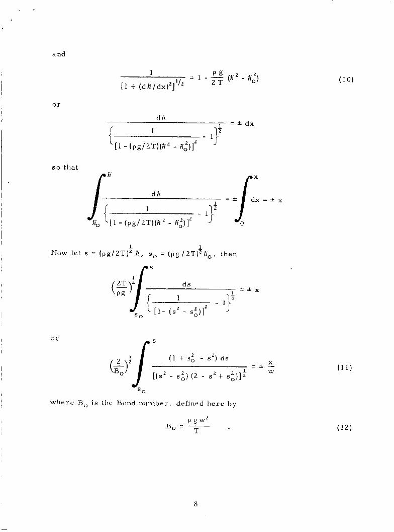
9
1. is the complete elliptic integral of the first kind,
is the elliptic integral of the f i r s t kind,
is the complete elliptic in tegra l of the second kind, and
is the elliptic integral of the second kind.
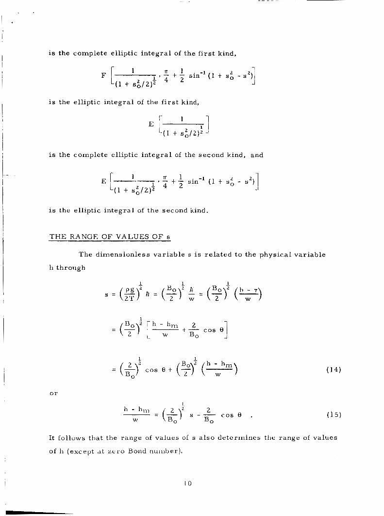
THE RANGE OF V A L U E S O F s
The dimensionless var iable s is re la ted to the physical variable
h through
or 1 -
h - h,,, 2 W
= (&y s -B, C O S e . 0 5)
It follows that the range of values of s also de termines the range of values
of h (except at z e r o Bond number).
10

An equation previously obtained was
1 - - 1 - - p g (E2 - tz,') 1 [ l t ( d E / d ~ ) ~ ] ' 2T
I which can be writ ten 1
2 2 = 1 t s o - s . 1
[ I t (dE/dx)']Z
, The maximum values of IdE/dxl = Idh/dxI and of s occur a t the wal l
[x = ( 1 / 2 ) w ] , where Idh/dxI = cot 8.
s , su ( for s upper). Then a t the wall
Cal l the corresponding value of i
and
= s in 8 1
[ l t (dE/dx)']Z
2 2 su = 1 t so - s i n 8
2 X 1 W 2 I Substitution of s2 = su at - = * - into Equation 13 yields
1 1 2 1
( 1 t S 3 2 ) Z
11

This equation de termines so, 2 and Equation 17 then determines s:.
In o rde r to be able to convert s back to a physical coordinate (h) ,
it remains to determine the s igns of so and s .
only fo r s 2 L so o r for
Equation 13 has significance 2
2 2 (19) s - so = ( s - so) (s t so) 2 0 .
Now f r o m Equation 14 one obtains
1 B 2 h - h o
s - s o = ( y ) ( ) Tr h - ho
2 W F o r 8 < - it follows that physically - L 0 s o that
s - s o = o 1 .
Then, f r o m Equation 19,
s t s o 2 0
and f rom the above two equations
s 2 0
so 2 0
and
Tr F o r 8 > 7 i t follows that
h - ho s o W
12
s - s o z o
s t s 0 ~ O
, 5 5 0
so I 0
and
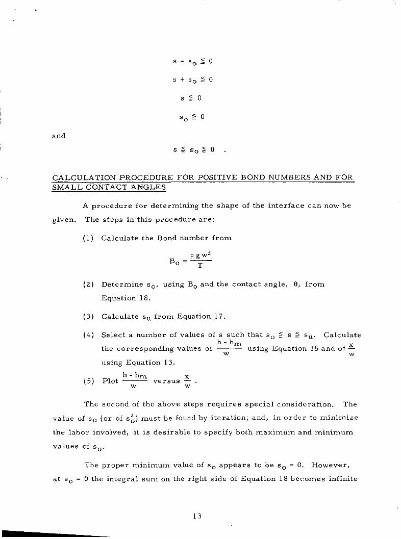
CALCULATION PROCEDURE FOR POSITIVE BOND NUMBERS AND FOR SMALL CONTACT ANGLES
A procedure for determining the shape of the interface can now be
The steps in this procedure a re : given.
Calculate the Bond number f r o m
Determine s o , using Bo and the contact angle, 8, f r o m
Equation 18.
Calculate su f r o m Equation 17.
Select a number of values of s such that s o 5 s 5 su.
the corresponding values of
using Equation 13.
Calculate h - h m X using Equation 15 and of -
W W
h-h, X Plot ve r sus - . W W
The second of the above steps requi res spec ia l consideration. The
value of so (o r of si) must be found by i terat ion; and, in o r d e r to minimize
the labor involved, i t is desirable to specify both maximum and minimum
values of so.
The proper minimum value of s o appears to be s o = 0. However,
at so = 0 the integral sum on the right side of Equation 18 becomes infinite
13

.
( o r that equation cannot possibly be satisfied unless the Bond number is
a l so infinite). F o r finite Bond numbers, then, the substitution so = 0
yields an infinite value for the right side of the equation.
F o r the problems of p re sen t interest 8 is smal l , and an upper l imit
< 0 , Tr h o - h m
for so will be found pr imar i ly for such problems. F o r 8 < - , 2 W
Tr and it follows f r o m Equation 2 0 that for 8 < - , 2
F o r smail 6 one ma): as well use
1 2 -
) is then the required upper bound. One may use it as a f i r s t guess
in the i terat ion process for calculating so.
h - h m X A FORTRAN IV computer program for calculating and -
W W
for small contact angles has been written by Allen G. Collier of the
Scientific Programming Section of Brown Engineering Company, Inc. His
main p rogram is given i n Appendix A while his subroutine for calculating
the elliptic integrals is given in Appendix B.
routine utilized the method of Fett is and Cashin . His elliptic integral sub- 4
A SPECLAL CASE: BOND NUMBER ZERO
In this section it is demonstrated that a t Bond number ze ro the
sur face of the fluid is that of a right c i rcu lar cylinder.
the surface is obtained.
The equation of
F r o m Equations 4 and 8 it follows that
T - = R p g ( h - T )
cos e) , = p g (h-h , t - 2T P g w
14

where R is the local radius of curvature of the sur face , o r that
- - W - 2 cos e t B, ("m, . R
At Bond number zero , then, it follows that
(21 1 W R = - sec 8 , 2
that the radius of curva ture of the surface is a constant, o r that in the h -x
plane the c ross -sec t ion of the surface is c i r cu la r with the radius as given
above.
the p r e s s u r e must be the same at a l€ points In the flukd, which means that
the radius of curva ture of the surface must be constant, and since the fluid
must reach the wal l at the contact angle. This s ame type of resu l t i s found
by Li5, who determined that the interface was spher ica l for a cylindrical
tank, using the principle of minimum energy. )
(This equation is expected since at Bond number zero , s a y g = 0,
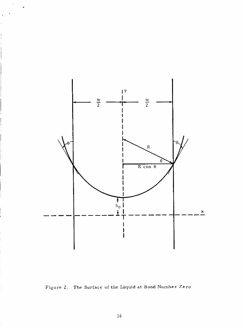
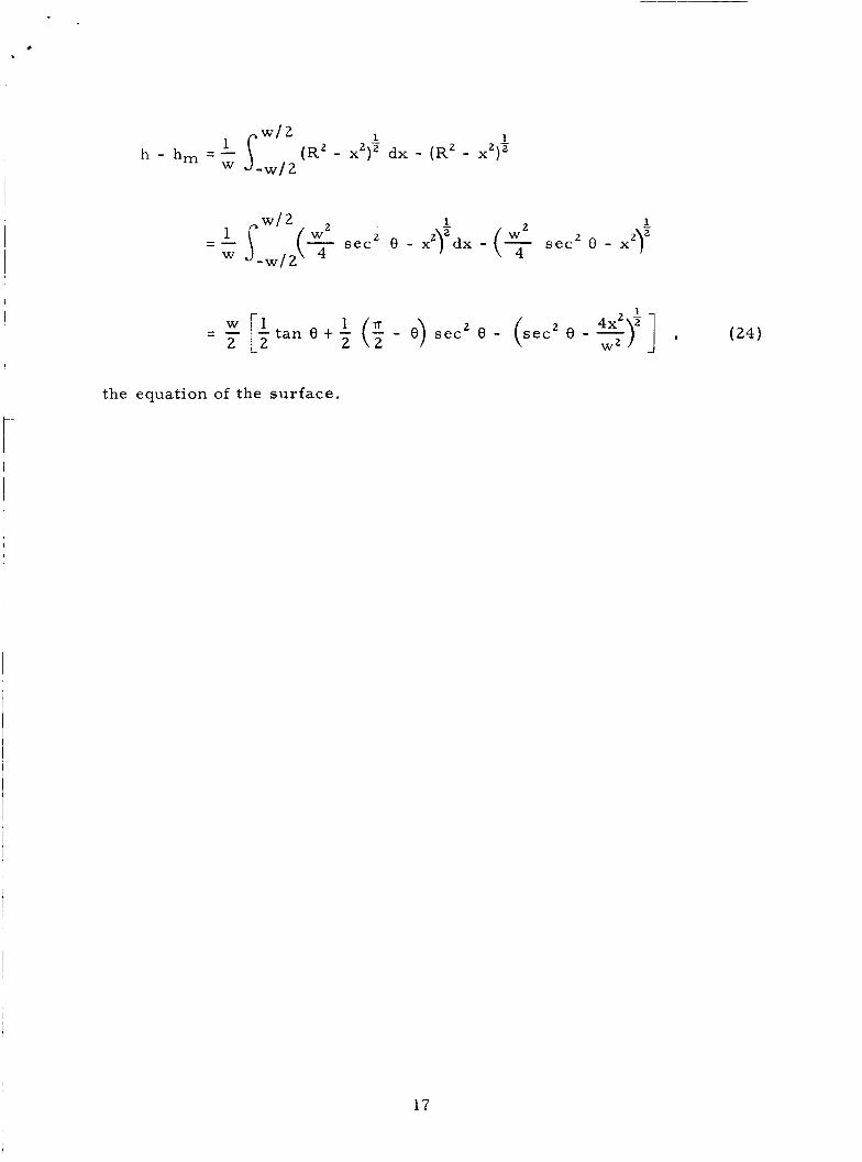
It remains only to obtain the equation of the sur face . The equation
of the sur face ( see F igure 2 ) is
[h - (R t h0)]' t x2 = RZ
f r o m which 1
h = R t ho - (R2 - x2)' .
h, i s assumed to be known
On solving the above two equations for h - hm, substituting the value of R
f r o m Equation 21, and integrating, one obtains
15
W - 2
I Y I 'I'
I
I I i
I
W - 2
X -----
F i g u r e 2 . T h e S u r f a c e of t h e L iqu id at Bond Number Z e r o
16
I .
1 1
(R2 - x2)' d x - (R2 - x2) '
1 - 2 1 - sec 2 8 - X2I2dx - (% s e c 2 0 - x2Y
-w/2 W
1
(24) 1 4x2 2 - - [I t an e t - (: - e) sec2 e - (sec2 e - -) ] ,
- 2 L2 2 W2
the equation of the sur face .
17

t
DISCUSSION OF RESULTS
RESULTS FOR ONE BOND NUMBER AND CONTACT ANGLE
The miss i le of immediate concern is the Saturn V. The fuel (liquid
hydrogen) tank of the S- IV B s tage of that mi s s i l e was selected f o r study
under low accelerat ion (corresponding to the use of ullage rockets) .
The input data for the calculations a r e given in Table 1. In the
table the width, w, used was the diameter of the tank. (It is recognized
that the r e a l tank is axially symmetr ic . ) The elliptic integrals were to be
calculated to a n accuracy of
The output data frzrr: t h e ca lcu la t i cns a r e given ill Table 2 2nd a r e
plotted in Figure 3.
data. These a r e :
Several observations a r e to be made concerning these
(1) The Bond number calculated is approximately 120. The
Bond number using the half-width of the tank (the radius of
the r e a l tank) a s a character is t ic length would have been
about 30.
( 2 ) The calculation is limited to a comparat ively sma l l number
of values of s.
been calculated a s desired.
Obviously as many m o r e points could have
( 3 ) The value of so is clearly the first value of s in the table.
(4) The difference between the final value of x / w and 1 / 2 indicates
the overal l accuracy of the program.
( 5 ) Deflections and slopes of the sur face near the wall a r e not
sma l l even for this r a t h e r high Bond number.
surface a r e appreciable over about twenty percent of the
width of the tank.
Slopes of the
18

n i
7
0
m d
3 . x
N
0
3
0
0
19

TABLE 1
INPUT DATA F O R CALCULATIONS
p = 4.44 lb/f t3 (liquid hydrogen)
= 3 2 . 3 x f t l sec2
T = 1 7 5 X 1 O m 6 X 32. 2 pdl/ft (liquid hydrogen)
w = 2 1 . 7 f t
51T 180
r a d -
ACC = 0. 00000001 (Accuracy of elliptic in tegra l )
TABLE 2
OUTPUT DATA FROM CALCULATIONS
Bond Number 0. 1 1 9 4 7 1 5 2 t 0 3 8 = 5" S x / w h - h,
W
0. 55026502-02 0.00000000 0. 2 3 0 9 4 1 6 8 - 0 1 0. 19329778-00 0 . 4 0 6 8 5 6 8 7 - 0 1 0. 24597565-00 0. 58277206-01 0. 27900860-00 0. 75868724- 01 0. 30314618-00 0. 9 3 4 6 0 2 4 3 - 0 1 0. 32216351-00 0. 1 1 1 0 5 1 7 6 t 0 0 0. 33784146- 00 0. 2 1 6 6 0 0 8 7 - 0 0 0 . 39780985-00 0. 322149'18-00 0 . 4 3 2 1 5 3 4 3 - 0 0 0 . 4 2 7 6 9 9 1 0 - 00 0 . 4 5 5 2 8 3 9 0 - 00 0. 5332482 1 - 00 0 . 4 7 1 8 0 0 1 7 - 0 0 0. 6 3 8 7 9 7 3 2 - 0 0 0 .48372990-00 0 . 7 4 4 3 4 6 4 3 - 0 0 0 . 4 9 2 10297- 00 0. 8 4 9 8 9 5 5 4 - 0 0 0 . 4 9 7 4 6 1 1 6 - 0 0 0. 955-14466-00 0. 50003424- 00
-0. 15964731 - 01 -0. 1 3 6 8 8 6 5 8 - 0 1 -0 . 1 1 4 1 2 5 8 5 - 0 1 - 0 . 9 1 3 6 5 1 2 6 - 0 2 - 0 . 6 8 6 0 4 3 9 9 - 0 2 - 0 . 4 5 8 4 3 6 7 1 - 0 2 - 0 . 2 3 0 8 2 9 4 4 - 0 2
0. 11 348142-01 0. 25004579-01 0. 38661015-01 0. 5231 7452-01 0. 6 5 9 7 3 8 8 8 - 0 1 0. 78630324- 01 0 . 9 3 2 8 6 7 6 1 -01 0. 1 0 6 9 4 3 2 0 t 0 0
20

. THE RESULTS OF REYNOLDS ARE QUESTIONED
It is reported by Otto' that Reynolds2 has attacked the present
problem, and Otto repor t s Reynolds' resu l t s as a plot of ver t ica l dis-
placement ve r sus horizontal distance for var ious Bond numbers a t fixed
contact angle (F igure 5 of Reference 1). Unfortunately efforts to obtain
Reynolds' paper were unsuccessful s o that comments on his analysis
cannot be made.
The resu l t obtained in the preceding section for the displacement
of the liquid a t the walls appeared to be too la rge t o f i t Reynolds' resu l t s .
(Reynolds' charac te r i s t ic length is half of that used in this paper . ) As a
resu l t , some method of checking the accuracy of his r e su l t s was sought.
The method used was to es tabl ish a lower limit for hU - hm (the displace-
ment a t the wall) fo r s m a l l values of 8 and to compare the resu l t s obtained
at Reynolds' Bond numbers and a t one of his two contact angles with his
deflections (at the wall).
lT F r o m Equations 14 and 1 7 it follows that fo r 8 - 2
1 1 2 1 2 a B o z h u - h m
su = (1 t so - s i n e)" = (5) cos e t (F) W
o r that
1 L 2
= (&V (1 t s~ - s i n el2 - - COS e . k - h m W BO
s o is a function of both Bond number and contact angle.
t ac t angles it is s m a l l compared t o unity for moderate Bond numbers ,
approaches ze ro a s the Bond number inc reases , and approaches infinity
a s the Bond number dec reases towards zero.
F o r sma l l con-
The inequality
1 hu - hm L 2
(1 - s in e)2 - - COS e = F(B,, e ) W ' (&Y BO
21
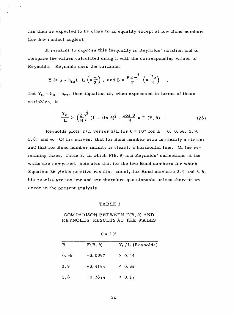
can then be expected to be close to an equality except at low Bond numbers
( for low contact angles).
It remains to expres s this inequality i n Reynolds' notation and to
compare the values calculated using it with the corresponding values of
Reynolds. Reynolds uses the variables
Y (= h - hm), L (= F) , Let Yu = hu - hm, then Equation
var iab les , is
and B = - P g L 2 (=?) . T
25, when expressed in t e r m s of these
1 2 1 - cos e Y, L > (ii (1 - sin e ) 2 - - B = F (BA .
Reynolds plots Y / L ve r sus x / L for 0 = 10" for B = 0, 0. 58, 2 . 9 ,
5 .6 , and a. Of his curves , that for Bond number ze ro is c l ea r ly a c i r c l e ;
and that for Bond number infinity is clear ly a horizontal line. Of the r e -
maining th ree , Table 3, i n which F(B , 0) and Reynolds' deflections a t the
walls a r e compared, indicates that f o r the two Bond numbers for which
Equation 26 yields positive resu l t s , namely for Bond numbers 2. 9 and 5.6,
h i s r e su l t s a r e too low and a r e therefore questionable unless there is an
e r r o r i n the present analysis.
TABLE 3
COMPARISON BETWEEN F(B, e) AND REYNOLDS' RESULTS AT THE WALLS
e = 100
B F(B, e) Yu/ L (Reynolds)
0. 58 - 0 . 0097 > 0.44
2 . 9 to. 4154 < 0.38
5 .6 t 0.36 74 < 0.17
22

CONCLUSIONS
The present repor t r e su l t s from a need for accuracy in s ta t ic cal-
culations (for low contact angles and Bond numbers) in o r d e r that the cal-
culated s ta t ic surfaces may se rve a s the unperturbed su r faces for dynamic
calculations.
contact angle.
Results a r e obtained f o r one par t icular Bond number and
It is believed that the accuracy used in calculating the elliptic
integrals involved is sufficient.
for a t l eas t two Bond numbers the displacements calculated ( a t the wal ls)
will be l a r g e r than those obtained by Reynolds.
believed to be i n e r r o r .
It is shown that for one contact angle and
Reynolds' resu l t s a r e
2 3

LIST OF REFERENCES
1 . Otto, E. W. , "Static and Dynamic Behavior of the Liquid-Vapor Interface During Weightlessness", Published by NASA in Proceedings of the Conference on Propel lant Tank P res su r i za t ion and Stratif ication, Vol. 11, pp. 281-354, January 20, 21, 1965
2. Reynolds, William C. , "Hydrodynamic Considerations fo r the Design of Systems for Very Low Gravity Environments", Rep. LG- 1 , Stanford University, September 1961
3. Benedikt, E. T. , "Epihydrostatics of Liquids i n Vert ical Tanks", Rep. ASG-TM-61-48, Norair Div. , Northrop Corp. , June 1961
4. Fe t t i s , H. E. and J. C. C a s h , "FORTRAN P r o g r a m s fo r Computing Elliptic Integrals and Functions", Applied Mathematics Resea rch Laboratory, Aerospace Research Labora tor ies , Wright- Pa t t e r son Air F o r c e Base , May 1964
5. Li, Ta, "Hydrostatics in Various Gravitational Fields", Journa l of Chemical Phys ics , Vol. 36, No. 9, pp. 2369-2375, May 1, 1962
24

APPENDIX A
Tr FORTRAN IV PROGRAM FOR 0 < 7
DESCRIP‘TION O F PROGRAM
2. Solve the following equation for s o
1 - 2 3 . Select values of s ranging from so to ( 1 t so - s i n e ) 2 .
25
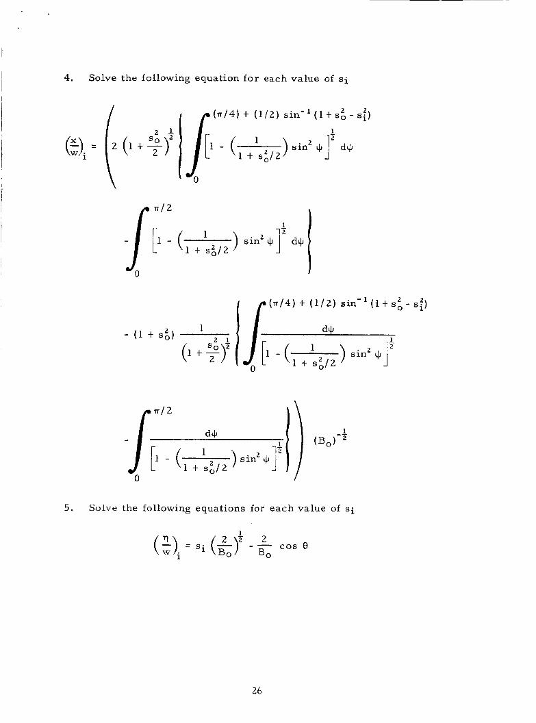
4. Solve the following equation for each value of S i
1
1 ) sin2 $1' d+ r 1' - ( 1 t s 3 2
5. Solve the following equations for each value of si
26
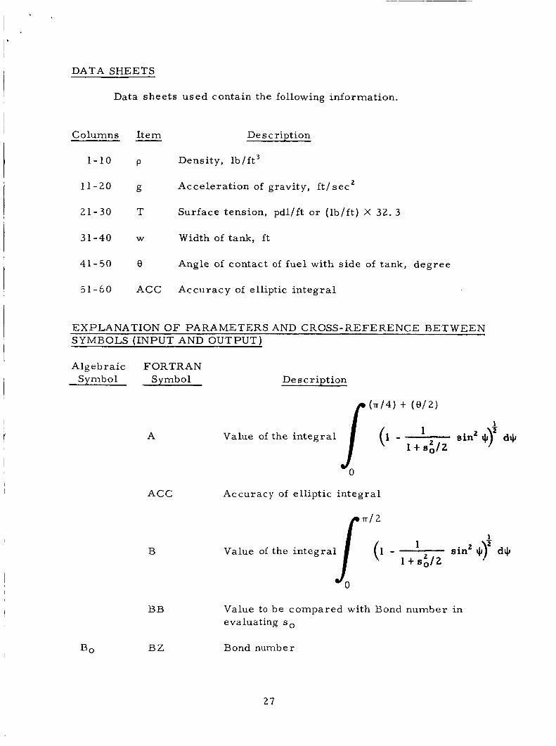
DATA SHEETS
Data sheets used contain the following information.
Columns I tem Des c ription
1-10 p Density, lb/ft3
11-20 g Accelerat ion of gravity, f t / s ec2
21-30 T Surface tension, pdl/ft o r ( lb / f t ) X 32. 3
31-40 W Width of tank, f t
41-50 e Angle of contact of fuel with s ide of tank, degree
51-59 ACC Accuracy of elliptic in tegra l
EXPLANATION O F PARAMETERS AND CROSS-REFERENCE BETWEEN SYMBOLS (INPUT AND OUTPUT)
Algebraic FORTRAN Symbol Symbol Description
(d4) 4- ( 0 / 2 )
1
sin2 $7 ~ I J , 1
- 1 t s 3 2 Value of the in tegra l A
BO
ACC Accuracy of elliptic integral
B
BB
BZ
Value to be compared with Bond number in evaluating s o
Bond number
27

Algebraic FORTRAN Svmbol Svmbol
C
h-h , W
P
D
DB
DBL
DB U
DS
ETAW
G
I
K
RHO
RK
Description
(d4) $- ( 0 / 2 )
1 d4J
1 - 1 sin2 +y S( 1 t 8 3 2
Value of the integral
0
1 d4J
sin2 +r 1
1 t s;/2
Value of the integral
Difference between BB and BZ for a par t icu lar value of so
Difference between BB and BZ for a lower l imit of so
Difference between BB and BZ fo r a n upper l imit of so
Increments of s used for calculating (x /w) and (rllw)
Ratio of the ver t ica l displacement f r o m the mean of a point to the width of the tank (q /w)
Acceleration of gravity
Index item
Control item
Density
1 K of - k' sin' +)' d+
S S Dimensionless quantity
28

Algebraic Svmbol
S U
S O
T
0
W
FORTRAN Svmbol
SL
su
su
so
s1
T
THETA
THETAR
UL
W
XW
Des c riDtion
A lower limit of so
An upper limit of so
The upper limit of s
The lower l imit of s
Used a s a next guess in i terat ing for so
Surface tension
Angle of contact of fluid with side of tank in degrees
THETA in radians
Upper limit of elliptic integral
Width of tank
Ratio of the l a t e ra l displacement of a point f r o m the middle of the tank to the width of the tank
FORMAT O F DECK AND OPERATING INSTRUCTIONS
The format of the operating decks is dependent upon the operating
sys t em of the computer being used.
checked out on the Univac 1107.
FORTRAN IV could be used.
be run under a monitor operating system.
operating deck should be:
This p rogram was wri t ten and
However, any computer that accepts
The program was wri t ten so that it could
The genera l format of the
1. Control c a r d s
2. Source o r object ca rds for the main program
3 . Source o r object ca rds for the E L L I P subroutine
4. Card indicating that data follows
29

5 . Data c a r d ( s )
6. B l a n k c a r d
7. Ca rd ( s ) returning control t o monitor sys t em
30

I
31

32

3 3

APFENDIX B
SUBROUTINE ELLIP (Computes the Elliptic Integrals)
3 4

14
35

j
5=1.
36

37

1 OSICINATIN G ACTIV ITY (Corporele eulhor)
Resea rch Laborator ies
Huntsville, Alabama Brown Engineering Company, Inc.
3 . REPORT T I T L E
2 a REPORT SECURITY C LASSIFICATION
Uncla s s i f ied
N/A Z b GROUP
"Hydrostatics of a Fluid Between Para l le l P l a t e s a t Low Bond Numbers"
7.. T O T A L N O . O F P A G E S
44
4 DESCRIPTIVE NOTES ( T y p e of report and lnclurlve date.)
Technical Note, October 1965
Geiger, Dr . F rede r i ck W. 5 AUTHOR(S) f t a ~ t name. Ifrat name. Inltial)
7 6 . NO. O F R E F S
5 6 . R E P 0 RT D A T E
October 1965 811. CONTRACT O R G R A N T NO.
NAS8- 2 007 3 b. P R O J E C T NO.
N/A C .
d.
I O . A V A I L ABIL ITY /L IMITATION NOTICES
No ne
O b . OTUER R PORT NG'S? ( A s y other numbera lhat may be asal&an.d Uti. rapor3
None
11. SUPPLEMENTARY NOTES
None
12. SPONSORING M I L I T A R Y A C T I V I T Y
Marshal l Space Flight Center NASA
13. ABSTRACT
The hydrostat ics of a fluid between pa ra l l e l plates a t low but positive Bond numbers is re-examine( a s a pre l iminary to dynamic calculations. The resul ts of this study differ f rom those of a previous study by Reynolds. It is believed that the results of Reynolds a r e in e r r o r .
38
14. KLV WORD8
sloshing hydrostatics fluid mechanics f r ee surface