Your partner for explosion protection - BERNSTEIN AGsolutions. The explosion protection (ATEX) and...
28
Your partner for explosion protection Ex-approved products and know-how
Transcript of Your partner for explosion protection - BERNSTEIN AGsolutions. The explosion protection (ATEX) and...

Your partner for explosion protectionEx-approved products and know-how

2
All in one
• Approvals for customised products• Application and product advice• Product development• Approval assistance according to NEC• Special delivery service for defined standard
products• Certified quality assurance system• Approval assistance according to ATEX directive• UL and CSA approvals• Approval according to IEC Ex
BERNSTEIN AG is one of the world’s leading product and service providers in the field of safety technology for the electrical, chemical and mechanical engineer-ing industry.
The emphasis of our 70 years of activity in the field of safety technology lies on advising and supplying our partners both with standard components and solutions. The explosion protection (ATEX) and the machine safety (MRL) form the technical framework.
Our system solutions can be used in safety-relevant and explosion-protected areas of zones 1, 2, 21 and 22. They are the connecting link between Safety Integrity Level (SIL) and explosion protection (ATEX).
Our priority is customer satisfaction. The assurance of high quality and the solution to individual customer requirements are the central aspects of our daily work. The cost leadership due to optimised production processes also offers you the decisive economic advantage in addition to the many technical advantages.
The approvals and type examination certificates comply with the current state of the standards, the ATEX EU Directive and the Machinery Directive.
Our worldwide sales network ensures optimum local availability of our products and services.
BERNSTEIN — since 70 years Competence in safety technology

3
560
31947
4
You can be sure of that.
Our promise to you
• The right product for your application• Professional technical advice• Engineering and project management from one provider• Continuously monitored quality system• Customer specific developments and approvals• The right contact for all matters concerning explosion
protection and machinery safety• Product and professional trainings for Ex applications• Specialists who always have the latest know-how
from internal and external basic and further training courses
More thanEMPLOYEES in ten countries
COMPANY FOUNDATION by Hans Bernsteinin Porta Westfalica
PRODUCTION SITES worldwide produce for our international customers
GENERATIONS shaped the successful family owned company

4
Our ProductsFor industry and end users

5
Industry sectors
• Chemical industry • Petrochemical industry• Medical and pharmaceutical technology• Pharmaceutical industry• Food industry• Disposal and recyling industry• Wood-working • Safety through spatial separation between the
connection compartment and the mechanics• Flexible application due to different guying
lengths
End user
• Ex-protected plant operators• Ex-protected plant manufacturers• Planners and constructing engineer• Ex-protected systems manufacturers

6
Terminal enclosures and empty enclosuresOnly materials that correspond to the temperature range required for Ex enclosures are used in these enclosures and components. The minimum type of protection rating of all enclosures and screw connec-tions is IP64, other protection classes available on request. The latching devices on the enclosures are available as captive screw connections. Various CA versions are available with flange plates. All built-in components must conform to the relevant approvals.
Momentary contact, cable pull and foot switchesAn Ex-d certified switching element lies at the core of these Ex-approved switches. It is mounted in the switch enclosures. The mechanical actuator and its installation are certified separately. The approval of additional actuators and switch enclosures from other series is possible on request.All switches and momentary contact switches feature one NO contact and one NC contact.
Magnetic switches, inductive NAMUR sensorsFor magnetic switches, protection against ignition energy is achieved by encapsulation. For inductive namur sensors, protection is achieved by the principle of intrinsic safety. Magnetic switches and namur sensors have a factory fitted connection cable. This cable is permanently attached to the body and forms part of the approval. All sensors are certified for a surface temperature of +80 °C.
Our Ex-experts’ services:
• Approvals assistance for plant operators• Approval of switching and control elements in all enclosures• Approval of plug-in devices in all enclosures• Customised component mounting and wiring of enclosures• Training courses for planners and plant operators• Cross-product system solutions• Customer-specific development and project management on request• Approval according to IEC Ex on request
Ex-approved products for potentially explosive atmospheres
• Ex e, Ex ia and Ex e / ia terminal boxes made from polyester and aluminium
• Ex d / Ex tb limit switches, rope pull switches and foot switches
• Ex mb / Ex tb magnetic switches• Ex ib inductive namur sensors
BERNSTEIN Ex competence for potentially explosive areas

7
Explosion protection at a glance
II2G Ex ia IIC T6 TÜV 2008 ATEX 1234 –
Type approval to directive 2014/34/EU
Application Explosion protection
Type of protection
Device group
Temperature class
Inspection authority Year
As per directive 2014/34/EU
Consecutive number
Additional conditions
Protection Concept
Symbol Type of protection Standards
Ex “d” Flameproof encapsulation Switching devices, motors, transformers etc. IEC60079-1 IEC / EN 60079-1
Ex “p”
Pressurised encapsulationControl cabinetspx = Use in Zone 1, 2py = Use in Zone 1, 2 pb = Use in Zone 21, 22pz = Use in Zone 2 pc = Use in Zone 22
IEC / EN 60079-2
Ex “q” Powder-filled encapsulationTransformers, capacitors IEC / EN 60079-5
Ex “o” Oil immersion encapsulationTransformers, load resistors IEC / EN 60079-6
Ex “e” Increased safetyTerminal boxes, control cabinets, enclosures for installing devices of other protection class IEC / EN 60079-7
Ex “i”
Intrinsically safeTerminal boxes, control cabinets, sensors, measurement and control equipmentia = Use in Zone 0, 1, 2, 20, 21, 22ib = Use in Zone 1, 2, 21, 22
IEC / EN 60079-11
Intrinsically safe systems IEC / EN 60079-25
Ex “n” Non sparkingSystems that, due to their design, cannot spark IEC / EN 60079-15
Ex “m”EncapsulationCommand and signalling devices, sensors, display/indicator devicesma = Use in Zone 0, 1, 2, 20, 21, 22mb = Use in Zone 1, 2, 21, 22
IEC / EN 60079-18
Ex “op”Optical radiationop is = Intrinsically safe optical radiationop pr = Protected optical radiationop sh = Shutdown optical radiation
IEC / EN 60079-28
Ex “t”
Protection by enclosureSwitching devices, Terminal boxes, control cabinetsta = Use in Zone 20, 21, 22tb = Use in Zone 21, 22tc = Use in Zone 22
IEC / EN 60079-31
IP Protection ClassesIP 1st digit Contact Foreign bodies IP 2nd digit Water Max. permissible
surface temperature Temperature classes for gases
0 No protection No protection 0 No protection 450° T11 Large body parts Solid object > 50 mm 1 Water dripping vertically 300° T22 Finger Solid object > 12.5 mm 2 Water dripping at angle up to 15° 200° T33 Tool > 2.5 mm Solid object > 2.5 mm 3 Water sprayed at an angle up to 60° 135° T44 Tool > 1 mm Solid object > 1 mm 4 Spayed water 360° 100° T55 Complete protection Dust accumulation 5 Hose water 360° 85° T66 Complete protection Dust infiltration 6 Strong hose water 360° Explosion groups for gases
7 Temporary submersion Group Typical gas Ignition energy8 Submersion I Methane 280 µJ
Device group I Mining IIA Propane > 180 µJI M1 Safety provided by 2 safety measures, 2 faults IIB Ethylene 60...180 µJI M2 Shutdown on occurrence of explosive atmosphere IIC Hydrogen < 60 µJ
Device group II All potentially explosive atmospheres except mining Explosion groups for dustsII 1 Zone 0 Zone 20 Safety provided by 2 safety measures, 2 faults Group DustII 2 Zone 1 Zone 21 Safety in the event of frequent equipment malfunctions, 1 fault IIIA combustible flyings
II 3 Zone 2 Zone 22 Safety in trouble-free operationIIIB non-conductive dustIIIC conductive dust
Zone categories, device group II Additional conditionsHazard Gas as per IEC / EN Dust as per IEC / EN – No restrictionpermanent or frequent Zone 0 Zone 20
X Special conditionsoccasional Zone 1 Zone 21
rare, temporary no longer than 30 min per year Zone 2 Zone 22 U Component certification
Parts certification

8
Aluminium and polyester blank enclosures CA, CP, CPS
ATEX-U certified standard enclosures
BERNSTEIN enclosures have been tested by an inter- nationally recognised and certified inspection authority and certified through type approval testing for use in areas with potentially explosive dust and gas atmos-pheres. Used as terminal and control enclosures, the alu-minium pressure die-cast (CA) and glass-fibre reinforced polyester (CPG, CPS) enclosures are designed to accept corresponding mechanical and electrical equipment. The enclosures come with operating instructions, type identification plate and CE Declaration of Conformity. Either an EPDM or silicone seal can be used. The enclo-sures can be fitted at the factory with external hinges.
Technical Data
• Protection class IP66 to IEC 60529• Ex-Identification
II 2G Ex eb IIC Gb II 2D Ex tb IIIC Db
• Impact strength > 7 joules• Operating temperature
max. –55 °C to +135 °C (special seal)• CA Enclosure colour: RAL 7001 (silver grey)
Powder-coating corrosion protection• CP/CPS Enclosure colour: RAL 7000 (squirrel grey) CP
RAL 9005 (jet black) CPS• UV resistance• Certificates:
CA IBExU 16 ATEX 1130 U, IECEx IBE 15.0025U CP/CPS IBExU 16 ATEX 1197 U, IECEx IBE 16.0036U

9
Ordering data blank enclosures CA, CP, CPS
Type External dimension (mm) Art.No. with silicone seal Art.No. with EPDM seal
CA-060 58 × 64 × 36 1064005000 1064000000CA-080 98 × 64 × 36 1084005000 1084000000CA-100 150 × 64 × 36 1104005000 1104000000CA-130 75 × 80 × 57 1134005000 1134000000CA-150 125 × 80 × 57 1154005000 1154000000CA-170 175 × 89 × 57 1174005000 1174000000CA-190 250 × 80 × 57 1194005000 1194000000CA-210 122 × 122 × 80 1214005000 1214000000CA-215 122 × 122 × 90 1214005050 1214000050CA-220 122 × 122 × 80 1224005000 1224000000CA-230 220 × 122 × 80 1234005000 1234000000CA-235 220 × 122 × 90 1234005050 1234000050CA-240 220 × 122 × 80 1244005000 1244000000CA-250 360 × 122 × 80 1254005000 1254000000CA-270 160 × 160 × 90 1274005000 1274000000CA-280 160 × 160 × 90 1284005000 1284000000CA-290 260 × 160 × 90 1294005000 1294000000CA-300 260 × 160 × 90 1304005000 1304000000CA-310 360 × 160 × 90 1314005000 1314000000CA-330 560 × 160 × 90 1334005000 1334000000CA-350 200 × 230 × 110 1354005000 1354000000CA-360 200 × 230 × 180 1364005000 1364000000CA-370 280 × 230 × 110 1374005000 1374000000CA-380 330 × 230 × 110 1384005000 1384000000CA-390 330 × 230 × 180 1394005000 1394000000CA-400 400 × 230 × 110 1404005000 1404000000CA-420 600 × 230 × 110 1424005000 1424000000CA-450 402,5 × 310 × 110 1454005000 1454000000CA-460 402,5 × 310 × 180 1464005000 1464000000CA-470 600 × 310 × 110 1474005000 1474000000CA-480 600 × 310 × 180 1484005000 1484000000CP-140 80 × 75 × 55 4144005000 4144000000CP-145 80 × 75 × 75 4144005050 4144000050CP-150 110 × 75 × 55 4154005000 4154000000CP-155 110 × 75 × 75 4154005050 4154000050CP-170 160 × 75 × 55 4174005000 4174000000CP-175 160 × 75 × 75 4174005050 4174000050CP-190 190 × 75 × 55 4194005000 4194000000CP-195 190 × 75 × 75 4194005050 4194000050CP-220 122 × 120 × 90 4224005000 4224000000CP-240 220 × 120 × 90 4244005000 4244000000CP-280 160 × 160 × 90 4284005000 4284000000CP-300 260 × 160 × 90 4304005000 4304000000CP-320 360 × 160 × 90 4324005000 4324000000CP-330 560 × 160 × 90 4334005000 4334000000CP-370 255 × 250 × 120 4374005000 4374000000CP-400 400 × 250 × 120 4404005000 4404000000CP-450 400 × 405 × 120 4454005000 4454000000CPS-140 80 × 75 × 55 5144005000 5144000000CPS-145 80 × 75 × 75 5144005050 5144000050CPS-150 110 × 75 × 55 5154005000 5154000000CPS-155 110 × 75 × 75 5154005050 5154000050CPS-170 160 × 75 × 55 5174005050 5174000050CPS-175 160 × 75 × 75 5174005050 5174000050CPS-190 190 × 75 × 55 5194005000 5194000000CPS-195 190 × 75 × 75 5194005050 5194000050CPS-220 122 × 120 × 90 5224005000 5224000000CPS-240 220 × 120 × 90 5244005000 5244000000CPS-280 160 × 160 × 90 5284005000 5284000000CPS-300 260 × 160 × 90 5304005000 5304000000CPS-320 360 × 160 × 90 5324005000 5324000000CPS-330 560 × 160 × 90 5334005000 5334000000CPS-370 255 × 250 × 120 5374005000 5374000000CPS-400 400 × 250 × 120 5404005000 5404000000CPS-450 400 × 405 × 120 5454005000 5454000000

10
All common connecting terminals and cable glands can be combined.
• Screw terminals• Direct push in terminals• Wire piercing clamps• Quick connect push terminals• Single screw-type metal or plastic glands• Multiple screw-type metal or plastic glands• Special screw type glands for ribbon cables• Certificates: CA IBExU 16 ATEX 1131, IECEx IBE 15.0029 CP/ CPS IBExU 16 ATEX 1198 X, IECEx IBE 16.0037X
The enclosures are designed in “enhanced safety” and “intrinsic safety” protection types or a combination of both.
A protection type up to IP66 in accordance with ISO 60529 is possible depending on the seal. The operating temperature ranges from –55 °C to +130 °C depending on the version.
All sizes of the blank enclosures are available as assembled enclosures. Either an earthing rail or an earthing clamp is used as an earth connection.
The Ex standard enclosures of the CA and CP series are designed as fully machined and assembled connection and wiring enclosures for use in zones 1, 2, 21 and 22. They are machined and assembled according to the customer’s needs and wishes. A combination of terminals and cable glands of various manufacturers is possible.
Aluminium and polyester Terminal enclosures

11
Cable gland, plastic M12-M63
• –20 °C to +80 °C, PA6• IP66/68, Ex e and Ex i
Cable glands, metal M12-M63
• –30 °C to +90 °C, MS• IP66/ 68, Ex e
Screw terminals
TS15 (Standard) TS35 (Standard)
• MUT 2,5• UT 2,5
Mounting plates
galvanised steel laminated paper
• as from CP-370/CA• up to CP-320
External mounting brackets
for mounting without opening the covers • stainless steal
Mounting rails
TS-35 TS-15
• as from CA-210/CP-220• up to CA-190/CP-195
Earthing bars
as option to PE terminals
• solid earthing brass nickel-plated• as from CA-210/CP-220
Accessories

12
Zone 22 For operation in zone 22 (Dust 3D) the enclosures are designed to ensure explosion protection type tc (protection by enclosure). The basic preconditions for this are:• Enclosure and suspension system protection
class IP6x• All add-on parts with type examination certificates
or rather CE declaration of conformity for zone 22• The assembly of all externally accessible parts at
BERNSTEIN AG• Issuing of a manufacturer declaration / CE decla-
ration of conformity for the complete enclosure• Documentation and monitored production
by ATEX-QA
Zone 2
For operation in zone 2 (Gas 3G) the enclosures are designed to ensure explosion protection type Ex nA (non-sparking device) and/or Ex i (intrinsic safety). The basic preconditions for this are: • Enclosure and suspension system protection class IP54• All add-on and built-in parts with type examination
certificates or CE declaration of conformity for zone 2
Monitor enclosures for zone 2/22
To enable the use of controllers and operating units in explosive areas of zones 2 and 22, monitor and controller enclosures of the CC-4000 series and the CA and CP series with customised assemblies can be used.

13
Accessories, built-in and add-on parts
Parts of all renowned manufacturers are used. This include:• Operator panel parts• Terminals• Touch panels• Cable glands• Power devices• IPC Panels• Signal lamps• Alphanumeric displays

14
Product description
BERNSTEIN has available the adequate suspension system CS-3000 for the control enclosure CC-4000. Modern industrial design, well-conceived safety features (six-fold form-fit in tube attachement area) and the unique possibility of a one-man installtion of the whole system.
The components are supplied powder-coated in anthracite-grey (RAL 7016) or white-aluminium (RAL 9006).
You will find detailed information in the BERNSTEIN enclosure system catalogue. You have simply to call us.
Aluminium tubing (70 × 90 mm)
Silver anodised, machining on both tube ends
Standard lengths Art.-No. 250 mm 9524500001 500 mm 9524500002 750 mm 95245000031000 mm 95245000041250 mm 95245000051500 mm 95245000061750 mm 95245000072000 mm 9524500008
Load diagram
Aluminium suspension system CS-3000

15
Image Article Size in mm Article number Weight Application example
1 CC-4000 Control enclosure
max. 600 × 600 mm kundenspezifisch
2 1015300001 RAL 7016 anthracite-grey1015300177 RAL 9006 white-aluminiumCoupling 1,45 kg
2 1015300002 RAL 7016 anthracite-grey1015300178 RAL 9006 white-aluminiumElbow coupling 2,07 kg
2 Base coupling 1015300017 RAL 7016 anthracite-grey1015300183 RAL 9006 white-aluminium 2,12 kg
3 Wall joint vertical
1015300006 RAL 7016 anthracite-grey1015300199 RAL 9006 white-aluminium 2,45 kg
3 Wall joint horizontal
1015300007 RAL 7016 anthracite-grey1015300200 RAL 9006 white-aluminium 2,93 kg
3 Top joint1015300003 RAL 7016 anthracite-grey1015300198 RAL 9006 white-aluminium 2,25 kg
4 Base plate/ wall flange
1015300010 RAL 7016 anthracite-grey1015300204 RAL 9006 white-aluminium 1,30 kg
4 Rotary base plate1015300005 RAL 7016 anthracite-grey1015300205 RAL 9006 white-aluminium 1,78 kg
5 Elbow1015300008 RAL 7016 anthracite-grey1015300195 RAL 9006 white-aluminium 1,68 kg
5 Rotary elbow1015300009 RAL 7016 anthracite-grey1015300196 RAL 9006 white-aluminium 2,46 kg
5 Intermediate joint1015300004 RAL 7016 anthracite-grey1015300201 RAL 9006 white-aluminium 2,94 kg
6Adapter (for narrow sections)
1015300011 RAL 7016 anthracite-grey1015300209 RAL 9006 white-aluminium 0,30 kg

16
Magnetic Switches Type MAK-1515-LEX
• Operating voltage range max. 250 V DC• Output current max. 1 A• Ambient temperature –20 °C to +60 °C• Protection class IP66• Cable 3 × 0,75 mm²• Red, PA enclosure• Suitable for zones 1, 2, 21, 22 (2G/2D)• Ex-Identification
II 2G Ex mb IIC T6 Gb II 2D Ex tb IIIC T85 °C Db
• Certificate KEMA 03 ATEX 1399 X
Electronic Slot Sensors Type MEK-E (S) 22
• Operating voltage range 10 – 30 V DC• Output current Ie ≤ 50 mA• Ambient temperature –20 °C to +80 °C• Protection class IP67• Cable 4 × 0,05 mm² or connector M8• Black, PA enclosure• Teachable switching points • Suitable for zones 1, 2, 21, 22 (2G/2D)• Ex-Identification
II 2G Ex mb IIC T6 Gb II 2D Ex tb IIIC T85 °C Db
• Certificate KEMA 08 ATEX 0130 X
BERNSTEIN offers a wide range of sensors for monitoring and controlling machines in areas with a risk of explosion. They include magnetic switches with reed contact, electronic magnetic slot sensors with freely programmable switching outputs, inductive NAMUR sensors and inductive sensors with switching output. The range of BERNSTEIN include many designs and sizes.
Sensors for potentially explosive atmospheresTechnical Data

17
Inductive Sensors Typ KI ... PS
• Operating voltage range 10–25 V DC• Output current < 200 mA• PNP switching output• Ambient temperature –25 °C to +70 °C• Protection class IP67• Cable connection• Metal enclosure from M12 up to M30• Suitable for zones 2, 22 (3G/3D)
Type Article number Sensor type
MAK-1513-LEX-3 6316315001 Magnetic switch
MAK-1513-LEX-1 6316315308 Magnetic switch
MAK-1513-LEX-7 6316315344 Magnetic switch
MAK-1513-LEX-10 6316315654 Magnetic switch
MEK-E22PS/HP2-KL2-EX 6370281189 Slot Sensor with connection cable
MEK-E22PS/HP2-KL0,3S8-EX 6370281190 Slot Sensor with connector M8
KIB-M05EA/001-2G 6581699013 NAMUR sensor M5 flush
KIB-M08EA/1,5-2G 6581631014 NAMUR sensor M8 flush
KIB-M12EA/002-2G 6581699016 NAMUR sensor M12 flush
KIB-M18EA/005-2G 6581638018 NAMUR sensor M18 flush
KIB-M30EA/010-2G 6581699020 NAMUR sensor M30 flush
KIN-M08EA/002-2G 6581645015 NAMUR sensor M8 non-flush
KIN-M12EA/004-2G 6581699017 NAMUR sensor M12 non-flush
KIN-M18EA/008-2G 6581699019 NAMUR sensor M18 non-flush
KIB-M12PS/002-KL2D 6522903009 Inductive sensor M12 flush
KIN-M12PS/004-KL2D 6522904010 Inductive sensor M12 non-flush
KIB-M12PS/002-KLS12D 6522943011 Inductive Sensor M12 flush
KIN-M12PS/002-KLS12D 6522944012 Inductive sensor M12 non-flush
KIB-M18PS/005-KL2D 6522905013 Inductive sensor M18 flush
KIN-M18PS/008-KL2D 6522906014 Inductive sensor M18 non-flush
KIB-M18PS/005-KLS12D 6522905015 Inductive sensor M18 flush
KIN-M18PS/008-KLS12D 6522906016 Inductive sensor M18 non- flush
KIB-M30PS/010-KL2D 6522907017 Inductive sensor M30 flush
KIN-M30PS/015-KL2D 6522908018 Inductive sensor M30 non-flush
KIB-M30PS/010-KLS12D 6522907019 Inductive sensor M30 flush
KIN-M30PS/015-KLS12D 6522908020 Inductive sensor M30 non-flush
NAMUR Sensors Type KI .. . EA
• Operating voltage range max. 30 V DC• NAMUR output• Ambient temperature –20 °C to +60 °C• Protection class IP67• Cable from 2 × 0,14 mm² up to 2 × 0,5 mm²• Metal enclosure from M5 up to M30• Suitable for zones 1, 2 (2G)• Ex-Identification
II 2G Ex ib IIC T6 Gb• Certificate TÜV 98 ATEX 1293

18
Electromechanical Switchesfor potentially explosive atmospheres
An Ex d-certified snap-action switch lies at the core of the Ex-approved switches. This switch with protection class flameproof encapsulation can be used in zones 1, 2, 21 and 22.
The snap-action switch has two galvanically isolated contacts, one NC contact and one NO contact. It is designed for use as a mechanically protected built-in switch in enclosures, control and monitoring devices. It is available with different actuators for this purpose. The switch insert is also used in various switch enclosures with different actuating devices.
For potentially explosive atmospheres, BERNSTEIN pro-poses the ENM2, GC and SN2 series as position switches, the F series as foot switches and the SD series as rope pull switches. However, the SI2 series as rope pull switch and belt alignment switch is also possible for the use in zones 21 and 22.

19
Snap-action Switch EEX-SU1...
Typ Article number Type of switch
EEX-SU1Z W-2M- 6090153002 Version with plunger 2 m cable
EEX-SU1Z W-9M- 6090153005 Version with plunger 9 m cable
EEX-SU1Z RH-2M- 6090148022 Version with roller lever 2 m cable
EEX-SU1Z RH-5M- 6090148024 Version with roller lever 5 m cable
EEX-SU1Z RH-9M- 6090148025 Version with roller lever 9 m cable
EEX-SU1Z RHL-2M- 6090149027 Version with roller lever lang 2 m cable
EEX-SU1Z RHL-5M- 6090149029 Version with roller lever lang 5 m cable
EEX-SU1Z FH-2M- 6090145007 Version with flat lever 2 m cableEEX-SU1Z FH-9M- 6090145010 Version with flat lever 9 m cable
Technical Data EEX-SU1Z
• Rated insulation voltage 250 V• Rated operating voltage 230 V AC• Conventional thermal current 5 A• Utilization category /switching capacity
AC 15 240 V / 3 A DC 13 250 V / 0,27 A
• Mechanical switching frequency max. 120/min• Mechanical service life 2 × 10⁶ switching cycles• 1 NC/1 NO • B10d: 4 million• Suitable for zones 1, 2, 21, 22 (2G, 2D)• Admissible ambient temperature –20 °C to +60 °C• Protection class IP66/67 according to IEC 60529• PEI enclosure• Ex-Identification
II 2G Ex db IIC T6 Gb II 2D Ex tb IIIC T80°C Db
• Certificate TÜV 03 ATEX 2021 X

20
Position Switch series ENM2 and GC, Rope Pull Switch SD
Types ENM2 and GC
• Standard switch conforming to DIN EN 50041 (ENM2)• Standard actuator conforming to DIN EN 50041,
Type A, B, C, D• Protection class IP66/ 67 to IEC 60529 • Aluminium pressure die-casting enclosure • Sheet aluminium cover • Actuator can be repositioned by 4 × 90°• Cable entry M20 × 1.5• Metal actuators for high loads

21
Ordering data ENM2, GC and SD
Type Article number Type of switch
ENM2-SU1Z EX IW -2M- 6097152052 Version with plunger 2 m cable
ENM2-SU1Z EX IW -5M- 6097152054 Version with plunger 5 m Cable
ENM2-SU1Z EX IW -9M- 6097152055 Version with plunger 9 m Cable
ENM2-SU1Z EX HW -2M- 6097171072 Version with lever 2 m cable
ENM2-SU1Z EX HW -5M- 6097171074 Version with lever 5 m cable
ENM2-SU1Z EX HW -9M- 6097171075 Version with lever 9 m cable
ENM2-SU1Z EX RIW -2M- 6097167062 Version with roller 2 m cable
ENM2-SU1Z EX RIW -5M- 6097167064 Version with roller 5 m cable
ENM2-SU1Z EX RIW -9M- 6097167065 Version with roller 9 m Cable
ENM2-SU1Z EX AHT -2M- 6097185082 Version with spindle-mounted lever 2 m cable
ENM2-SU1Z EX AHT -5M- 6097185084 Version with spindle-mounted lever 5 m cable
ENM2-SU1Z EX AHT -9M- 6097185085 Version with spindle-mounted lever 9 m cableENM2-SU1Z EX AD -2M- 6097187092 Version with spindle-mounted lever wire 2 m cableENM2-SU1Z EX AD -5M- 6097187094 Version with spindle-mounted lever wire 5 m cable
ENM2-SU1Z EX AD -9M- 6097187095 Version with spindle-mounted lever wire 9 m cable
ENM2-SU1Z EX FF -2M- 6097190097 Version with spring feeler 2 m cable
ENM2-SU1Z EX FF -5M- 6097190099 Version with spring feeler 5 m cable
ENM2-SU1Z EX FF -9M- 6097190100 Version with spring feeler 9 m cable
ENM2-SU1Z EX VTW -SM- 6197100010 Version with separate actuator 5 m cable
GC-SU1Z EX IW -2M- 6092152002 Version with plunger 2 m cable
GC-SU1Z EX IW -5M- 6092152004 Version with plunger 5 m cable
GC-SU1Z EX IW -9M- 6092152005 Version with plunger 9 m cable
GC-SU1Z EX HW -5M- 6092171024 Version with lever 5 m cable
GC-SU1Z EX HW -9M- 6092171025 Version with lever 9 m cable
GC-SU1Z EX RIW -2M- 6092167012 Version with roller 2 m cable
GC-SU1Z EX RIW -9M- 6092167015 Version with roller 5 m cable
GC-SU1Z EX AHT -2M- 6092185032 Version with spindle-mounted lever 2 m cable
GC-SU1Z EX AHT -5M- 6092185034 Version with spindle-mounted lever 5 m cable
GC-SU1Z EX AHT -9M- 6092185035 Version with spindle-mounted lever 9 m cable
SD-SU1 EX -2M- 6091100002 Version with 2 m cable
SD-SU1 EX -5M- 6091100004 Version with 5 m cable
SD-SU1 EX -9M- 6091100005 Version with 9 m cable
Technical Data ENM2, GC and SD
• Rated insulation voltage 250 V• Rated operating voltage 230 V AC• Conventional thermal current 5 A• Utilization category /switching capacity:
AC 15 240 V / 3 A DC 13 250 V / 0,27 A
• Mechanical switching frequency max. 50 /min• Mechanical service life
2 × 10⁶ switching cycles• 1 NC / 1 NO
• B10d: 4 million• Suitable for zones 1, 2, 21, 22 (2G /2D)• Admissible ambient temperature –20 °C to +60 °C• Protection class IP 66/IP 67 according to IEC 60529• Aluminium pressure die-casting enclosure• Ex-Identification
II 2G Ex db IIC T6 Gb II 2D Ex tb IIIC T80°C Db
• Certificate TÜV 03 ATEX 2043 X

22
Foot Switch series F, Rope Pull Switch and Belt Alignment Switch series SI2
Belt alignment switchIn conveyor belt applications, the safety switch prevents conveyor belts from being damaged or being destroyed as the result of the belt running off track. When the roller lever is deflected by a conveyor belt running off track the safety contacts in the switch engage, thus shutting down the conveyor belt.Only after eliminating the cause of the malfunction can the system be restarted by means of the pull release (key ring).
FootswitchBERNSTEIN offers you a wide range of foot switches to meet exacting requirements in industrial applications. They can be optionally equipped with an aluminium cover panel or a protective hood (UN) and have the pro-tection class IP 66. The ambient temperature can reach from –20 °C up to +60 °C. The mounting holes make it possible to anchor the foot switch to the floor. Each foot switch is equipped with four rubber feet to prevent it slipping. The separators on multi-pedal foot switches prevent several pedals being inadvertently operated simulta- neously (version without separators available on quest). Type F1– F3 foot pedals are made from aluminium.
Rope pull switchBERNSTEIN double-spanned cable pull switches Si2 are also used in emergency stop applications. When the ca-ble is pulled the switching lever is deflected in the cor-responding direction and the system shut down. These rope pull switches can be used in applications with high temperature fluctuations and long cable spans. With their sturdy enclosure, these switches are perfect for harsh environments. Two cables spanned in opposite directions are attached to the switching device. The counter springs are secured to the wall at the ends of the cables. Provided the change in temperature is the same at all points along the cable, the springs will effectively compensate for the change in cable length.

23
Ordering data
Technical Data SI2 series
• Rated insulation voltage 400 V• Rated operating voltage 240 V AC• Conventional thermal current 10 A• Utilization category /switching capacity:
AC 15 240 V / 3 A• Mechanical switching frequency max. 10/ min• Mechanical service life 2 × 10⁶ switching cycles• 2 NC/2 NO
Technical data foot switches
• Rated insulation voltage 250 V• Rated operating voltage 230 V AC• Conventional thermal current 5 A• Utilization category / switching capacity:
AC 15 240 V / 3 A DC 13 250 V / 0,27 A
• Mechanical switching frequency max. 50/ min• Mechanical service life 2 × 10⁶ switching cycles• 1 NC/1 NO
• B10d: 4 million• Suitable for zones 21, 22 (2D)• Admissible ambient temperature –20 °C to +60 °C• Protection class IP65 according to IEC 60529• Metal enclosure• Ex-Identification
II 2D Ex tb IIIC T80°C Db• Certificate IBExU13 ATEX 1115
Type Article number Type of switch
F1-SU1Z EX UN -2M- 6096197017 Foot switch 1 pedal with protective hood 2 m cable
F1-SU1Z EX UN -5M- 6096197019 Foot switch 1 pedal with protective hood 5 m cable
F1-SU1Z EX -5M- 6096198014 Foot switch 1 pedal without protective hood 5 m cable
F2-SU1Z/SU1Z EX UN -5M- 6096197029 Foot switch 2 pedals with protective hood 5 m cable
F2-SU1Z/SU1Z EX -2M- 6096198022 Foot switch 2 pedals without protective hood 2 m cable
SI2-U2Z AW EXD 6091295025 Belt alignment switch
SI2-U2Z AK EXD 6091288024 Rope pull switch
• B10d: 4 million• Suitable for zones 1, 2, 21, 22 (2G / 2D)• Admissible ambient temperature –20 °C to +60 °C• Protection class IP66 / IP67 according to IEC 60529• Aluminium pressure die-casting enclosure• Ex-Identification
II 2G Ex db IIC T6 Gb II 2D Ex tb IIIC T80°C Db
• Certificate TÜV 03 ATEX 2043 X

24
Customer
Contact person
Telephone
Annual requirement Delivered lot size
The pre-assembled standard enclosures in Ex version can be used in zones 1, 2, 21 and 22 and are delivered in the following explosion protection types:
Ex ia (Intrinsic safety) II 2G Ex ia IIC T* Gb II 2D Ex ia IIIC T**°C Db
Ex e (Increased safety) II 2G Ex eb IIC T* Gb II 2D Ex tb IIIC T**°C Db
Ex e ia (Mixed assembly) II 2G Ex eb ia IIC T* Gb II 2D Ex tb IIIC T**°C Db
Operating temperature rangeTa = –20 °C to +40 °C, T6 / T80°C (standard)Ta = –20 °C to +55 °C, T5 / T95 °C (only with silicone seal)Ta = –20 °C to +90 °C, T4 / T130 °C (only with silicone seal)Deviating operating temperature range:
Observe temperature range of terminals and cable glands of T5 and T4.
Ta to –55 °C on request
Enclosures with ATEX- and IECEx-Identification
Configuration
1. Enclosure material
Aluminium CA series
Enclosure type:
Dimensions:
Colour: RAL 7001 (standard) RAL not painted
Type of cover locking: Screws cross recessed head (standard) Hexagon socket head cap (from CA-210)
Aluminium external articulated hinges (from CA 130):Side A B C D
Without external ground connection (only possible for Ex i)
Polyester CP series
Enclosure type:
Dimensions:
Colour: Surface resistance:CPS = RAL 9005 CPS - ≤109 Ω CPG = RAL 7000 CPG - >109 Ω
Type of cover locking: Screws cross recessed head (standard) Hexagon socket head cap
Aluminium external articulated hinges (from CP 220):Side A B C D
Seal material: Silicone (–55 °C to +130 °C) EPDM (–35 °C to +80 °C)
2.1 Internal system
Mounting rail Mounting plate
TS 15 to CA 190 / CP 195TS 35 from CA 210 / CP 220
Earthing terminals Protective earth conductor busbar (from CA 270 / CP 280)
Type and number of see below Isolated construction
Checklist – Pre-assembled standard enclosures in Ex version
Terminals Customer specification
Manufacturer Phoenix-Contact
Conductor cross section: 2,5 mm2 4 mm2
Mounting rail: TS 35 TS 15 TS 35 TS 15
Type: UT 2,5 MUT 2,5 UT 4 MUT 4
Operating temperature: –60 °C to +110 °C –60 °C to +110 °C –60 °C to +110 °C –60 °C to +110 °C
Current: 22 A 20,5 A 32 A 27,5 A
Voltage: 690 V 352 V 690 V 352 V
Width: 5,2 mm 5,2 mm 6,2 mm 6,2 mm
Connection: Screw Screw
Earthing terminal Type: UT 2,5-PE MUT 2,5-PE UT 4-PE MUT 4-PE

25
Connecting terminal plate (system)
Number of terminals:
Number of earthing terminals:
Arrangement of terminals:
Identification of connecting terminal plate (ex.: X1):
Identification of terminals (ex.: 1, 2, 3 ...):
2.2 External system
Machining / Mounting
Side A, machined / mounted with: M12 M16 M20 M25 M32 M40 M50 M63 VersionPlastic Metal
Number of threaded holes
Number of through holesNumber of cable glands Ex e Number of cable glands Ex i Number of screw plugs Side B, machined / mounted with: M12 M16 M20 M25 M32 M40 M50 M63 Version
Plastic MetalNumber of threaded holes
Number of through holes
Number of cable glands Ex e Number of cable glands Ex i Number of screw plugs Side C, machined / mounted with: M12 M16 M20 M25 M32 M40 M50 M63 Version
Plastic MetalNumber of threaded holes
Number of through holes
Number of cable glands Ex e Number of cable glands Ex i Number of screw plugs Side D, machined / mounted with: M12 M16 M20 M25 M32 M40 M50 M63 Version
Plastic MetalNumber of threaded holes
Number of through holes
Number of cable glands Ex e Number of cable glands Ex i Number of screw plugs
Plastic cable gland PA (–20 °C to +80 °C) Reduced impact strength (4J) at the sizes M12 to M20 Brass cable gland (–30 °C to +90 °C)
Type Dimension Clamping range (from | to) * Type Dimension Clamping range
(from | to) *K M12 × 1,5 3,0 5,5 15 M M12 × 1,5 3,0 7,0 16K M16 × 1,5 7,0 9,0 19 M M16 × 1,5 4,5 10,0 20K M20 × 1,5 7,0 13,0 25 M M20 × 1,5 7,0 13,0 24K M25 × 1,5 11,0 17,0 30 M M25 × 1,5 9,0 17,0 29K M32 × 1,5 12,0 21,0 36 M M32 × 1,5 11,0 21,0 36K M40 × 1,5 19,0 28,0 46 M M40 × 1,5 19,0 28,0 45K M50 × 1,5 27,0 35,0 55 M M50 × 1,5 26,0 35,0 54K M63 × 1,5 36,0 45,0 66 M M63 × 1,5 34,0 45,0 67
* WAF in mm
External mounting brackets (from CA 210 / CP 140): yes no
Documentation: (acc. to customer specif.)
Standard (German, English, French)
Others:
Accessories, remarks:
Annexes: yes no
Annexes’ types: (for ex., customer drawings, written agreement etc.; if available please attach)
The recorded data correspond to the requirements: yes no
Name/Signature | Customer or Sales
26
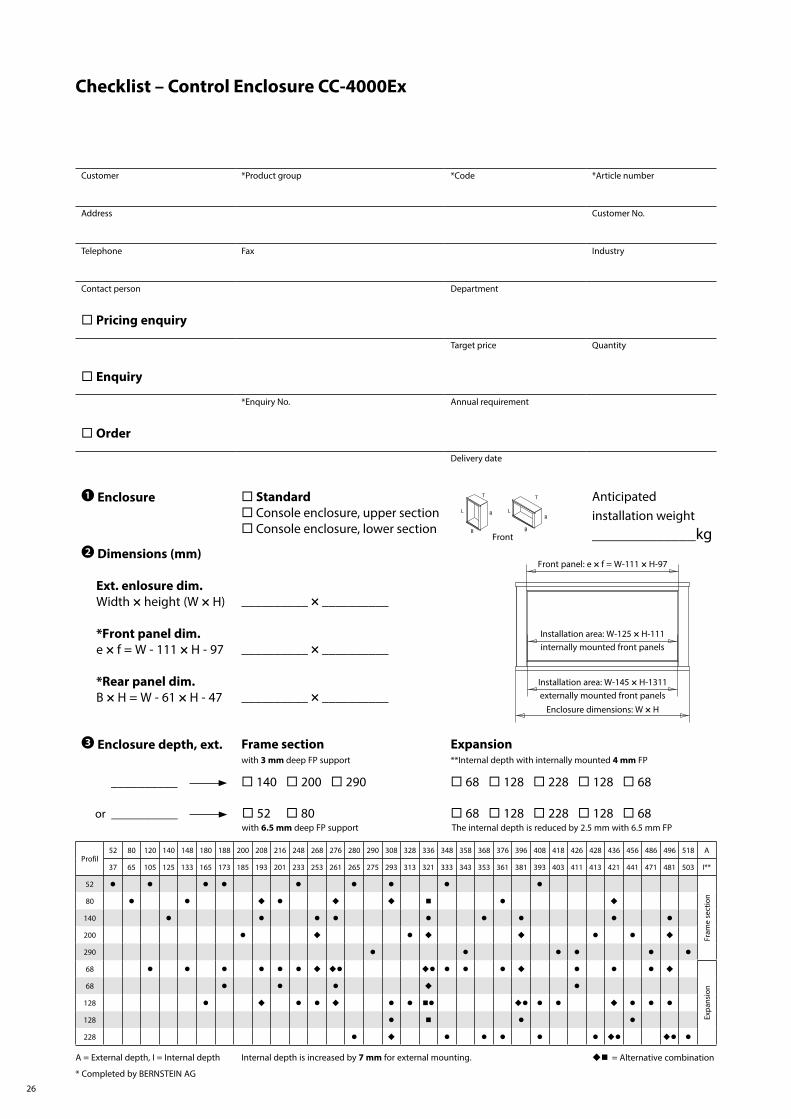
Checklist – Control Enclosure CC-4000Ex
Front panel: e × f = W-111 × H-97
Installation area: W-125 × H-111internally mounted front panels
Installation area: W-145 × H-1311externally mounted front panels
Enclosure dimensions: W × H
Profil52 80 120 140 148 180 188 200 208 216 248 268 276 280 290 308 328 336 348 358 368 376 396 408 418 426 428 436 456 486 496 518 A
37 65 105 125 133 165 173 185 193 201 233 253 261 265 275 293 313 321 333 343 353 361 381 393 403 411 413 421 441 471 481 503 I**
52
Fram
e se
ctio
n
80
140
200
290
68
Expa
nsio
n68
128
128
228
Customer *Product group *Code *Article number
Address Customer No.
Telephone Fax Industry
Contact person Department
Pricing enquiry
Target price Quantity
Enquiry
*Enquiry No. Annual requirement
Order
Delivery date
❶ Enclosure Standard Console enclosure, upper section Console enclosure, lower section B
LR
T
L R
T
B
Anticipated installation weight_____________kg
❷ Dimensions (mm)
Ext. enlosure dim. Width × height (W × H)
*Front panel dim. e × f = W - 111 × H - 97
*Rear panel dim. B × H = W - 61 × H - 47
__________ × __________
__________ × __________
__________ × __________
❸ Enclosure depth, ext. Frame section Expansionwith 3 mm deep FP support **Internal depth with internally mounted 4 mm FP
__________ 140 200 290 68 128 228 128 68
or __________ 52 80 68 128 228 128 68 with 6.5 mm deep FP support The internal depth is reduced by 2.5 mm with 6.5 mm FP
A = External depth, I = Internal depth Internal depth is increased by 7 mm for external mounting. = Alternative combination
* Completed by BERNSTEIN AG
Front

27
T
B
frame section
1st extension
2nd extension
L R
❹ Door mounting (supension system)
2nd extension
2nd extension 1st extension
1st extension Frame section (from 140)Section/fixed rear panel Suspension system position
❺ Front panel (4 mm) Rear panel (3 mm) internally mounted externally mounted externally screw-mounted
❻ Lock
Square (mm) 6 7 8 (Standard)Triangle (mm) 7 8Two-way bit (mm) 3 5T-handle with lock
Customer specification ________________________________________
❼ Preparation for suspension system No TopType of coupling System
Turn/tilt coupling (from section 128) Console connector SL (only section 80) Flange (see system on the right) CS-3000/48 CS-3000 (from section 128) Tilt adapter (from section 200) SS in section ____ 80 (from section 128) Coupling head CC-4000 SS cover, top Spec. preparation to customer specif. SS cover botton Bottom
❽ Surface finishStandard Customer specification
Horizontal sections: RAL 7043, power-coated ___________________________Vertical sections: anodised, natural ___________________________Front panels: anodised, natural ___________________________Rear panels: anodised, natural ___________________________
❾ Climate control data for checking heat dissipation over enclosure surface
____ (Pv) total installed power loss ____ (°C) ambient temperature ____ (°C) max. temperature of installation
❿ Application in zone 2 (gas) Ex nA 2 (gas) Ex i 22 (dust) Ex tc
⓫ Accessories, Remarks______________________________________________________________________________________________________________________________________________________________________________
⓬ General informationProtection class in zone 2 min IP54, in zone 22 min IP64. All built-in and add-on parts for zone 2 must be suitable and certified. All add-on parts are mounted at the factory. Control and operator components of all leading providers are being used.
Door mounting Door mounting

We make safety happen.
We keep safe your visions.
www.bernstein.eu
Contact
International Headquarters BERNSTEIN AGHans-Bernstein-Str. 132457 Porta WestfalicaFon +49 571 793-0Fax +49 571 [email protected]
Denmark BERNSTEIN A/SFon +45 7020 0522Fax +45 7020 [email protected]
Austria BERNSTEIN GmbHFon +43 2256 62070-0Fax +43 2256 [email protected]
Switzerland BERNSTEIN (Schweiz) AGFon +41 44 775 71-71Fax +41 44 775 [email protected]
HungaryBERNSTEIN Kft.Fon +36 1 4342295Fax +36 1 [email protected]
France BERNSTEIN S.A.R.L.Fon +33 1 64 66 32 50Fax +33 1 64 66 10 [email protected]
Italy BERNSTEIN S.r.l.Fon +39 035 4549037Fax +39 035 [email protected]
United Kingdom BERNSTEIN LtdFon +44 1922 744999Fax +44 1922 [email protected]
China BERNSTEIN Safe Solutions(Taicang) Co., Ltd.Fon +86 512 81608180Fax +86 512 [email protected]
700.
0001
.013
. 03
.202
0 . W
e re
serv
e th
e rig
ht to
mak
e ch
ange
s