YOUR COMPLETE TRENCH DRAIN SOURCE - Jay R. Smith Mfg. Co. · JAY R. SMITH MFG. CO. 800.467.6484...
76
SOLUTIONS & MATERIALS YOUR COMPLETE TRENCH DRAIN SOURCE CAST IRON 2700 SERIES CAST IRON 2700 SERIES FIBERGLASS 9812-9872 SERIES FIBERGLASS 9812-9872 SERIES POLYMER CONCRETE 9800 SERIES POLYMER CONCRETE 9800 SERIES POLYPROPYLENE 9900 SERIES POLYPROPYLENE 9900 SERIES STAINLESS STEEL 9660-9679 SERIES STAINLESS STEEL 9660-9679 SERIES
Transcript of YOUR COMPLETE TRENCH DRAIN SOURCE - Jay R. Smith Mfg. Co. · JAY R. SMITH MFG. CO. 800.467.6484...
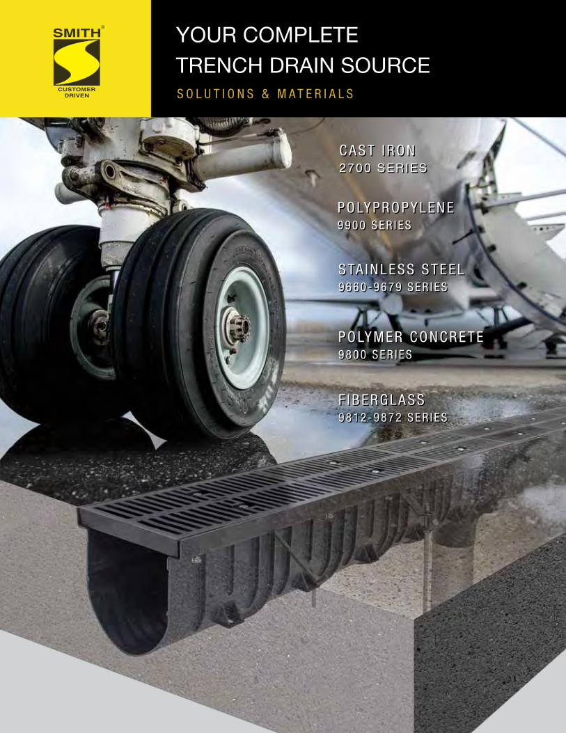
S O L U T I O N S & M A T E R I A L S
YOUR COMPLETETRENCH DRAIN SOURCE
C A S T I R O N 2700 SERIESC A S T I R O N 2700 SERIES
F I B E R G L A S S 9 8 1 2 - 9 8 7 2 S E R I E S
F I B E R G L A S S 9 8 1 2 - 9 8 7 2 S E R I E S
P O LY M E R C O N C R E T E9 8 0 0 S E R I E S
P O LY M E R C O N C R E T E9 8 0 0 S E R I E S
P O LY P R O P Y L E N E 9 9 0 0 S E R I E S
P O LY P R O P Y L E N E 9 9 0 0 S E R I E S
S TA I N L E S S S T E E L 9 6 6 0 - 9 6 7 9 S E R I E S
S TA I N L E S S S T E E L 9 6 6 0 - 9 6 7 9 S E R I E S

INDEX Your COMPLETE Trench Drain Source
Cast Iron Trench Drains2700 – 2900 Series ..........................................................................................1-3Modular Cast Iron - 2700 Series ........................................................................ 2Cast Iron Trench Grating .................................................................................... 3
Polypropylene Trench DrainsEnviro-Flo® II and Zip Trench™ .....................................................................4-186” Wide – 9930 Enviro-Flo® II Series .............................................................4-14Enviro-Flo® II Installation Tips ......................................................................11-12Enviro-Flo® II Accessories ...........................................................................13-146” Wide – 9940 Zip Trench™ Series ............................................................15-1812” Wide – 9960 Zip Trench™ Series ..........................................................19-22Zip Trench™ Accessories ................................................................................. 23Zip Trench™ Grates ......................................................................................... 24Enviro-Flo® II Grates ....................................................................................63-66
Stainless Steel Trench Drains2” to 6” Wide – 9660 – 9679 Series ............................................................23-326” Wide - 9660 Modular Trench Drains .......................................................24-266” Wide - 9665 Series Shallow Modular Trench Drains.................................... 272” Wide - 9666 ADA Linear Shower Drain ........................................................ 282” Wide - 9667 Fine-Line™ ADA Shower Drain ..........................................29-30 9675 Trough/Kettle Drains ................................................................................ 319679 Threshold Drains™ .................................................................................. 32Stainless Steel Grates .................................................................................63-66
Polymer Concrete Trench Drains3” to 14” Wide - 9800 Series .......................................................................32-546” Wide - 9895-9805 Polymer Concrete Trench Drains ..............................35-4010” Wide - 9878-9896 Polymer Concrete Trench Drains ............................41-4614” Wide - 9807-9897 Polymer Concrete Trench Drains ............................47-526” Wide - 9836 Shallow Polymer Concrete Trench Drains ............................... 533” Wide - 9833 Narrow Polymer Concrete Trench Drains ................................ 54Quicklok® and PowerLok® Details .................................................................... 55Oil Separator, Sump Boxes, & Catch Basins ................................................... 56Polymer Concrete Drainage System Accessories ............................................ 57Polymer Concrete Grates ............................................................................63-69
Fiberglass Trench Drains10” to 12” Wide – 9812-9872 Series ...........................................................59-6210” Wide - 9812 High Capacity Fiberglass Trench Drains ..........................59-6010” Wide - 9812 Grates .................................................................................... 69 12” Wide - 9872 High Capacity Fiberglass Trench Drains ..........................61-6212” Wide - 9872 Grates .................................................................................... 61
Grates for 6”, 10”, and 14” Trench Drains .................. 63-69
Trench Drain System Selection and Tips ..................... 70-72
Chemical Resistance Chart ....................Visit www.jrsmith.com
• Listed below are all trademarks of ACO Polymer Products, Inc.: KlassikDrain® QuickLok® PowerDrain® PowerLok® SlabDrain® Channel Slope® ACOWall®
• Listed below are all trademarks of Jay R. Smith Mfg. Co.®: Enviro-Flo® Zip Trench™ Fine-Line® Enviro-Loc® Threshold Drains™

CAST IRON TRENCH DRAINS
Figure Number 2710 - Heavy Duty Modular Cast Iron Trench Drains
Figure Number 2910 - Cast Iron Trench Grating
• Modular trench drains for loading docks, parking garages,
elevated decks
• Heavy duty cast iron construction
• Option: Clamping Collar
Figure Number 2710 Figure Number 2900
1
JAY R. SMITH MFG. CO. 800.467.6484 www.jrsmith.com
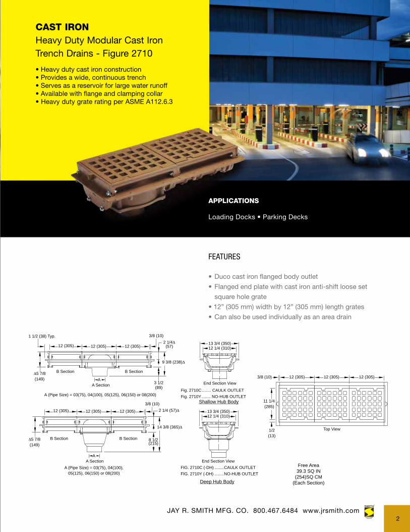
CAST IRONHeavy Duty Modular Cast IronTrench Drains - Figure 2710
APPLICATIONS
Loading Docks • Parking Decks
FEATURES
• Duco cast iron flanged body outlet
• Flanged end plate with cast iron anti-shift loose set
square hole grate
• 12” (305 mm) width by 12” (305 mm) length grates
• Can also be used individually as an area drain
Free Area39.3 SQ IN
(254)SQ CM(Each Section)
Shallow Hub Body
FIG. 2710C (-DH) ........CAULK OUTLETFIG. 2710Y (-DH) ........NO-HUB OUTLET
13 3/4 (350)12 1/4 (310)
End Section View
13 3/4 (350)12 1/4 (310)
Fig. 2710C........ CAULK OUTLETFig. 2710Y........ NO-HUB OUTLET
End Section View12 (305)12 (305)12 (305)3/8 (10)
11 1/4(285)
Top View
A (Pipe Size) = 03(75), 04(100),05(125), 06(150) or 08(200)
14 3/8 (365)Δ
8 1/2(215)
A
12 (305) 12 (305) 12 (305)3/8 (10)
2 1/4 (57)Δ
Δ5 7/8(149)
B Section
A Section
B Section
1/2(13)
2 1/4Δ(57)
9 3/8 (238)Δ
3 1/2(89)
A
1 1/2 (38) Typ.
12 (305) 12 (305) 12 (305)
3/8 (10)
B Section
A Section
B Section
A (Pipe Size) = 03(75), 04(100), 05(125), 06(150) or 08(200)
Δ5 7/8(149)
Deep Hub Body
• Heavy duty cast iron construction• Provides a wide, continuous trench• Serves as a reservoir for large water runoff• Available with flange and clamping collar• Heavy duty grate rating per ASME A112.6.3
2
CAST IRON TRENCH DRAINS

CAST IRONCast Iron Trench Grating Figure 2900
APPLICATIONS
Pedestrian Walkways • Outdoor Shopping CentersPromenade Areas
FEATURES
• Duco Cast Iron grate with steel frame
• Grate and frame provide large free drainage area
2910, 2920 - Light duty, designed for pedestrian
traffic only
2940, 2950 - Medium duty, designed for pedestrian
traffic only
2970, 2980 - Heavy duty, designed for heavy trucks
and traffic. 2970-M ductile iron slotted
grate is H-20 rated
12(305)
12(305)
12(305)
12(305)
1 1/4 (32)
1 (25)
12(305)
12 1/2(320)
24 1/2 (620)
Add 12" (305)For Each
Additional Grate
1 1/4 (32)
1 (25)
24 1/2 (620)
24 1/2(620)
24(610)
Add 12" (305)For Each
Additional Grate
24 (610) 24 (610)
48 1/2 (1232)
12 1/2(320)
Add 24" (610) ForEach
Additional Grate2 (51)
12 1/2 (320)
12 (305)
12(305)
12(305)
24 1/2 (620)
24 1/2(620)
Add 12" (305) ForEach
Additional Grate
Fig. 2970 . . . 1 Grate Only - 12 (305) x 24 (610)Fig. 2971 . . . 1 Grate with Frame - 12 1/2 (320) x 24 1/2 (620)Fig. 2972 . . . 2 Grates with Frame - 12 1/2 (320) x 48 1/2 (1232)
Fig. 2982 . . . 2 Grates with Frame - 24 1/2 (620) x 24 1/2 (620)Fig. 2983 . . . 3 Grates with Frame - 24 1/2 (620) x 36 1/2 (925)Fig. 2984 . . . 4 Grates with Frame - 24 1/2 (620) x 48 1/2 (1232)
26.77(680mm)
23.86(606mm)
5.51(140mm) x1.18(30mm) Slot(10 Places)
4.92(125mm) x1.18(30mm) Slot(18 Places)
4.33(110mm) x1.18(30mm) Slot(12 Places)
H20 Ductile Iron Grate Detail
12 1/2(320)
24 (610) 24 (610)
48 1/2 (1232)
Add 24" (610) ForEach
Additional Grate1 1/4 (32)
12 1/2 (320)
12 (305)
12(305)
12(305)
24 1/2 (620)
24 1/2(620)
Add 12" (305) ForEach
Additional Grate
Fig. 2940 . . . 1 Grate Only - 12 (305) x 24 (610)Fig. 2941 . . . 1 Grate with Frame - 12 1/2 (324) x 24 1/2 (620)Fig. 2942 . . . 2 Grates with Frame - 12 1/2 (320) x 48 1/2 (1232)
Fig. 2952 . . . 2 Grates with Frame - 24 1/2 (620) x 24 1/2 (620)Fig. 2953 . . . 3 Grates with Frame - 24 1/2 (620) x 36 1/2 (925)Fig. 2954 . . . 4 Grates with Frame - 24 1/2 (620) x 48 1/2 (1232)
Figure 2910
Figure 2940
Figure 2970
JAY R. SMITH MFG. CO. 800.467.6484 www.jrsmith.com
• Designed for pedestrian traffic• Frame and grate provide large free drainage area• Continuous grate sections in overall lengths provide maximum versatility• Heavy duty grate rating per ASME A112.6.3
3

POLYPROPYLENE TRENCH DRAINS
6” AND 12” WIDE - 9930 - 9960 SERIES
6” Enviro-Flo® IIFigure Number 9930Load Class A, B, C
6” Enviro-Flo® II Figure Number 9931
Load Class A - E
6” Zip Trench™Figure Number 9940
Load class A - E
Figure Number 9930 - 6” Wide Enviro-Flo® II Polypropylene Trench Drains
Figure Number 9931 - 6” Wide Enviro-Flo® II Polypropylene Trench Drains with
Steel Frame System for Extra Heavy Duty Applications
Figure Number 9940 - 6” Wide Zip Trench™ Polypropylene Trench Drains
Figure Number 9960 - 12” Wide Zip Trench™ Polypropylene Trench Drains
• Lightweight, interlocking polypropylene channels
• Durable and versatile
• Ideal for heavy duty applications
• Superior chemical and UV resistance
JAY R. SMITH MFG. CO. 800.467.6484 www.jrsmith.com4
12 “ Zip Trench™Figure Number 9960
Load class A - E

POLYPROPYLENE DRAIN SYSTEM 6” Wide Enviro-Flo® II Trench Drains Figure 9930
APPLICATIONS
Ball Parks • Stadiums • Chemical Processing Plants Food and Beverage • Breweries • Swimming Pools Driveways • Kitchens • Greenhouses
FEATURES
• Utilizes the QuickLok® grate feature that allows the
grating to be secured and removed without bolting
or screwing to the channel easily
• Built-in slope of 0.6% and radiused bottom
• Load Classes A-C depending on grate selection
• Heavy Duty EN1433 Load Class C:
56,000 lbs - 1,162 psi
• Handles up to Load Class C pneumatic tire
with the proper grate selection
• Integral rebar support
REGULARLY FURNISHED:1 Meter (3.28') 100% PolypropylenePost Industrial Recycled Material withU.V. Inhibitors. Channel of InterlockingDesign with a Built-inSlope of .06%with Radiused Bottom. Supplied withSecured Grate.
65'-7 1/2" (20 meters) Sloped
4" Horizontal Outlet CapFits Channels #10-20N)
Non-SlopingNeutral Channels
*Catch Basin9935-20
1 2 3 4 5 6 7 8 9 10 11 12 13 14 15 16 17 18 19 20
1N 2N 3N 4N 5N 6N 7N 8N 9N 10N 11N 12N 13N 14N 15N 16N 17N 18N 19N 20N
65'-7 1/2" (20 meters) Non-Sloped
Universal Closing End CapSpecify Shallow or Deep End
Note: Dimensions in Parentheses are in mm.
*Note: If Catch Basin is Specified For Any Other Channel Except For the #20 Channel, a Shim Must be Ordered, P/N: 9930-ES
Note: This Trench Drain System is Designed for "On Grade Applications Only" as There are No Provisions for a Flashing Flange or Flashing Clamp
**Note: All 1 Meter Long Sloped and Neutral Channels Have a Molded 4"(111) No-Hub Bottom Connection.
Integral RebarSupport (4 Per Channel)
8.00"(203)5.25"(133)
3.75"(95)
4.00"(102)-9.25"(235) Top to Bottom
of Channel
ENLARGED END VIEW
1.50(38)
9930 Enviro Flo II Trench Drain SystemR
Quick-Lok®
Lock Bar
ClosingEnd Cap
4" and 6" No-Hub Connection
(1/2 meter)19.68"
ShallowEnd Cap
4” No-Hub HorizontalOutlet Cap
9930 Trench Drains with Catch Basin
QuickLok® is a registered trademark of ACO Polymer Products, Inc.
• Lightweight, interlocking polypropylene channels are ideal for heavy duty applications• Excellent chemical resistance• Superior UV resistance• Bottom outlet on every section• Temperature rating up to 180˚ F• Load Class A - C
JAY R. SMITH MFG. CO. 800.467.6484 www.jrsmith.com
Note: This trench drain system is designed for “on grade applications only” as there are no provisions for a flashing flange or flashing clamp. Please contact Jay R. Smith Trench Drain team at 800-467-6484 for assistance when flashing flange or flashing are required.
5

Enviro-Flo® II Polypropylene Trench Drains - Figure 9930
REGULARLY FURNISHED:1 Meter (3.28') 100% PolypropylenePost Industrial Recycled Material withU.V. Inhibitors. Channel of InterlockingDesign with a Built-inSlope of .06%with Radiused Bottom. Supplied withSecured Grate.
65'-7 1/2" (20 meters) Sloped
4" Horizontal Outlet CapFits Channels #10-20N)
Non-SlopingNeutral Channels
*Catch Basin9935-20
1 2 3 4 5 6 7 8 9 10 11 12 13 14 15 16 17 18 19 20
1N 2N 3N 4N 5N 6N 7N 8N 9N 10N 11N 12N 13N 14N 15N 16N 17N 18N 19N 20N
65'-7 1/2" (20 meters) Non-Sloped
Universal Closing End CapSpecify Shallow or Deep End
Note: Dimensions in Parentheses are in mm.
*Note: If Catch Basin is Specified For Any Other Channel Except For the #20 Channel, a Shim Must be Ordered, P/N: 9930-ES
Note: This Trench Drain System is Designed for "On Grade Applications Only" as There are No Provisions for a Flashing Flange or Flashing Clamp
**Note: All 1 Meter Long Sloped and Neutral Channels Have a Molded 4"(111) No-Hub Bottom Connection.
Integral RebarSupport (4 Per Channel)
8.00"(203)5.25"(133)
3.75"(95)
4.00"(102)-9.25"(235) Top to Bottom
of Channel
ENLARGED END VIEW
1.50(38)
HYDRAULIC CAPACITY AND TRENCH DEPTH 9930 SYSTEMChannel Number
Shallow End Depth Deep End DepthSlope
Single Channel Weight Lbs.Inch mm Inch mm Est. CFS Est. GPM
9930-1 4.00 102 4.38 111 0.6% 0.29 130 6.509930-1N 4.38 111 4.38 111 0.0% 0.29 130 6.509930-2 4.38 111 4.62 117 0.6% 0.31 139 6.609930-2N 4.62 117 4.62 117 0.0% 0.31 139 6.609930-3 4.62 117 4.88 124 0.6% 0.34 153 6.809930-3N 4.88 124 4.88 124 0.0% 0.34 153 6.809930-4 4.88 124 5.12 130 0.6% 0.36 162 6.909930-4N 5.12 130 5.12 130 0.0% 0.36 162 6.909930-5 5.12 130 5.38 137 0.6% 0.39 175 7.009930-5N 5.38 137 5.38 137 0.0% 0.39 175 7.009930-6 5.38 137 5.63 143 0.6% 0.42 189 7.209930-6N 5.63 143 5.63 143 0.0% 0.42 189 7.209930-7 5.63 143 5.88 149 0.6% 0.45 202 7.409930-7N 5.88 149 5.88 149 0.0% 0.45 202 7.409930-8 5.88 149 6.12 155 0.6% 0.47 211 7.609930-8N 6.12 155 6.12 155 0.0% 0.47 211 7.609930-9 6.12 155 6.38 162 0.6% 0.49 220 7.609930-9N 6.38 162 6.38 162 0.0% 0.49 220 7.609930-10 6.38 162 6.62 168 0.6% 0.53 238 7.809930-10N 6.62 168 6.62 168 0.0% 0.53 238 7.809930-11 6.62 168 6.68 170 0.6% 0.56 251 8.009930-11N 6.68 170 6.68 170 0.0% 0.56 251 8.009930-12 6.68 170 7.12 181 0.6% 0.58 261 8.009930-12N 7.12 181 7.12 181 0.0% 0.58 261 8.009930-13 7.12 181 7.38 187 0.6% 0.62 274 8.409930-13N 7.38 187 7.38 187 0.0% 0.62 274 8.409930-14 7.38 187 7.62 194 0.6% 0.64 287 8.409930-14N 7.62 194 7.62 194 0.0% 0.64 287 8.409930-15 7.62 194 7.88 200 0.6% 0.67 301 8.609930-15N 7.88 200 7.88 200 0.0% 0.67 301 8.609930-16 7.88 200 8.12 206 0.6% 0.7 314 8.809930-16N 8.12 206 8.12 206 0.0% 0.7 314 8.809930-17 8.12 206 8.38 213 0.6% 0.73 328 8.809930-17N 8.38 213 8.38 213 0.0% 0.73 328 8.809930-18 8.38 213 8.62 219 0.6% 0.76 341 9.009930-18N 8.62 219 8.62 219 0.0% 0.76 341 9.009930-19 8.62 219 8.88 226 0.6% 0.79 355 9.209930-19N 8.88 226 8.88 226 0.0% 0.79 355 9.209930-20 8.88 226 9.12 232 0.6% 0.82 368 9.409930-20N 9.12 232 9.12 232 0.0% 0.82 368 9.40
Note: Channel flow rates based on channels less grates and open ended.6
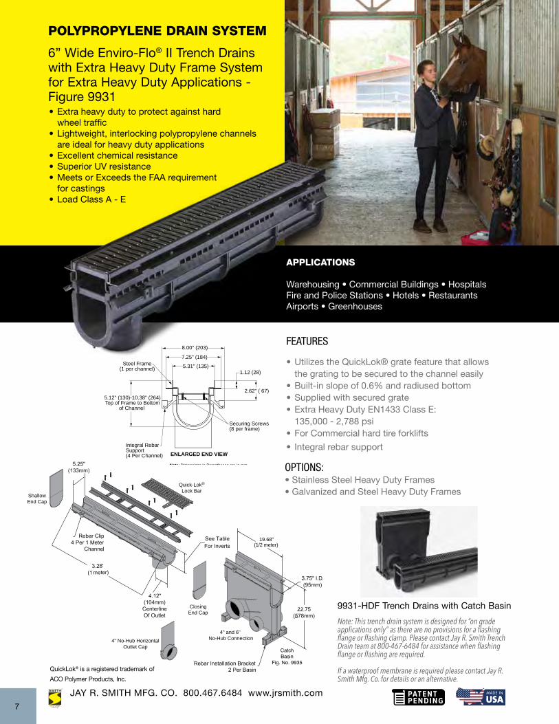
POLYPROPYLENE DRAIN SYSTEM 6” Wide Enviro-Flo® II Trench Drains with Extra Heavy Duty Frame System for Extra Heavy Duty Applications - Figure 9931
APPLICATIONS
Warehousing • Commercial Buildings • Hospitals Fire and Police Stations • Hotels • Restaurants Airports • Greenhouses
FEATURES
• Utilizes the QuickLok® grate feature that allows the grating to be secured to the channel easily• Built-in slope of 0.6% and radiused bottom• Supplied with secured grate• Extra Heavy Duty EN1433 Class E: 135,000 - 2,788 psi • For Commercial hard tire forklifts
• Integral rebar support
Note: Dimensions in Parentheses are in mm.
*Note: If Catch Basin is Specified For Any Other Channel Except For the #20 Channel, a Shim Must be Ordered, P/N: 9930-ES
Note: This Trench Drain System is Designed for "On Grade Applications Only" as There are No Provisions for a Flashing Flange or Flashing Clamp
**Note: All 1 Meter Long Sloped and Neutral Channels Have a Molded 4"(111) No-Hub Bottom Connection.
5.12" (130)-10.38" (264)Top of Frame to Bottom
of Channel
ENLARGED END VIEWIntegral RebarSupport(4 Per Channel)
8.00" (203)
Steel Frame(1 per channel)
Securing Screws(8 per frame)
5.31" (135)7.25" (184)
1.12 (28)
2.62" ( 67)
9931-HDF Trench Drains with Catch Basin
• Extra heavy duty to protect against hard wheel traffic• Lightweight, interlocking polypropylene channels are ideal for heavy duty applications• Excellent chemical resistance• Superior UV resistance• Meets or Exceeds the FAA requirement for castings• Load Class A - E
Quick-Lok®
Lock Bar
ClosingEnd Cap
4" and 6" No-Hub Connection
(1/2 meter)19.68"
ShallowEnd Cap
4” No-Hub HorizontalOutlet Cap
JAY R. SMITH MFG. CO. 800.467.6484 www.jrsmith.com
Note: This trench drain system is designed for “on grade applications only” as there are no provisions for a flashing flange or flashing clamp. Please contact Jay R. Smith Trench Drain team at 800-467-6484 for assistance when flashing flange or flashing are required.
If a waterproof membrane is required please contact Jay R. Smith Mfg. Co. for details or an alternative.
OPTIONS: • Stainless Steel Heavy Duty Frames • Galvanized and Steel Heavy Duty Frames
QuickLok® is a registered trademark of
ACO Polymer Products, Inc.
7

FEATURES
• Utilizes the QuickLok® grate feature that allows the grating to be secured to the channel easily• Built-in slope of 0.6% and radiused bottom• Supplied with secured grate• Extra Heavy Duty EN1433 Class E: 135,000 - 2,788 psi • For Commercial hard tire forklifts
• Integral rebar support
FUNCTION: Used in all surface drainage, may be assembled in any length utilizing ductile iron frame system that isrecommended for situations requiring an extra heavy duty rating to protect against hard wheel traffic, impact of steel containers,struts and metal wheels.
65'-7 1/2" (20 meters) Sloped
4" Horizontal Outlet CapFits Channels #10-20N)
Non-SlopingNeutral Channels
*Catch Basin9936-20
1 2 3 4 5 6 7 8 9 10 11 12 13 14 15 16 17 18 19 20
1N 2N 3N 4N 5N 6N 7N 8N 9N 10N 11N 12N 13N 14N 15N 16N 17N 18N 19N 20N
65'-7 1/2" (20 meters) Non-Sloped
Universal Closing End CapSpecify Shallow or Deep End
Note: Dimensions in Parentheses are in mm.
*Note: If Catch Basin is Specified For Any Other Channel Except For the #20 Channel, a Shim Must be Ordered, P/N: 9930-ES
Note: This Trench Drain System is Designed for "On Grade Applications Only" as There are No Provisions for a Flashing Flange or Flashing Clamp
**Note: All 1 Meter Long Sloped and Neutral Channels Have a Molded 4"(111) No-Hub Bottom Connection.
2.62"(67)
ENLARGEDEND VIEW
5.12"(130)-10.38"(264) Top of Frame to Bottom
of Channel
8.00"(203)6.12"(156)4.88"(124)
3.75"(95)
Integral RebarSupport
(4 Per Channel) Concrete Anchors (8)Regularly Furnishedper 1 meter Channel
HYDRAULIC CAPACITY AND DEEP END DEPTHS 9931-HDF SYSTEMChannel Number
Shallow End Invert Deep End InvertSlope
Single Channel Weight Lbs.Inch mm Inch mm Est. CFS Est. GPM
9931-1 5.12 130 5.50 140 0.6% 0.29 130 23.029931-1N 5.50 140 5.50 140 0.0% 0.29 130 23.029931-2 5.50 140 5.75 146 0.6% 0.31 139 23.129931-2N 5.75 146 5.75 146 0.0% 0.31 139 23.129931-3 5.75 146 6.00 152 0.6% 0.34 153 23.329931-3N 6.00 152 6.00 152 0.0% 0.34 153 23.329931-4 6.00 152 6.25 159 0.6% 0.36 162 23.429931-4N 6.25 159 6.25 159 0.0% 0.36 162 23.429931-5 6.25 159 6.50 165 0.6% 0.39 175 23.529931-5N 6.50 165 6.50 165 0.0% 0.39 175 23.529931-6 6.50 165 6.75 171 0.6% 0.42 189 23.729931-6N 6.75 171 6.75 171 0.0% 0.42 189 23.729931-7 6.75 171 7.00 178 0.6% 0.45 202 23.929931-7N 7.00 178 7.00 178 0.0% 0.45 202 23.929931-8 7.00 178 7.25 184 0.6% 0.47 211 24.329931-8N 7.25 184 7.25 184 0.0% 0.47 211 24.329931-9 7.25 184 7.50 191 0.6% 0.49 220 24.329931-9N 7.50 191 7.50 191 0.0% 0.49 220 24.329931-10 7.50 191 7.75 197 0.6% 0.53 238 24.329931-10N 7.75 197 7.75 197 0.0% 0.53 238 24.329931-11 7.75 197 8.00 203 0.6% 0.56 251 24.529931-11N 8.00 203 8.00 203 0.0% 0.56 251 24.529931-12 8.00 203 8.25 210 0.6% 0.58 261 24.529931-12N 8.25 210 8.25 210 0.0% 0.58 261 24.529931-13 8.25 210 8.50 216 0.6% 0.62 274 24.929931-13N 8.50 216 8.50 216 0.0% 0.62 274 24.929931-14 8.50 216 8.75 222 0.6% 0.64 287 24.929931-14N 8.75 222 8.75 222 0.0% 0.64 287 24.929931-15 8.75 222 9.00 229 0.6% 0.67 301 25.129931-15N 9.00 229 9.00 229 0.0% 0.67 301 25.129931-16 9.00 229 9.25 235 0.6% 0.7 314 25.329931-16N 9.25 235 9.25 235 0.0% 0.7 314 25.329931-17 9.25 235 9.50 241 0.6% 0.73 328 25.329931-17N 9.50 241 9.50 241 0.0% 0.73 328 25.329931-18 9.50 241 9.75 248 0.6% 0.76 341 25.529931-18N 9.75 248 9.75 248 0.0% 0.76 341 25.529931-19 9.75 248 10.00 254 0.6% 0.79 355 25.729931-19N 10.00 254 10.00 254 0.0% 0.79 355 25.729931-20 10.00 254 10.25 260 0.6% 0.82 368 25.929931-20N 10.25 260 10.25 260 0.0% 0.82 368 25.92
Note: Channel flow rates based on channels less grates and open ended.
6” Wide Enviro-Flo® II Polypropylene Trench Drains with Extra Heavy Duty Frame System - Figure 9931
8

Enviro-Flo® II Trench DrainsFeatures and Benefits Figure Number 9930 and 9931
Enviro-Flo® II – The Contractor Friendly System that Replaces Cast-in-Place Trench Drains
System Features• Each section has a 4” molded no-hub bottom outlet connection• Each channel is identified with flow arrow and sequence numbers• Each channel has angular full length anchoring ribs• Each channel is shipped with a removable factory insert board constructed from post-industrial recycled material that functions as a stabilizer and debris guard• Horizontal outlet cap available• Mechanical interlocking end caps
Lightweight–Easy to Handle• 98% recycled polypropylene with 2% carbon black• Reduces installation costs in every aspect• Easy field modification: cut, drill, machine, weld• Superior chemical resistance• Durable—non-breakable• Handles up to 180˚ F
Enviro-Loc®
• Mechanical interlocking joint• Alignment integrity maintained• With proper sealant, provides a watertight connection
Integral Rebar Mount
Vertical OutletThe vertical outlet attachesto the Enviro-Flo® II accessory rail to create an outletanywhere on the channel.
JAY R. SMITH MFG. CO. 800.467.6484 www.jrsmith.com9

Enviro-Flo® II Trench DrainsFeatures and Benefits Figure Number 9930 and 9931
Presloped Channels• 1 meter (3.28 feet) channel sections speed installation• Presloped (.6%) radius channels• Smooth, uniform interior delivers best hydraulic performance
Locking Grates• Complete selection to meet all requirements• Positive lockdown function means grates won’t wobble• No frames required to meet Load Class C Heavy Duty EN1433 up to 56,000 lbs. 1,162 psi• Ease of Maintenance
Rante Arrow MountProvides vertical and horizontal adjustments for quick and easy elevation set.
Features for Enviro-Flo® II• 20 sloping and 20 neutral channels• Mounting System: Integral rebar clips or the Rante Arrow offer flexible installation options• Secure Tongue & Groove Connections: Tongue and groove connectors retain more sealant for a more uniform joint• Flexible Installation: Choose outlet location, create miter and tee connections with adapters, and shorten channels in the field
Flow Direction Arrow
NumberedThe sequence number is moldedon the hub
JAY R. SMITH MFG. CO. 800.467.6484 www.jrsmith.com10

JAY R. SMITH MFG. CO. 800.467.6484 www.jrsmith.comJAY R. SMITH MFG. CO. 800.467.6484 www.jrsmith.com
ENVIRO-FLO® II INSTALLATION TIPS Integral Rebar Mounting System
The Jay R. Smith Mfg. Co.® Enviro-Flo® II Systems with Enviro-Loc® joints are easy to install using the Integral Rebar Clips or Rante Arrow.
Always begin install at the outlet end.
See structural drawings for reinforcing of the concrete and location of expansion joints
For rebar installation, simply align male and female ends of channels and slide together as illustrated in photos 2 and 3.
After making the Enviro-Loc® connection, ensure that the channels are securely connected and aligned correctly, then insert rebar into the integral rebar clips and secure into the ground.
After securing the channel with rebar, span the channel joint with the factory furnished recycled boardinsert to protect channel grate recess, prevent debris from entering channel section and maintain proper channel and grate alignment.
2. Align male and female ends of the channels.
3. Slide channels together. Ensure that channels are securely connected and correctly aligned.
1. If 9935 catch basin is required, insert channel on one end as shown above.
4. Secure channel into the ground with rebar using integral rebar clips.
11
JAY R. SMITH MFG. CO. 800.467.6484 www.jrsmith.com
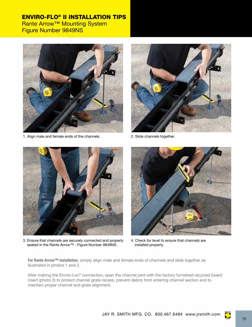
ENVIRO-FLO® II INSTALLATION TIPS Rante Arrow™ Mounting System Figure Number 9849NS
1. Align male and female ends of the channels. 2. Slide channels together.
3. Ensure that channels are securely connected and properly seated in the Rante Arrow™ - Figure Number 9849NS.
4. Check for level to ensure that channels are installed properly.
For Rante Arrow™ installation, simply align male and female ends of channels and slide together asillustrated in photos 1 and 2.
After making the Enviro-Loc® connection, span the channel joint with the factory furnished recycled board insert (photo 3) to protect channel grate recess, prevent debris from entering channel section and tomaintain proper channel and grate alignment.
12
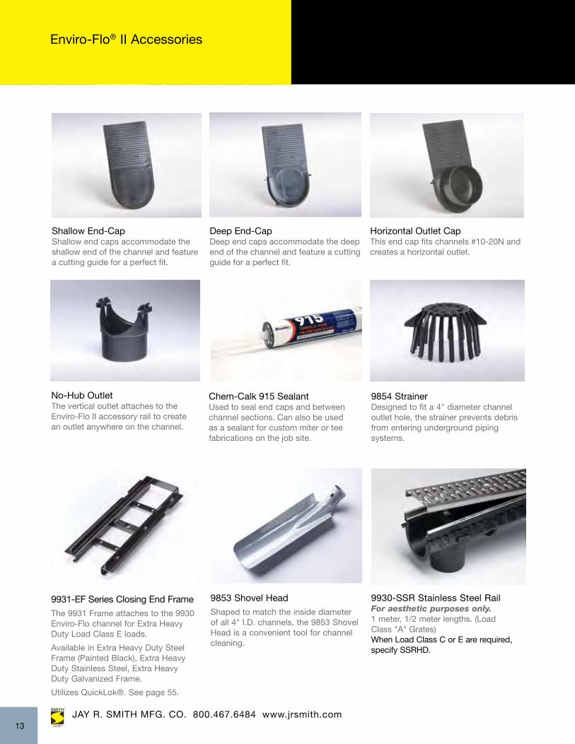
9930-SSR Stainless Steel RailFor aesthetic purposes only.1 meter, 1/2 meter lengths. (Load Class "A" Grates)When Load Class C or E are required, specify SSRHD.
9853 Shovel Head
Shaped to match the inside diameter of all 4" I.D. channels, the 9853 Shovel Head is a convenient tool for channel cleaning.
9854 Strainer Designed to fit a 4" diameter channel outlet hole, the strainer prevents debris from entering underground piping systems.
9931-EF Series Closing End Frame The 9931 Frame attaches to the 9930 Enviro-Flo channel for Extra Heavy Duty Load Class E loads.
Available in Extra Heavy Duty Steel Frame (Painted Black), Extra Heavy Duty Stainless Steel, Extra Heavy Duty Galvanized Frame.
Utilizes QuickLok®. See page 55.
JAY R. SMITH MFG. CO. 800.467.6484 www.jrsmith.comJAY R. SMITH MFG. CO. 800.467.6484 www.jrsmith.com
Chem-Calk 915 Sealant Used to seal end caps and betweenchannel sections. Can also be usedas a sealant for custom miter or tee fabrications on the job site.
Horizontal Outlet CapThis end cap fits channels #10-20N and creates a horizontal outlet.
Shallow End-CapShallow end caps accommodate the shallow end of the channel and feature a cutting guide for a perfect fit.
Deep End-CapDeep end caps accommodate the deep end of the channel and feature a cutting guide for a perfect fit.
No-Hub OutletThe vertical outlet attaches to the Enviro-Flo II accessory rail to create an outlet anywhere on the channel.
Enviro-Flo® II Accessories
13

JAY R. SMITH MFG. CO. 800.467.6484 www.jrsmith.com
Enviro-Flo® II Accessories andSystem Customizations
Custom Factory FabricationsFactory fabrications are availableupon request and are designed and manufactured to meet your specific requirements.
Tee ConnectionThe tee connection allows contractors to make quick and easy tee connections inthe field.
Male CouplingThe male coupling allows two malechannel ends to be joined together,offering contractors greater flexibilityto make adjustments in the field.
Allows for a design that incorporates the high point in the middle of run.
Enviro-Flo® II Systems Customizations
9849NS Rante-Arrow
The 9849NS Rante-Arrow is designed for use with the 9930 and 9931 systems. The 9849NS Rante-Arrow firmly anchors the channel system in most sub-base conditions, eliminating flotation and allowing for a monolithic pour. Provides vertical and horizontal adjustments for quick and accurate elevation set.
The 9935 and 9936 Series Catch Basins are the same width as the 9930 or 9931 Channels. They can be used with any style 9930 or 9931 frame and grate options. Trash bucket in plastic material is available for easy removal of debris. Reference pages 65 and 66 for complete grate information.
9935/9936 Catch Basins with Trash Bucket
14

6” Wide Trench with Drains Extra Heavy Duty Frame- Figure 9940
JAY R. SMITH MFG. CO. 800.467.6484 www.jrsmith.com
ZIP TRENCH™ FEATURES:
• Fast, long, pre-assembled runs shipped from factory: 9’-10” (3 meter) long channels• 16 Channels - 12 sloping channels and 4 neutral channels from a depth of 4.81” to 13.81”• Built-in slope .6% • See grates on pages 65 - 66
trenchip
• 0-60 feet in 6 sections• Lighter weight and faster to install than polymer concrete• Better chemical resistance than polyethylene• Temperature rating of 180 degrees vs 140 degrees F with polyethylene• Load Class A - E
POLYPROPYLENE DRAIN SYSTEM
APPLICATIONS Industrial Plants • Warehousing • Pedestrian Walkways Fire and Police Stations • Commercial and Industrial Driveway Entrances • Petrochemical Processing PlantsGreenhouses
JAY R. SMITH MFG. CO. 800.467.6484 www.jrsmith.com15
Universal Closing End CapsSpecify Shallow (-ES) or Deep End (-ED)
ENLARGED END VIEW
1 2 3 4 5 6 7 8 9 10 11 12
3N 6N 9N 12N
9'-10 1/8" (3000)
SIDE VIEW
TOP VIEW
4 13/16" (122) -13 13/16" (351)
29 9/16" (750)59 1/2" (1500)29 9/16" (750)
Bottom Outlet 4" DIA
Female End Male End
Welded Installation DeviceFor Rebar Support(4 Per Frame)(Rebar Posts By Others)
5 1/8"(130)
12 7/8" (327)
3 5/8"(92)
13/16" (21)
118'-1 11/16" (36 meters) Sloped
Non-sloping3 MeterNeutral Channels4" Horizontal Outlet End Cap-H4(Fits Channels #4-12N)

JAY R. SMITH MFG. CO. 800.467.6484 www.jrsmith.com37
6” Wide Trench Drain System Figure 9940
trenchip
Note: This trench drain system is designed for “on grade applications only” as there are no provisions for a flashing flange or flashing clamp. Please contact Jay R. Smith Trench Drain team at 800-467-6484 for assistance when flashing flange or flashing are required.
If a waterproof membrane is required please contact Jay R. Smith Mfg. Co. for details or an alternative.
16
REV. DATE DESCRIPTION BY CKD. BY
WEIGHTPOUNDS
VOLUMECUBIC FEET
FIGURE NUMBER
LOCATION
FIG
UR
EN
UM
BER
DIM
ENSI
ON
S AR
E SU
BJEC
T TO
MAN
UFA
CTU
RER
S TO
LER
ANC
E AN
D C
HAN
GE
WIT
HO
UT
NO
TIC
EW
E C
AN A
SSU
ME
NO
RES
PON
SIBI
LITY
FO
R U
SE O
F SU
PER
SED
ED O
R V
OID
DAT
A
DR
AWN
BY:
CH
ECKE
D B
Y:AP
PRO
VED
BY:
SCAL
E:SI
ZE AD
RAW
ING
NU
MBE
RN
ON
ED
ATE:
JAY R.SMITH MFG. CO.®
MEMBER OF MORRIS GROUP INTERNATIONALPOST OFFICE BOX 3237MONTGOMERY, ALABAMA 36109-0237 (USA)TEL: 334-277-8520 FAX: 334-272-7396 www.jrsmith.com
CUSTOMERDRIVEN
SMITH®
MEMBER OF:
®
ASPE®
SANITARY
EN G IN E E RINGPrevention Rather Than Cure
SINCE 1926
TBW
CL
S994
0BS
7-22
-14
JM99
40B
S
9940BSWARNING: Cancer and Reproductive Harm - www.P65Warnings.ca.gov ADVERTENCIA: Cáncer y daño reproductivo - www.P65Warnings.ca.gov
9940 6" WIDE ZIP TRENCH
Channel Number
Deep End Invert Inch mm
Slope Single ChannelEst. CFS Est. GPM
Weight Lbs.Frame + Channel
0.6% .29 130 38.00 9940-2
141
.31 139 39.00 9940-3
5.56
160 .34 153 40.00
9940-4
6.31 179
.36 162 41.00 9940-5
7.06
198 .39 175 42.00
9940-6
7.81 267
.42 189 44.00
9940-7
8.56
.45 202 45.00 9940-8
256
.47 211 47.00
9940-6N .47 211 44.00
9940-9
10.06 275
.49 220 49.00 9940-9N .49 220 51.00 9940-10
10.81
313 .53 238 51.50
9940-11
12.31
.56 251 51.00 9940-12 .58 261 51.00 9940-12N
351 .58 261 51.00
13.81
9940-1
0.0%
0.0%
0.0%
HYDRAULIC CAPACITY SHALLOW / DEEP END DEPTHS 9940 SYSTEM
Note: Channel flow rates based on channels less grates and open ended.
*Supplied with Quick-lok® securing device regularly furnished
9940-3N .47 211 40.00 0.0%
0.6% 0.6% 0.6% 0.6% 0.6% 0.6% 0.6% 0.6% 0.6% 0.6% 0.6%
179 7.06
236
9.31
236 9.31
294
11.56
294 11.56
332
13.06
351 13.81
Shallow End Invert Inch mm
122 4.81
141 5.56
179
7.06
179 7.06
198 7.81
236
9.31 256
10.06
294
11.56
351
13.81
160
6.31
236
8.56 267
9.31 275
10.81
294 11.56
313
12.31
332 13.06
**********
****
****
*
Light Duty DIN 19580 Load Class A:3500 lbs - 70 psi. For pedestrian,wheelchair and bicycle traffic.
9870-410-GP - 1/4 dia perforated galv. steelgrate (28.30 sq. in.)9870-420-G - 3 1/4 x 3/8 slotted galv. steel grate(35.20 sq. in.)9870-451-SSPA - 1/4 dia perforated stainless steelgrate (28.30 sq. in.)9870-494-PADAB - 1 3/4 x 5/16 longitudinal slotblack polypropylene grate (27.40 sq. in.)9870-494-PADAG - 1 3/4 x 5/16 longitudinal slotgray polypropylene grate (27.40 sq. in.)
Medium Duty DIN 19580 Load Class B:28100 lbs - 581 psi. For light vehicle traffic.
9870-447-SSADA - 13/16 x 3/16 longitudinalstainless steel slot bar grate (58.40 sq. in.)
Heavy Duty DIN 19580 Load Class C:56,000 lbs - 1,162 psi. For commercialpneumatic tire traffic patterns, forklifts andtractor trailers.
9870-405-GM - 13/16 x 1/2 longitudinal galv. steelslot bar grate (121.10 sq. in.)9870-411-GPHD - 1/4 dia perforated galv. steelgrate (28.30 sq. in.)9870-425-GHD- 3 1/4 x 3/8 slotted galv. steel grate(35.20 sq. in.)9870-430-SSM - 13/16 x 1/2 longitudinal stainlesssteel slot bar grate (121.10 sq. in.)9870-455-SSHD - 3 1/4 x 3/8 slotted stainless steelgrate (42.60 sq. in.)9870-465-SSP- 1/4 dia perforated stainless steelgrate (28.30 sq. in.)9870-479-MD - Mosaic pattern ductile iron grate(19.50 sq. in.)9870-481-ID - Iron Decorative pattern ductile irongrate (19.00 sq. in.)9870-492-RC - 1 1/2 x 13/16 slotted resin compositegrate (16.30 sq. in.)
Extra Heavy Duty, DIN 19580 Class E:135,000 lbs - 2,788 psi. For commercial solid tiretraffic patterns, forklifts and impacts from steelstruts or metal wheels.
9870-435-GHDE - 3 1/4 x 3/8 slotted galv. steelgrate (42.60 sq. in.)9870-461-M - 3 15/16 x 3/8 ductile ironslotted grate (21.00 sq. in.)9870-478-MADA - 1 3/4 x 5/16 longitudinalductile iron slotted grate (14.30 sq. in.)9870-490-SSHDE - 1 3/4 x 3/8 slottedstainless steel grate (42.60 sq. in.)
Universal Closing End CapsSpecify Shallow (-ES) or Deep End (-ED)
ENLARGED END VIEW
1 2 3 4 5 6 7 8 9 10 11 12
3N 6N 9N 12N
9'-10 1/8" (3000)
SIDE VIEW
TOP VIEW
4 13/16" (122) -13 13/16" (351)
29 9/16" (750)59 1/2" (1500)29 9/16" (750)
Bottom Outlet 4" DIA
Female End Male End
Welded Installation DeviceFor Rebar Support(4 Per Frame)(Rebar Posts By Others)
5 1/8"(130)
12 7/8" (327)
3 5/8"(92)
13/16" (21)
118'-1 11/16" (36 meters) Sloped
Non-sloping3 MeterNeutral Channels4" Horizontal Outlet End Cap-H4(Fits Channels #4-12N)
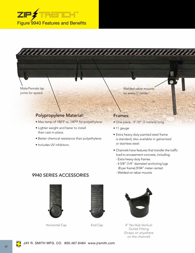
trenchip Figure 9940 Features and Benefits
9940 SERIES ACCESSORIES
4” No-Hub VerticalOutlet Fitting
(Snaps on anywhereon the channel)
Horizontal Cap End Cap
JAY R. SMITH MFG. CO. 800.467.6484 www.jrsmith.comJAY R. SMITH MFG. CO. 800.467.6484 www.jrsmith.com17
Welded rebar mountson every 5’ center
Male/Female lapjoints for speed
Frames:• One piece - 9’-10” (3 meters) long.
• 11 gauge
• Extra heavy-duty painted steel frame is standard; also available in galvanized or stainless steel.
• Channels have features that transfer the traffic load to encasement concrete, including: - Extra heavy-duty frames - 4 5/8” (1/4” diameter) anchoring lugs (8 per frame) (9.84” meter center) - Welded-on rebar mounts
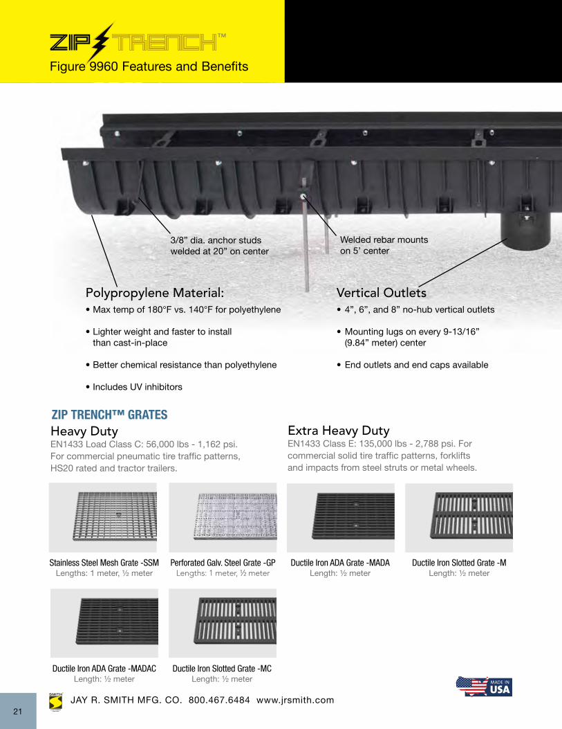
Polypropylene Material:• Max temp of 180°F vs. 140°F for polyethylene
• Lighter weight and faster to install than cast-in-place.
• Better chemical resistance than polyethylene.
• Includes UV inhibitors.

trenchip Figure 9940 Features and Benefits
Weight:• Average weight—channel and frame without grates is 45 lbs.
• Grate weight is listed on the back page.
Grate types:
Class A - Stainless steel perforated and slotted - Galvanized steel perforated and slotted - Black polypropylene slotted and ADAClass B - Stainless steel mesh Class C - Stainless steel perforated, mesh and slotted - Galvanized steel perforated, mesh, slotted and brickslot - Ductile iron mosaic and decorative - Plastic resin slotted Class E - Stainless steel slotted - Galvanized steel slotted - Ductile iron slotted and ADA
Other Views:
JAY R. SMITH MFG. CO. 800.467.6484 www.jrsmith.com37 18
Heavy polypropylene ribbing throughout to reinforce during concrete pour
Anchoring lugs
Outlets• Snap on 4” no-hub vertical outlet can be located virtually anywhere on the channel
• End outlets and end caps available. (see page 17)

12” Wide Trench Drains - Figure 9960
JAY R. SMITH MFG. CO. 800.467.6484 www.jrsmith.com
ZIP TRENCH™ FEATURES:
• Fast, long, pre-assembled runs: 9’-10” (3 meter) long channels• 16 channels—12 sloping and 4 neutral from a depth of 7-9/16 “- 22-9/16” • Built-in slope 1.07%• 4 grate types: Class C - Stainless steel perforated and mesh - Galvanized steel perforated and mesh Class E - Ductile Iron ADA
- Ductile Iron Slotted
ENLARGED END VIEW
SIDE VIEW
TOP VIEW Welded Installation DeviceFor Rebar Support(4 Per Frame)(Rebar Posts By Others)
9 5/8" (245)
12 9/16" (319)
20 3/8" (518)
1 9/16"(40)
7 9/16" (192)22 9/16" (573)
29 9/16" (750)59 1/2" (1500)29 9/16" (750)
9'-10 1/8" (3000)
Female End Male End
3/8 Diameter5 3/4” Long Anchor Studs
trenchip
• 0-60 feet in 6 sections• Lighter weight and faster to install than polymer concrete• Better chemical resistance than polyethylene• Temperature rating of 180 degrees vs 140 degrees F with polyethylene• Load Class E
POLYPROPYLENE DRAIN SYSTEM
APPLICATIONS Industrial Plants • Warehousing • Pedestrian Walkways Fire and Police Stations • Hangars • AirportsCommercial and Industrial Driveway EntrancesPetrochemical Processing Plants • Greenhouses
JAY R. SMITH MFG. CO. 800.467.6484 www.jrsmith.com
FRONT & SIDE VIEWS:
19
JAY R. SMITH MFG. CO. 800.467.6484 www.jrsmith.com37
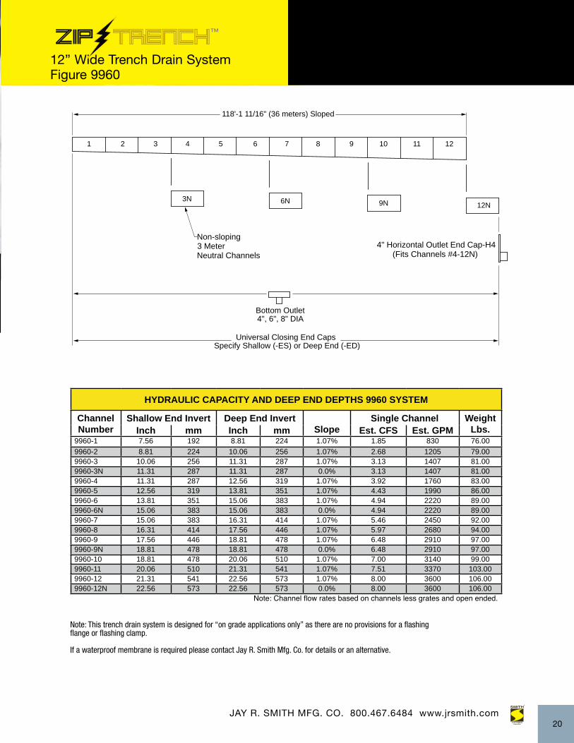
12” Wide Trench Drain System Figure 9960
trenchip
4" Horizontal Outlet End Cap-H4 (Fits Channels #4-12N)
Universal Closing End CapsSpecify Shallow (-ES) or Deep End (-ED)
Non-sloping3 MeterNeutral Channels
ENLARGED END VIEW
1 2 3 4 5 6 7 8 9 10 11 12
3N 6N 9N 12N
SIDE VIEW
TOP VIEW
Bottom Outlet 4", 6", 8" DIA
Welded Installation DeviceFor Rebar Support(4 Per Frame)(Rebar Posts By Others)
9 5/8" (245)
12 9/16" (319)
20 3/8" (518)
1 9/16"(40)
7 9/16" (192)22 9/16" (573)
29 9/16" (750)59 1/2" (1500)29 9/16" (750)
9'-10 1/8" (3000)
Female End Male End
118'-1 11/16" (36 meters) Sloped
HYDRAULIC CAPACITY AND DEEP END DEPTHS 9960 SYSTEM
Channel Number
Shallow End Invert Deep End InvertSlope
Single Channel Weight Lbs.Inch mm Inch mm Est. CFS Est. GPM
9960-1 7.56 192 8.81 224 1.07% 1.85 830 76.009960-2 8.81 224 10.06 256 1.07% 2.68 1205 79.009960-3 10.06 256 11.31 287 1.07% 3.13 1407 81.009960-3N 11.31 287 11.31 287 0.0% 3.13 1407 81.009960-4 11.31 287 12.56 319 1.07% 3.92 1760 83.009960-5 12.56 319 13.81 351 1.07% 4.43 1990 86.009960-6 13.81 351 15.06 383 1.07% 4.94 2220 89.009960-6N 15.06 383 15.06 383 0.0% 4.94 2220 89.009960-7 15.06 383 16.31 414 1.07% 5.46 2450 92.009960-8 16.31 414 17.56 446 1.07% 5.97 2680 94.009960-9 17.56 446 18.81 478 1.07% 6.48 2910 97.009960-9N 18.81 478 18.81 478 0.0% 6.48 2910 97.009960-10 18.81 478 20.06 510 1.07% 7.00 3140 99.009960-11 20.06 510 21.31 541 1.07% 7.51 3370 103.009960-12 21.31 541 22.56 573 1.07% 8.00 3600 106.009960-12N 22.56 573 22.56 573 0.0% 8.00 3600 106.00
Note: Channel flow rates based on channels less grates and open ended.
Note: This trench drain system is designed for “on grade applications only” as there are no provisions for a flashing flange or flashing clamp.
If a waterproof membrane is required please contact Jay R. Smith Mfg. Co. for details or an alternative.
20
JAY R. SMITH MFG. CO. 800.467.6484 www.jrsmith.comJAY R. SMITH MFG. CO. 800.467.6484 www.jrsmith.com
Welded rebar mountson 5’ center
trenchip
Polypropylene Material:• Max temp of 180°F vs. 140°F for polyethylene
• Lighter weight and faster to install than cast-in-place
• Better chemical resistance than polyethylene
• Includes UV inhibitors
Vertical Outlets• 4”, 6”, and 8” no-hub vertical outlets
• Mounting lugs on every 9-13/16” (9.84” meter) center
• End outlets and end caps available
ZIP TRENCH™ GRATES
Stainless Steel Mesh Grate -SSMLengths: 1 meter, ½ meter
Perforated Galv. Steel Grate -GPLengths: 1 meter, ½ meter
Ductile Iron ADA Grate -MADALength: ½ meter
Ductile Iron Slotted Grate -MLength: ½ meter
Heavy DutyEN1433 Load Class C: 56,000 lbs - 1,162 psi.For commercial pneumatic tire traffic patterns,HS20 rated and tractor trailers.
Extra Heavy DutyEN1433 Class E: 135,000 lbs - 2,788 psi. Forcommercial solid tire traffic patterns, forkliftsand impacts from steel struts or metal wheels.
Figure 9960 Features and Benefits
21
3/8” dia. anchor studs welded at 20” on center
Ductile Iron ADA Grate -MADACLength: ½ meter
Ductile Iron Slotted Grate -MCLength: ½ meter

JAY R. SMITH MFG. CO. 800.467.6484 www.jrsmith.com
Heavy polypropylene ribbing throughout to reinforce during concrete pour
Male/female lapjoints for speed
ZIP TRENCH™ ACCESSORIES
4”, 6”, and 8” No-Hub Vertical Outlet Fitting
4”, 6” and 8”UniversalHorizontal Cap
End Cap
trenchip
Frames:• One piece - 9’-10” (3 meters) long. Frame Ships assembled to channel
• 7 gauge
• Extra heavy-duty painted steel frame is standard
• Transfers traffic load to surrounding concrete
• Optional Galvanized or Stainless Steel
Weight:• Average weight—channel and frame without grates is 91 lbs
Figure 9960 Features and Benefits
22
Ribbing every 3” for added sidewall strength and amechanical lock intoencasement concrete
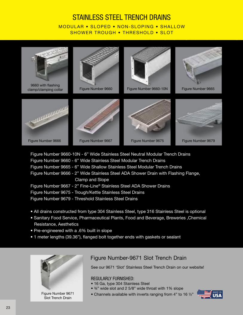
Figure Number 9660-10N - 6” Wide Stainless Steel Neutral Modular Trench Drains
Figure Number 9660 - 6” Wide Stainless Steel Modular Trench Drains
Figure Number 9665 - 6” Wide Shallow Stainless Steel Modular Trench Drains
Figure Number 9666 - 2” Wide Stainless Steel ADA Shower Drain with Flashing Flange,
Clamp and Slope
Figure Number 9667 - 2” Fine-Line® Stainless Steel ADA Shower Drains
Figure Number 9675 - Trough/Kettle Stainless Steel Drains
Figure Number 9679 - Threshold Stainless Steel Drains
• All drains constructed from type 304 Stainless Steel, type 316 Stainless Steel is optional
• Sanitary Food Service, Pharmaceutical Plants, Food and Beverage, Breweries ,Chemical
Resistance, Aesthetics
• Pre-engineered with a .6% built in slope
• 1 meter lengths (39.36”), flanged bolt together ends with gaskets or sealant
19
STAINLESS STEEL TRENCH DRAINSMODULAR • SLOPED • NON-SLOPING • SHALLOW
SHOWER TROUGH • THRESHOLD • SLOT
Figure Number 9660 Figure Number 9660-10N Figure Number 9665
Figure Number 9675 Figure Number 9679Figure Number 9667
9660 with flashingclamp/clamping collar
Figure Number 9666
Figure Number-9671 Slot Trench Drain
See our 9671 ‘Slot’ Stainless Steel Trench Drain on our website!
REGULARLY FURNISHED:• 16 Ga, type 304 Stainless Steel• ¾” wide slot and 2 5/8” wide throat with 1% slope
• Channels available with inverts ranging from 4” to 16 ½”Figure Number 9671Slot Trench Drain
23

STAINLESS STEEL DRAINS 6” Wide Neutral Modular Trench Drains Figure 9660-10N
APPLICATIONS
Commercial Kitchens • Bars • Hotels • RestaurantsPharmaceutical Cleanrooms • Chemical Plants Chemical Storage Areas • Double Containment
FEATURES:
• Stainless steel trench drain is 39.38” long (1m), 6.38”
wide and has a 4” wide throat with bolting end plates
• Complete with dome bottom strainer, leveling studs
and stainless steel 9870-466-SBG bar grate
• Available with 4” center outlet for trough
drain configuration
• Ideal for use in kitchens and other areas where trough drains are required• Excellent for sanitation purposes• “Best In Class” heavy duty type 304 stainless steel construction• Corrosion and vandal-resistant• Modular trench drain body sections• Load Class A - E
39.38 (1000) 1 meter
6.38 (162)4.90 (125)4.00 (102)
19.68 (500)
7.69 (195)INVERT DEPTH
6.25 (159)
SIDE VIEW OF CHANNEL
2 1/2 (64) Typical Dimension from invert of channel to bottom of outlet connection
4 (100) No Hub OutletAnchoring Tabswith Leveling Bolts
SMITH 9660-10N CL
END VIEW OF CHANNEL
39.38 (1000) 1 meter
6.38 (162)4.90 (125)4.00 (102)
19.68 (500)
7.69 (195)INVERT DEPTH
6.25 (159)
SIDE VIEW OF CHANNEL
2 1/2 (64) Typical Dimension from invert of channel to bottom of outlet connection
4 (100) No Hub OutletAnchoring Tabswith Leveling Bolts
SMITH 9660-10N CL
END VIEW OF CHANNEL
OPTIONS:
• Grating Load Classes A-E
• 316 Stainless Steel
• Flashing Flange and Collar
JAY R. SMITH MFG. CO. 800.467.6484 www.jrsmith.com24

JAY R. SMITH MFG. CO. 800.467.6484 www.jrsmith.com
STAINLESS STEEL DRAINS 6” Wide Modular Trench Drains Figure 9660
APPLICATIONS
Food Processing • Bottling Plants • HospitalsCommercial Kitchens • Pharmaceutical cleanrooms Chemical Plants • Chemical Storage Areas Double Containment
FEATURES
• Stainless steel trench drain channels are 39.38”
long (1m), 6.38” wide, and have a 4” wide throat
with bolting end plates
• Ideal for facilities where hygiene, corrosion
resistance, and visibility are imperative
• Available with inverts ranging from 3.75” to 7.50”
• There are 15, 1-meter long sloping, 4, 1-meter
non-sloping and 2, 1/2-meter non-sloping channels
and catch basins available
• Supplied with secured stainless steel 9870-450-SS
slotted grate
• “Best In Class” heavy duty type 304 stainless steel construction• Corrosion and vandal-resistant• Pre-sloped modular trench drain body sections• Option: 316 Stainless Steel• Load Class A - E
39.38 (1000) 1 meter
6.38 (162)4.90 (125)4.00 (102)
3 3/16 (81)2"(51)Top of Flange
2"(51)
“A”INVERT DEPTH PERCHANNEL SECTION
FLOW
SIDE VIEW OF CHANNEL
2 1/2 (64) Typical Dimension from invert of channel to bottom of outlet connection
4 (100) No Hub OutletChannels 2, 5, 10, 15
Flashing Flange and Collar (When Specified)
Anchoring Tabswith Leveling Bolts
When specified -FCWeep Holes supplied
CL
END VIEW OF CHANNEL
NOTE: Dimensions shown inparentheses are in millimeters.
Channel 1 thru 6Channel 7 thru 11Channel 12 thru 15
“A”“A”“A”
6.44 (164)7.69 (195)8.94 (227)
OPTIONS:
• Grating Load Classes A-E
• 316 Stainless Steel
• Flashing Flange
and Collar
25

JAY R. SMITH MFG. CO. 800.467.6484 www.jrsmith.com
6” Wide Modular Stainless Steel Trench Drains - Figure 9660
49' - 2 1/2" (15 meters) Sloped
39.38 (1000) 1 meter6.38 (162)4.90 (125)4.00 (102)
3 3/16 (81)2"(51)Top of Flange
2"(51)
“A”INVERT DEPTH PERCHANNEL SECTION
FLOW
SIDE VIEW OF CHANNEL
1
4 (1 meter) Sloped Channels with 4" Vertical Outlet
2 1/2 (64) Typical Dimension from invert of channel to bottom of outlet connection
4 (1 meter) Non-SlopingNeutral Channels
4 (100) No Hub OutletChannels 2, 5, 10, 15
Flashing Flange and Collar (When Specified)
Anchoring Tabswith Leveling Bolts
*Available with 4" Center Outlet for Trough Drain Configuration
2 3 4 5
5Y
6 7 8 9 10
10Y
11 12 13 14 15
15Y
**9660 -CB Connects to Ch. #15 only
9660
-CB
**
4" No HubSide Outlet
26.43(671)
1' - 7 11/16"(671)
2Y
5N
045N 095N
When specified -FCWeep Holes supplied
10N 15N2N
*10NY
CL
END VIEW OF CHANNEL
NOTE: Dimensions shown inparentheses are in millimeters.
Channel 1 thru 6Channel 7 thru 11Channel 12 thru 15
“A”“A”“A”
6.44 (164)7.69 (195)8.94 (227)
1/2 MeterNeutralChannel
1/2 MeterNeutralChannel
STAINLESS STEEL TRENCH DRAIN - AVAILABLE SECTIONS
Channel NumberShallow Invert Depth
Deep Invert Depth
“A” Body Height
Deep End
Bottom Outlet Size
Avail.End Outlet Size Avail.
Max Flow Rate*
GPM CFS9660-1 3.75 (95) 4.00 (102) 6.44 (164) – 102 .239660-2 4.00 (102) 4.25 (108) 6.44 (164) – 2” 115 .269660-2 Outlet -Y 4.00 (102) 4.25 (108) 6.44 (164) 4” 115 .269660-2 Neutral 4.25 (108) 4.25 (108) 6.44 (164) – 2” 115 .269660-3 4.25 (108) 4.50 (114) 6.44 (164) – 128 .299660-4 4.50 (114) 4.75 (121) 6.44 (164) – 141 .319660-045 1/2 Neutral 4.50 (114) 4.75 (121) 6.44 (164) – 141 .319660-5 4.75 (121) 5.00 (127) 6.44 (164) – 2”, 3” 154 .349660-5 Outlet -Y 4.75 (121) 5.00 (127) 6.44 (164) 4” 154 .349660-5 Neutral 5.00 (127) 5.00 (127) 6.44 (164) – 2”, 3” 154 .349660-6 5.00 (127) 5.25 (133) 6.44 (164) – 2”, 3” 167 .379660-7 5.25 (133) 5.50 (140) 7.69 (195) – 183 .419660-8 5.50 (140) 5.75 (146) 7.69 (195) – 196 .449660-9 5.75 (146) 6.00 (152) 7.69 (195) – 209 .479660-095 1/2 Neutral 5.75 (146) 6.00 (152” 7.69 (195) – 209 .479660-10 6.00 (152) 6.25 (159) 7.69 (195) – 2”, 3”, 4” 222 .509660-10 Outlet -Y 6.00 (152) 6.25 (159) 7.69 (195) 4” 222 .509660-10 Neutral 6.25 (159) 6.25 (159) 7.69 (195) – 2”, 3”, 4” 222 .509660-10 N-Outlet -Y 6.25 (159) 6.25 (159) 7.69 (195) 4” 222 .509660-11 6.25 (159) 6.50 (165) 7.69 (195) – 235 .529660-12 6.50 (165) 6.75 (171) 8.94 (227) – 248 .559660-13 6.75 (171) 7.00 (178) 8.94 (227) – 261 .589660-14 7.00 (178) 7.25 (184) 8.94 (227) – 274 .619660-15 7.25 (184) 7.50 (190) 8.94 (227) – 2”, 3”, 4” 287 .649660-15 Outlet -Y 7.25 (184) 7.50 (190) 8.94 (227) 4” 287 .649660-15 Neutral 7.50 (190) 7.50 (190) 8.94 (227) – 2”, 3”, 4” 287 .64
*Based on open-ended channel less grate with no outlet cap
26
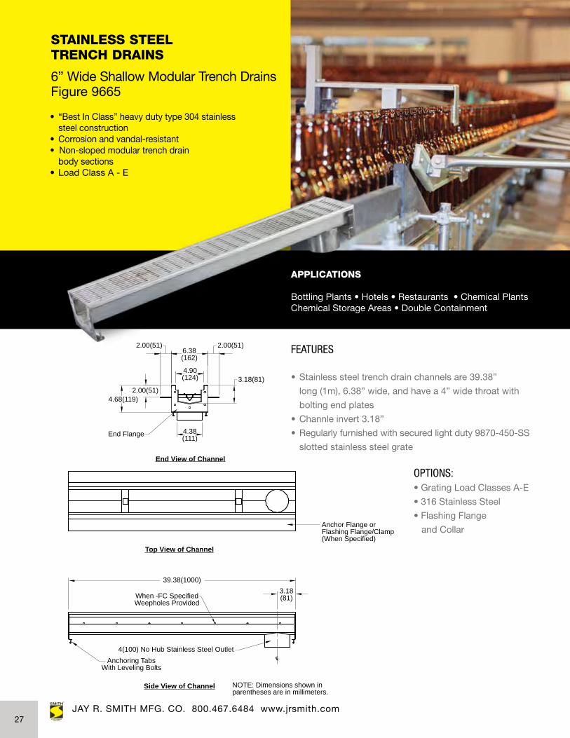
STAINLESS STEEL TRENCH DRAINS 6” Wide Shallow Modular Trench Drains Figure 9665
APPLICATIONS
Bottling Plants • Hotels • Restaurants • Chemical Plants Chemical Storage Areas • Double Containment
FEATURES
• Stainless steel trench drain channels are 39.38”
long (1m), 6.38” wide, and have a 4” wide throat with
bolting end plates
• Channle invert 3.18”
• Regularly furnished with secured light duty 9870-450-SS
slotted stainless steel grate
JAY R. SMITH MFG. CO. 800.467.6484 www.jrsmith.com
• “Best In Class” heavy duty type 304 stainless steel construction• Corrosion and vandal-resistant• Non-sloped modular trench drain body sections• Load Class A - E
CL
Anchor Flange orFlashing Flange/Clamp(When Specified)
2.00(51)
39.38(1000)
2.00(51)4.68(119)
2.00(51)
3.18(81)
3.18(81)
6.38(162)
4.90(124)
4.38(111)End Flange
NOTE: Dimensions shown inparentheses are in millimeters.
Side View of Channel
Top View of Channel
End View of Channel
When -FC SpecifiedWeepholes Provided
Anchoring TabsWith Leveling Bolts
4(100) No Hub Stainless Steel Outlet
OPTIONS:• Grating Load Classes A-E
• 316 Stainless Steel
• Flashing Flange
and Collar
27

SECTION A-A
A A
2.38
2.00
1.50
1.00
1.50
5.00
Specify Dimension +3.00 (76)
Specify Dimension1.50
Sloped to Outlet
2.00(51) NO-HUB Vertical Outlet
When Specified Flashing Flange & Flashing Clamp (-FC)
2.00
STAINLESS STEEL SHOWER DRAINS 2” Wide ADA Shower Drains with Flashing Flange, Clamp and Slope Figure 9666
FEATURES:
• Fabricated 14-gauge type 304 stainless steel body
• Vandal-resistant stainless steel perforated grate
• 2” No-Hub bottom outlet
• Standard grate has .25” diameter perforations
• Optional decorative grating available: tile inlay,
slotted, wave and solid rim
See submittal for details
JAY R. SMITH MFG. CO. 800.467.6484 www.jrsmith.com
• Durable stainless drain construction• Vandal-proof • ADA compliant perforated grating• Engineered System
OPTIONS:
• Vandal-resistant
• Ligature-Resistant
• 316 Stainless Steel
APPLICATIONS
Hospitals • Rehabilitation Facilities Behavioral Healthcare • Nursing Homes
28

STAINLESS STEEL SHOWER DRAINS 2” Fine-Line® ADA Shower Drains Figure 9667
FEATURES:
• Stainless steel drain body with satin finish grates
• Customize your drain with designer grate options
for a soothing, artistic, or clean and elegant look
JAY R. SMITH MFG. CO. 800.467.6484 www.jrsmith.com
• Add artful design to your shower stall• Pairs perfectly with natural stone, marble, ceramic tile, porcelain and solid surface• ADA compliant
APPLICATIONS
Residential Designer Showers • Homes • Apartments Condominiums • Luxury Hotels • Country Clubs
2.38
AA .25 SQ Openings
2.00
SECTION A-A
SECTION B-B
B
B
2" NO-HUB Outlet
1.50
2.25 1.501.50
Flashing Flange(When Specified)
.88.50
2.03
5.25
Specify Length + 3.12
Specify LengthUp to 5' Max2.38
AA .25 SQ Openings
2.00
SECTION A-A
SECTION B-B
B
B
2" NO-HUB Outlet
1.50
2.25 1.501.50
Flashing Flange(When Specified)
.88.50
2.03
5.25
Specify Length + 3.12
Specify LengthUp to 5' Max
29

JAY R. SMITH MFG. CO. 800.467.6484 www.jrsmith.com
2” Fine-Line® Stainless Steel ADA Shower Drains - Figure 9667
Fine-Line® Grates
OPTIONS
• Type 316 stainless steel
• Vandal-Proof grates
• Custom lengths/Multiple outlets
• Flashing Flange
Tile Inlay Grate -TIG Slotted Grate -SG Solid Rim FlowGrate -SRFG
Wave Grate -WG Regularly Furnished SSPerforated Grate -SPG
OPTIONAL WAVE GRATE -WG
OPTIONAL SOLID RIM FLOW GRATE -SRFG
OPTIONAL TILE INLAY GRATE -TIG
2.00
2.00
2.00
.25 x 1.25 Slots Staggered (TYP.)
OPTIONAL SLOTTED GRATE -SG
2.00
.25 SQ Openings
2.00
Regularly Furnished Steel Perforated Grate -SPG
JAY R. SMITH MFG. CO. 800.467.6484 www.jrsmith.com30

JAY R. SMITH MFG. CO. 800.467.6484 www.jrsmith.comJAY R. SMITH MFG. CO. 800.467.6484 www.jrsmith.com
STAINLESS STEEL DRAINS ‘Trough/Kettle’ Drains Figure 9675
FEATURES:
• Fabricated 14-gauge type 304 stainless steel body
• Sediment bucket
• 4” No-Hub bottom outlet
• Anchor tabs and stainless steel light duty bar grating
• Subway style grate
A (*Pipe Size) = 04 (101)
Anchor Tab
A
3/16 (5) 1/2 13)
2 (51)
3 (76)
When SpecifiedFlashing Clamp -FC
4 (25.4)
Perforated Sediment Bucket
1/8" (3) Per Foot Slope Min.H
Stainless Steel ADA Bar Grating
3 (76)
L
W
1 (25.4) Reveal
1 (25.4) Reveal
1 (25.4) Reveal
1 (25.4) Reveal
2(51)2(51) TYP
APPLICATIONS
Commercial Kitchens • Food Processing Areas
• Ideal for large commercial kitchens• Durable and versatile• Used as kettle drains, floor drains or trough drains• Load Class A and B
AVAILABLE SIZES
W L H
9675-1224 12” (305) 24” (610) 9 1/8” (232)9675-1236 12” (305) 36” (914) 9 3/16” (233)9675-1248 12” (305) 48” (1219) 9 1/4” (235)9675-1260 12” (305) 60” (1524) 9 3/8” (238)9675-1824 18” (305) 24” (1524) 9 1/8” (232)9675-1836 18” (305) 36” (1524) 9 3/16” (233)9675-1848 18” (305) 48” (1524) 9 1/4” (235)9675-1860 18” (305) 60” (1524) 9 3/8” (238)
OPTIONS:• 316 Stainless Steel
• Custom Grating
• Flashing Flange
and Collar
31

JAY R. SMITH MFG. CO. 800.467.6484 www.jrsmith.com
STAINLESS STEEL DRAINS Threshold Drains™ Figure 9679
FEATURES:
• Heel-proof grate prevents injury• Customizable to work with all building structure conditions• Easily removable grating for fast cleaning and maintenance• Complies with nationwide Building/Fire Codes• ADA compliant• 1.75” deep for post tension slabs• Load Class A
Specify L1 (Max 10'-3")
Front View Shown
Top View Shown
End View Shown
1 3/4"Min.
Specify L2 (Min. 12") Specify L3
Specify Length L1 In InchesMinimum Length To Meet 100 GPM Requirement = 3'-6"
4" No Hub Outlet
Anchor Strap
3"
1/2"-13 NPT Trap Primer When Specified:
Connection -P
CL
Cent.
4
Maximum Length To Meet 100 GPM Requirement = 10'-3"
3" 2"
13 9/16"Min.
6 1/2"Dia.
4 3/8" Dia.
APPLICATIONS
For use in front of elevators, doorways, stairwaysand similar applications to receive and drain water with flow rates up to 100 GPM with no bypass.
Specify L1 (Max 10'-3")
Front View Shown
Top View Shown
End View Shown
1 3/4"Min.
Specify L2 (Min. 12") Specify L3
Specify Length L1 In InchesMinimum Length To Meet 100 GPM Requirement = 3'-6"
4" No Hub Outlet
Anchor Strap
3"
1/2"-13 NPT Trap Primer When Specified:
Connection -P
CL
Cent.
4
Maximum Length To Meet 100 GPM Requirement = 10'-3"
3" 2"
13 9/16"Min.
6 1/2"Dia.
4 3/8" Dia.
• Complies with 2013 California Building Code 403.6.1, 403.6.2, 3007.4, 3008.4• Complies with San Francisco Fire Code, Section 511.1.4• IBC Code 3007.3 Water protection. The occupant evacuation elevator hoistway and associated elevator landings shall be designed by an approved method to prevent water from infiltrating into the shaft enclosure• For use in front of elevator doors and similar applications• Third party certified to 100 gpm flow rate with no bypass• ADA compliant• Heel-proof• 1 3/4” deep; does not disturb post-tension slabs• 304 Stainless Steel
• Removable grating
JAY R. SMITH MFG. CO. 800.467.6484 www.jrsmith.com
Specify from 42” to
Max 10’3”
OPTIONS• 316 Stainless Steel
• Tile Inlay Grate
• Color
• Anchor Straps
• Trap Primer Connection
32
Patent #10,167,621

POLYMER CONCRETE TRENCH DRAINS3” TO 14” WIDE - 9800 SERIES
Figure Number 9895 - 6” Wide ‘Pre-Sloped’ Polymer Concrete Trench Drains with
Integral Metal Rail - KlassikDrain®
Figure Number 9877 - 6” Wide ‘Pre-Sloped’ Polymer Concrete Trench Drains with Ductile
Iron Edge Rail for Extra Heavy Applications- PowerDrain®
Figure Number 9832 - 6” Wide ‘Non-Sloped’ ‘Shallow’ Polymer Concrete Trench Drains
Figure Number 9805 - 6” Wide ‘Non-Sloped’ Polymer Concrete Trench Drains with
Ductile Iron Edge Rail for Extra Heavy Applications PowerDrain®
Figure Number 9878 - 10” Wide ‘Pre-Sloped’ Polymer Concrete Trench Drains with
Ductile Iron Edge Rail for Extra Heavy Applications PowerDrain®
Figure Number 9806 - 10” Wide ‘Non-Sloped’ Polymer Concrete Trench Drains with
Ductile Iron Edge Rail for Extra Heavy Applications
Figure Number 9898 - 10” Wide ‘Shallow’ Polymer Concrete Trench Drains with Integral
Metal Rail - SlabDrain®
Figure Number 9896 - 10” Wide ‘Pre-Sloped’ Polymer Concrete Trench Drains with
Integral Metal Rail - KlassikDrain®
Figure Number 9807 - 14” Wide ‘Shallow’ Polymer Concrete Trench Drains with Ductile
Iron Edge Rail for Extra Heavy Applications - PowerDrain®
Figure Number 9899 - 14” Wide ‘Non-Sloped’ Polymer Concrete Trench Drains with
Integral Metal Rail - SlabDrain®
Figure Number 9879 - 14” Wide ‘Pre-Sloped’ Polymer Concrete Trench Drains with
Ductile Iron Edge Rail for Extra Heavy Applications - PowerLok®
Figure Number 9897 - 14” Wide Polymer Concrete Trench Drains with Integral Metal
Rail - KlassikDrain®
Figure Number 9836 - 6” Wide ‘Non-Sloped’ Polymer Concrete Shallow Trench Drains
with Integral Galvanized Edge Rail
Figure Number 9833 - 3” Wide ‘No Grade’ ‘Narrow’ Polymer Concrete Trench Drains
33

POLYMER CONCRETE TRENCH DRAINS3” WIDE • 6” WIDE •10” WIDE • 14” WIDE
SHALLOW DEPTH • NARROW WIDTH • SLOPED • NON SLOPING
Figure Number 9896
Figure Number 9899 Figure Number 9879
Figure Number 9836 Figure Number 9833
Figure Number 9897
• Varying widths and depths to meet all application needs.
• Integral cast-in metal rail edge, ductile iron frame and grate, large variety of grates,
shallow, narrow, brickslot, non-sloped—this category has it all.
Figure Number 9878 Figure Number 9898Figure Number 9806
Figure Number 9895 Figure Number 9877 Figure Number 9832 Figure Number 9805
Figure Number 9807
34
JAY R. SMITH MFG. CO. 800.467.6484 www.jrsmith.com
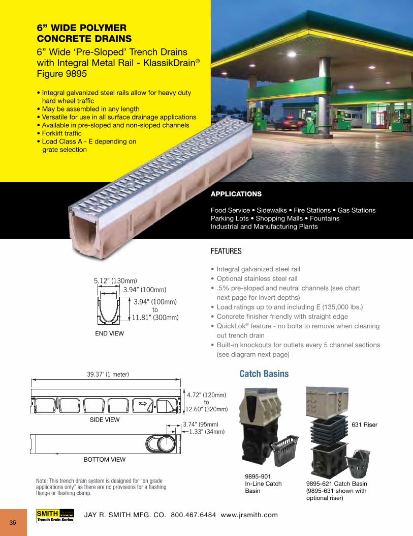
6” WIDE POLYMER CONCRETE DRAINS 6” Wide ‘Pre-Sloped’ Trench Drains with Integral Metal Rail - KlassikDrain®
Figure 9895
APPLICATIONS
Food Service • Sidewalks • Fire Stations • Gas Stations Parking Lots • Shopping Malls • FountainsIndustrial and Manufacturing Plants
• Integral galvanized steel rails allow for heavy duty hard wheel traffic• May be assembled in any length• Versatile for use in all surface drainage applications• Available in pre-sloped and non-sloped channels• Forklift traffic• Load Class A - E depending on grate selection
FEATURES
• Integral galvanized steel rail • Optional stainless steel rail• .5% pre-sloped and neutral channels (see chart next page for invert depths)• Load ratings up to and including E (135,000 lbs.)• Concrete finisher friendly with straight edge• QuickLok® feature - no bolts to remove when cleaning out trench drain• Built-in knockouts for outlets every 5 channel sections (see diagram next page)
Catch Basins
9895-901In-Line Catch Basin
9895-621 Catch Basin(9895-631 shown withoptional riser)
631 Riser
Note: This trench drain system is designed for “on gradeapplications only” as there are no provisions for a flashing flange or flashing clamp.
35

FEATURES
• Integral galvanized steel rail • Optional stainless steel rail• .5% pre-sloped and neutral channels (see chart next page for invert depths)• Load ratings up to and including E (135,000 lbs.)• Concrete finisher friendly with straight edge• QuickLok® feature - no bolts to remove when cleaning out trench drain• Built-in knockouts for outlets every 5 channel sections (see diagram next page)
5 1/8 (130)3.94 (100)
4.75 (120) -12.62 (321)
END VIEW
Catch Basin9895-901-CB
Catch Basin9895-901-CB
Catch Basin9895-901-CB
Catch Basin9895-901-CB
Catch Basin9895-621-CB
Catch Basin9895-621-CB
Catch Basin9895-621-CB
Catch Basin9895-621-CB
Catch Basin9895-631-CB
Catch Basin9895-631-CB
Catch Basin9895-631-CB
Catch Basin9895-631-CB
131'-3 3/16" (40 meters) Sloped
1 2 3 4 5 6 7 8 9 10 11 12 13 14 15 16 17 18 19 20
9895-EC(Universal Closing/4" Inlet/Outlet Cap)
0103
1/2 Meter NeutralChannels
21 22 23 24 25 26 27 28 29 30 31 32 33 34 35 36 37 38 39 40
00 010 020 030 040
0203
0303
0403
1 Meter Neutral Channels
4" and 6" Knockoutsincluded on every5th channel.
9895-V6F(6" Flumed Bottom Outlet)
9895-I6B 9895-H6B 9895-I6C 9895-H6C
OPTIONAL RAIL MATERIALS:Stainless Steel
TRENCH DEPTH 9895 SYSTEM
Channel Number
Shallow End Invert
Deep End Invert Weight
Lbs.Inch mm Inch mm Slope9895-00 3.94 100 3.94 100 0.0% 28.19895-1 3.94 100 4.13 105 0.5% 28.19895-2 4.13 105 4.33 110 0.5% 28.99895-3 4.33 110 4.53 115 0.5% 29.79895-4 4.53 115 4.72 120 0.5% 30.59895-5 4.72 120 4.92 125 0.5% 31.39895-6 4.92 125 5.12 130 0.5% 32.19895-7 5.12 130 5.31 135 0.5% 32.99895-8 5.31 135 5.51 140 0.5% 33.79895-9 5.51 140 5.71 145 0.5% 34.59895-10 5.71 145 5.91 150 0.5% 35.39895-010 5.91 150 5.91 150 0.0% 35.39895-103 5.91 150 5.91 1150 0.0% 17.09895-11 5.91 150 6.10 155 0.5% 36.19895-12 6.10 155 6.30 160 0.5% 36.99895-13 6.30 160 6.50 165 0.5% 37.79895-14 6.50 165 6.69 170 0.5% 38.59895-15 6.69 170 6.89 175 0.5% 39.39895-16 6.89 175 7.09 180 0.5% 40.19895-17 7.09 180 7.28 185 0.5% 40.99895-18 7.28 185 7.48 190 0.5% 41.79895-19 7.48 190 7.68 195 0.5% 42.59895-20 7.68 195 7.88 200 0.5% 43.49895-020 7.88 200 7.88 200 0.0% 43.49895-203 7.88 200 7.88 200 0.0% 20.5
TRENCH DEPTH 9895 SYSTEM
Channel Number
Shallow End Invert
Deep End Invert Weight
Lbs.Inch mm Inch mm Slope9895-21 7.88 200 8.07 205 0.5% 44.29895-22 8.07 205 8.27 210 0.5% 45.09895-23 8.27 210 8.46 215 0.5% 45.89895-24 8.46 215 8.66 220 0.5% 46.89895-25 8.66 220 8.86 225 0.5% 47.49895-26 8.86 225 9.06 230 0.5% 48.29895-27 9.06 230 9.25 235 0.5% 49.09895-28 9.25 235 9.45 240 0.5% 49.89895-29 9.45 240 9.65 245 0.5% 50.69895-30 9.65 245 9.84 250 0.5% 51.49895-030 9.84 250 9.84 250 0.0% 51.49895-303 9.84 250 9.84 250 0.0% 24.09895-31 9.84 250 10.04 266 0.5% 52.29895-32 10.04 255 10.24 260 0.5% 53.09895-33 10.24 260 10.43 265 0.5% 53.89895-34 10.43 265 10.63 270 0.5% 54.69895-35 10.63 270 10.83 275 0.5% 55.49895-36 10.83 275 11.02 280 0.5% 56.29895-37 11.02 280 11.22 285 0.5% 57.09895-38 11.22 285 11.42 290 0.5% 57.99895-39 11.42 290 11.61 295 0.5% 58.79895-40 11.61 295 11.81 300 0.5% 59.59895-040 11.81 300 11.81 300 0.0% 59.59895-403 11.81 300 11.81 300 0.0% 27.5
Note: For overall depth of channel add .80” to invert depth shown.
6” Wide ‘Pre-Sloped’ Polymer Concrete Trench Drains with Integral Metal Rail KlassikDrain® - Figure 9895
JAY R. SMITH MFG. CO. 800.467.6484 www.jrsmith.com36

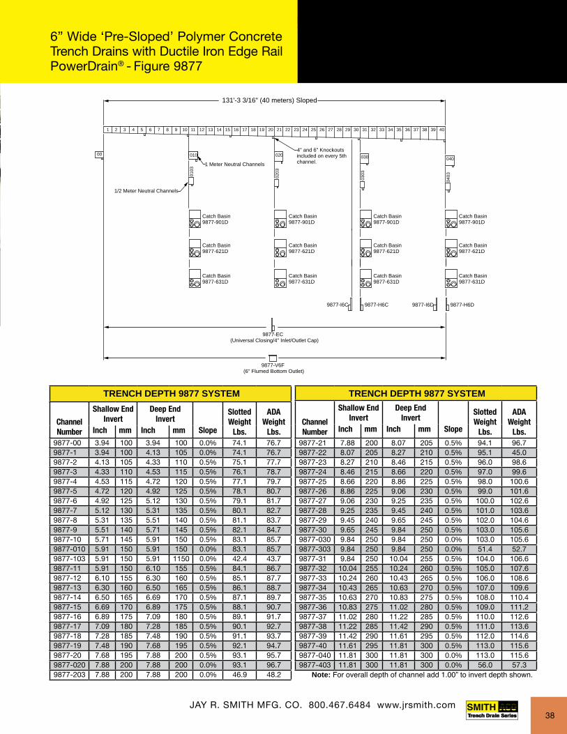
6” WIDE POLYMER CONCRETE DRAINS 6” Wide ‘Pre-Sloped’ Trench Drains with Ductile Iron Edge Rail for Extra Heavy Applications - PowerDrain®
Figure 9877
• Extra heavy duty integral ductile iron rails allow for heavy duty hard wheel traffic• May be assembled in any length• Versatile for use in all surface drainage applications• Convenient interlocking design• Load Class F
APPLICATIONS
Warehousing • Bottling Plants • Industrial PlantsLoading Docks • Fire Stations • Military BasesHighways • Airports • Hangars • Frequent Traffic Areas
Catch Basins
9877-902DIn-Line Catch Basin 9877-621D Catch Basin
(9877-631D shown withoptional riser)
631 Riser
FEATURES
• The 9877 is the extra heavy duty version of the 9895• .5% pre-sloped channels and non-sloping channels• Includes ductile iron frame and grate• Grating options include ADA and bicycle safe• Frame and grate designed to prevent longitudinal and lateral movement• End frames terminate the ends of each run for superior structural integrity
39.37” (1 meter)
4.92” (125 mm)to
12.80” (325 mm)
5.98” (152 mm)
3.94” (100 mm)
3.94” (100 mm)to
11.81” (300 mm)
3.74” (95 mm)
1.33 (34 mm)
39.37” (1 meter)
4.92” (125 mm)to
12.80” (325 mm)
5.98” (152 mm)
3.94” (100 mm)
3.94” (100 mm)to
11.81” (300 mm)
3.74” (95 mm)
1.33 (34 mm)
JAY R. SMITH MFG. CO. 800.467.6484 www.jrsmith.com
Note: This trench drain system is designed for “on grade applications only” as there are no provisions for a flashing flange or flashing clamp.
Regularly furnished with boltless PowerLok® securing device.
37
FEATURES
• The 9877 is the extra heavy duty version of the 9895• .5% pre-sloped channels and non-sloping channels• Includes ductile iron frame and grate• Grating options include ADA and bicycle safe• Frame and grate designed to prevent longitudinal and lateral movement• End frames terminate the ends of each run for superior structural integrity
Catch Basin9877-901D
Catch Basin9877-901D
Catch Basin9877-901D
Catch Basin9877-901D
Catch Basin9877-621D
Catch Basin9877-621D
Catch Basin9877-621D
Catch Basin9877-621D
Catch Basin9877-631D
Catch Basin9877-631D
Catch Basin9877-631D
Catch Basin9877-631D
131'-3 3/16" (40 meters) Sloped
1 2 3 4 5 6 7 8 9 10 11 12 13 14 15 16 17 18 19 20
9877-EC(Universal Closing/4" Inlet/Outlet Cap)
0103
1/2 Meter Neutral Channels
21 22 23 24 25 26 27 28 29 30 31 32 33 34 35 36 37 38 39 40
00 010 020 030 040
0203
0303
0403
1 Meter Neutral Channels
4" and 6" Knockoutsincluded on every 5thchannel.
9877-V6F(6" Flumed Bottom Outlet)
9877-I6C 9877-H6C 9877-I6D 9877-H6D
6 (152)
4 (100)
4 13/16 (125) - 11 13/16 (325)
END VIEW
TRENCH DEPTH 9877 SYSTEM
Channel Number
Shallow End Invert
Deep End Invert
Slotted Weight
Lbs.
ADA Weight
Lbs.Inch mm Inch mm Slope9877-00 3.94 100 3.94 100 0.0% 74.1 76.79877-1 3.94 100 4.13 105 0.0% 74.1 76.79877-2 4.13 105 4.33 110 0.5% 75.1 77.79877-3 4.33 110 4.53 115 0.5% 76.1 78.79877-4 4.53 115 4.72 120 0.5% 77.1 79.79877-5 4.72 120 4.92 125 0.5% 78.1 80.79877-6 4.92 125 5.12 130 0.5% 79.1 81.79877-7 5.12 130 5.31 135 0.5% 80.1 82.79877-8 5.31 135 5.51 140 0.5% 81.1 83.79877-9 5.51 140 5.71 145 0.5% 82.1 84.79877-10 5.71 145 5.91 150 0.5% 83.1 85.79877-010 5.91 150 5.91 150 0.0% 83.1 85.79877-103 5.91 150 5.91 1150 0.0% 42.4 43.79877-11 5.91 150 6.10 155 0.5% 84.1 86.79877-12 6.10 155 6.30 160 0.5% 85.1 87.79877-13 6.30 160 6.50 165 0.5% 86.1 88.79877-14 6.50 165 6.69 170 0.5% 87.1 89.79877-15 6.69 170 6.89 175 0.5% 88.1 90.79877-16 6.89 175 7.09 180 0.5% 89.1 91.79877-17 7.09 180 7.28 185 0.5% 90.1 92.79877-18 7.28 185 7.48 190 0.5% 91.1 93.79877-19 7.48 190 7.68 195 0.5% 92.1 94.79877-20 7.68 195 7.88 200 0.5% 93.1 95.79877-020 7.88 200 7.88 200 0.0% 93.1 96.79877-203 7.88 200 7.88 200 0.0% 46.9 48.2
TRENCH DEPTH 9877 SYSTEM
Channel Number
Shallow End Invert
Deep End Invert
Slotted Weight
Lbs.
ADA Weight
Lbs.Inch mm Inch mm Slope
9877-21 7.88 200 8.07 205 0.5% 94.1 96.79877-22 8.07 205 8.27 210 0.5% 95.1 45.09877-23 8.27 210 8.46 215 0.5% 96.0 98.69877-24 8.46 215 8.66 220 0.5% 97.0 99.69877-25 8.66 220 8.86 225 0.5% 98.0 100.69877-26 8.86 225 9.06 230 0.5% 99.0 101.69877-27 9.06 230 9.25 235 0.5% 100.0 102.69877-28 9.25 235 9.45 240 0.5% 101.0 103.69877-29 9.45 240 9.65 245 0.5% 102.0 104.69877-30 9.65 245 9.84 250 0.5% 103.0 105.69877-030 9.84 250 9.84 250 0.0% 103.0 105.69877-303 9.84 250 9.84 250 0.0% 51.4 52.79877-31 9.84 250 10.04 255 0.5% 104.0 106.69877-32 10.04 255 10.24 260 0.5% 105.0 107.69877-33 10.24 260 10.43 265 0.5% 106.0 108.69877-34 10.43 265 10.63 270 0.5% 107.0 109.69877-35 10.63 270 10.83 275 0.5% 108.0 110.49877-36 10.83 275 11.02 280 0.5% 109.0 111.29877-37 11.02 280 11.22 285 0.5% 110.0 112.69877-38 11.22 285 11.42 290 0.5% 111.0 113.69877-39 11.42 290 11.61 295 0.5% 112.0 114.69877-40 11.61 295 11.81 300 0.5% 113.0 115.69877-040 11.81 300 11.81 300 0.0% 113.0 115.69877-403 11.81 300 11.81 300 0.0% 56.0 57.3
Note: For overall depth of channel add 1.00” to invert depth shown.
6” Wide ‘Pre-Sloped’ Polymer Concrete Trench Drains with Ductile Iron Edge Rail PowerDrain® - Figure 9877
JAY R. SMITH MFG. CO. 800.467.6484 www.jrsmith.com JAY R. SMITH MFG. CO. 800.467.6484 www.jrsmith.com38

39.37" (1 meter)
3.54" (90 mm)1.37" (35 mm) 6.1" (155 mm)
4.0" (100 mm)
1.0" (25 mm)6.1" (155 mm)
3.15" (80 mm) or4.0" (100 mm)
3.15" (80 mm)or 4.0" (100 mm)
4” sch. 40 drill-out
SIDE VIEW
BOTTOM VIEW
END VIEW
QuickLok® is a registered trademark of ACO Polymer Products, Inc.
6” SHALLOW DEPTH POLYMER CONCRETE DRAINS 6” Wide ‘Non-Sloped’ Shallow Trench Drains - Figure 9832
APPLICATIONS
Shopping Malls • Pedestrian Areas Commercial Areas
39.37" (1 meter)
3.54" (90 mm)1.37" (35 mm) 6.1" (155 mm)
4.0" (100 mm)
1.0" (25 mm)6.1" (155 mm)
3.15" (80 mm) or4.0" (100 mm)
3.15" (80 mm)or 4.0" (100 mm)
4” sch. 40 drill-out
• Reduce installation time and cost with interlocking tongue and groove ends• Ideal for restricted installation depths• May be assembled in any length• Load Rated from A - C
FEATURES:• 1 meter (3.28’) precast polyester polymer
concrete construction
• High-strength, lightweight channels feature
interlocking design
• Groove profile for ease of installation and alignment
• Non-sloping bottom
• Supplied with secured grate per specification
• Designed for on-grade applications only; no provisions
for flashing flange or clamp
JAY R. SMITH MFG. CO. 800.467.6484 www.jrsmith.com39
Note: This trench drain system is designed for “on grade applications only” as there are no provisions for a flashing flange or flashing clamp.

6” WIDE POLYMER CONCRETE DRAINS 6” Wide ‘Non-Sloped’ Trench Drains with Ductile Iron Edge Rail for Extra Heavy Applications - PowerDrains®
Figure 9805
APPLICATIONS
Docks & Ports • Taxiways • Gate Areas • HangarsHeavy Fork Trucks • Heavy Wheel LoadsFrequent Traffic Areas
FEATURES:
• 1 meter (3.28’) precast polyester concrete
channel construction
• Interlocking design with no slope
• Integral ductile iron edge rail
• 4” internal width, supplied with secured ductile iron
slotted or ADA grates *See note
• Designed for on-grade applications only; no provisions
for flashing flange or clamp
4" (102)
39 3/8" (1000)
6 1/4" (159)
3 9/16" (91)
6 1/8"(155)
4" (102)
SIDE VIEW
BOTTOM VIEW
END VIEW
4" (102) Sch 40 Drillout
4" (102)
39 3/8" (1000)
6 1/4" (159)
3 9/16" (91)
6 1/8"(155)
4" (102)
SIDE VIEW
BOTTOM VIEW
END VIEW
4" (102) Sch 40 Drillout
• Heavy duty integral ductile iron rails• Versatile use in all surface drainage applications• Shallow, non-sloping channels allow for heavy hard wheel traffic• Load Rated F
JAY R. SMITH MFG. CO. 800.467.6484 www.jrsmith.comRegularly furnished with boltless Power-Lok® securing device.
40
Note: This trench drain system is designed for “on grade applications only” as there are no provisions for a flashing flange or flashing clamp.
*Note: Contact local Jay R. Smith Mfg. Co. manufactur-er’s rep or Jay R. Smith Mfg. Co. Trench Drain Team for grate options
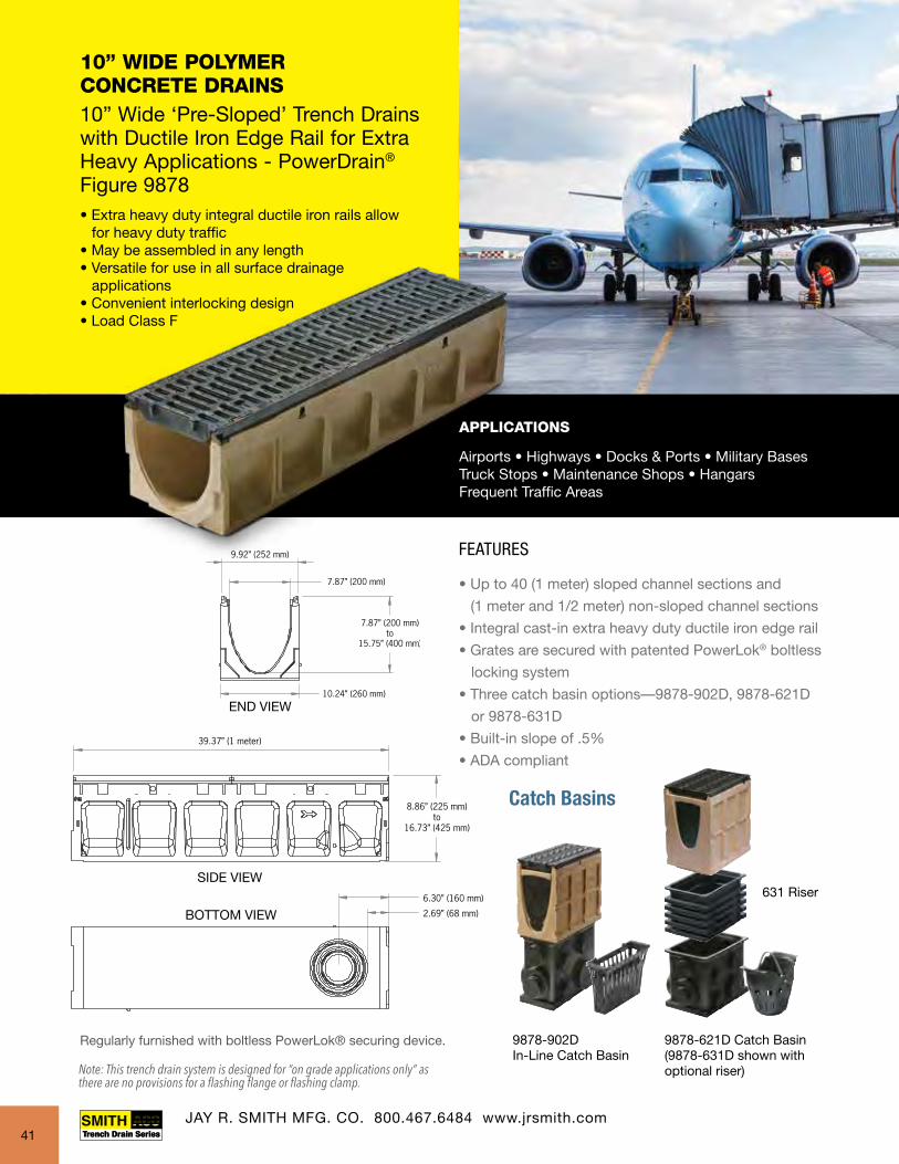
10” WIDE POLYMER CONCRETE DRAINS 10” Wide ‘Pre-Sloped’ Trench Drains with Ductile Iron Edge Rail for Extra Heavy Applications - PowerDrain®
Figure 9878
APPLICATIONS
Airports • Highways • Docks & Ports • Military Bases Truck Stops • Maintenance Shops • HangarsFrequent Traffic Areas
FEATURES
• Up to 40 (1 meter) sloped channel sections and
(1 meter and 1/2 meter) non-sloped channel sections
• Integral cast-in extra heavy duty ductile iron edge rail
• Grates are secured with patented PowerLok® boltless
locking system
• Three catch basin options—9878-902D, 9878-621D
or 9878-631D
• Built-in slope of .5%
• ADA compliant
• Extra heavy duty integral ductile iron rails allow for heavy duty traffic• May be assembled in any length• Versatile for use in all surface drainage applications• Convenient interlocking design• Load Class F
Catch Basins
9878-902DIn-Line Catch Basin
9878-621D Catch Basin(9878-631D shown withoptional riser)
631 Riser
JAY R. SMITH MFG. CO. 800.467.6484 www.jrsmith.com
Regularly furnished with boltless PowerLok® securing device.
41
Note: This trench drain system is designed for “on grade applications only” as there are no provisions for a flashing flange or flashing clamp.

FEATURES
• Up to 40 (1 meter) sloped channel sections and
(1 meter and 1/2 meter) non-sloped channel sections
• Integral cast-in extra heavy duty ductile iron edge rail
• Grates are secured with patented PowerLok® boltless
locking system
• Three catch basin options—9878-902D, 9878-621D
or 9878-631D
• Built-in slope of .5%
• ADA compliant
Catch Basin9878-902D
Catch Basin9878-902D
Catch Basin9878-902D
Catch Basin9878-902D
Catch Basin9878-621D
Catch Basin9878-621D
Catch Basin9878-621D
Catch Basin9878-621D
Catch Basin9878-631D
Catch Basin9878-631D
Catch Basin9878-631D
Catch Basin9878-631D
131'-3 3/16" (40 meters) Sloped
1 2 3 4 5 6 7 8 9 10 11 12 13 14 15 16 17 18 19 20
9878-EC(Universal Closing/Inlet/Outlet Cap)
0103
1/2 Meter Neutral Channels
21 22 23 24 25 26 27 28 29 30 31 32 33 34 35 36 37 38 39 40
00 010 020 030 040
0203
0303
0403
1 Meter Neutral Channels
4" and 6" Knockoutsincluded on every 5thchannel.
10 1/4 (260)
7 7/8 (200)
8 7/8 (225) -16 3/4 (425)
END VIEW
TRENCH DEPTH 9878 SYSTEM
Channel Number
Shallow End Invert
Deep End Invert
Slotted Weight
Lbs.
ADA Weight
Lbs.Inch mm Inch mm Slope9878-00 7.87 200 7.87 200 0.0% 141.2 133.79878-1 7.87 200 8.07 205 0.5% 141.2 133.79878-2 8.07 205 8.27 210 0.5% 142.3 134.89878-3 8.27 210 8.46 215 0.5% 143.4 135.99878-4 8.46 215 8.66 220 0.5% 144.5 137.09878-5 8.66 220 8.86 225 0.5% 145.6 138.19878-6 8.86 225 9.06 230 0.5% 146.7 139.29878-7 9.06 230 9.25 235 0.5% 147.8 140.39878-8 9.25 235 9.45 240 0.5% 148.9 141.49878-9 9.45 240 9.65 245 0.5% 150.0 142.59878-10 9.65 245 9.84 250 0.5% 151.1 143.69878-010 9.84 250 9.84 250 0.0% 151.2 143.79878-103 9.84 250 9.84 250 0.0% 89.2 85.459878-11 9.84 250 10.04 255 0.5% 152.2 144.79878-12 10.04 255 10.24 260 0.5% 153.3 145.89878-13 10.24 260 10.43 265 0.5% 154.4 146.99878-14 10.43 265 10.63 270 0.5% 155.6 148.19878-16 10.63 270 10.83 275 0.5% 156.7 149.29878-16 10.83 275 11.02 280 0.5% 157.8 150.39878-17 11.02 280 11.22 285 0.5% 158.9 151.49878-18 11.22 285 11.42 290 0.5% 160.0 152.59878-19 11.42 290 11.61 295 0.5% 161.1 153.69878-20 11.61 295 11.81 300 0.5% 162.2 154.79878-020 11.81 300 11.81 300 0.0% 162.2 154.79878-203 11.81 300 11.81 300 0.0% 96.8 93.059878-21 11.81 300 12.01 305 0.5% 163.3 155.8
TRENCH DEPTH 9878 SYSTEM
Channel Number
Shallow End Invert
Deep End Invert
Slotted Weight
Lbs.
ADA Weight
Lbs.Inch mm Inch mm Slope
9878-22 12.01 305 12.20 310 0.5% 164.4 156.99878-23 12.20 310 12.40 315 0.5% 165.5 158.09878-24 12.40 315 12.60 320 0.5% 166.6 159.19878-25 12.60 320 12.80 325 0.5% 167.7 160.29878-26 12.80 325 12.99 330 0.5% 168.8 161.39878-27 12.99 330 13.19 335 0.5% 169.9 162.49878-28 13.19 335 13.39 340 0.5% 171.0 163.59878-29 13.39 340 13.58 345 0.5% 172.1 164.69878-30 13.58 345 13.78 350 0.5% 173.2 165.79878-030 13.78 350 13.78 350 0.0% 173.2 165.79878-303 13.78 350 13.78 350 0.0% 101.3 97.559878-31 13.78 350 13.98 355 0.5% 174.4 166.99878-32 13.98 355 14.17 360 0.5% 175.5 168.09878-33 14.17 360 14.37 365 0.5% 176.6 169.19878-34 14.37 365 14.57 370 0.5% 177.7 170.29878-35 14.57 370 14.76 375 0.5% 178.8 171.39878-36 14.76 375 14.96 380 0.5% 179.9 172.49878-37 14.96 380 15.16 385 0.5% 181.0 173.59878-38 15.16 385 15.35 390 0.5% 182.1 174.69878-39 15.35 390 15.55 395 0.5% 183.2 175.79878-40 15.55 395 15.75 400 0.5% 184.3 176.89878-040 15.75 400 15.75 400 0.0% 184.3 176.89878-403 15.75 400 15.75 400 0.0% 110.1 106.4
Note: For overall depth of channel add 1.00” to invert depth shown.
10” Wide ‘Pre-Sloped’ Polymer Concrete Trench Drains with Ductile Iron Edge Rail - PowerDrain® - Figure 9878
JAY R. SMITH MFG. CO. 800.467.6484 www.jrsmith.com42
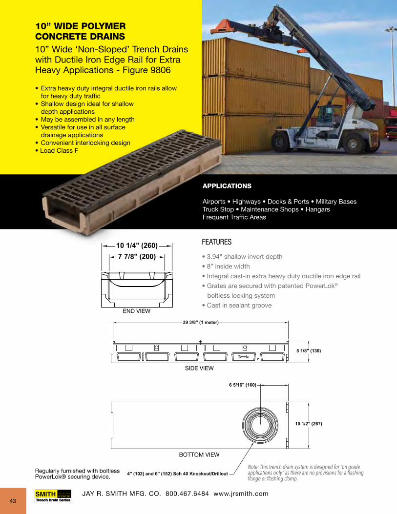
10” WIDE POLYMER CONCRETE DRAINS 10” Wide ‘Non-Sloped’ Trench Drains with Ductile Iron Edge Rail for Extra Heavy Applications - Figure 9806
• Extra heavy duty integral ductile iron rails allow for heavy duty traffic• Shallow design ideal for shallow depth applications• May be assembled in any length• Versatile for use in all surface drainage applications• Convenient interlocking design• Load Class F
APPLICATIONS
Airports • Highways • Docks & Ports • Military Bases Truck Stop • Maintenance Shops • HangarsFrequent Traffic Areas
FEATURES
• 3.94” shallow invert depth
• 8” inside width
• Integral cast-in extra heavy duty ductile iron edge rail
• Grates are secured with patented PowerLok®
boltless locking system
• Cast in sealant groove
JAY R. SMITH MFG. CO. 800.467.6484 www.jrsmith.com
Regularly furnished with boltless PowerLok® securing device.
43
Note: This trench drain system is designed for “on grade applications only” as there are no provisions for a flashing flange or flashing clamp.

10” WIDE POLYMER CONCRETE DRAINS Figure 9898 - 10” Wide ‘Shallow’ Trench Drains with Integral Metal Rail - SlabDrain®
• Integral galvanized steel rails allow for heavy duty hard wheel traffic• Shallow non-sloping channels may be assembled in any length• Versatile for use in all surface drainage applications• Convenient interlocking design• Load Class A - E
FEATURES
• 3.94” invert depth for applications in shallow areas
• 8” inside width
• 4” and 6” bottom knockouts on each channel section
• Grates are secured with patented QuickLok® boltless
locking system
• Galvanized edge rail regularly furnished; stainless
steel rail option available
APPLICATIONS
Decks • Slabs • Retrofit Projects Threshold Applications
JAY R. SMITH MFG. CO. 800.467.6484 www.jrsmith.com JAY R. SMITH MFG. CO. 800.467.6484 www.jrsmith.com44
Note: This trench drain system is designed for “on grade applications only” as there are no provisions for a flashing flange or flashing clamp.
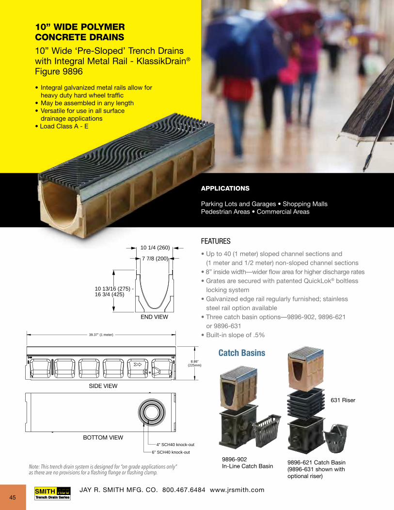
10” WIDE POLYMER CONCRETE DRAINS 10” Wide ‘Pre-Sloped’ Trench Drains with Integral Metal Rail - KlassikDrain® Figure 9896
• Integral galvanized metal rails allow for heavy duty hard wheel traffic• May be assembled in any length• Versatile for use in all surface drainage applications• Load Class A - E
APPLICATIONS
Parking Lots and Garages • Shopping Malls Pedestrian Areas • Commercial Areas
FEATURES
• Up to 40 (1 meter) sloped channel sections and (1 meter and 1/2 meter) non-sloped channel sections• 8” inside width—wider flow area for higher discharge rates• Grates are secured with patented QuickLok® boltless locking system• Galvanized edge rail regularly furnished; stainless steel rail option available• Three catch basin options—9896-902, 9896-621 or 9896-631• Built-in slope of .5%
Catch Basin9896-902CB
Catch Basin9896-902CB
Catch Basin9896-902CB
Catch Basin9896-902CB
Catch Basin9896-621
Catch Basin9896-621
Catch Basin9896-621
Catch Basin9896-621
Catch Basin9896-631
Catch Basin9896-631
Catch Basin9896-631
Catch Basin9896-631
131'-3 3/16" (40 meters) Sloped
1 2 3 4 5 6 7 8 9 10 11 12 13 14 15 16 17 18 19 20
9896-EC(Universal Closing/4" Inlet/Outlet Cap)
0103
1/2 Meter Neutral Channels
21 22 23 24 25 26 27 28 29 30 31 32 33 34 35 36 37 38 39 40
00 010 020 030 040
0203
0303
0403
1 Meter Neutral Channels
4" and 6" Knockoutsincluded on every 5thchannel.
10 1/4 (260)
7 7/8 (200)
10 13/16 (275) - 16 3/4 (425)
END VIEW
Catch Basins
9896-902In-Line Catch Basin
9896-621 Catch Basin(9896-631 shown withoptional riser)
631 Riser
39.37" (1 meter)
8.86"(225mm)
6" SCH40 knock-out
4" SCH40 knock-out
JAY R. SMITH MFG. CO. 800.467.6484 www.jrsmith.com45
Note: This trench drain system is designed for “on grade applications only” as there are no provisions for a flashing flange or flashing clamp.
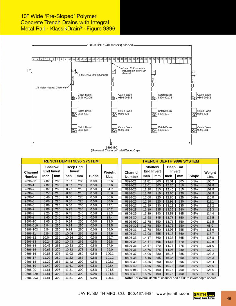
Catch Basin9896-902CB
Catch Basin9896-902CB
Catch Basin9896-902CB
Catch Basin9896-902CB
Catch Basin9896-621
Catch Basin9896-621
Catch Basin9896-621
Catch Basin9896-621
Catch Basin9896-631
Catch Basin9896-631
Catch Basin9896-631
Catch Basin9896-631
131'-3 3/16" (40 meters) Sloped
1 2 3 4 5 6 7 8 9 10 11 12 13 14 15 16 17 18 19 20
9896-EC(Universal Closing/4" Inlet/Outlet Cap)
0103
1/2 Meter Neutral Channels
21 22 23 24 25 26 27 28 29 30 31 32 33 34 35 36 37 38 39 40
00 010 020 030 040
0203
0303
0403
1 Meter Neutral Channels
4" and 6" Knockoutsincluded on every 5thchannel.
10 1/4 (260)
7 7/8 (200)
10 13/16 (275) - 16 3/4 (425)
END VIEW
TRENCH DEPTH 9896 SYSTEM
Channel Number
Shallow End Invert
Deep End Invert Weight
Lbs.Inch mm Inch mm Slope9896-00 7.87 200 7.87 200 0.0% 83.69896-1 7.87 200 8.07 205 0.5% 83.69896-2 8.07 205 8.27 210 0.5% 84.79896-3 8.27 210 8.46 215 0.5% 85.89896-4 8.46 215 8.66 220 0.5% 86.99896-5 8.66 220 8.86 225 0.5% 88.09896-6 8.86 225 9.06 230 0.5% 89.19896-7 9.06 230 9.25 235 0.5% 90.29896-8 9.25 235 9.45 240 0.5% 91.39896-9 9.45 240 9.65 245 0.5% 92.49896-10 9.65 245 9.84 250 0.5% 93.59896-010 9.84 250 9.84 250 0.0% 93.59896-103 9.84 250 9.84 250 0.0% 56.09896-11 9.84 250 10.04 255 0.5% 94.69896-12 10.04 255 10.24 260 0.5% 95.79896-13 10.24 260 10.43 265 0.5% 96.89896-14 10.43 265 10.63 270 0.5% 97.99896-16 10.63 270 10.83 275 0.5% 99.09896-16 10.83 275 11.02 280 0.5% 100.19896-17 11.02 280 11.22 285 0.5% 101.29896-18 11.22 285 11.42 290 0.5% 102.39896-19 11.42 290 11.61 295 0.5% 103.49896-20 11.61 295 11.81 300 0.5% 104.59896-020 11.81 300 11.81 300 0.0% 104.59896-203 11.81 300 11.81 300 0.0% 105.6
TRENCH DEPTH 9896 SYSTEM
Channel Number
Shallow End Invert
Deep End Invert Weight
Lbs.Inch mm Inch mm Slope9896-21 11.81 300 12.01 305 0.5% 106.79896-22 12.01 305 12.20 310 0.5% 107.89896-23 12.20 310 12.40 315 0.5% 107.89896-24 12.40 315 12.60 320 0.5% 108.99896-25 12.60 320 12.80 325 0.5% 110.09896-26 12.80 325 12.99 330 0.5% 111.19896-27 12.99 330 13.19 335 0.5% 112.29896-28 13.19 335 13.39 340 0.5% 113.39896-29 13.39 340 13.58 345 0.5% 114.49896-30 13.58 345 13.78 350 0.5% 115.59896-030 13.78 350 13.78 350 0.0% 115.59896-303 13.78 350 13.78 350 0.0% 68.09896-31 13.78 350 13.98 355 0.5% 116.69896-32 13.98 355 14.17 360 0.5% 117.79896-33 14.17 360 14.37 365 0.5% 118.89896-34 14.37 365 14.57 370 0.5% 119.99896-35 14.57 370 14.76 375 0.5% 121.09896-36 14.76 375 14.96 380 0.5% 122.19896-37 14.96 380 15.16 385 0.5% 123.29896-38 15.16 385 15.35 390 0.5% 124.39896-39 15.35 390 15.55 395 0.5% 125.49896-40 15.55 395 15.75 400 0.5% 126.59896-040 15.75 400 15.75 400 0.0% 126.59896-403 15.75 400 15.75 400 0.0% 77.00Note: For overall depth of channel add 1.00” to invert depth shown.
10” Wide ‘Pre-Sloped’ Polymer Concrete Trench Drains with Integral Metal Rail - KlassikDrain® - Figure 9896
JAY R. SMITH MFG. CO. 800.467.6484 www.jrsmith.com46

14” WIDE POLYMER CONCRETE DRAINS 14” Wide ‘Shallow’ Trench Drains with Ductile Iron Edge Rail for Extra Heavy Applications - PowerDrain® - Figure 9807
• Extra heavy duty integral ductile iron rails allow for heavy duty traffic • Shallow non-slope design ideal for shallow depth applications • May be assembled in any length • Versatile for use in all surface drainage applications • Convenient interlocking design • Load Class F
APPLICATIONS
Airports • Docks & Ports • Military Bases Truck Stops • Maintenance Shops • HangarsFrequent Traffic Areas
39 3/8"(1 meter)
5 1/8"(130)
14 3/16"(360)11 13/16(300)
6"(152) and 8"(203) Sch 40 Knockout/Drillout
6 5/16"(160)
FEATURES
• 14” wide, polyester polymer concrete construction
• Shallow, non-sloping channels
• 1 meter channels can be assembled in any length
• Integral ductile iron rails allow for extra
heavy duty applications.
• Supplied with secured ductile iron slotted grates
39 3/8"(1 meter)
5 1/8"(130)
14 3/16"(360)11 13/16(300)
6"(152) and 8"(203) Sch 40 Knockout/Drillout
6 5/16"(160)
JAY R. SMITH MFG. CO. 800.467.6484 www.jrsmith.com
Regularly furnished with boltless PowerLok® securing device.
47
Note: This trench drain system is designed for “on grade applications only” as there are no provisions for a flashing flange or flashing clamp.
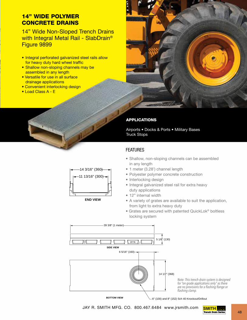
14” WIDE POLYMER CONCRETE DRAINS 14” Wide Non-Sloped Trench Drains with Integral Metal Rail - SlabDrain® Figure 9899
• Integral perforated galvanized steel rails allow for heavy duty hard wheel traffic• Shallow non-sloping channels may be assembled in any length• Versatile for use in all surface drainage applications• Convenient interlocking design • Load Class A - E
APPLICATIONS
Airports • Docks & Ports • Military BasesTruck Stops
FEATURES
• Shallow, non-sloping channels can be assembled in any length• 1 meter (3.28’) channel length• Polyester polymer concrete construction• Interlocking design• Integral galvanized steel rail for extra heavy duty applications• 12” internal width • A variety of grates are available to suit the application, from light to extra heavy duty• Grates are secured with patented QuickLok® boltless locking system
39 3/8" (1 meter)
SIDE VIEW
BOTTOM VIEW
5 1/8" (130)
6" (100) and 8" (152) Sch 40 Knockout/Drillout
END VIEW
14 3/16" (360)
11 13/16" (300)
6 5/16" (160)
14 1/2" (368)
39 3/8" (1 meter)
SIDE VIEW
BOTTOM VIEW
5 1/8" (130)
6" (100) and 8" (152) Sch 40 Knockout/Drillout
END VIEW
14 3/16" (360)
11 13/16" (300)
6 5/16" (160)
14 1/2" (368)
FEATURES
• 14” wide, polyester polymer concrete construction
• Shallow, non-sloping channels
• 1 meter channels can be assembled in any length
• Integral ductile iron rails allow for extra
heavy duty applications.
• Supplied with secured ductile iron slotted grates
JAY R. SMITH MFG. CO. 800.467.6484 www.jrsmith.com48
Note: This trench drain system is designed for “on grade applications only” as there are no provisions for a flashing flange or flashing clamp.
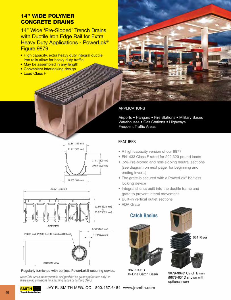
6"(152) and 8"(203) Sch 40 Knockout/Drillout
6"(152) and 8"(203) Sch 40 Knockout/Drillout
14” WIDE POLYMER CONCRETE DRAINS 14” Wide ‘Pre-Sloped’ Trench Drains with Ductile Iron Edge Rail for Extra Heavy Duty Applications - PowerLok®
Figure 9879• High capacity, extra heavy duty integral ductile iron rails allow for heavy duty traffic• May be assembled in any length• Convenient interlocking design• Load Class F
FEATURES
• A high capacity version of our 9877 • EN1433 Class F rated for 202,320 pound loads• .5% Pre-sloped and non-sloping neutral sections (see diagram on next page for beginning and ending inverts)• The grate is secured with a PowerLok® boltless locking device• Integral shunts built into the ductile frame and grate to prevent lateral movement• Built-in vertical outlet sections • ADA Grate
Catch Basins
9879-903DIn-Line Catch Basin 9879-904D Catch Basin
(9879-631D shown withoptional riser)
631 Riser
APPLICATIONS
Airports • Hangars • Fire Stations • Military Bases Warehouses • Gas Stations • HighwaysFrequent Traffic Areas
JAY R. SMITH MFG. CO. 800.467.6484 www.jrsmith.com
SIDE VIEW
BOTTOM VIEW
Regularly furnished with boltless PowerLok® securing device.
49
Note: This trench drain system is designed for “on grade applications only” as there are no provisions for a flashing flange or flashing clamp.

Catch Basin9879-903D CB
Catch Basin9879-903D CB
Catch Basin9879-903D CB
Catch Basin9879-903D CB
Catch Basin9879-904D-CB
Catch Basin9879-904D-CB
Catch Basin9879-904D-CB
Catch Basin9879-904D-CB
131'-3 3/16" (40 meters) Sloped
1 2 3 4 5 6 7 8 9 10 11 12 13 14 15 16 17 18 19 20
9879-UNV(Universal 6"/8"/10" Closing/Inlet/Outlet Cap)
0103
1/2 Meter Neutral Channels
21 22 23 24 25 26 27 28 29 30 31 32 33 34 35 36 37 38 39 40
00 010 020 030 040
0203
0303
0403
1 Meter Neutral Channels
6" and 8" Knockoutsincluded on every 5thchannel.
13 7/8 (352)
11 13/16 (300)
12 13/16 (325) - 20 11/16 (525)
END VIEW
TRENCH DEPTH 9879 SYSTEM
Channel Number
Shallow End Invert
Deep End Invert
Slotted Weight
Lbs.
ADA Weight
Lbs.Inch mm Inch mm Slope9879-00 11.81 300 11.81 300 0.0% 230.2 258.29879-1 11.81 300 12.01 305 0.5% 230.2 258.29879-2 12.01 305 12.20 310 0.5% 231.4 259.49879-3 12.20 310 12.40 315 0.5% 232.7 260.79879-4 12.40 315 12.60 320 0.5% 233.9 261.99879-5 12.60 320 12.80 325 0.5% 235.1 263.19879-6 12.80 325 12.99 330 0.5% 236.4 264.49879-7 12.99 330 13.19 335 0.5% 237.6 265.69879-8 13.19 335 13.39 340 0.5% 238.8 266.89879-9 13.39 340 13.58 345 0.5% 240.0 268.09879-10 13.58 345 13.78 350 0.5% 241.3 269.39879-010 13.78 350 13.78 350 0.0% 241.3 269.39879-103 13.78 350 13.78 350 0.0% 127.9 141.99879-11 13.78 350 13.98 355 0.5% 242.5 270.59879-12 13.98 355 14.17 360 0.5% 243.7 271.79879-13 14.17 360 14.37 365 0.5% 245.0 273.09879-14 14.37 365 14.57 370 0.5% 246.2 274.29879-15 14.57 370 14.76 375 0.5% 247.4 275.49879-16 14.76 375 14.96 380 0.5% 248.7 276.79879-17 14.96 380 15.16 385 0.5% 249.9 277.99879-18 15.16 385 15.35 390 0.5% 251.1 279.19879-19 15.35 390 15.55 395 0.5% 252.4 280.49879-20 15.55 395 15.75 400 0.5% 253.6 281.69879-020 15.75 400 15.75 400 0.0% 253.6 281.69879-203 15.75 400 15.75 400 0.0% 134.9 148.9
TRENCH DEPTH 9879 SYSTEM
Channel Number
Shallow End Invert
Deep End Invert
Slotted Weight
Lbs.
ADA Weight
Lbs.Inch mm Inch mm Slope9879-21 15.75 400 15.94 405 0.5% 254.8 282.89879-22 15.94 405 16.14 410 0.5% 256.1 284.19879-23 16.14 410 16.34 415 0.5% 257.3 285.39879-24 16.34 415 16.54 420 0.5% 258.5 286.59879-25 16.54 420 16.73 425 0.5% 259.7 287.79879-26 16.73 425 16.93 430 0.5% 261.0 289.09879-27 16.93 430 17.13 435 0.5% 262.2 290.29879-28 17.13 435 17.32 440 0.5% 263.4 291.49879-29 17.32 440 17.52 445 0.5% 264.7 292.79879-30 17.52 445 17.72 450 0.5% 265.9 293.99879-030 17.72 450 17.72 450 0.0% 265.9 293.99879-303 17.72 450 17.72 450 0.0% 142.1 156.19879-31 17.72 450 17.91 455 0.5% 267.1 295.19879-32 17.91 455 18.11 460 0.5% 268.4 296.49879-33 18.11 460 18.31 465 0.5% 269.6 297.69879-34 18.31 465 18.50 470 0.5% 270.8 298.89879-35 18.50 470 18.70 475 0.5% 272.1 300.19879-36 18.70 475 18.90 480 0.5% 273.3 301.39879-37 18.90 480 19.09 485 0.5% 274.5 302.59879-38 19.09 485 19.29 490 0.5% 275.7 303.79879-39 19.29 490 19.49 495 0.5% 277.0 305.09879-40 19.49 495 19.69 500 0.5% 278.2 306.29879-040 19.69 500 19.69 500 0.0% 278.2 306.29879-403 19.69 500 19.69 500 0.0% 150.3 164.3
Note: For overall depth of channel add 1.00” to invert depth shown.
14” Wide ‘Pre-Sloped’ Polymer Concrete Trench Drains with Ductile Iron Edge Rail PowerLok® - Figure 9879
JAY R. SMITH MFG. CO. 800.467.6484 www.jrsmith.com50
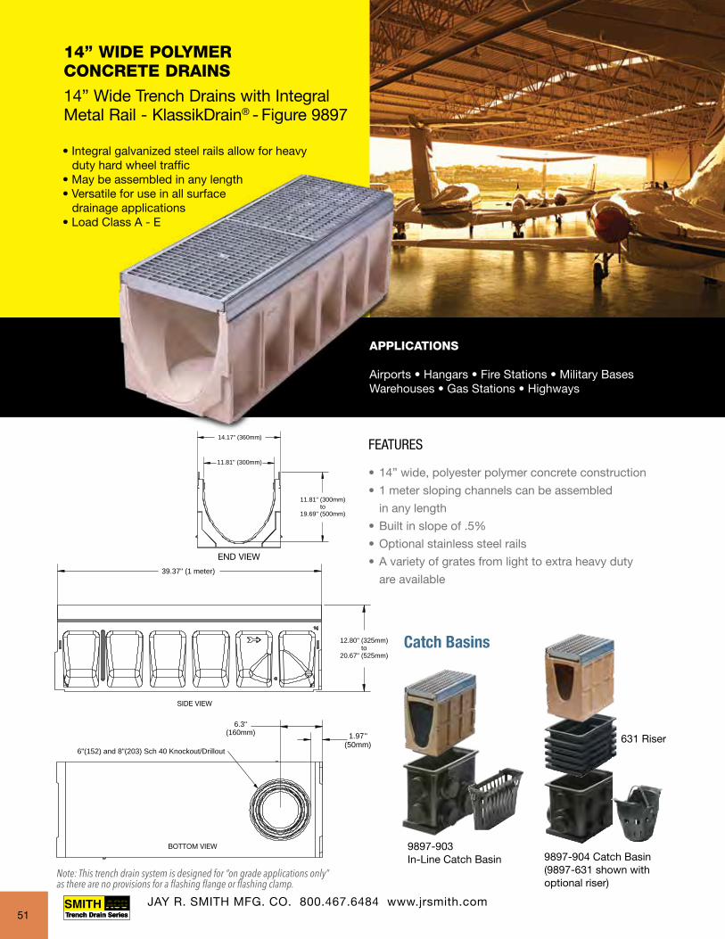
14” WIDE POLYMER CONCRETE DRAINS 14” Wide Trench Drains with Integral Metal Rail - KlassikDrain® - Figure 9897
• Integral galvanized steel rails allow for heavy duty hard wheel traffic• May be assembled in any length• Versatile for use in all surface drainage applications• Load Class A - E
APPLICATIONS
Airports • Hangars • Fire Stations • Military Bases Warehouses • Gas Stations • Highways
FEATURES
• 14” wide, polyester polymer concrete construction
• 1 meter sloping channels can be assembled
in any length
• Built in slope of .5%
• Optional stainless steel rails
• A variety of grates from light to extra heavy duty
are available
Catch Basins
9897-903In-Line Catch Basin 9897-904 Catch Basin
(9897-631 shown withoptional riser)
631 Riser
END VIEW 39.37" (1 meter)
12.80" (325mm)to
20.67" (525mm)
11.81" (300mm)
14.17" (360mm)
11.81" (300mm)to
19.69" (500mm)
1.97"(50mm)
6.3"(160mm)
6"(152) and 8"(203) Sch 40 Knockout/Drillout
JAY R. SMITH MFG. CO. 800.467.6484 www.jrsmith.com
SIDE VIEW
BOTTOM VIEW
39.37" (1 meter)
12.80" (325mm)to
20.67" (525mm)
11.81" (300mm)
14.17" (360mm)
11.81" (300mm)to
19.69" (500mm)
1.97"(50mm)
6.3"(160mm)
6"(152) and 8"(203) Sch 40 Knockout/Drillout
51
Note: This trench drain system is designed for “on grade applications only” as there are no provisions for a flashing flange or flashing clamp.

FEATURES
• 14” wide, polyester polymer concrete construction
• 1 meter sloping channels can be assembled
in any length
• Built in slope of .5%
• Optional stainless steel rails
• A variety of grates from light to extra heavy duty
are available
Catch Basin9897-903 CB
Catch Basin9897-903 CB
Catch Basin9897-903 CB
Catch Basin9897-903 CB
Catch Basin9897-904 CB4
Catch Basin9897-904CB
Catch Basin9897-904 CB
Catch Basin9897-904 CB
131'-3 3/16" (40 meters) Sloped
1 2 3 4 5 6 7 8 9 10 11 12 13 14 15 16 17 18 19 20
9897-UNV6,8,10(Universal Closing/Inlet/Outlet Cap)
0103
1/2 Meter Neutral Channels
21 22 23 24 25 26 27 28 29 30 31 32 33 34 35 36 37 38 39 40
00 010 020 030 040
0203
0303
0403
1 Meter Neutral Channels
6" and 8" Knockoutsincluded on every 5thchannel.
14 (360)
12 (300)
12 13/16 (325) - 20 11/16 (425)
TRENCH DEPTH 9897 SYSTEM
Channel Number
Shallow End Invert
Deep End Invert Weight
Lbs.Inch mm Inch mm Slope9897-00 11.81 300 11.81 300 0.0% 132.69897-1 11.81 305 12.01 305 0.5% 132.69897-2 12.01 310 12.20 310 0.5% 133.89897-3 12.20 315 12.40 315 0.5% 135.09897-4 12.40 320 12.60 320 0.5% 136.29897-5 12.60 325 12.80 325 0.5% 137.49897-6 12.80 330 12.99 330 0.5% 138.69897-7 12.99 335 13.19 335 0.5% 139.89897-8 13.19 340 13.39 340 0.5% 141.09897-9 13.39 345 13.58 345 0.5% 142.29897-10 13.58 350 13.78 350 0.5% 143.49897-010 13.78 350 13.78 350 0.0% 143.49897-103 13.78 350 13.78 350 0.0% 75.39897-11 13.78 355 13.98 355 0.5% 144.69897-12 13.98 360 14.17 360 0.5% 145.89897-13 14.17 365 14.37 365 0.5% 147.09897-14 14.37 370 14.57 370 0.5% 148.29897-15 14.57 375 14.76 375 0.5% 149.49897-16 14.76 380 14.96 380 0.5% 150.69897-17 14.96 385 15.16 385 0.5% 151.89897-18 15.16 390 15.35 390 0.5% 153.09897-19 15.35 395 15.55 395 0.5% 154.29897-20 15.55 400 15.75 400 0.5% 155.49897-020 15.75 400 15.75 400 0.0% 155.49897-203 15.75 400 15.75 400 0.0% 82.3
TRENCH DEPTH 9897 SYSTEM
Channel Number
Shallow End Invert
Deep End Invert Weight
Lbs.Inch mm Inch mm Slope9897-21 15.75 405 15.94 405 0.5% 156.7 9897-22 15.94 410 16.14 410 0.5% 157.99897-23 16.14 415 16.34 415 0.5% 159.19897-24 16.34 420 16.54 420 0.5% 160.39897-25 16.54 425 16.73 425 0.5% 161.59897-26 16.73 430 16.93 430 0.5% 162.79897-27 16.93 435 17.13 435 0.5% 163.99897-28 17.13 440 17.32 440 0.5% 165.19897-29 17.32 445 17.52 445 0.5% 166.39897-30 17.52 450 17.72 450 0.5% 167.59897-030 17.72 450 17.72 450 0.0% 167.59897-303 17.72 450 17.72 450 0.0% 89.59897-31 17.72 455 17.91 455 0.5% 168.79897-32 17.91 460 18.11 460 0.5% 169.99897-33 18.11 465 18.31 465 0.5% 171.19897-34 18.31 470 18.50 470 0.5% 172.39897-35 18.50 475 18.70 475 0.5% 173.59897-36 18.70 480 18.90 480 0.5% 174.79897-37 18.90 485 19.09 485 0.5% 175.99897-38 19.09 490 19.29 490 0.5% 177.19897-39 19.29 495 19.49 495 0.5% 178.39897-40 19.49 500 19.69 500 0.5% 179.59897-040 19.69 500 19.69 500 0.0% 179.59897-403 19.69 500 19.69 500 0.0% 97.7Note: For overall depth of channel add 1.00” to invert depth shown.
14” Wide Polymer Concrete Trench Drains with Integral Metal Rail KlassikDrain® - Figure 9897
JAY R. SMITH MFG. CO. 800.467.6484 www.jrsmith.com52

FEATURES:
• 1 meter (3.28’) precast polyester polymer
concrete construction
• High-strength, lightweight channels feature
interlocking design
• Groove profile for ease of installation and alignment
• Non-sloping bottom
• Supplied with secured grate per specification
39.37" (1 meter)
5.1" (130 mm)4.0" (100 mm)
0.125" (3 mm)5.1" (130 mm)
3.15" (80 mm)
3.15" (80 mm) or4.0" (100 mm)
3.54" (90 mm)1.37" (35 mm)
H100K96739
4” sch. 40 drill-outQuickLok® is a registered trademark of ACO Polymer Products, Inc.
SHALLOW DEPTH POLYMER CONCRETE DRAINS 6” Wide ‘Non-Sloped’ Shallow Trench Drains with Integral Galvanized Edge Rail Figure 9836
APPLICATIONS
Warehousing • Bottling Plants • Industrial Plants Fire Stations • Hangars • Restaurants
39.37" (1 meter)
5.1" (130 mm)4.0" (100 mm)
0.125" (3 mm)5.1" (130 mm)
3.15" (80 mm)
3.15" (80 mm) or4.0" (100 mm)
3.54" (90 mm)1.37" (35 mm)
H100K96739
4” sch. 40 drill-out
• Integrally molded steel edge rail• Reduce installation time and cost with interlocking tongue and groove ends• Ideal for restricted installation depths• May be assembled in any length• Load Class A - E
JAY R. SMITH MFG. CO. 800.467.6484 www.jrsmith.com53
Note: This trench drain system is designed for “on grade applications only” as there are no provisions for a flashing flange or flashing clamp.

39.37" (1 meter)
2.0" (50 mm)1.0" (25 mm)
3.2" (81mm)0.06" (1.5mm)
3.4" (86mm)
3.2" (81 mm)
3.4" (86 mm)
2.0" (50 mm)
1.50” sch. 40 drill-out
NARROW POLYMER CONCRETE DRAINS
3” Wide ‘No Grade’ ‘Narrow’ Trench Drains - Figure 9833
39.37" (1 meter)
2.0" (50 mm)1.0" (25 mm)
3.2" (81mm)0.06" (1.5mm)
3.4" (86mm)
3.2" (81 mm)
3.4" (86 mm)
2.0" (50 mm)
1.50” sch. 40 drill-out
• High strength polyester polymer conctete construction• Ease of assembly in any length with interlocking tongue and groove ends• Reduces installation time and cost• Load class A - C
FEATURES:
• 1 meter (3.28’) precast polyester polymer
concrete construction
• High-strength, lightweight channels feature
interlocking design
• Non-sloping radius bottom channel
• Integrally molded galvanized steel edge rail
• Supplied with grate per specification,
see submittal for details
APPLICATIONS
Swimming Pools • Pedestrian Areas • Sidewalks
JAY R. SMITH MFG. CO. 800.467.6484 www.jrsmith.com54
Note: This trench drain system is designed for “on grade applications only” as there are no provisions for a flashing flange or flashing clamp.

QuickLok®/ PowerLok® Details
The QuickLok® grate locking system is designed to improve access to the trench drain for cleaning and maintenance. With QuickLok®, removing gratelockdown bolts is in the past.
FEATURES
• Preassembled to the grates
• Contractor places QuickLok® locking bar in channel
• Locking bar remains in place by tension side grips
• Optional QuickLok® grate removal tool
QuickLok® is a registered trademark of ACO Polymer Products, Inc.
QuickLok® Boltless Locking System
1. 2.
3. 4.
There is no need for tools to fasten the grate into the channel. The grate snaps into place with a quick impact.
The locking force is sufficient to hold grates in place up to load Class E.
Insert locking bar into channel’s locking pockets and secure by inserting shims on both sides.
Patented PowerLok® Boltless Locking System
1. 2.
3. 4.
To lock grate in place, insert -GRT tool into clip and pull.
To remove grate, place the -GRT tool between the grate clip and the trench rail and rotate clockwise. Clip will release easily.
Pin
Grate
Lock Lob
Spring Clip
Lock Bar
QuickLok®
assemblycomponents
Cross section withQuickLok®
JAY R. SMITH MFG. CO. 800.467.6484 www.jrsmith.com55

9857 Oil Separator, 9846 Sump Boxes and 9812 Series Catch Basins
"L"*
"D"*"H"
"J" Sq.
"K"
CAST IRON FRAME
*Specify Inlet and Outlet Diameter and Invert Location
9812 Catch BasinsThe 9812 Series Catch Basins are (9812-660-CB12) 1’-3” x 2’ x 2’-3” deep and (9812-880-CB24) 2’ x 2’-3” x 2’-4” deep units. These catch basins can be used in conjunction with the 9812 Fiberglass Trench System. Knockouts to accept trench inlets or plumbing connections are easily fabricated on the job site. All units come standard with a secured, slotted ductile iron grate and coated steel frame, as well as installation brackets.
9812-660-CB12 9812-880-CB24
The Jay R. Smith Mfg. Co.® Drainage Systems 9846 Sump Boxes are preassembled modular units which offer solutions to many applications. Well-suited for high capacity flow rates, solids and sludge handling, chemical containment, and pump housing, the sump boxes are available in a range of sizes from 2’ x 2’ x 2’ to 4’ x 4’x 4’.
These polymer concrete sump boxes are easily adapted for uses with any of the Channel Slope Precast Polymer Concrete Systems. Upon specification, knockouts can be custom fabricated for pipe connections. Regularly furnished with cast iron frame and loose set cast iron slotted grate. Jay R. Smith Mfg. Co. Drainage Systems’ trained staff will assist in specifying the 9846 Sump Box to meet your special needs.
Figure Inside Dimension of Capacity Weight w/o “H” “K” “J” SQ Number Sump Box Cover w/Frame w/out Frame Outside DIM
9846 2’ x 2’ (610mm x 610mm) 43.3 164 197 (90 kg) 26.75 (680mm) 24.00 (610mm) 27.88 (708mm) 9847 3’ x 3’ (914mm x 914mm) 161.2 610 467 (212 kg) 38.50 (978mm) 35.75 (909mm) 40.50 (1029mm) 9848 4’ x 4’ (1219mm x 1219mm) 475 1798 808 (368 kg) 50.38 (1280 mm) 48.75 (1238mm) 51.38 (1305mm)
Gallons Liters
9846 Sump Boxes
Support ChannelsWelded to Bottom of Cover
3" x 1.5" x .35" thick(4 Req'd)
26"
49"
76"
Inlet(4" Dia. Sch.
40 PVC)
Outlet(4" Dia. Sch.
40 PVC)
Cover Plates: 1/4" steel diamond plate withcarbonic zinc coating (2 Req'd)
Cover plates to withstand class A load rating
12"InvertElevation
12"
10"
9857 Oil SeparatorThe Jay R. Smith Mfg. Co.® Drainage Systems 9857 Oil Separator effectively helps to separate oils, gases, acids, sand, food remains and sludges from wastewater. It can be utilized in a variety of applications – auto body shops, gas stations, and manufacturing and food processing plants. The 9857 is a manufactured double-basin 220 gallon capacity design from polymer concrete. All PVC 4” piping and cover plates are provided.
Smith Drainage Systems will furnish engineering and installation draw-ings for your review. Technical assistance is also available for installation, which normally is accomplished in a few hours.
1/4” steel diamond cover plates with carbonic zinc coatings are standard for the 9857. The load rating is Class A, or light Duty, for slow speed pneumatic tire traffic only, gross vehicle weight of 3500 lbs – 70PSI.
Available options include holes for venting and Heavy Duty load class “C” covers.
JAY R. SMITH MFG. CO. 800.467.6484 www.jrsmith.com JAY R. SMITH MFG. CO. 800.467.6484 www.jrsmith.com56
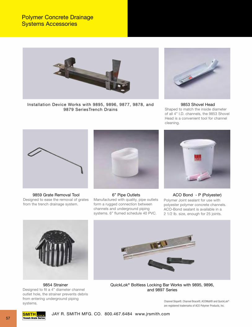
FIBERGLASS TRENCH DRAINS10” TO 12” WIDE - 9812 - 9872 SERIES
Polymer Concrete Drainage Systems Accessories
Channel Slope®, Channel Brace®, ACOWall® and QuickLok®
are registered trademarks of ACO Polymer Products, Inc.
6” Pipe OutletsManufactured with quality, pipe outlets form a rugged connection between channels and underground pipingsystems. 6” flumed schedule 40 PVC.
9853 Shovel HeadShaped to match the inside diameter of all 4” I.D. channels, the 9853 Shovel Head is a convenient tool for channel cleaning.
9854 StrainerDesigned to fit a 4” diameter channel outlet hole, the strainer prevents debris from entering underground pipingsystems.
9859 Grate Removal ToolDesigned to ease the removal of grates from the trench drainage system.
Polymer Joint sealant for use with polyester polymer concrete channels. ACO-Bond sealant is available in a2 1/2 lb. size, enough for 25 joints.
ACO Bond - P (Polyester)
QuickLok® Boltless Locking Bar Works with 9895, 9896,and 9897 Series
Installation Device Works with 9895, 9896, 9877, 9878, and 9879 SeriesTrench Drains
JAY R. SMITH MFG. CO. 800.467.6484 www.jrsmith.com57

FIBERGLASS TRENCH DRAINS10” TO 12” WIDE - 9812 - 9872 SERIES
Figure Number 9812 - 10” wide high capacity pre-sloped fiberglass trench drains
Figure Number 9872 - 12” wide high capacity pre-sloped fiberglass trench drains
• Engineered solutions for high capacity and advanced hydraulic requirements.
• High strength, light weight, and corrosion-resistant.
• Quick evacuation of large volumes of standing or surface liquids (dependent
on grate selection).
• 8” internal width and built in slope of 1%.
• 12 sloped channels and 4 neutral channels are each nine feet in length and 4 neutral
channels are three feet in length. Channel depth varies from 6.88 to 20.38 inches.
• Ideal for rapid installation.
• Corrosion-resistant polyester fiberglass.
Figure Number 9812 Figure Number 9872
58

10” WIDE FIBERGLASS 10” Wide High Capacity Pre-Sloped Trench Drains - Figure 9812
APPLICATIONS
Industrial Plants • Warehousing • Bottling Plants Food Service • Loading Docks
• Durable fiberglass construction• High strength, lightweight and corrosion-resistant• Convenient pre-sloped and non-sloping channels• Internal width of 8”• Grate seat 10” wide• Load Class C and E
FEATURES• Polyester fiberglass is standard; vinylester fiberglass optional for additional corrosion resistance• 9’ in length• Channel depth from 6.88” to 20.38” (see chart next page)• Duco coated welded steel frame support system with concrete anchors (one pair every 18 inches)• Painted, fabricated steel angle in Z pattern• Rebar/all thread elevation setting option built into frame• Push fit frame and channel assembly • Galvanized steel frame optional• Stainless steel frame optional• Wide variety of grate options (see page 68)• Supplied with secured load class “E” ductile iron slotted grate• Outlets can be located anywhere along bottom of channel
10.1"(257 mm)
9'(2743 mm)
18"(457 mm)
Fiberglass ChannelInterlocking Male/Female
End Profiles
4'', 6'', or 8'' Vertical Outlet Saddle
8"(203 mm)
Coated, Galvanized orStainless Steel Frame withInstallation Brackets and
Concrete Anchors
4'' sch. 40 Inlet/Outlet End Cap6'' sch. 40 Inlet/Outlet End Cap8'' sch. 40 Inlet/Outlet End Cap
4'', 6'', or 8'' Outlet Cap.Guide Lines Aid Cutting
Male End Cap Fits Outside Male/Deep End
of Channel
Female End Cap Fits Inside Female/Shallow End
of Channel. Has Choiceof Coated Steel, StainlessSteel, or Galvanized Steel
End Frames.
ACCESSORY COMPONENTS INCLUDE:• Catch basins• Universal end caps• Universal outlet caps • 4”, 6”and 8” bottom outlets to provide a high degree of flexibility when designing the system • Custom outlets are available upon customer request
CROSS SECTION DETAIL
10.1"(257mm)
6.88" - 20.38"(175mm) - (518mm)
FRP Channel
8"(205mm)
17.10"434mm
Welded Installation Device For Rebar Support 4 per Frame(Rebar posts by others)
Patent No. 5,066,165
JAY R. SMITH MFG. CO. 800.467.6484 www.jrsmith.com59

JAY R. SMITH MFG. CO. 800.467.6484 www.jrsmith.com
FEATURES• Polyester fiberglass is standard; vinylester fiberglass optional for additional corrosion resistance• 9’ in length• Channel depth from 6.88” to 20.38” (see chart next page)• Duco coated welded steel frame support system with concrete anchors (one pair every 18 inches)• Painted, fabricated steel angle in Z pattern• Rebar/all thread elevation setting option built into frame• Push fit frame and channel assembly • Galvanized steel frame optional• Stainless steel frame optional• Wide variety of grate options (see page 68)• Supplied with secured load class “E” ductile iron slotted grate• Outlets can be located anywhere along bottom of channel
JAY R. SMITH MFG. CO. 800.467.6484 www.jrsmith.com
10.1"(257mm)
6.88" - 20.38"
26.60"
(175mm) - (518mm)FRP Channel
8"(205mm)
880Catch Basin
660Catch Basin
17.10"434mm
Welded Installation Device For Rebar Support 4 per Frame(Rebar posts by others)
(676mm)
14.00" x 24.00"(356mm x 610mm)
27.69"(686mm)
27.00" Sq.(686mm)
801 802 803 804 805 806 807 808 809 810 811 812
803N
803N3
806N
806N3
809N
809N3
812N
812N3
Bottom Outlet4", 6" or 8" DIA.
(V4, V6, V8)
End Depth20.38"
(518mm)
End Depth6.88"
(175mm)
108' - 0"(12 Channel Sections)
1.04% Slope
InletEnd Cap
4", 6" or 8"(I4, I6, I8)
End Cap4", 6" or 8"
(H4, H6, H8)
Outlet
Fits AllChannels
Fits Channels802 Thru 812
Fits AllChannels
Shallow End Cap(-ES)
Deep End Cap(-ED)
9' Neutral Channel
3' Neutral Channel
**
**
Trench Depth 9812 SystemChannel Number
Shallow End Invert*
Deep End Invert*
Holding Capacity
in. mm in. mm (gallons)9812-801 8.00 203 8.00 203 18.379812-802 8.00 203 9.13 232 22.589812-803 9.13 232 10.25 260 26.79
** 9812-803N 10.25 260 10.25 260 28.80*** 9812-803N3 10.25 260 10.25 260 9.60
9812-804 10.25 260 11.38 289 31.009812-805 11.38 289 12.50 317 35.219812-806 12.50 317 13.63 346 39.42
** 9812-806N 13.63 346 13.63 346 41.50*** 9812-806N3 13.63 346 13.63 346 13.83
9812-807 13.63 346 14.75 374 43.639812-808 14.75 374 15.88 403 47.849812-809 15.88 403 17.00 432 52.05
** 9812-809N 17.00 432 17.00 432 54.10*** 9812-809N3 17.00 432 17.00 432 18.00
9812-810 17.00 432 18.13 460 56.269812-811 18.13 460 19.25 489 60.479812-812 19.25 489 20.38 517 64.68
** 9812-812N 20.38 517 20.38 517 66.76*** 9812-812N3 20.38 517 20.38 517 22.25
*The end inverts include grate frame.** 9’ Long Neutral Channel
*** 3’ Long Neutral Channel
Outlet Cap Flow Rates
Outlet Size
Channel Invert Depth
GPM CFS
4” Vertical 801 7.88 (200) 154 0.344” Vertical 812 20.25 (514) 246 0.546” Vertical 801 7.88 (200) 346 0.776” Vertical 812 20.25 (514) 553 1.238” Vertical 801 7.88 (200) 616 1.378” Vertical 812 20.25 (514) 982 2.184” Horizontal 802 9.00 (229) 145 0.334” Horizontal 812 20.25 (514) 233 0.546” Horizontal 803 10.13 (257) 330 0.766” Horizontal 812 20.25 (514) 510 1.178” Horizontal 805 12.38 (314) 635 1.468” Horizontal 812 20.25 (514) 880 2.03
Dim’s in ( ) are mm.
10” Wide Fiberglass High Capacity Pre-Sloped Trench Drains Figure 9812
60
Note: This trench drain system is designed for “on grade applications only” as there are no provisions for a flashing flange or flashing clamp.

12” WIDE FIBERGLASS 12” Wide High Capacity Pre-Sloped Trench Drains - Figure 9872
• High capacity channels reduce installation time and labor• May be assembled in any length utilizing 9-foot channels• Durable fiberglass construction• High strength, light weight and corrosion-resistant • 12” wide grate seat area• Load Class E
APPLICATIONS
Industrial Plants • Warehousing • Bottling Plants Food Service • Loading Docks
FEATURES
• 9’ long, high-capacity channel
• Polyester fiberglass construction
• Sloped radius bottom surface
• Duco coated welded steel frame support system
with concrete anchors (one pair every 18 inches)
• Supplied with secured load class “E” ductile iron
slotted grate
12.19"(310mm)
7.06" - 20.56"(179mm) - (522mm)
FRP Channel
8"(205mm)
19.56"497mm
Welded Installation Device For Rebar Support 4 per Frame(Rebar posts by others)
801 802 803 804 805 806 807 808 809 810 811 812
803N
803N3
806N
806N3
809N
809N3
812N
812N3
Bottom Outlet4", 6" or 8" DIA.
(V4, V6, V8)
End Depth20.56"
(522mm)
End Depth7.06"
(179mm)
108' - 0"(12 Channel Sections)
1.04% Slope
InletEnd Cap
4", 6" or 8"(I4, I6, I8)
End Cap4", 6" or 8"
(H4, H6, H8)
Outlet
Fits AllChannels
Fits Channels802 Thru 812
Fits AllChannels
Shallow End Cap(-ES)
Deep End Cap(-ED)
9' Neutral Channel
3' Neutral Channel
880Catch Basin
27.69"(686mm)
27.00" Sq.(686mm)
**
26.60"
660Catch Basin
(676mm)
14.00" x 24.00"(356mm x 610mm)
**
CROSS SECTION DETAIL
JAY R. SMITH MFG. CO. 800.467.6484 www.jrsmith.com
12.1"(307 mm)
9'(2743 mm)
18"(457 mm)
Fiberglass ChannelInterlocking Male/Female
End Profiles
4'', 6'', or 8'' Vertical Outlet Saddle
8"(203 mm)
Coated, Galvanized orStainless Steel Frame withInstallation Brackets and
Concrete Anchors
4'' sch. 40 Inlet/Outlet End Cap6'' sch. 40 Inlet/Outlet End Cap8'' sch. 40 Inlet/Outlet End Cap
4'', 6'', or 8'' Outlet Cap.Guide Lines Aid Cutting
Male End Cap Fits Outside Male/Deep End
of Channel
Female End Cap Fits Inside Female/Shallow End
of Channel. Has Choiceof Coated Steel, StainlessSteel, or Galvanized Steel
End Frames.
Patent No. 5,066,165
ACCESSORY COMPONENTS INCLUDE:
• Catch basins• Universal end caps• Universal outlet caps • 4”, 6”and 8” bottom outlets to provide a high degree of flexibility when designing the system • Custom outlets are available upon customer request.
GRATE
Ductile Iron Slotted GrateLength: 18 inches
EXTRA HEAVY DUTYEN1433 Class E: 135,000 lbs - 2,788 psi. For commercial solid tire trafficpatterns, forkliftsand impacts from steel struts or metal wheels.
61

801 802 803 804 805 806 807 808 809 810 811 812
803N
803N3
806N
806N3
809N
809N3
812N
812N3
Bottom Outlet4", 6" or 8" DIA.
(V4, V6, V8)
End Depth20.56"
(522mm)
End Depth7.06"
(179mm)
108' - 0"(12 Channel Sections)
1.04% Slope
InletEnd Cap
4", 6" or 8"(I4, I6, I8)
End Cap4", 6" or 8"
(H4, H6, H8)
Outlet
Fits AllChannels
Fits Channels802 Thru 812
Fits AllChannels
Shallow End Cap(-ES)
Deep End Cap(-ED)
9' Neutral Channel
3' Neutral Channel
880Catch Basin
27.69"(686mm)
27.00" Sq.(686mm)
**
26.60"
660Catch Basin
(676mm)
14.00" x 24.00"(356mm x 610mm)
**
Outlet Cap Flow Rates
Outlet Size
Channel Invert Depth
GPM CFS
4” Vertical 801 8.06 (205) 154 0.344” Vertical 812 20.43 (519) 246 0.546” Vertical 801 8.06 (205) 346 0.776” Vertical 812 20.43 (519) 553 1.238” Vertical 801 8.06 (205) 616 1.378” Vertical 812 20.43 (519) 982 2.184” Horizontal 802 9.18 (233) 145 0.334” Horizontal 812 20.43 (519) 233 0.546” Horizontal 803 10.31 (262) 330 0.766” Horizontal 812 20.43 (519) 510 1.178” Horizontal 805 12.56 (319) 635 1.468” Horizontal 812 20.43 (519) 880 2.03
Dim’s in ( ) are mm.
Trench Depth 9872 SystemChannel Number
Shallow End Invert*
Deep End Invert*
Holding Capacity
in. mm in. mm (gallons)9872-801 8.19 208 8.19 208 18.379872-802 8.19 208 9.31 237 22.589872-803 9.31 237 10.43 265 26.79
** 9872-803N 10.43 265 10.43 265 28.80*** 9872-803N3 10.43 265 10.43 265 9.60
9872-804 10.43 265 11.56 294 31.009872-805 11.56 294 12.68 322 35.219872-806 12.68 322 13.81 351 39.42
** 9872-806N 13.81 351 13.81 351 41.50*** 9872-806N3 13.81 351 13.81 351 13.83
9872-807 13.81 351 14.93 379 43.639872-808 14.93 379 16.06 408 47.849872-809 16.06 408 17.18 436 52.05
** 9872-809N 17.18 436 17.18 436 54.10*** 9872-809N3 17.18 436 17.18 436 18.00
9872-810 17.18 436 18.31 465 56.269872-811 18.31 465 19.43 494 60.479872-812 19.43 494 20.56 522 64.68
** 9872-812N 20.56 522 20.56 522 66.76*** 9872-812N3 20.56 522 20.56 522 22.25
*The end inverts include grate frame.** 9’ Long Neutral Channel
*** 3’ Long Neutral Channel
12” Wide Fiberglass High Capacity Pre-Sloped Trench Drains Figure 9872
JAY R. SMITH MFG. CO. 800.467.6484 www.jrsmith.com62
Note: This trench drain system is designed for “on grade applications only” as there are no provisions for a flashing flange or flashing clamp.

GRATES FOR 6”, 10”, AND 14”TRENCH DRAINS
63

JAY R. SMITH MFG. CO. 800.467.6484 www.jrsmith.com
GRATES FOR 6”, 10”, AND 14”TRENCH DRAINS
Load Rating andApplication Guidelines
Load Rating and Application Guidelines
Load Class A: Light DutyLight Duty, EN1433 Class A - 3,500 lbs - 70 psifor pedestrian, wheelchair and bicycle traffic.
Load Class B: Light DutyLight Duty, EN1433 Class B - 28,000 lbs - 580 psifor pedestrian, wheelchair, bicycle traffic and cars.
Load Class C: Heavy DutyHeavy Duty, EN1433 Class C - 56,000 lbs.1,162 psi for commercial pneumatic tire traffic patterns, forklifts, and tractor trailers.
Load Class C HS20 Load traffic - When constant cyclical traffic specify the 9931 frame.
Load Class E: Extra Heavy DutyExtra Heavy Duty, EN1433 Class E - 135,000 lbs. - 2,788 psi - for commercial solid tire traffic patterns, forklifts, impacts from steel struts or metal wheels, and commercial aircraft.
Load Class F: Special Heavy DutyExtra Heavy Duty, EN1433/EN 1433 Load Class F: 202,320 lbs - 4182 psi. For aircraft runways, docks, heavy fork trucks, and heavy wheel loads.
See pages 65 - 69 for appropriate grating for load class requirements.
64
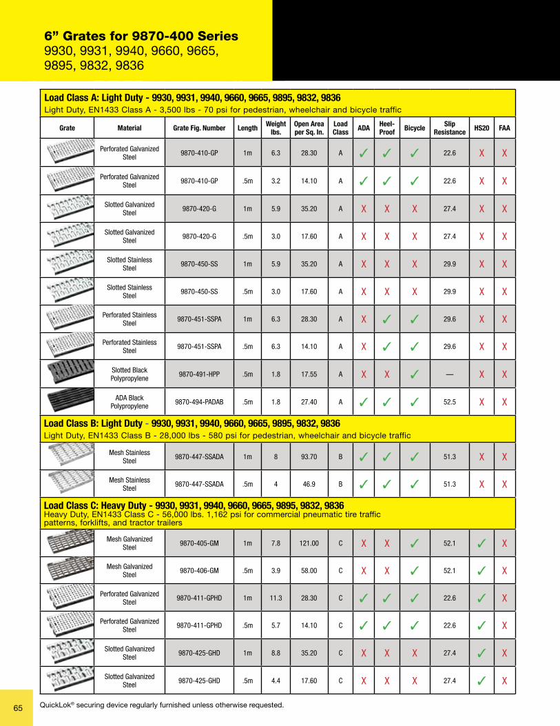
Load Class A: Light Duty - 9930, 9931, 9940, 9660, 9665, 9895, 9832, 9836Light Duty, EN1433 Class A - 3,500 lbs - 70 psi for pedestrian, wheelchair and bicycle traffic
Grate Material Grate Fig. Number Length Weight lbs.
Open Area per Sq. In.
Load Class ADA Heel-
Proof Bicycle SlipResistance HS20 FAA
Perforated Galvanized Steel 9870-410-GP 1m 6.3 28.30 A ✓ ✓ ✓ 22.6 X X
Perforated Galvanized Steel 9870-410-GP .5m 3.2 14.10 A ✓ ✓ ✓ 22.6 X X
Slotted Galvanized Steel 9870-420-G 1m 5.9 35.20 A X X X 27.4 X X
Slotted Galvanized Steel 9870-420-G .5m 3.0 17.60 A X X X 27.4 X X
Slotted StainlessSteel 9870-450-SS 1m 5.9 35.20 A X X X 29.9 X X
Slotted StainlessSteel 9870-450-SS .5m 3.0 17.60 A X X X 29.9 X X
Perforated Stainless Steel 9870-451-SSPA 1m 6.3 28.30 A X ✓ ✓ 29.6 X X
Perforated Stainless Steel 9870-451-SSPA .5m 6.3 14.10 A X ✓ ✓ 29.6 X X
Slotted BlackPolypropylene 9870-491-HPP .5m 1.8 17.55 A X X ✓ — X X
ADA BlackPolypropylene 9870-494-PADAB .5m 1.8 27.40 A ✓ ✓ ✓ 52.5 X X
Load Class B: Light Duty - 9930, 9931, 9940, 9660, 9665, 9895, 9832, 9836Light Duty, EN1433 Class B - 28,000 lbs - 580 psi for pedestrian, wheelchair and bicycle traffic
Mesh StainlessSteel 9870-447-SSADA 1m 8 93.70 B ✓ ✓ ✓ 51.3 X X
Mesh StainlessSteel 9870-447-SSADA .5m 4 46.9 B ✓ ✓ ✓ 51.3 X X
Load Class C: Heavy Duty - 9930, 9931, 9940, 9660, 9665, 9895, 9832, 9836 Heavy Duty, EN1433 Class C - 56,000 lbs. 1,162 psi for commercial pneumatic tire traffic patterns, forklifts, and tractor trailers
Mesh GalvanizedSteel 9870-405-GM 1m 7.8 121.00 C X X ✓ 52.1 ✓ X
Mesh GalvanizedSteel 9870-406-GM .5m 3.9 58.00 C X X ✓ 52.1 ✓ X
Perforated Galvanized Steel 9870-411-GPHD 1m 11.3 28.30 C ✓ ✓ ✓ 22.6 ✓ X
Perforated Galvanized Steel 9870-411-GPHD .5m 5.7 14.10 C ✓ ✓ ✓ 22.6 ✓ X
Slotted Galvanized Steel 9870-425-GHD 1m 8.8 35.20 C X X X 27.4 ✓ X
Slotted Galvanized Steel 9870-425-GHD .5m 4.4 17.60 C X X X 27.4 ✓ X
6” Grates for 9870-400 Series9930, 9931, 9940, 9660, 9665,9895, 9832, 9836
65 QuickLok® securing device regularly furnished unless otherwise requested.
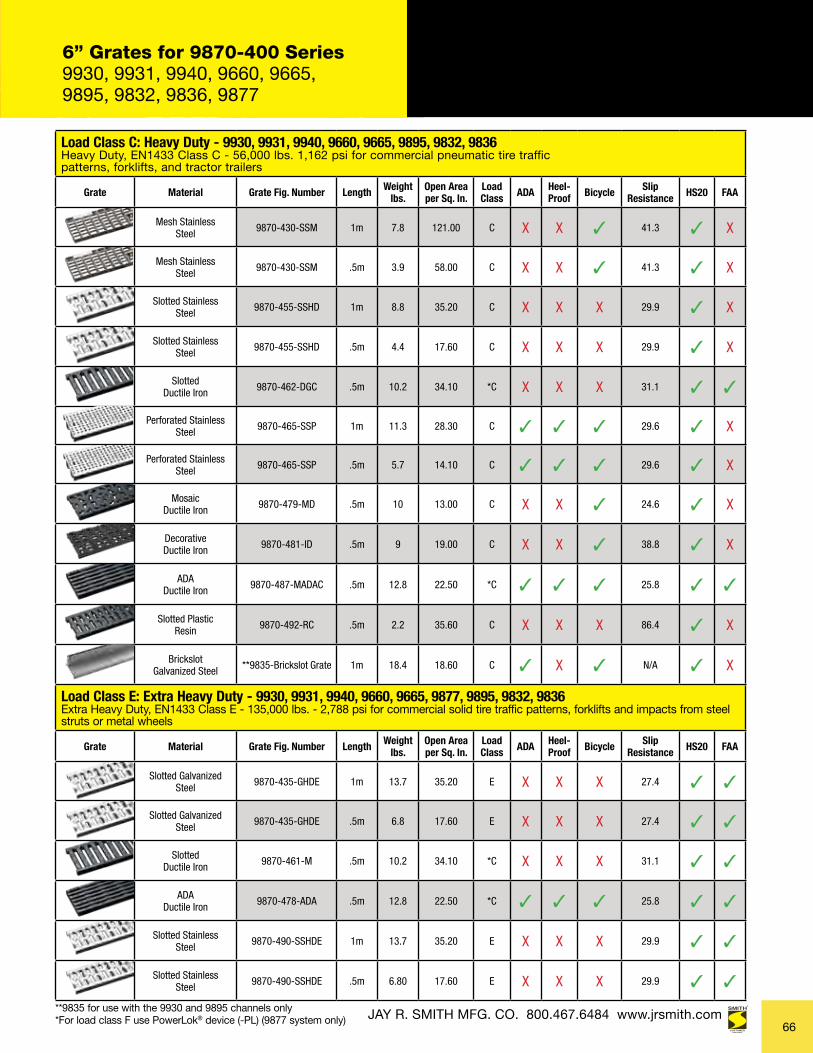
JAY R. SMITH MFG. CO. 800.467.6484 www.jrsmith.com**9835 for use with the 9930 and 9895 channels only
Load Class C: Heavy Duty - 9930, 9931, 9940, 9660, 9665, 9895, 9832, 9836 Heavy Duty, EN1433 Class C - 56,000 lbs. 1,162 psi for commercial pneumatic tire traffic patterns, forklifts, and tractor trailers
Grate Material Grate Fig. Number Length Weight lbs.
Open Area per Sq. In.
Load Class ADA Heel-
Proof Bicycle SlipResistance HS20 FAA
Mesh StainlessSteel 9870-430-SSM 1m 7.8 121.00 C X X ✓ 41.3 ✓ X
Mesh StainlessSteel 9870-430-SSM .5m 3.9 58.00 C X X ✓ 41.3 ✓ X
Slotted StainlessSteel 9870-455-SSHD 1m 8.8 35.20 C X X X 29.9 ✓ X
Slotted StainlessSteel 9870-455-SSHD .5m 4.4 17.60 C X X X 29.9 ✓ X
SlottedDuctile Iron 9870-462-DGC .5m 10.2 34.10 *C X X X 31.1 ✓ ✓
Perforated Stainless Steel 9870-465-SSP 1m 11.3 28.30 C ✓ ✓ ✓ 29.6 ✓ X
Perforated Stainless Steel 9870-465-SSP .5m 5.7 14.10 C ✓ ✓ ✓ 29.6 ✓ X
MosaicDuctile Iron 9870-479-MD .5m 10 13.00 C X X ✓ 24.6 ✓ X
DecorativeDuctile Iron 9870-481-ID .5m 9 19.00 C X X ✓ 38.8 ✓ X
ADADuctile Iron 9870-487-MADAC .5m 12.8 22.50 *C ✓ ✓ ✓ 25.8 ✓ ✓
Slotted PlasticResin 9870-492-RC .5m 2.2 35.60 C X X X 86.4 ✓ X
BrickslotGalvanized Steel **9835-Brickslot Grate 1m 18.4 18.60 C ✓ X ✓ N/A ✓ X
Load Class E: Extra Heavy Duty - 9930, 9931, 9940, 9660, 9665, 9877, 9895, 9832, 9836 Extra Heavy Duty, EN1433 Class E - 135,000 lbs. - 2,788 psi for commercial solid tire traffic patterns, forklifts and impacts from steel struts or metal wheels
Grate Material Grate Fig. Number Length Weight lbs.
Open Area per Sq. In.
Load Class ADA Heel-
Proof Bicycle SlipResistance HS20 FAA
Slotted Galvanized Steel 9870-435-GHDE 1m 13.7 35.20 E X X X 27.4 ✓ ✓
Slotted Galvanized Steel 9870-435-GHDE .5m 6.8 17.60 E X X X 27.4 ✓ ✓
SlottedDuctile Iron 9870-461-M .5m 10.2 34.10 *C X X X 31.1 ✓ ✓
ADADuctile Iron 9870-478-ADA .5m 12.8 22.50 *C ✓ ✓ ✓ 25.8 ✓ ✓
Slotted StainlessSteel 9870-490-SSHDE 1m 13.7 35.20 E X X X 29.9 ✓ ✓
Slotted StainlessSteel 9870-490-SSHDE .5m 6.80 17.60 E X X X 29.9 ✓ ✓
6” Grates for 9870-400 Series9930, 9931, 9940, 9660, 9665,9895, 9832, 9836, 9877
66*For load class F use PowerLok® device (-PL) (9877 system only)
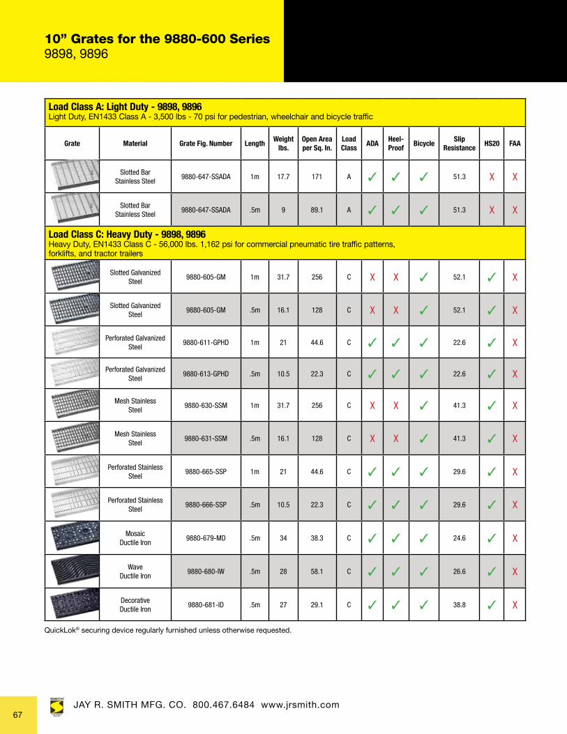
Load Class A: Light Duty - 9898, 9896 Light Duty, EN1433 Class A - 3,500 lbs - 70 psi for pedestrian, wheelchair and bicycle traffic
Grate Material Grate Fig. Number LengthWeight
lbs.Open Area per Sq. In.
Load Class
ADAHeel- Proof
BicycleSlip
ResistanceHS20 FAA
Slotted Bar Stainless Steel
9880-647-SSADA 1m 17.7 171 A ✓ ✓ ✓ 51.3 X X
Slotted Bar Stainless Steel
9880-647-SSADA .5m 9 89.1 A ✓ ✓ ✓ 51.3 X X
Load Class C: Heavy Duty - 9898, 9896 Heavy Duty, EN1433 Class C - 56,000 lbs. 1,162 psi for commercial pneumatic tire traffic patterns, forklifts, and tractor trailers
Slotted Galvanized Steel
9880-605-GM 1m 31.7 256 C X X ✓ 52.1 ✓ X
Slotted Galvanized Steel
9880-605-GM .5m 16.1 128 C X X ✓ 52.1 ✓ X
Perforated Galvanized Steel
9880-611-GPHD 1m 21 44.6 C ✓ ✓ ✓ 22.6 ✓ X
Perforated Galvanized Steel
9880-613-GPHD .5m 10.5 22.3 C ✓ ✓ ✓ 22.6 ✓ X
Mesh StainlessSteel
9880-630-SSM 1m 31.7 256 C X X ✓ 41.3 ✓ X
Mesh StainlessSteel
9880-631-SSM .5m 16.1 128 C X X ✓ 41.3 ✓ X
Perforated Stainless Steel
9880-665-SSP 1m 21 44.6 C ✓ ✓ ✓ 29.6 ✓ X
Perforated Stainless Steel
9880-666-SSP .5m 10.5 22.3 C ✓ ✓ ✓ 29.6 ✓ X
MosaicDuctile Iron
9880-679-MD .5m 34 38.3 C ✓ ✓ ✓ 24.6 ✓ X
WaveDuctile Iron
9880-680-IW .5m 28 58.1 C ✓ ✓ ✓ 26.6 ✓ X
DecorativeDuctile Iron
9880-681-ID .5m 27 29.1 C ✓ ✓ ✓ 38.8 ✓ X
10” Grates for the 9880-600 Series9898, 9896
JAY R. SMITH MFG. CO. 800.467.6484 www.jrsmith.com67
QuickLok® securing device regularly furnished unless otherwise requested.

JAY R. SMITH MFG. CO. 800.467.6484 www.jrsmith.com
Load Class E: Extra Heavy Duty - 9878, 9806, 9898, 9896 Extra Heavy Duty, EN1433 Class E - 135,000 lbs. - 2,788 psi for commercial solid tire traffic patterns, forklifts and impacts from steel struts or metal wheels
Grate Material Grate Fig. Number LengthWeight
lbs.Open Area per Sq. In.
Load Class
ADAHeel- Proof
BicycleSlip
ResistanceHS20 FAA
SlottedDuctile Iron
9880-661-M .5m 30.8 81.9 *E X X ✓ 59.9 ✓ X
WaveDuctile Iron
9880-678-MADA .5m 22 60.6 *E ✓ ✓ ✓ 25.8 ✓ X
10” Grates for the 9880-600 Series9878, 9806, 9898, 9896
10” Grates for the 9890-800 Series9812
Load Class C: Heavy Duty - 9812 Heavy Duty, EN1433 Class C - 56,000 lbs. 1,162 psi for commercial pneumatic tire traffic patterns, forklifts, and tractor trailers
Grate Material Grate Fig. Number LengthWeight
lbs.Open Area per Sq. In.
Load Class
ADAHeel- Proof
BicycleSlip
ResistanceHS20 FAA
Bar Galvanized Steel 9812-G 1m 35.2 263.50 C X X ✓ 54.3 ✓ X
Bar Stainless Steel 9812-SS 1m 35.2 263.50 C X X ✓ 61 ✓ X
Load Class E: Extra Heavy Duty - 9812 Extra Heavy Duty, EN1433 Class E - 135,000 lbs. - 2,788 psi for commercial solid tire traffic patterns, forklifts and impacts from steel struts or metal wheels
SlottedDuctile Iron
9812-M .5m 25.2 61.25 E X X X 29 ✓ X
ADA SlottedDuctile Iron
9812-MADA .5m 28.2 42.00 E ✓ ✓ ✓ 31.9 ✓ X
68
QuickLok® securing device regularly furnished unless otherwise requested.
*For load class F use the PowerLok® device (-PL) (9806 & 9878 systems only)

14” Grates for the 9890-800 Series9807, 9899, 9879, 9897
Load Class A: Light Duty - 9897, 9899 Light Duty, EN1433 Class A - 3,500 lbs - 70 psi for pedestrian, wheelchair and bicycle traffic
Grate Material Grate Fig. Number LengthWeight
lbs.Open Area per Sq. In.
Load Class
ADAHeel- Proof
BicycleSlip
ResistanceHS20 FAA
Mesh StainlessSteel 9890-847-SSADA 1m 28.6 238.2 A ✓ ✓ ✓ 51.3 X X
Mesh StainlessSteel 9890-847-SSADA .5m 14.5 131.6 A ✓ ✓ ✓ 51.3 X X
Load Class C: Heavy Duty - 9897, 9899 Heavy Duty, EN1433 Class C - 56,000 lbs. 1,162 psi for commercial pneumatic tire traffic patterns, forklifts, and tractor trailers
Mesh Galvanized Steel
9890-805-GM 1m 29.5 192 C X X ✓ 52.1 ✓ X
Perforated Galvanized Steel
9890-811-GP 1m 30.9 64.8 C ✓ ✓ ✓ 22.6 ✓ X
Perforated Galvanized Steel
9890-813-GP .5m 15 31.9 C ✓ ✓ ✓ 22.6 ✓ X
Mesh StainlessSteel
9890-830-SSM .5m 29.5 192 C X X ✓ 41.3 ✓ X
Perforated Stainless Steel
9890-865-SSP 1m 30.9 64.8 C ✓ ✓ ✓ 29.6 ✓ X
Perforated Stainless Steel
9890-866-SSP .5m 15 31.9 C ✓ ✓ ✓ 29.6 ✓ X
MosaicDuctile Iron
9890-879-MD .5m 47.3 46.97 C ✓ ✓ ✓ 24.6 ✓ X
WaveDuctile Iron
9890-880-IW .5m 48 77.77 C ✓ ✓ ✓ 26.6 ✓ X
DecorativeDuctile Iron
9890-881-ID .5m 47 54.6 C ✓ ✓ ✓ 38.8 ✓ X
Load Class E: Extra Heavy Duty - 9807, 9879, 9897 Extra Heavy Duty, EN1433 Class E - 135,000 lbs. - 2,788 psi for commercial solid tire traffic patterns, forklifts and impacts from steel struts or metal wheels
SlottedDuctile Iron
9890-878-MADA
.5m 35 61.85 *E ✓ ✓ ✓ 25.8 ✓ X
SlottedDuctile Iron
9890-861-M
.5m 48 128.71 *E X X ✓ 50.8 ✓ X
JAY R. SMITH MFG. CO. 800.467.6484 www.jrsmith.com
*For load class F use the PowerLok® device (-PL) (9879 system only)
69
QuickLok® securing device regularly furnished unless otherwise requested.

TECHNICAL DATA
70

JAY R. SMITH MFG. CO. 800.467.6484 www.jrsmith.com
Trench Drain System Selection
FOLLOW THESE 10 STEPS TO PROPERLY SELECT YOUR DRAINAGE SYSTEM.
JAY R. SMITH MFG. CO. 800.467.6484 www.jrsmith.com
Stainless SteelTrench Drains
Polymer ConcreteTrench Drains
FiberglassTrench Drains
PolypropyleneTrench Drains
To select the proper drainage system:
1. Identify the anticipated traffic traveling over the top of the trench drain.
2. Calculate the length and depth of the catchment area.
3. Consider site restrictions, utilities, invert depth of required output.
4. Identify rainfall intensity over the given area. Identify the outlet position, source and flow rate of the liquid to be drained.
5. Determine runoff surface flow characteristics.
6. Calculate required flow rate per section of drainage channel and its distribution (i.e., evenly or unevenly distributed).
7. Select the system with the appropriate capacity for the conditions identified.
8. Determine the number, size and positions of outlets to the drainage system.
9. Determine the concentration of the chemicals to which the system may be exposed. See the Chemical Resistance Chart on our wesite at www.jrsmith.com.
10. Select appropriate load class grate and flow rate from illustrations on page 65 and 69.
Contact local Jay R. Smith Mfg. Co. manufacturer’s rep or Jay R. Smith Mfg. Co. Trench Drain Team. Shop Drawings are available on request.
71
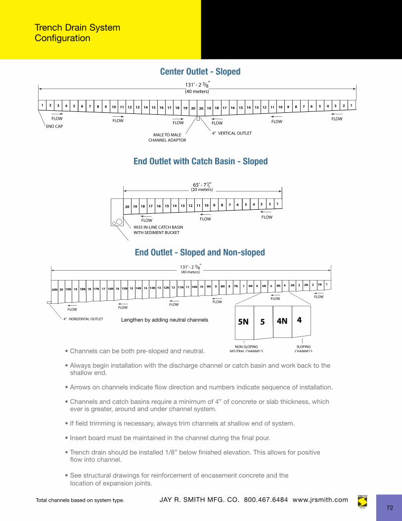
Trench Drain System Configuration
• Channels can be both pre-sloped and neutral.
• Always begin installation with the discharge channel or catch basin and work back to the shallow end.
• Arrows on channels indicate flow direction and numbers indicate sequence of installation.
• Channels and catch basins require a minimum of 4” of concrete or slab thickness, which ever is greater, around and under channel system.
• If field trimming is necessary, always trim channels at shallow end of system.
• Insert board must be maintained in the channel during the final pour.
• Trench drain should be installed 1/8” below finished elevation. This allows for positive flow into channel.
• See structural drawings for reinforcement of encasement concrete and the location of expansion joints.
JAY R. SMITH MFG. CO. 800.467.6484 www.jrsmith.com
End Outlet - Sloped and Non-sloped
Center Outlet - Sloped
End Outlet with Catch Basin - Sloped
Lengthen by adding neutral channels
Total channels based on system type.
72

SPM07470618
Innovative Spirit and Engineering Foundation
“What sets us apart from competitors is our engineering
and spirit. We have a ‘can-do’ spirit. If you ask us to do
something, we will do it or figure out how to do it. That’s
the part our customers like, that’s the part we like.”
- Don Morris, President and CEO
MORRIS GROUPINTERNATIONAL
brands built to last!
P.O. Box 3237 • Montgomery, AL 36109 TEL: 334.277.8520
www.jrsmith.com 2781 Gunter Park Dr. East • Montgomery, AL 36109-1405 United States(334) 277-8520 • www.jrsmith.com
Font used: BEBAS NEUE
MORRIS INTERNATIONAL ME FZE
Est. 1946
Est. 1989
Est. 1853
Est. 1937
Est. 2014
Est. 2013
Est. 2015
Est. 1945
Est. 1953
Est. 1945
Est. 1990
Est. 2008
Est. 2013Est. 2014
Est. 1989
Est. 2015
Est. 1995
Est. 1958
Est. 1972
Est. 1966
Est. 1926
Est. 1954
Est. 1984 Est. 1953
Est. 1998