YOKOSUKA Cruise Report YK12-14 system for … Cruise Report YK12-14 Evaluation of hybrid submersible...
19
YOKOSUKA Cruise Report YK12-14 Evaluation of hybrid submersible gravity observation system for exploration of seafloor hydrothermal deposits by using an underwater vehicle Sagami-bay Sep.6, 2012-Sep.10, 2012 Japan Agency for Marine-Earth Science and Technology (JAMSTEC)
Transcript of YOKOSUKA Cruise Report YK12-14 system for … Cruise Report YK12-14 Evaluation of hybrid submersible...

YOKOSUKA Cruise Report
YK12-14
Evaluation of hybrid submersible gravity observation
system for exploration of seafloor hydrothermal deposits
by using an underwater vehicle
Sagami-bay
Sep.6, 2012-Sep.10, 2012
Japan Agency for Marine-Earth Science and Technology
(JAMSTEC)

1
Notice on Using
This cruise report is a preliminary documentation as of the end of the cruise.
This report may not be corrected even if changes on contents (i.e. taxonomic classifications) may
be found after its publication. This report may also be changed without notice. Data on this cruise
report may be raw or unprocessed. If you are going to use or refer to the data written on this
report, please ask the Chief Scientist for latest information.
Users of data or results on this cruise report are requested to submit their results to the Data
Management Group of JAMSTEC.

2
Contents 1. Cruise Information 2. Researchers 3. Observation
- Background and objectives of the cruise
- Instruments and methods
Gravimeter system
Gravity gradiometer
- Research results and future plans
- References
- Cruise log
- URASHIMA operation team
- Ship crews
3
1. Cruise Information ● Cruise ID YK12-14
● Name of vessel YOKOSUKA and URASHIMA
● Title of the cruise Evaluation of hybrid submersible gravity observation system for exploration of
seafloor hydrothermal deposits by using an underwater vehicle
● Title of proposal Evaluation of hybrid submersible gravity observation system for exploration of
seafloor hydrothermal deposits by using an underwater vehicle
● Cruise period From September 6th, 2012 to September 10th, 2012
● Ports of call From Yokosuka (JAMSTEC) to Yokosuka (JAMSTEC)
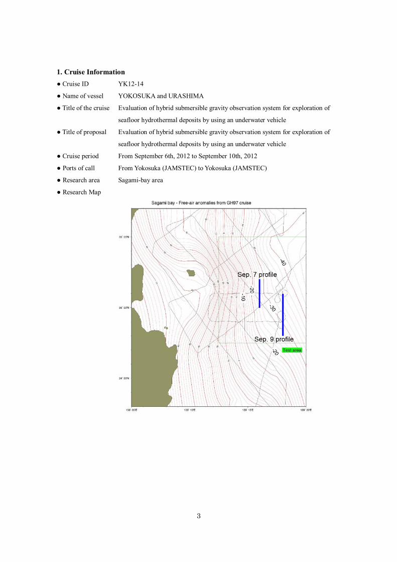
● Research area Sagami-bay area
● Research Map
4
2. Researchers ● Chief scientist [Affiliation]
Masanao SHINOHARA [Earthquake Research Institute, University of Tokyo]
● Representative of the science party [Affiliation]
Masanao SHINOHARA [Earthquake Research Institute, University of Tokyo]
● Science party (List) [Affiliation]
Masanao Shinohara [University of Tokyo]
Akito Araya [University of Tokyo]
Tomoaki Yamada [University of Tokyo]
Yagi Takeo [University of Tokyo]
Kenji Uehira [NIED]
Hiromi Fujimoto [IRIDeS, Tohoku University]
Shirasaki Yuichi [Marine Eco,Tech Ltd]
Toshiaki Sakurai [LINK LAB. inc.]
Shingo Kamoshida [LINK LAB. inc.]
Yasutaka Kakinuma [Q・I inc]
Yuuki Toyoshima [Q・I inc]
Takeshi Yoshiume [JAMSTEC]
Satoshi Tsukioka [JAMSTEC]
Shigeo Matsuda [Clovertech Inc]
Mamoru Sano [NME]
5
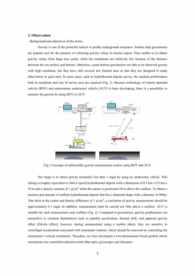
3. Observation - Background and objectives of the cruise,
Gravity is one of the powerful indices to profile underground structures. Surface ship gravimeters
are popular tool for the purpose of collecting gravity values in marine region. They enable us to obtain
gravity values from large area easily, while the resolutions are relatively low because of the distance
between the sea surface and bottom. Otherwise, ocean bottom gravimeters are able to be observed gravity
with high resolution, but they have still covered few limited sites so that they are designed to make
observation in quiet only. In some cases, such as hydrothermal deposit survey, the medium performance
both in resolution and size of survey area are required (Fig. 1). Because technology of remote operated
vehicle (ROV) and autonomous underwater vehicle (AUV) is been developing, there is a possibility to
measure the gravity by using ROV or AUV.
Fig.1 Concepts of submersible gravity measurement system using ROV and AUV.
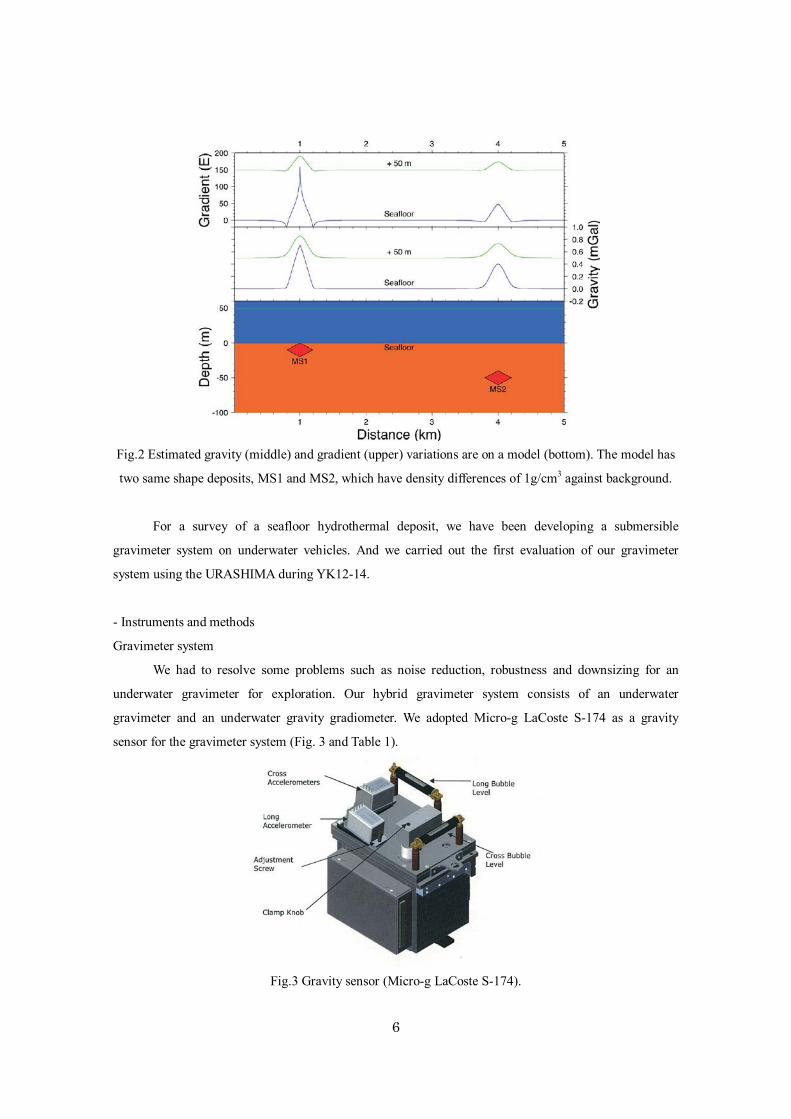
Our target is to detect gravity anomalies less than 1 mgal by using an underwater vehicle. This
setting is roughly equivalent to find a typical hydrothermal deposit with a dimension of 0.5 km x 0.5 km x
10 m and a density contrast of 1 g/cm3 when the sensor is positioned 50 m above the seafloor. To obtain a
position and amount of seafloor hydrothermal deposit that has a diamond shape with a diameter of 400m,
20m thick at the center and density difference of 1 g/cm3, a resolution of gravity measurement should be
approximately 0.1 mgal. In addition, measurement must be carried out 50m above a seafloor. AUV is
suitable for such measurement near seafloor (Fig. 2). Compared to gravimeters, gravity gradiometers are
insensitive to common disturbances such as parallel acceleration, thermal drift, and apparent gravity
effect (Eötvös effect); however, during measurement using a mobile object, they are sensitive to
centrifugal acceleration associated with instrument rotation, which should be removed by controlling the
instrument’s vertical orientation. Therefore, we have developed a two-dimensional forced gimbal whose
orientations are controlled referred to both fiber-optic gyroscopes and tiltmeters.
6
Fig.2 Estimated gravity (middle) and gradient (upper) variations are on a model (bottom). The model has
two same shape deposits, MS1 and MS2, which have density differences of 1g/cm3 against background.
For a survey of a seafloor hydrothermal deposit, we have been developing a submersible
gravimeter system on underwater vehicles. And we carried out the first evaluation of our gravimeter
system using the URASHIMA during YK12-14.
- Instruments and methods
Gravimeter system
We had to resolve some problems such as noise reduction, robustness and downsizing for an
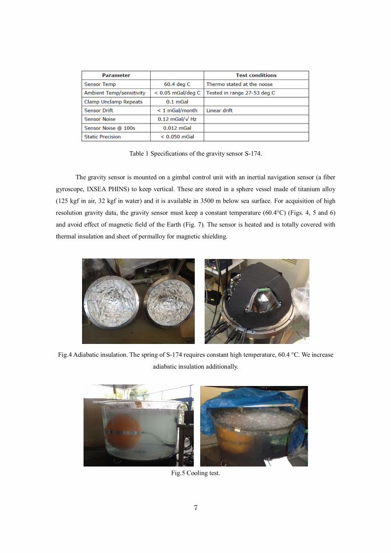
underwater gravimeter for exploration. Our hybrid gravimeter system consists of an underwater
gravimeter and an underwater gravity gradiometer. We adopted Micro-g LaCoste S-174 as a gravity
sensor for the gravimeter system (Fig. 3 and Table 1).
Fig.3 Gravity sensor (Micro-g LaCoste S-174).
7
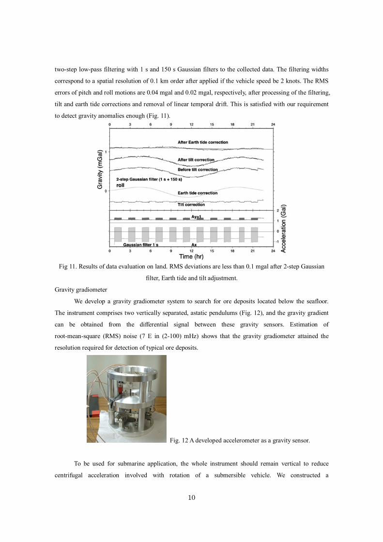
Table 1 Specifications of the gravity sensor S-174.
The gravity sensor is mounted on a gimbal control unit with an inertial navigation sensor (a fiber
gyroscope, IXSEA PHINS) to keep vertical. These are stored in a sphere vessel made of titanium alloy
(125 kgf in air, 32 kgf in water) and it is available in 3500 m below sea surface. For acquisition of high
resolution gravity data, the gravity sensor must keep a constant temperature (60.4°C) (Figs. 4, 5 and 6)
and avoid effect of magnetic field of the Earth (Fig. 7). The sensor is heated and is totally covered with
thermal insulation and sheet of permalloy for magnetic shielding.
Fig.4 Adiabatic insulation. The spring of S-174 requires constant high temperature, 60.4 °C. We increase
adiabatic insulation additionally.
Fig.5 Cooling test.

8
Fig.6 Results of the cooling test. We conformed that outside temperature does not affect the system.
Fig.7 The permaaloy case contains the gravity sensor and DC servo motors for the gimbal system.
Magnetic effects are reduced from 0.2 mgal to less than 0.001 mgal.
In order to reduce high frequency noise due to mainly the vehicle motion, the data are decimated
using low-pass filter and stored at sampling rates of approximately 100 Hz. The logging system and
control unit for communication to/from ship is stored another cylinder-shape canister (22 kgf in air, 10
kgf in water) (Figs. 8, 9 and 10).
Elapse time (hour)
Grav. Permalloy Air Capsule Water Air
Tem
pera
ture
(°C)
225°
0°
90°

9
Fig. 8 Systematic diagram of the gravimeter system.
Fig.9 Sensor unit of the gravimeter system and perspective.
Fig 10. Data acquisition unit.
We made gravity measurement experiments to examine the effectiveness of the gimbal system and
filtering application. The gravimeter was set on a machine simulating pitch and roll motions with a period
of 16 s and amplitude of 7.5 degrees, which is greater than expected in actual vehicle motions. We applied
Accelerometers
Back-up batteries
Data recording unit
10
two-step low-pass filtering with 1 s and 150 s Gaussian filters to the collected data. The filtering widths
correspond to a spatial resolution of 0.1 km order after applied if the vehicle speed be 2 knots. The RMS
errors of pitch and roll motions are 0.04 mgal and 0.02 mgal, respectively, after processing of the filtering,
tilt and earth tide corrections and removal of linear temporal drift. This is satisfied with our requirement
to detect gravity anomalies enough (Fig. 11).
Fig 11. Results of data evaluation on land. RMS deviations are less than 0.1 mgal after 2-step Gaussian
filter, Earth tide and tilt adjustment.
Gravity gradiometer
We develop a gravity gradiometer system to search for ore deposits located below the seafloor.
The instrument comprises two vertically separated, astatic pendulums (Fig. 12), and the gravity gradient
can be obtained from the differential signal between these gravity sensors. Estimation of
root-mean-square (RMS) noise (7 E in (2-100) mHz) shows that the gravity gradiometer attained the
resolution required for detection of typical ore deposits.
Fig. 12 A developed accelerometer as a gravity sensor.
To be used for submarine application, the whole instrument should remain vertical to reduce
centrifugal acceleration involved with rotation of a submersible vehicle. We constructed a
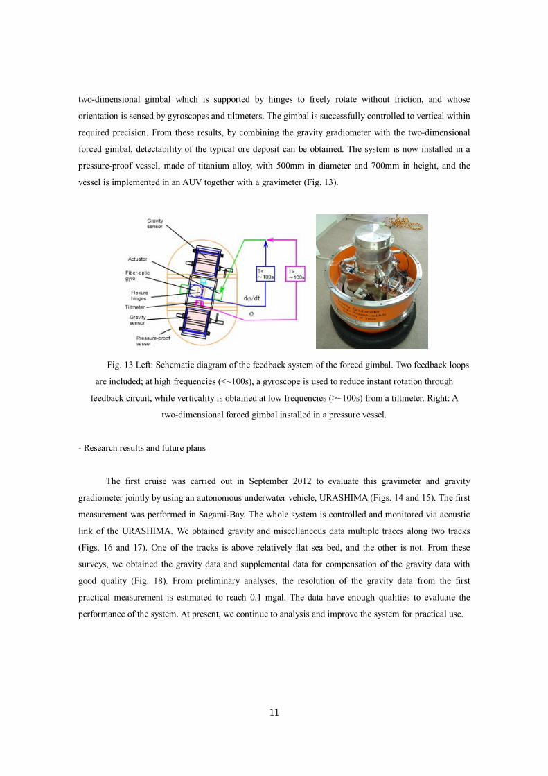
11
two-dimensional gimbal which is supported by hinges to freely rotate without friction, and whose
orientation is sensed by gyroscopes and tiltmeters. The gimbal is successfully controlled to vertical within
required precision. From these results, by combining the gravity gradiometer with the two-dimensional
forced gimbal, detectability of the typical ore deposit can be obtained. The system is now installed in a
pressure-proof vessel, made of titanium alloy, with 500mm in diameter and 700mm in height, and the
vessel is implemented in an AUV together with a gravimeter (Fig. 13).
Fig. 13 Left: Schematic diagram of the feedback system of the forced gimbal. Two feedback loops
are included; at high frequencies (<~100s), a gyroscope is used to reduce instant rotation through
feedback circuit, while verticality is obtained at low frequencies (>~100s) from a tiltmeter. Right: A
two-dimensional forced gimbal installed in a pressure vessel.
- Research results and future plans
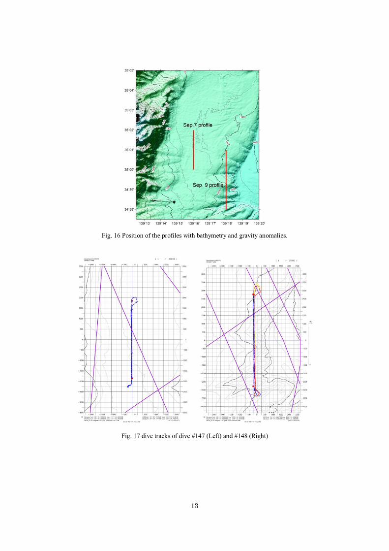
The first cruise was carried out in September 2012 to evaluate this gravimeter and gravity
gradiometer jointly by using an autonomous underwater vehicle, URASHIMA (Figs. 14 and 15). The first
measurement was performed in Sagami-Bay. The whole system is controlled and monitored via acoustic
link of the URASHIMA. We obtained gravity and miscellaneous data multiple traces along two tracks
(Figs. 16 and 17). One of the tracks is above relatively flat sea bed, and the other is not. From these
surveys, we obtained the gravity data and supplemental data for compensation of the gravity data with
good quality (Fig. 18). From preliminary analyses, the resolution of the gravity data from the first
practical measurement is estimated to reach 0.1 mgal. The data have enough qualities to evaluate the
performance of the system. At present, we continue to analysis and improve the system for practical use.

12
Fig. 14 Schematic of YK12-14 cruise measurement
Fig.15 Layout of the system on the URASHIMA
13
Fig. 16 Position of the profiles with bathymetry and gravity anomalies.
Fig. 17 dive tracks of dive #147 (Left) and #148 (Right)

14
Fig 18. Gravity and miscellaneous data obtained during the dive.
15
- References
Araya, A., T. Kanazawa, M. Shinohara, T. Yamada, H. Fujimoto, K. Iizasa, and T. Ishihara, Gravity
gradiometer implemented in AUV for detection of seafloor massive sulfides, OCEANS 2012
IEEE Hampton Roads Conference & Exhibition, Virginia Beach, U.S.A., 16-18 October, 2012,
IEEE Catalog Number CFP120OCE-DVD, 120601-087, 2012.
Araya, A., T. Kanazawa, M. Shinohara, T. Yamada, H. Fujimoto, K. Iizasa, and T. Ishihara, A gravity
gradiometer to search for submarine ore deposits, Symposium on Underwater Technology 2011
& Workshop on Scientific Use of Submarine Cables and Related Technologies 2011, Tokyo,
Japan, 5-8 April, 2011, IEEE, 1064, 2011.
Araya, A., K. Sekiya, and Y. Shindo, Laser-interferometric broadband seismometer for ocean borehole
observations, International Symposium on Underwater Technology 2007, Tokyo, Japan, 17-20
April, 2007, IEEE, 245-248, 2007.
Fujimoto, H., T. Kanazawa, M. Shinohara, A. Araya, T. Yamada, K. Mochizuki, T. Ishihara, and K. Iizasa,
Development of a hybrid gravimeter system onboard an underwater vehicle, Symposium on
Underwater Technology 2011 & Workshop on Scientific Use of Submarine Cables and Related
Technologies 2011, Tokyo, Japan, 5-8 April, 2011, IEEE, 1111, 2011.
Fujimoto, H., K. Nozaki, Y. Kawano, N. Demboya, A. Oshida, K. Koizumi, S. Mitsuishi, K. Iwamoto,
and T. Kanazawa, Remodeling of an ocean bottom gravimeter and littoral seafloor gravimetry -
toward the seamless gravimetry on land and seafloor -, J. Geod. Soc. Japan, vol. 55, pp.325-339,
2009.
Fujimoto, H., K. Koizumi, M. Watanabe, A. Oshida, T. Furuta, N. Takamura, and T. Ura, Underwater
gravimeter on board the R-One Robot, Proc. UT2000, IEEE Catalog No. 00EX418, pp.297-300,
2000.
Kanazawa, T., H. Fujimoto, M. Shinohara, A. Araya, T. Yamada, K. Iizasa, and T. Ishihara, New
underwater hybrid gravity measurement system consisting of a gravimeter and a gradiometer,
Proc. 22nd Ocean Engineering Symposium, Tokyo, March 17-18, 2011, OES22-043.
Yamada, T., Kanazawa, T., Fujimoto, H., Shinohara, M., Ishihara, T., Araya, A., Iizasa, K., Tsukioka, S.,
Development of a submersible gravimeter on underwater vehicles, 2012 AGU Fall Meeting,
OS51D-1902, 2012
16
- Cruise log
2012/09/06
Weather: Blue sky/ Wind direction: SSW/ Wind scale: 3 (Gentle breeze)/ Wave scale: 1 (Smooth)/ Swell
scale: 0 (No swell)/ Visibility: 8 miles
12:30 Onboard
13:00 Let go all shore lines. Left YOKOSUKA for research area (Sagami Bay).
14:30 - 15:00 Carried out shipboard education & training for scientists.
15:30 - 16:10 Scientific meeting And General Briefing about URASHIMA.
15:50 Arrived at research area.
15:53 - 16:11 Carried out eight figure running.
16:14 Released XBT at <35-01.3438N, 139-18.7531E>.
16:40 - 17:00 Praying for the safety of this cruise (Konpira ceremony).
2012/09/07
Weather: Fine but Cloudy/ Wind direction: NNE/ Wind scale: 2 (Light breeze)/ Wave scale: 2 (Smooth)/
Swell scale: 1 (Low swell)/ Visibility: 6 miles
07:31 Launched URASHIMA.
07:32 URASHIMA dove and started operation #147.
12:53 URASHIMA refloated.
13:09 Hoisted up URASHIMA.
13:18 Recovered URASHIMA and finished operation.
17:30 - 18:00 Scientific meeting And General Briefing about URASHIMA.
2012/09/08
Weather: Fine but Cloudy/ Wind direction: ---/ Wind scale: 0 (Calm)/ Wave scale: 1 (Calm)/ Swell scale:
1 (Low swell)/ Visibility: 8 miles
07:18 Hoisted up URASHIMA.
07:33 Recovered URASHIMA.
08:20 Suspended URASHIMA operation due to mechanical trouble.
2012/09/09
Weather: Fine but Cloudy/ Wind direction: SE/ Wind scale: 3 (Gentle breeze)/ Wave scale: 2 (Smooth)/
Swell scale: 1 (Low swell)/ Visibility: 8 miles
07:14 Launched URASHIMA.
07:15 URASHIMA dove and started operation #148.
17
16:15 URASHIMA refloated.
16:35 Hoisted up URASHIMA.
16:43 Recovered URASHIMA and finished operation.
17:00 Left the survey area for Tateyama.
19:09 Arrived at Tateyama.
2012/09/10
Weather: Fine but cloudy/ Wind direction: South/ Wind scale: 4 (Moderate breeze)/ Wave scale: 3
(Slight)/ Swell scale: 1 (Low swell, short)/ Visibility: 8miles
05:30 Finished MNBES mapping survey. Left survey area for YOKOSUKA.
Time of Arrived was 9:30, 2012/09/24
- URASHIMA operation team
Operation Manager Satoshi Ogura
1st Submersible Staff Shinobu Omika
1st Submersible Staff Masanobu Yanagitani
2nd Submersible Staff Keigo Suzuki
2nd Submersible Staff Akihisa Ishikawa
2nd Submersible Staff Takuma Onishi
- Ship crews
Captain Ukekura Eiko
Chief Officer Yasuhiko Sammori
2nd Officer Shozo Fujii
3rd Officer Hiroharu Omae
Chief Engineer Eiji Sakaguchi
1st Engineer Kimio Matsukawa
2nd Engineer Daisuke Gibu
3rd Engineer Kota Kataoka
Chief Electronic Operator Takehito Hattori
2nd Electronic Operator Yosuke Komaki
3rd Electronic Operator Ryousuke Komatsu
Boat Swain Masanori Ohata
Able Seaman Kazumi Ogasawara
Able Seaman Yuki Yoshino
Able Seaman Takuya Miyashita
18
Sailor Shinsuke Uzuki
Sailor Toru Nakanishi
No.1 Oiler Kozo Miura
Oiler Katsuyuki Miyazaki
Oiler Yoshinori Kawai
Assistant Oiler Eiji Aratake
Assistant Oiler Toru Hidaka
Assistant Oiler Naoto Mituo
Chief Steward Sueto Sasaki
Steward Shigeto Ariyama
Steward Yoshinobu Hasatani
Steward Tatsunari Onoue
Steward Toru Wada