Year 7 Phase 3 - Ark Globe Academy 7 Science Work Pack Pha… · 2. Check for understanding and...
57
Year 7 Phase 3 SCIENCE WORKBOOK Name: ___________________________________________________
Transcript of Year 7 Phase 3 - Ark Globe Academy 7 Science Work Pack Pha… · 2. Check for understanding and...
1
Year 7 Phase 3 SCIENCE WORKBOOK
Name: ___________________________________________________
2
Session Title Work to be completed
Resource provided
Outcome On-Line Support
1 Static Electricity and Atomic structure
DO NOW Apply tasks
Phase III Workbook with tasks Pages 4-7
Completed: 1.DO NOW 2. Check for understanding and apply tasks
Session 1 + 2 Static electricity and atomic structure lesson on VLE
2 Static Electricity and Atomic structure
Do Now Apply tasks
Phase III Workbook with tasks Pages 8-10
Completed: 1.DO NOW 2. Apply tasks
See above
3 Circuits DO NOW Apply tasks
Phase III Workbook with tasks Pages 11-14
Completed: 1.DO NOW 2. Check for understanding and apply tasks
Session 3 + 4 Circuits lesson on VLE
4 Circuits Do Now Apply tasks
Phase III Workbook with tasks Pages 15- 23
Completed: 1.DO NOW 2. Apply tasks
See above
5 Current DO NOW Check for Understanding Task
Phase III Workbook with tasks Pages 24-26
Completed: 1.DO NOW 2.Check for Understanding Task
Session 5 + 6 Current lesson on VLE
6 Current Apply Tasks
Phase III Workbook with tasks Page 27-30
Completed: 1.Apply task
See above
7 Potential Difference
DO NOW Apply tasks
Phase III Workbook with tasks Pages 31-36
Completed: 1.DO NOW 2. Apply tasks
Session 7 Potential Difference 1 on VLE
8 Potential Difference
DO NOW Apply tasks
Phase III Workbook with tasks
Completed: 1.DO NOW
Session 8 Potential Difference 2 on VLE

3
Pages 37-39
2. Apply tasks
9 Series and parallel
DO NOW Check for Understanding Task
Phase III Workbook with tasks Pages 40-42
Completed: 1.DO NOW 2.Check for Understanding Task
Session 9 + 10 Series and parallel lesson on VLE
10 Series and parallel
Apply Tasks
Phase III Workbook with tasks Pages 43-47
Completed: 1.Apply task
See above
Exam question answers
Pages 48-57
4
Session 1
Static Electricity and Atomic Structure
Do Now:
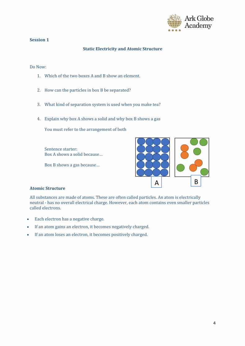
1. Which of the two boxes A and B show an element.
2. How can the particles in box B be separated?
3. What kind of separation system is used when you make tea?
4. Explain why box A shows a solid and why box B shows a gas You must refer to the arrangement of both
Sentence starter: Box A shows a solid because… Box B shows a gas because…
Atomic Structure
All substances are made of atoms. These are often called particles. An atom is electrically neutral - has no overall electrical charge. However, each atom contains even smaller particles called electrons.
• Each electron has a negative charge.
• If an atom gains an electron, it becomes negatively charged.
• If an atom loses an electron, it becomes positively charged.
A B
5
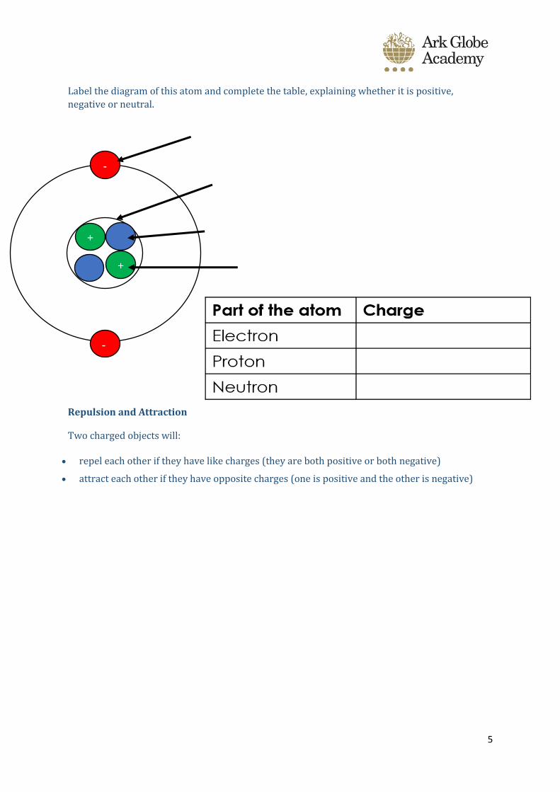
Label the diagram of this atom and complete the table, explaining whether it is positive,
negative or neutral.
Repulsion and Attraction
Two charged objects will:
• repel each other if they have like charges (they are both positive or both negative)
• attract each other if they have opposite charges (one is positive and the other is negative)
-
-
-
+
+
6
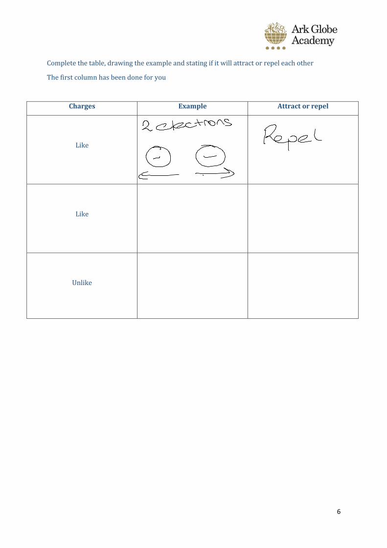
Complete the table, drawing the example and stating if it will attract or repel each other
The first column has been done for you
Charges Example Attract or repel
Like
Like
Unlike
7
8
Session 2
Do Now:
Correct the following statements
1. Electrons are found in the nucleus
2. Protons are negative
3. Neutrons are found in shells
4. Like charges attract
Electrons can move from one substance to another when objects are rubbed together. You may have done this with a party balloon: if you rub a balloon on your sweater, you can get the balloon to stick to the wall or to your hair. This is because of static electricity.
Moving charges
When you rub two different materials against each other, they become electrically charged. This only works for electrically insulated objects and not with materials like metals, which conduct.
Transferring electrons to an object gives it a negative charge
Jumper and balloon example
Electrons transfer from the jumper to the balloon so…
- the balloon is negatively charged up
- The jumper is positively charged up
Q1 What happens when you charge up plastic and place it near a stream of water?
(Watch youtube video in the powerpoint to help you with this question)
Keywords you must use:
Negatively charged
Electrons
Protons
9
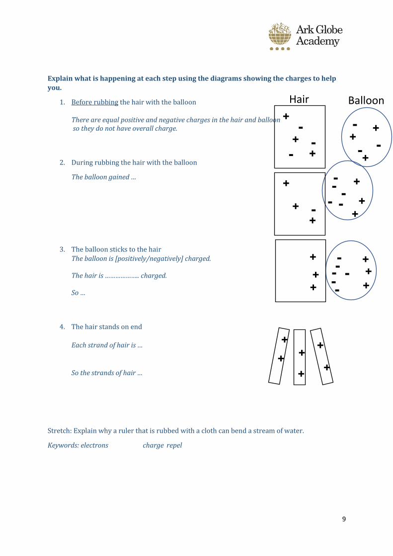
Explain what is happening at each step using the diagrams showing the charges to help
you.
1. Before rubbing the hair with the balloon
There are equal positive and negative charges in the hair and balloon so they do not have overall charge.
2. During rubbing the hair with the balloon
The balloon gained …
3. The balloon sticks to the hair
The balloon is [positively/negatively] charged. The hair is ……………….. charged. So …
4. The hair stands on end
Each strand of hair is …
So the strands of hair …
Stretch: Explain why a ruler that is rubbed with a cloth can bend a stream of water.
Keywords: electrons charge repel
- -
- -
+
+ +
-
- +
+
+
Hair Balloon
- -
-
-
+
+
+ - -
+
+
+
- -
-
-
+
+
+
- - +
+
+
+
+
+
+ +
+
10
Correct the following statements
1. Friction causes protons to be transferred
2. When electrons are transferred, it makes an object positively charged
3. A positive and a negative charge repel
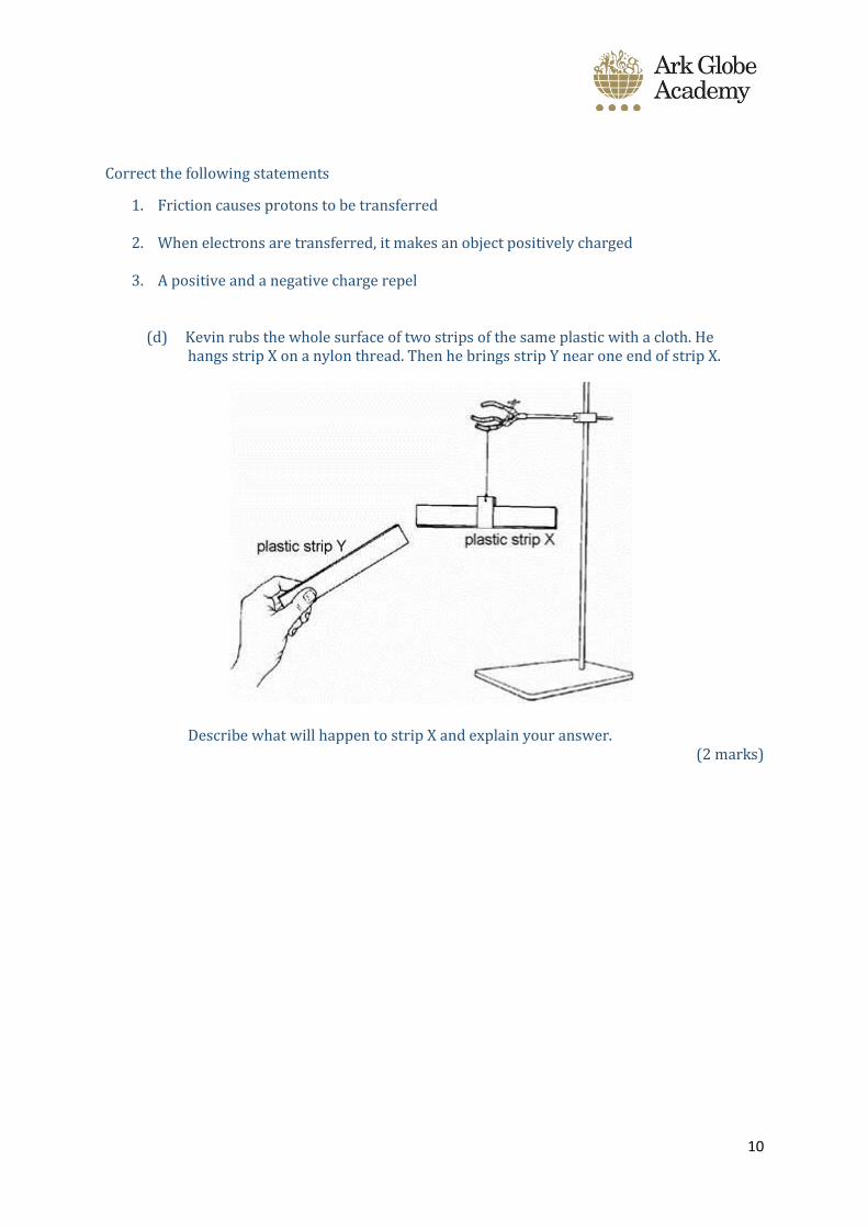
(d) Kevin rubs the whole surface of two strips of the same plastic with a cloth. He hangs strip X on a nylon thread. Then he brings strip Y near one end of strip X.
Describe what will happen to strip X and explain your answer. (2 marks)
11
Session 3
Circuits
Do Now:
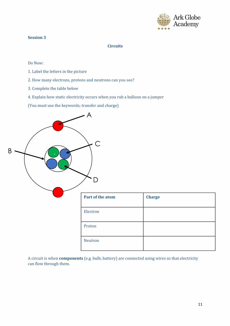
1. Label the letters in the picture
2. How many electrons, protons and neutrons can you see?
3. Complete the table below
4. Explain how static electricity occurs when you rub a balloon on a jumper
(You must use the keywords; transfer and charge)
A circuit is when components (e.g. bulb, battery) are connected using wires so that electricity
can flow through them.
Part of the atom Charge
Electron
Proton
Neutron
-
-
+
+
A
D
C
B
12
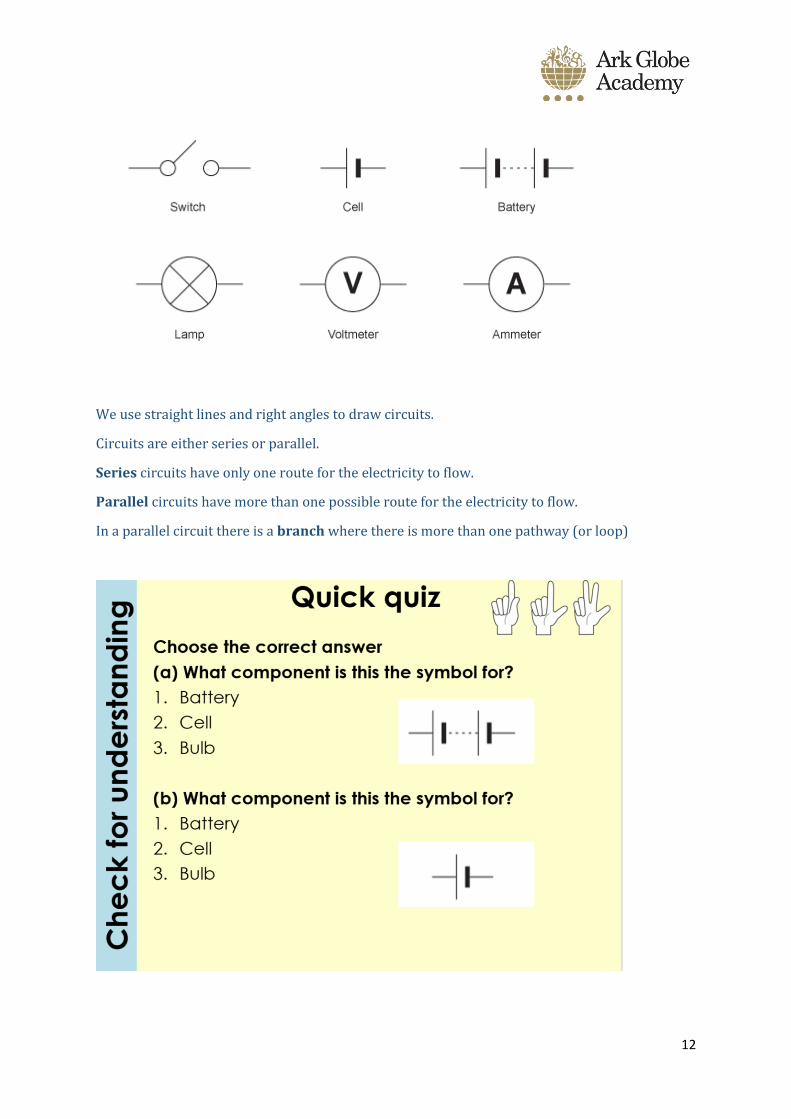
We use straight lines and right angles to draw circuits.
Circuits are either series or parallel.
Series circuits have only one route for the electricity to flow.
Parallel circuits have more than one possible route for the electricity to flow.
In a parallel circuit there is a branch where there is more than one pathway (or loop)
13
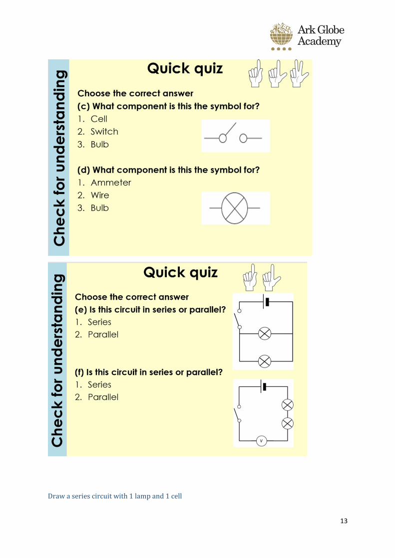
Draw a series circuit with 1 lamp and 1 cell
14
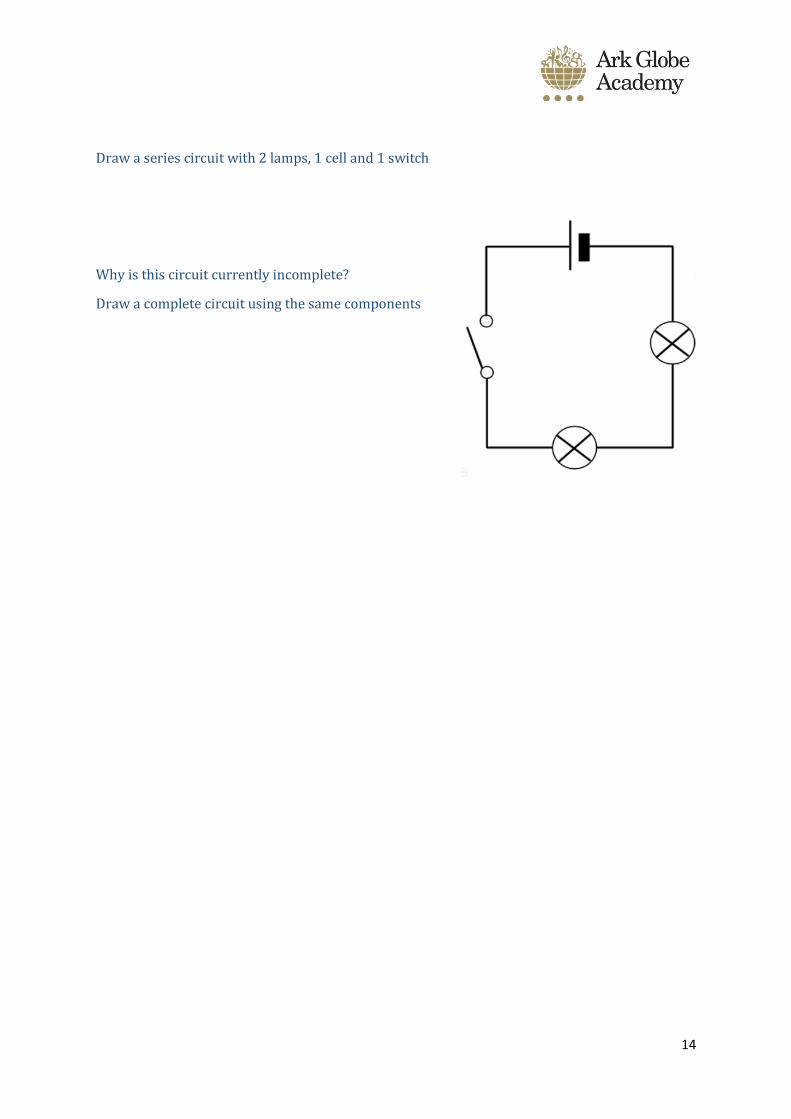
Draw a series circuit with 2 lamps, 1 cell and 1 switch
Why is this circuit currently incomplete?
Draw a complete circuit using the same components
15
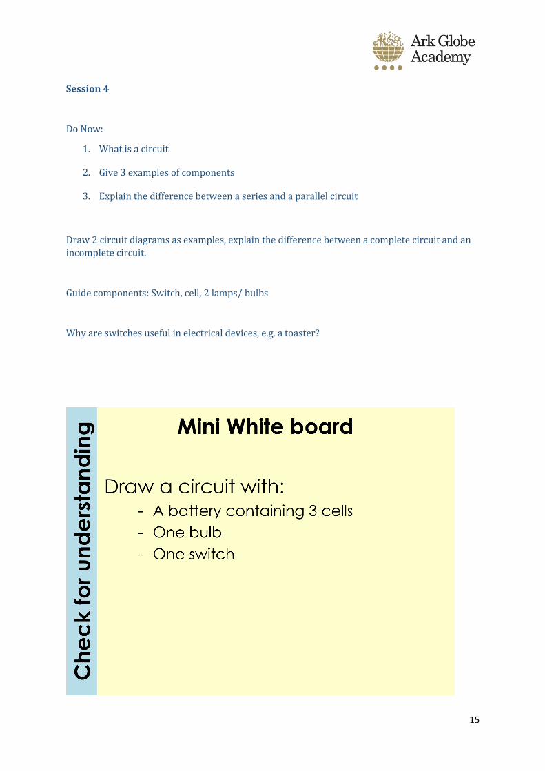
Session 4
Do Now:
1. What is a circuit
2. Give 3 examples of components
3. Explain the difference between a series and a parallel circuit
Draw 2 circuit diagrams as examples, explain the difference between a complete circuit and an
incomplete circuit.
Guide components: Switch, cell, 2 lamps/ bulbs
Why are switches useful in electrical devices, e.g. a toaster?

16
Complete the exam questions on circuits
Answers are on the student VLE in the document,
‘Circuits exam question mark scheme’
17
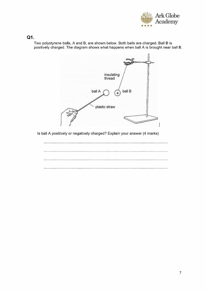
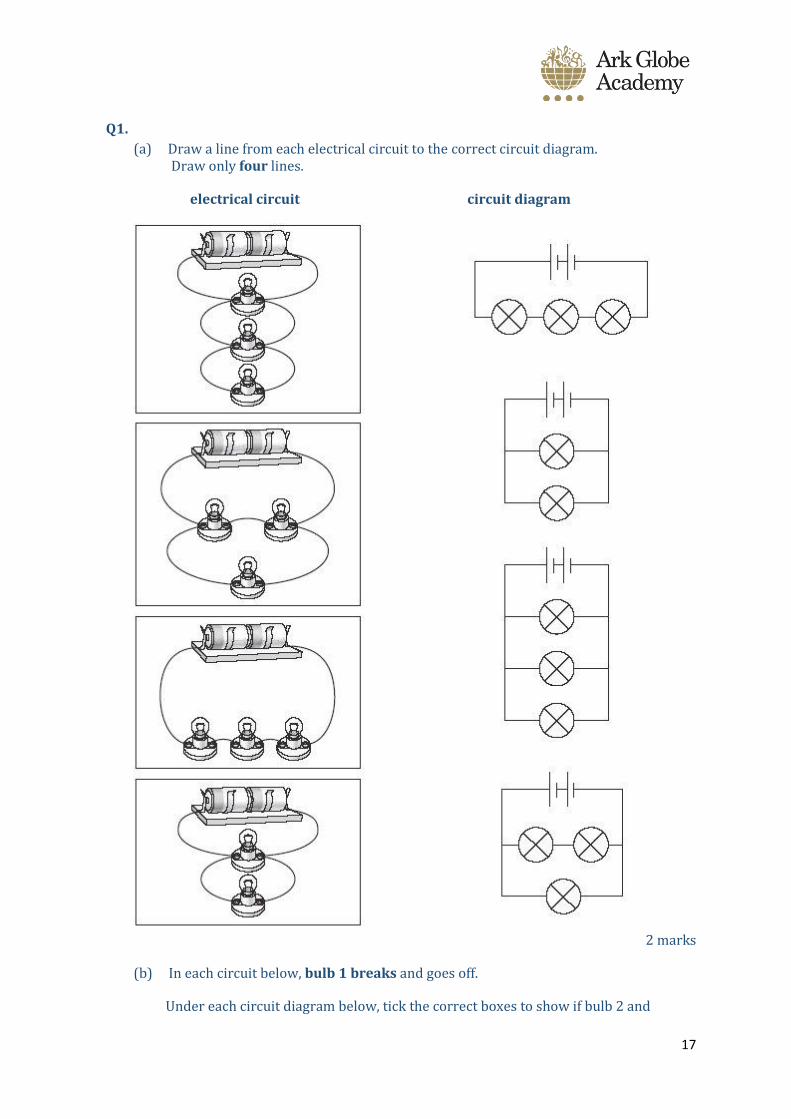
Q1.
(a) Draw a line from each electrical circuit to the correct circuit diagram. Draw only four lines.
electrical circuit circuit diagram
2 marks
(b) In each circuit below, bulb 1 breaks and goes off.
Under each circuit diagram below, tick the correct boxes to show if bulb 2 and

18
bulb 3 are on or off.
circuit A circuit B
2 marks
(c) Give the name of the part that provides energy for each circuit.
........................................................ 1 mark
(d) Why is copper used for wires in a circuit? Tick the correct box.
1 mark
maximum 6 marks
19
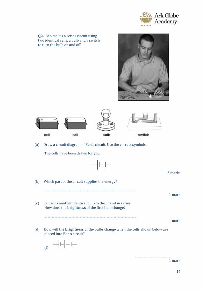
Q2. Ben makes a series circuit using two identical cells, a bulb and a switch to turn the bulb on and off.
(a) Draw a circuit diagram of Ben’s circuit. Use the correct symbols.
The cells have been drawn for you.
3 marks
(b) Which part of the circuit supplies the energy?
...................................................................................................................... 1 mark
(c) Ben adds another identical bulb to the circuit in series. How does the brightness of the first bulb change?
...................................................................................................................... 1 mark
(d) How will the brightness of the bulbs change when the cells shown below are placed into Ben’s circuit?
(i)
............................................. 1 mark
20
(ii)
............................................. 1 mark
maximum 7 marks
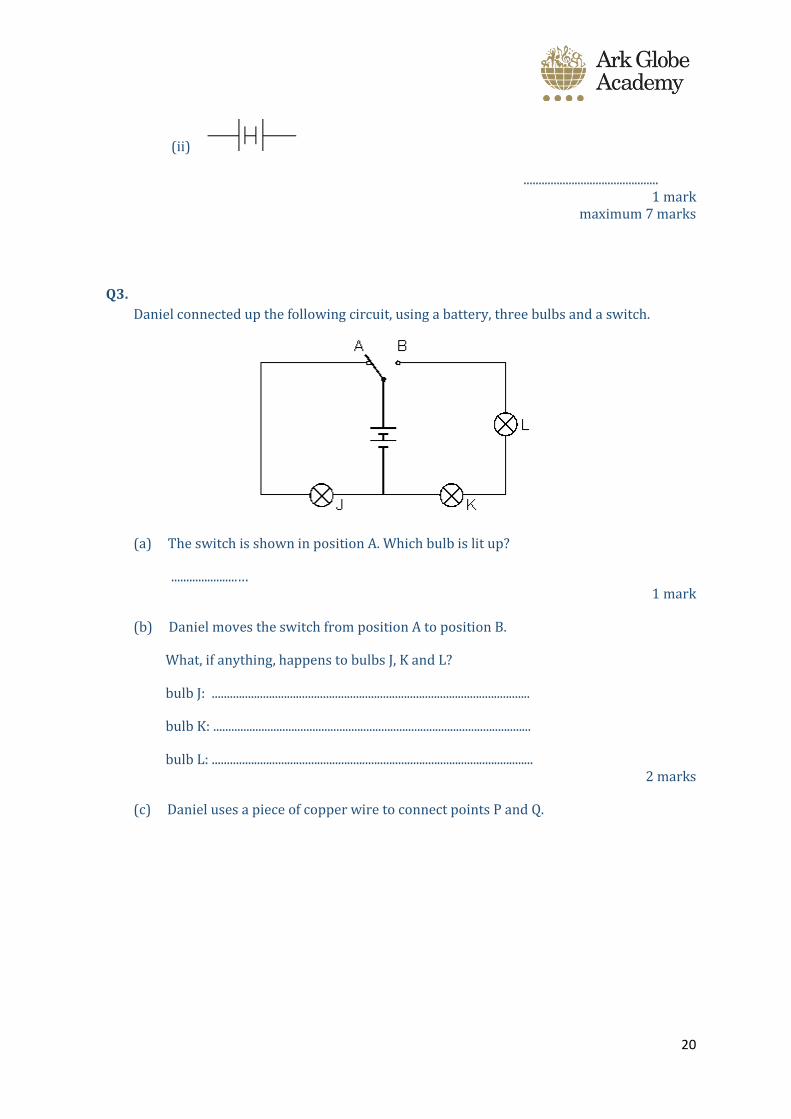
Q3.
Daniel connected up the following circuit, using a battery, three bulbs and a switch.
(a) The switch is shown in position A. Which bulb is lit up?
......................… 1 mark
(b) Daniel moves the switch from position A to position B.
What, if anything, happens to bulbs J, K and L?
bulb J: ..........................................................................................................
bulb K: ..........................................................................................................
bulb L: ........................................................................................................... 2 marks
(c) Daniel uses a piece of copper wire to connect points P and Q.
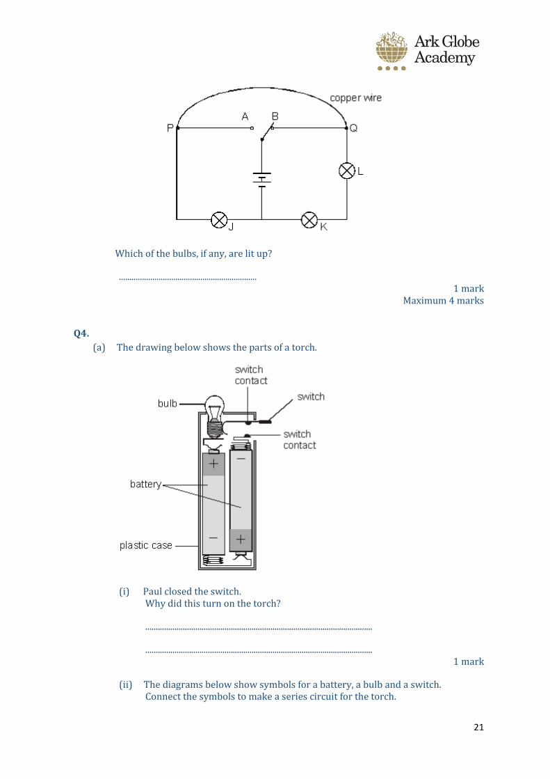
21
Which of the bulbs, if any, are lit up?
.................................................................. 1 mark
Maximum 4 marks
Q4.
(a) The drawing below shows the parts of a torch.
(i) Paul closed the switch. Why did this turn on the torch?
.............................................................................................................
............................................................................................................. 1 mark
(ii) The diagrams below show symbols for a battery, a bulb and a switch. Connect the symbols to make a series circuit for the torch.
22
1 mark
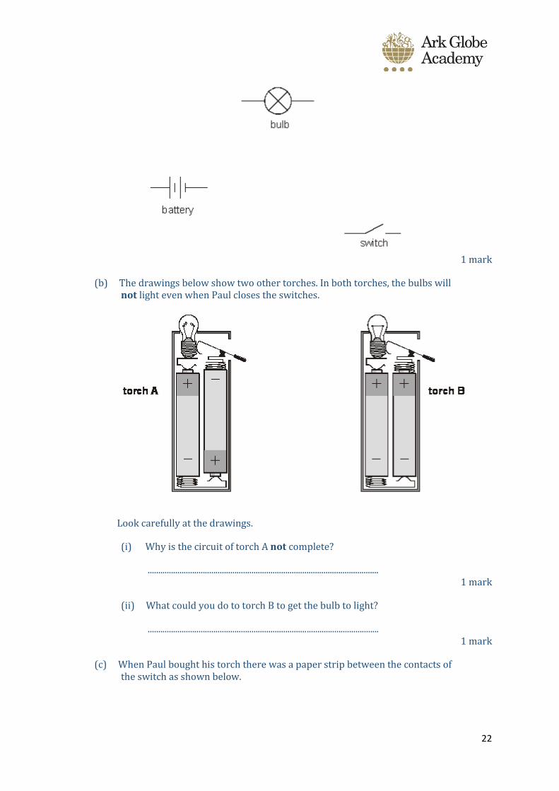
(b) The drawings below show two other torches. In both torches, the bulbs will not light even when Paul closes the switches.
Look carefully at the drawings.
(i) Why is the circuit of torch A not complete?
............................................................................................................. 1 mark
(ii) What could you do to torch B to get the bulb to light?
............................................................................................................. 1 mark
(c) When Paul bought his torch there was a paper strip between the contacts of the switch as shown below.
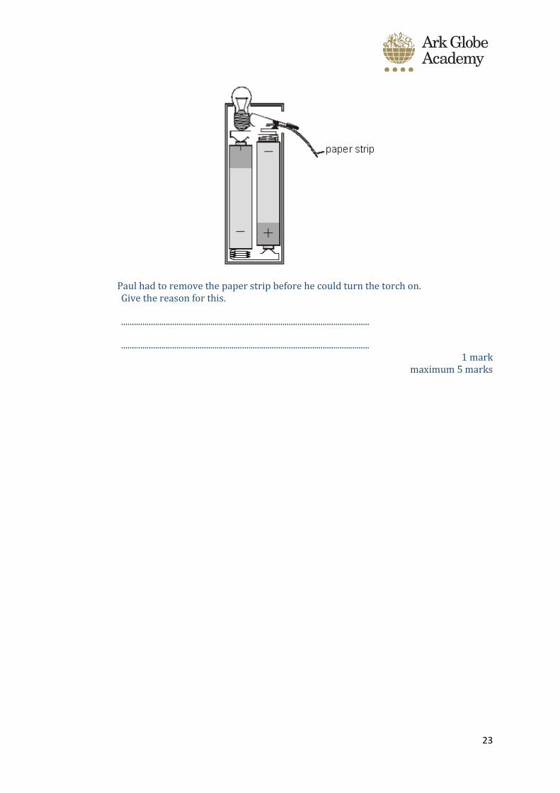
23
Paul had to remove the paper strip before he could turn the torch on. Give the reason for this.
.....................................................................................................................
..................................................................................................................... 1 mark
maximum 5 marks
24
Session 5
Do Now –
1. Draw a bulb symbol
2. Draw a battery symbol
3. What component can stop current flowing around a circuit
Stretch: Explain the difference between a series and a parallel circuit, using circuit
diagrams to support your points
Check answers by looking at the powerpoint/video, make notes from the
powerpoint/video and you can use the information below as well. All answers are found
on powerpoint/video
Some particles carry an electric charge (like protons and electrons). When it comes to wires,
these particles are electrons. We get an electric current when these electrons move from place
to place. Current is just a flow of charge, and in wires, this is a flow of electrons. These
electrons come from a battery/cell/power pack and for a current to flow you need a complete
path for the electrons to pass through (also known as an electric circuit).
KEY POINT: Current is a measure of how much electric charge flows through a circuit.
The more charge that flows, the bigger the current.
Current is measured in amperes. The symbol for ampere is A. For example, 20 A is a bigger
current than 5 A. The word ‘ampere’ is often abbreviated to ‘amp’, so people talk about how
many amps flow.
A device called an ammeter is used to measure current. Some types of ammeter have a pointer
on a dial, but most have a digital display. To measure the current flowing through a component
in a circuit, you must connect the ammeter in series with it.
25
Complete check for understanding – Remember, answers are on video/powerpoint.
Choose the correct answer
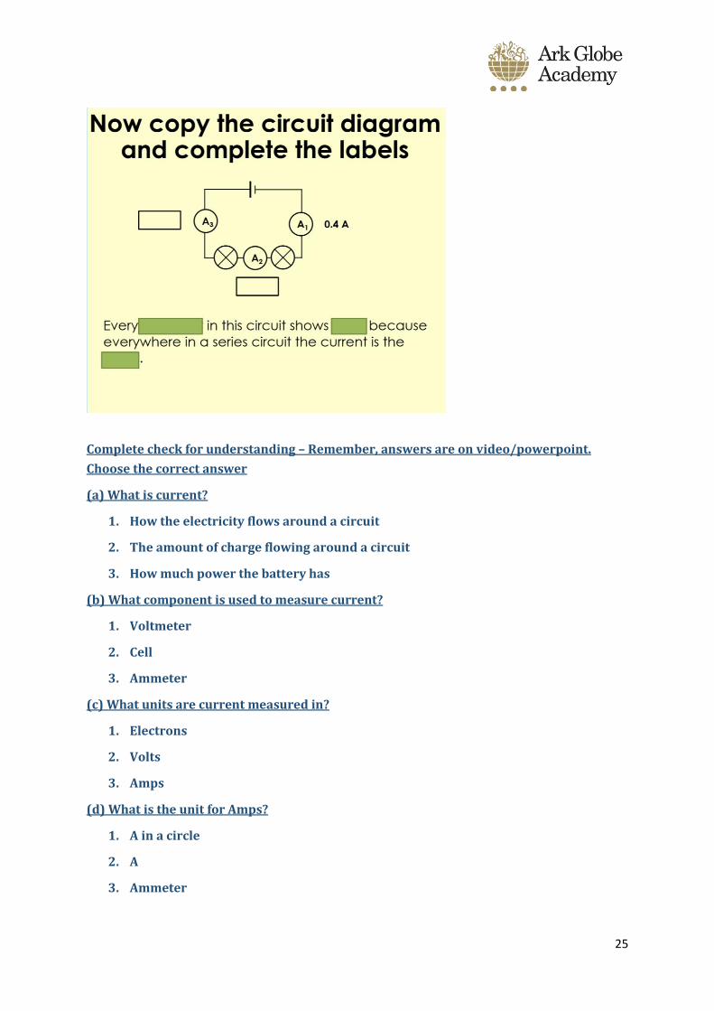
(a) What is current?
1. How the electricity flows around a circuit
2. The amount of charge flowing around a circuit
3. How much power the battery has
(b) What component is used to measure current?
1. Voltmeter
2. Cell
3. Ammeter
(c) What units are current measured in?
1. Electrons
2. Volts
3. Amps
(d) What is the unit for Amps?
1. A in a circle
2. A
3. Ammeter
26
27
Session 6
Do Now
Check answers by looking at ppt/video
Make notes based on powerpoint and below information
You can measure how current changes and the brightness of the bulb changes when more
bulbs are added to a series circuit. The more bulbs that are added to a circuit, the lower
the current will be. The more bulbs that are added to a circuit, each bulb will have a
lower brightness.
The current is the same everywhere in a series circuit. It does not matter where you put the
ammeter, it will give you the same reading.
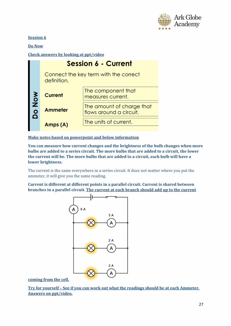
Current is different at different points in a parallel circuit. Current is shared between
branches in a parallel circuit. The current at each branch should add up to the current
coming from the cell.
Try for yourself – See if you can work out what the readings should be at each Ammeter.
Answers on ppt/video.

28
Complete the apply tasks below. Mark using the powerpoint/video.
Extension – Write a method for an investigation to find out the current at different
positions in the same circuit.
Apply tasks -
Q1.
1. What is the name of the equipment used to measure current and what are the units of current?
2. What is the difference between a series and a parallel circuit.
3. How would current change if more bulbs are added to the circuit?
4. How would brightness change if more bulbs are added to the circuit?
5. Suggest how you can increase the brightness of a bulb in a series circuit. 5 marks
Q2.
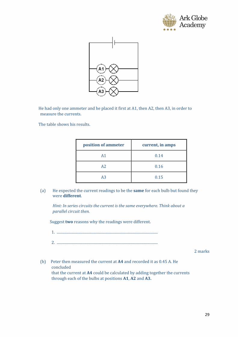
Peter measured the current through each of three similar bulbs in a parallel circuit.
29
He had only one ammeter and he placed it first at A1, then A2, then A3, in order to
measure the currents.
The table shows his results.
position of ammeter current, in amps
A1 0.14
A2 0.16
A3 0.15
(a) He expected the current readings to be the same for each bulb but found they were different.
Hint: In series circuits the current is the same everywhere. Think about a
parallel circuit then.
Suggest two reasons why the readings were different.
1. ................................................................................................................
2. ................................................................................................................
2 marks
(b) Peter then measured the current at A4 and recorded it as 0.45 A. He
concluded
that the current at A4 could be calculated by adding together the currents
through each of the bulbs at positions A1, A2 and A3.
30
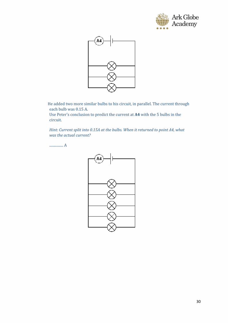
He added two more similar bulbs to his circuit, in parallel. The current through
each bulb was 0.15 A.
Use Peter's conclusion to predict the current at A4 with the 5 bulbs in the
circuit.
Hint: Current split into 0.15A at the bulbs. When it returned to point A4, what
was the actual current?
................ A
31
Session 7
Potential Difference 1
Do Now:
1. 1. If a circuit has no cell, what’s the problem?
2. Draw the symbol for an ammeter
3. Draw a circuit with a cell, lamp and ammeter
What is potential difference (pd)?
Another word for potential difference is voltage/volts/V (named after Italian physicist
Alessandra Volta, who invented the first electric battery).
PD is the force at which electricity moves through a conductor, such a metal wire. The greater
this force, the greater the PD. For example, an AA battery exerts a PD of 1.5 volts while your wall
socket exerts 240 volts. The AA battery will not harm you, but the socket will because more
energy is being transferred into you. If I added batteries together, I can increase the voltage. So
if one AA battery has 1.5V, two AA batteries have 3V. Voltage adds up.
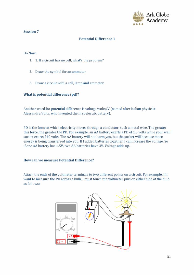
How can we measure Potential Difference?
Attach the ends of the voltmeter terminals to two different points on a circuit. For example, If I
want to measure the PD across a bulb, I must touch the voltmeter pins on either side of the bulb
as follows:
32
Q1.
(a) Draw a diagram to show how 1.5 V cells should be connected together to give
a potential difference of 4.5 V.
Use the correct circuit symbol for a cell.
(2)
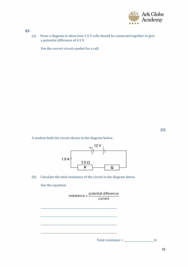
A student built the circuit shown in the diagram below.
(b) Calculate the total resistance of the circuit in the diagram above.
Use the equation:
___________________________________________________________
___________________________________________________________
___________________________________________________________
___________________________________________________________
Total resistance = _______________________ Ω

33
(2)
(c) The resistance of P is 3.5 Ω.
Calculate the resistance of Q.
___________________________________________________________
___________________________________________________________
___________________________________________________________
___________________________________________________________
Resistance of Q = ______________________ Ω
(1)
(d) The student connects the two resistors in the diagram above in parallel.
What happens to the total resistance of the circuit?
Tick one box.
It decreases
It increases
It does not change
(1)
Give a reason for your answer.
___________________________________________________________
___________________________________________________________
___________________________________________________________
___________________________________________________________
(1)
(Total 7 marks)

34
Q2.
Complete each of the following sentences, A, B, C, D and E, by choosing the correct
ending from K, L, M, N or O.
The first one has been done for you.
A The current through a resistor depends ______________________________
B A direct current _________________________________________________
C In a series circuit, the potential difference ____________________________
D An alternating current ____________________________________________
E In a parallel circuit, the potential difference ___________________________
K _____________________________________ across each component is the same.
L __________________________________________ is supplied by a cell or battery.
M _________________________________________ is constantly changing direction.
N ___________________________ of the power supply is shared by the components.
O ______________________________ on the potential difference across the resistor.
(Total 3 marks)
Q3.
(a) The lamps in the circuits drawn below are all identical.
Each of the cells has a potential difference of 1.5 volts.
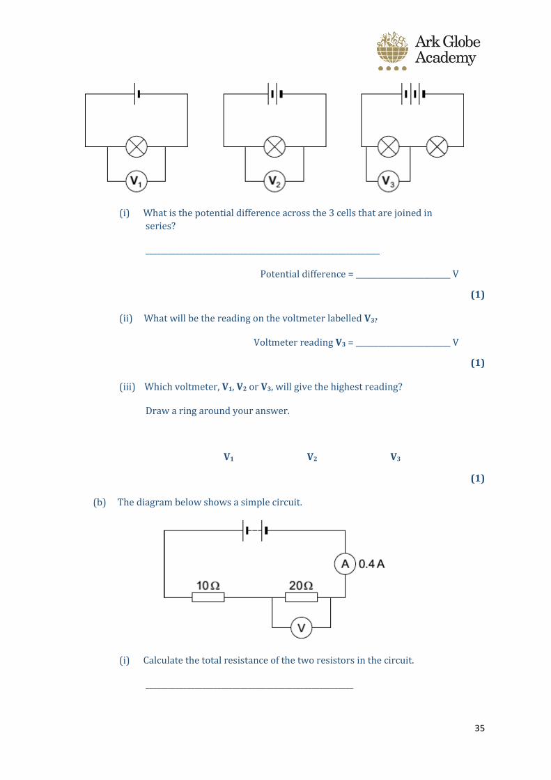
35
(i) What is the potential difference across the 3 cells that are joined in
series?
______________________________________________________________
Potential difference = _________________________ V
(1)
(ii) What will be the reading on the voltmeter labelled V3?
Voltmeter reading V3 = _________________________ V
(1)
(iii) Which voltmeter, V1, V2 or V3, will give the highest reading?
Draw a ring around your answer.
V1 V2 V3
(1)
(b) The diagram below shows a simple circuit.
(i) Calculate the total resistance of the two resistors in the circuit.
_______________________________________________________
36
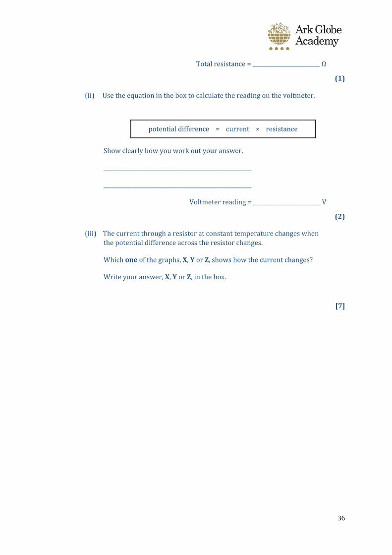
Total resistance = _________________________ Ω
(1)
(ii) Use the equation in the box to calculate the reading on the voltmeter.
potential difference = current × resistance
Show clearly how you work out your answer.
_______________________________________________________
_______________________________________________________
Voltmeter reading = _________________________ V
(2)
(iii) The current through a resistor at constant temperature changes when
the potential difference across the resistor changes.
Which one of the graphs, X, Y or Z, shows how the current changes?
Write your answer, X, Y or Z, in the box.
[7]
37
Session 8
Do Now:
1. Potential Difference can be measured by a……………………..
2. The units of PD are …………………
3. The total voltage of three 9V batteries is…………….
Difference in PD between series and parallel circuits?
PD stays the same even when it branches out into different wires.
However, PD only goes down when it goes through components.
Parallel = voltages all the same
Series = add voltages together
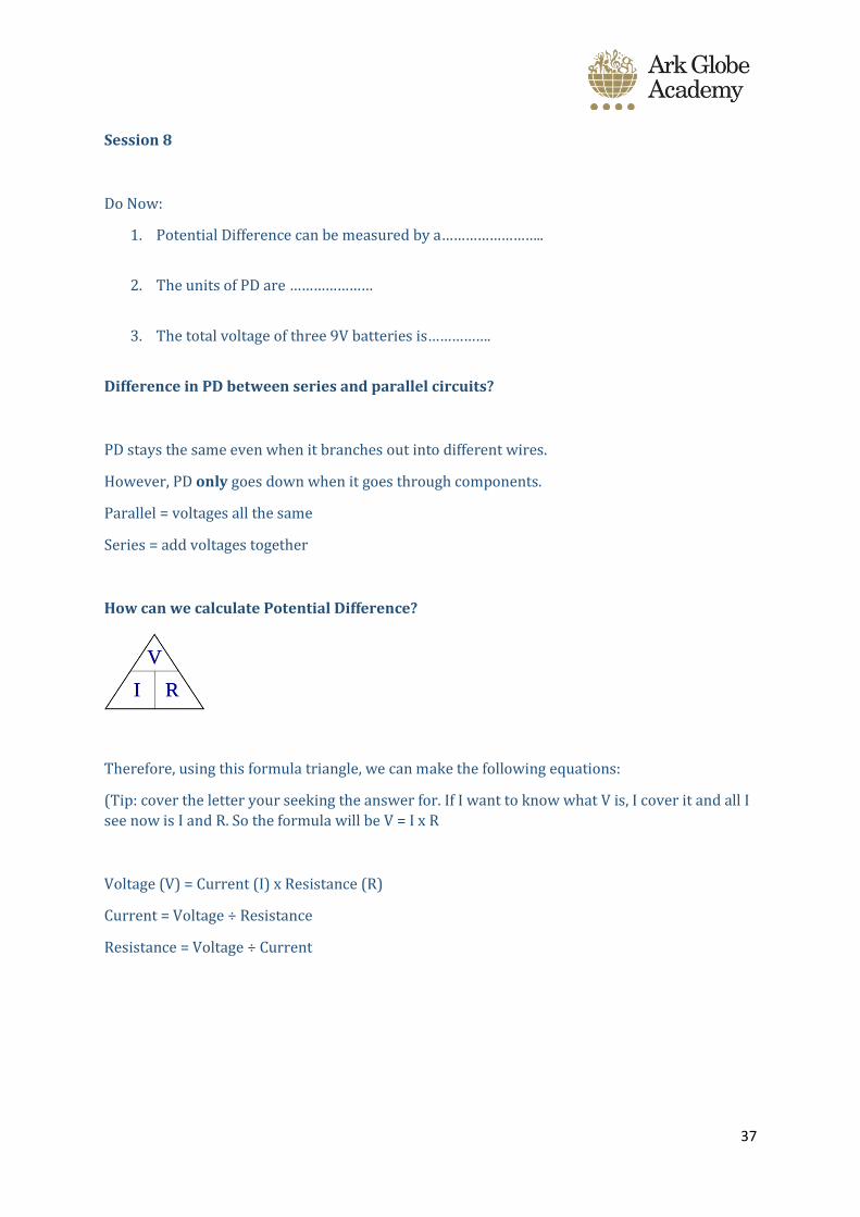
How can we calculate Potential Difference?
Therefore, using this formula triangle, we can make the following equations:
(Tip: cover the letter your seeking the answer for. If I want to know what V is, I cover it and all I
see now is I and R. So the formula will be V = I x R
Voltage (V) = Current (I) x Resistance (R)
Current = Voltage ÷ Resistance
Resistance = Voltage ÷ Current

38
1. For the following series circuits calculate the potential differences across the bulbs and the cells. Assume all bulbs are identical.
2. For the following parallel circuits calculate the potential differences across the bulbs and the cells. Assume all bulbs are identical.
1.5V
1.5V
1.5V
1.5V
1.5V
1.5V
4.5V
9V
V
3V
3V
1.5V 1.5V
1.5V
39
Circuit Calculations
1. Calculate the voltage in the following circuits:
a. Current = 2A, resistance = 10 Ohms
b. Current = 5A, resistance = 2 Ohms
c. Current = 100A, resistance = 2.3 Ohms
2. Calculate the current in the following circuits:
a. Voltage = 10V, resistance = 2 Ohms
b. Voltage = 120V, resistance = 40 Ohms
c. Voltage = 230V, resistance = 5 Ohms
3. Calculate the resistance in the following circuits:
a. Voltage = 230V, current = 10A
b. Voltage = 12V, current = 1.5A
c. Voltage = 60V, current = 2A
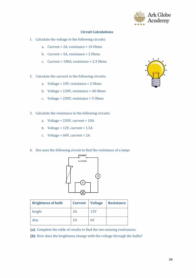
4. Des uses the following circuit to find the resistance of a lamp:
Brightness of bulb Current Voltage Resistance
bright 3A 12V
dim 2A 6V
(a) Complete the table of results to find the two missing resistances.
(b) How does the brightness change with the voltage through the bulbs?
power
supply
A
V
40
Session 9
Do Now – Answers on ppt/video
1. What is potential difference measured in?
2. What do we use to measure potential difference?
3. Potential difference is the difference in/between what?
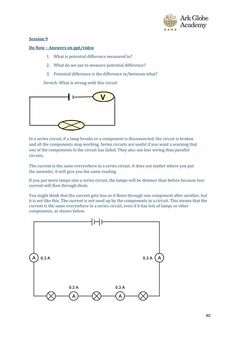
Stretch: What is wrong with this circuit
In a series circuit, if a lamp breaks or a component is disconnected, the circuit is broken
and all the components stop working. Series circuits are useful if you want a warning that
one of the components in the circuit has failed. They also use less wiring than parallel
circuits.
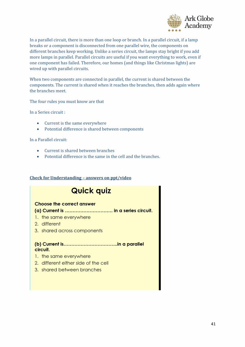
The current is the same everywhere in a series circuit. It does not matter where you put
the ammeter, it will give you the same reading.
If you put more lamps into a series circuit, the lamps will be dimmer than before because less current will flow through them.
You might think that the current gets less as it flows through one component after another, but it is not like this. The current is not used up by the components in a circuit. This means that the current is the same everywhere in a series circuit, even if it has lots of lamps or other components, as shown below.
41
In a parallel circuit, there is more than one loop or branch. In a parallel circuit, if a lamp
breaks or a component is disconnected from one parallel wire, the components on
different branches keep working. Unlike a series circuit, the lamps stay bright if you add
more lamps in parallel. Parallel circuits are useful if you want everything to work, even if
one component has failed. Therefore, our homes (and things like Christmas lights) are
wired up with parallel circuits.
When two components are connected in parallel, the current is shared between the
components. The current is shared when it reaches the branches, then adds again where
the branches meet.
The four rules you must know are that
In a Series circuit :
• Current is the same everywhere
• Potential difference is shared between components
In a Parallel circuit:
• Current is shared between branches
• Potential difference is the same in the cell and the branches.
Check for Understanding – answers on ppt/video
42
43
Session 10
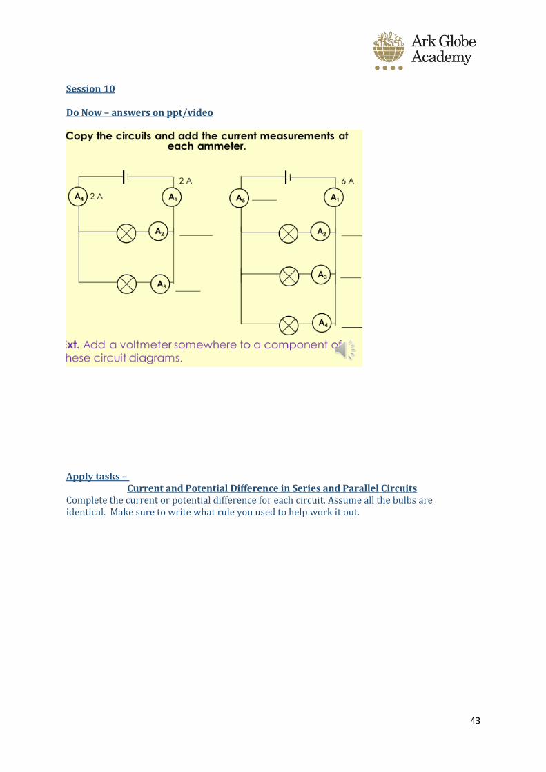
Do Now – answers on ppt/video
Apply tasks – Current and Potential Difference in Series and Parallel Circuits
Complete the current or potential difference for each circuit. Assume all the bulbs are identical. Make sure to write what rule you used to help work it out.

44
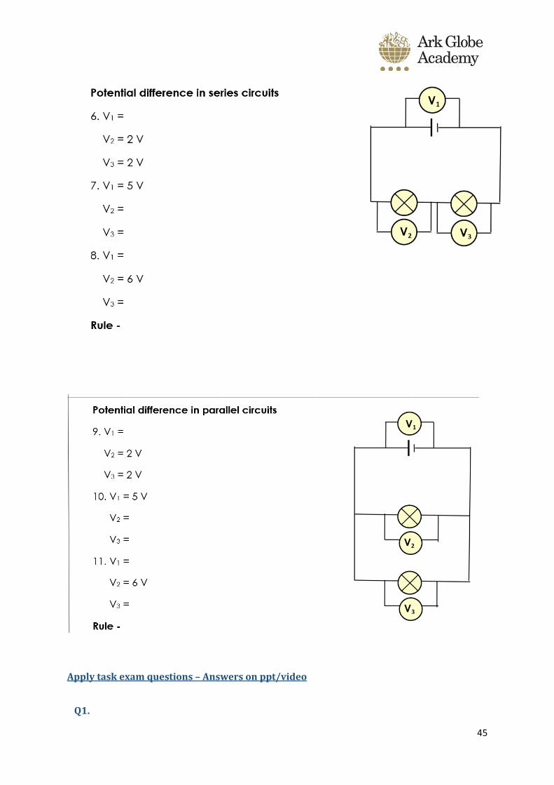
45
Apply task exam questions – Answers on ppt/video
Q1.

46
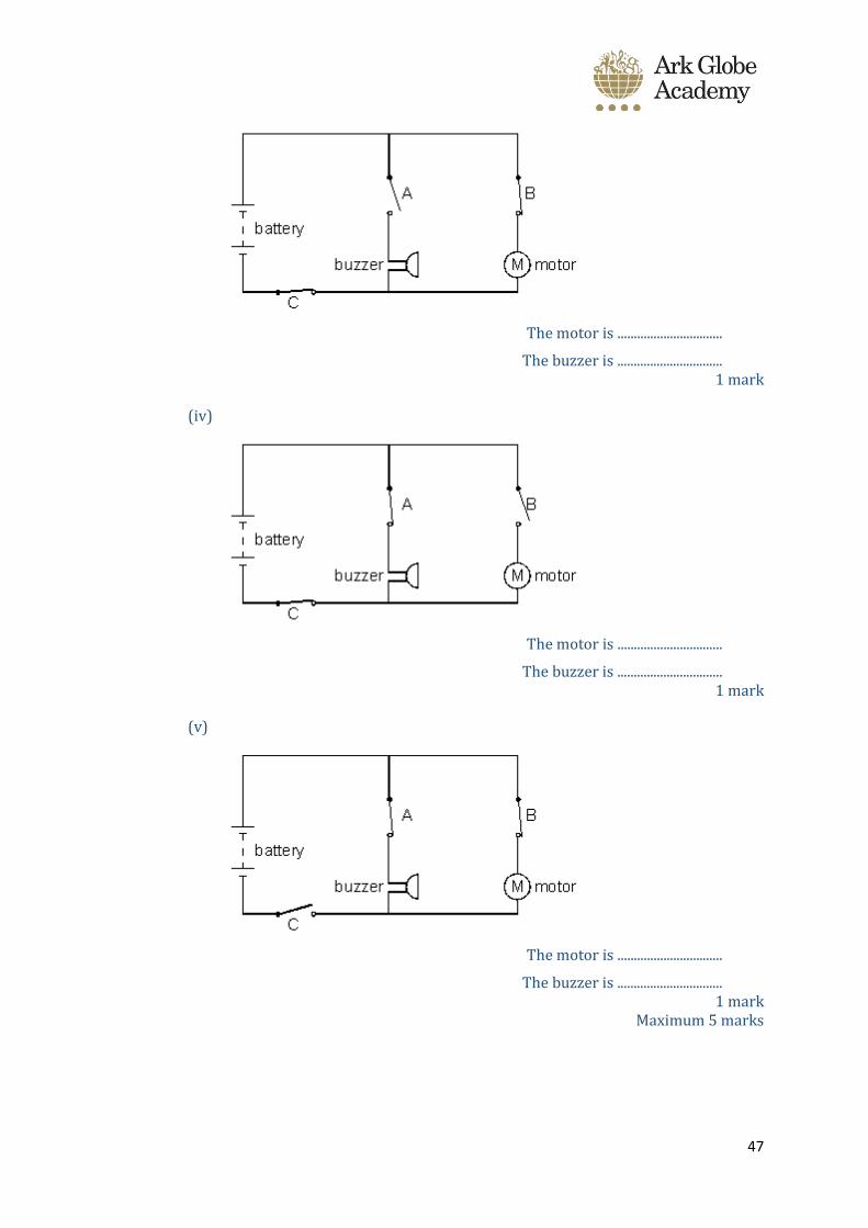
A pupil makes some electrical circuits. Each circuit contains a motor and a buzzer. The motor and the buzzer can be switched on or off by three switches, A, B and C.
Symbols for an open switch and a closed switch are shown below.
By each circuit diagram, state whether:
the motor is on or off; the buzzer is on or off.
(i)
The motor is ................................
The buzzer is ................................ 1 mark
(ii)
The motor is ................................
The buzzer is ................................ 1 mark
(iii)
47
The motor is ................................
The buzzer is ................................ 1 mark
(iv)
The motor is ................................
The buzzer is ................................ 1 mark
(v)
The motor is ................................
The buzzer is ................................ 1 mark
Maximum 5 marks
48
Mark schemes – Session 3 + 4
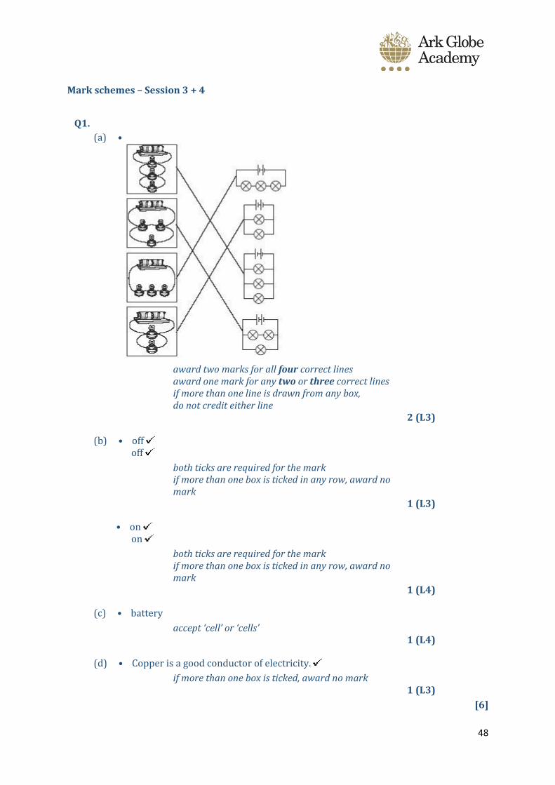
Q1.
(a) •
award two marks for all four correct lines award one mark for any two or three correct lines if more than one line is drawn from any box, do not credit either line
2 (L3)
(b) • off off
both ticks are required for the mark if more than one box is ticked in any row, award no mark
1 (L3)
• on on
both ticks are required for the mark if more than one box is ticked in any row, award no mark
1 (L4)
(c) • battery
accept ‘cell’ or ‘cells’ 1 (L4)
(d) • Copper is a good conductor of electricity.
if more than one box is ticked, award no mark 1 (L3)
[6]
49
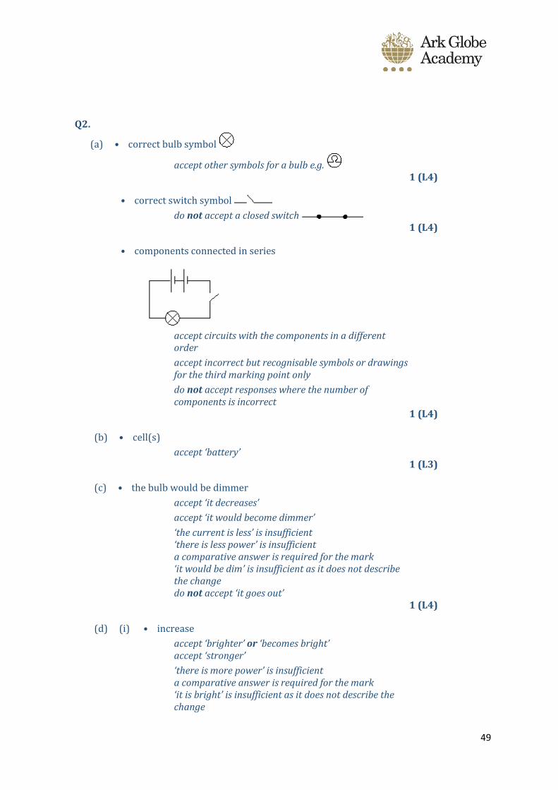
Q2.
(a) • correct bulb symbol
accept other symbols for a bulb e.g. 1 (L4)
• correct switch symbol
do not accept a closed switch 1 (L4)
• components connected in series
accept circuits with the components in a different order
accept incorrect but recognisable symbols or drawings for the third marking point only
do not accept responses where the number of components is incorrect
1 (L4)
(b) • cell(s)
accept ‘battery’ 1 (L3)
(c) • the bulb would be dimmer
accept ‘it decreases’
accept ‘it would become dimmer’
‘the current is less’ is insufficient ‘there is less power’ is insufficient a comparative answer is required for the mark ‘it would be dim’ is insufficient as it does not describe the change do not accept ‘it goes out’
1 (L4)
(d) (i) • increase
accept ‘brighter’ or ‘becomes bright’ accept ‘stronger’
‘there is more power’ is insufficient a comparative answer is required for the mark ‘it is bright’ is insufficient as it does not describe the change

50
1 (L4)
(ii) • bulbs would go out
accept ‘no brightness’ or ‘no light’ accept ‘it decreases’ accept ‘weaker’
‘not bright’ is insufficient ‘none’ or ‘nothing’ are insufficient ‘there is no power’ is insufficient ‘darker’ is insufficient
1 (L4)
[7]
Q3.
(a) J 1
(b) bulb J goes out or is off
do not accept ‘nothing happens’ 1
both bulb K and bulb L are required for the mark
bulb K lights up or is on
accept ‘bulb K is dim
bulb L lights up or is on
bulb L is dim’ 1
(c) the answer should indicate that all three bulbs are lit
J, K and L or all of them 1
[4]
Q4.
(a) (i) any one from
• it let the current or electricity flow
• current could flow through the bulb
• it completed the circuit
accept ‘the contacts came together’ 1 (L3)
(ii) all three components must be correctly connected in series
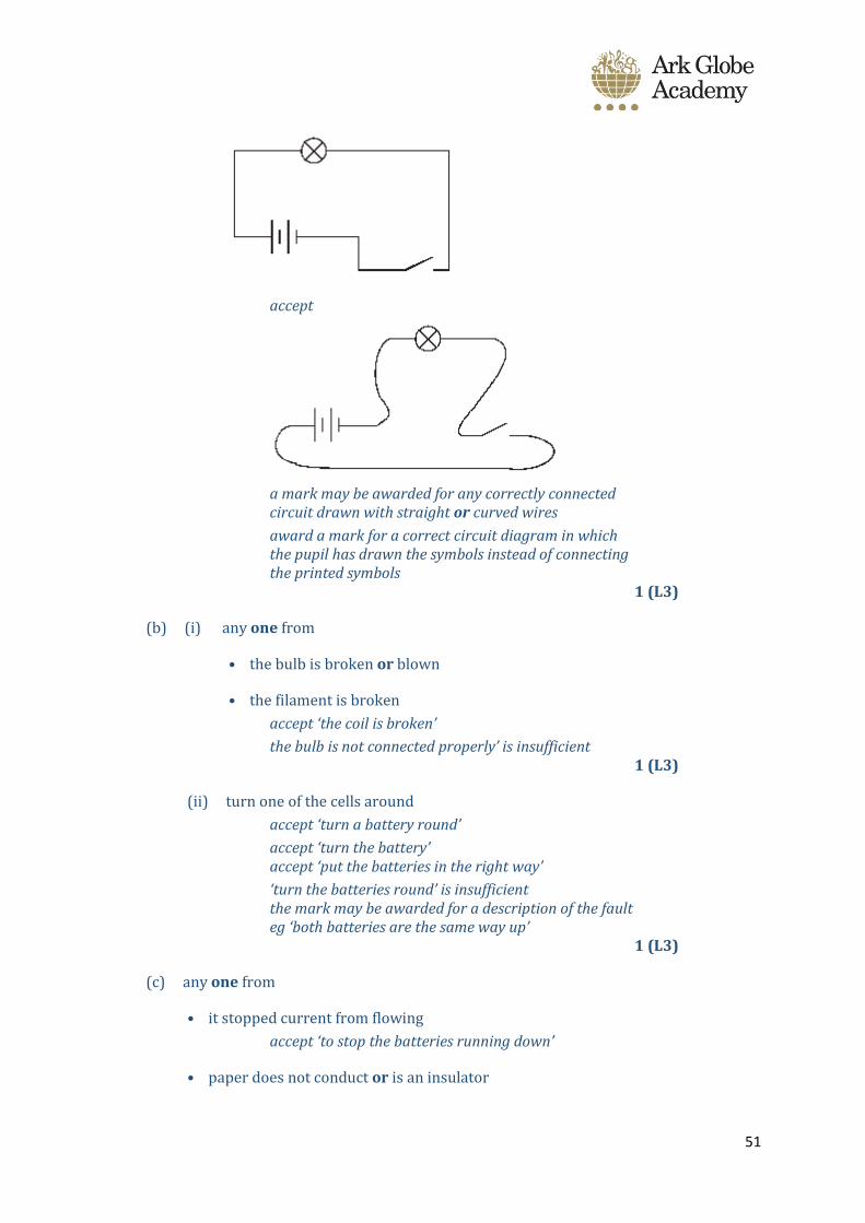
51
accept
a mark may be awarded for any correctly connected circuit drawn with straight or curved wires
award a mark for a correct circuit diagram in which the pupil has drawn the symbols instead of connecting the printed symbols
1 (L3)
(b) (i) any one from
• the bulb is broken or blown
• the filament is broken
accept ‘the coil is broken’
the bulb is not connected properly’ is insufficient 1 (L3)
(ii) turn one of the cells around
accept ‘turn a battery round’
accept ‘turn the battery’ accept ‘put the batteries in the right way’
‘turn the batteries round’ is insufficient the mark may be awarded for a description of the fault eg ‘both batteries are the same way up’
1 (L3)
(c) any one from
• it stopped current from flowing
accept ‘to stop the batteries running down’
• paper does not conduct or is an insulator

52
• the circuit was broken or incomplete
accept ‘to stop the contacts coming together’
• so that the circuit can be completed 1 (L3)
[5]
53
Mark schemes – Session 7
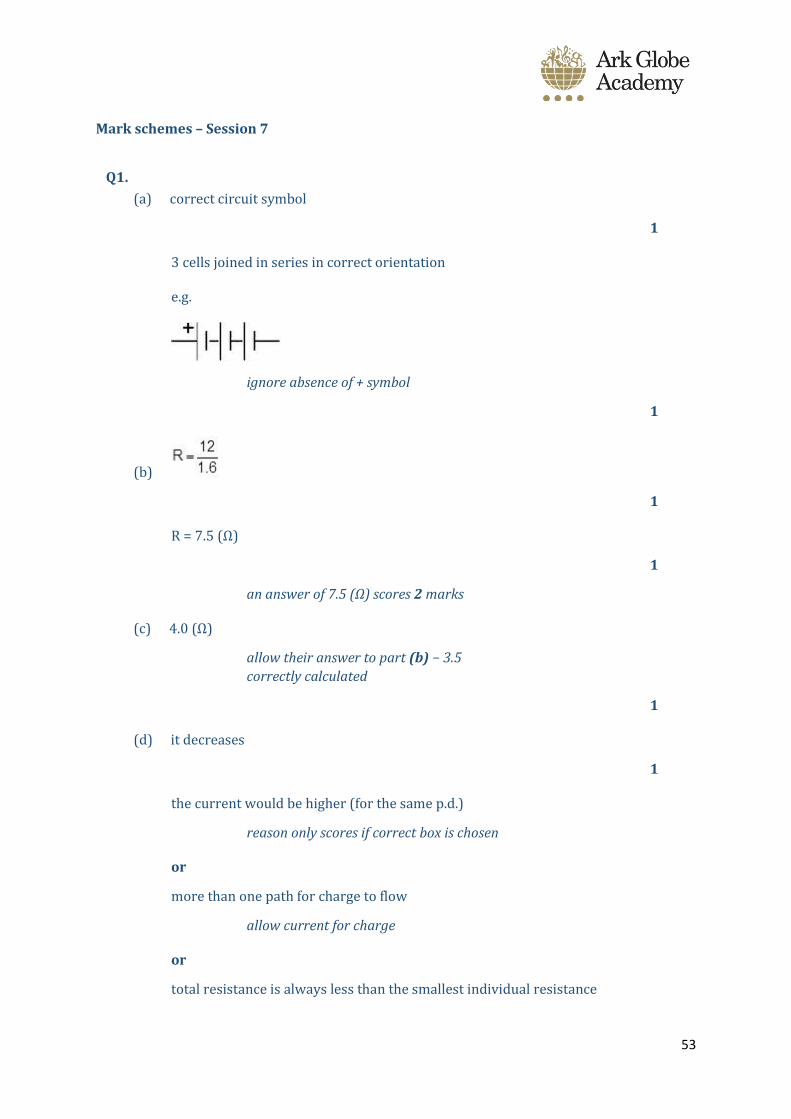
Q1.
(a) correct circuit symbol
1
3 cells joined in series in correct orientation
e.g.
ignore absence of + symbol
1
(b)
1
R = 7.5 (Ω)
1
an answer of 7.5 (Ω) scores 2 marks
(c) 4.0 (Ω)
allow their answer to part (b) − 3.5
correctly calculated
1
(d) it decreases
1
the current would be higher (for the same p.d.)
reason only scores if correct box is chosen
or
more than one path for charge to flow
allow current for charge
or
total resistance is always less than the smallest individual resistance

54
1
[7]
Q2.
L
N
M
K
all four in the correct order
2 marks for 2 correct
1 mark for 1 correct
[3]
Q3.
(a) (i) 4.5
1
(ii) 2.25 or their (a)(i) ÷ 2 correctly calculated
1
(iii) V2
1
(b) (i) 30
1
(ii) 8
allow 1 mark for correct substitution
ie 0.4 × 20
allow 1 mark for answers of 4 or 12

55
2
(iii) Y
1
56
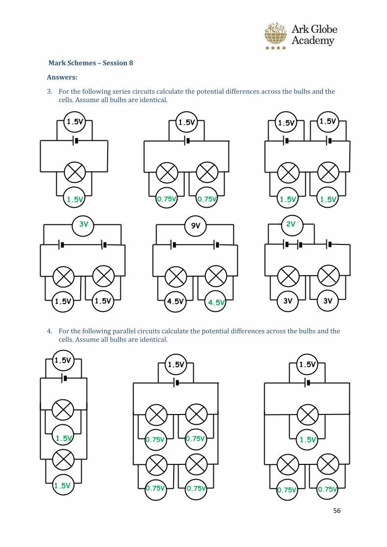
Mark Schemes – Session 8
Answers:
3. For the following series circuits calculate the potential differences across the bulbs and the cells. Assume all bulbs are identical.
4. For the following parallel circuits calculate the potential differences across the bulbs and the cells. Assume all bulbs are identical.
1.5V
1.5V
1.5V
4.5V
9V
3V
3V
1.5V 1.5V
1.5V
1.5V
1.5V
1.5V
1.5V
0.75V 0.75V 1.5V
1.5V
3V
4.5V
2V
1.5V
1.5V
0.75V 0.75V
0.75V 0.75V 1.5V
0.75V 0.75V
57
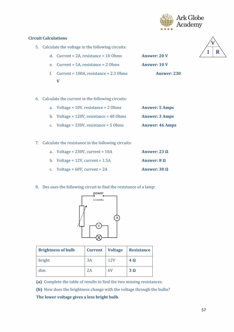
Circuit Calculations
5. Calculate the voltage in the following circuits:
d. Current = 2A, resistance = 10 Ohms Answer: 20 V
e. Current = 5A, resistance = 2 Ohms Answer: 10 V
f. Current = 100A, resistance = 2.3 Ohms Answer: 230
V
6. Calculate the current in the following circuits:
a. Voltage = 10V, resistance = 2 Ohms Answer: 5 Amps
b. Voltage = 120V, resistance = 40 Ohms Answer: 3 Amps
c. Voltage = 230V, resistance = 5 Ohms Answer: 46 Amps
7. Calculate the resistance in the following circuits:
a. Voltage = 230V, current = 10A Answer: 23 Ω
b. Voltage = 12V, current = 1.5A Answer: 8 Ω
c. Voltage = 60V, current = 2A Answer: 30 Ω
8. Des uses the following circuit to find the resistance of a lamp:
Brightness of bulb Current Voltage Resistance
bright 3A 12V 4 Ω
dim 2A 6V 3 Ω
(a) Complete the table of results to find the two missing resistances.
(b) How does the brightness change with the voltage through the bulbs?
The lower voltage gives a less bright bulb.
power
supply
A
V