YAMAHA MOTOR CO., LTD. - Altijd verbonden | Ziggomembers.chello.nl/h.hoorn6/yamaha_tenere_1vj/Yamaha...
100
4PT-28199-E7 OWNER’S MANUAL XT600E XT500E
Transcript of YAMAHA MOTOR CO., LTD. - Altijd verbonden | Ziggomembers.chello.nl/h.hoorn6/yamaha_tenere_1vj/Yamaha...

PRINTED ON RECYCLED PAPER PRINTED IN JAPAN
2001·7–0.9×1(E) !4PT-28199-E7
OWNER’S MANUAL
YAMAHA MOTOR CO., LTD.XT600EXT500E

EAU03338
INTRODUCTION
Welcome to the Yamaha world of motorcycling!
As the owner of an XT500E/XT600E, you are benefiting from Yamaha’s vast experience and newesttechnology regarding the design and manufacture of high-quality products, which have earnedYamaha a reputation for dependability.
Please take the time to read this manual thoroughly, so as to enjoy all advantages of yourXT500E/XT600E. The owner’s manual does not only instruct you in how to operate, inspect andmaintain your motorcycle, but also in how to safeguard yourself and others from trouble and injury.
In addition, the many tips given in this manual will help keep your motorcycle in the best possiblecondition. If you have any further questions, do not hesitate to contact your Yamaha dealer.
The Yamaha team wishes you many safe and pleasant rides. So, remember to put safety first!
4PT-E7 (English) 6/29/01 9:13 AM Page 1

EAU00005
IMPORTANT MANUAL INFORMATION
Particularly important information is distinguished in this manual by the following notations:
The Safety Alert Symbol means ATTENTION! BECOME ALERT! YOUR SAFETY ISINVOLVED!
Failure to follow WARNING instructions could result in severe injury or death tothe motorcycle operator, a bystander, or a person inspecting or repairing themotorcycle.
A CAUTION indicates special precautions that must be taken to avoid damage tothe motorcycle.
A NOTE provides key information to make procedures easier or clearer.
Q
w
cC
NOTE:
NOTE:8 This manual should be considered a permanent part of this motorcycle and should remain
with it even if the motorcycle is subsequently sold.8 Yamaha continually seeks advancements in product design and quality. Therefore, while this
manual contains the most current product information available at the time of printing, theremay be minor discrepancies between your motorcycle and this manual. If you have any ques-tions concerning this manual, please consult your Yamaha dealer.
4PT-E7 (English) 6/29/01 9:13 AM Page 2
IMPORTANT MANUAL INFORMATION
EW000002
w
PLEASE READ THIS MANUAL CAREFULLY AND COMPLETELY BEFORE OPERATINGTHIS MOTORCYCLE.
4PT-E7 (English) 6/29/01 9:13 AM Page 3

XT500E/XT600EOWNER’S MANUAL
©2001 by Yamaha Motor Co., Ltd.1st edition, June 2001
All rights reserved.Any reprinting or unauthorized usewithout the written permission of
Yamaha Motor Co., Ltd.is expressly prohibited.
Printed in Japan.
EAU04229
4PT-E7 (English) 6/29/01 9:13 AM Page 4

EAU00009
TABLE OF CONTENTS
1 GIVE SAFETY THE RIGHT OF WAY
2 DESCRIPTION
3 INSTRUMENT AND CONTROL FUNCTIONS
4 PRE-OPERATION CHECKS
5 OPERATION AND IMPORTANT RIDING POINTS
6 PERIODIC MAINTENANCE AND MINOR REPAIR
7 MOTORCYCLE CARE AND STORAGE
8 SPECIFICATIONS
9 CONSUMER INFORMATION
INDEX
9
8
7
6
5
4
3
2
1
4PT-E7 (English) 6/29/01 9:13 AM Page 5

4PT-E7 (English) 6/29/01 9:13 AM Page 6

Q GIVE SAFETY THE RIGHT OF WAY
GIVE SAFETY THE RIGHT OF WAY .............................................. 1-11
4PT-E7 (English) 6/29/01 9:13 AM Page 7

1-1
EAU00021
Q GIVE SAFETY THE RIGHT OF WAY
1
Motorcycles are fascinating vehicles, which can give you an unsurpassed feeling of power and free-dom. However, they also impose certain limits, which you must accept; even the best motorcycledoes not ignore the laws of physics.
Regular care and maintenance are essential for preserving value and operating condition of yourmotorcycle. Moreover, what is true for the motorcycle is also true for the rider: good performancedepends on being in good shape. Riding under the influence of medication, drugs and alcohol is, ofcourse, out of the question. Motorcycle riders—more than car drivers—must always be at their mentaland physical best. Under the influence of even small amounts of alcohol, there is a tendency to takedangerous risks.
Protective clothing is as essential for the motorcycle rider as seat belts are for car drivers and passen-gers. Always wear a complete motorcycle suit (whether made of leather or tear-resistant syntheticmaterials with protectors), sturdy boots, motorcycle gloves and a properly fitting helmet. Optimum pro-tective wear, however, should not encourage carelessness. Although full-coverage helmets and suits,in particular, create an illusion of total safety and protection, motorcyclists will always be vulnerable.Riders who lack critical self-control run the risk of going too fast and are apt to take chances. This iseven more dangerous in wet weather. The good motorcyclist rides safely, predictably and defensive-ly—avoiding all dangers, including those caused by others.
Enjoy your ride!
4PT-E7 (English) 6/29/01 9:13 AM Page 8

DESCRIPTION
Left view ........................................................................................... 2-1Right view ......................................................................................... 2-2Controls and instruments .................................................................. 2-3
2
4PT-E7 (English) 6/29/01 9:13 AM Page 9

2-1
EAU00026
DESCRIPTIONPart locations
2
1. Headlight (page 6-33)2. Fuel cock (page 3-8)3. Battery (page 6-31)4. Owner’s tool kit (page 6-1)5. Helmet holder (page 3-10)
6. Shock absorber spring preloadadjusting nut (page 3-10)
7. Fuse (page 6-32)8. Starter (choke) knob (page 3-9)9. Shift pedal (page 3-5)
1 2 3 4 5
6789
Left view
4PT-E7 (English) 6/29/01 9:13 AM Page 10

2-2
DESCRIPTION
2
10. Air filter element (page 6-13)11. Oil filter element (page 6-11)12. Engine oil filler cap (page 6-10)13. Brake pedal (page 3-5, 6-21)
10 11
13
12
Right view
4PT-E7 (English) 6/29/01 9:13 AM Page 11
2-3
DESCRIPTION
2
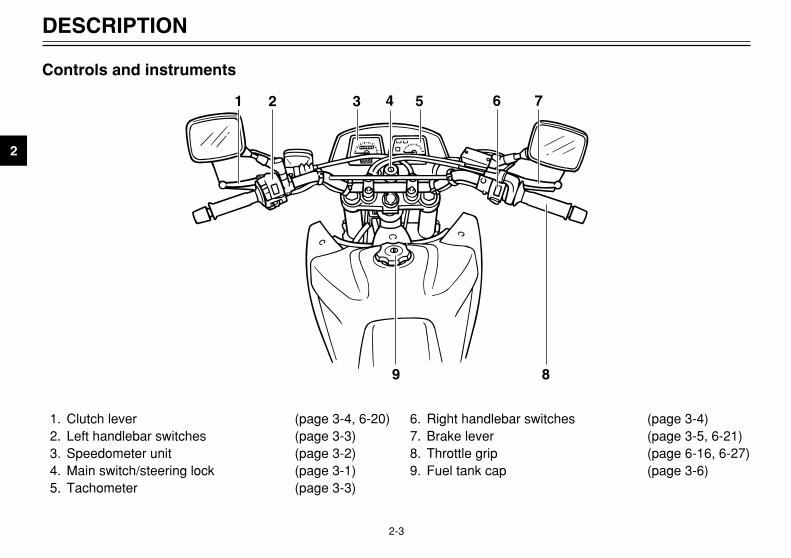
1. Clutch lever (page 3-4, 6-20)2. Left handlebar switches (page 3-3)3. Speedometer unit (page 3-2)4. Main switch/steering lock (page 3-1)5. Tachometer (page 3-3)
6. Right handlebar switches (page 3-4)7. Brake lever (page 3-5, 6-21)8. Throttle grip (page 6-16, 6-27)9. Fuel tank cap (page 3-6)
1 2 3 4 5 6 7
89
Controls and instruments
4PT-E7 (English) 6/29/01 9:13 AM Page 12

INSTRUMENT AND CONTROL FUNCTIONS
Main switch/steering lock .................................................................. 3-1Indicator lights .................................................................................. 3-2Speedometer unit ............................................................................ 3-2Tachometer ...................................................................................... 3-3Handlebar switches .......................................................................... 3-3Clutch lever ....................................................................................... 3-4Shift pedal ......................................................................................... 3-5Brake lever ....................................................................................... 3-5Brake pedal ...................................................................................... 3-5Fuel tank cap .................................................................................... 3-6Fuel ................................................................................................... 3-6Fuel cock .......................................................................................... 3-8Starter (choke) knob ......................................................................... 3-9Seat .................................................................................................. 3-9Helmet holder ................................................................................. 3-10Adjusting the shock absorber assembly ......................................... 3-10Sidestand ........................................................................................ 3-11Ignition circuit cut-off system .......................................................... 3-12
3
4PT-E7 (English) 6/29/01 9:13 AM Page 13

3-1
EAU00029
Main switch/steering lockMain switch/steering lock
The main switch/steering lock con-trols the ignition and lighting systems,and is used to lock the steering. Thevarious positions are describedbelow.
EAU00036
ONAll electrical systems are suppliedwith power, and the engine can bestarted. The key cannot be removed.
EAU00038
OFFAll electrical systems are off. The keycan be removed.
EW000016
w
Never turn the key to “OFF” or“LOCK” while the motorcycle ismoving, otherwise the electricalsystems will be switched off,which may result in loss of controlor an accident. Make sure that themotorcycle is stopped before turn-ing the key to “OFF” or “LOCK”.
EAU01590
. (Parking)The steering is locked, and the tail-light and auxiliary light are on, but allother electrical systems are off. Thekey can be removed.The steering must be locked beforethe key can be turned to “.”.
ECA00043
cC
Do not use the parking position foran extended length of time, other-wise the battery may discharge.
EAU00027
INSTRUMENT AND CONTROL FUNCTIONS
3
ONOFF
LOCK
.
EAU00040
LOCKThe steering is locked, and all electri-cal systems are off. The key can beremoved.To lock the steering
1. Turn the handlebars all the wayto the left.
2. Push the key in from the “OFF”position, and then turn it to“LOCK” while still pushing it.
3. Remove the key.
To unlock the steeringPush the key in, and then turn it to“OFF” while still pushing it.
1 2
1. Push.2. Turn.
4PT-E7 (English) 6/29/01 9:13 AM Page 14

3-2
INSTRUMENT AND CONTROL FUNCTIONS
3
EAU00056
Indicator lightsIndicator lights
EAU00063
High beam indicator light “&”High beam indicator light
This indicator light comes on whenthe high beam of the headlight isswitched on.
EAU00061
Neutral indicator light “N”Neutral indicator light
This indicator light comes on whenthe transmission is in the neutralposition.
EAU00057
Turn signal indicator light “5”Turn signal indicator light
This indicator light flashes when theturn signal switch is pushed to the leftor right.
1 2
3
&
5
N
1. High beam indicator light “&”2. Neutral indicator light “N”3. Turn signal indicator light “5”
EAU00095
Speedometer unit Speedometer unit
The speedometer unit is equippedwith a speedometer, an odometerand a tripmeter. The speedometershows riding speed. The odometershows the total distance traveled.The tripmeter shows the distancetraveled since it was last set to zerowith the reset knob. The tripmetercan be used to estimate the distancethat can be traveled with a full tank offuel. This information will enable youto plan future fuel stops.
1 2
4
3
1. Speedometer2. Odometer3. Tripmeter4. Reset knob
4PT-E7 (English) 6/29/01 9:13 AM Page 15

3-3
EAU00102
TachometerTachometer
The tachometer allows the rider tomonitor the engine speed and keep itwithin the ideal power range.
EC000003
cC
Do not operate the engine in thetachometer red zone.Red zone: 7,000 r/min and above
EAU03888
Dimmer switch “%/&”Dimmer switch
Set this switch to “&” for the highbeam and to “%” for the low beam.
EAU03889
Turn signal switch “4/6”Turn signal switch
To signal a right-hand turn, push thisswitch to “6”. To signal a left-handturn, push this switch to “4”. Whenreleased, the switch returns to thecenter position. To cancel the turnsignal lights, push the switch in afterit has returned to the center position.
EAU00129
Horn switch “*”Horn switch
Press this switch to sound the horn.
INSTRUMENT AND CONTROL FUNCTIONS
3
1
5
& N
a
1. Tachometera. Red zone
EAU00118
Handlebar switchesHandlebar switches
EAU03898
Light switch “9/'/:”Light switch
Set this switch to “'” to turn on theauxiliary light, meter lighting and tail-light. Set the switch to “:” to turn onthe headlight also. Set the switch to“9” to turn off all the lights.
EAU00119
Pass switch “&”Pass switch
Press this switch to flash the head-light.
45
1 2 3
*
1. Light switch “9 /'/:”2. Pass switch “&”3. Dimmer switch “%/&”4. Turn signal switch “4/6”5. Horn switch “*”
4PT-E7 (English) 6/29/01 9:13 AM Page 16

3-4
INSTRUMENT AND CONTROL FUNCTIONS
3
EAU03890
Engine stop switch “$/#”Engine stop switch
Set this switch to “#” before startingthe engine. Set this switch to “$” tostop the engine in case of an emer-gency, such as when the motorcycleoverturns or when the throttle cable isstuck.
EAU00143
Start switch “,”Start switch
Push this switch to crank the enginewith the starter.
EC000005
cC
See page 5-1 for starting instruc-tions prior to starting the engine.
12
,
1. Engine stop switch “$/#”2. Start switch “,”
EAU00152
Clutch leverClutch lever
The clutch lever is located at the lefthandlebar grip. To disengage theclutch, pull the lever toward the han-dlebar grip. To engage the clutch,release the lever. The lever shouldbe pulled rapidly and released slowlyfor smooth clutch operation.The clutch lever is equipped with aclutch switch, which is part of the igni-tion circuit cut-off system. (See page3-12 for an explanation of the ignitioncircuit cut-off system.)
1
1. Clutch lever
4PT-E7 (English) 6/29/01 9:13 AM Page 17

3-5
EAU00157
Shift pedalShift pedal
The shift pedal is located on the leftside of the engine and is used incombination with the clutch leverwhen shifting the gears of the 5-speed constant-mesh transmissionequipped on this motorcycle.
INSTRUMENT AND CONTROL FUNCTIONS
3
1
1. Shift pedal
EAU00158
Brake leverBrake lever
The brake lever is located at the righthandlebar grip. To apply the frontbrake, pull the lever toward the han-dlebar grip.
1
1. Brake lever
EAU00162
Brake pedalBrake pedal
The brake pedal is on the right sideof the motorcycle. To apply the rearbrake, press down on the brakepedal.
1
1. Brake pedal
4PT-E7 (English) 6/29/01 9:13 AM Page 18

3-6
INSTRUMENT AND CONTROL FUNCTIONS
3
EAU00177
Fuel tank capFuel tank cap
To remove the fuel tank cap1. Insert the key into the lock and
turn it 1/4 turn counterclockwise.2. Turn the fuel tank cap 1/3 turn
counterclockwise and pull it off.
To install the fuel tank cap1. Insert the fuel tank cap into the
tank opening with the key insert-ed in the lock, and then turn thecap 1/3 turn clockwise.
2. Turn the key 1/4 turn clockwise,and then remove it.
NOTE:The fuel tank cap cannot be installedunless the key is in the lock. In addi-tion, the key cannot be removed if thecap is not properly installed andlocked.
EW000023
w
Make sure that the fuel tank cap isproperly closed and locked beforeriding.
ba
a. Unlock.b. Open.
EAU03753
FuelFuel
Make sure that there is sufficient fuelin the tank. Fill the fuel tank to thebottom of the filler tube as shown.
EW000130
w
8 Do not overfill the fuel tank,otherwise it may overflowwhen the fuel warms up andexpands.
8 Avoid spilling fuel on the hotengine.
21
1. Filler tube2. Fuel level
4PT-E7 (English) 6/29/01 9:13 AM Page 19
3-7
EAU00185
cC
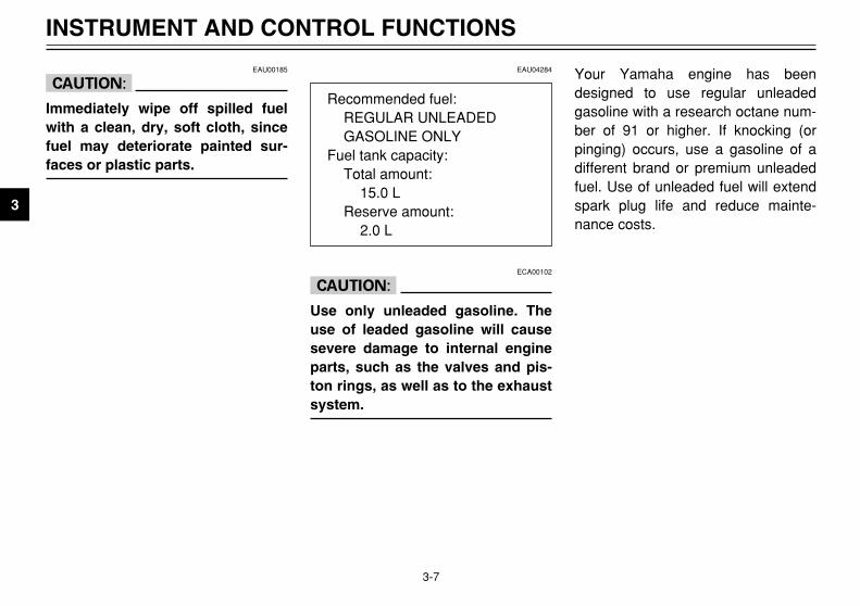
Immediately wipe off spilled fuelwith a clean, dry, soft cloth, sincefuel may deteriorate painted sur-faces or plastic parts.
EAU04284
ECA00102
cC
Use only unleaded gasoline. Theuse of leaded gasoline will causesevere damage to internal engineparts, such as the valves and pis-ton rings, as well as to the exhaustsystem.
Your Yamaha engine has beendesigned to use regular unleadedgasoline with a research octane num-ber of 91 or higher. If knocking (orpinging) occurs, use a gasoline of adifferent brand or premium unleadedfuel. Use of unleaded fuel will extendspark plug life and reduce mainte-nance costs.
INSTRUMENT AND CONTROL FUNCTIONS
3
Recommended fuel:REGULAR UNLEADED GASOLINE ONLY
Fuel tank capacity:Total amount:
15.0 LReserve amount:
2.0 L
4PT-E7 (English) 6/29/01 9:13 AM Page 20

3-8
INSTRUMENT AND CONTROL FUNCTIONS
3
EAU03050
Fuel cockFuel cock
The fuel cock supplies fuel from thetank to the carburetor while filtering italso.The fuel cock has three positions:
OFFWith the lever in this position, fuel willnot flow. Always return the lever tothis position when the engine is notrunning.
RES
ONFUEL
OFF
1
1. Arrow mark pointing over “OFF”
RESThis indicates reserve. If you run outof fuel while riding, move the lever tothis position. Fill the tank at the firstopportunity. Be sure to set the leverback to “ON” after refueling!
OFF
ONFUEL
RES
1
RES
1. Arrow mark pointing over “RES”
ONWith the lever in this position, fuelflows to the carburetor. Normal ridingis done with the lever in this position.
ONFUEL
RES
OFF
1ON
1. Arrow mark pointing over “ON”
RES: reserve positionON: normal positionOFF: closed position
4PT-E7 (English) 6/29/01 9:13 AM Page 21
3-9
EAU04038
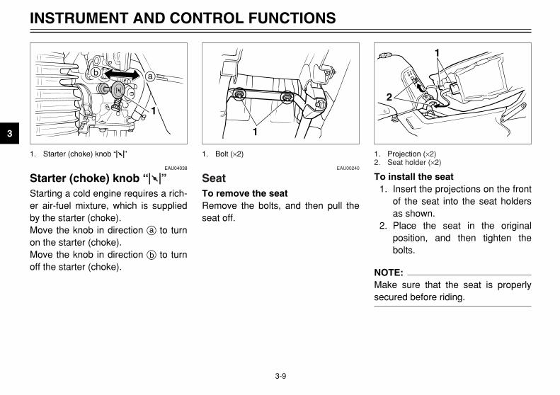
Starter (choke) knob “1”Starter (choke) knob
Starting a cold engine requires a rich-er air-fuel mixture, which is suppliedby the starter (choke).Move the knob in direction a to turnon the starter (choke).Move the knob in direction b to turnoff the starter (choke).
INSTRUMENT AND CONTROL FUNCTIONS
3
1
b a
1. Starter (choke) knob “1”
To install the seat1. Insert the projections on the front
of the seat into the seat holdersas shown.
2. Place the seat in the originalposition, and then tighten thebolts.
NOTE:Make sure that the seat is properlysecured before riding.
1
2
1. Projection (×2)2. Seat holder (×2)
EAU00240
SeatSeat
To remove the seatRemove the bolts, and then pull theseat off.
1
1. Bolt (×2)
4PT-E7 (English) 6/29/01 9:13 AM Page 22

3-10
INSTRUMENT AND CONTROL FUNCTIONS
3
EAU00260
Helmet holderHelmet holder
To open the helmet holder, insert thekey into the lock, and then turn thekey as shown.To lock the helmet holder, place it inthe original position, and then removethe key.
EW000030
w
Never ride with a helmet attachedto the helmet holder, since the hel-met may hit objects, causing lossof control and possibly an acci-dent.
1
a
1. Helmet holdera. Open.
EAU03591
Adjusting the shockabsorber assemblyShock absorber assembly, adjusting
This shock absorber assembly isequipped with a spring preloadadjusting nut.
EC000015
cC
Never attempt to turn an adjustingmechanism beyond the maximumor minimum settings.
Adjust the spring preload as follows.1. Loosen the locknut.
a
b
1
2
1. Locknut2. Adjusting nut
2. To increase the spring preloadand thereby harden the suspen-sion, turn the adjusting nut indirection a. To decrease thespring preload and thereby soft-en the suspension, turn theadjusting nut in direction b.
NOTE:The spring preload setting is deter-mined by measuring distance A,shown in the illustration. The shorterdistance A is, the lower the springpreload; the longer distance A is, thehigher the spring preload.
A
4PT-E7 (English) 6/29/01 9:13 AM Page 23

3-11
3. Tighten the locknut to the speci-fied torque.
EC000018
cC
Always tighten the locknut againstthe adjusting nut, and then tightenthe locknut to the specified torque.
EAU00315
w
This shock absorber containshighly pressurized nitrogen gas.For proper handling, read andunderstand the following informa-tion before handling the shockabsorber. The manufacturer can-not be held responsible for proper-ty damage or personal injury thatmay result from improper han-dling.8 Do not tamper with or attempt
to open the gas cylinder.8 Do not subject the shock
absorber to an open flame orother high heat sources, other-wise it may explode due toexcessive gas pressure.
8 Do not deform or damage thegas cylinder in any way, asthis will result in poor damp-ing performance.
8 Always have a Yamaha dealerservice the shock absorber.
EAU00330
SidestandSidestand
The sidestand is located on the leftside of the frame. Raise the side-stand or lower it with your foot whileholding the motorcycle upright.
NOTE:The built-in sidestand switch is part ofthe ignition circuit cut-off system,which cuts the ignition in certain situ-ations. (See further down for anexplanation of the ignition circuit cut-off system.)
INSTRUMENT AND CONTROL FUNCTIONS
3
Spring preload:Minimum (soft):
Distance A = 1 mmStandard:
Distance A = 5.5 mm Maximum (hard):
Distance A = 12 mm
Tightening torque:Locknut:
42 Nm (4.2 m0kgf)
4PT-E7 (English) 6/29/01 9:13 AM Page 24

3-12
INSTRUMENT AND CONTROL FUNCTIONS
3
EW000044
w
The motorcycle must not be riddenwith the sidestand down, or if thesidestand cannot be properlymoved up (or does not stay up),otherwise the sidestand could con-tact the ground and distract theoperator, resulting in a possibleloss of control. Yamaha’s ignitioncircuit cut-off system has beendesigned to assist the operator infulfilling the responsibility of rais-ing the sidestand before startingoff. Therefore, check this systemregularly as described below andhave a Yamaha dealer repair it if itdoes not function properly.
EAU03720
Ignition circuit cut-off systemIgnition circuit cut-off system
The ignition circuit cut-off system(comprising the sidestand switch,clutch switch and neutral switch) hasthe following functions.8 It prevents starting when the
transmission is in gear and thesidestand is up, but the clutchlever is not pulled.
8 It prevents starting when thetransmission is in gear and theclutch lever is pulled, but thesidestand is still down.
8 It cuts the running engine whenthe transmission is in gear andthe sidestand is moved down.
Periodically check the operation ofthe ignition circuit cut-off systemaccording to the following procedure.
EW000045
w
If a malfunction is noted, have aYamaha dealer check the systembefore riding.
4PT-E7 (English) 6/29/01 9:13 AM Page 25

3-13
INSTRUMENT AND CONTROL FUNCTIONS
3
With the engine turned off:1. Move the sidestand down.2. Make sure that the engine stop switch is set to “#”.3. Turn the key to “ON”. 4. Shift the transmission into the neutral position.5. Push the start switch.Does the engine start?
The neutral switch may be defective.The motorcycle should not be ridden until checked by a Yamaha dealer.
With the engine still running:6. Move the sidestand up.7. Keep the clutch lever pulled.8. Shift the transmission into gear.9. Move the sidestand down.Does the engine stall?
After the engine has stalled:10. Move the sidestand up.11. Keep the clutch lever pulled.12. Push the start switch.Does the engine start?
The sidestand switch may be defective.The motorcycle should not be ridden until checked by a Yamaha dealer.
The clutch switch may be defective.The motorcycle should not be ridden until checked by a Yamaha dealer.
NO
NOTE:This check is most reliable if performed witha warmed-up engine.
YES
YES NO
The system is OK. The motorcycle can be ridden.
YES NO
4PT-E7 (English) 6/29/01 9:13 AM Page 26

PRE-OPERATION CHECKS
Pre-operation check list .................................................................... 4-1
4
4PT-E7 (English) 6/29/01 9:13 AM Page 27

4-1
EAU01114
PRE-OPERATION CHECKS
4
The condition of a vehicle is the owner’s responsibility. Vital components can start to deteriorate quickly and unexpect-edly, even if the vehicle remains unused (for example, as a result of exposure to the elements). Any damage, fluid leak-age or loss of tire air pressure could have serious consequences. Therefore, it is very important, in addition to a thor-ough visual inspection, to check the following points before each ride.
EAU03439
Pre-operation check listPre-operation check list
ITEM CHECKS PAGE
Fuel• Check fuel level in fuel tank.• Refuel if necessary.• Check fuel line for leakage.
3-6–3-7
Engine oil• Check oil level in engine.• If necessary, add recommended oil to specified level.• Check vehicle for oil leakage.
6-10–6-13
Front brake
• Check operation.• If soft or spongy, have Yamaha dealer bleed hydraulic system.• Check lever free play.• Adjust if necessary.• Check fluid level in reservoir.• If necessary, add recommended brake fluid to specified level.• Check hydraulic system for leakage.
3-5, 6-21–6-24
Rear brake
• Check operation.• If soft or spongy, have Yamaha dealer bleed hydraulic system.• Check fluid level in reservoir.• If necessary, add recommended brake fluid to specified level.• Check hydraulic system for leakage.
3-5, 6-21–6-24
4PT-E7 (English) 6/29/01 9:13 AM Page 28

4-2
PRE-OPERATION CHECKS
4
Clutch
• Check operation.• Lubricate cable if necessary.• Check lever free play.• Adjust if necessary.
3-4, 6-20
Throttle grip• Make sure that operation is smooth.• Check free play.• If necessary, have Yamaha dealer make adjustment or lubricate.
6-16, 6-27
Control cables • Make sure that operation is smooth.• Lubricate if necessary. 6-27
Drive chain
• Check chain slack.• Adjust if necessary.• Check chain condition.• Lubricate if necessary.
6-25–6-26
Wheels and tires
• Check for damage.• Check tire condition and tread depth.• Check air pressure.• Correct if necessary.
6-16–6-19
Brake and shift pedals • Make sure that operation is smooth.• Lubricate pedal pivoting points if necessary. 6-28
Brake and clutch levers • Make sure that operation is smooth.• Lubricate lever pivoting points if necessary. 6-28
Sidestand • Make sure that operation is smooth.• Lubricate pivot if necessary. 6-28
ITEM CHECKS PAGE
4PT-E7 (English) 6/29/01 9:13 AM Page 29

4-3
PRE-OPERATION CHECKS
4
Chassis fasteners • Make sure that all nuts, bolts and screws are properly tightened.• Tighten if necessary. —
Instruments, lights, signals and switches
• Check operation. • Correct if necessary. 3-1–3-4, 6-33–6-36
Sidestand switch • Check operation of ignition circuit cut-off system.• If system is defective, have Yamaha dealer check vehicle. 3-11–3-13
ITEM CHECKS PAGE
NOTE:Pre-operation checks should be made each time the motorcycle is used. Such an inspection can be accomplished in avery short time; and the added safety it assures is more than worth the time involved.
EWA00033
w
If any item in the Pre-operation check list is not working properly, have it inspected and repaired before operat-ing the motorcycle.
4PT-E7 (English) 6/29/01 9:13 AM Page 30

OPERATION AND IMPORTANT RIDING POINTS
Starting the engine ........................................................................... 5-1Starting a warm engine ..................................................................... 5-2Shifting .............................................................................................. 5-3Recommended shift points (for Switzerland only) ............................ 5-3Tips for reducing fuel consumption .................................................. 5-4Engine break-in ................................................................................ 5-4Parking ............................................................................................. 5-5
5
4PT-E7 (English) 6/29/01 9:13 AM Page 31

1. Turn the fuel cock lever to “ON”.2. Turn the key to “ON” and make
sure that the engine stop switchis set to “#”.
3. Shift the transmission into theneutral position.
NOTE:When the transmission is in the neu-tral position, the neutral indicator lightshould be on, otherwise have aYamaha dealer check the electricalcircuit.
4. Turn the starter (choke) on andcompletely close the throttle.(See page 3-9 for starter (choke)operation.)
5. Start the engine by pushing thestart switch.
5-1
EAU00372
OPERATION AND IMPORTANT RIDING POINTS
5
EAU00373
w
8 Become thoroughly familiarwith all operating controls andtheir functions before riding.Consult a Yamaha dealerregarding any control or func-tion that you do not thorough-ly understand.
8 Never start the engine or oper-ate it in a closed area for anylength of time. Exhaust fumesare poisonous, and inhalingthem can cause loss of con-sciousness and death within ashort time. Always make surethat there is adequate ventila-tion.
8 Before starting out, make surethat the sidestand is up. If thesidestand is not raised com-pletely, it could contact theground and distract the opera-tor, resulting in a possible lossof control.
EAU03515
Starting the engineStarting the engine
In order for the ignition circuit cut-offsystem to enable starting, one of thefollowing conditions must be met:8 The transmission is in the neutral
position.8 The transmission is in gear with
the clutch lever pulled and thesidestand up.
EW000054
w
8 Before starting the engine,check the function of the igni-tion circuit cut-off systemaccording to the proceduredescribed on page 3-13.
8 Never ride with the sidestanddown.
4PT-E7 (English) 6/29/01 9:13 AM Page 32

5-2
OPERATION AND IMPORTANT RIDING POINTS
5
7. When the engine is warm, turnthe starter (choke) off.
NOTE:The engine is warm when it respondsnormally to the throttle with the starter(choke) turned off.
EAU01258
Starting a warm engineEngine, starting a warm
Follow the same procedure as forstarting a cold engine with the excep-tion that the starter (choke) is notrequired when the engine is warm.
NOTE:If the engine fails to start, release thestart switch, wait a few seconds, andthen try again. Each starting attemptshould be as short as possible to pre-serve the battery. Do not crank theengine more than 10 seconds on anyone attempt.
6. After starting the engine, movethe starter (choke) knob backhalfway.
ECA00055
cC
For maximum engine life, alwayswarm the engine up before startingoff. Never accelerate hard whenthe engine is cold!
4PT-E7 (English) 6/29/01 9:13 AM Page 33

5-3
OPERATION AND IMPORTANT RIDING POINTS
5
EAU00423
ShiftingShifting
Shifting gears lets you control theamount of engine power available forstarting off, accelerating, climbinghills, etc.The gear positions are shown in theillustration.
NOTE:To shift the transmission into the neu-tral position, press the shift pedaldown repeatedly until it reaches theend of its travel, and then slightlyraise it.
EC000048
cC
8 Even with the transmission inthe neutral position, do notcoast for long periods of timewith the engine off, and do nottow the motorcycle for longdistances. The transmission isproperly lubricated only whenthe engine is running.Inadequate lubrication maydamage the transmission.
8 Always use the clutch whilechanging gears to avoid dam-aging the engine, transmis-sion, and drive train, which arenot designed to withstand theshock of forced shifting.
EAU02941
Recommended shift points(for Switzerland only)Shift points (for Switzerland only)
The recommended shift points duringacceleration are shown in the tablebelow.
NOTE:When shifting down two gears at atime, reduce the speed accordingly(e.g., down to 35 km/h when shiftingfrom 4th to 2nd gear).
1
5432N1
1. Shift pedalN. Neutral position
Shift point (km/h)
1st → 2nd 232nd → 3rd 363rd → 4th 504th → 5th 60
4PT-E7 (English) 6/29/01 9:13 AM Page 34

5-4
OPERATION AND IMPORTANT RIDING POINTS
5
EAU00424
Tips for reducing fuel consumptionFuel consumption, tips for reducing
Fuel consumption depends largely onyour riding style. Consider the follow-ing tips to reduce fuel consumption:8 Thoroughly warm up the engine.8 Turn the starter (choke) off as
soon as possible.8 Shift up swiftly, and avoid high
engine speeds during accelera-tion.
8 Do not rev the engine while shift-ing down, and avoid high enginespeeds with no load on theengine.
8 Turn the engine off instead of let-ting it idle for an extended lengthof time (e.g., in traffic jams, attraffic lights or at railroad cross-ings).
EAU01128
Engine break-inEngine break-in
There is never a more important peri-od in the life of your engine than theperiod between 0 and 1,600 km. Forthis reason, you should read the fol-lowing material carefully.Since the engine is brand new, donot put an excessive load on it for thefirst 1,600 km. The various parts inthe engine wear and polish them-selves to the correct operating clear-ances. During this period, prolongedfull-throttle operation or any conditionthat might result in engine overheat-ing must be avoided.
EAU04315
0–1,000 km Avoid prolonged operation above4,000 r/min.
1,000–1,600 km Avoid prolonged operation above5,000 r/min.
ECA00058
cC
After 1,000 km of operation, theengine oil must be changed, andthe oil filter element replaced.
1,600 km and beyondThe vehicle can now be operatednormally.
4PT-E7 (English) 6/29/01 9:13 AM Page 35

5-5
OPERATION AND IMPORTANT RIDING POINTS
5
EC000053
cC
8 Keep the engine speed out ofthe tachometer red zone.
8 If any engine trouble shouldoccur during the engine break-in period, immediately have aYamaha dealer check the vehi-cle.
EAU00457
ParkingParking
When parking, stop the engine,remove the key from the main switch,and then turn the fuel cock lever to“OFF”.
EW000058
w
8 Since the engine and exhaustsystem can become very hot,park in a place where pedestri-ans or children are not likelyto touch them.
8 Do not park on a slope or onsoft ground, otherwise themotorcycle may overturn.
4PT-E7 (English) 6/29/01 9:13 AM Page 36

PERIODIC MAINTENANCE AND MINOR REPAIR
Owner’s tool kit ................................................ 6-1Periodic maintenance and lubrication chart ..... 6-3Removing and installing the cowling
and panels .................................................... 6-6Checking the spark plug .................................. 6-8Engine oil and oil filter element ...................... 6-10Cleaning the air filter element ........................ 6-13Adjusting the carburetor ................................. 6-14Adjusting the engine idling speed ................... 6-15Adjusting the throttle cable free play .............. 6-16Adjusting the valve clearance ........................ 6-16Tires ............................................................... 6-16Spoke wheels ................................................ 6-19Adjusting the clutch lever free play ................ 6-20Adjusting the brake lever free play ................. 6-21Adjusting the brake pedal position ................. 6-21Adjusting the rear brake light switch .............. 6-22Checking the front and rear brake pads ........ 6-22Checking the brake fluid level ........................ 6-23Changing the brake fluid ................................ 6-24Drive chain slack ............................................ 6-25Lubricating the drive chain ............................. 6-26Checking and lubricating the cables .............. 6-27
Checking and lubricating the throttle grip and cable .................................................... 6-27
Checking and lubricating the brake and shift pedals .................................................. 6-28
Checking and lubricating the brake and clutch levers ................................................ 6-28
Checking and lubricating the sidestand ......... 6-28Lubricating the rear suspension ..................... 6-29Checking the front fork ................................... 6-29Checking the steering .................................... 6-30Checking the wheel bearings ......................... 6-30Battery ............................................................ 6-31Replacing the fuse ......................................... 6-32Replacing the headlight bulb ......................... 6-33Replacing a turn signal light bulb ................... 6-35Replacing the tail/brake light bulb .................. 6-35Supporting the motorcycle ............................. 6-36Front wheel ................................................... 6-37Rear wheel ..................................................... 6-39Troubleshooting ............................................. 6-41Troubleshooting chart .................................... 6-42
6
4PT-E7 (English) 6/29/01 9:13 AM Page 37

6-1
EAU00462
PERIODIC MAINTENANCE AND MINOR REPAIR
6
EAU01175
Owner’s tool kitTool kit
The owner’s tool kit is located behindpanel A. (See page 6-7 for panelremoval and installation procedures.)The service information included inthis manual and the tools provided inthe owner’s tool kit are intended toassist you in the performance of pre-ventive maintenance and minorrepairs. However, additional toolssuch as a torque wrench may be nec-essary to perform certain mainte-nance work correctly.
EW000060
w
If you are not familiar with motor-cycle maintenance work, have aYamaha dealer do it for you.
EAU00464
Safety is an obligation of the owner.Periodic inspection, adjustment andlubrication will keep your vehicle inthe safest and most efficient condi-tion possible. The most importantpoints of inspection, adjustment, andlubrication are explained on the fol-lowing pages.The intervals given in the periodicmaintenance and lubrication chartshould be simply considered as ageneral guide under normal ridingconditions. However, DEPENDINGON THE WEATHER, TERRAIN,GEOGRAPHICAL LOCATION, ANDINDIVIDUAL USE, THE MAINTE-NANCE INTERVALS MAY NEED TOBE SHORTENED.
1
1. Owner’s tool kit
4PT-E7 (English) 6/29/01 9:13 AM Page 38
6-2
PERIODIC MAINTENANCE AND MINOR REPAIR
6
NOTE:If you do not have the tools or experi-ence required for a particular job,have a Yamaha dealer perform it foryou.
EW000063
w
Modifications not approved byYamaha may cause loss of perfor-mance and render the vehicleunsafe for use. Consult a Yamahadealer before attempting anychanges.
4PT-E7 (English) 6/29/01 9:13 AM Page 39

6-3
PERIODIC MAINTENANCE AND MINOR REPAIR
6
EAU03685
Periodic maintenance and lubrication chartPeriodic maintenance and lubrication chart
NOTE:8 The annual checks must be performed every year, except if a kilometer-based maintenance is performed instead.8 From 50,000 km, repeat the maintenance intervals starting from 10,000 km.8 Items marked with an asterisk should be performed by a Yamaha dealer as they require special tools, data and
technical skills.
NO. ITEM CHECK OR MAINTENANCE JOBODOMETER READING (× 1,000 km) ANNUAL
CHECK1 10 20 30 40
1 * Fuel line • Check fuel hoses for cracks or damage. √ √ √ √ √
2 Spark plug• Check condition.• Clean and regap. √ √
• Replace. √ √
3 * Valves • Check valve clearance.• Adjust. √ √ √ √
4 Air filter element• Clean. √ √• Replace. √ √
5 Clutch • Check operation.• Adjust. √ √ √ √ √
6 * Front brake• Check operation, fluid level and vehicle for fluid leakage.
(See NOTE on page 6-5.) √ √ √ √ √ √
• Replace brake pads. Whenever worn to the limit
7 * Rear brake• Check operation, fluid level and vehicle for fluid leakage.
(See NOTE on page 6-5.) √ √ √ √ √ √
• Replace brake pads. Whenever worn to the limit
4PT-E7 (English) 6/29/01 9:13 AM Page 40

6-4
PERIODIC MAINTENANCE AND MINOR REPAIR
6
8 * Brake hoses• Check for cracks or damage. √ √ √ √ √• Replace. (See NOTE on page 6-5.) Every 4 years
9 * Wheels • Check runout, spoke tightness and for damage.• Tighten spokes if necessary. √ √ √ √
10 * Tires
• Check tread depth and for damage.• Replace if necessary.• Check air pressure.• Correct if necessary.
√ √ √ √ √
11 * Wheel bearings • Check bearing for looseness or damage. √ √ √ √
12 * Swingarm • Check operation and for excessive play. √ √ √ √
13 Drive chain• Check chain slack.• Make sure that the rear wheel is properly aligned.• Clean and lubricate.
Every 500 km and after washingthe motorcycle or riding in the rain
14 * Steering bearings• Check bearing play and steering for roughness. √ √ √ √ √• Lubricate with lithium-soap-based grease. Every 20,000 km
15 * Chassis fasteners • Make sure that all nuts, bolts and screws are properly tightened. √ √ √ √ √
16 Sidestand • Check operation.• Lubricate. √ √ √ √ √
17 * Sidestand switch • Check operation. √ √ √ √ √ √
18 * Front fork • Check operation and for oil leakage. √ √ √ √
19 *Shock absorber assembly • Check operation and shock absorber for oil leakage. √ √ √ √
NO. ITEM CHECK OR MAINTENANCE JOBODOMETER READING (× 1,000 km) ANNUAL
CHECK1 10 20 30 40
4PT-E7 (English) 6/29/01 9:13 AM Page 41

6-5
PERIODIC MAINTENANCE AND MINOR REPAIR
6 EAU03884
NOTE:8 The air filter needs more frequent service if you are riding in unusually wet or dusty areas.8 Hydraulic brake service9 Regularly check and, if necessary, correct the brake fluid level.9 Every two years replace the internal components of the brake master cylinders and calipers, and change the
brake fluid.9 Replace the brake hoses every four years and if cracked or damaged.
20 *Rear suspension relay arm and connecting arm pivoting points
• Check operation. √ √ √ √
• Lubricate with molybdenum disulfide grease. √ √
21 * Carburetor • Check starter (choke) operation.• Adjust engine idling speed. √ √ √ √ √ √
22 Engine oil • Change.• Check oil level and vehicle for oil leakage. √ √ √ √ √ √
23 Engine oil filter element • Replace. √ √ √
24 *Front and rear brake switches • Check operation. √ √ √ √ √ √
25 Moving parts and cables • Lubricate. √ √ √ √ √
26 *Lights, signals and switches
• Check operation.• Adjust headlight beam. √ √ √ √ √ √
NO. ITEM CHECK OR MAINTENANCE JOBODOMETER READING (× 1,000 km) ANNUAL
CHECK1 10 20 30 40
4PT-E7 (English) 6/29/01 9:13 AM Page 42
6-6
PERIODIC MAINTENANCE AND MINOR REPAIR
6
EAU03516
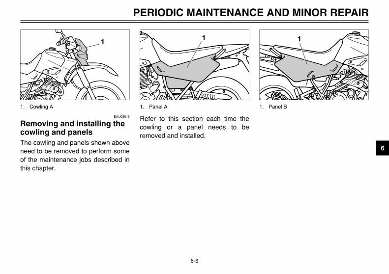
Removing and installing thecowling and panelsCowling and panels, removing and installing
The cowling and panels shown aboveneed to be removed to perform someof the maintenance jobs described inthis chapter.
1
1. Cowling A
1
1. Panel B
Refer to this section each time thecowling or a panel needs to beremoved and installed.
1
1. Panel A
4PT-E7 (English) 6/29/01 9:13 AM Page 43
6-7
PERIODIC MAINTENANCE AND MINOR REPAIR
6
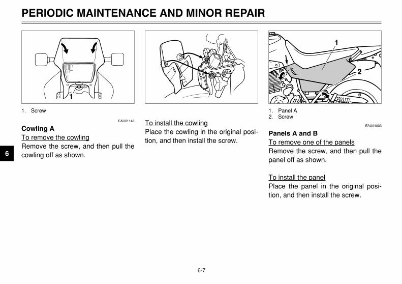
EAU01145
Cowling ATo remove the cowlingRemove the screw, and then pull thecowling off as shown.
1
1. Screw
EAU04003
Panels A and BTo remove one of the panelsRemove the screw, and then pull thepanel off as shown.
To install the panelPlace the panel in the original posi-tion, and then install the screw.
1
2
1. Panel A2. Screw
To install the cowlingPlace the cowling in the original posi-tion, and then install the screw.
4PT-E7 (English) 6/29/01 9:13 AM Page 44

6-8
PERIODIC MAINTENANCE AND MINOR REPAIR
6
1
2
1. Panel B2. Screw
2. Remove the spark plug asshown, with the spark plugwrench included in the owner’stool kit.
1
1. Spark plug wrench
EAU01833
Checking the spark plugSpark plug, checking
The spark plug is an importantengine component, which is easy tocheck. Since heat and deposits willcause any spark plug to slowly erode,the spark plug should be removedand checked in accordance with theperiodic maintenance and lubricationchart. In addition, the condition of thespark plug can reveal the condition ofthe engine.
To remove the spark plug1. Remove the spark plug cap.
1
1. Spark plug cap
4PT-E7 (English) 6/29/01 9:13 AM Page 45

6-9
PERIODIC MAINTENANCE AND MINOR REPAIR
6
To check the spark plug1. Check that the porcelain insula-
tor around the center electrodeof the spark plug is a medium-to-light tan (the ideal color when themotorcycle is ridden normally).
NOTE:If the spark plug shows a distinctlydifferent color, the engine could bedefective. Do not attempt to diagnosesuch problems yourself. Instead,have a Yamaha dealer check themotorcycle.
2. Check the spark plug for elec-trode erosion and excessive car-bon or other deposits, andreplace it if necessary.
3. Install the spark plug with thespark plug wrench, and thentighten it to the specified torque.
NOTE:If a torque wrench is not availablewhen installing a spark plug, a goodestimate of the correct torque is 1/4-1/2 turn past finger tight. However,the spark plug should be tightened tothe specified torque as soon as pos-sible.
4. Install the spark plug cap.
To install the spark plug1. Measure the spark plug gap with
a wire thickness gauge and, ifnecessary, adjust the gap tospecification.
2. Clean the surface of the sparkplug gasket and its mating sur-face, and then wipe off any grimefrom the spark plug threads.
a
a. Spark plug gap
Specified spark plug:DPR8EA-9 or DPR9EA-9 (NGK)
Spark plug gap:0.8–0.9 mm
Tightening torque:Spark plug:
17.5 Nm (1.75 m0kgf)
4PT-E7 (English) 6/29/01 9:13 AM Page 46

6-10
PERIODIC MAINTENANCE AND MINOR REPAIR
6
EAU04354
Engine oil and oil filter elementEngine oil and oil filter element
The engine oil level should bechecked before each ride. In addition,the oil must be changed and the oilfilter element replaced at the intervalsspecified in the periodic maintenanceand lubrication chart.
To check the engine oil level1. Place the motorcycle on a level
surface and hold it in an uprightposition.
NOTE:Make sure that the motorcycle ispositioned straight up when checkingthe oil level. A slight tilt to the sidecan result in a false reading.
4. Wait a few minutes until the oilsettles, remove the oil filler cap,wipe the dipstick clean, insert itback into the oil filler hole (with-out screwing it in), and thenremove it again to check the oillevel.
NOTE:The engine oil should be between theminimum and maximum level marks.
12
3
1. Oil filler cap2. Maximum level mark3. Minimum level mark
2. Remove the oil filler cap cover byremoving the screw.
3. Start the engine, warm it up forat least 10 seconds, and thenturn it off.
21
1. Screw2. Oil filler cap cover
4PT-E7 (English) 6/29/01 9:13 AM Page 47

6-11
PERIODIC MAINTENANCE AND MINOR REPAIR
6
EC000000
cC
Do not operate the motorcycleuntil you know that the engine oillevel is sufficient.
EW000065
w
Never remove the engine oil tankcap after high-speed operation,otherwise hot engine oil couldspout out and cause damage orinjury. Always let the engine oilcool down sufficiently beforeremoving the oil tank cap.
5. If the engine oil is below the min-imum level mark, add sufficientoil of the recommended type toraise it to the correct level.
6. Install the oil filler cap and the oilfiller cap cover.
4. Check the washers for damageand replace them if necessary.
NOTE:Skip steps 5–8 if the oil filter elementis not being replaced.
5. Remove the oil filter elementcover by removing the bolts.
NOTE:The oil filter element cover is securedby two bolts and a drain bolt. First,remove the drain bolt to drain the oilfilter element cavity.
1
3
2
1. Oil filter cover bolt (×2)2. Oil filter cover3. Oil filter drain bolt
To change the engine oil (with orwithout oil filter element replace-ment)
1. Start the engine, warm it up forseveral minutes, and then turn itoff.
2. Place an oil pan under theengine to collect the used oil.
3. Remove the oil filler cap cover,the oil filler cap and the drainbolts to drain the oil from thecrankcase and oil tank.
1. Drain bolt (oil tank)2. Drain bolt (crankcase)
1
2
4PT-E7 (English) 6/29/01 9:13 AM Page 48

6-12
PERIODIC MAINTENANCE AND MINOR REPAIR
6
6. Remove and replace the oil filterelement.
7. Check the O-rings for damageand replace them if necessary.
8. Install the oil filter element coverby installing the bolts, then tight-ening them to the specifiedtorque.
NOTE:Make sure that the O-ring is properlyseated.
9. Install the engine oil drain bolts,and then tighten them to thespecified torques.
10. Add the specified amount of therecommended engine oil, installand tighten the oil filler cap, andthen install the oil filler cap cover.
ECA00105
cC
8 In order to prevent clutch slip-page (since the engine oil alsolubricates the clutch), do notmix any chemical additiveswith the oil or use oils of grade“CD” or higher. In addition, donot use oils labeled “ENERGYCONSERVING II” or higher.
8 Make sure that no foreignmaterial enters the crankcase.
1
2
1. Oil filter element2. O-ring (×2)
Tightening torque:Oil filter element cover bolt:
10 Nm (1.0 m0kgf)
Tightening torques:Engine oil drain bolt (crankcase):
30 Nm (3.0 m0kgf)Engine oil drain bolt (oil tank):
18 Nm (1.8 m0kgf)Recommended engine oil:
See page 8-1.Oil quantity:
Without oil filter element replacement:
2.7 LWith oil filter element replacement:
2.8 LTotal amount (dry engine):
3.3 L
4PT-E7 (English) 6/29/01 9:13 AM Page 49

6-13
PERIODIC MAINTENANCE AND MINOR REPAIR
6
EC000076
cC
After changing the engine oil, besure to check the oil pressure asdescribed below.
11. Remove the air bleed screw, andthen start the engine. If oil doesnot seep out of the hole after afew minutes, immediately stopthe engine and have a Yamahadealer check for the cause. If oilseeps out of the hole, turn theengine off and install the airbleed screw.
12. Start the engine, and then let itidle for several minutes whilechecking it for oil leakage. If oil isleaking, immediately turn theengine off and check for thecause.
13. Turn the engine off, and thencheck the oil level and correct it ifnecessary.
1
1. Air bleed screw
EAU03514
Cleaning the air filter elementAir filter element, cleaning
The air filter element should becleaned at the intervals specified inthe periodic maintenance and lubrica-tion chart. Clean the air filter elementmore frequently if you are riding inunusually wet or dusty areas.
1. Remove panel B. (See page 6-8for panel removal and installationprocedures.)
2. Remove the air filter case coverby removing the screws, andthen pull the air filter elementout.
1
1
1. Screw (×7)
4PT-E7 (English) 6/29/01 9:13 AM Page 50

6-14
PERIODIC MAINTENANCE AND MINOR REPAIR
6
3. Lightly tap the air filter element toremove most of the dust and dirt,and then blow the remaining dirtout with compressed air asshown. If the air filter element isdamaged, replace it.
4. Insert the air filter element intothe air filter case with the arrowmark on the top pointing inward.
EAU00629
Adjusting the carburetorCarburetor, adjusting
The carburetor is an important part ofthe engine and requires very sophisti-cated adjustment. Therefore, mostcarburetor adjustments should be leftto a Yamaha dealer, who has thenecessary professional knowledgeand experience. The adjustmentdescribed in the following section,however, may be serviced by theowner as part of routine mainte-nance.
EC000094
cC
The carburetor has been set andextensively tested at the Yamahafactory. Changing these settingswithout sufficient technical knowl-edge may result in poor perfor-mance of or damage to the engine.
1
1. Mesh side
EC000082
cC
8 Make sure that the air filter ele-ment is properly seated in theair filter case.
8 The engine should never beoperated without the air filterelement installed, otherwisethe piston and/or cylinder maybecome excessively worn.
5. Install the air filter case cover byinstalling the screws.
6. Install the panel.
1
1. Arrow mark
4PT-E7 (English) 6/29/01 9:13 AM Page 51

6-15
PERIODIC MAINTENANCE AND MINOR REPAIR
6
EAU00632
Adjusting the engine idlingspeedEngine idling speed
The engine idling speed must bechecked and, if necessary, adjustedas follows at the intervals specified inthe periodic maintenance and lubrica-tion chart.
1. Start the engine and warm it upfor several minutes at 1,000–2,000 r/min while occasionallyrevving it to 4,000–5,000 r/min.
NOTE:The engine is warm when it quicklyresponds to the throttle.
NOTE:If the specified idling speed cannotbe obtained as described above,have a Yamaha dealer make theadjustment.
2. Check the engine idling speedand, if necessary, adjust it tospecification by turning the throt-tle stop screw. To increase theengine idling speed, turn thescrew in direction a. Todecrease the engine idlingspeed, turn the screw in directionb.
1
ba
1. Throttle stop screw
Engine idling speed:1,200–1,400 r/min(Except for CH)1,300–1,400 r/min(For CH)
4PT-E7 (English) 6/29/01 9:13 AM Page 52

6-16
PERIODIC MAINTENANCE AND MINOR REPAIR
6
EAU00635
Adjusting the throttle cablefree playThrottle cable free play, adjusting
The throttle cable free play shouldmeasure 3–5 mm at the throttle grip.Periodically check the throttle cablefree play and, if necessary, have aYamaha dealer adjust it.
a
a. Throttle cable free play
EAU04259
TiresTires
To maximize the performance, dura-bility, and safe operation of yourmotorcycle, note the following pointsregarding the specified tires.
Tire air pressureThe tire air pressure should bechecked and, if necessary, adjustedbefore each ride.
EW000082
w
8 The tire air pressure must bechecked and adjusted on coldtires (i.e., when the tempera-ture of the tires equals theambient temperature).
8 The tire air pressure must beadjusted in accordance withthe riding speed and with thetotal weight of rider, passen-ger, cargo, and accessoriesapproved for this model.
EAU00637
Adjusting the valve clearanceValve clearance, adjusting
The valve clearance changes withuse, resulting in improper air-fuel mix-ture and/or engine noise. To preventthis from occurring, the valve clear-ance must be adjusted by a Yamahadealer at the intervals specified in theperiodic maintenance and lubricationchart.
4PT-E7 (English) 6/29/01 9:13 AM Page 53

6-17
PERIODIC MAINTENANCE AND MINOR REPAIR
6
88 Adjust the suspension and tireair pressure with regard to theload.
8 Check the tire condition andair pressure before each ride.
EWA00012
w
Because loading has an enormousimpact on the handling, braking,performance and safety character-istics of your motorcycle, youshould keep the following precau-tions in mind.8 NEVER OVERLOAD THE
MOTORCYCLE! Operation ofan overloaded motorcycle mayresult in tire damage, loss ofcontrol, or severe injury. Makesure that the total weight ofrider, passenger, cargo, andaccessories does not exceedthe specified maximum loadfor the vehicle.
8 Do not carry along looselypacked items, which can shiftduring a ride.
8 Securely pack the heaviestitems close to the center of themotorcycle and distribute theweight evenly on both sides.
Tire air pressure(measured on cold tires)
Load* Front Rear
Up to 90 kg150 kPa
(1.50 kgf/cm2,1.50 bar)
150 kPa(1.50 kgf/cm2,
1.50 bar)
90 kg–maximum
150 kPa(1.50 kgf/cm2,
1.50 bar)
225 kPa(2.25 kgf/cm2,
2.25 bar)
Off-road riding125 kPa
(1.25 kgf/cm2,1.25 bar)
125 kPa(1.25 kgf/cm2,
1.25 bar)
High speed riding150 kPa
(1.50 kgf/cm2,1.50 bar)
225 kPa(2.25 kgf/cm2,
2.25 bar)
Maximum load*176 kg (XT500E)180 kg (XT600E)
* Total weight of rider, passenger, cargo andaccessories
4PT-E7 (English) 6/29/01 9:13 AM Page 54

6-18
PERIODIC MAINTENANCE AND MINOR REPAIR
6
Tire inspectionThe tires must be checked beforeeach ride. If the center tread depthreaches the specified limit, if the tirehas a nail or glass fragments in it, orif the sidewall is cracked, have aYamaha dealer replace the tire imme-diately.
a
1
1. Side walla. Tire tread depth
EW000078
w
8 The front and rear tires shouldbe of the same make anddesign, otherwise the handlingcharacteristics of the motorcy-cle cannot be guaranteed.
8 After extensive tests, only thetires listed below have beenapproved for this model byYamaha Motor Co., Ltd.
NOTE:The tire tread depth limits may differfrom country to country. Always com-ply with the local regulations.
Tire informationThis motorcycle is equipped with tubetires.
Minimum tire tread depth (front and rear)
1.6 mm
FRONT
Manufacturer Size Type
BRIDGESTONE90/90-21 54S
TW4790/90-21 M/C 54S
DUNLOP90/90-21 54S
TRAIL MAX L90/90-21 M/C 54S
REAR
Manufacturer Size Type
BRIDGESTONE120/90-17 64S
TW48120/90-17 M/C 64S
DUNLOP120/90-17 64S
TRAIL MAX120/90-17 M/C 64S
4PT-E7 (English) 6/29/01 9:13 AM Page 55

6-19
PERIODIC MAINTENANCE AND MINOR REPAIR
6
EAU00681
w
8 Have a Yamaha dealer replaceexcessively worn tires.Besides being illegal, operat-ing the motorcycle with exces-sively worn tires decreasesriding stability and can lead toloss of control.
8 The replacement of all wheel-and brake-related parts,including the tires, should beleft to a Yamaha dealer, whohas the necessary profession-al knowledge and experience.
8 It is not recommended topatch a punctured tube. Ifunavoidable, however, patchthe tube very carefully andreplace it as soon as possiblewith a high-quality product.
8 Ride at moderate speeds afterchanging a tire since the tire sur-face must first be “broken in” forit to develop its optimal charac-teristics.
EAU00685
Spoke wheelsWheels
To maximize the performance, dura-bility, and safe operation of yourmotorcycle, note the following pointsregarding the specified wheels.8 The wheel rims should be
checked for cracks, bends orwarpage, and the spokes forlooseness or damage beforeeach ride. If any damage isfound, have a Yamaha dealerreplace the wheel. Do notattempt even the smallest repairto the wheel. A deformed orcracked wheel must be replaced.
8 The wheel should be balancedwhenever either the tire or wheelhas been changed or replaced.An unbalanced wheel can resultin poor performance, adversehandling characteristics, and ashortened tire life.
4PT-E7 (English) 6/29/01 9:13 AM Page 56

6-20
PERIODIC MAINTENANCE AND MINOR REPAIR
6
EAU00694
Adjusting the clutch leverfree playClutch lever free play, adjusting
The clutch lever free play shouldmeasure 10–15 mm as shown.Periodically check the clutch leverfree play and, if necessary, adjust itas follows.
1. Loosen the locknut at the clutchlever.
2. To increase the clutch lever freeplay, turn the adjusting bolt indirection a. To decrease theclutch lever free play, turn theadjusting bolt in direction b.
a
b
1 2
c
1. Locknut (clutch lever)2. Adjusting boltc. Free play
7. Tighten the locknut at the clutchlever and the crankcase.
3. If the specified clutch lever freeplay could be obtained asdescribed above, tighten thelocknut and skip the rest of theprocedure, otherwise proceed asfollows.
4. Fully turn the adjusting bolt at theclutch lever in direction a toloosen the clutch cable.
5. Loosen the locknut at thecrankcase.
6. To increase the clutch lever freeplay, turn the adjusting nut indirection a. To decrease theclutch lever free play, turn theadjusting nut in direction b.
b
a
21
1. Locknut (crankcase)2. Adjusting nut
4PT-E7 (English) 6/29/01 9:13 AM Page 57

6-21
PERIODIC MAINTENANCE AND MINOR REPAIR
6
EAU00696
Adjusting the brake leverfree playBrake lever free play, adjusting
The brake lever free play shouldmeasure 2–5 mm as shown.Periodically check the brake leverfree play and, if necessary, adjust itas follows.
1. Loosen the locknut at the brakelever.
2. To increase the brake lever freeplay, turn the adjusting bolt indirection a. To decrease thebrake lever free play, turn theadjusting bolt in direction b.
1 2
b
a
c
1. Locknut2. Adjusting boltc. Free play EAU00712
Adjusting the brake pedalpositionBrake pedal position, adjusting
The top of the brake pedal should bepositioned approximately 12 mmbelow the top of the footrest asshown. Periodically check the brakepedal position and, if necessary,have a Yamaha dealer adjust it.
a
a. Brake pedal position
3. Tighten the locknut.EW000099
w
8 After adjusting the brake leverfree play, check the free playand make sure that the brakeis working properly.
8 A soft or spongy feeling in thebrake lever can indicate thepresence of air in thehydraulic system. If there is airin the hydraulic system, havea Yamaha dealer bleed thesystem before operating themotorcycle. Air in thehydraulic system will diminishthe braking performance,which may result in loss ofcontrol and an accident.
4PT-E7 (English) 6/29/01 9:13 AM Page 58

6-22
PERIODIC MAINTENANCE AND MINOR REPAIR
6
EW000109
w
A soft or spongy feeling in thebrake pedal can indicate the pres-ence of air in the hydraulic system.If there is air in the hydraulic sys-tem, have a Yamaha dealer bleedthe system before operating themotorcycle. Air in the hydraulicsystem will diminish the brakingperformance, which may result inloss of control and an accident.
EAU00721
Checking the front and rearbrake padsFront and rear brake pads, checking
The front and rear brake pads mustbe checked for wear at the intervalsspecified in the periodic maintenanceand lubrication chart.
EAU00713
Adjusting the rear brake lightswitchRear brake light switch, adjusting
The rear brake light switch, which isactivated by the brake pedal, is prop-erly adjusted when the brake lightcomes on just before braking takeseffect. If necessary, adjust the brakelight switch as follows.Turn the adjusting nut while holdingthe rear brake light switch in place.To make the brake light come on ear-lier, turn the adjusting nut in directiona. To make the brake light come onlater, turn the adjusting nut in direc-tion b.
2
1
ab
1. Rear brake light switch2. Adjusting nut
4PT-E7 (English) 6/29/01 9:13 AM Page 59
6-23
PERIODIC MAINTENANCE AND MINOR REPAIR
6
EAU03938
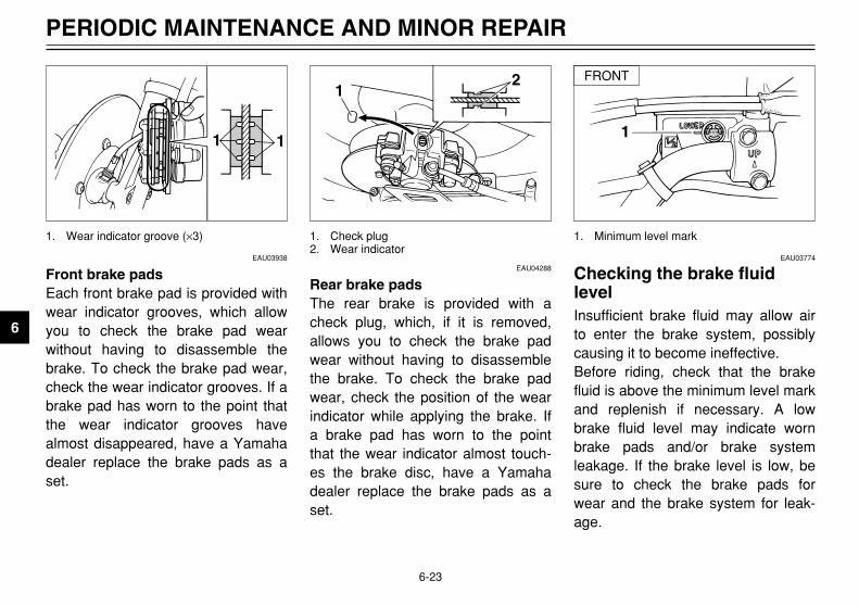
Front brake padsEach front brake pad is provided withwear indicator grooves, which allowyou to check the brake pad wearwithout having to disassemble thebrake. To check the brake pad wear,check the wear indicator grooves. If abrake pad has worn to the point thatthe wear indicator grooves havealmost disappeared, have a Yamahadealer replace the brake pads as aset.
1 1
1. Wear indicator groove (×3)
EAU03774
Checking the brake fluidlevelBrake fluid level, checking
Insufficient brake fluid may allow airto enter the brake system, possiblycausing it to become ineffective.Before riding, check that the brakefluid is above the minimum level markand replenish if necessary. A lowbrake fluid level may indicate wornbrake pads and/or brake systemleakage. If the brake level is low, besure to check the brake pads forwear and the brake system for leak-age.
1
1. Minimum level mark
EAU04288
Rear brake padsThe rear brake is provided with acheck plug, which, if it is removed,allows you to check the brake padwear without having to disassemblethe brake. To check the brake padwear, check the position of the wearindicator while applying the brake. Ifa brake pad has worn to the pointthat the wear indicator almost touch-es the brake disc, have a Yamahadealer replace the brake pads as aset.
12
1. Check plug2. Wear indicator
FRONT
4PT-E7 (English) 6/29/01 9:13 AM Page 60

6-24
PERIODIC MAINTENANCE AND MINOR REPAIR
6
Observe these precautions:8 When checking the fluid level,
make sure that the top of thebrake fluid reservoir is level.
8 Use only the recommended qual-ity brake fluid, otherwise the rub-ber seals may deteriorate, caus-ing leakage and poor brakingperformance.
8 Refill with the same type of brakefluid. Mixing fluids may result in aharmful chemical reaction andlead to poor braking perfor-mance.
8 Be careful that water does notenter the brake fluid reservoirwhen refilling. Water will signifi-cantly lower the boiling point ofthe fluid and may result in vaporlock.
8 Brake fluid may deteriorate paint-ed surfaces or plastic parts.Always clean up spilled fluidimmediately.
8 As the brake pads wear, it is nor-mal for the brake fluid level togradually go down. However, ifthe brake fluid level goes downsuddenly, have a Yamaha dealercheck the cause.
EAU03976
Changing the brake fluidBrake fluid, changing
Have a Yamaha dealer change thebrake fluid at the intervals specified inthe NOTE after the periodic mainte-nance and lubrication chart. In addi-tion, have the oil seals of the mastercylinders and calipers as well as thebrake hoses replaced at the intervalslisted below or whenever they aredamaged or leaking.8 Oil seals: Replace every two
years.8 Brake hoses: Replace every four
years.
1
1. Minimum level mark
REAR
Recommended brake fluid: DOT 4
4PT-E7 (English) 6/29/01 9:13 AM Page 61

6-25
PERIODIC MAINTENANCE AND MINOR REPAIR
6
EAU00744
Drive chain slackDrive chain slack
The drive chain slack should bechecked before each ride and adjust-ed if necessary.
To check the drive chain slackChecking
1. Place the motorcycle on a levelsurface and hold it in an uprightposition.
NOTE:When checking and adjusting thedrive chain slack, the motorcycleshould be positioned straight up andthere should be no weight on it.
2. Shift the transmission into theneutral position.
EAU01134
To adjust the drive chain slackadjusting
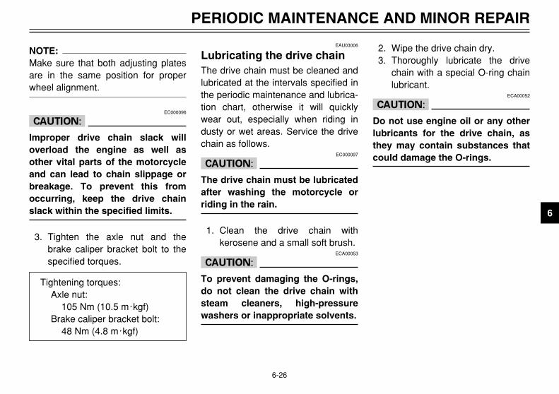
1. Loosen the axle nut and thebrake caliper bracket bolt.
2. To tighten the drive chain, turnthe adjusting plate on each sideof the swingarm in direction a.To loosen the drive chain, turnthe adjusting plate on each sideof the swingarm in direction b,and then push the rear wheel for-ward.
a
b2
1
3
1. Adjusting plate2. Axle nut3. Brake caliper bracket bolt3. Move the rear wheel by pushing
the motorcycle to locate the tight-est portion of the drive chain,and then measure the drivechain slack as shown.
4. If the drive chain slack is incor-rect, adjust it as follows.
a
a. Drive chain slack
Drive chain slack:30–40 mm
4PT-E7 (English) 6/29/01 9:13 AM Page 62
6-26
PERIODIC MAINTENANCE AND MINOR REPAIR
6
NOTE:Make sure that both adjusting platesare in the same position for properwheel alignment.
EC000096
cC
Improper drive chain slack willoverload the engine as well asother vital parts of the motorcycleand can lead to chain slippage orbreakage. To prevent this fromoccurring, keep the drive chainslack within the specified limits.
3. Tighten the axle nut and thebrake caliper bracket bolt to thespecified torques.
2. Wipe the drive chain dry.3. Thoroughly lubricate the drive
chain with a special O-ring chainlubricant.
ECA00052
cC
Do not use engine oil or any otherlubricants for the drive chain, asthey may contain substances thatcould damage the O-rings.
EAU03006
Lubricating the drive chainDrive chain, lubricating
The drive chain must be cleaned andlubricated at the intervals specified inthe periodic maintenance and lubrica-tion chart, otherwise it will quicklywear out, especially when riding industy or wet areas. Service the drivechain as follows.
EC000097
cC
The drive chain must be lubricatedafter washing the motorcycle orriding in the rain.
1. Clean the drive chain withkerosene and a small soft brush.
ECA00053
cC
To prevent damaging the O-rings,do not clean the drive chain withsteam cleaners, high-pressurewashers or inappropriate solvents.
Tightening torques:Axle nut:
105 Nm (10.5 m0kgf)Brake caliper bracket bolt:
48 Nm (4.8 m0kgf)
4PT-E7 (English) 6/29/01 9:13 AM Page 63
6-27
PERIODIC MAINTENANCE AND MINOR REPAIR
6
EAU02962
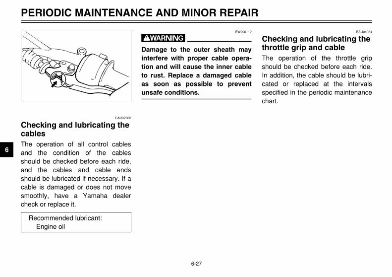
Checking and lubricating thecablesCables, checking and lubricating
The operation of all control cablesand the condition of the cablesshould be checked before each ride,and the cables and cable endsshould be lubricated if necessary. If acable is damaged or does not movesmoothly, have a Yamaha dealercheck or replace it.
EAU04034
Checking and lubricating thethrottle grip and cableThrottle grip and cable, checking and lubricating
The operation of the throttle gripshould be checked before each ride.In addition, the cable should be lubri-cated or replaced at the intervalsspecified in the periodic maintenancechart.
EW000112
w
Damage to the outer sheath mayinterfere with proper cable opera-tion and will cause the inner cableto rust. Replace a damaged cableas soon as possible to preventunsafe conditions.
Recommended lubricant:Engine oil
4PT-E7 (English) 6/29/01 9:13 AM Page 64

6-28
PERIODIC MAINTENANCE AND MINOR REPAIR
6
EAU03370
Checking and lubricating thebrake and shift pedalsBrake and shift pedals, checking and lubricating
The operation of the brake and shiftpedals should be checked beforeeach ride, and the pedal pivotsshould be lubricated if necessary.
EAU03164
Checking and lubricating thebrake and clutch leversBrake and clutch levers, checking and lubricating
The operation of the brake and clutchlevers should be checked beforeeach ride, and the lever pivots shouldbe lubricated if necessary.
EAU03165
Checking and lubricating thesidestandSidestand, checking and lubricating
The operation of the sidestandshould be checked before each ride,and the sidestand pivot and metal-to-metal contact surfaces should belubricated if necessary.
EW000113
w
If the sidestand does not move upand down smoothly, have aYamaha dealer check or repair it.
Recommended lubricant:Lithium-soap-based grease (all-purpose grease)
Recommended lubricant:Lithium-soap-based grease (all-purpose grease)
Recommended lubricant:Lithium-soap-based grease (all-purpose grease)
4PT-E7 (English) 6/29/01 9:13 AM Page 65

6-29
PERIODIC MAINTENANCE AND MINOR REPAIR
6
EAU00790
Lubricating the rear suspensionRear suspension, lubricating
The pivoting points of the rear sus-pension must be lubricated at theintervals specified in the periodicmaintenance and lubrication chart.
1
1
1. Grease nipple (×2)
To check the operation1. Place the motorcycle on a level
surface and hold it in an uprightposition.
2. While applying the front brake,push down hard on the handle-bars several times to check if thefront fork compresses andrebounds smoothly.
EC000098
cC
If any damage is found or the frontfork does not operate smoothly,have a Yamaha dealer check orrepair it.
EAU02939
Checking the front forkFront fork, checking
The condition and operation of thefront fork must be checked as followsat the intervals specified in the peri-odic maintenance and lubricationchart.
To check the conditionEW000115
w
Securely support the motorcycleso that there is no danger of itfalling over.
Check the inner tubes for scratches,damage and excessive oil leakage.
Recommended lubricant:Molybdenum disulfide grease
4PT-E7 (English) 6/29/01 9:13 AM Page 66

6-30
PERIODIC MAINTENANCE AND MINOR REPAIR
6
EAU00794
Checking the steeringSteering, checking
Worn or loose steering bearings maycause danger. Therefore, the opera-tion of the steering must be checkedas follows at the intervals specified inthe periodic maintenance and lubrica-tion chart.
1. Place a stand under the engineto raise the front wheel off theground.
EW000115
w
Securely support the motorcycleso that there is no danger of itfalling over.
EAU01144
Checking the wheel bearingsWheel bearings, checking
The front and rear wheel bearingsmust be checked at the intervalsspecified in the periodic maintenanceand lubrication chart. If there is playin the wheel hub or if the wheel doesnot turn smoothly, have a Yamahadealer check the wheel bearings.
2. Hold the lower ends of the frontfork legs and try to move themforward and backward. If anyfree play can be felt, have aYamaha dealer check or repairthe steering.
4PT-E7 (English) 6/29/01 9:13 AM Page 67

6-31
PERIODIC MAINTENANCE AND MINOR REPAIR
6
EAU00800
BatteryBattery
This motorcycle is equipped with asealed-type (MF) battery, which doesnot require any maintenance. Thereis no need to check the electrolyte orto add distilled water.
EC000101
cC
Never attempt to remove the bat-tery cell seals, as this would per-manently damage the battery.
88 KEEP THIS AND ALL BATTER-IES OUT OF THE REACH OFCHILDREN.
EW000116
w
88 Electrolyte is poisonous anddangerous since it containssulfuric acid, which causessevere burns. Avoid any con-tact with skin, eyes or clothingand always shield your eyeswhen working near batteries.In case of contact, administerthe following FIRST AID.99 EXTERNAL: Flush with plen-
ty of water.99 INTERNAL: Drink large quan-
tities of water or milk andimmediately call a physician.
99 EYES: Flush with water for15 minutes and seek promptmedical attention.
88 Batteries produce explosivehydrogen gas. Therefore, keepsparks, flames, cigarettes,etc., away from the battery andprovide sufficient ventilationwhen charging it in anenclosed space.
4PT-E7 (English) 6/29/01 9:13 AM Page 68

6-32
PERIODIC MAINTENANCE AND MINOR REPAIR
6
To charge the batteryHave a Yamaha dealer charge thebattery as soon as possible if itseems to have discharged. Keep inmind that the battery tends to dis-charge more quickly if the motorcycleis equipped with optional electricalaccessories.
To store the battery1. If the motorcycle will not be used
for more than one month,remove the battery, fully chargeit, and then place it in a cool, dryplace.
2. If the battery will be stored formore than two months, check itat least once a month and fullycharge it if necessary.
3. Fully charge the battery beforeinstallation.
4. After installation, make sure thatthe battery leads are properlyconnected to the battery termi-nals.
EAU01307
Replacing the fuseFuse, replacing
The fuse holder is located behindpanel A. (See page 6-7 for panelremoval and installation procedures.)If the fuse is blown, replace it as fol-lows.
1. Turn the key to “OFF” and turnoff all electrical circuits.
2. Remove the blown fuse, andthen install a new fuse of thespecified amperage.
1
2
1. Fuse2. Spare fuse
EC000102
cC
88 Always keep the batterycharged. Storing a dischargedbattery can cause permanentbattery damage.
88 To charge a sealed-type (MF)battery, a special (constant-voltage) battery charger isrequired. Using a conventionalbattery charger will damagethe battery. If you do not haveaccess to a sealed-type (MF)battery charger, have aYamaha dealer charge yourbattery.
Specified fuse:20 A
4PT-E7 (English) 6/29/01 9:13 AM Page 69
6-33
PERIODIC MAINTENANCE AND MINOR REPAIR
6
EC000103
cC
Do not use a fuse of a higheramperage rating than recommend-ed to avoid causing extensivedamage to the electrical systemand possibly a fire.
3. Turn the key to “ON” and turn onthe electrical circuits to check ifthe devices operate.
4. If the fuse immediately blowsagain, have a Yamaha dealercheck the electrical system.
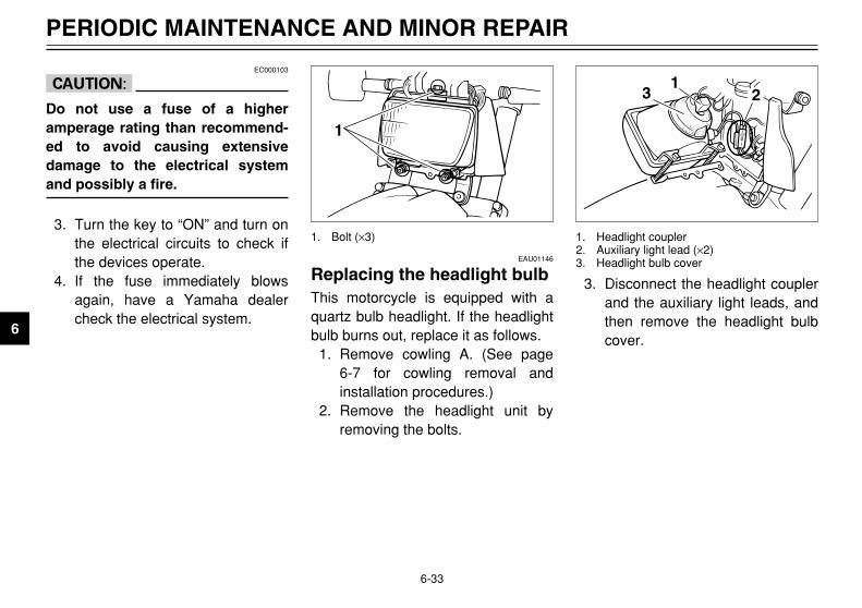
3. Disconnect the headlight couplerand the auxiliary light leads, andthen remove the headlight bulbcover.
31
2
1. Headlight coupler2. Auxiliary light lead (×2)3. Headlight bulb coverEAU01146
Replacing the headlight bulbHeadlight bulb, replacing
This motorcycle is equipped with aquartz bulb headlight. If the headlightbulb burns out, replace it as follows.
1. Remove cowling A. (See page 6-7 for cowling removal andinstallation procedures.)
2. Remove the headlight unit byremoving the bolts.
1
1. Bolt (×3)
4PT-E7 (English) 6/29/01 9:13 AM Page 70

6-34
PERIODIC MAINTENANCE AND MINOR REPAIR
6
4. Remove the headlight bulb hold-er by turning it counterclockwise,and then remove the defectivebulb.
EW000119
w
Headlight bulbs get very hot.Therefore, keep flammable prod-ucts away from a lit headlight bulb,and do not touch the bulb until ithas cooled down.
1
1. Headlight bulb holder
6. Install the bulb cover, and thenconnect the coupler and leads.
7. Install the headlight unit byinstalling the bolts.
8. Install the cowling.9. Have a Yamaha dealer adjust
the headlight beam if necessary.
5. Place a new bulb into position,and then secure it with the bulbholder.
EC000105
cC
Do not touch the glass part of theheadlight bulb to keep it free fromoil, otherwise the transparency ofthe glass, the luminosity of thebulb, and the bulb life will beadversely affected. Thoroughlyclean off any dirt and fingerprintson the headlight bulb using a clothmoistened with alcohol or thinner.
a
a. Do not touch this area.
4PT-E7 (English) 6/29/01 9:13 AM Page 71

6-35
PERIODIC MAINTENANCE AND MINOR REPAIR
6
EAU03497
Replacing a turn signal lightbulbTurn signal light bulb, replacing
1. Remove the turn signal light lensby removing the screw.
1
2
1. Screw2. Lens
EAU01623
Replacing the tail/brake lightbulbTail/brake light bulb, replacing
1. Remove the tail/brake light lensby removing the screws.
2
1
1. Screw (×2)2. Lens
2. Remove the defective bulb bypushing it in and turning it coun-terclockwise.
3. Insert a new bulb into the socket,push it in, and then turn it clock-wise until it stops.
4. Install the lens by installing thescrew.
ECA00065
cC
Do not overtighten the screw, oth-erwise the lens may break.
1
1. Bulb
4PT-E7 (English) 6/29/01 9:13 AM Page 72

6-36
PERIODIC MAINTENANCE AND MINOR REPAIR
6
2. Remove the defective bulb bypushing it in and turning it coun-terclockwise.
3. Insert a new bulb into the socket,push it in, and then turn it clock-wise until it stops.
4. Install the lens by installing thescrews.
EC000108
cC
Do not overtighten the screws,otherwise the lens may break.
1
1. Bulb
To service the rear wheelRaise the rear wheel off the groundby using a motorcycle stand or, if amotorcycle stand is not available, byplacing a jack either under each sideof the frame in front of the rear wheelor under each side of the swingarm.
EAU01579
Supporting the motorcycleSupporting the motorcycle
Since this model is not equipped witha centerstand, follow these precau-tions when removing the front andrear wheel or performing other main-tenance requiring the motorcycle tostand upright. Check that the motor-cycle is in a stable and level positionbefore starting any maintenance. Astrong wooden box can be placedunder the engine for added stability.
To service the front wheel1. Stabilize the rear of the motorcy-
cle by using a motorcycle standor, if an additional motorcyclestand is not available, by placinga jack under the frame in front ofthe rear wheel.
2. Raise the front wheel off theground by using a motorcyclestand.
4PT-E7 (English) 6/29/01 9:13 AM Page 73

6-37
PERIODIC MAINTENANCE AND MINOR REPAIR
6
EAU00897
Front wheel Removing
To remove the front wheelEW000122
w
8 It is advisable to have aYamaha dealer service thewheel.
8 Securely support the motorcy-cle so that there is no dangerof it falling over.
1. Disconnect the speedometercable from the front wheel.
1
1. Speedometer cable
EAU03555
To install the front wheelInstalling
1. Install the speedometer gear unitinto the wheel hub so that theprojections mesh with the slots.
2. Lift the wheel up between thefork legs.
1
1. Speedometer gear unit
2. Loosen the wheel axle holdernuts, then the wheel axle.
3. Lift the front wheel off the groundaccording to the procedure onpage 6-36.
4. Pull the wheel axle out, and thenremove the wheel.
ECA00048
cC
Do not apply the brake after thewheel has been removed togetherwith the brake disc, otherwise thebrake pads will be forced shut.
1
2
1. Wheel axle holder nut (×4)2. Wheel axle
4PT-E7 (English) 6/29/01 9:13 AM Page 74

6-38
PERIODIC MAINTENANCE AND MINOR REPAIR
6
NOTE:Make sure that there is enoughspace between the brake padsbefore inserting the brake disc andthat the slot in the speedometer gearunit fits over the retainer on the forkleg.
3. Install the wheel axle.4. Lower the front wheel so that it is
on the ground.5. Tighten the wheel axle to the
specified torque.
7. After tightening the holder nuts,while applying the front brake,push down on the handlebarsseveral times to check if the frontfork compresses and reboundssmoothly.
8. Connect the speedometer cable.1
1. Retainer
6. Tighten the axle holder nuts tothe specified tightening torque.Tighten the upper nuts first andthen lower ones. When tightenedin this sequence, there should bea gap formed at the bottom ofthe axle holder.
2
1
a
1. Upper nut (×2)2. Lower nut (×2)a. Gap
Tightening torque:Wheel axle:
59 Nm (5.9 m0kgf)
Tightening torque:Axle holder nut:
9 Nm (0.9 m0kgf)
4PT-E7 (English) 6/29/01 9:13 AM Page 75

6-39
PERIODIC MAINTENANCE AND MINOR REPAIR
6
EAU04314
Rear wheel
To remove the rear wheelEW000122
w
88 It is advisable to have aYamaha dealer service thewheel.
8 Securely support the motorcy-cle so that there is no dangerof it falling over.
1. Remove the axle nut.2. Loosen the brake caliper bracket
bolt.
21
1. Axle nut2. Brake caliper bracket bolt
5. Turn the drive chain adjustingplate on each side of theswingarm fully in direction a.
1
a
1. Chain adjusting plate
3. Lift the rear wheel off the groundaccording to the procedure onpage 6-36.
4. Remove the swingarm end bolts.
11
1. Swingarm end bolt (×2)
4PT-E7 (English) 6/29/01 9:13 AM Page 76

6-40
PERIODIC MAINTENANCE AND MINOR REPAIR
6
6. Push the wheel forward, andthen remove the drive chain fromthe rear sprocket.
NOTE:The drive chain does not need to bedisassembled in order to remove andinstall the wheel.
7. Pull the wheel axle out, and thenremove the wheel.
ECA00048
cC
Do not apply the brake after thewheel has been removed togetherwith the brake disc, otherwise thebrake pads will be forced shut.
EAU01136
To install the rear wheelInstall
1. Install the drive chain onto therear sprocket, and then insert thewheel axle from the left-handside.
NOTE:8 Make sure that there is enough
space between the brake padsbefore inserting the brake discbetween the brake pads.
8 Make sure that the drive chainadjusting plates are installed withthe punched sides facing to theoutside.
2. Install the swingarm end bolts.3. Adjust the drive chain slack.
(See page 6-25 for drive chainslack adjustment procedures.)
4. Tighten the axle nut, brakecaliper bracket bolt andswingarm end bolts to the speci-fied torques.
4PT-E7 (English) 6/29/01 9:13 AM Page 77

6-41
PERIODIC MAINTENANCE AND MINOR REPAIR
6
EAU01008
TroubleshootingTroubleshooting
Although Yamaha motorcyclesreceive a thorough inspection beforeshipment from the factory, troublemay occur during operation. Anyproblem in the fuel, compression, orignition systems, for example, cancause poor starting and loss ofpower.The following troubleshooting chartrepresents a quick and easy proce-dure for checking these vital systemsyourself. However, should yourmotorcycle require any repair, take itto a Yamaha dealer, whose skilledtechnicians have the necessary tools,experience, and know-how to servicethe motorcycle properly.Use only genuine Yamaha replace-ment parts. Imitation parts may looklike Yamaha parts, but they are ofteninferior, have a shorter service lifeand can lead to expensive repairbills.
Tightening torque:Axle nut:
105 Nm (10.5 m0kgf)Brake caliper bracket bolt:
48 Nm (4.8 m0kgf)Swingarm end bolt:
2.5 Nm (0.25 m0kgf)
4PT-E7 (English) 6/29/01 9:13 AM Page 78

6-42
PERIODIC MAINTENANCE AND MINOR REPAIR
6
1. Fuel
2. Compression
3. Ignition
4. Battery
Use electric starter.
There is compression. Go to ignition check.
No compression. Ask a Yamaha dealer to inspect.
Wet.
Dry.
Wipe clean with dry cloth and
Ask a Yamaha dealer to inspect.
Check if there is fuel
Enough fuel
No fuel
Go to compression check.
Supply fuel.
in the fuel tank.
Remove spark
electrodes.plug and check
Open throttle half-way and start the
Engine doesn’t start, go to batterycheck.
engine.correct spark gap or replace spark plug.
Engine turns over
Engine turns over
Battery good.
Check connections
quickly.
slowly. or recharge.
Engine doesn’t start, ask a Yamahadealer to inspect.
Engine doesn’t start, go to compression check.
Use the electricstarter.
EAU01397
Troubleshooting chartTroubleshooting chart
EW000125
w
Keep away open flames and do not smoke while checking or working on the fuel system.
4PT-E7 (English) 6/29/01 9:13 AM Page 79

4PT-E7 (English) 6/29/01 9:13 AM Page 80

MOTORCYCLE CARE AND STORAGE
Care .................................................................................................. 7-1Storage ............................................................................................. 7-4
7
4PT-E7 (English) 6/29/01 9:13 AM Page 81

7-1
EAU03521
MOTORCYCLE CARE AND STORAGE
7
CareCare
While the open design of a motorcy-cle reveals the attractiveness of thetechnology, it also makes it more vul-nerable. Rust and corrosion candevelop even if high-quality compo-nents are used. A rusty exhaust pipemay go unnoticed on a car, however,it detracts from the overall appear-ance of a motorcycle. Frequent andproper care does not only complywith the terms of the warranty, but itwill also keep your motorcycle lookinggood, extend its life and optimize itsperformance.
Before cleaning1. Cover the muffler outlet with a
plastic bag after the engine hascooled down.
2. Make sure that all caps and cov-ers as well as all electrical cou-plers and connectors, includingthe spark plug cap, are tightlyinstalled.
3. Remove extremely stubborn dirt,like oil burnt onto the crankcase,with a degreasing agent and abrush, but never apply suchproducts onto seals, gaskets,sprockets, the drive chain andwheel axles. Always rinse the dirtand degreaser off with water.
CleaningECA00010
cC
88 Avoid using strong acidicwheel cleaners, especially onspoked wheels. If such prod-ucts are used on hard-to-remove dirt, do not leave thecleaner on the affected areaany longer than instructed.Also, thoroughly rinse the areaoff with water, immediately dryit, and then apply a corrosionprotection spray.
88 Improper cleaning can damagewindshields, cowlings, panelsand other plastic parts. Useonly a soft, clean cloth orsponge with mild detergentand water to clean plastic.
4PT-E7 (English) 6/29/01 9:13 AM Page 82

7-2
MOTORCYCLE CARE AND STORAGE
7
88 Do not use any harsh chemicalproducts on plastic parts. Besure to avoid using cloths orsponges which have been incontact with strong or abra-sive cleaning products, sol-vent or thinner, fuel (gasoline),rust removers or inhibitors,brake fluid, antifreeze or elec-trolyte.
88 Do not use high-pressurewashers or steam-jet cleanerssince they cause water seep-age and deterioration in thefollowing areas: seals (ofwheel and swingarm bearings,fork and brakes), electric com-ponents (couplers, connec-tors, instruments, switchesand lights), breather hosesand vents.
88 For motorcycles equippedwith a windshield: Do not usestrong cleaners or hardsponges as they will causedulling or scratching. Somecleaning compounds for plas-tic may leave scratches on thewindshield. Test the producton a small hidden part of thewindshield to make sure that itdoes not leave any marks. Ifthe windshield is scratched,use a quality plastic polishingcompound after washing.
After normal useRemove dirt with warm water, a milddetergent, and a soft, clean sponge,and then rinse thoroughly with cleanwater. Use a toothbrush or bottle-brush for hard-to-reach areas.Stubborn dirt and insects will comeoff more easily if the area is coveredwith a wet cloth for a few minutesbefore cleaning.
After riding in the rain, near the seaor on salt-sprayed roadsSince sea salt or salt sprayed onroads during winter are extremelycorrosive in combination with water,carry out the following steps aftereach ride in the rain, near the sea oron salt-sprayed roads.
NOTE:Salt sprayed on roads in the wintermay remain well into spring.
1. Clean the motorcycle with coldwater and a mild detergent, afterthe engine has cooled down.
ECA00012
cC
Do not use warm water since itincreases the corrosive action ofthe salt.
2. Apply a corrosion protectionspray on all metal, includingchrome- and nickel-plated, sur-faces to prevent corrosion.
4PT-E7 (English) 6/29/01 9:13 AM Page 83

7-3
MOTORCYCLE CARE AND STORAGE
7
After cleaning1. Dry the motorcycle with a
chamois or an absorbing cloth.2. Immediately dry the drive chain
and lubricate it to prevent it fromrusting.
3. Use a chrome polish to shinechrome, aluminum and stainless-steel parts, including the exhaustsystem. (Even the thermallyinduced discoloring of stainless-steel exhaust systems can beremoved through polishing.)
4. To prevent corrosion, it is recom-mended to apply a corrosion pro-tection spray on all metal, includ-ing chrome- and nickel-plated,surfaces.
5. Use spray oil as a universalcleaner to remove any remainingdirt.
6. Touch up minor paint damagecaused by stones, etc.
7. Wax all painted surfaces.
8. Let the motorcycle dry complete-ly before storing or covering it.
EWA00001
w
8 Make sure that there is no oilor wax on the brakes or tires.If necessary, clean the brakediscs and brake linings with aregular brake disc cleaner oracetone, and wash the tireswith warm water and a milddetergent.
8 Before operating the motorcy-cle test its braking perfor-mance and cornering behav-ior.
ECA00013
cC
8 Apply spray oil and wax spar-ingly and make sure to wipeoff any excess.
8 Never apply oil or wax to anyrubber and plastic parts, buttreat them with a suitable careproduct.
8 Avoid using abrasive polish-ing compounds as they willwear away the paint.
NOTE:Consult a Yamaha dealer for adviceon what products to use.
4PT-E7 (English) 6/29/01 9:13 AM Page 84
7-4
MOTORCYCLE CARE AND STORAGE
7
StorageStorage
Short-termAlways store your motorcycle in acool, dry place and, if necessary, pro-tect it against dust with a porouscover.
ECA00014
cC
8 Storing the motorcycle in apoorly ventilated room or cov-ering it with a tarp, while it isstill wet, will allow water andhumidity to seep in and causerust.
8 To prevent corrosion, avoiddamp cellars, stables (becauseof the presence of ammonia)and areas where strong chemi-cals are stored.
Long-termBefore storing your motorcycle forseveral months:
1. Follow all the instructions in the“Care” section of this chapter.
2. For motorcycles equipped with afuel cock that has an “OFF” posi-tion: Turn the fuel cock lever to“OFF”.
3. Drain the carburetor float cham-ber by loosening the drain bolt;this will prevent fuel depositsfrom building up. Pour thedrained fuel into the fuel tank.
4. Fill up the fuel tank and add fuelstabilizer (if available) to preventthe fuel tank from rusting and thefuel from deteriorating.
5. Perform the following steps toprotect the cylinder, piston rings,etc. from corrosion.a. Remove the spark plug cap
and spark plug.b. Pour a teaspoonful of engine
oil into the spark plug bore.
c. Install the spark plug cap ontothe spark plug, and then placethe spark plug on the cylinderhead so that the electrodesare grounded. (This will limitsparking during the next step.)
d. Turn the engine over severaltimes with the starter. (Thiswill coat the cylinder wall withoil.)
e. Remove the spark plug capfrom the spark plug, and theninstall the spark plug and thespark plug cap.
EWA00003
w
To prevent damage or injury fromsparking, make sure to ground thespark plug electrodes while turn-ing the engine over.
4PT-E7 (English) 6/29/01 9:13 AM Page 85

7-5
MOTORCYCLE CARE AND STORAGE
7
6. Lubricate all control cables andthe pivoting points of all leversand pedals as well as of thesidestand/centerstand.
7. Check and, if necessary, correctthe tire air pressure, and then liftthe motorcycle so that both of itswheels are off the ground.Alternatively, turn the wheels alittle every month in order to pre-vent the tires from becomingdegraded in one spot.
8. Cover the muffler outlet with aplastic bag to prevent moisturefrom entering it.
9. Remove the battery and fullycharge it. Store it in a cool, dryplace and charge it once amonth. Do not store the batteryin an excessively cold or warmplace (less than 0 °C) or morethan 30 °C). For more informa-tion on storing the battery, seepage 6-32.
NOTE:Make any necessary repairs beforestoring the motorcycle.
4PT-E7 (English) 6/29/01 9:13 AM Page 86

SPECIFICATIONS
Specifications ................................................................................... 8-1Conversion table ............................................................................... 8-5
8
4PT-E7 (English) 6/29/01 9:13 AM Page 87

8-1
EAU01038
SPECIFICATIONS
8
SpecificationsSpecifications
Model XT500E/XT600E
Dimensions
Overall length 2,220 mm 2.295 mm (N, S, CH only)
Overall width 865 mm825 mm (CH only)
Overall height 1,205 mm
Seat height 855 mm
Wheel base 1,440 mm
Ground clearance 230 mm
Minimum turning radius 2,300 mm
Basic weight (with oil and fullfuel tank) 176 kg
172 kg (CH only)Engine
Engine type Air-cooled 4-stroke, SOHC,gasoline
Cylinder arrangement Forward inclined singlecylinder
Displacement 499 cm3
595 cm3
Bore × Stroke 87.0 × 84.0 mm (XT500E)95.0 × 84.0 mm (XT600E)
Compression ratio 8.5:1
Starting system Electric starter
Lubrication system Dry sump
Engine oil
Type
Recommended engine oilclassification API Service SE, SF, SG type
or higher
cCBe sure to use motor oils that do not contain anti-frictionmodifiers. Passenger car motor oils (often labeled “ENERGY CONSERVING II”) contain anti-friction additiveswhich will cause clutch and/or starter clutch slippage, result-ing in reduced component life and poor engine performance.
Capacity
Without oil filter elementreplacement 2.7 L
With oil filter elementreplaced 2.8 L
Total amount (dry engine) 3.3 L
–10° 0° 10° 20° 30° 40°
SAE 10W/30
SAE 10W/40
SAE 20W/40
SAE 20W/50
–20°
SAE 15W/40
50°C
4PT-E7 (English) 6/29/01 9:13 AM Page 88

8-2
SPECIFICATIONS
8
Air filter Dry type element
Fuel
Type REGULAR UNLEADEDGASOLINE ONLY
Fuel tank capacity 15 L
Reserve amount 2 L
Carburetor
Type×quantity Y26PV×1
Manufacturer TEIKEI
Spark plug
Type/Manufacturer DPR8EA-9 or DPR9EA-9/NGK
Spark plug gap 0.8–0.9 mm
Clutch type Wet, multiple-disc
Transmission
Primary reduction system Spur gear
Primary reduction ratio 74/31 (2.387) (XT500E)71/34 (2.088) (XT600E)
Secondary reduction system Chain drive
Secondary reduction ratio 2.533 (XT500E)3.000 (XT600E)
Number of drive chain 38/15 (XT500E)sprocket teeth (rear/front) 45/15 (XT600E)
Transmission type Constant mesh 5-speed
Operation Left foot operation
Gear ratio 1st 2.583
2nd 1.588
3rd 1.200
4th 0.954 (XT500E)0.955 (XT600E)
5th 0.792
Chassis
Frame type Diamond
Caster angle 27.75° (XT500E)27°45’ (XT600E)
Trail 120 mm
Tire
Front
Type With tube
Size 90/90-21 54S or90/90-21 M/C 54S
Manufacturer/ BRIDGESTONE / TW47model DUNLOP / TRAIL MAX L
Rear
Type With tube
Size 120/90-17 64S or120/90-17 M/C 64S
Manufacturer/ BRIDGESTONE / TW48model DUNLOP / TRAIL MAX
Maximum load* 176 kg (XT500E)180 kg (XT600E)
4PT-E7 (English) 6/29/01 9:13 AM Page 89

8-3
SPECIFICATIONS
8
Air pressure (cold tire)up to 90 kg load*
Front 150 kPa (1.50 kgf/cm2, 1.50 bar)
Rear 150 kPa (1.50 kgf/cm2, 1.50 bar)
90 kg load–Maximumload*
Front 150 kPa (1.50 kgf/cm2, 1.50 bar)
Rear 225 kPa (2.25 kgf/cm2, 2.25 bar)
Off-road riding
Front 125 kPa (1.25 kgf/cm2, 1.25 bar)
Rear 125 kPa (1.25 kgf/cm2, 1.25 bar)
High speed riding
Front 150 kPa (1.50 kgf/cm2, 1.50 bar)
Rear 225 kPa (2.25 kgf/cm2, 2.25 bar)
* Total weight of rider, passenger, cargo and accessories
Wheels
Front
Type Spoke wheel
Size 21 × 1.85
Rear
Type Spoke wheel
Size 17 × MT2.50 or17 M/C × MT2.50
Brakes
Front
Type Single disc brake
Operation Right hand
Fluid DOT 4
Rear
Type Single disc brake
Operation Right foot
Fluid DOT 4
Suspension
Front
Type Telescopic fork
Rear
Type Swingarm (new monocross)
Shock absorber
Front Coil spring/oil damper
Rear Coil spring/gas-oil damper
Wheel travel
Front 225 mm
Rear 200 mm
4PT-E7 (English) 6/29/01 9:13 AM Page 90

8-4
SPECIFICATIONS
8
Electrical
Ignition system T.C.I. (Digital)
Charging system
Type A.C. magneto
Standard output 14 V, 13.5A @ 5,000 rpm
Battery
Type YTX9-BS
Voltage, capacity 12 V, 8 AH
Headlight bulb type Halogen bulb
Bulb voltage, wattage × quantity
Headlight 12 V, 60/55W × 1
Tail/brake light 12 V, 5/21W × 1
Auxiliary light 12 V, 4W × 112 V, 3.4W × 1 (GB only)
Front flasher light 12 V, 21W × 2
Rear flasher light 12 V, 21W × 2
Meter lighting 12 V, 3.4W × 1
Neutral indicator light 12 V, 3.4W × 1
High beam indicator light 12 V, 3.4W × 1
Turn indicator light 12 V, 3.4W × 1
Fuse 20A
4PT-E7 (English) 6/29/01 9:13 AM Page 91

8-5
SPECIFICATIONS
8
EAU03941
Conversion tableConversion tableConversion table
All specification data in this manual are listed in SI andMETRIC UNITS.Use this table to convert METRIC unit data to IMPERIAL unit data.
Ex.
METRIC MULTIPLIER IMPERIAL
** mm × 0.03937 = ** in2 mm × 0.03937 = 0.08 in
METRIC TO IMPERIAL
Metric unit Multiplier Imperial unit
m • kgf 7.233 ft • lb
Torquem • kgf 86.794 in • lbcm • kgf 0.0723 ft • lbcm • kgf 0.8679 in • lb
Weightkg 2.205 lbg 0.03527 oz
Speed km/hr 0.6214 mph
km 0.6214 mim 3.281 ft
Distance m 1.094 ydcm 0.3937 inmm 0.03937 in
cc (cm3) 0.03527 oz (IMP liq.)Volume, cc (cm3) 0.06102 cu • incapacity L (liter) 0.8799 qt (IMP liq.)
L (liter) 0.2199 gal (IMP liq.)
kgf/mm 55.997 lb/inMisc. kgf/cm2 14.2234 psi (lb/in2)
Centigrade (°C) 9/5 + 32 Fahrenheit (°F)
CONVERSION TABLE
4PT-E7 (English) 6/29/01 9:13 AM Page 92

CONSUMER INFORMATION
Identification numbers ...................................................................... 9-1Key identification number ................................................................. 9-1Vehicle identification number ............................................................ 9-1Model label ....................................................................................... 9-2
9
4PT-E7 (English) 6/29/01 9:13 AM Page 93

9-1
EAU01039
CONSUMER INFORMATION
9
EAU02944
Identification numbersIdentification numbers
Record the key identification number,vehicle identification number andmodel label information in the spacesprovided below for assistance whenordering spare parts from a Yamahadealer or for reference in case thevehicle is stolen.
1. KEY IDENTIFICATION NUMBER:
2. VEHICLE IDENTIFICATIONNUMBER:
3. MODEL LABEL INFORMATION:
EAU01043
Vehicle identification numberVehicle identification number
The vehicle identification number isstamped into the steering head pipe.Record this number in the space pro-vided.
NOTE:The vehicle identification number isused to identify your motorcycle andmay be used to register your motor-cycle with the licensing authority inyour area.
1
1. Vehicle identification number
EAU01041
Key identification numberKey identification number
The key identification number isstamped into the key tag.Record this number in the space pro-vided and use it for reference whenordering a new key.
1
1. Key identification number
1
6
4PT-E7 (English) 6/29/01 9:13 AM Page 94

9-2
CONSUMER INFORMATION
9
EAU01050
Model labelModel label
The model label is affixed to theframe under the seat. (See page 3-9for seat removal and installation pro-cedures.) Record the information onthis label in the space provided. Thisinformation will be needed whenordering spare parts from a Yamahadealer.
1
1. Model label
4PT-E7 (English) 6/29/01 9:13 AM Page 95

INDEX
EEngine break-in ..................................... 5-4Engine idling speed ............................. 6-15Engine oil and oil filter element ........... 6-10Engine, starting a warm ......................... 5-2
FFront and rear brake pads, checking ... 6-22Front fork, checking ............................. 6-29Front wheel........................................... 6-37
Installing ............................................ 6-37Removing .......................................... 6-37
Fuel ....................................................... 3-6Fuel cock ............................................... 3-8Fuel consumption, tips for reducing ...... 5-4Fuel tank cap ......................................... 3-6Fuse, replacing .................................... 6-32
HHandlebar switches ............................... 3-3
Light switch ......................................... 3-3Pass switch ......................................... 3-3Dimmer switch .................................... 3-3Turn signal switch ............................... 3-3Horn switch ......................................... 3-3Engine stop switch .............................. 3-4Start switch ......................................... 3-4
Headlight bulb, replacing ..................... 6-33Helmet holder ...................................... 3-10
IIdentification numbers ........................... 9-1Ignition circuit cut-off system ............... 3-12
Indicator lights ....................................... 3-2High beam indicator light .................... 3-2Neutral indicator light .......................... 3-2Turn signal indicator light .................... 3-2
KKey identification number ...................... 9-1
MMain switch/steering lock ...................... 3-1Model label ............................................ 9-2
PParking .................................................. 5-5Part locations ......................................... 2-1Periodic maintenance and lubrication
chart .................................................... 6-3Pre-operation check list ......................... 4-1
RRear brake light switch, adjusting ........ 6-22Rear suspension, lubricating ............... 6-29Rear wheel ........................................... 6-39
Removing .......................................... 6-39Install ................................................ 6-40
SSeat ....................................................... 3-9Shift pedal ............................................. 3-5Shift points (for Switzerland only) .......... 5-3Shifting .................................................. 5-3Shock absorber assembly, adjusting ... 3-10Sidestand ............................................ 3-11
AAir filter element, cleaning ................... 6-13
BBattery ................................................. 6-31Brake and clutch levers, checking and
lubricating ......................................... 6-28Brake and shift pedals, checking and
lubricating ......................................... 6-28Brake fluid level, checking ................... 6-23Brake fluid, changing ........................... 6-24Brake lever ............................................ 3-5Brake lever free play, adjusting ........... 6-21Brake pedal ........................................... 3-5Brake pedal position, adjusting ........... 6-21
CCables, checking and lubricating ......... 6-27Carburetor, adjusting ........................... 6-14Care ....................................................... 7-1Clutch lever ........................................... 3-4Clutch lever free play, adjusting .......... 6-20Conversion table ................................... 8-5Cowling and panels, removing and
installing .............................................. 6-6
DDrive chain slack ................................. 6-25
Checking ........................................... 6-25Adjusting ........................................... 6-25
Drive chain, lubricating ........................ 6-26
4PT-E7 (English) 6/29/01 9:13 AM Page 96

Sidestand, checking and lubricating .... 6-28Spark plug, checking ............................. 6-8Specifications ........................................ 8-1Speedometer unit .................................. 3-2Starter (choke) knob .............................. 3-9Starting the engine ................................ 5-1Steering, checking ............................... 6-30Storage .................................................. 7-4Supporting the motorcycle ................... 6-36
TTachometer ........................................... 3-3Tail/brake light bulb, replacing ............. 6-35Throttle cable free play, adjusting ....... 6-16Throttle grip and cable, checking and
lubricating ......................................... 6-27Tires .................................................... 6-16Tool kit ................................................... 6-1Troubleshooting ................................... 6-41Troubleshooting chart .......................... 6-42Turn signal light bulb, replacing ........... 6-35
VValve clearance, adjusting .................. 6-16Vehicle identification number ................ 9-1
WWheel bearings, checking ................... 6-30Wheels ................................................ 6-19
INDEX
4PT-E7 (English) 6/29/01 9:13 AM Page 97

4PT-E7 (English) 6/29/01 9:13 AM Page 98

PRINTED ON RECYCLED PAPER PRINTED IN JAPAN
2001·7–0.9×1(E) !4PT-28199-E7
OWNER’S MANUAL
YAMAHA MOTOR CO., LTD.XT600EXT500E