Y Strainer
14
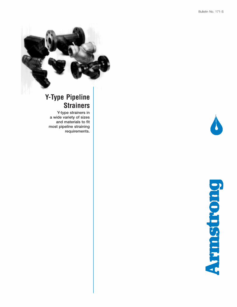
Bulletin No. 171-S Y-Type Pipeline Strainers Y-type strainers in a wide variety of sizes and materials to fit most pipeline straining requirements.
-
Upload
123balaram -
Category
Documents
-
view
226 -
download
7
Transcript of Y Strainer
Bulletin No. 171-S
Y-Type PipelineStrainers
Y-type strainers ina wide variety of sizes
and materials to fitmost pipeline straining
requirements.
2
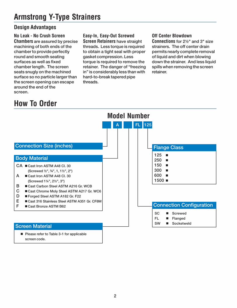
Armstrong Y-Type StrainersDesign Advantages
Easy-In, Easy-Out ScrewedScreen Retainers have straightthreads. Less torque is requiredto obtain a tight seal with propergasket compression. Lesstorque is required to remove theretainer. The danger of “freezingin” is considerably less than withhard-to-break tapered pipethreads.
No Leak - No Crush ScreenChambers are assured by precisemachining of both ends of thechamber to provide perfectlyround and smooth seatingsurfaces as well as fixedchamber length. The screenseats snugly on the machinedsurface so no particle larger thanthe screen opening can escapearound the end of the
Off Center BlowdownConnections for 2½" and 3" sizestrainers. The off center drainpermits nearly complete removalof liquid and dirt when blowingdown the strainer. And less liquidspills when removing the screenretainer.
CA nCast Iron ASTM A48 Cl. 30(Screwed ½", ¾", 1, 1½", 2")
A nCast Iron ASTM A48 Cl. 30
(Screwed 1¼", 2½", 3")B nCast Carbon Steel ASTM A216 Gr. WCBC nCast Chrome Moly Steel ASTM A217 Gr. WC6D nForged Steel ASTM A182 Gr. F22E nCast 316 Stainless Steel ASTM A351 Gr. CF8MF nCast Bronze ASTM B62
Connection Size (inches)
125 n
250 n
150 n
300 n
600 n
1500 n
n Please refer to Table 3-1 for applicablescreen code.
Screen Material
Body Material
A FL 125
Flange Class
Connection Configuration
How To Order
Model Number
SC n ScrewedFL n FlangedSW n Socketweld
screen.
3
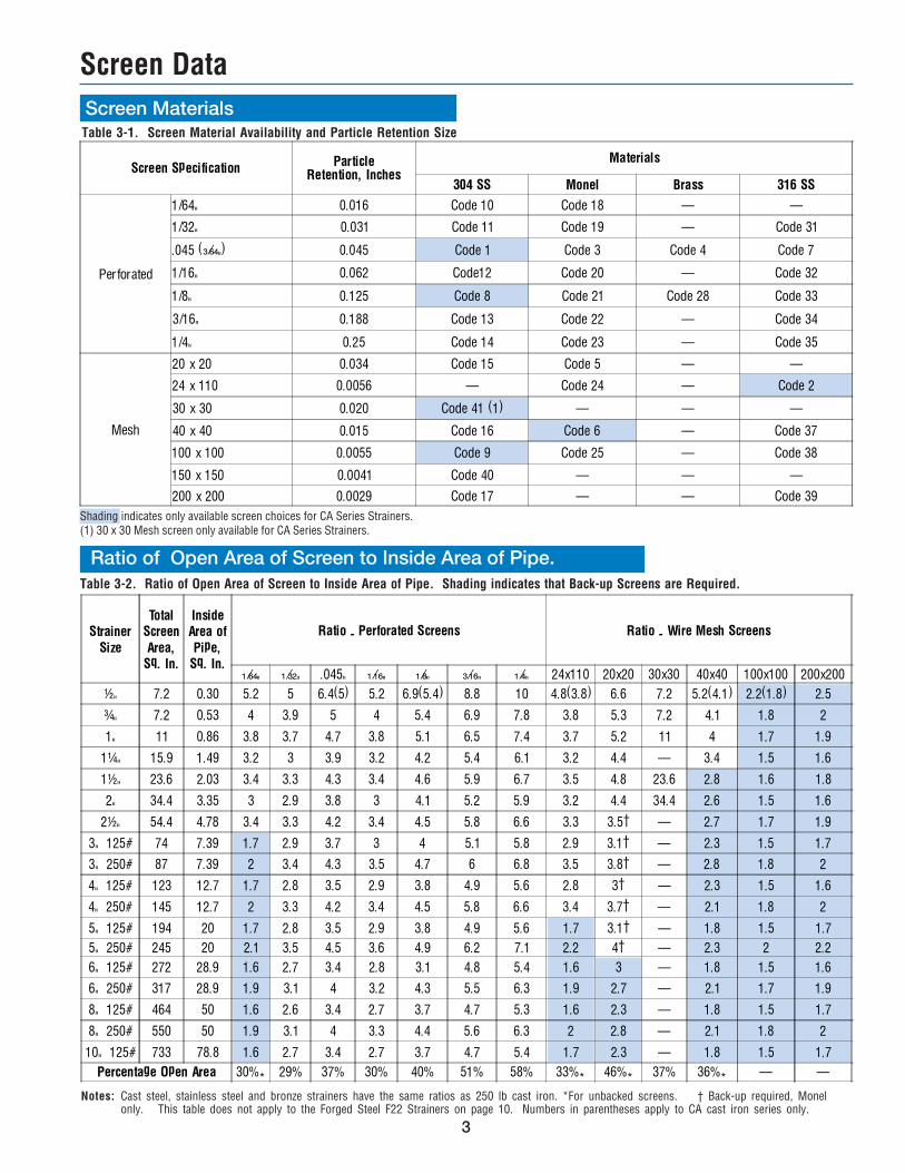
Strainer
Size
TotalScreen
Area,Sq. In.
InsideArea of
Pipe,Sq. In.
Ratio - Perforated Screens Ratio - Wire Mesh Screens
Z\nv" Z\cx" .045" Z\zn" Z\," C\zn" Z\v" 24x110 20x20 30x30 40x40 100x100 200x200
½" 7.2 0.30 5.2 5 6.4(5) 5.2 6.9(5.4) 8.8 10 4.8(3.8) 6.6 7.2 5.2(4.1) 2.2(1.8) 2.5
¾" 7.2 0.53 4 3.9 5 4 5.4 6.9 7.8 3.8 5.3 7.2 4.1 1.8 2
1" 11 0.86 3.8 3.7 4.7 3.8 5.1 6.5 7.4 3.7 5.2 11 4 1.7 1.9
1¼" 15.9 1.49 3.2 3 3.9 3.2 4.2 5.4 6.1 3.2 4.4 � 3.4 1.5 1.6
1½" 23.6 2.03 3.4 3.3 4.3 3.4 4.6 5.9 6.7 3.5 4.8 23.6 2.8 1.6 1.8
2" 34.4 3.35 3 2.9 3.8 3 4.1 5.2 5.9 3.2 4.4 34.4 2.6 1.5 1.6
2½" 54.4 4.78 3.4 3.3 4.2 3.4 4.5 5.8 6.6 3.3 3.5� � 2.7 1.7 1.9
3" 125# 74 7.39 1.7 2.9 3.7 3 4 5.1 5.8 2.9 3.1� � 2.3 1.5 1.7
3" 250# 87 7.39 2 3.4 4.3 3.5 4.7 6 6.8 3.5 3.8� � 2.8 1.8 2
4" 125# 123 12.7 1.7 2.8 3.5 2.9 3.8 4.9 5.6 2.8 3� � 2.3 1.5 1.6
4" 250# 145 12.7 2 3.3 4.2 3.4 4.5 5.8 6.6 3.4 3.7� � 2.1 1.8 2
5" 125# 194 20 1.7 2.8 3.5 2.9 3.8 4.9 5.6 1.7 3.1� � 1.8 1.5 1.7
5" 250# 245 20 2.1 3.5 4.5 3.6 4.9 6.2 7.1 2.2 4� � 2.3 2 2.2
6" 125# 272 28.9 1.6 2.7 3.4 2.8 3.1 4.8 5.4 1.6 3 � 1.8 1.5 1.6
6" 250# 317 28.9 1.9 3.1 4 3.2 4.3 5.5 6.3 1.9 2.7 � 2.1 1.7 1.9
8" 125# 464 50 1.6 2.6 3.4 2.7 3.7 4.7 5.3 1.6 2.3 � 1.8 1.5 1.7
8" 250# 550 50 1.9 3.1 4 3.3 4.4 5.6 6.3 2 2.8 � 2.1 1.8 2
10" 125# 733 78.8 1.6 2.7 3.4 2.7 3.7 4.7 5.4 1.7 2.3 � 1.8 1.5 1.7
Percentage Open Area 30%* 29% 37% 30% 40% 51% 58% 33%* 46%* 37% 36%* � �
Screen Data
Table 3-1. Screen Material Availability and Particle Retention Size
Screen Materials
Ratio of Open Area of Screen to Inside Area of Pipe.Table 3-2. Ratio of Open Area of Screen to Inside Area of Pipe. Shading indicates that Back-up Screens are Required.
Notes: Cast steel, stainless steel and bronze strainers have the same ratios as 250 lb cast iron. *For unbacked screens. † Back-up required, Monelonly. This table does not apply to the Forged Steel F22 Strainers on page 10. Numbers in parentheses apply to CA cast iron series only.
Shading indicates only available screen choices for CA Series Strainers.(1) 30 x 30 Mesh screen only available for CA Series Strainers.
Screen SpecificationParticle
Retention, Inches
Materials
304 SS Monel Brass 316 SS
Perforated
1/64" 0.016 Code 10 Code 18 � �
1/32" 0.031 Code 11 Code 19 � Code 31
.045 (C\nv") 0.045 Code 1 Code 3 Code 4 Code 7
1/16" 0.062 Code12 Code 20 � Code 32
1/8" 0.125 Code 8 Code 21 Code 28 Code 33
3/16" 0.188 Code 13 Code 22 � Code 34
1/4" 0.25 Code 14 Code 23 � Code 35
Mesh
20 x 20 0.034 Code 15 Code 5 � �
24 x 110 0.0056 � Code 24 � Code 2
30 x 30 0.020 Code 41 (1) � � �
40 x 40 0.015 Code 16 Code 6 � Code 37
100 x 100 0.0055 Code 9 Code 25 � Code 38
150 x 150 0.0041 Code 40 � � �
200 x 200 0.0029 Code 17 � � Code 39
4
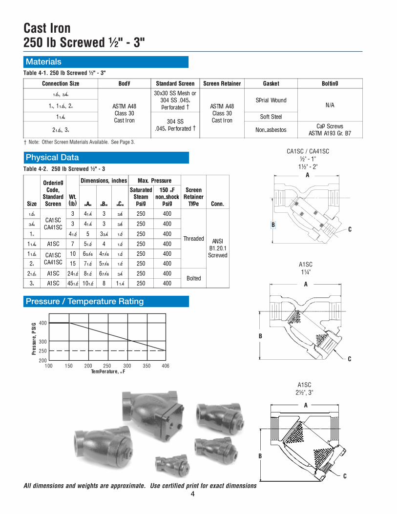
Materials
Table 4-2. 250 lb Screwed ½" - 3
† Note: Other Screen Materials Available. See Page 3.
Pressure / Temperature Rating
Table 4-1. 250 lb Screwed ½" - 3"
A1SC1¼"
A
A
A1SC2½", 3"
C
C
Cast Iron250 lb Screwed ½" - 3"
B
B
Physical Data
Connection Size Body Standard Screen Screen Retainer Gasket Bolting
Z\x", C\v"
ASTM A48Class 30Cast Iron
30x30 SS Mesh or304 SS .045"perforated � ASTM A48
Class 30Cast Iron
Sprial WoundN/A1", 1Z\x", 2"
1Z\v"304 SS
.045" perforated �
Soft Steel
2Z\x", 3" Non-asbestosCap Screws
ASTM A193 Gr. B7
Size
OrderingCode,
StandardScreen
Wt.(lb)
Dimensions, inches Max. Pressure
ScreenRetainer
Type Conn."A" "B" "C"
SaturatedSteampsig
150 °Fnon-shock
psig
Z\x"CA1SCCA41SC
3 4Z\v 3 C\, 250 400
Threaded ANSIB1.20.1Screwed
C\v" 3 4Z\v 3 C\, 250 400
1" 4Z\x 5 3C\v Z\x 250 400
1Z\v" A1SC 7 5Z\x 4 Z\x 250 400
1Z\x" CA1SCCA41SC
10 6B\zn 4M\zn Z\x 250 400
2" 15 7Z\x 5M\zn Z\x 250 400
2Z\x" A1SC 24Z\x 8Z\x 6M\zn C\v 250 400Bolted
3" A1SC 45Z\x 10Z\x 8 1Z\v 250 400
All dimensions and weights are approximate. Use certified print for exact dimensions
400
300
250
200100 150 200 250 300 350 406
Pre
ssu
re,
PSIG
Temperature, ° F
CA1SC / CA41SC½" - 1"
1½" - 2"A
BC
�
�
� �
5
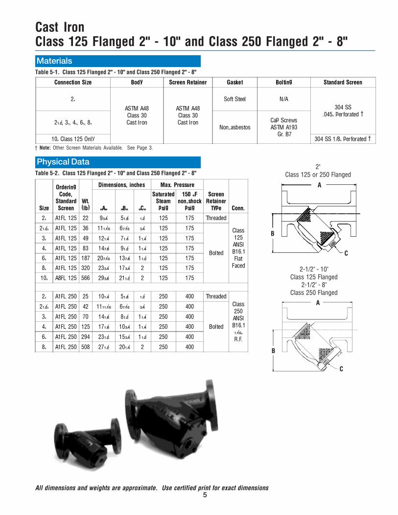
Materials
Cast IronClass 125 Flanged 2" - 10" and Class 250 Flanged 2" - 8"
Table 5-1. Class 125 Flanged 2" - 10" and Class 250 Flanged 2" - 8"
Connection Size Body Screen Retainer Gasket Bolting Standard Screen
2"
ASTM A48Class 30Cast Iron
ASTM A48Class 30Cast Iron
Soft Steel N/A
304 SS.045" perforated �
2Z\x, 3", 4", 6", 8"Non-asbestos
Cap ScrewsASTM A193
Gr. B710" Class 125 Only 304 SS 1/8" perforated �
† Note: Other Screen Materials Available. See Page 3.
Table 5-2. Class 125 Flanged 2" - 10" and Class 250 Flanged 2" - 8"
Physical Data
Size
OrderingCode,
StandardScreen
Wt.(lb)
Dimensions, inches Max. Pressure
ScreenRetainer
Type Conn."A" "B" "C"
SaturatedSteampsig
150 °Fnon-shock
psig
2" A1FL 125 22 9C\v 5Z\, Z\x 125 175 Threaded
Class125
ANSIB16.1Flat
Faced
2Z\x" A1FL 125 36 11Z\zn 6M\zn C\v 125 175
Bolted
3" A1FL 125 49 12Z\v 7Z\v 1Z\v 125 175
4" A1FL 125 83 14M\, 9Z\x 1Z\v 125 175
6" A1FL 125 187 20M\zn 13M\, 1Z\x 125 175
8" A1FL 125 320 23C\v 17C\v 2 125 175
10" A8FL 125 566 29C\, 21Z\x 2 125 175
2" A1FL 250 25 10Z\v 5Z\, Z\x 250 400 Threaded
Class250ANSIB16.1Z\zn"R.F.
2Z\x" A1FL 250 42 11ZZ\zn 6M\zn C\v 250 400
Bolted
3" A1FL 250 70 14Z\, 8Z\x 1Z\v 250 400
4" A1FL 250 125 17Z\, 10C\v 1Z\v 250 400
6" A1FL 250 294 23Z\x 15C\v 1Z\x 250 400
8" A1FL 250 508 27Z\x 20Z\v 2 250 400
2"Class 125 or 250 Flanged
A
B
C
A
B
C
2-1/2" - 10"Class 125 Flanged
2-1/2" - 8"Class 250 Flanged
All dimensions and weights are approximate. Use certified print for exact dimensions
6
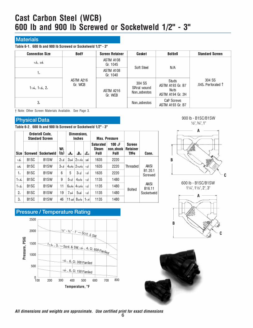
Materials
Cast Carbon Steel (WCB)600 lb and 900 lb Screwed or Socketweld 1/2" - 3"
Table 6-1. 600 lb and 900 lb Screwed or Socketweld 1/2" - 3"
Connection Size Body Screen Retainer Gasket Bolting Standard Screen
Z\x", C\v"
ASTM A216Gr. WCB
ASTM A108Gr. 1045
Soft Steel N/A
304 SS.045" Perforated �
1"ASTM A108
Gr. 1040
1Z\v", 1Z\x", 2"ASTM A216
Gr. WCB
304 SSSpiral woundNon-asbestos
StudsASTM A193 Gr. B7
NutsASTM A194 Gr. 2H
3" Non-asbestosCap Screws
ASTM A193 Gr. B7
† Note: Other Screen Materials Available. See Page 3.
Physical DataTable 6-2. 600 lb and 900 lb Screwed or Socketweld 1/2" - 3"
Size
Ordering Code,Standard Screen
Wt.(lb)
Dimensions,Inches Max. Pressure
ScreenRetainer
Type Conn.Screwed Socketweld "A" "B" "C"
SaturatedSteampsig
100 °Fnon-shock
psig
Z\x" B1SC B1SW 2Z\x 3C\v 2ZZ\zn C\, 1635 2220
Threaded ANSIB1.20.1Screwed
ANSIB16.11
Socketweld
C\v" B1SC B1SW 3Z\x 4C\zn 2ZB\zn Z\x 1635 2220
1" B1SC B1SW 6 5 3Z\x Z\x 1635 2220
1Z\v" B1SC B1SW 9 5Z\x 4C\zn Z\x 1135 1480
Bolted1Z\x" B1SC B1SW 11 6B\zn 4ZC\zn Z\x 1135 1480
2" B1SC B1SW 19 7C\v 5B\, Z\x 1135 1480
3" B1SC B1SW 46 11C\, 8C\zn 1Z\v 1135 1480
900 lb - B1SC/B1SW¹⁄₂", ³⁄₄", 1"
600 lb - B1SC/B1SW1¹⁄₄", 1¹⁄₂", 2", 3"
A
B
C
A
B
C
All dimensions and weights are approximate. Use certified print for exact dimensions
Pressure / Temperature Rating
1Z\ v� - - 4� C
3� � Scrd. & SW, � Z\x l. 600 Flanged
Z\x� - 6� Cl. 300 Flanged
Z\x� - 6� Cl. 150 Flanged
2500
2000
1500
1000
500
0100 200 300 400 500 600 700 800
Temperature, °F
Pres
sure
, PSI
G
7
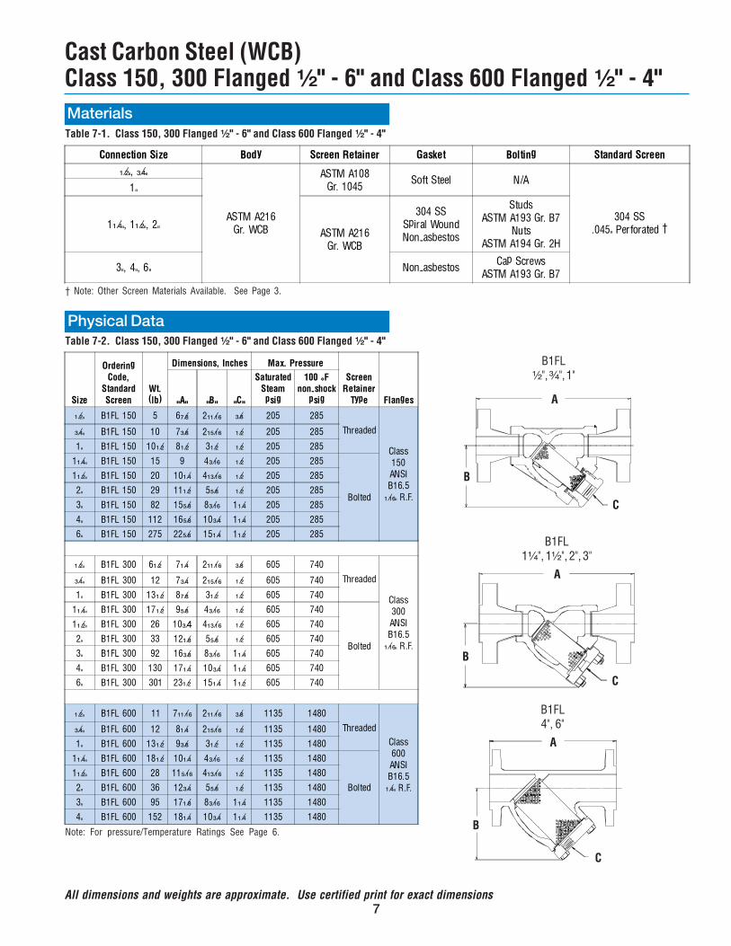
Materials
Cast Carbon Steel (WCB)Class 150, 300 Flanged ¹⁄₂" - 6" and Class 600 Flanged ¹⁄₂" - 4"
Table 7-1. Class 150, 300 Flanged ¹⁄₂" - 6" and Class 600 Flanged ¹⁄₂" - 4"
Connection Size Body Screen Retainer Gasket Bolting Standard Screen
Z\x", C\v"
ASTM A216Gr. WCB
ASTM A108Gr. 1045
Soft Steel N/A
304 SS.045" Perforated �
1"
1Z\v", 1Z\x", 2"ASTM A216
Gr. WCB
304 SSSpiral WoundNon-asbestos
StudsASTM A193 Gr. B7
NutsASTM A194 Gr. 2H
3", 4", 6" Non-asbestosCap Screws
ASTM A193 Gr. B7
Physical DataTable 7-2. Class 150, 300 Flanged ¹⁄₂" - 6" and Class 600 Flanged ¹⁄₂" - 4"
† Note: Other Screen Materials Available. See Page 3.
Size
Ordering
Code,
Standard
Screen
Wt.
(lb)
Dimensions, Inches Max. Pressure
Screen
Retainer
Type Flanges"A" "B" "C"
Saturated
Steam
psig
100 °F
non-shock
psig
Z\x" B1FL 150 5 6M\, 2ZZ\zn C\, 205 285
Threaded
Class150
ANSIB16.5
Z\zn" R.F.
C\v" B1FL 150 10 7C\, 2ZB\zn Z\x 205 285
1" B1FL 150 10Z\x 8Z\x 3Z\x Z\x 205 285
1Z\v" B1FL 150 15 9 4C\zn Z\x 205 285
Bolted
1Z\x" B1FL 150 20 10Z\v 4ZC\zn Z\x 205 285
2" B1FL 150 29 11Z\x 5B\, Z\x 205 285
3" B1FL 150 82 15B\, 8C\zn 1Z\v 205 285
4" B1FL 150 112 16B\, 10C\v 1Z\v 205 285
6" B1FL 150 275 22B\, 15Z\v 1Z\x 205 285
Z\x" B1FL 300 6Z\x 7Z\v 2ZZ\zn C\, 605 740
Threaded
Class300
ANSIB16.5
Z\zn" R.F.
C\v" B1FL 300 12 7C\v 2ZB\zn Z\x 605 740
1" B1FL 300 13Z\x 8M\, 3Z\x Z\x 605 740
1Z\v" B1FL 300 17Z\x 9B\, 4C\zn Z\x 605 740
Bolted
1Z\x" B1FL 300 26 10C\4 4ZC\zn Z\x 605 740
2" B1FL 300 33 12Z\, 5B\, Z\x 605 740
3" B1FL 300 92 16C\, 8C\zn 1Z\v 605 740
4" B1FL 300 130 17Z\v 10C\v 1Z\v 605 740
6" B1FL 300 301 23Z\x 15Z\v 1Z\x 605 740
Z\x" B1FL 600 11 7ZZ\zn 2ZZ\zn C\, 1135 1480
Threaded
Class600
ANSIB16.5Z\v" R.F.
C\v" B1FL 600 12 8Z\v 2ZB\zn Z\x 1135 1480
1" B1FL 600 13Z\x 9C\, 3Z\x Z\x 1135 1480
1Z\v" B1FL 600 18Z\x 10Z\v 4C\zn Z\x 1135 1480
Bolted
1Z\x" B1FL 600 28 11B\zn 4ZC\zn Z\x 1135 1480
2" B1FL 600 36 12C\v 5B\, Z\x 1135 1480
3" B1FL 600 95 17Z\, 8C\zn 1Z\v 1135 1480
4" B1FL 600 152 18Z\v 10C\v 1Z\v 1135 1480
All dimensions and weights are approximate. Use certified print for exact dimensions
Note: For pressure/Temperature Ratings See Page 6.
B1FL¹⁄₂", ³⁄₄", 1"
A
B
C
B1FL1¹⁄₄", 1¹⁄₂", 2", 3"
A
B
C
B1FL4", 6"
A
B
C
8
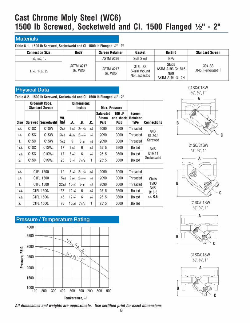
Cast Chrome Moly Steel (WC6)1500 lb Screwed, Socketweld and Cl. 1500 Flanged ¹⁄₂" - 2" MaterialsTable 8-1. 1500 lb Screwed, Socketweld and Cl. 1500 lb Flanged ¹⁄₂" - 2"
Connection Size Body Screen Retainer Gasket Bolting Standard Screen
Z\x", C\v", 1"
ASTM A217Gr. WC6
ASTM A276 Soft Steel N/A
304 SS.045" perforated �1Z\v", 1Z\x", 2"
ASTM A217Gr. WC6
316L SSSpiral WoundNon-asbestos
StudsASTM A193 Gr. B16
NutsASTM A194 Gr. 2H
Size
Ordering Code,Standard Screen
Wt.(lb)
Dimensions,Inches Max. Pressure
ScreenRetainer
Type ConnectionsScrewed Socketweld "A" "B" "C"
SaturatedSteampsig
100 °Fnon-shock
psig
Z\x" C1SC C1SW 2Z\x 3C\v 2ZZ\zn C\, 2090 3000 ThreadedANSI
B1.20.1Screwed
ANSIB16.11
Socketweld
C\v" C1SC C1SW 3Z\x 4C\zn 2ZB\zn Z\x 2090 3000 Threaded
1" C1SC C1SW 5Z\x 5 3Z\x Z\x 2090 3000 Threaded
1Z\v" C1SC C1SW* 17 6C\v 6 C\v 2515 3600 Bolted
1Z\x" C1SC C1SW* 17 6C\v 6 C\v 2515 3600 Bolted
2" C1SC C1SW* 25 8Z\v 7M\zn 1 2515 3600 Bolted
Z\x" C1FL 1500 12 8Z\v 2ZZ\zn C\, 2090 3000 Threaded
Class1500ANSIB16.5Z\v" R.F.
C\v" C1FL 1500 15Z\x 9C\, 2ZB\zn Z\x 2090 3000 Threaded
1" C1FL 1500 22Z\x 10Z\v 3Z\x Z\x 2090 3000 Threaded
1Z\v" C1FL 1500* 37 12Z\, 6 C\v 2515 3600 Bolted
1Z\x" C1FL 1500* 45 12M\, 6 C\v 2515 3600 Bolted
2" C1FL 1500* 78 15B\, 7M\zn 1 2515 3600 Bolted
Physical DataTable 8-2. 1500 lb Screwed, Socketweld and Cl. 1500 lb Flanged ¹⁄₂" - 2"
C1SC/C1SW¹⁄₂", ³⁄₄", 1"
B
C
A
C1SC/C1SW¹⁄₂", ³⁄₄", 1"
B
C
A
C1SC/C1SW¹⁄₂", ³⁄₄", 1"
B
C
A
C1SC/C1SW¹⁄₂", ³⁄₄", 1"
B
C
A
Pressure / Temperature Rating
All dimensions and weights are approximate. Use certified print for exact dimensions
1Z\v� - 1�
Z\x- 2�
4000
3500
3000
2500
2000
1500
1000100 200 300 400 500 600 700 800 900
Temperature, °F
Pre
ssur
e, P
SIG
9All dimensions and weights are approximate. Use certified print for exact dimensions
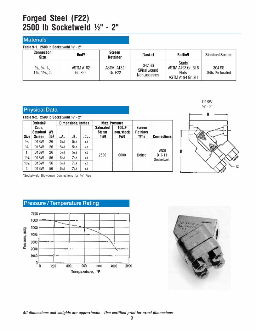
Forged Steel (F22)2500 lb Socketweld ½" - 2" MaterialsTable 9-1. 2500 lb Socketweld ½" - 2"
ConnectionSize
BodyScreen
RetainerGasket Bolting Standard Screen
½", ¾", 1",1¼", 1½", 2"
ASTM A182Gr. F22
ASTM A182 Gr. F22
347 SSSpiral woundNon-asbestos
StudsASTM A193 Gr. B16
NutsASTM A194 Gr. 2H
304 SS.045" perforated
Pressure / Temperature Rating
*Socketweld Blowdown Connections for ¹⁄₂" Pipe
Physical Data
Size
OrderingCode,
StandardScreen
Wt.(lb)
Dimensions, inches Max. PressureScreen
RetainerType Connections�A� �B� �C*�
SaturatedSteam psig
100°Fnon-shock
psig
½" D1SW 26 5Z\, 5B\, Z\x
2500 6000 Bolted ANSI
B16.11Socketweld
¾" D1SW 26 5Z\, 5B\, Z\x
1" D1SW 26 5Z\, 5B\, Z\x
1¼" D1SW 56 6B\, 7C\, Z\x
1½" D1SW 56 6B\, 7C\, Z\x
2" D1SW 56 6B\, 7C\, Z\x
Table 9-2. 2500 lb Socketweld ½" - 2"
D1SW½" - 2"
10
Cast Stainless Steel (CF8M)1500 lb and 600 lb Screwed or Socketweld ½" - 3" MaterialsTable 10-1. 1500 lb and 600 lb Screwed or Socketweld ½" - 3"
ConnectionSize
BodyScreen
RetainerGasket Bolting Standard Screen
½", ¾", 1"
ASTM A351Gr. CF8M
ASTM A276316 SS
FlatN/A
316 SS.045" perforated
1¼", 1½", 2"ASTM A351Gr. CF8M
304 SSSpiral woundNon-asbestos
StudsASTM A193 Gr. B7
NutsASTM A194 Gr. 2H
3" Non-asbestosCap Screws
ASTM A193 Gr. B7
All dimensions and weights are approximate. Use certified print for exact dimensions
† Note: Other Screen Materials Available. See Page 3.
†
Table 10-2. 1500 lb and 600 lb Screwed or Socketweld ½" - 3"
Size
Ordering Code,Standard Screen
Wt.(lb)
Dimensions,inches Max. Pressure
Screen
RetainerType ConnectionsScrewed Socketweld �A� �B� �C�
Saturated
Steampsig
100°F
non-shockpsig
½" E7SC E7SW 2½ 3C\v 2ZZ\zn C\, 2090 3000
ThreadedANSI
B1.20.1Screwed
ANSIB16.11
Socketweld
¾ E7SC E7SW 3½ 4C\zn 2ZB\zn Z\x 2090 3000
1" E7SC E7SW 6 5 3Z\x Z\x 2090 3000
1¼" E7SC E7SW 9 5Z\x 4C\zn Z\x 935 1440
Bolted1½" E7SC E7SW 11 6B\zn 4ZC\zn Z\x 935 1440
2" E7SC E7SW 19 7C\v 5B\, Z\x 935 1440
3" E7SC E7SW 50 11C\, 8C\zn 1Z\v 935 1440
Physical Data
Pressure / Temperature Rating
E7SC/E7SW½", ¾", 1"
E7SC/E7SW1¼", 1½", 2", 3"
11
Cast Stainless Steel (CF8M)Cl. 150, 300 Flanged ½" - 6" and Cl. 600 Flanged ½" - 4" MaterialsTable 11-1. Cl. 150, 300 Flanged ½" - 6" and Cl. 600 Flanged ½" - 4"
ConnectionSize
BodyScreen
RetainerGasket Bolting Standard Screen
½", ¾", 1"
ASTM A351Gr. CF8M
ASTM A276316 SS
FlatN/A
316 SS.045" perforated
1½", 2"ASTM A351Gr. CF8M
304 SSSpiral woundNon-asbestos
StudsASTM A193 Gr. B7
NutsASTM A194 Gr. 2H
3", 4", 6" Non-asbestosCap Screws
ASTM A193 Gr. B7
Table 11-2. Cl. 150, 300 Flanged ½" - 6" and Cl. 600 Flanged ½" - 4"
† Note: Other Screen Materials Available. See Page 3.
All dimensions and weights are approximate. Use certified print for exact dimensions
†
Note: For Pressure/Temperature Ratings See Page 10.
Physical Data
Size
OrderingCode,
StandardScreen
Wt.(lb)
Dimensions,inches Max. Pressure
ScreenRetainer
TypeFlanges
Type�A� �B� �C�
SaturatedSteampsig
100°Fnon-shock
psig
½" E7FL 150 5 6M\, 2ZZ\zn C\, 200 275
Threaded
ANSIB16.5
Z\zn" R.F.
¾" E7FL 150 10 7C\, 2ZB\zn Z\x 200 275
1" E7FL 150 11 8C\, 3Z\x Z\x 200 275
1½" E7FL 150 20 10Z\, 4ZC\zn Z\x 200 275
Bolted
2" E7FL 150 25 11Z\x 5B\, Z\x 200 275
3" E7FL 150 55 15B\, 8C\zn 1Z\v 200 275
4" E7FL 150 79 16B\, 10C\v 1Z\v 200 275
6" E7FL 150 � 22B\, 15Z\v 1Z\x 200 275
½" E7FL 300 6Z\x 7Z\v 2ZZ\zn C\, 495 720
Threaded
ANSIB16.5
Z\zn" R.F.
¾" E7FL 300 9Z\x 7C\v 2ZB\zn Z\x 495 720
1" E7FL 300 13Z\x 8M\, 3Z\x Z\x 495 720
1½" E7FL 300 22 10C\v 4ZC\zn Z\x 495 720
Bolted
2" E7FL 300 33 12Z\, 5B\, Z\x 495 720
3" E7FL 300 74 16C\, 8C\zn 1Z\v 495 720
4" E7FL 300 144 17Z\v 10C\v 1Z\v 495 720
6" E7FL 300 301 23Z\x 15Z\v 1Z\x 495 720
½" E7FL 600 8Z\x 7ZZ\zn 2ZZ\zn C\, 935 1440
Threaded
ANSIB16.5Z\v" R.F.
¾" E7FL 600 9Z\x 8Z\v 2ZB\zn Z\x 935 1440
1" E7FL 600 13Z\x 9C\, 3Z\x Z\x 935 1440
1½" E7FL 600 27 11B\zn 4ZC\zn Z\x 935 1440
Bolted2" E7FL 600 31 12C\v 5B\, Z\x 935 1440
3" E7FL 600 74 17Z\, 8C\zn 1Z\v 935 1440
4" E7FL 600 152 18Z\v 10C\v 1Z\v 935 1440
E7FL½", ¾", 1"
E7FL1½", 2", 3"
E7FL4", 6"
12
Cast Bronze300 lb Screwed ½" - 2" MaterialsTable 12-1. 300 lb Screwed ½" - 2"
ConnectionSize
BodyScreen
RetainerGasket Bolting Standard Screen
½", ¾", 1"1¼", 1½", 2"
ASTM B62 Brass Copper N/ABrass
.045" perforated
Table 12-2. 300 lb Screwed ½" - 2"
Physical Data
Size
OrderingCode,
StandardScreen
Wt.(lb)
Dimensions, inches Max. PressureScreen
RetainerType Connections�A� �B� �C�
SaturatedSteampsig
150°Fnon-shock
psig
½" F4SC 1½ 3Z\x 2Z\x C\, 300 500
ThreadedANSI
B1.20.1Screwed
¾" F4SC 2 4 2M\, Z\x 300 500
1" F4SC 3½ 4C\v 3B\zn Z\x 300 500
1¼" F4SC 5 5Z\v 4 Z\x 300 500
1½" F4SC 7½ 6 4C\, Z\x 300 500
2" F4SC 12 7 5Z\x Z\x 300 500
Pressure / Temperature Rating
† Note: Other Screen Materials Available. See Page 3.
†
500
400
300
200
1000 150 200 250 300 350 400 422
Pre
ssure
Psi
g
Temperature, °F
A
B
F4SC½" - 2"
C
13
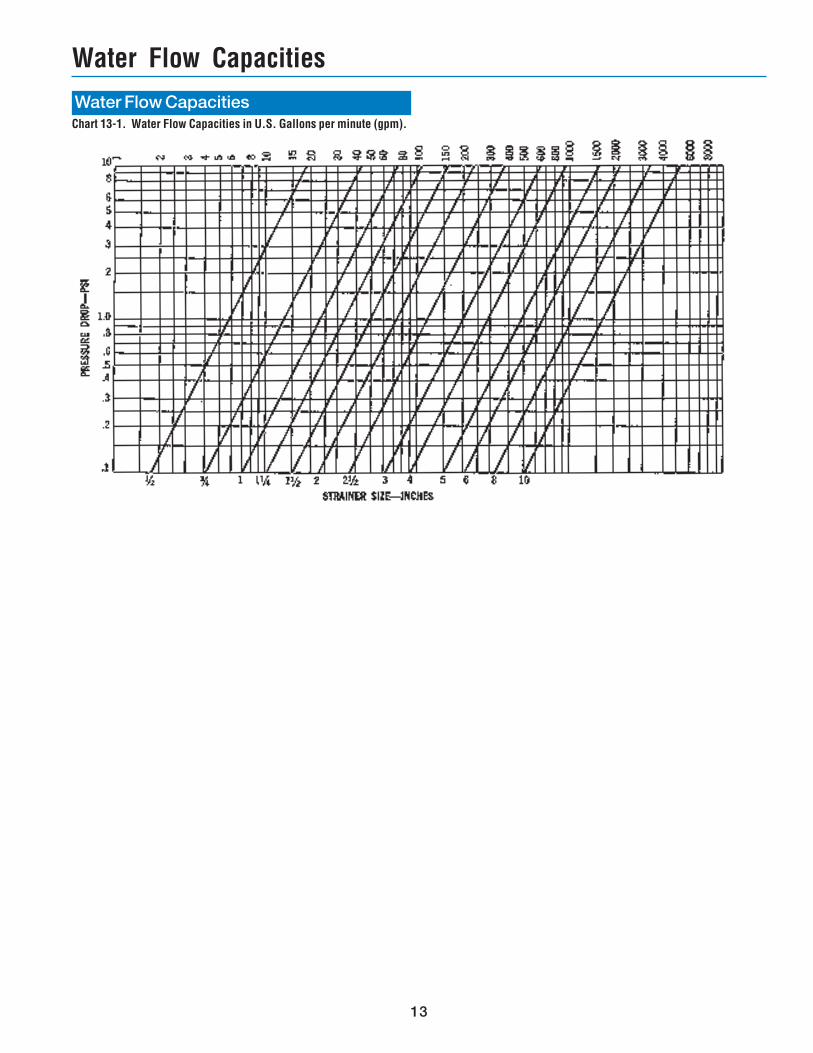
Water Flow Capacities
Water Flow Capacities
Chart 13-1. Water Flow Capacities in U.S. Gallons per minute (gpm).
14Bulletin No. 171-S 8/98 6M Printed in U.S.A.
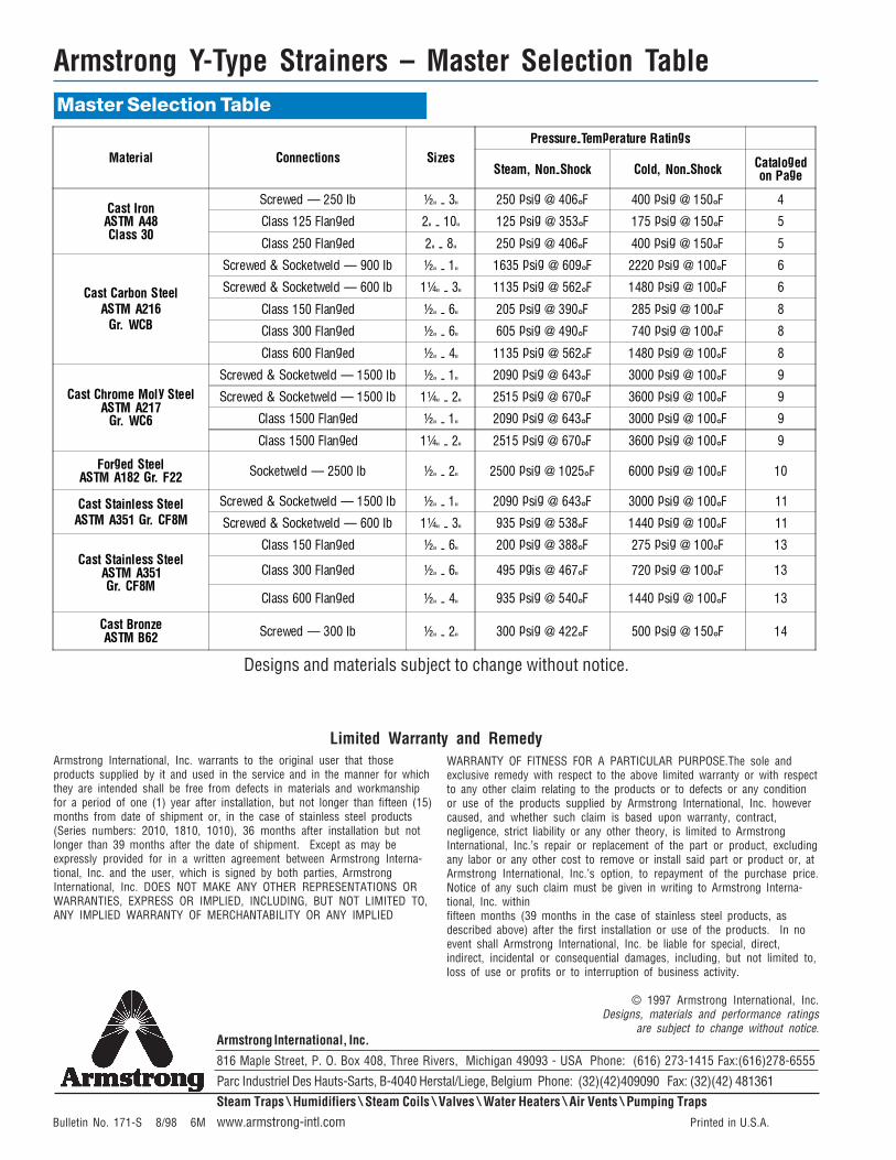
Armstrong Y-Type Strainers – Master Selection Table
Designs and materials subject to change without notice.
Armstrong International, Inc. warrants to the original user that thoseproducts supplied by it and used in the service and in the manner for whichthey are intended shall be free from defects in materials and workmanshipfor a period of one (1) year after installation, but not longer than fifteen (15)months from date of shipment or, in the case of stainless steel products(Series numbers: 2010, 1810, 1010), 36 months after installation but notlonger than 39 months after the date of shipment. Except as may beexpressly provided for in a written agreement between Armstrong Interna-tional, Inc. and the user, which is signed by both parties, ArmstrongInternational, Inc. DOES NOT MAKE ANY OTHER REPRESENTATIONS ORWARRANTIES, EXPRESS OR IMPLIED, INCLUDING, BUT NOT LIMITED TO,ANY IMPLIED WARRANTY OF MERCHANTABILITY OR ANY IMPLIED
WARRANTY OF FITNESS FOR A PARTICULAR PURPOSE.The sole andexclusive remedy with respect to the above limited warranty or with respectto any other claim relating to the products or to defects or any conditionor use of the products supplied by Armstrong International, Inc. howevercaused, and whether such claim is based upon warranty, contract,negligence, strict liability or any other theory, is limited to ArmstrongInternational, Inc.’s repair or replacement of the part or product, excludingany labor or any other cost to remove or install said part or product or, atArmstrong International, Inc.’s option, to repayment of the purchase price.Notice of any such claim must be given in writing to Armstrong Interna-tional, Inc. withinfifteen months (39 months in the case of stainless steel products, asdescribed above) after the first installation or use of the products. In noevent shall Armstrong International, Inc. be liable for special, direct,indirect, incidental or consequential damages, including, but not limited to,loss of use or profits or to interruption of business activity.
© 1997 Armstrong International, Inc.Designs, materials and performance ratings
are subject to change without notice.
Limited Warranty and Remedy
Master Selection Table
Armstrong International, Inc.816 Maple Street, P. O. Box 408, Three Rivers, Michigan 49093 - USA Phone: (616) 273-1415 Fax:(616)278-6555
Parc Industriel Des Hauts-Sarts, B-4040 Herstal/Liege, Belgium Phone: (32)(42)409090 Fax: (32)(42) 481361Steam Traps \ Humidifiers \ Steam Coils \ Valves \ Water Heaters \ Air Vents \ Pumping Trapswww.armstrong-intl.com
Material Connections Sizes
Pressure-Temperature Ratings
Steam, Non-Shock Cold, Non-ShockCatalogedon Page
Cast IronASTM A48Class 30
Screwed � 250 lb ½" - 3" 250 psig @ 406°F 400 psig @ 150°F 4
Class 125 Flanged 2" - 10" 125 psig @ 353°F 175 psig @ 150°F 5
Class 250 Flanged 2" - 8" 250 psig @ 406°F 400 psig @ 150°F 5
Cast Carbon SteelASTM A216
Gr. WCB
Screwed & Socketweld � 900 lb ½" - 1" 1635 psig @ 609°F 2220 psig @ 100°F 6
Screwed & Socketweld � 600 lb 1¼" - 3" 1135 psig @ 562°F 1480 psig @ 100°F 6
Class 150 Flanged ½" - 6" 205 psig @ 390°F 285 psig @ 100°F 8
Class 300 Flanged ½" - 6" 605 psig @ 490°F 740 psig @ 100°F 8
Class 600 Flanged ½" - 4" 1135 psig @ 562°F 1480 psig @ 100°F 8
Cast Chrome Moly SteelASTM A217
Gr. WC6
Screwed & Socketweld � 1500 lb ½" - 1" 2090 psig @ 643°F 3000 psig @ 100°F 9
Screwed & Socketweld � 1500 lb 1¼" - 2" 2515 psig @ 670°F 3600 psig @ 100°F 9
Class 1500 Flanged ½" - 1" 2090 psig @ 643°F 3000 psig @ 100°F 9
Class 1500 Flanged 1¼" - 2" 2515 psig @ 670°F 3600 psig @ 100°F 9
Forged SteelASTM A182 Gr. F22 Socketweld � 2500 lb ½" - 2" 2500 psig @ 1025°F 6000 psig @ 100°F 10
Cast Stainless SteelASTM A351 Gr. CF8M
Screwed & Socketweld � 1500 lb ½" - 1" 2090 psig @ 643°F 3000 psig @ 100°F 11
Screwed & Socketweld � 600 lb 1¼" - 3" 935 psig @ 538°F 1440 psig @ 100°F 11
Cast Stainless SteelASTM A351Gr. CF8M
Class 150 Flanged ½" - 6" 200 psig @ 388°F 275 psig @ 100°F 13
Class 300 Flanged ½" - 6" 495 pgis @ 467°F 720 psig @ 100°F 13
Class 600 Flanged ½" - 4" 935 psig @ 540°F 1440 psig @ 100°F 13
Cast BronzeASTM B62 Screwed � 300 lb ½" - 2" 300 psig @ 422°F 500 psig @ 150°F 14