Xylem Water Solutions AB (the Company) was previously ... · PDF fileEntrance flange SS...
54
Xylem Water Solutions AB (the Company) was previously named ITT Water & Wastewater AB. The name change took place in November 2011. This is document is (i) a document that relates to a product of the Company phased out prior to the name change; or (ii) an old version of documentation relating to a product that is still being produced by the Company but which document was published prior to the 1st of January 2012 . This document may therefore still be marked "ITT". Xylem Water Solutions AB is no longer an ITT company and the fact that "ITT" may appear on this document shall not be interpreted as a reference by the Company to "ITT" in the Company's current business activities. Any use or reference to “ITT” by you is strictly prohibited. In no event will we be liable for any incidental, indirect, consequential, punitive or special damages of any kind, or any other damages whatsoever, including, without limitation, those resulting from loss of profit, loss of contracts, loss of reputation, goodwill, data, information, income, anticipated savings or business relationships for any use by you of “ITT”. This disclaimer notice shall be interpreted and governed by Swedish law, and any disputes in relation to it are subject to the jurisdiction of the courts in Sweden. If you do not agree to these terms and conditions you should not print this document and immediately stop accessing it.
Transcript of Xylem Water Solutions AB (the Company) was previously ... · PDF fileEntrance flange SS...

Xylem Water Solutions AB (the Company) was previously named ITT Water & Wastewater AB. The name change took place in November 2011. This is document is (i) a document that relates to a product of the Company phased out prior to the name change; or (ii) an old version of documentation relating to a product that is stil l being produced by the Company but which document was published prior to the 1st of January 2012 . This document may therefore stil l be marked "ITT". Xylem Water Solutions AB is no longer an ITT company and the fact that "ITT" may appear on this document shall not be interpreted as a reference by the Company to "ITT" in the Company's current business activities. Any use or reference to “ITT” by you is strictly prohibited. In no event will we be liable for any incidental, indirect, consequential, punitive or special damages of any kind, or any other damages whatsoever, including, without limitation, those resulting from loss of profit, loss of contracts, loss of reputation, goodwill, data, information, income, anticipated savings or business relationships for any use by you of “ITT”. This disclaimer notice shall be interpreted and governed by Swedish law, and any disputes in relation to it are subject to the jurisdiction of the courts in Sweden. If you do not agree to these terms and conditions you should not print this document and immediately stop accessing it.

End of Disclaimer text.

Parts ListFlygt 3153.091/095/181/185


Parts List
Flygt 3153.091/095/181/185
Overview
Table of Contents This publication contains the following topics:
Topic
Preface ...................................................................................................................................................... 4Practical information ................................................................................................................................... 5
Data plate interpretation ......................................................................................................................... 6Product denomination ............................................................................................................................ 9Order parts ............................................................................................................................................11
Motor Parts ................................................................................................................................................12Explosion-proof......................................................................................................................................13Standard ...............................................................................................................................................15List........................................................................................................................................................17
Hydraulic Parts ...........................................................................................................................................24N_ LT ....................................................................................................................................................25N_ MT...................................................................................................................................................27N_ HT ...................................................................................................................................................28N_ SH...................................................................................................................................................29List........................................................................................................................................................30
Sump Components .....................................................................................................................................36NP ........................................................................................................................................................37NS .......................................................................................................................................................39NT LT....................................................................................................................................................41NT MT/HT/SH........................................................................................................................................42NZ ........................................................................................................................................................43List........................................................................................................................................................44
Parts for Service .........................................................................................................................................47List........................................................................................................................................................48
Parts List, Flygt 3153.091/095/181/185 3

Preface
Purpose The purpose of this document is to give the reader information about parts and accessoriesfor the product.
Recipient The document is intended for ITT
• customers
• service personnel
• sales personnel
Contact For more information
• contact your ITT representative
• visit http://www.ittwww.com/
Reference More information about the product is available at http://webservices.ittwww.com/tpi/.
4 Parts List, Flygt 3153.091/095/181/185

Practical information
Overview
Table ofContents
This chapter contains the following topics:
Topic
Data plate interpretation ..................................................................................... 6Data plate ..................................................................................................... 6Approval plate ............................................................................................... 7
Product denomination......................................................................................... 9Order parts ........................................................................................................ 11
Parts List, Flygt 3153.091/095/181/185 5

Data plate interpretation
Introduction The ITT product is always provided with data plates:
• The general data plate is used on all products.
• The approval plate is added to all explosion proof products.
Data plate
The product may only be operated within the parameters stated on the data plate.
Illustration This is an illustration of a general data plate.
1211 13
2120
19161514
8
7
6
5
4
2 1
22
2423
1817109
3
Fielddescription
This table shows the fields on the general data plate, and which information each fieldcontains.
Field Description Field Description
1 Curve code/Propeller code 13 Rated current
2 Serial number 14 Rated speed
3 Product number 15 Maximum submergence
4 Country of origin 16 Direction of rotation:
• L = Left
• R = Right
5 Additional information 17 Duty class
6 Phase; type of current,frequency
18 Duty factor
7 Rated voltage 19 Product weight
8 Thermal protection 20 Locked rotor code letter
9 Thermal class 21 Power factor
6 Parts List, Flygt 3153.091/095/181/185

Field Description Field Description
10 Rated shaft power 22 Maximal ambient temperature
11 International standard 23 Read Installation Manual
12 Degree of protection 24 Notified body (only forEN-approved Ex-products)
Approval plate
The approval is shown on the approval plate.
FM approvedversion
Illustration This is an illustration of an approval plate for the FM approved product version.
2
1
Fielddescription
This table shows the fields on the approval plate, and which information each field contains.
Field Description
1 Temperature class
2 Maximum ambient temperature
EN approvedversion
Illustration This is an illustration of an approval plate for the EN approved product version.
Parts List, Flygt 3153.091/095/181/185 7

Fielddescription
This table shows the fields on the approval plate.
Field Description Field Description
A Approval I Input power
B Approval authority + ApprovalNumber
J Rated speed
C Approval for Class 1 K Controller
D Approved drive unit L Additional information
E Stall time M Max. ambient temperature
F Starting current / Rated current N Serial number
G Duty class O ATEX marking
H Duty factor - -
8 Parts List, Flygt 3153.091/095/181/185

Product denomination
Salesdenomination
The product’s identity is built up of the Sales Code (four digit) and two letters indicatinghydraulic end and type of installation.
This is an example of a sales denomination.
1
NP 3085
2 3
Table: This table explains what the letters and the numbers in the sales code stand for.
Code Position Gives information about the...
1 hydraulic part
2 installation mode
3 sales code
Product code In each range the product identity, Product Code, is made up of seven digits.
This is an example of a product code.
3085.183
1 2
NP
Table: This table explains what the product code is made up of:
Code position Gives information about the ...
1 sales denomination
2 version
Parts List, Flygt 3153.091/095/181/185 9

Serial number The serial number is used for identification of an individual pump/mixer.
This is an example of a serial number.
1
NP 3085.183 - 951 0163
2 3 4
Table: This table explains what the serial number is made up of:
Product code position Gives information about the ...
1 product code
2 production year
3 production cycle
4 running number
10 Parts List, Flygt 3153.091/095/181/185

Order parts
Order When ordering spare parts, state serial number of the product, spare part number andquantity.
Requirements Genuine ITT parts must always be used for repairs if the product is to fulfill requirementsand obtain official approval.
Qualificationof personnel
Only ITT or ITT-authorized service personnel may undertake repair work on Ex-approvedproducts.
Speciallyapprovedproducts
Spare parts marked with (EX) after the part number are subject to dimensional accuracyinspection.
Parts List, Flygt 3153.091/095/181/185 11

Motor Parts
Overview
Table ofContents
This chapter contains the following topics:
Topic
Explosion-proof.................................................................................................. 13Without Cooling Jacket .................................................................................. 13With Cooling Jacket....................................................................................... 14
Standard ........................................................................................................... 15Without Cooling Jacket .................................................................................. 15With Cooling Jacket....................................................................................... 16
List.................................................................................................................... 17
12 Parts List, Flygt 3153.091/095/181/185

Explosion-proof
Without Cooling Jacket
83
Parts List, Flygt 3153.091/095/181/185 13

With Cooling Jacket
14 Parts List, Flygt 3153.091/095/181/185

Standard
Without Cooling Jacket
83
Parts List, Flygt 3153.091/095/181/185 15

With Cooling Jacket
16 Parts List, Flygt 3153.091/095/181/185

List
Qty/VersionPos. No Part. No Denomination
091
095
181
185
1 642 15 00 Lifting handle 1 1 1 1
2 83 04 56 Hex.socket hd screwM10X35-A4-80
2 2 2 2
7 83 45 52 Cable tie 292X3.5;NYLON;+125 C 1 1 1 1
7 83 45 59 Cable tie 200X2.4 PA 6/6 -55+105 1 1 1 1
8 630 68 00 Data plate USE 6306801 ASSPARE PART
2 2 2 2
8 630 69 00 Certificate plate EX 2 2
8 630 70 00 Certificate plate FM APPROVED 2 2
8 630 76 00 Plate HOT WATER PRODUCT 1 1
9 83 93 50 Marking strip5-GW(T1;T2;T15;T16)
1 1 1 1
9 83 93 51 Marking stripW5;V5;U5;V2;W1;U2;V1;W2;U
1 1 1 1
9 650 09 00 Connection plate FLS10/thermal contact 1 1 1 1
9 650 10 00 Connection plate FLS/thermistor 1 1
9 657 79 00 Connection plate SCREENEDCABLE
1 1 1 1
9 681 58 00 Plate 1 1 1 1
9 698 94 00 Connection plate 1 1 1 1
9 698 95 00 Connection plate 1 1 1 1
10 82 20 88 Drive screw 4X5-A2-70 6 6 4 4
13 642 16 00 Earthing plate 1 1
14 94 19 22 Control cable SUBCAB 7X1.5MM2 OD=15-17
* * * *
14 94 19 30 Control cable 25X1.5 25x1.5 mm2 1 1 1 1
15 397 81 00(EX)
Gland screw FOR CABLE ENTRY 1 1 1 1
21.1 82 40 61 Plain washer (10)-22 MM 1 1 1 1
21.2 84 17 90 Seal sleeve (10)-12 MM 1 1 1 1
21.2 84 17 92 Seal sleeve (14)-16 MM 1 1 1 1
21.3 678 58 12(EX)
Cable clip (10)-12 MM 1 1 1 1
21.3 678 58 16(EX)
Cable clip (14)-16 MM 1 1 1 1
23 94 17 81 Motor cable SCREENS3X2.5+3X2.5/3+4X1
SUBCAB S3X2,5+3X2,5/3+4X1,5,Max 70°C (158°F)(18.7) -20 mm.Screened
* * * *
23 94 17 82 Motor cable SCREENS3X6+3X6/3+4X1.5
Max 70°C (158°F)(20) -23 mm.Screened
* * * *
23 94 17 84 Motor cable SUBCABS3X16+3X16/3+4X1.5
Max 70°C (158°F)(29) -32 mm.Screened
* * * *
Parts List, Flygt 3153.091/095/181/185 17

Qty/VersionPos. No Part. No Denomination
09
1
09
5
18
1
18
5
23 94 20 56 Motor cable 4G6+2X1.5OD=23-25 MM
Max 70°C (158°F)(23) -25 mm * * * *
23 94 20 57 Motor cable 4G10+2X1.5 MM2OD=26-28MM
Max 70°C (158°F)(26) -28 mm * * * *
23 94 20 59 Motor cable 4G2.5+2X1.5 MM2OD=17-18
Max 70°C (158°F)(17) -18 mm * * * *
23 94 20 60 Motor cable 4G4+2X1.5 MM2OD=20-22 MM
Ø20-22 * * * *
23 94 20 80 Motor cable 7G4+2X1.5 MM2OD=22-26 MM
Max 70°C (158°F)(22) -26 mm * * * *
23 94 20 81 Motor cable 7G6+2X1.5 MM2OD=24-28 MM
Max 70°C (158°F)(24.3) -28.3 mm * * * *
23 94 20 82 Motor cable 7G2.5+2X1.5 MM2OD=20-23
Ø20-23 * * * *
23 94 21 02 Motor cable 14AWG/7 OD=18-20MM
Ø18-20 * * * *
23 94 21 04 Motor cable 12AWG/7 OD=20-22MM
Subcab 12AWG/7 3.31mm²(20-22mm).
* * * *
23 94 21 06 Motor cable 10AWG/3-2-1-GCOD=20-22MM
Subcab 10AWG/3-2-1-GC5.26mm² (20.3-22.3mm).
* * * *
23 94 21 08 Motor cable 8AWG/3-2-1-GCOD=27-29 MM
Max 70°C (158°F)(27.2) -29.2 mm * * * *
23 94 21 09 Motor cable 6AWG/3-2-1-GCOD=30-32 MM
Max 70°C (158°F)(30) -32 mm * * * *
23 94 21 10 Motor cable 4AWG/3-2-1-GCOD=33-35 MM
Max 70°C (158°F)(33) -35 mm * * * *
24 597 87 01(EX)
Entrance flange SS ISO228/1-G1 1/4 1 1 1 1
24 597 87 04(EX)
Entrance flange ISO 228/1-G2 1 1 1 1
24 597 87 08(EX)
Entrance flange 2-11.5 NPT 1 1 1 1
24 597 87 11(EX)
Entrance flange 1 1/2-11.5 NPT 1 1 1 1
24 642 17 01 Entrance flange Cast iron 1 1 1 1
24.6 633 11 01 Gland screw 1 1/4" ISO.FORMETALHOSE
1 1 1 1
24.6 633 11 04 Gland screw 1 1/2" NPT.FORMETALHOSE
1 1 1 1
25 84 41 09 Plate 1 1 1 1
26 83 04 53 Hex.socket hd screwM12X45-A4-80
2 2 2 2
30 517 38 00 Metal hose ISO 7/1 RP 2" ISO 7/1 Rp 2, ISO 7/1 R2 1 1 1 1
31 82 74 63 O-ring 49.5X3 NBR 1 1 1 1
31 82 81 03 O-ring 49.5X3 FPM 1 1 1 1
18 Parts List, Flygt 3153.091/095/181/185

Qty/VersionPos. No Part. No Denomination
09
1
09
5
18
1
18
5
32 642 14 00 Entrance cover Intended for only motorcable 1 1
32 642 14 01(EX)
Entrance cover Intended for only motorcable 1 1
32 642 14 04 Entrance cover Intended for motorcable andaux.cable
1 1
32 642 14 05(EX)
Entrance cover Intended for motorcable andaux.cable
1 1
33 82 71 33 O-ring 175X3 FPM 1 1 1 1
33 82 78 35 O-ring 175X3 NBR 1 1 1 1
35 83 04 56 Hex.socket hd screwM10X35-A4-80
4 4 4 4
45 82 00 11 Hex.socket hd screwM6X12-A2-70
2 2 2 2
49 83 42 48 End sleeve H16/24 3 3 3 3
49 83 42 49 End sleeve H25/30 3 3 3 3
53 82 00 11 Hex.socket hd screwM6X12-A2-70
4 4 4 4
54 642 08 00 Rail 1 1 1 1
56 642 16 00 Earthing plate 2 2 2 2
60 82 56 25 Spring washer 71.5X59.0X0.55 1 1 1 1
61 83 30 16 Ball bearing 3306A-2Z/C3VT113 1 1 1 1
69 642 09 00 Stator housing 1 1
69 642 09 01(EX)
Stator housing 1 1
72 82 74 94 O-ring 209.3X5.7 NBR 1 1 1 1
72 82 80 83 O-ring 209.3X5.7 FPM 1 1 1 1
73 641 91 03 Shaft unit For motor 21-18-2 1 1 1 1
73 641 98 05(EX)
Shaft unit For motor 21-15-4 1 1 1 1
73 641 98 06(EX)
Shaft unit For motor 21-18-4 1 1 1 1
73 648 61 01(EX)
Shaft unit For motor 21-18-6 1 1 1 1
79 641 93 01(EX)
Stator 21-18-4a 3-phase, 50 Hz, 400VD/690VY.3-phase, 60 Hz, 460V D.
1 1 1 1
79 641 93 02(EX)
Stator 21-18-4a 3-phase, 50 Hz, 400VY/230VD. 1 1 1 1
79 641 93 03(EX)
Stator 21-18-4a 3-phase, 50 Hz, 415 - 440V D. 1 1 1 1
79 641 93 04(EX)
Stator 21-18-4a 3-phase, 60 Hz, 200 - 208V D. 1 1 1 1
79 641 93 05(EX)
Stator 21-18-4a 3-phase, 60 Hz, 460VYSER/230VY //.
1 1 1 1
Parts List, Flygt 3153.091/095/181/185 19

Qty/VersionPos. No Part. No Denomination
09
1
09
5
18
1
18
5
79 641 93 06(EX)
Stator 21-18-4a 3-phase, 60 Hz, 380V D. 1 1 1 1
79 641 93 07(EX)
Stator 21-18-4a 3-phase, 60 Hz, 380V Y. 1 1 1 1
79 641 93 08(EX)
Stator 21-18-4a 3-phase, 50 Hz, 500V D. 3-phase,60 Hz, 575 - 600V D.
1 1 1 1
79 641 93 09(EX)
Stator 21-18-4a 3-phase, 50 Hz, 380V D/660V Y.3-phase, 60 Hz, 440V D
1 1 1 1
79 641 94 01(EX)
Stator 21-15-4a 3-phase, 50 Hz, 690VY/400VD.3-phase, 60Hz, 460VD.
1 1 1 1
79 641 94 02(EX)
Stator 21-15-4a 3-phase, 50 Hz, 400VY/230VD. 1 1 1 1
79 641 94 03(EX)
Stator 21-15-4a 3-phase, 50 Hz, 415 - 440VD. 1 1 1 1
79 641 94 04(EX)
Stator 21-15-4a 3-phase, 60 Hz, 200 - 208V D. 1 1 1 1
79 641 94 05(EX)
Stator 21-15-4a 3-phase, 60 Hz,460VYSER/230VY//.
1 1 1 1
79 641 94 06(EX)
Stator 21-15-4a 3-phase, 60 Hz, 380V D. 1 1 1 1
79 641 94 07(EX)
Stator 21-15-4a 3-phase, 60 Hz, 380V Y 1 1 1 1
79 641 94 08(EX)
Stator 21-15-4a 3-phase, 50 Hz, 500VD. 3-phase,60 Hz, 575 - 600V D
1 1 1 1
79 641 94 09(EX)
Stator 21-15-4a 3-phase, 50 Hz, 660VY/380VD.3-phase, 60 Hz, 440V D.
1 1 1 1
79 647 27 01(EX)
Stator 21-18-6 3-phase, 50 Hz, 690VY/400VD.3-phase, 60 Hz, 460V D.
1 1 1 1
79 647 27 02(EX)
Stator 21-18-6 3-phase, 50 Hz, 400VY/230VD. 1 1 1 1
79 647 27 03(EX)
Stator 21-18-6 3-phase, 50 Hz, 415 - 440V D. 1 1 1 1
79 647 27 04(EX)
Stator 21-18-6 3-phase, 60 Hz, 200 - 208V D. 1 1 1 1
79 647 27 05(EX)
Stator 21-18-6 3-phase, 60 Hz, 460VYSER/230VY //.
1 1 1 1
79 647 27 06(EX)
Stator 21-18-6 3-phase, 60 Hz, 380V D. 1 1 1 1
79 647 27 07(EX)
Stator 21-18-6 3-phase, 60 Hz, 380V Y. 1 1 1 1
79 647 27 08(EX)
Stator 21-18-6 3-phase, 50 Hz, 500VD. 3-phase,60 Hz, 575 - 600VD.
1 1 1 1
79 647 27 09(EX)
Stator 21-18-6 3-phase, 50 Hz, 660VY/380VD.3-phase, 60 Hz, 440V D.
1 1 1 1
79 654 95 03 Stator 21-18-4a 3-phase, 50 Hz, 415 - 440VD.With thermistor.
1 1
20 Parts List, Flygt 3153.091/095/181/185

Qty/VersionPos. No Part. No Denomination
09
1
09
5
18
1
18
5
79 654 96 03 Stator 21-15-4a 3-phase, 50 Hz, 415 - 440VD.With thermistor.
1 1
79 659 48 03 Stator 21-18-6 3-phase, 50 Hz, 415 - 440V D.With thermistor.
1 1
79 661 39 01(EX)
Stator 21-18-2b 3-phase, 50 Hz, 400 -440VD/690VY. 3-phase, 60Hz, 460V D.
1 1 1 1
79 661 39 02(EX)
Stator 21-18-2b 3-phase, 50 Hz, 400VY/230VD. 1 1 1 1
79 661 39 03(EX)
Stator 21-18-2b 3-phase, 50 Hz, 500VD. 3-phase,60 Hz, 575 - 600V D
1 1 1 1
79 661 39 04(EX)
Stator 21-18-2b 3-phase, 60 Hz, 440 - 460VYSER/220 - 230VY //
1 1 1 1
79 661 39 07(EX)
Stator 21-18-2b 3-phase, 50 Hz, 660VY/380VD.3-phase, 60 Hz, 440V D.
1 1 1 1
79 661 39 08(EX)
Stator 21-18-2b 3-phase, 60 Hz, 200 - 208V D 1 1 1 1
79 689 07 01 Stator 21-18-2b 3-phase, 50 Hz, 400 -440VD/690VY. With thermistor.
1 1
79 702 44 01 Stator 21-18-2f 3-phase, 50 Hz, 660 - 690VY/380- 400VD. 3-phase, 60 Hz, 440 -460V D.
1 1 1 1
79 702 44 02 Stator 21-18-2f 3-phase, 50 Hz, 400VY/230VD. 1 1 1 1
79 702 44 03 Stator 21-18-2f 3-phase, 50 Hz, 500VD. 3-phase,60 Hz, 575 - 600V D.
1 1 1 1
79 702 44 04 Stator 21-18-2f 3-phase, 60 Hz, 440 - 460VYSER/220 - 230VY //
1 1 1 1
79 702 44 07 Stator 21-18-2f 3-phase, 50 Hz, 415 - 440VD. 1 1 1 1
79 702 44 08 Stator 21-18-2f 3-phase, 60 Hz, 200 - 208V D 1 1 1 1
79 702 45 07 Stator 21-18-2f 3-phase, 50Hz, 415 - 440VD. Withthermistor.
1 1
82 608 12 00 Cooling jacket OUTER Standard 1 1 1 1
82 608 12 01 Cooling jacket OUTER Stainless Steel 1 1 1 1
83 82 71 70 O-ring 221.84X3.53 FPM 1 1 1 1
83 82 78 49 O-ring 221.84X3.53 NBR 1 1 1 1
84 82 75 01 O-ring 279.3X5.7 NBR 1 1 1 1
84 82 75 22 O-ring 279.3X5.7 FPM 1 1 1 1
101 650 51 00 Cable unit FLS10 Intended for FLS 10 1 1 1 1
103 663 04 00(EX)
Level sensor FLS10 FLS 10 1 1 1 1
105 642 10 00 Bearing holder 1 1
105 642 10 01(EX)
Bearing holder 1 1
107 82 59 06 Retaining ring SGA 40 1 1 1 1
Parts List, Flygt 3153.091/095/181/185 21

Qty/VersionPos. No Part. No Denomination
09
1
09
5
18
1
18
5
108 82 44 15 Supporting washer 40X50X2.5-SPRING STEEL
1 1 1 1
109 83 30 18 Ball bearing 3308A-2Z/C3VT113 Lower bearing 1 1 1 1
110 83 07 62 Retaining ring JB 90 1 1 1 1
120 642 13 00 Plug 1 1 1 1
122 82 76 85 O-ring 17X3 NBR 1 1 1 1
122 82 79 15 O-ring 17X3 FPM 1 1 1 1
129 642 12 00 Seal housing cover 1 1 1 1
130 82 78 39 O-ring 230X3 NBR 1 1 1 1
133 83 04 56 Hex.socket hd screwM10X35-A4-80
6 6 6 6
141 641 50 30 Mechanical seal DIAM.35 WCCR/WCCR 1 1 1 1
141 641 50 31 Mechanical seal RSiC/WCCR 1 1 1 1
145 83 04 53 Hex.socket hd screwM12X45-A4-80
4 4 4 4
228 663 85 00 Connection plate 1 1 1 1
229 667 40 01 Sticker 2 2 2 2
231 93 00 77 Shrink hose ID 6.4 * * * *
231 93 00 78 Shrink hose ID 9.5 * * * *
232 83 53 58 Terminal clamp WDU6/10 3 3 4 4
233 83 53 17 Terminal clamp WDU35/IK/ZA 6 6 6 6
233 83 53 61 Terminal clamp WDU16,1000V 8 8 8 8
234 83 53 49 Cross connection WQW35/2 3 3 3 3
234 83 53 67 Cross connection WQV16/2 WEIDMÜLLER WQV 16/2 4 4 4 4
234 650 20 02 Cross connection WQV 16 1 1 1 1
234 650 20 03 Cross connection WQV 35 1 1 1 1
235 83 53 54 End support WEW 35/2 2 2 2 2
236 83 53 50 Partition 1 1 1 1
239 441 46 00 El.lead through unit 1 1 1 1
239 734 59 00 El.lead through unit 1 1 1 1
240 607 48 00 Spring 1 1 1 1
241 82 71 33 O-ring 175X3 FPM 1 1 1 1
241 82 78 35 O-ring 175X3 NBR 1 1 1 1
242 608 22 10 adapter 1 1
242 608 22 11(EX)
adapter 1 1
242 642 11 00 adapter Execution without cooling jacket 1 1
242 642 11 01(EX)
adapter Execution without cooling jacket 1 1
243 83 02 97 Hex.socket hd screwM8X16-A4-70
2 2 2 2
22 Parts List, Flygt 3153.091/095/181/185
Qty/VersionPos. No Part. No Denomination
09
1
09
5
18
1
18
5
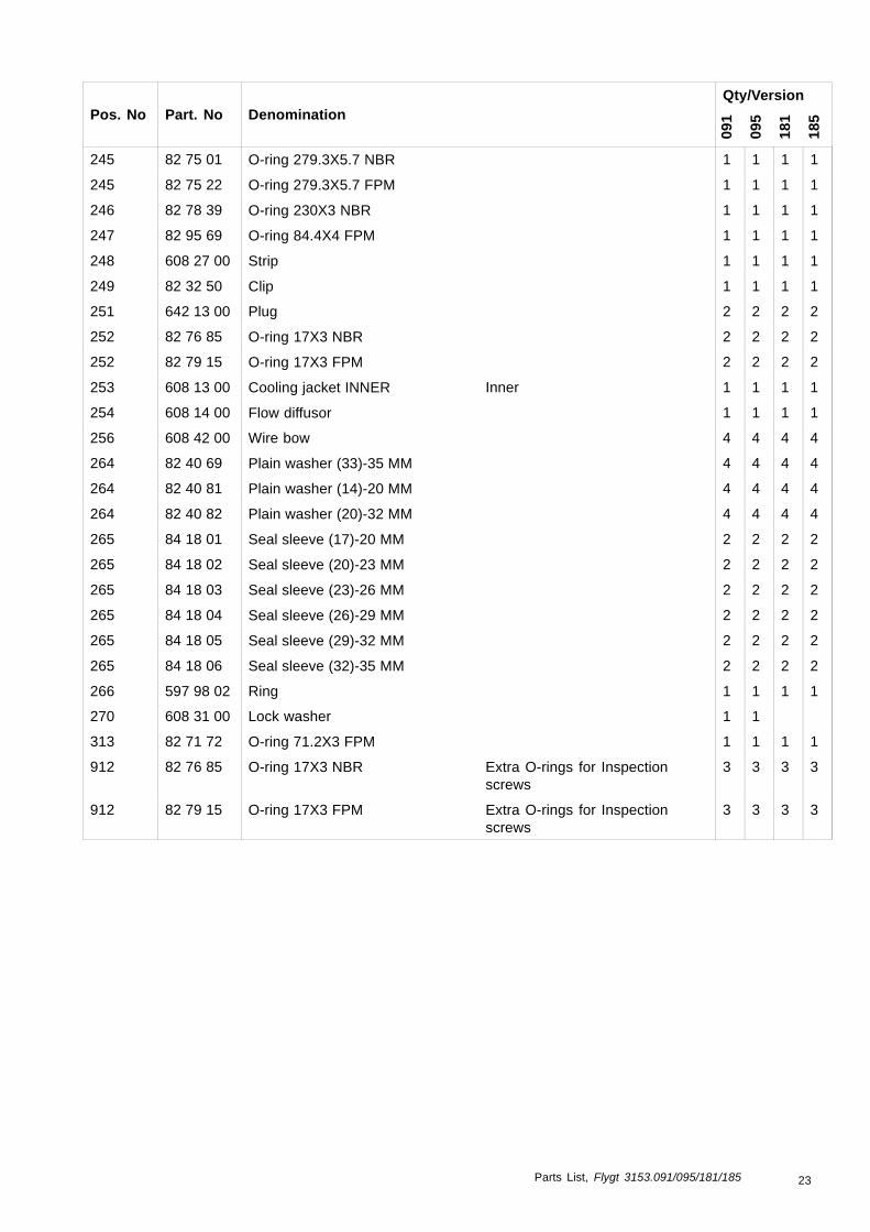
245 82 75 01 O-ring 279.3X5.7 NBR 1 1 1 1
245 82 75 22 O-ring 279.3X5.7 FPM 1 1 1 1
246 82 78 39 O-ring 230X3 NBR 1 1 1 1
247 82 95 69 O-ring 84.4X4 FPM 1 1 1 1
248 608 27 00 Strip 1 1 1 1
249 82 32 50 Clip 1 1 1 1
251 642 13 00 Plug 2 2 2 2
252 82 76 85 O-ring 17X3 NBR 2 2 2 2
252 82 79 15 O-ring 17X3 FPM 2 2 2 2
253 608 13 00 Cooling jacket INNER Inner 1 1 1 1
254 608 14 00 Flow diffusor 1 1 1 1
256 608 42 00 Wire bow 4 4 4 4
264 82 40 69 Plain washer (33)-35 MM 4 4 4 4
264 82 40 81 Plain washer (14)-20 MM 4 4 4 4
264 82 40 82 Plain washer (20)-32 MM 4 4 4 4
265 84 18 01 Seal sleeve (17)-20 MM 2 2 2 2
265 84 18 02 Seal sleeve (20)-23 MM 2 2 2 2
265 84 18 03 Seal sleeve (23)-26 MM 2 2 2 2
265 84 18 04 Seal sleeve (26)-29 MM 2 2 2 2
265 84 18 05 Seal sleeve (29)-32 MM 2 2 2 2
265 84 18 06 Seal sleeve (32)-35 MM 2 2 2 2
266 597 98 02 Ring 1 1 1 1
270 608 31 00 Lock washer 1 1
313 82 71 72 O-ring 71.2X3 FPM 1 1 1 1
912 82 76 85 O-ring 17X3 NBR Extra O-rings for Inspectionscrews
3 3 3 3
912 82 79 15 O-ring 17X3 FPM Extra O-rings for Inspectionscrews
3 3 3 3
Parts List, Flygt 3153.091/095/181/185 23

Hydraulic Parts
Overview
Table ofContents
This chapter contains the following topics:
Topic
N_ LT ................................................................................................................ 254–pole .......................................................................................................... 256–pole .......................................................................................................... 26
N_ MT ............................................................................................................... 27N_ HT ............................................................................................................... 28N_ SH ............................................................................................................... 29List.................................................................................................................... 30
24 Parts List, Flygt 3153.091/095/181/185

N_ LT
4–pole
“LT” low head. Curve: 410 – 416
267
Parts List, Flygt 3153.091/095/181/185 25

6–pole
“LT” low head. Curve: 620, 621, 622, 623, 624, 625
N_ 3153 LT (6-pole)
131
258
158267
193
186
145
162
169
200
200.4200.6
200.5
31364
163
26 Parts List, Flygt 3153.091/095/181/185

N_ MT
“MT” medium head. Curve: 430–437
267
Parts List, Flygt 3153.091/095/181/185 27

N_ HT
“HT” high head. Curve: 450, 451, 453–456, 461-466
267
28 Parts List, Flygt 3153.091/095/181/185

N_ SH
“SH” super high head. Curve: 270, 272-276
267
Parts List, Flygt 3153.091/095/181/185 29

List
Qty/VersionPos. No Part. No Denomination
091
095
181
185
131 82 75 01 O-ring 279.3X5.7 NBR 1 1 1 1
131 82 75 22 O-ring 279.3X5.7 FPM 1 1 1 1
153 681 28 00 Insert ring 1 1 1 1
158 605 94 00 Impeller "HT" High head. Curve no: 461,60 Hz, 3-phase
1 1
158 605 94 09 Impeller "HT" High head. Curve: 462, 60Hz, 3-phase
1 1
158 605 94 22 Impeller "HT" High head. Curve no: 463,60 Hz, 3-phase
1 1
158 605 94 32 Impeller "HT" High head. Curve no: 464,60 Hz, 3-phase
1 1
158 605 94 46 Impeller "HT" High head. Curve no: 465,60 Hz, 3-phase
1 1
158 605 94 55 Impeller "HT" High head. Curve no: 466,60 Hz, 3-phase
1 1
158 654 77 00 Impeller "LT" Low head. Curve no: 620, 50Hz, 3-phase
1 1
158 654 77 15 Impeller "LT" Low head. Curve no: 621, 50Hz, 3-phase
1 1
158 654 77 30 Impeller "LT" Low head. Curve no: 622,50/60 Hz, 3-phase
1 1
158 654 77 45 Impeller "LT" Low head. Curve no: 623,50/60 Hz, 3-phase
1 1
158 654 77 62 Impeller "LT" Low head. Curve no: 624,50/60 Hz, 3-phase
1 1
158 654 77 81 Impeller "LT" Low head. Curve no: 625,50/60 Hz, 3-phase
1 1
158 685 15 00 Impeller "SH" Super high head. Curve no:270, 50 Hz, 3-phase
1 1
158 685 15 18 Impeller "SH" Super high head. Curve no:272, 50 Hz, 3-phase
1 1
158 685 15 27 Impeller "SH" Super high head. Curve no:273, 50/60 Hz, 3-phase
1 1
158 685 15 39 Impeller "SH" Super high head. Curve no:274, 50/60 Hz, 3-phase
1 1
158 685 15 48 Impeller "SH" Super high head. Curve:275, 50/60 Hz, 3-phase
1 1
158 685 15 57 Impeller "SH" Super high head. Curve:276, 50/60 Hz, 3-phase
1 1
158 696 48 00 Impeller "HT" High head. Curve no: 450,50 Hz, 3-phase
1 1
158 696 48 14 Impeller "HT" High head. Curve no: 451,50 Hz, 3-phase
1 1
30 Parts List, Flygt 3153.091/095/181/185

Qty/VersionPos. No Part. No Denomination
09
1
09
5
18
1
18
5
158 696 48 28 Impeller "HT" High head. Curve no: 453,50/60 Hz, 3-phase.
1 1
158 696 48 39 Impeller "HT" High head. Curve no: 454,50 Hz, 3-phase.
1 1
158 696 48 50 Impeller "HT" High head. Curve no: 455,50 Hz, 3-phase.
1 1
158 696 48 60 Impeller "HT" High head. Curve no: 456,50 Hz, 3-phase.
1 1
158 696 49 00 Impeller "MT" Medium head. Curve no:430, 50 Hz, 3-phase
1 1
158 696 49 08 Impeller "MT" Medium head. Curve no:431, 50 Hz, 3-phase
1 1
158 696 49 20 Impeller "MT" Medium head. Curve no:432, 50 Hz, 3-phase
1 1
158 696 49 32 Impeller "MT" Medium head. Curve no:433, 50/60 Hz, 3-phase
1 1
158 696 49 42 Impeller "MT" Medium head. Curve no:434, 50/60 Hz, 3-phase
1 1
158 696 49 52 Impeller "MT" Medium head. Curve no:435, 50/60 Hz, 3-phase
1 1
158 696 49 65 Impeller "MT" Medium head. Curve no:436, 50/60 Hz, 3-phase
1 1
158 696 49 75 Impeller "MT" Medium head. Curve no:437, 60 Hz, 3-phase
1 1
158 696 50 00 Impeller "LT" Low head. Curve 410, 50 Hz,3-phase
1 1
158 696 50 10 Impeller "LT" Low head. Curve 411, 50 Hz,3-phase
1 1
158 696 50 22 Impeller "LT" Low head. Curve 412, 50 Hz,3-phase
1 1
158 696 50 33 Impeller "LT" Low head. Curve 413, 50/60Hz, 3-phase
1 1
158 696 50 43 Impeller "LT" Low head. Curve 414, 50/60Hz, 3-phase
1 1
158 696 50 57 Impeller "LT" Low head. Curve 415, 50/60Hz, 3-phase
1 1
158 696 50 63 Impeller "LT" Low head. Curve 416, 60 Hz,3-phase
1 1
158 698 71 14 Impeller "HT" High head. Curve 451, 50Hz, 3-phase
1 1
158 698 71 39 Impeller "HT" High head. Curve 454, 50Hz, 3-phase
1 1
158 698 72 08 Impeller "MT" Medium head. Curve: 431,50 Hz, 3-phase
1 1
158 698 72 42 Impeller "MT" Medium head. Curve: 434,50/60 Hz, 3-phase
1 1
Parts List, Flygt 3153.091/095/181/185 31

Qty/VersionPos. No Part. No Denomination
09
1
09
5
18
1
18
5
158 698 72 65 Impeller "MT" Medium head. Curve: 436,50/60 Hz, 3-phase
1 1
158 698 73 00 Impeller "LT" Low head. Curve: 410, 50Hz, 3-phase
1 1
158 698 73 33 Impeller "LT" Low head. Curve: 413, 50/60Hz, 3-phase
1 1
158 698 73 57 Impeller "LT" Low head. Curve: 415, 50/60Hz, 3-phase
1 1
158 699 26 18 Impeller "SH" Super high head. Curve:272, 50 Hz, 3-phase
1 1
158 699 26 39 Impeller "SH" Super high head. Curve:274, 50/60 Hz, 3-phase
1 1
158 699 26 57 Impeller "SH" Super hig head. Curve: 276,50/60 Hz, 3-phase, High Chrome
1 1
158 703 20 09 Impeller "HT" High head. Curve: 462, 60Hz, 3-phase
1 1
158 703 20 32 Impeller "HT" High head. Curve: 464, 60Hz, 3-phase
1 1
158 704 36 00 Impeller "LT" Low head. Curve: 620, 50Hz, 3-phase
1 1
158 704 36 30 Impeller "LT" Low head. Curve: 622, 50/60Hz, 3-phase
1 1
158 704 36 62 Impeller "LT" Low head. Curve: 624, 50/60Hz, 3-phase
1 1
162 82 38 00 Plain washer STAINLESS STEELA4
1 1 1 1
163 82 69 40 Protective plug 4 4 4 4
169 83 04 55 Hex.socket hd screwM12X110-A4-80
1 1 1 1
169 83 04 66 Hex.socket hd screwM12X80-A4-80
1 1 1 1
186 702 28 00 Insert ring "MT" version 091/181 1 1
186 702 29 00 Insert ring "MT" version 095/185 1 1
186 702 82 00 Insert ring "HT" version 091/181 1 1
186 702 83 00 Insert ring "HT" version 095/185 1 1
186 702 85 00 Insert ring "SH" version 091/181 1 1
186 702 85 01 Insert ring "SH" version 091/181, preparedfor guide pin
1 1
186 702 86 00 Insert ring "SH" version 095/185 1 1
186 702 86 01 Insert ring "SH" version 095/185, preparedfor guide pin
1 1
186 702 88 00 Insert ring "LT" 4-pole version 091/181 1 1
186 702 89 00 Insert ring "LT" 4-pole version 095/185 1 1
186 704 66 00 Insert ring "LT" 6-pole version 091/181 1 1
32 Parts List, Flygt 3153.091/095/181/185

Qty/VersionPos. No Part. No Denomination
09
1
09
5
18
1
18
5
186 704 67 00 Insert ring "LT" 6-pole version 095/185 1 1
193 82 00 60 Hex.socket hd screwM10X70-A2-70
3 3 3 3
193 83 04 56 Hex.socket hd screwM10X35-A4-80
3 3 3 3
200 702 27 00 Pump housing "MT" Medium head DN 150.Undrilled inlet, Prepared for Flushvalve
1 1 1 1
200 702 27 03 Pump housing "MT" Medium head DN 150.Drilled inlet, Prepared for zincanodes (only for P and S install.)Prepared for Flush valve
1 1 1 1
200 702 27 06 Pump housing "MT" Medium head. Drilled to:EN 1092-2 tab.9, ANSI B16.1-89;tab.5. Prepared for Flush valve
1 1 1 1
200 702 81 00 Pump housing "HT" High head DN 100. Undrilled,Prepared for Flush valve
1 1 1 1
200 702 81 01 Pump housing "HT" High head DN 100. Drilledto: EN 1092-2 tab.9. Prepared forFlush valve
1 1 1 1
200 702 81 03 Pump housing "HT" High head DN 100. Drilledinlet. Prepared for zinc anodes(only for P and S installation).Prepared for Flush valve
1 1 1 1
200 702 81 05 Pump housing "HT" High head DN 100. Drilled to:ANSI B16.1-89; tab.5. Preparedfor Flush valve
1 1 1 1
200 702 84 00 Pump housing "SH" Super high head DN 80. Withor without guide pin. Prepared forflush valve.
1 1 1 1
200 702 84 01 Pump housing "SH" Super high head DN 80.Drilled to: EN 1092-2 tab.9. Withor without guide pin. Prep. forflush valve
1 1 1 1
200 702 84 03 Pump housing "SH" Super high head DN 80.Drilled inlet. With or without guidepin. Prep. for flush valve and zincanodes. Only P or S
1 1 1 1
200 702 84 05 Pump housing "SH" Super high head DN 80.Drilled to: ANSI B16.1-89; tab.5.With or without guide pin. Prep.for flush valve
1 1 1 1
200 702 84 10 Pump housing "SH" Super high head DN 80.Pumphousing with outlet sealing.With or without guide pin. Prep.for flush valve.
1 1 1 1
200 702 84 13 Pump housing "SH" Super high head DN 80.Drilled inlet. With outlet sealing.Prep for zinc anodes and flushvalve. P or S install.
1 1 1 1
Parts List, Flygt 3153.091/095/181/185 33

Qty/VersionPos. No Part. No Denomination
09
1
09
5
18
1
18
5
200 702 84 20 Pump housing "SH" Super high head DN 100.With outlet sealing. With or withoutguide pin. Prep. for Flush valve.
1 1 1 1
200 702 84 23 Pump housing "SH" Super high head DN 100. Dr.inlet. With oulet sealing. With orwithout guide pin. Prep for f. valveand z. anodes.
1 1 1 1
200 702 87 00 Pump housing "LT" Low head DN 200. Undrilledinlet. Prepared for Flush valve.
1 1 1 1
200 702 87 03 Pump housing "LT" Low head DN 200. Drilledinlet. Prepared for zinc anodes(only for P and S installation).Prepared for Flush valve
1 1 1 1
200 702 87 06 Pump housing "LT" Low head DN 200. Drilled to:EN 1092-2 tab.8, ANSI B16.1-89;tab.5. Prepared for Flush valve.
1 1 1 1
200 702 87 07 Pump housing "LT" Low head DN 200. Drilledto: EN 1092-2 tab.9. Prepared forFlush valve.
1 1 1 1
200 704 65 00 Pump housing "LT" Low head DN 250. Undrilled.Prepared for flush valve.
1 1 1 1
200 704 65 01 Pump housing "LT" Low head DN 250. Drilledto EN 1092-2 tab.8. Prepared forflush valve.
1 1 1 1
200 704 65 03 Pump housing "LT" Low head DN 250. Drilled forS, T, Z and zinc anodes. Preparedfor flush valve.
1 1 1 1
200 704 65 05 Pump housing "LT" Low head DN 250. Drilled toANSI B16.1-89; tab.5. Preparedfor flush valve.
1 1 1 1
200 704 65 07 Pump housing "LT" Low head DN 250. Drilledto EN 1092-2 tab.9. Prepared forflush valve.
1 1 1 1
200.3 84 90 93 Seal ring Intended for pumphousing7028410, 7028413
1 1 1 1
200.3 84 90 94 Seal ring Intended for pumphousing7028420, 7028423
1 1 1 1
200.4 83 04 56 Hex.socket hd screwM10X35-A4-80
2 2 2 2
200.5 82 81 93 O-ring 44,2X5,7 FPM 1 1 1 1
200.6 648 00 00 Cover 1 1 1 1
258 720 14 00 Sleeve unit 1 1 1 1
267 725 06 00 Plug 3 3 3 3
271 703 22 00 Lip 1 1 1 1
273 83 04 56 Hex.socket hd screwM10X35-A4-80
1 1 1 1
275 679 01 01 Counter weight 1 1 1 1
34 Parts List, Flygt 3153.091/095/181/185

Qty/VersionPos. No Part. No Denomination
09
1
09
5
18
1
18
5
276 82 01 07 Hex.socket hd screwM16X50-A2-70
4 4 4 4
277 82 23 33 Hexagon nut M10-A4-70 1 1 1 1
Parts List, Flygt 3153.091/095/181/185 35

Sump Components
Overview
Table ofContents
This chapter contains the following topics:
Topic
NP .................................................................................................................... 37Discharge Connection ................................................................................... 37Hydroejector ................................................................................................. 38
NS ................................................................................................................... 39Hose ............................................................................................................ 39Quick Coupling.............................................................................................. 40
NT LT ................................................................................................................ 41NT MT/HT/SH.................................................................................................... 42NZ..................................................................................................................... 43List.................................................................................................................... 44
36 Parts List, Flygt 3153.091/095/181/185

NP
Discharge Connection
Parts List, Flygt 3153.091/095/181/185 37

Hydroejector
38 Parts List, Flygt 3153.091/095/181/185

NS
Hose
216
211
212
213215
219218217
30783
NS 3153
Parts List, Flygt 3153.091/095/181/185 39

Quick Coupling
NS 3153
30792
215213
212
216
211 218219
217
227
40 Parts List, Flygt 3153.091/095/181/185

NT LT
NT 3153
30793
220220.3220.2 220220.1
219218
221
217
Parts List, Flygt 3153.091/095/181/185 41

NT MT/HT/SH
42 Parts List, Flygt 3153.091/095/181/185

NZ
����
�
�����
��
���
Parts List, Flygt 3153.091/095/181/185 43

List
Qty/VersionPos. No Part. No Denomination
091
095
181
185
209 651 07 01 Sliding bracket 1 1 1 1
210 83 04 53 Hex.socket hd screwM12X45-A4-80
4 4 4 4
211 259 82 04 Discharge connection "HT/SH" Super/High head versionDN 100 (4")
1 1 1 1
211 259 84 05 Discharge connection "HT/SH" Super/High head versionDN 100 (4") Threaded 4-8 NPSMOuter
1 1 1 1
211 259 84 06 Discharge connection "HT" High head version DN 100(4"), Thread : ISO G4A Outer
1 1 1 1
211 281 79 00 Discharge connection "LT" Low head version DN 200 (8") 1 1 1 1
211 295 57 00 Discharge connection "MT" Medium head version DN150 (6")
1 1 1 1
211 309 31 00 Discharge connection "MT" Medium head version DN150 (6") Threaded 6-8 NPSMOuter
1 1 1 1
211 309 31 01 Discharge connection "MT" Medium head version DN150 (R6") Thread : ISO G6AOuter. Quick coupling: Storz
1 1 1 1
211 310 03 01 Discharge connection "SH" Super high head version DN75
1 1 1 1
211 379 32 00 Discharge connection "LT" Low head version DN 200 (8") 1 1 1 1
211 385 52 03 Discharge connection 3-8 NPSM "SH" Super high head version DN75 Threaded:3-8 NPSM Outer
1 1 1 1
211 385 52 04 Discharge connection ISO G3 "SH" Super high head version DN75 Threaded:ISO G3 Outer
1 1 1 1
211 479 26 00 Discharge connection "LT" Low head version DN 250(10")
1 1 1 1
212 81 49 36 Hexagon head screwM16X65-A4-70
4 4 4 4
212 84 34 07 Hexagon head screwM16X60-A2-70
Intended for, S -version "HT" 4 4 4 4
212 84 34 32 Hexagon head screwM20X70-A2-70
S-version "MT" 8 8 8 8
212 84 34 34 Hexagon head screwM20X80-A2-70
S-version "LT" 12 12 12 12
213 82 35 23 Plain washer 16-A2-A-170 8 8 4 4
213 82 35 26 Plain washer 20-A2-A-170 8 8 8 8
215 82 23 61 Hexagon nut M16-A2-70 4 4 4 4
215 82 23 62 Hexagon nut M20-A2-70 12 12 12 12
216 259 83 00 Gasket 4" 1 1 1 1
216 283 19 00 Gasket 8" 1 1 1 1
216 295 64 00 Gasket 6" 1 1 1 1
44 Parts List, Flygt 3153.091/095/181/185

Qty/VersionPos. No Part. No Denomination
09
1
09
5
18
1
18
5
216 310 05 00 Gasket Intended for "SH" 1 1 1 1
216 384 45 00 Gasket 8" 1 1 1 1
217 380 92 01 Stand compl. S/T-installation LT, DN 250 1 1 1 1
217 380 92 02 Stand compl. S-installation LT DN, 200/250,T-installation LT DN 300
1 1 1 1
217 396 11 00 Stand compl. S-installation MT, DN 150, HT/SH,DN 100, SH, DN 75. T-installationMT, DN 200, HT/SH, DN 150
1 1 1 1
217 608 23 02 Stand 1 1 1 1
218 81 43 73 Hexagon head screwM20X100-A2-70
T-version "LT" 12 12 12 12
218 84 34 03 Hexagon head screwM16X40-A2-70
T-version"MT", "HT", "SH",S-version "MT", "HT", "SH"
4 4 4 4
218 84 34 28 Hexagon head screwM20X50-A2-70 (ONLY TRSP)
T/S-version "LT" 4 4 4 4
218 84 34 32 Hexagon head screwM20X70-A2-70
4 4 4 4
218 84 34 34 Hexagon head screwM20X80-A2-70
T/S-version "LT" 4 4 4 4
219 82 35 23 Plain washer 16-A2-A-170 4
219 82 35 26 Plain washer 20-A2-A-170 12 12 12 12
219 82 38 01 Plain washer STAINLESS STEELA4
4 4 4 4
220 272 82 20 Suction pipe unit "SH" Super high head DN200. 1 1 1 1
220 272 82 26 Suction pipe unit "SH" Super high head DN200. 1 1 1 1
220 272 82 27 Suction pipe unit "SH" Super high head DN200. 1 1 1 1
220 295 60 20 Suction pipe unit "HT/SH" Super High head versionDN 150 (6"). Undrilled
1 1 1 1
220 295 60 26 Suction pipe unit "HT/SH" Super/ High head versionDN 150 (6"). Drilled to EN 1092-2tab.9, ANSI B16.1-89; tab.5
1 1 1 1
220 381 77 30 Suction connect.unit "MT/HT" Medium/High headDN250.
1 1 1 1
220 381 77 31 Suction pipe unit "MT/HT" Medium/High headDN250. Drilled to EN1092-2 tab.8.
1 1 1 1
220 381 77 35 Suction pipe unit "MT/HT" Medium/High headDN250. Drilled to ANSI B16.1-89;tab.5.
1 1 1 1
220 381 77 37 Suction pipe unit "MT/HT" Medium/High headDN250. Drilled to EN1092-2 tab.9.
1 1 1 1
220 384 74 00 Suction connect.unit "MT" Medium head DN300. 1 1 1 1
220 384 74 01 Suction pipe unit "MT" Medium head DN300. Drilledto EN1092-2 tab.8.
1 1 1 1
220 384 74 05 Suction pipe unit "MT" Medium head DN300. Drilledto ANSI B16.1-89; tab.5.
1 1 1 1
Parts List, Flygt 3153.091/095/181/185 45

Qty/VersionPos. No Part. No Denomination
09
1
09
5
18
1
18
5
220 384 74 07 Suction pipe unit "MT" Medium head DN300. Drilledto EN1092-2 tab.9.
1 1 1 1
220.1 81 41 56 Hexagon head screwM12X35-A2-70
Intended for 3817730, 31, 35, 37;3847400, 01, 05, 07.
4 4 4 4
220.1 81 52 17 Hexagon head screw 1/2UNCX32-A2-70
(SH, HT) DN 150 4 4 4 4
220.1 81 52 49 Hexagon head screw U6S 3/4 UNCX32-A2-70 4 4 4 4
220.2 274 45 00 Cleaning door Intended for 2728220, 26 ,27. 1 1 1 1
220.2 274 45 01 Cleaning door Intended for 3817730, 31, 35, 37,3847400, 01, 05, 07.
1 1 1 1
220.2 295 53 00 Cleaning door (SH, HT) DN 150 1 1 1 1
220.3 274 48 00 Gasket (MT, LT) DN 200/250/300 1 1 1 1
220.3 295 54 00 Gasket (SH, HT) DN 150 1 1 1 1
221 84 65 82 Gasket 250 PN 10 2 2 2 2
221 84 65 87 Gasket 150 PN10 1 1 1 1
221 84 65 88 Gasket 200 PN10 2 2 2 2
221 84 65 93 Gasket 125 PN10 1 1 1 1
222 81 41 81 Hexagon head screwM16X40-A4-70
4 4 4 4
222 81 49 56 Hexagon head screwM20X50-A4-70
4 4 4 4
222 81 55 40 Hexagon head screw M16X50A4-70
4 4 4 4
222 84 34 05 Hexagon head screwM16X50-A2-70
4 4 4 4
222 84 34 07 Hexagon head screwM16X60-A2-70
4 4 4 4
222 84 34 32 Hexagon head screwM20X70-A2-70
12 12 12 12
227 83 19 33 Coupling part DN 100 G4" INNERSTORZ
1 1
227 83 19 34 Coupling part DN 110 G4" INNERSTORZ
1 1 1 1
227 83 19 36 Coupling part DN 150 G6B INNERSTORZ
1 1 1 1
46 Parts List, Flygt 3153.091/095/181/185

Parts for Service
Parts List, Flygt 3153.091/095/181/185 47

List
Qty/VersionPos. No Part. No Denomination
091
095
181
185
800 84 15 47 O-ring kit INTERMEDIATESERVICE KIT
NBR O-rings < = 70 DEGR.C 1 1 1 1
800 84 15 48 O-ring kit INTERMEDIATESERVICE KIT
FPM O-rings , Industry 1 1 1 1
900 657 17 08 Basic repair kit NBR O-rings < = 70 DEGR.CDEGR.C. Standard. Incl.Mechanical Seal WCCR/WCCR
1 1 1 1
900 657 17 09 Basic repair kit Warm water. Incl. 641 50 00Mechanical Seal WCCR/WCCR
1 1 1 1
900 657 17 10 Basic repair kit NBR O-rings < = 70 DEGR.C. Incl.Mechanical Seal WCCR/RSiC
1 1 1 1
900 657 17 11 Basic repair kit FPM O-rings Industry. Incl.Mechanical Seal WCCR/RSiC
1 1 1 1
901 90 37 08 Monopropylene glycol "DOWCALN"
* * * *
48 Parts List, Flygt 3153.091/095/181/185


What can ITT Water & Wastewater do for you?
Integrated solutions for fluid handling are offered by ITT Water & Wastewater as a world leader in trans-
port and treatment of wastewater. We provide a complete range of water, wastewater and drainage
pumps, equipment for monitoring and control, units for primary and secondary biological treatment,
products for filtration and disinfection, and related services. ITT Water & Wastewater, headquartered in
Sweden, operates in some 140 countries across the world, with own plants in Europe, China and North
and South America. The company is wholly owned by the ITT Corporation of White Plains, New York,
supplier of advanced technology products and services.
Visit our Web site for the latest version of this document and more informationwebservices.ittwww.com/tpi
ITT Water & Wastewater ABSE-174 87 SundbybergSweden
Visiting address:Gesällvägen 33SundbybergSweden
Tel. +46–8–475 60 00Fax +46–8–475 69 00
© ITT Water & Wastewater AB. The original instruction is in English.All non-English instructions are translations of the original instruction.
896676_7.0_en.US_2011–05_GPL.3153