XTRAFIX External Fixation System
28
XTRAFIX ® External Fixation System Surgical Technique
Transcript of XTRAFIX External Fixation System
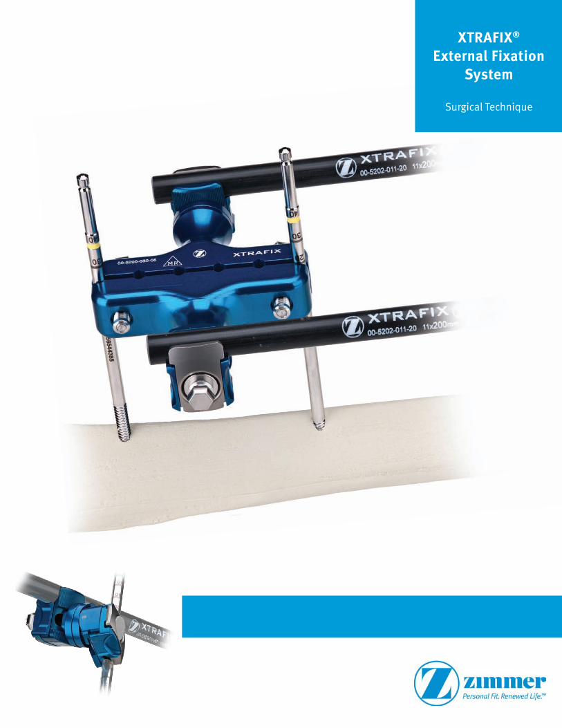
XTRAFIX® External Fixation
System
Surgical Technique
2 XTRAFIX® External Fixation System – Surgical Technique
XTRAFIX External Fixation System Surgical Technique
Item List ..............................................................................................................................4
Bar/Pin Tray .....................................................................................................................4
Clamp Tray .......................................................................................................................5
XTRAFIX Trays .....................................................................................................................6
Surgical Technique...............................................................................................................8
Choose Pin Size ...............................................................................................................8
Select Trocar and Tissue Protector ....................................................................................9
Securing Tissue Protector ..............................................................................................10
Remove Trocar and Insert Drill (Optional) .......................................................................11
Remove Trocar (or Drill) and Insert Pin ............................................................................12
Attaching Clamps to Pins ...............................................................................................13
Attaching Bars ...............................................................................................................15
Attaching Posts to Multi-Pin Clamps (Optional) ..............................................................16
Removing Bars ..............................................................................................................18
Efficiency Multi-Pin Clamps ...............................................................................................20
45mm, 2-Bar, Multi-Pin Efficiency Clamp .......................................................................20
75mm, 2-Bar, Multi-Pin Efficiency Clamp .......................................................................21
45mm, 1-Bar Pin Clamp .................................................................................................22
Sample Constructs .............................................................................................................23
Pin-to-Bar ......................................................................................................................23
Tibial Frame ...................................................................................................................24
Knee-Spanning ..............................................................................................................24
Ankle-Spanning .............................................................................................................25
Pelvic ............................................................................................................................27
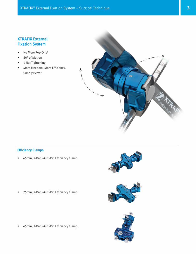
3XTRAFIX® External Fixation System – Surgical Technique
Efficiency Clamps
• 45mm, 2-Bar, Multi-Pin Efficiency Clamp
• 75mm, 2-Bar, Multi-Pin Efficiency Clamp
• 45mm, 1-Bar, Multi-Pin Efficiency Clamp
XTRAFIX External Fixation System
• No More Pop-Offs1
• 80° of Motion
• 1 Nut Tightening
• More Freedom, More Efficiency,
Simply Better

4 XTRAFIX® External Fixation System – Surgical Technique
Item # BAR/PIN TRAY
00-5202-011-10 11mm Bar X 100mm
00-5202-011-15 11mm Bar X 150mm
00-5202-011-20 11mm Bar X 200mm
00-5202-011-25 11mm Bar X 250mm
00-5202-011-30 11mm Bar X 300mm
00-5202-011-35 11mm Bar X 350mm
00-5202-011-40 11mm Bar X 400mm
00-5202-011-50 11mm Bar X 500mm
00-5202-011-60 11mm Bar X 600mm*
00-5202-010-18 11mm Bent Bar 175mm
00-5202-090-00 Straight Post, 11mm
00-5202-090-30 30° Angled Post, 11mm
00-5202-090-90 90° Angled Post, 11mm
00-5202-020-21 Curved Bar 210mm
00-5202-020-38 Curved Bar 380mm
00-5202-020-50 Curved Bar 500mm
00-5210-009-02 T-Handle AO Locking/9mm
00-5210-040-00 Tissue Protector Handle
*Optional Items
Item List
Bar/Pin Tray
ITEM # BAR/PIN TRAY
00-5207-024-30 Blue 2.4mm Drill
00-5207-032-30 Blue 3.2mm Drill
00-5207-040-70 Yellow 4.0mm Drill Medium
00-5207-040-10 Orange 4.0mm Drill Long
00-5207-045-10 Green 4.5mm Drill
00-5210-040-01 Blue Short Tissue Protector
00-5210-050-01 Blue Short Trocar
00-5210-040-02 Yellow Medium Tissue Protector
00-5210-050-02 Yellow Medium Trocar
00-5210-040-03 Orange Long Tissue Protector
00-5210-050-03 Orange Long Trocar
00-5210-040-06 Green 6mm Tissue Protector
00-5210-050-06 Green 6mm Trocar
00-5210-040-04 Black Transfixing Pin Tissue Protector
00-5210-050-04 Black Transfixing Pin Trocar
00-5204-030-25 Blue 3mm x 100mm x 25mm Half Pin
00-5204-030-15 Blue 3mm x 100mm x 15mm Half Pin
00-5204-040-35 Blue 4mm x 100mm x 35mm Half Pin
00-5204-040-20 Blue 4mm x 100mm x 20mm Half Pin
00-5204-050-35 Yellow 5mm x 160mm x 35mm Half Pin
00-5204-050-55 Yellow 5mm x 160mm x 55mm Half Pin
00-5204-050-45 Orange 5mm x 200mm x 45mm Half Pin
00-5204-050-65 Orange 5mm x 200mm x 65mm Half Pin
00-5204-050-85 Orange 5mm x 250mm x 85mm Half Pin
00-5204-090-28 Black Transfixing 5mm x 275mm, 6mm Thread Pin
00-5204-060-55 Green 6mm x 200mm x 55mm Half Pin

5XTRAFIX® External Fixation System – Surgical Technique
ITEM # CLAMP TRAY
00-5200-010-01 Bar to Bar Clamp 3-D
00-5200-010-02 Bar to Pin Clamp 3-D
00-5200-040-04 45mm Pin Clamp
00-5200-040-08 105mm Pin Clamp
00-5200-020-04 45mm Pin Clamp, 1-Bar
00-5200-030-04 45mm Pin Clamp, 2-Bar
00-5200-030-06 75mm Pin Clamp, 2-Bar
00-5210-009-01 T-Handle 9mm
00-5210-019-01 9mm Open/Box End Wrench
00-5210-029-01 9mm Ratchet Wrench
00-5210-039-01 9mm Thumbwheel
Item List
Clamp Tray
Item # OPTIONAL ITEMS
00-5200-090-01 Bar to Bar Clamp 2-D No Motion
00-5200-090-02 Bar to Pin Clamp 2-D No Motion
00-5200-050-04 K-Rod 45mm Pin Clamp, 2-Bar
00-5205-030-15 Blue 3mm x 100mm x 15mm Blunt Half Pin
00-5205-040-20 Blue 4mm x 100mm x 20mm Blunt Half Pin
00-5205-050-30 Yellow 5mm x 120mm x 30mm Blunt Half Pin
00-5205-050-35 Yellow 5mm x 160mm x 35mm Blunt Half Pin
00-5205-050-55 Yellow 5mm x 160mm x 55mm Blunt Half Pin
00-5205-050-45 Orange 5mm x 200mm x 45mm Blunt Half Pin
00-5205-050-65 Orange 5mm x 200mm x 65mm Blunt Half Pin
00-5203-011-07 11mm Carbon Bar 65mm*
00-5203-011-10 11mm Carbon Bar 100mm
00-5203-011-15 11mm Carbon Bar 150mm
00-5203-011-20 11mm Carbon Bar 200mm
00-5203-011-25 11mm Carbon Bar 250mm
00-5203-011-30 11mm Carbon Bar 300mm
00-5203-011-35 11mm Carbon Bar 350mm
00-5203-011-40 11mm Carbon Bar 400mm
00-5203-011-50 11mm Carbon Bar 500mm
00-5203-011-60 11mm Carbon Bar 600mm
00-5203-020-18 11mm Carbon Bent Bar 175
00-5203-020-21 11mm Carbon Curved Bar, 210mm
00-5203-020-38 11mm Carbon Curved Bar, 380mm
00-5203-020-50 11mm Carbon Curved Bar, 500mm

6 XTRAFIX® External Fixation System – Surgical Technique
XTRAFIX Trays
A Complete, Efficient Set in Two Simple Trays
1. Clamp Tray
2. Bar/Pin Tray
7XTRAFIX® External Fixation System – Surgical Technique
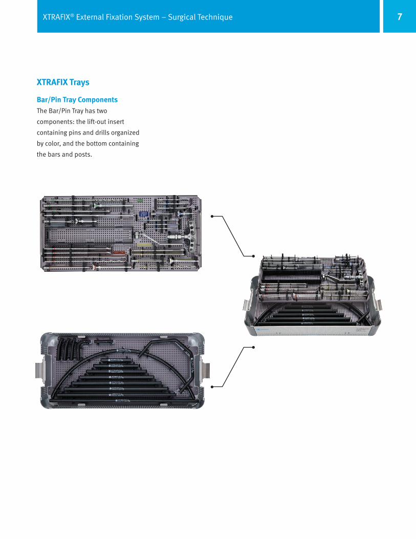
XTRAFIX Trays
Bar/Pin Tray ComponentsThe Bar/Pin Tray has two
components: the lift-out insert
containing pins and drills organized
by color, and the bottom containing
the bars and posts.
8 XTRAFIX® External Fixation System – Surgical Technique
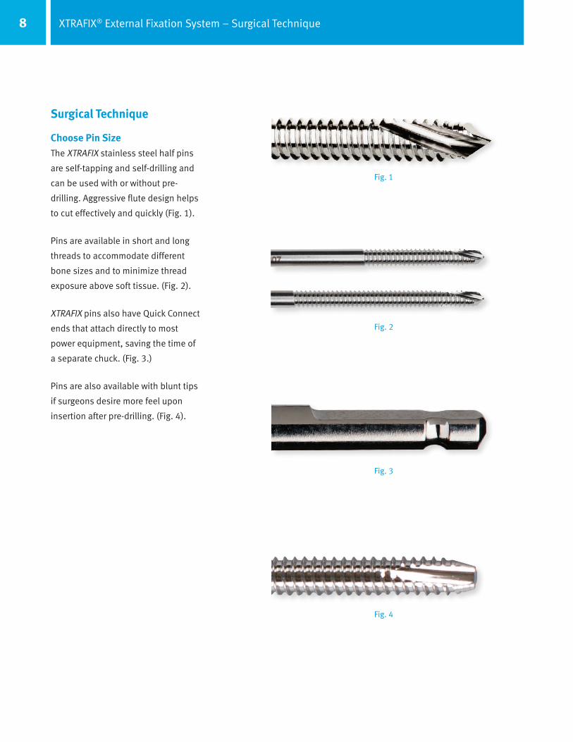
Surgical Technique
Choose Pin SizeThe XTRAFIX stainless steel half pins
are self-tapping and self-drilling and
can be used with or without pre-
drilling. Aggressive flute design helps
to cut effectively and quickly (Fig. 1).
Pins are available in short and long
threads to accommodate different
bone sizes and to minimize thread
exposure above soft tissue. (Fig. 2).
XTRAFIX pins also have Quick Connect
ends that attach directly to most
power equipment, saving the time of
a separate chuck. (Fig. 3.)
Pins are also available with blunt tips
if surgeons desire more feel upon
insertion after pre-drilling. (Fig. 4).
Fig. 1
Fig. 2
Fig. 3
Fig. 4
9XTRAFIX® External Fixation System – Surgical Technique
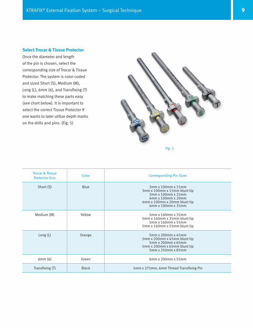
Select Trocar & Tissue ProtectorOnce the diameter and length
of the pin is chosen, select the
corresponding size of Trocar & Tissue
Protector. The system is color-coded
and sized Short (S), Medium (M),
Long (L), 6mm (6), and Transfixing (T)
to make matching these parts easy
(see chart below). It is important to
select the correct Tissue Protector if
one wants to later utilize depth marks
on the drills and pins. (Fig. 5)
Fig. 5
Trocar & Tissue Protector Size
Color Corresponding Pin Sizes
Short (S) Blue 3mm x 100mm x 15mm3mm x 100mm x 15mm blunt tip
3mm x 100mm x 25mm4mm x 100mm x 20mm
4mm x 100mm x 20mm blunt tip4mm x 100mm x 35mm
Medium (M) Yellow 5mm x 160mm x 35mm5mm x 160mm x 35mm blunt tip
5mm x 160mm x 55mm5mm x 160mm x 55mm blunt tip
Long (L) Orange 5mm x 200mm x 45mm5mm x 200mm x 45mm blunt tip
5mm x 200mm x 65mm5mm x 200mm x 65mm blunt tip
5mm x 250mm x 85mm
6mm (6) Green 6mm x 200mm x 55mm
Transfixing (T) Black 5mm x 275mm, 6mm Thread Transfixing Pin

10 XTRAFIX® External Fixation System – Surgical Technique
Tissue Protector in Tissue Protector Handle
Tissue Protectors in Multi-Pin Clamp
Locked Unlocked
Securing Tissue ProtectorsTissue Protectors will lock directly
into Multi-Pin Clamps or into the
Tissue Protector Handle (for simple
bar-to-pin constructs). This allows
surgeons to quickly and easily
anchor Protectors against the
bone. Lock the Tissue Protector
into the Multi-Pin Clamp or Tissue
Protector Handle by pressing
down and turning 90°. Insert the
corresponding Trocar through the
Tissue Protector, and then insert the
assembly through the soft tissue
and against the bone (Fig. 6).
The bottom end of each Tissue
Protector has a toothed edge to help
stabilize the assembly on the bone
(Fig. 6).
Note: Tissue Protectors may also be
left in the unlocked position if the
height needs to vary between the
first and second Tissue Protector
(Fig. 7).
Fig. 6
Fig. 7
11XTRAFIX® External Fixation System – Surgical Technique
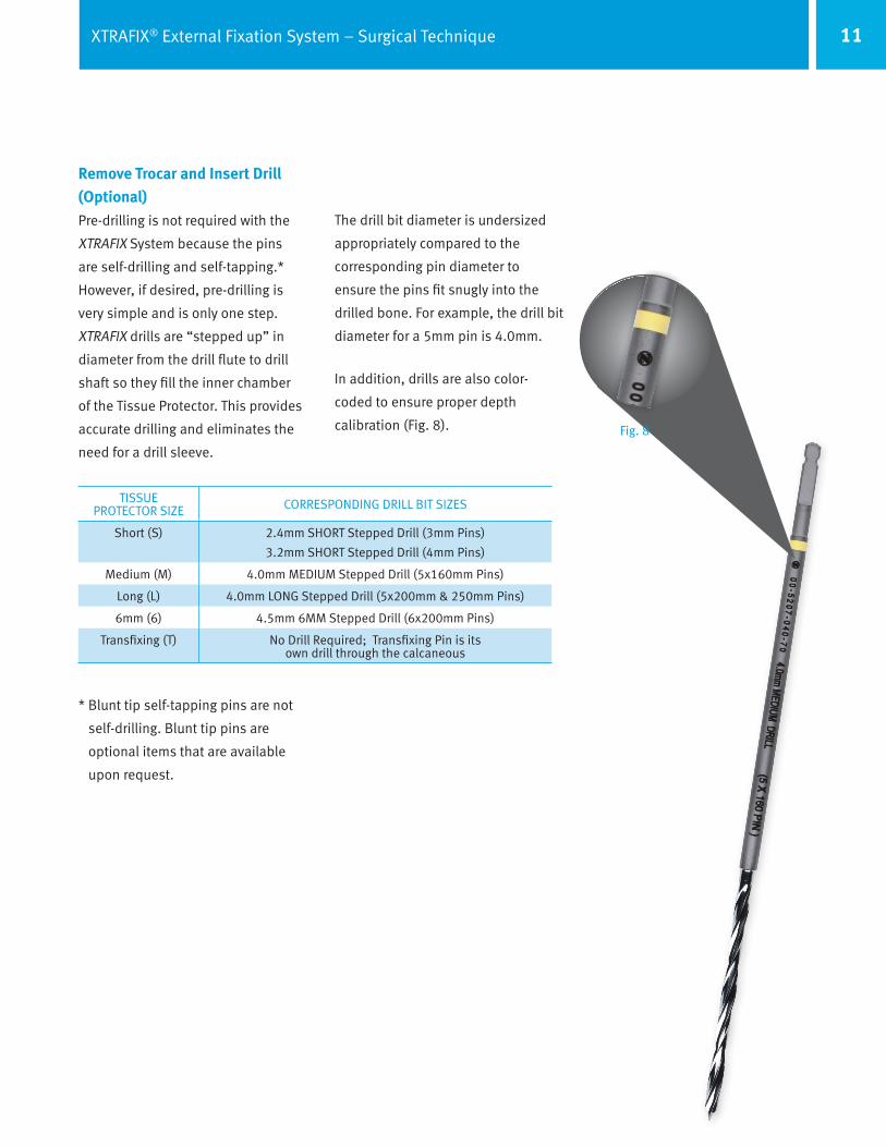
TISSUE PROTECTOR SIZE CORRESPONDING DRILL BIT SIZES
Short (S) 2.4mm SHORT Stepped Drill (3mm Pins)
3.2mm SHORT Stepped Drill (4mm Pins)
Medium (M) 4.0mm MEDIUM Stepped Drill (5x160mm Pins)
Long (L) 4.0mm LONG Stepped Drill (5x200mm & 250mm Pins)
6mm (6) 4.5mm 6MM Stepped Drill (6x200mm Pins)
Transfixing (T) No Drill Required; Transfixing Pin is its own drill through the calcaneous
* Blunt tip self-tapping pins are not
self-drilling. Blunt tip pins are
optional items that are available
upon request.
Remove Trocar and Insert Drill (Optional)Pre-drilling is not required with the
XTRAFIX System because the pins
are self-drilling and self-tapping.*
However, if desired, pre-drilling is
very simple and is only one step.
XTRAFIX drills are “stepped up” in
diameter from the drill flute to drill
shaft so they fill the inner chamber
of the Tissue Protector. This provides
accurate drilling and eliminates the
need for a drill sleeve.
The drill bit diameter is undersized
appropriately compared to the
corresponding pin diameter to
ensure the pins fit snugly into the
drilled bone. For example, the drill bit
diameter for a 5mm pin is 4.0mm.
In addition, drills are also color-
coded to ensure proper depth
calibration (Fig. 8). Fig. 8
12 XTRAFIX® External Fixation System – Surgical Technique
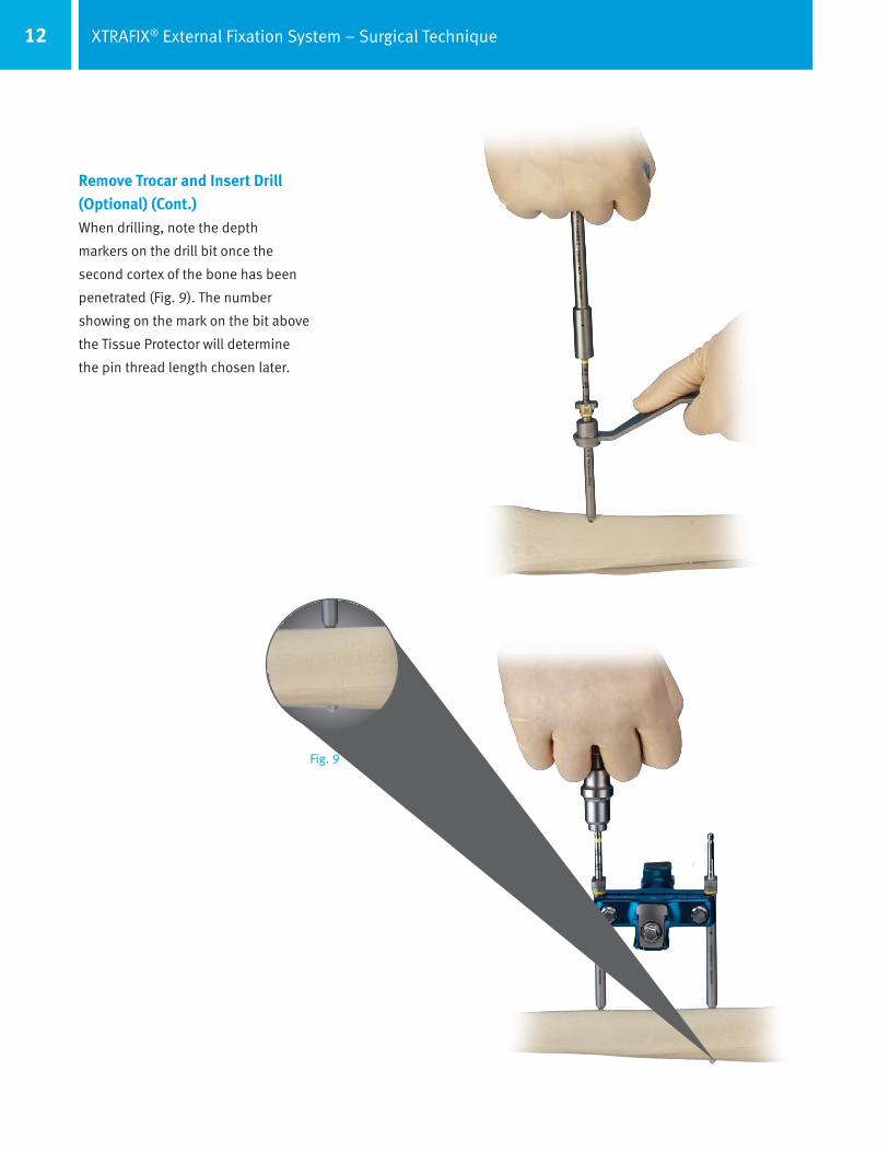
Remove Trocar and Insert Drill (Optional) (Cont.)When drilling, note the depth
markers on the drill bit once the
second cortex of the bone has been
penetrated (Fig. 9). The number
showing on the mark on the bit above
the Tissue Protector will determine
the pin thread length chosen later.
Fig. 9

13XTRAFIX® External Fixation System – Surgical Technique
Remove Trocar (or Drill) and Insert PinOnce the drilling is complete, dispose
of the drill bit used and select the
appropriate pin. As mentioned
earlier, the XTRAFIX pins attach
directly to most power equipment.
However, if one wishes to insert the
pin without a drill, use the T-Handle
9mm/AO Wrench. It is a combination
tool that tightens and loosens pins
and clamp nuts.
Slide the top of the pin into the
base of the T-Handle and rotate
the wrench until it locks in place.
The pin will give tactile and audible
feedback that it has fit into the AO
channel of the wrench. If using the
shorter “locking” T-Handle, pull
up on the base of the shaft, rotate
the wrench until the pin locks in
place. Release the base to lock the
pin into the wrench. This allows for
additional manual manipulation and
joystick-like movements.
Once the pin is secure, proceed by
inserting the pin into the Tissue
Protector. Note, the pin has the same
depth marks as its corresponding
drill (Fig. 10). The number shown
on the pin at the top of the
Tissue Protector is the number of
millimeters the pin is protruding from
the bottom of the Tissue Protector
and into the bone.
If one has previously pre-drilled,
simply insert the pin to the same
depth mark as was used with the drill
bit. This saves time and may reduce
fluoro exposure.
Fig. 10
14 XTRAFIX® External Fixation System – Surgical Technique
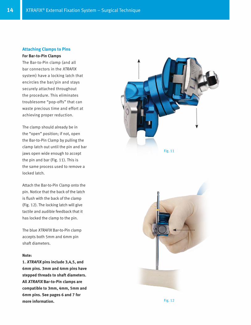
Attaching Clamps to PinsFor Bar-to-Pin Clamps
The Bar-to-Pin clamp (and all
bar connectors in the XTRAFIX
system) have a locking latch that
encircles the bar/pin and stays
securely attached throughout
the procedure. This eliminates
troublesome “pop-offs” that can
waste precious time and effort at
achieving proper reduction.
The clamp should already be in
the “open” position; if not, open
the Bar-to-Pin Clamp by pulling the
clamp latch out until the pin and bar
jaws open wide enough to accept
the pin and bar (Fig. 11). This is
the same process used to remove a
locked latch.
Attach the Bar-to-Pin Clamp onto the
pin. Notice that the back of the latch
is flush with the back of the clamp
(Fig. 12). The locking latch will give
tactile and audible feedback that it
has locked the clamp to the pin.
The blue XTRAFIX Bar-to-Pin clamp
accepts both 5mm and 6mm pin
shaft diameters.
Note:
1. XTRAFIX pins include 3,4,5, and
6mm pins. 3mm and 4mm pins have
stepped threads to shaft diameters.
All XTRAFIX Bar-to-Pin clamps are
compatible to 3mm, 4mm, 5mm and
6mm pins. See pages 6 and 7 for
more information. Fig. 12
Fig. 11

15XTRAFIX® External Fixation System – Surgical Technique
Attaching Clamps to PinsFor Multi-Pin Clamps
After the pins are inserted through
Multi-Pin Clamps, turn the Tissue
Protectors 90° to unlock. Remove the
Tissue Protectors by pulling straight
up, leaving the Multi-Pin Clamp to
grab onto the pin (Fig. 13).
Then secure the Multi-Pin Clamp to
the pins by tightening the two nuts
on the outside of the clamp (Fig. 14).
Notes:
1. The 75mm Pin Clamp, 2-Bar
needs to be tightened to the pins
and bars independently. The
75mm Pin Clamp, 2-Bar differs
from the 45mm Pin Clamp, 2-Bar
as it is not a one nut tightening
clamp.
2. The 45mm Pin Clamp, 2-Bar does
not need to be tightened to the
pins, as one nut tightens the
clamp to bars and pins.
Fig. 13
Fig. 14

16 XTRAFIX® External Fixation System – Surgical Technique
Attaching BarsThe technique for attaching bars to
clamps is identical to the process for
attaching pins. It is also the process
for attaching clamps to posts. Simply
insert the bar and pinch the bar and
the back side of the latch together to
lock the jaws (Fig. 15).
The bar and pin(s) are now secured
to the clamp, but the clamp motion
can still be adjusted. This provides
valuable benefit to the surgeon in
achieving proper reduction.
Once the bar is in its final desired
position, the clamp can be secured
by tightening the nut with one of
the supplied wrenches. Clamp nuts
should be positioned in a convenient
and/or accessible manner.
When removing or loosening the
clamps, always loosen the nut fully.
Otherwise, the clamp may not unlock
fully. (Fig. 16).
Fig. 15
Fig. 16
17XTRAFIX® External Fixation System – Surgical Technique
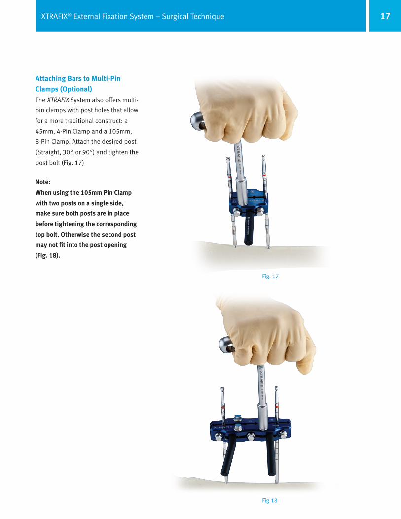
Attaching Bars to Multi-Pin Clamps (Optional)The XTRAFIX System also offers multi-
pin clamps with post holes that allow
for a more traditional construct: a
45mm, 4-Pin Clamp and a 105mm,
8-Pin Clamp. Attach the desired post
(Straight, 30°, or 90°) and tighten the
post bolt (Fig. 17)
Note:
When using the 105mm Pin Clamp
with two posts on a single side,
make sure both posts are in place
before tightening the corresponding
top bolt. Otherwise the second post
may not fit into the post opening
(Fig. 18).
Fig. 17
Fig.18
18 XTRAFIX® External Fixation System – Surgical Technique
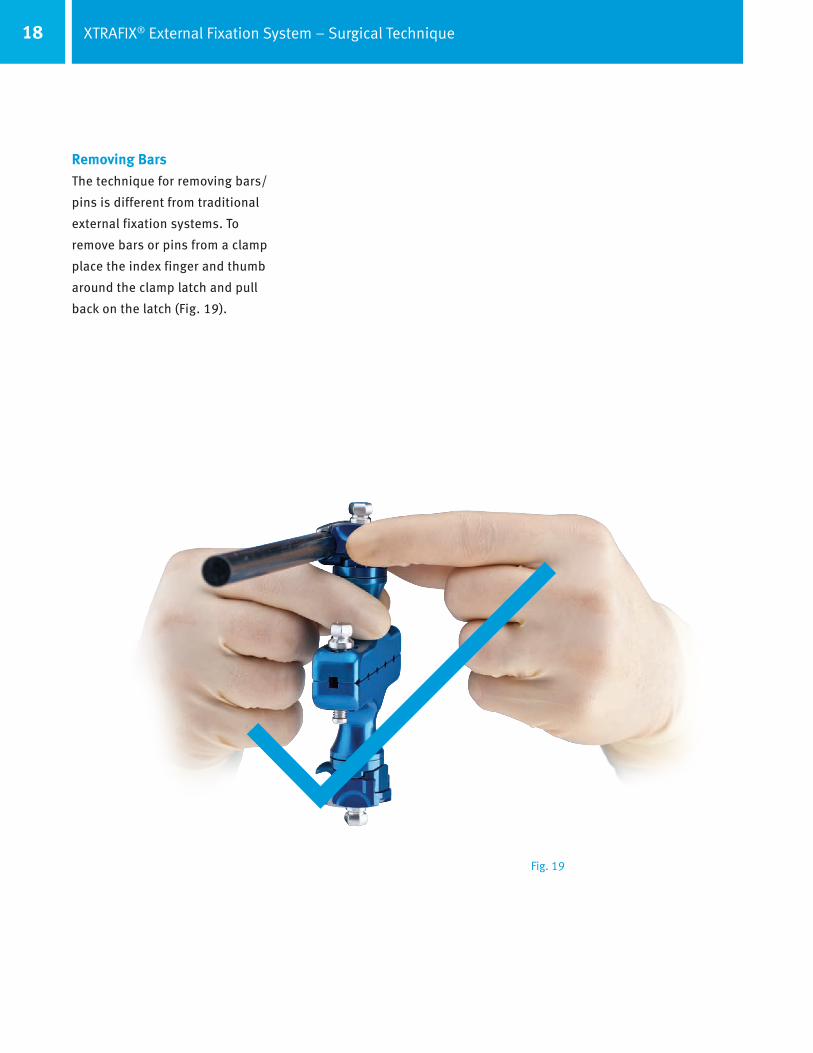
Removing BarsThe technique for removing bars/
pins is different from traditional
external fixation systems. To
remove bars or pins from a clamp
place the index finger and thumb
around the clamp latch and pull
back on the latch (Fig. 19).
Fig. 19
19XTRAFIX® External Fixation System – Surgical Technique
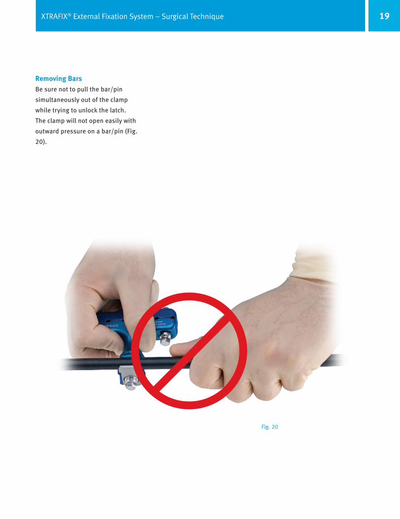
Removing BarsBe sure not to pull the bar/pin
simultaneously out of the clamp
while trying to unlock the latch.
The clamp will not open easily with
outward pressure on a bar/pin (Fig.
20).
Fig. 20

20 XTRAFIX® External Fixation System – Surgical Technique
1
Efficiency Multi-Pin Clamps
45mm, 2-Bar, Multi-Pin Efficiency ClampFive parts in one: Replaces two
Bar-to-Bar Clamps, two Posts, and
a 45mm Multi-Pin Clamp. Also, only
requires ONE nut to be tightened,
vs. six with the five individual
components (Fig. 21).
The 45mm, 2-bar clamp is locked
on the pins and both bars by
tightening only one nut. Use the
wrench of choice to tighten the nut
(Fig. 22).
Fig. 21
Fig. 22
1
3
45
2
21XTRAFIX® External Fixation System – Surgical Technique
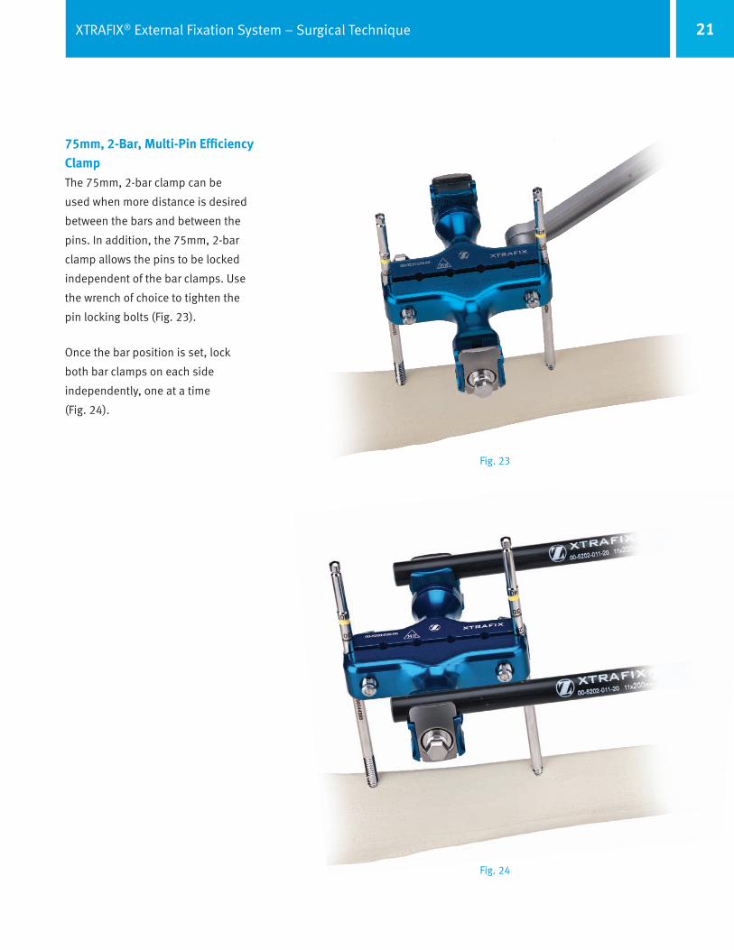
75mm, 2-Bar, Multi-Pin Efficiency ClampThe 75mm, 2-bar clamp can be
used when more distance is desired
between the bars and between the
pins. In addition, the 75mm, 2-bar
clamp allows the pins to be locked
independent of the bar clamps. Use
the wrench of choice to tighten the
pin locking bolts (Fig. 23).
Once the bar position is set, lock
both bar clamps on each side
independently, one at a time
(Fig. 24).
Fig. 23
Fig. 24

22 XTRAFIX® External Fixation System – Surgical Technique
45mm, 1-Bar Pin Clamp
When two transfixing pins are
preferred (e.g..) through the
calcaneous in a pilon fracture
procedure). the XTRAFIX System
offers surgeons a choice in Efficiency
Clamps. The 45mm, 1-Bar Pin Clamp
attaches to both pins and has a
pivoting, swivel bar attachment that
allows for easy connection to a tibial
clamp. Secure the 45mm, 1-Bar Pin
Clamp to the pins by tightening the
two pin locking bolts. Then adjust
the pivot and swivel as desired
and tighten the nut by the bar
attachment.
Note:
1. This clamp could also be used in
other situations: as a pelvic multi-
pin clamp, a tibial clamp with a post
and Bar-to-Bar clamp attached on
one side, etc.

23XTRAFIX® External Fixation System – Surgical Technique
Sample Constructs
Pin-to-Bar ConstructThe unmatched 80° of motion in
the XTRAFIX clamp allows pins to be
placed where the fracture – not the
fixator – dictates.

24 XTRAFIX® External Fixation System – Surgical Technique
Tibial Frame ConstructThe 45mm, 2-Bar Multi-Pin Clamps
can save time, effort and weight
on the patient when compared to
standard external fixation constructs.
Only two nuts need to be tightened
for this construct.
Knee-Spanning ConstructThe unmatched 80° of motion in
the XTRAFIX clamp allows pins to be
placed where the fracture – not the
fixator – dictates.

25XTRAFIX® External Fixation System – Surgical Technique
Ankle-Spanning ConstructSingle Transfixing Pin, Bar-to-
Pin Clamps
Ankle-Spanning ConstructSingle Transfixing Pin, Metatarsal
Pins, Bar-to-Pin Clamps

26 XTRAFIX® External Fixation System – Surgical Technique
Ankle-Spanning ConstructDouble Transfixing Pins, Single Bar
per Side
Ankle-Spanning ConstructDouble Transfixing Pins, Double Bars
per Side

27XTRAFIX® External Fixation System – Surgical Technique
Pelvic ConstructTwo 5x250mm Pins, Bar-to-Pin
Clamps, Curved Bar
Pelvic ConstructFour 5x250mm Pins, 1-Bar Pin
Clamps, Curved Bar
DisclaimerThis documentation is intended exclusively for physicians and is not intended for laypersons. Information
on the products and procedures contained in this document is of a general nature and does not represent
and does not constitute medical advice or recommendations. Because this information does not purport
to constitute any diagnostic or therapeutic statement with regard to any individual medical case, each
patient must be examined and advised individually, and this document does not replace the need for such
examination and/or advice in whole or in part.
Federal U.S. Law restricts this device to the sale, distribution, and use by or on the order of a physician. See
the package insert for complete product information including contraindications, warnings, precautions,
adverse effects and MR-Conditional information/testing parameters.
References
1 Design encircles the bar/pin to provide a positive and secure connection
Copy
righ
t ©20
12 Z
imm
er, I
nc. 9
7-52
10-0
00-0
0
Contact your Zimmer representative or visit us at www.zimmer.com