XSNet C6108SW - tkhs-install-files.s3.eu-central-1 ...
149
XSNet C6108SW Hardened Managed Gigabit Switch User Manual Quick Links: Quick Start Guide Table of Contents Web Interface Configuration CLI Configuration
Transcript of XSNet C6108SW - tkhs-install-files.s3.eu-central-1 ...

XSNet C6108SW Hardened Managed Gigabit Switch User Manual
Quick Links: Quick Start Guide Table of Contents Web Interface Configuration CLI Configuration

XSNet C6108SW
2
Quick Start Guide
This quick start guide describes the basic steps needed to install and start using the switch.
LED State Indication
Power 1
Power 2
Steady Power on
Off Power off
10/100/1000Base-TX
LINK/ACT
Steady Valid network connection established
Flashing Transmitting or receiving data ACT stands for ACTIVITY
100 Steady Connection at 100Mbps
1000Base SFP
LINK/ACT
Steady Valid network connection established
Flashing Transmitting or receiving data
ACT stands for ACTIVITY
1000 Steady Connection at 1000Mbps speed

XSNet C6108SW
3
Power Input Assignment
Power 2 + 12-48VDC
5-Pin
Terminal
Block
- Power Ground
Power 1 + 12-48VDC
- Power Ground
Earth Ground
Relay Output Rating 1A @ 250VAC
Relay Alarm Assignment
FAULT
Normal state is relay open, alarm state is closed. Alarm relay can be configured to power input or port failure. See: Diagnostics/Alarm Setting in web
interface.
Power Consumption: Max 17.3 Watts
The Fault LED indicator will light up to if either Power 1 or Power 2 ceases to function. However, the switch will continue to work normally even if the fault LED is lit, as long as the other power source is functioning.
Relay Output Alarm
The switch provides relay output contacts for signaling of a user-defined power or port failure. The relay output can be connected to an alarm signaling device. Current is 1A at 250VAC.
Console Configuration / Setting IP Address
Connect to the switch console: Connect the DB9 straight cable to the RS-232 serial port of the device and the RS-232 serial port of the terminal or computer running the terminal emulation application. Direct access to the administration console is achieved by

XSNet C6108SW
4
directly connecting a terminal or a PC equipped with a terminal-emulation program (such as HyperTerminal or Putty) to the switch console port.
Configuration settings of the terminal-emulation program: Baud rate: 115,200bps Data bits: 8 Parity: none Stop bit: 1 Flow control: none
Press the “Enter” key. The Command Line Interface (CLI) screen should appear.
Logon to Exec Mode (View Mode): At the “switch_a login:” prompt, enter “root” and press <Enter> to log on to Exec Mode (also called View Mode). The “switch_a>” prompt will be displayed.
Logon to Privileged Exec Mode (Enable Mode):
At the “switch_a>” prompt type in “enable” and press <Enter>. The “switch_a#” prompt will show on the screen.
Logon to Global Configuration Mode (Configure Terminal Mode): At the “switch_a#” prompt type in “configure terminal” and press <Enter>. The “switch_a(config)#” prompt will show on the screen.
Set new IP address and subnet mask for Switch: At the “switch_a(config)#” prompt enter “ip address A.B.C.D/M”, where “A.B.C.D” specifies the IP address and “M” specifies the subnet mask. “M”= 8: 255.0.0.0, 16:255.255.0.0, and 24: 255.255.255.0. Example: Enter IP address of 192.168.100.1/24 to set a new IP address of 192.168.100.1 with a subnet mask of 255.255.255.0. (See example image below)
Save changes with the “write memory” command.

XSNet C6108SW
5
Web Configuration
Log in to the switch:
Specify the default IP address (192.168.1.10) of the
switch in the web browser. A login window will be shown
(see below).
Enter the factory default login ID: root.
Enter the factory default password (no password).
Click on the “Login” button to log on to the switch. The
System Information screen will display (see figure below).

XSNet C6108SW
6

XSNet C6108SW
7
Table of Contents
Quick Start Guide 2 Console Configuration / Setting IP Address 3 Web Configuration 5
Table of Contents 7 Introduction 9
Product Highlights 9 Switch Password Reset 10 Installation 11
Selecting a Site for the Switch 11 Connecting to Power 11 Connecting to a Network 13
Web-Based Browser Management 14 Logging on to the switch 14 Switch Management Using Browser Interface 15 System 15 Diagnostics 21 Port 25 Switching 30 Trunking 38 STP / Ring 40 VLAN 51 QoS 54 Access Lists 63 SNMP 65 802.1x 70 LLDP 73 ROUTING 78 RIP 81 Other Protocols 85
Command Line Console Management 95 Administration Console 95 Navigating the CLI Hierarchy 96 Management Interface Configuration 98 System 99

XSNet C6108SW
8
Diagnostics 104 Port 106 Switching 107 Trunking 111 STP / Ring 112 VLAN 119 QoS 121 IP ACL 128 SNMP 130 LLDP 133 Routing 135 RIP 137 Other Protocols 139

XSNet C6108SW
9
Introduction
This manual describes how to install and use the Hardened Managed Ethernet Switch. This switch is a light Layer 3 full Gigabit hardened managed switch in din-rail form factor, featuring 8 ports of 10/100/1000BASE TX and 4 x 1000BASE SFP/SC/ST ports. To get the most out of this manual, you should have an understanding of Ethernet networking concepts.
Product Highlights
Manageable via SNMP, Web-based, Telnet, and RS-232 console port.
Supports 802.3/802.3u/802.3ab/802.3z/802.3x. Auto-negotiation: 10/100/1000Mbps, full/half-duplex. Auto MDI/MDIX
Equipped with 8x 10/100/1000BASE-TX slots Equipped with 4x 1000Base- SFP slots Supports 16K MAC addresses. Provides 12M bits
packet memory buffer Alarms for power and port link failure by relay output Power Supply: Redundant DC Terminal Block power
inputs Operating Temperature: -40° to 75°C (-40° to 167°F) Storage Temperature: -40° to 85°C (-40° to 185°F) Supports DIN-Rail and Panel Mounting installation

XSNet C6108SW
10
Switch Password Reset If the password to the switch is forgotten or lost, it can be reset through the reset button Press and hold the reset button, located next to the console port, for ten seconds. The switch will reboot and reset the switch password to the default: “root”. Other settings will not be affected.
Use a narrow object such as a pencil tip
to press and hold the reset button.

XSNet C6108SW
11
Installation
Selecting a Site for the Switch
As with any electric device, you should place the switch where it will not be subjected to extreme temperatures, humidity, or electromagnetic interference. Specifically, the site you select should meet the following requirements: The relative humidity should be less than 95 percent,
non-condensing.
Surrounding electrical devices should not exceed the electromagnetic field (RFC) standards.
Make sure that the switch receives adequate ventilation. Do not block the ventilation holes on each side of the switch.
Connecting to Power
Redundant DC Terminal Block Power Inputs
There are two pairs of power inputs for use with redundant power sources. Only one power input is needed to run the switch. Connect the DC power cord to the plug-able terminal block on the switch, and then plug it into a standard DC outlet.

XSNet C6108SW
12
Switch Top View
Power Input Assignment
Power2 + 12-48VDC
Terminal
Block
- Power Ground
Power1 + 12-48VDC
- Power Ground
Earth Ground
Relay Output Rating 1A @ 250VAC
Relay Alarm Assignment
FAULT
Normal state is relay open, alarm state is closed. Alarm relay can be configured to power input or port failure. See: Diagnostics/Alarm Setting in web interface.
Relay Alarm for Power or Port Failure
The switch provides relay output contacts for signaling of a user-defined power or port failure. The relay output can be connected to an alarm signaling device. Current is 1A at 250VAC. Special note: Do not connect a power source to relay output terminal. Doing so may result in shorting out the power supply.

XSNet C6108SW
13
Connecting to a Network
Cable Type & Length
Follow the cable specifications below when connecting the switch to your network. Use appropriate cables that meet your speed and cabling requirements.
Cable Specifications
Speed Connector Port Speed Half/Full Duplex
Cable Max.
Distance
10Base-T RJ-45 10/20 Mbps 2-pair UTP/STP Cat. 3, 4, 5
100 m
100Base-TX RJ-45 100/200 Mbps
2-pair UTP/STP Cat. 5
100 m
1000Base-T RJ-45 2000 Mbps 4-pair UTP/STP Cat. 5
100 m
SFP
100Base-FX Duplex LC 200 Mbps MMF (62.5μm)
2 km
100Base-FX Duplex LC 200 Mbps SMF (10μm) 20, 40, 75, 100 km
100Base-BX Duplex LC 200 Mbps MMF (62.5μm)
2, 5 km
100Base-BX Duplex LC 200 Mbps SMF (10μm) 20, 40 km
1000Base-SX Duplex LC 2000 Mbps MMF (62.5μm)
550 m 2 km
1000Base-LX Duplex LC 2000 Mbps SMF (9μm) 10, 40, 60 km
1000Base-BX Duplex LC 2000 Mbps SMF (9μm) 70 km

XSNet C6108SW
14
Web-Based Browser Management
The switch provides a web-based browser interface for configuring and managing the switch. This interface allows you to access the switch using a preferred web browser.
Logging on to the switch
SWITCH IP ADDRESS In your web browser, specify the IP address of the switch. Default IP address is 192.168.1.10. LOGIN Enter the factory default login ID: root. PASSWORD Enter the factory default password (no password). Or enter a user-defined password if you followed the instructions later and changed the factory default password.

XSNet C6108SW
15
Switch Management Using Browser Interface
The web browser interface provides groups of point-and-click buttons at the left field of the screen for configuring and managing the switch.
System
System Information The System information page that shows the following: System Name — The System name is typically used by network administrators. If SNMP is enabled on the switch, the system name can be found using MIB II (RFC1213) in the sysName property. Firmware Version — This displays the primary firmware version and date of last update System Time — System time can be changed using NTP MAC Address — The hardware (MAC) address of the Management interface Default Gateway — The IP address of your networks Gateway (Typically a Router on your network) DNS Server — The Dynamic Name Server (DNS) for your network

XSNet C6108SW
16
Alternate Firmware — This shows the firmware version mirrored on the switch. If the switch becomes unbootable from the primary firmware image, it will boot to this version on the next boot. VLAN ID — One or more listings depending on the number of VLANs defined on the switch. Lists VLAN ID, IP address, and subnet mask of the VLAN Interface(s)
System Name/Password By default there is no password assigned to the switch. To add or change a password: 1. System Name: Enter the new system name. 2. Update Setting: Click “Update Setting” button to save the
new system name. 3. Password: Enter new password, and re-enter in “Retype
Password” text box. 4. Update Setting: Click “Update Setting” button to update
your settings.

XSNet C6108SW
17
IP Address 1. Enter the desired IP address and subnet mask in the IP
Address/Subnet Mask fields associated with VLAN 1 2. You will need to enter the new IP address in the browser
and reconnect to the switch after IP or subnet mask are changed.
3. DHCP Client: Click “DHCP Client” drop-down menu to choose “Disable,” “VLAN1,” or other VLAN group from the “DHCP Client” drop-down list to disable or enable DHCP Client Setting for the switch. The management VLAN is VLAN 1 by default. The managed IP Address will be assigned by DHCP Server when VLAN 1 is chosen as DHCP Client. DHCP Server can assign the Switch another managed IP Address by choosing another VLAN besides VLAN 1 as DHCP Client when Switch has multiple VLANs. Then click “Submit.”
4. Default Gateway: Click “Default Gateway” drop-down menu to choose “Disable” or “Enable” from the “Default Gateway” drop-down list to disable or enable Default

XSNet C6108SW
18
Gateway Setting for the switch. Enter the address for the Default Gateway. Then click “Submit.”
5. DNS Server: Click “DNS Server” drop-down menu to choose “Disable” or “Enable” from the “DNS Server” drop-down list to disable or enable DNS Server Setting for the switch. Click the text box and type a new address to change the DNS Server. (Need to choose “Enable” from the “DNS Server” drop-down menu.)
6. Submit: Click “Submit” button when finished. Note: After making changes to settings in the IP address section, the configuration needs to be saved using the System/Save configuration page (See Save Configuration below).
Management Interface The Management Interface configuration page has three settings that allow the user to configure the methods available to manage the switch. HTTPS (Hypertext Transfer Protocol Secure) allows the user to determine what method, if any, is used to configure the switch. The default is unencrypted HTTP. To disable the Web interface: 1. Uncheck Http and Https. 2. Click on the Update setting button.

XSNet C6108SW
19
Warning! Once the Submit button is pressed, the Web Console will no longer function. As a safety precaution, the configuration is not saved by default. Rebooting the switch will restore the Web Console. To save the configuration, connect using the new IP address. Telnet is a network protocol that allows a remote computer to log into the switch to access its CLI (Command Line Interface). The CLI can be access using Telnet, SSH and the serial port on the switch. The secure method of accessing the CLI over a network is SSH. Secure Shell or SSH is a network protocol that allows data to be exchanged using a secure channel between two networked devices such as a computer and the switch. SSH is disabled by default on the Switch.
Save Configuration 1. To load a configuration from a TFTP server:
Click in “TFTP Server” text box and type the TFTP server IP address from where the file will be obtained. Click in “FILE” text box and type the name of the file that will be obtained. Click “Load” button to load the file from the TFTP server.
2. To back up a configuration to TFTP server:

XSNet C6108SW
20
Click in “TFTP Server” text box and type the TFTP server IP address to where the file will be backupped. Click in “FILE” text box and type the name of the file that will be backupped. Click “Backup” button to backup the file to the TFTP server.
3. To save current switch configuration: Click “Save Configuration” button to save your configuration settings.
4. Restore default configuration: Click “Restore Default” button to restore the default settings of the switch.
5. Auto save settings: Choose “Disable” or “Enable” from the “Auto save” drop-down list to disable or enable Auto save for the switch.
6. Auto save interval (5~65536 seconds): Click in “Auto save interval” text box and enter a number between 5 and 65536.
7. Submit: Click “Submit” button when you have finished Auto save configuration.
Firmware Upgrade To upgrade the firmware, a TFTP server is required. The firmware file for the switch is in a .TGZ or .IMG format. This is a compressed file; however, it should not be decompressed before updating the switch. To update the firmware 1. Copy the firmware file to the correct directory for your
TFTP server. The correct directory depends on your TFTP server settings
2. Enter the filename of the firmware in the Filename text box.

XSNet C6108SW
21
3. Enter the IP Address of your TFTP server in the TFTP Server IP text box, then click the Upgrade button.
4. During the firmware upgrade you will see the following messages. Do not reboot or unplug the switch until the final message is received.
a. Downloading now, please wait...
b. tftp <filename>.img from ip <ip address>
success!! Install now. This may take
several minutes, please wait...
c. Firmware upgrade success!
Reboot the switch after the firmware has been updated. Note: If a Firewall is running on the PC that is running the TFTP server it may need to be temporarily disabled.
Reboot Reboot: Click “Reboot” button to restart the switch. Logout Logout: Click “Logout” button to logout of the switch.
Diagnostics
Utilization The Utilization page is a read-only page that shows the switch’s CPU and memory utilization.
XSNet C6108SW
22
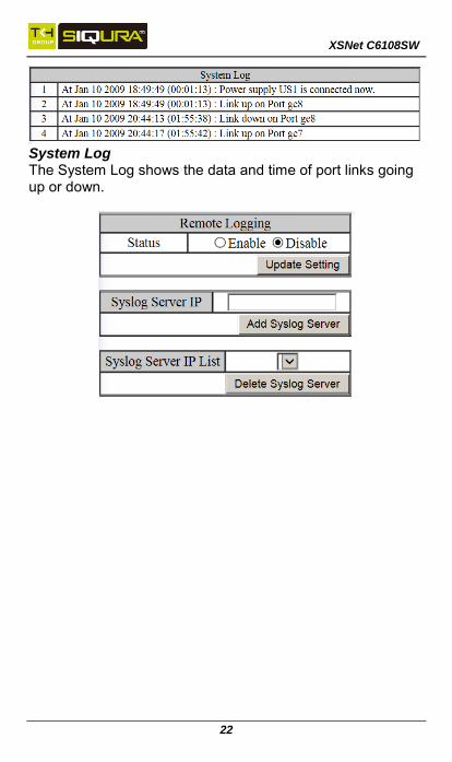
System Log The System Log shows the data and time of port links going up or down.

XSNet C6108SW
23
Remote Logging Remote Logging to a Syslog server allows administrators to log important system and debugging information. The Remote Logging configuration page allows reporting to a Syslog server to be enabled or disabled as well as management of a list of Syslog servers to report to.
ARP Table The ARP Table page shows ARP (Address Resolution Protocol) entries that are stored in the Switches ARP Table. This is useful for troubleshooting purposes. The information shown is:
•IP Address of the listed device
•Hardware Type – For Ethernet devices this will always be 1.
•Flags
2 = Device responded to ARP Request 0 = No response to ARP Request
•Hardware Type – MAC Address of the listed device
•VLAN – The VLAN that the listed device is on
Route Table Route Table lists the routes to network destinations. And metrics (distances) are associated with those routes. The Route Table contains information about the topology of the network around it.

XSNet C6108SW
24
Alarm Setting The Alarm Setting page allows users to define Ethernet port Link-down and Power failure alarms for triggering an alarm using the relay on the switch. To configure an Ethernet port or power input: 1. Select an Ethernet port or Power input from the dropdown
box. 2. Select YES or NO from the dropdown box next to Trigger
Enabled. 3. Click Update Setting to save any changes made. NOTE: The initial normal state of the relay is open, and if switch loses *all* power, then this state will come into effect. This is important to remember when using the relay to indicate a power failure. The relay will close in an alarm state when there is redundant power input and an alarmed input fails.

XSNet C6108SW
25
Port
Configuration To provide a description to a port: 1. Click in the Description text box for the appropriate port. 2. Type in the description of the port. 3. Click on the Submit button. To enable or disable a port: 1. Click on the drop-down box under Admin Setting and
select either Link Up or Link Down. 2. Click on the Submit button. To set the Port Speed and/or Port Duplex Settings: 1. Click on the drop-down box under Speed and select the
desired port speed / duplex settings for that port. Please note, not all port types will have the same options. For example, 100Mb fiber ports will typically be limited to a single option of 100M/FD (100Mbps and Full Duplex) while running 1Gb UTP ports will have six options for speed/duplex.
2. Click on the Submit button. To enable or disable a port's Flow Control: 1. Click on the drop-down box under Flow Control and
select either Enable or Disable. 2. Click on the Submit button.

XSNet C6108SW
26
Port Status View the Link Status, Port Description, Speed, Duplex, and Flow control status for all ports.

XSNet C6108SW
27
Rate Control The Rate Control page allows the user to set the maximum throughput on a port or ports on both packets entering the port (from the connected device) or packets leaving the port. The Ingress text box controls the rate of data traveling into the port while the Egress text box controls the rate of data leaving the port. Note: Entries will be rounded down to the nearest acceptable rate value. If the value entered is below the lowest acceptable value then the lowest acceptable value will be used. To provide either an ingress or egress rate control for a port: 1. Click in the Ingress or Egress Text Box for the appropriate
port. 2. Type in the ingress/egress rate for the port according to
the values listed above. 3. Click on the Update Setting button.

XSNet C6108SW
28
RMON Statistics Click ports to view corresponding RMON Statistics.

XSNet C6108SW
29
Per Port VLAN Activities Click ports to view corresponding VLAN activities.

XSNet C6108SW
30
Switching
Bridging Ageing Time The Ageing Time value is a global value and represents the time that a networked device's MAC address will live in the switch's memory before being removed. The default value is 300 seconds (5 minutes) To update the Ageing Time value: 1. Click in the Error Disable Recovery text box at the top of
the Port Security Dynamic-MAC page. 2. Type in the desired value. Values can be from 0 to 65535
seconds. A value of 0 indicates that the port is not to return to normal operating condition until an administrator resets the port or the switch is restarted.
3. Click on the Update Setting button. Threshold Level The Threshold Level setting is a per port value. A traffic storm occurs when packets flood the LAN, creating excessive traffic and degrading network performance. The traffic storm control

XSNet C6108SW
31
feature prevents LAN ports from being disrupted by a broadcast or multicast traffic storm on physical interfaces. A Threshold is set to determine when the switch will react to Broadcasts and/or Multicasts. To set the Threshold level per port: 1. Type in the desired value. Values can be from 0.1 to 100.
This value is a percentage of allowable broadcast traffic for this port. Once this percentage of traffic is exceeded, all broadcast traffic beyond this percentage is dropped.
2. Click on the Update Setting button. Storm Control Type The Storm Control Enabled Type setting is a per port value. The Storm Control Enabled Type allows users to determine the type of storm control to be used by the switch. To set the Storm Control Enabled Type: 1. Select the check box next to Broadcast and/or
DFL-Multicast for the port that needs to be changed 2. Click on the Update Setting button.

XSNet C6108SW
32
Loopback Detect (Global) To globally enable the Loopback Detect feature of the switch: 1. Click on the Loopback Detect drop-down box. 2. Select Enable from the drop down list. 3. Click on the Update Setting button.
Loopback Detect Action To change the action that the switch takes when a loopback condition is detected: 1. Choose an action from the Loopback Detect Action
dropdown list. The available options are None and Error Disable.

XSNet C6108SW
33
2. Click on the Update Setting button.
Loopback Detect Recovery Time To change the length of time that the Loopback Detect
Action will stay in effect: 1. Enter a value in the text box next to Error Disable
Recovery. Valid values range from 0 to 65535 seconds.
2. Click on the Update Setting button.
Polling Interval To change the polling interval of the Loopback Detect
function: 1. Enter a value in the text box next to Interval. Valid
values range from 1 to 65535 seconds. 2. Click on the Update Setting button.
Loopback Detection (Per Port) To enable Loopback Detection for a particular port or ports on the switch: 1. Select the value Enable from the Mode drop down list
for a port on the Loopback Detect page. 2. Click on the Update Setting button.

XSNet C6108SW
34
Storm Detect The Storm Detect feature allows the switch to be configured
to disable a port that is receiving a large number of Broadcast
and/or Multicast packets. The switch can monitor for
packets and take action based on percentage of bandwidth
utilization or number of packets per second.
Enable/Disable Storm Detection 1. Enable or Disable Storm Detection by Clicking on the
drop down box in the Storm-Detect Configuration box. 2. Set the Storm Detect interval to a number between 2
and 65535 seconds. The default value is 10 seconds. 3. Set the Storm-Detect errdisable-recovery time to value
between 0 and 65535 seconds. The Default is 0 (disabled). This value determines if the switch should

XSNet C6108SW
35
re-enable the port after the specified value or leave the port disabled.
4. Set the By Utilization(%) for each port in the Storm-Detect Per Port Configuration box. The default is 0 (not limited). Setting this to a value between 1 and 100 will cause the port to be disabled when the defined percentage of bandwidth is reached.
5. Set the type of packet to be monitored in the Drop-down box under By Broadcast / Multicast+Broadcast Packets Per Second. Set the value to BC to monitor Broadcast packets and BC-MC to monitor both Broadcast and Multicast packets.
Static MAC Entry Static-MAC-Entry Forward: 1. Add MAC address: Click in “Add MAC address” text box
and type a locked forwarding MAC address for the port.

XSNet C6108SW
36
2. VLAN ID: Click “VLAN ID” drop-down menu and choose a VLAN ID from the “VLAN ID” drop-down list.
3. Delete MAC address: Click “Delete MAC address” drop-down menu and choose a locked forwarding MAC address from the “Delete MAC address” drop-down list to be deleted from the port.
4. Submit: Click “Submit” button when you have finished Static-MAC-Entry Forward settings.
Static-MAC-Entry Discard: 1. Add MAC address: Click in “Add MAC address” text box
and type a MAC address to be discarded for the VLAN. 2. VLAN ID: VLAN ID: Click “VLAN ID” drop-down menu and
choose a VLAN ID from the “VLAN ID” drop-down list. 3. Delete MAC address: Click “Delete MAC address”
drop-down menu and choose a MAC address from the “Delete MAC address” drop-down list to be discarded from the VLAN.
4. Submit: Click “Submit” button when you have finished Static-MAC-Entry Discard settings.
XSNet C6108SW
37
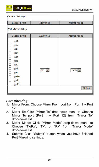
Port Mirroring 1. Mirror From: Choose Mirror From port from Port 1 ~ Port
12. 2. Mirror To: Click “Mirror To” drop-down menu to Choose
Mirror To port (Port 1 ~ Port 12) from “Mirror To” drop-down list.
3. Mirror Mode: Click “Mirror Mode” drop-down menu to Choose “Tx/Rx”, “Tx”, or “Rx” from “Mirror Mode” drop-down list.
4. Submit: Click “Submit” button when you have finished Port Mirroring settings.

XSNet C6108SW
38
Trunking
Port Trunking To create a trunk consisting of 1000Mbps ports: 1. Select Static, LACP, or Disable for each trunk that is
being configured. 2. Click on the corresponding checkbox for each desired
port to be included in the Trunk Group. A maximum of eight ports can be assigned to each trunk group.
3. Click on the Submit button.

XSNet C6108SW
39
LACP Trunking Trunk Configuration: To create a LACP trunk: 1. In the Trunk Configuration section, select a port in the
LACP trunk. 2. Select LACP from the Trunk Type dropdown box for this
port. 3. Enter an admin key for this port in the Admin Key textbox.
100Mbps ports admin keys must be 1 and 1Gbps ports must be 3.
4. Select the LACP Mode to either Active or Passive. 5. Enter a value in the Port Priority textbox. 6. Select a Timeout value of Short or Long. 7. Click on the Submit button. 8. Repeat steps 1-7 for each additional port that is to be
used in the trunk. To set the LACP System Priority 1. Enter a value between 1 and 65535. The default value is
32768. 2. Click on the Submit button.

XSNet C6108SW
40
STP / Ring
Global Configuration 1. Spanning Tree Protocol: Click “Spanning Tree Protocol”
drop-down menu to choose “Enable” or “Disable” from “Spanning Tree Protocol” drop-down list to enable or disable Spanning Tree Protocol.
2. Bridge Priority (0..61440): Click in “Bridge Priority” text box and type a decimal number between 0 and 61440.
3. Hello Time (sec) (1..9): Click in “Hello Time” text box and type a decimal number between 1 and 9.
4. Max Age (sec) (6..28): Click in “Max Age” text box and type a decimal number between 6 and 28.
5. Forward Delay (sec) (4..30): Click in “Forward Delay” text box and type a decimal number between 4 and 30.
6. STP Version: Click “STP Version” drop-down menu to choose “MSTP”, “RSTP”, or “STP compatible” from “STP

XSNet C6108SW
41
Version” drop-down list. 7. Update Setting: Click “Update Setting” button when you
have finished Global Configuration.
RSTP Port Setting 1. Port: Click “Port” drop-down menu to Choose Port 1 ~
Port 12 from “Port” drop-down list. 2. Priority (Granularity 16): Click in “Priority” text box and
enter a value between 0 and 240 to set the priority for the port. A higher priority will designate the port to forward packets first. A lower number denotes a higher priority. This entry must be divisible by 16. The default priority setting is 128.
3. Admin. Path Cost: Click in “Admin. Path Cost” text box and enter a value between 0 and 2000000 to set the Admin. Path Cost for the port. 0 (auto) - Setting 0 for the Admin. Path Cost will automatically set the speed for forwarding packets to the port for optimal efficiency. Default port cost: 100Mbps port = 200000. Gigabit port = 20000.
4. Point to Point Link: Click “Point to Point Link” drop-down menu to Choose “Enable” or “Disable” from “Point to Point Link” drop-down list to enable or disable Point to

XSNet C6108SW
42
Point Link for the port. 5. Edge Port: Click “Edge Port” drop-down menu to Choose
“Enable”, “Disable”, or “Auto” from “Edge Port” drop-down list to set Enable, Disable, or Auto Edge Port for the port.
6. Update Setting: Click “Update Setting” button when you have finished RSTP Port Setting.
MSTP Properties 1. Region Name: Click in “Region Name” text box to create
an MST region and specify a name to it. MST bridges of a region form different spanning trees for different VLANs. By default, each MST bridge starts with the region name as its bridge address. This means each MST bridge is a region by itself, unless specifically added to one.
2. Revision Level: Click in “Revision Level” text box to specify the number for configuration information. The default value of revision number is 0.
3. Max Hops: Click in “Max Hops” text box to specify the maximum allowed hops for BPDU in an MST region. This parameter is used by all the instances of the MST. Specifying the max hops for a BPDU prevents the messages from looping indefinetely in the network. When a bridge receives a MST BPDU that has exceeded the allowed max-hops, it discards the BPDU.
4. Update Setting: Click “Update Setting” button when you have finished MSTP Properties setting.

XSNet C6108SW
43
MSTP Instance Setting VLAN Instance Configuration 1. VLAN Instance Configuration: Click “VLAN Instance
Configuration” button. The “VLAN Instance Configuration” window appears.
2. VLAN ID: Click “VLAN ID” drop-down menu to choose VLAN from “VLAN ID” drop-down list to simultaneously add multiple VLANs for the corresponding instance of a bridge.
3. Instance ID (1..15): Click in “Instance ID” text box to specify the instance ID.
4. Update Setting: Click “Update Setting” button when you have finished VLAN Instance Configuration.
Included VLANs 1. Instance ID: Click “Instance ID” drop-down menu to
choose instance ID from “Instance ID” drop-down list. 2. Included VLAN: Click “Included VLAN” drop-down menu
to choose VLAN from “Included VLAN” drop-down list.

XSNet C6108SW
44
Instance Setting 1. Bridge Priority (0..61440): Click in “Bridge Priority” text
box to set the bridge priority for an MST instance to the value specified. The lower the priority of the bridge, the better the chances are the bridge becoming a root bridge or a designated bridge for the LAN.
2. Update Setting: Click “Update Setting” button when you have finished VLAN Instance Configuration.

XSNet C6108SW
45
MSTP Port Setting Port Instance Configuration 1. Instance ID: Click “Instance ID” drop-down menu to
choose instance ID from “Instance ID” drop-down list. 2. Click Port 1 ~ Port 12 to assign ports to the corresponding
instance ID. 3. Update Setting: Click “Update Setting” button when you
have finished Port Instance Configuration. Instance ID 1. Instance ID: Click “Instance ID” drop-down menu to
choose instance ID from “Instance ID” drop-down list. MSTP Port Configuration 1. Port: Click “Port” drop-down menu to choose port from
“Port” drop-down list. 2. Priority(Granularity 16): Click in “Priority” text box to set
the port priority for a bridge group. The Multiple Spanning Tree Protocol uses port priority as a tiebreaker to determine which port should forward frames for a particular instance on a LAN, or which port should be the root port for an instance. A lower value implies a better priority. In the case of the same priority, the interface

XSNet C6108SW
46
index will serve as the tiebreaker, with the lower-numbered interface being preferred over others. The permitted range is 0-240. The priority values can only be set in increments of 16.
3. Admin. Path Cost: Click in “Admin. Path Cost” text box to set the cost of a path associated with an interface.
4. Update Setting: Click “Update Setting” button when you have finished MSTP Port Setting.
IQ Ring Setting Ring state 1. Click “Ring state” drop-down menu from “Ring state”
drop-down list to choose “Enable” or “Disable” to enable or disable Ring state.
2. Update Setting: Click “Update Setting” button when you have finished Ring state setting.
Set ring port 1. Ring port 1: Click “Ring port 1” drop-down menu to
choose Ring port 1 from “Ring port 1” drop-down list.

XSNet C6108SW
47
2. Ring port 2: Click “Ring port 2” drop-down menu to choose Ring port 2 from “Ring port 2” drop-down list.
3. Update Setting: Click “Update Setting” button when you have finished Set ring port.
Ring-coupling state 1. Click “Ring-coupling state” drop-down menu from
“Ring-coupling state” drop-down list to choose “Enable” or “Disable” to enable or disable Ring-coupling state.
2. Update Setting: Click “Update Setting” button when you have finished Ring-coupling state setting.
Set ring-coupling port 1. Ring-coupling port 1: Click “Ring-coupling port 1”
drop-down menu to choose Ring-coupling port 1 from “Ring-coupling port 1” drop-down list.
2. Ring-coupling port 2: Click “Ring-coupling port 2” drop-down menu to choose Ring-coupling port 2 from “Ring-coupling port 2” drop-down list.
3. Update Setting: Click “Update Setting” button when you have finished Set ring-coupling port.

XSNet C6108SW
48
IQ Chain Setting Chain Protocol 1. Click “Enable” to enable Chain Protocol for Port 1 ~ Port
12. The Chain Protocol supports up to total 8 ports. 2. Submit: Click “Submit” button when you have finished
Chain Protocol setting. Global Setting 1. Priority (1-255, default:128): Set the Switch priority for
running chain protocol. Switch with lower priority will run as Master (forwarding) port.
2. Timeout count (3-255, default:5): Set the Switch timeout count for running chain protocol. Chain recovery time = (Chain Timeout Count – 1) x 200ms. Default Chain recovery time = (5 – 1) x 200ms = 800ms.

XSNet C6108SW
49
3. Submit: Click “Submit” button when you have finished Chain Protocol setting.
Chain Pass-Through Setting To configure the IQ Chain Pass-Through ports:
1. From the drop-down list below the Chain Pass-Through Port 1 heading, choose one of the daisy chained ports on the switch to be the Chain Pass-Through Port #1 for the switch.
2. Next, from the drop-down list below the Chain Pass-Through Port 2 heading choose the remaining daisy chained port on the switch to be the Chain Pass-Through Port #2 for the switch.
3. To change the port number for either of the Chain pass-through ports on the switch, you must first click on the Disable button to clear the settings for both Chain Pass-Through ports. Repeat the previous steps to set the new port numbers to be Chain Pass-Through.
4. Click on the Submit button to load the changes into the running configuration.

XSNet C6108SW
50
STP/Ring Page - Advanced Setting The Advanced Setting Page contains several settings to determine how the switch will handle BPDU packets.
Bridge bpdu-guard configuration - When the BPDU Guard feature is set for a bridge, all portfast-enabled ports of the bridge that have bpdu-guard set to default
XSNet C6108SW
51
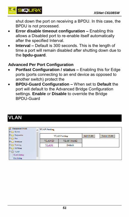
shut down the port on receiving a BPDU. In this case, the BPDU is not processed.
Error disable timeout configuration – Enabling this allows a Disabled port to re-enable itself automatically after the specified Interval.
Interval – Default is 300 seconds. This is the length of time a port will remain disabled after shutting down due to the bpdu-guard.
Advanced Per Port Configuration
Portfast Configuration / status – Enabling this for Edge ports (ports connecting to an end device as opposed to another switch) protect the
BPDU-Guard Configuration – When set to Default the port will default to the Advanced Bridge Configuration settings. Enable or Disable to override the Bridge BPDU-Guard
VLAN
XSNet C6108SW
52
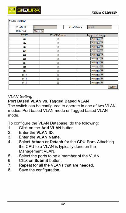
VLAN Setting Port Based VLAN vs. Tagged Based VLAN The switch can be configured to operate in one of two VLAN modes: Port based VLAN mode or Tagged based VLAN mode.
To configure the VLAN Database, do the following: 1. Click on the Add VLAN button. 2. Enter the VLAN ID. 3. Enter the VLAN Name. 4. Select Attach or Detach for the CPU Port. Attaching
the CPU to a VLAN is typically done on the Management VLAN.
5. Select the ports to be a member of the VLAN. 6. Click on Submit button. 7. Repeat for all the VLANs that are needed. 8. Save the configuration.

XSNet C6108SW
53
Port Setting Configuring the Port Type and the PVID setting To configure the proper port type and the PVID setting for each switch port: 1. Choose the port type for each port in the drop-down list. 2. Enter the PVID VLAN for each port. 3. Enter the Priority Level (optional). 4. Click on the Update Setting button. 5. Save the configuration.
Warning: Modifying the Port Type using the Web GUI will cause that switch port to lose all its current VLAN membership and become a member port for the PVID VLAN only. You will lose your current connection to the switch, should you choose to modify the PVID of the port that connects your Computer to the switch.

XSNet C6108SW
54
QoS
Global Configuration 1. QoS: Click “QoS” drop-down menu from “QoS”
drop-down list to choose “Enable” or “Disable” to enable or disable QoS.
2. Trust: Enable or disable the switch port to trust the CoS (Class of Service) labels of all traffic received on that port. Enable or disable a routed port to trust the DSCP (Differentiated Service Code Point) labels of all traffic received on that port.
3. Policy: Choose “Strict Priority(Queue3) + WRR(Queue0-2)” or “WRR(Queue0-3)”. A strict priority queue is always emptied first. The queues that are used in the WRR (Weighted Round Robin) are emptied in a round−robin fashion, and you can configure the weight for each queue.
4. Weighted Round Robin: Click in the “Weight(1~55)” textbox and specify a new number from 1 ~ 55 for Queue 0 ~ 3.
5. Submit: Click “Submit” button to save the configuration.
XSNet C6108SW
55
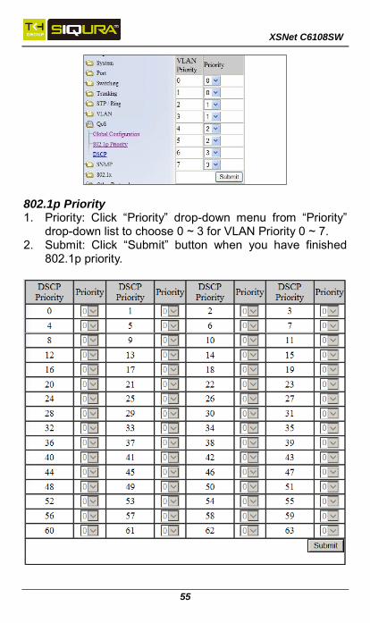
802.1p Priority 1. Priority: Click “Priority” drop-down menu from “Priority”
drop-down list to choose 0 ~ 3 for VLAN Priority 0 ~ 7. 2. Submit: Click “Submit” button when you have finished
802.1p priority.

XSNet C6108SW
56
DSCP 1. Priority: Click “Priority” drop-down menu from “Priority”
drop-down list to choose 0 ~ 3 for DSCP Priority 0 ~ 63. 2. Submit: Click “Submit” button.
Configuring ACL In order to enable the ACL feature on the switch, the QoS feature must be enabled on the switch as well. In order to apply the ACL packet filtering features on a port, you must: 1. Create and configure an ACL Access List first. 2. Next, you will need to create and configure an ACL Class
Map, 3. Associate the previously created ACL Access Lists to this
ACL Class Map. 4. Next, create and configure an ACL Policy Map 5. Associate all the appropriate and necessary ACL Classes
into this ACL Policy Map. 6. Then apply this ACL Policy Map (and all the Access Lists
that it contains) to a specific port. ACL Policy Map To create a new ACL Policy Map, follow the instructions below. 1. Make sure that the Create option is selected from the
drop-down list next to Policy Map.

XSNet C6108SW
57
2. Next, make sure that the Create option is selected from the drop-down list under Class Name.
Next, you will be creating a new ACL Access List which is necessary to create an ACL Class Map. From the information listed below you will find the configuration steps necessary for all of the four available ACL Access Lists. You can choose one Access List from the below list and follow the steps there to complete the configuration for that Access List. To configure an IP Access List: 1. Select the IP Access List option from the drop-down list
below Access List Type. 2. If you have already created an IP Access List previously
and would like to apply it to the new ACL Class, then select the Access List number from the drop-down list next to Access List.
3. If you want to create a new IP Access List, make sure that the Create option is selected from the drop-down list next to Access List.
4. To give the new IP access list an ID, enter a number in the range from 1 – 99, or from 1300 – 1999, into the entry field next to the “Create” option drop-down list.
5. You can enter a source IP address to allow an IP packet with that source IP to gain entry into the switch. To do this, choose the permit option from the drop-down list under the Action column.
6. Next, enter the source IP address into the entry field from the IP address column.
7. Next, enter the Comparison Mask for the source IP address in reverse logic, into the entry field from the Mask column. In reverse logic, 255.255.255.0 would be 0.0.0.255.
8. Next, click on the Add button.
9. You can enter a source IP address in order to deny an IP packet with that source IP to gain entry into the switch. To do so, you must choose the deny option from the drop-down list under the Action column. Next, enter the IP address and mask as described in step 6 and 7. You can also use the any wild card in lieu of entering a source

XSNet C6108SW
58
IP address in the entry field from the IP address column. You will need to do this if you wish to deny any additional IP packet from entry to the switch that did not match any of the previous rules from all the previous access control lists, otherwise these additional IP packets will also be allowed entry into the switch.
IP Access List (Extended) 1. Select the IP Access List (Extended) option from the
drop-down list below Access List Type. 2. To apply an existing Extended IP Access to the new ACL
Class, then select the Access List number for the previously configured Extended IP Access List from the drop-down list next to Access List.
3. if you want to create a new Extended IP Access List, verify that the Create option is selected from the drop-down list next to Access List.
4. To give this particular Extended IP access list an ID, enter a number in the range from 100 – 199, or from 2000 – 2699, into the entry field next to the Create option drop-down list.
5. You can enter a source and a destination IP address to allow an IP packet with these pair of IP addresses to gain entry into the switch. To do this, choose the permit option from the drop-down list under the Action column.
6. Next, enter the source IP address of the IP packet into the entry field under the Source Address column.
7. Next, enter the comparison Mask for the source IP address in reverse logic (a binary “0” in the mask means “this bit position needs to checked”, whereas a binary “1” in the mask means “this bit position does not need to be checked”) into the entry field from the Source Wildcard Bits column. In reverse logic, 255.255.255.0 is listed as 0.0.0.255.
8. Next, enter the destination IP address of the IP packet into the entry field under the Destination Address column.

XSNet C6108SW
59
9. Next, enter the comparison Mask for the destination IP address in reverse logic into the entry field from the Destination Wildcard Bits column.
10. Next, click on the Add button. 11. You can also filter the IP packet using the packet’s source
and destination Transport Layer protocol port numbers in addition to the source and destination IP addresses. enter the source Transport Layer protocol port number into the entry field under the port (1-65535) column following the source IP address comparison mask column. Next, enter the destination Transport Layer protocol port number into the entry field under the port (1-65535) column following the destination IP address comparison mask column.
12. To enter an extended IP access list entry in order to deny the entry of an IP packet into the switch, you must choose the deny option from the drop-down list under the Action column. Next, enter the IP addresses and Transport Layer protocol port numbers using the same steps as in the previous two bullets.
13. You can also use the any wild card in lieu of entering an IP address in the entry field from both the Source Address and Destination Address column. You will need to do this if you wish to deny any additional IP packet from entry to the switch that did not match any of the previous rules from all the previous access control lists, otherwise these additional IP packets will also be allowed entry into the switch.
Mac Access List 1. To configure a MAC access list, select the MAC Access
List option from the drop-down list below Access List Type.
2. If a MAC Access List was previously created and you would like to apply it to the new ACL Class, then select the Access List number for the previously configured MAC Access List from the drop-down list next to Access List. If you want to create a new MAC Access List, insure that the Create option is selected from the drop-down list next to Access List.
XSNet C6108SW
60
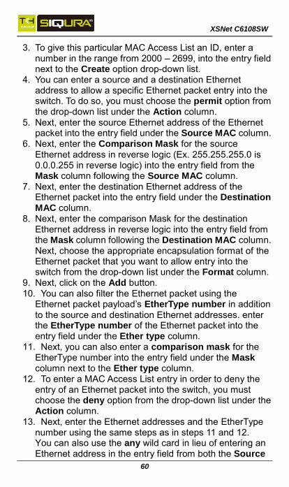
3. To give this particular MAC Access List an ID, enter a number in the range from 2000 – 2699, into the entry field next to the Create option drop-down list.
4. You can enter a source and a destination Ethernet address to allow a specific Ethernet packet entry into the switch. To do so, you must choose the permit option from the drop-down list under the Action column.
5. Next, enter the source Ethernet address of the Ethernet packet into the entry field under the Source MAC column.
6. Next, enter the Comparison Mask for the source Ethernet address in reverse logic (Ex. 255.255.255.0 is 0.0.0.255 in reverse logic) into the entry field from the Mask column following the Source MAC column.
7. Next, enter the destination Ethernet address of the Ethernet packet into the entry field under the Destination MAC column.
8. Next, enter the comparison Mask for the destination Ethernet address in reverse logic into the entry field from the Mask column following the Destination MAC column. Next, choose the appropriate encapsulation format of the Ethernet packet that you want to allow entry into the switch from the drop-down list under the Format column.
9. Next, click on the Add button. 10. You can also filter the Ethernet packet using the
Ethernet packet payload’s EtherType number in addition to the source and destination Ethernet addresses. enter the EtherType number of the Ethernet packet into the entry field under the Ether type column.
11. Next, you can also enter a comparison mask for the EtherType number into the entry field under the Mask column next to the Ether type column.
12. To enter a MAC Access List entry in order to deny the entry of an Ethernet packet into the switch, you must choose the deny option from the drop-down list under the Action column.
13. Next, enter the Ethernet addresses and the EtherType number using the same steps as in steps 11 and 12. You can also use the any wild card in lieu of entering an Ethernet address in the entry field from both the Source

XSNet C6108SW
61
MAC and Destination MAC column. You will need to do this if at any time this Access List should become the very last Access List rule in a ACL Policy Map to serve as the catch all deny rule in order to deny any and all types of packets from entry into the switch that did not match any of the previous rules from all the previous access control lists.
Layer 4 1. To use the Layer 4 access list feature and apply it to the
new ACL Class, select the Layer 4 option from the drop-down list below Access List Type.
2. You can enter a source or destination Transport Layer protocol port number to allow any IP packet with this port number to gain entry into the switch. To do this, choose the appropriate port number type (Source port or Destination port) from the drop-down list next to Option.
3. Next, enter the correct port number into the entry field next to “TCP/UDP Port No.(1-65535)”.
4. After you have finished configuring one ACL Access List from the previous step, you must now create a name for the new ACL Class Map that will be associated with this Access List. To do this, enter a name for the new ACL Class Map into the text box under Class Name.
Note: Since this particular Access List type does not contain any deny rules, this Access List will have to be used in conjunction with another type of Access List, if you wish to filter any packet from entry to the switch that did not match the classification rules from this Access Lists. Otherwise all packets that did not match the classification rules of this Access List will also be allowed entry into the switch.
Bandwidth Limiting 1. The amount of bandwidth that is being allocated for the
traffic that is being allowed under this new ACL Class can also be limited. To do this, enter the bandwidth amount that you want to allocate for the traffic in the entry fieldes in the Attach Class Map to Policy Map section.

XSNet C6108SW
62
Update the following fields:
Committed Information Rate (1-1000000 kbps)
Peak Information Rate(1-1000000kbps)
Committed Burst (1-20000 bytes)
Peak Burst (1-20000bytes) Note: The Peak rates must be higher than the Committed Rate. Current firmware discards any packets that exceed the Committed Rate 2. Next, enter a name in the entry field next to “Policy Map
Name” for the new ACL “Policy Map” that you are currently creating, and click on the submit button.
Applying a Policy Map to a Port To apply an ACL Policy Map to a port: 1. Select the correct ACL Policy Map from the drop-down list next to Policy Map.
2. Next, check the boxes below Attach Class Map to Policy Map next to all the ports that you would like to apply this Policy Map to.
3. Click on the Attach button.

XSNet C6108SW
63
Access Lists
IP-based Access Control Lists give the network administrator control over network traffic, and make it easier to implement security policies. Note that under the current firmware version, only inbound Access Control Lists are supported. Note that standard access lists can filter a packet based on the source IP address only. Extended access lists can filter on both the source and destination IP addresses in the packet. Creating an Access List To create an Access List: 1. Enter the number of the Access List (1 – 199 or 1300 –
2699) 2. Select the type of action: either Permit or Deny. 3. Choose Standard or Extended access list

XSNet C6108SW
64
4. Enter the source IP address and the source wildcard bits. 5. Enter the destination IP address and destination wildcard
bits. 6. Define the Source Ports by entering a number and
selecting an operator: eq (equal to), gt (greater than), lt (less than), or neq (not equal to). You can also enter a range of source ports into the field below and clicking the “range” radio button.
7. Define the destination ports in the same way as described for the source ports above.
8. Select the IP protocol 9. Click Add to create the new list.
Port ACL Settings To attach an existing Access List to a port, select the desired interface from the drop down menu, and then the Access List you wish to attach. Then click Update Setting. Remember to save the configuration before exiting the web interface.

XSNet C6108SW
65
SNMP
SNMP General Settings To configure the general settings for the SNMP feature: 1. The SNMP server on the switch can be enabled or
disabled by selecting the appropriate choice from the dropdown list next to SNMP Status.
2. Enter a short description (up to 256 characters) into the entry field next to Description, for the purpose of switch identification.
XSNet C6108SW
66
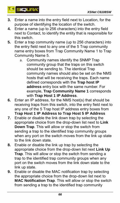
3. Enter a name into the entry field next to Location, for the purpose of identifying the location of the switch.
4. Enter a name (up to 256 characters) into the entry field next to Contact, to identify the entity that is responsible for this switch.
5. Enter a trap community name (up to 256 characters) into the entry field next to any one of the 5 Trap community name entry boxes from Trap Community Name 1 to Trap Community Name 5.
a. Community names identify the SNMP Trap community group that the traps on this switch should be sending to. The identical Trap community names should also be set on the NMS hosts that will be receiving the traps. Each name defined corresponds with the Trap host IP address entry box with the same number. For example, Trap Community Name 1 corresponds with Trap Host 1 IP Address.
6. Enter an IP address, for the NMS host(s) that should be receiving traps from this switch, into the entry field next to any one of the 5 Trap host IP address entry boxes from Trap Host 1 IP Address to Trap Host 5 IP Address
7. Enable or disable the link down trap by selecting the appropriate choice from the drop-down list next to Link Down Trap. This will allow or stop the switch from sending a trap to the identified trap community groups when any port on the switch moves from the link up state to the link down state.
8. Enable or disable the link up trap by selecting the appropriate choice from the drop-down list next Link Up Trap. This will allow or stop the switch from sending a trap to the identified trap community groups when any port on the switch moves from the link down state to the link up state.
9. Enable or disable the MAC notification trap by selecting the appropriate choice from the drop-down list next to MAC Notification Trap. This will allow or stop the switch from sending a trap to the identified trap community
XSNet C6108SW
67
groups anytime there is a change in the MAC table on certain selected ports of the switch.
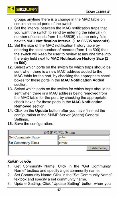
10. Set the interval between the MAC notification traps that you want the switch to send by entering the interval (in number of seconds from 1 to 65535) into the entry field next to MAC Notification Interval (1 to 65535 seconds).
11. Set the size of the MAC notification history table by entering the total number of records (from 1 to 500) that the switch will keep for user to review at any one time into the entry field next to MAC Notification History Size (1 to 500).
12. Select which ports on the switch for which traps should be sent when there is a new MAC address added to the MAC table for the port, by checking the appropriate check boxes for these ports in the MAC Notification Added section.
13. Select which ports on the switch for which traps should be sent when there is a MAC address being removed from the MAC table for the port, by checking the appropriate check boxes for these ports in the MAC Notification Removed section.
14. Click on the Update button after you have finished the configuration of the SNMP Server (Agent) General Settings.
15. Save the configuration.
SNMP v1/v2c 1. Get Community Name: Click in the “Get Community
Name” textbox and specify a get community name. 2. Set Community Name: Click in the “Set Community Name”
textbox and specify a set community name. 3. Update Setting: Click “Update Setting” button when you

XSNet C6108SW
68
have finished SNMP V1/V2c Setting.
SNMP v3 Add User: 1. Add User: Click “Add User” button. The “SNMP V3
Setting” window appears. 2. SNMP Version: Click “SNMP Version” drop-down menu
from “SNMP Version” drop-down list to choose “SNMPv3 No-Auth”, “SNMPv3 Auth-MD5”, “SNMPv3 Auth-SHA”, “SNMPv3 Priv Auth-MD5”, or “SNMPv3 Priv Auth-SHA”. SNMPv3 No-Auth: Add a user using SNMP v3 without
authentication. SNMPv3 Auth-MD5: Add a user using SNMP v3 with
authentication. Click in the “Auth. Password” textbox and specify an authentication password.
SNMPv3 Auth-SHA: Add a user using SNMP v3 with authentication. Click in the “Auth. Password” textbox and specify an authentication password.

XSNet C6108SW
69
SNMPv3 Priv Auth-MD5: Add a user using SNMP v3 with authentication and privacy. Click in the “Auth. Password” textbox and specify an authentication password. Click in the “Privacy PassPhrase” textbox and specify a privacy pass phrase.
SNMPv3 Priv Auth-SHA: Add a user using SNMP v3 with authentication and privacy. Click in the “Auth. Password” textbox and specify an authentication password. Click in the “Privacy PassPhrase” textbox and specify a privacy pass phrase.
3. User Name: Click in the “User Name” textbox and specify a user name for user using SNMP v3.
4. Access Mode: Click “Access Mode” drop-down menu from “Access Mode” drop-down list to choose “Read Only” or “Read/Write”. Read Only: Add a user using SNMP v3 with read-only
access mode. Read/Write: Add an user using SNMP v3 with
read-write access mode 5. Sumit: Click “Sumit” button when you have finished
SNMP V3 Setting.

XSNet C6108SW
70
802.1x
Radius Configuration By default, the 802.1X function is globally disabled on the switch. If you want to use the 802.1X port based security on a port, you must enable it globally on the switch first, and then enable it on a per port basis. To enable the 802.1X function globally on the switch: 1. Choose enable from the drop down list next to Radius
Status 2. Click on the Update Setting button.
Adding a Radius Server Next, you will need to configure the settings that the switch will need in order to connect to a RADIUS server. 1. Click on the Add Radius button (see Error! Reference
ource not found.).

XSNet C6108SW
71
2. Next, enter the IP address of the RADIUS server that the switch will use in order to authenticate in the entry field next to Radius Server IP.
3. Enter the password for RADIUS server in the entry field next to Secret Key.
4. Optionally, the UDP port number for the RADIUS server (if it is different from the standard default 1812) can be changed. To do this, enter the port number in the entry field next to Radius Server Port.
5. Next, you can choose to configure the minimum time that the switch must wait, before it is allowed to retransmit a message to the RADIUS server due to no response. To do this, enter the number of seconds that the switch must wait (between 1 and 1000 seconds) into the entry field next to Timeout <1-1000> .
6. Next, you can choose to configure the maximum number of times that the switch can attempt to retransmit a message to the RADIUS server. To do this, please enter a number (from 1 to 100) into the entry field next to Retransmit.
7. Click on the Submit button.

XSNet C6108SW
72
Port Authentication 1. Interface: Click “Interface” drop-down menu from
“Interface” drop-down list to choose the port to be set port-based authentication.
2. Authentication State: Click “Authentication State” drop-down menu from “Authentication State” drop-down list to choose “Enable” or “Disable” to enable or disable authentication state.
3. Port Control: Click “Port Control” drop-down menu from “Port Control” drop-down list to choose “Auto”, “Force Authorized”, or “Force Unauthorized” to force a port state. “Auto” specifies to enable authentication on port. “Force Authorized” specifies to force a port to always be in an authorized state. “Force Unauthorized” specifies to force a port to always be in an unauthorized state.
4. Periodic Reauthentication: Click “Periodic Reauthentication” drop-down menu from “Periodic Reauthentication” drop-down list to choose “Enable” or “Disable” to enable or disable periodic reauthentication.
5. Reauthentication Period <1-4294967295>: Click in the

XSNet C6108SW
73
“Reauthentication Period” textbox and specify the seconds between reauthorization attempts. The default time is 3600 seconds.
6. Update Setting: Click “Update Setting” button when you have finished port-based authentication setting.
LLDP
Enable/Disable LLDP To enable LLDP on the switch: 1. Select Enable or Disable from the Drop Down box in the
LLDP field of the LLDP Transmit Settings box. 2. Click on the Update Settings button. 3. Save the configuration. Holdtime Multiplier The Holdtime multiplier for transmit TTL is used to compute the actual time-to-live (TTL) value used in an LLDP frame.
XSNet C6108SW
74
The TTL value is the length of time the receiving device should maintain the information in its MIB. To compute the TTL value, the system multiplies the LLDP transmit (TX) interval by the holdtime multiplier. For example, if the LLDP transmit (TX) interval is 30 and the holdtime multiplier for TTL is 4, then the value 120 is encoded in the TTL field in the LLDP header. To adjust the Holdtime multiplier: 1. Enter a numeric value between 2 and 10 (default is 4) in
the Holdtime Multiplier text box. 2. Click on the Update Settings button. The TX Interval setting adjusts the time that LLDP information is transmitted by the switch. Values can range from 5 to 32768 seconds (default is 30 seconds). To adjust the TX Interval setting: 1. Enter a numeric value between 5 and 32768 (default is 30)
in the TX Interval text box. 2. Click on the Update Settings button. 3. Save the configuration. Global TLV Setting The global TLV (Time – Length – Value) settings are advertised by the switch to other LLDP devices. To enable specific TLVs for the switch: 1. Select the check box for each TLV that is to be enabled or
select the checkbox for the All option which will enable all TLVs for the switch.
2. Click on the Update Settings button. 3. Save the configuration.

XSNet C6108SW
75
LLDP Ports Settings LLDP Ports Settings allows the individual ports on the switch to be configured for LLDP independently of one another. Each port can be configured to transmit LLDP information, receive LLDP information, and notify (via SNMP or Syslog) if there are changes in the LLDP information received from neighboring devices. Enabling LLDP transmission for a specific Port To enable the transmission of LLDP information for a specific port: 1. Select Enable from the Drop Down box under the
Transmit field for each port for which the transmission of LLDP information should be enabled.
2. Click on the Submit button.
Enabling LLDP Reception for a specific Port To enable the reception of LLDP information for a specific port: 1. Select Enable from the Drop Down box under the
Receive field for each port for which the reception of LLDP information should be enabled.
2. Click on the Submit button.

XSNet C6108SW
76
Enabling Notifications To enable notification whenever a port receives changed LLDP information: 1. Select Enable from the Drop Down box under the Notify
field for each port that should send a notification whenever received LLDP information changes.
2. Click on the Submit button 3. Save the configuration after making changes shown on
this page.
LLDP Neighbors LLDP Neighbors is a read-only page (see Error! Reference ource not found.) that will display all the LLDP capable devices detected by the switch. The following information about connected LLDP-enabled devices is displayed in a tabular format. The columns displayed are:
Port – The local switch port to which the remote device is connected.
Chassis ID – The MAC address of the remote device.
Port ID – The port number of the remote device.
IP Address – The management IP address of the remote device.
TTL – Time to Live, the amount time remaining before the remote device’s LLDP is aged-out from the switch.

XSNet C6108SW
77
LLDP Statistics This is a read-only page that displays LLDP device statistics and LLDP statistics on a per-port basis. The information collected on this page includes:
Port – switch port number.
TX Total – Total LLDP packets sent.
RX Total – Total LLDP packets received.
Discards – Number of LLDP packets discarded.
Errors – LLDP errors.
Ageout – LLDP information that has been aged out by the switch.
TLV Discards – TLV information discarded
TLV Unknown – TLV information that is unknown

XSNet C6108SW
78
ROUTING
Creating a Static Route 1. In the Destination field, enter the IP address of the final
destination. 2. Choose either Prefix Length or Mask, and enter the
corresponding number in the field below. 3. Select Interface or Next Hop. For interface, choose the
switch VLAN port to be used for the static route. For Next Hop, enter the IP address of the closest router or switch to be used.
4. Enter the Administrative Distance. 5. Click Add to create the static route. You can delete existing static routes by selecting an entry and clicking the Delete button.
XSNet C6108SW
79
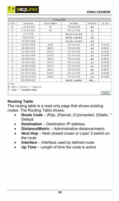
Routing Table The routing table is a read-only page that shows existing routes. The Routing Table shows:
Route Code – (R)ip, (K)ernel, (C)onnected, (S)tatic, * Default
Destination – Destination IP address
Distance/Metric – Administrative distance/metric.
Next Hop – Next closest router or Layer 3 switch on the route
Interface – Interface used by defined route
Up Time – Length of time the route is active

XSNet C6108SW
80
Route Map Route Maps can be used for both redistribution and policy routing, and thus give you more control over the way packets move around the network. To create a new Route Map:
1. Enter a descriptive name in the Name field. 2. Select the type of Route Map – Permit or Deny. 3. Under Match Clause, choose the data item that the
map will match in order for the route to take effect: Interface, Metric, IP address, or None.
4. Select the destination network or next hop router address to match an ACL, in an ACL is to be used.
5. Select the Set Clause data type, and enter the metric or next hop results.
6. Click Add to create the Route Map.
XSNet C6108SW
81
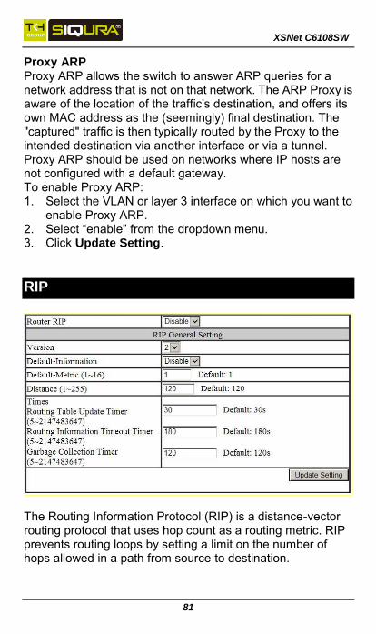
Proxy ARP Proxy ARP allows the switch to answer ARP queries for a network address that is not on that network. The ARP Proxy is aware of the location of the traffic's destination, and offers its own MAC address as the (seemingly) final destination. The "captured" traffic is then typically routed by the Proxy to the intended destination via another interface or via a tunnel. Proxy ARP should be used on networks where IP hosts are not configured with a default gateway. To enable Proxy ARP: 1. Select the VLAN or layer 3 interface on which you want to
enable Proxy ARP. 2. Select “enable” from the dropdown menu. 3. Click Update Setting.
RIP
The Routing Information Protocol (RIP) is a distance-vector routing protocol that uses hop count as a routing metric. RIP prevents routing loops by setting a limit on the number of hops allowed in a path from source to destination.

XSNet C6108SW
82
RIP General Settings To enable and configure RIP on the managed switch: 1. Set the Router RIP field to Enable. 2. Choose RIP version 1 or 2. 3. Set the Default Metric value in the range of 1 to 16. 4. Set the Distance from 1 to 255 (Default value is 120) 5. Set the timings for the Routing Table Update Timer, the
Routing Information Timeout Timer, and the Garbage Collection Timer (Default values are 30, 180, and 120 seconds respectively).
6. Click Update Setting to start RIP with the set values.
RIP Port Settings To configure RIP port settings: 1. Select the interface. 2. Set the RIP receive version (1, 2, or both) 3. Set Receive packets to enable or disable 4. Set the Send Version to 1, 2, 1-compatible, or both. 5. Set Send Packet to Enable or Disable. 6. For the Split Horizon Field, select enable, disable, or
poison reverse. 7. Set the Authentication Mode to disable, MD5, or simple
password. 8. If the Authentication Mode is MD5 or Simple Password,
set the Authentication Key (1 – 16 characters). 9. Click Update Setting
XSNet C6108SW
83
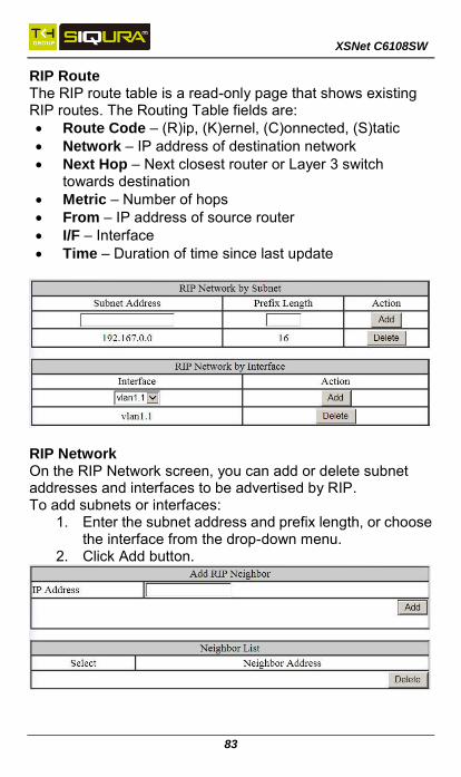
RIP Route The RIP route table is a read-only page that shows existing RIP routes. The Routing Table fields are:
Route Code – (R)ip, (K)ernel, (C)onnected, (S)tatic
Network – IP address of destination network
Next Hop – Next closest router or Layer 3 switch towards destination
Metric – Number of hops
From – IP address of source router
I/F – Interface
Time – Duration of time since last update
RIP Network On the RIP Network screen, you can add or delete subnet addresses and interfaces to be advertised by RIP. To add subnets or interfaces:
1. Enter the subnet address and prefix length, or choose the interface from the drop-down menu.
2. Click Add button.

XSNet C6108SW
84
RIP Neighbor The RIP Neighbor screen is used to add/delete RIP neighbor IP addresses. Add the IP address of neighboring routers and layer 3 switches, and click Add. Select existing neighbors from the list at the bottom and click Delete to remove them.
Add or Delete RIP Passive Interface On the RIP Passive screen, you can select an interface to be “passive,” that is, to prevent the RIP routing process from sending multicast/broadcast updates on that interface. Select the desired interface from the drop-down menu and click Add to make that interface passive. You can select and delete passive interfaces from the Passive Interface List at the bottom. Doing so will return them to send multicast/broadcast updates normally.
RIP Redistribute Redistribution is using a routing protocol to advertise routes that have been learned by another routing protocol, static routes, or directly connected routes. To add an item to the redistribute list, select the protocol (connected or static), a route map that has been previously defined, and the desired metric, then click the Add button.
XSNet C6108SW
85
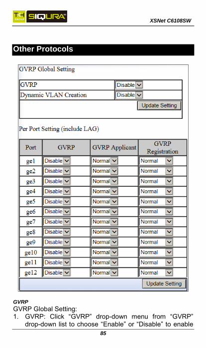
Other Protocols
GVRP
GVRP Global Setting: 1. GVRP: Click “GVRP” drop-down menu from “GVRP”
drop-down list to choose “Enable” or “Disable” to enable

XSNet C6108SW
86
or disable GVRP (GARP VLAN Registration Protocol). 2. Dynamic VLAN creation: Click “Dynamic VLAN creation”
drop-down menu from “Dynamic VLAN creation” drop-down list to choose “Enable” or “Disable” to enable or disable Dynamic VLAN creation. GARP (Generic Attribute Registration Protocol) provides IEEE802.1Q compliant VLAN pruning and dynamic VLAN creation on IEEE802.1Q trunk ports.
3. Update Setting: Click “Update Setting” button when you have finished GVRP Global Setting.
Per port setting (include LAG): 1. GVRP: Click “GVRP” drop-down menu from “GVRP”
drop-down list to choose “Enable” or “Disable” to enable or disable GVRP for the port.
2. GVRP applicant: Click “GVRP applicant” drop-down menu from “GVRP applicant” drop-down list to choose “Active” or “Normal” to the port. Ports in the GVRP active applicant state send GVRP VLAN declarations when they are in the STP (Spanning Tree Protocol) blocking state, which prevents the STP bridge protocol data units (BPDUs) from being pruned from the other port. Ports in the GVRP normal applicant state do not declare GVRP VLANs when in the STP blocking state.
3. GVRP registration: Click “GVRP registration” drop-down menu from “GVRP registration” drop-down list to choose “Enable” or “Disable” to enable or disable GVRP registration to the port. Configuring an IEEE802.1Q trunk port in registration mode allows dynamic creation (if dynamic VLAN creation is enabled), registration, and deregistration of VLANs on the trunk port.
4. Update Setting: Click “Update Setting” button when you have finished Per port setting.

XSNet C6108SW
87
IGMP Snooping 1. IGMP mode: Click “IGMP mode” drop-down menu from
“IGMP mode” drop-down list to choose “Disable”, “Passive”, or “querier” for the switch. Disable: Disable IGMP on the switch. Passive: The switch with only multicast-data-forwarding capability. Querier: The switch acts as the querier for the network. There is only one querier on a network at any time.
2. Update Setting: Click “Update Setting” button when you have finished IGMP mode settings.
3. VLAN ID: Click “VLAN ID” drop-down menu from “VLAN ID” drop-down list to choose the VLAN under

XSNet C6108SW
88
configuration for the switch. 4. IGMP version: Click “IGMP version” drop-down menu
from “IGMP version” drop-down list to choose “1”, “2”, or “3” for the switch.
5. Fast-leave: Click “fast-leave” drop-down menu from “fast-leave” drop-down list to choose “Enable” or “Disable” for the switch. Enable this function will allow members of a multicast group to leave the group immediately when an IGMP Leave Report Packet is received by the Switch.
IGMP querier: 1. Query-interval: Click in the “query-interval” textbox and
specify a new number from 1 ~ 18000. The query-interval field is used to set the time (in seconds) between transmitting IGMP queries. Entries between 1 and 18000 seconds are allowed. Default = 125.
2. Max-response-time: Click in the “max-response-time” textbox and specify a new number from 1 ~ 124. This determines the maximum amount of time in seconds allowed before sending an IGMP response report. The max-response-time field allows an entry between 1 and 124 (seconds). Default = 10.
IGMP passive snooping: 1. Report suppression: Click “report suppression”
drop-down menu from “report suppression” drop-down list to choose “Enable” or “Disable” for the switch. Use this command to enable report suppression for IGMP version 1 and version 2. Report suppression does not apply to IGMP version 3, and is turned off by default for IGMP version 1 and IGMP version 2 reports. The switch uses IGMP report suppression to forward only one IGMP report per multicast router query to multicast devices. When IGMP router suppression is enabled, the switch sends the first IGMP report from all hosts for a group to all the multicast routers. The switch does not send the remaining IGMP reports for the group to the multicast routers. This feature prevents duplicate reports from being sent to the multicast devices.

XSNet C6108SW
89
2. Update Setting: Click “Update Setting” button when you have finished IGMP Snooping.
Passive Mode Forwarding Port: 1. Port: Choose the port to set the port as passive mode
forwarding port. The Switch (in IGMP passive mode) will forward unknown multicast packets to passive mode forwarding port before receiving IGMP query.
2. Update Setting: Click “Update Setting” button when you have finished Passive Mode Forwarding Port setting.
NTP NTP Setting: 1. NTP Status: Click “NTP Status” drop-down menu from
“NTP Status” drop-down list to choose “Enable” or

XSNet C6108SW
90
“Disable” to enable or disable NTP for the Switch. 2. NTP Server (IP Address or Domain name): Click in the
“NTP Server” textbox and specify the IP address or Domain name of NTP server.
3. Sync Time: Click “Sync Time” button to synchronize time with NTP server.
4. Time Zone: Click “Tmie Zone” drop-down menu from “Tmie Zone” drop-down list to set time zone.
5. Polling Interval (1-10080 min): Click in the “Polling Interval” textbox and specify the polling interval.
6. Update Setting: Click “Update Setting” button when you have finished NTP Setting.
Daylight Saving Setting: 1. Daylight Saving Mode: Click "Daylight Saving Mode"
drop-down menu from "Daylight Saving Mode" drop-down list to choose "Disable", "Weekday", or "Date" to choose disable, weekday, or date daylight saving for the Switch.
2. Time Set Offset (1-1440 min): Click in the "Time Set Offset" textbox and specify the offset time of daylight saving. For example enter 60 for one hour offset.
3. Name of Daylight Saving Tmiezone: Click in the "Name of Daylight Saving Tmiezone" textbox and specify the daylight saving timezone. This can be any given name in 14-character alpha-numeric characters. Enter the Name of Daylight Saving Timezone using the following example:
EDT - East Daylight Saving Time Zone. CDT - Central Daylight-Saving Time Zone. MDT - Mountain Daylight-Saving Time Zone. PDT - Pacific Daylight-Saving Time Zone. ADT - Alaska Daylight-Saving Time Zone.
4. Weekday: Specify the daylight saving period.
Month: Click "Month" drop-down menu from "Month" drop-down list to choose from January to December.
Week: <1-5> Specifies starting/ending week of daylight savings time.
Day: Click "Day" drop-down menu from "Day"
XSNet C6108SW
91
drop-down list to choose from Sunday to Saturday.
Hour: <0-23> Specifies from 0 to 23.
Minute: <0-59> Specifies from 0 to 59. 5. Date: Specify the daylight saving period.
Month: Click "Month" drop-down menu from "Month" drop-down list to choose from January to December.
Day: <1-31> Specifies from 1 to 31.
Hour: <0-23> Specifies from 0 to 23.
Minute: <0-59> Specifies from 0 to 59. 6. Update Setting: Click "Update Setting" button when you
have finished Daylight Saving Setting.
Note: The “Week”, “Hour”, “Minute”, and “Day” fields do not accept alphabetic characters (Like Jan, Feb, Sun, Mon). They only accept numerical input.

XSNet C6108SW
92
GMRP GMRP Global Setting: 1. GMRP: Click “GMRP” drop-down menu from “GMRP”
drop-down list to choose “Enable” or “Disable” to enable or disable GMRP.
2. Update Setting: Click “Update Setting” button when you have finished GMRP Global Setting.
Per port setting (include LAG): 1. GMRP: Click “GMRP” drop-down menu from “GMRP”

XSNet C6108SW
93
drop-down list to choose “Enable” or “Disable” to enable or disable GMRP for the port.
2. GMRP registration: Click “GMRP registration” drop-down menu from “GMRP registration” drop-down list to choose “Normal”, “Fixed” or “Forbidden” to specify GMRP registration to the port. Normal specifies dynamic GMRP multicast registration and deregistration on the port. Fixed specifies the multicast groups currently registered on the switch are applied to the port, but any subsequent registrations or deregistrations do not affect the port. Any registered multicast groups on the port are not deregistered based on the GARP timers. Forbidden specifies that all GMRP multicasts are deregistered, and prevent any further GMRP multicast registration on the port.
3. GMRP Forward All: Click “GMRP Forward All” drop-down menu from “GMRP Forward All” drop-down list to choose “Enable” or “Disable” to enable or disable GMRP forwarding to the port.
4. Update Setting: Click “Update Setting” button when you have finished Per port setting.

XSNet C6108SW
94
DHCP Server 1. DHCP Binding Table: Click on “DHCP Binding Table” to
show DHCP Binding Table. Click “Refresh” button to refresh DHCP Binding Table. Click on “DHCP General Setting” to back to DHCP General Setting.
2. DHCP Server Status: Click “DHCP Server Status” drop-down menu from “DHCP Server Status” drop-down list to choose “Disable”, “Default VLAN 1”, or other VLAN.
3. Start IP: Click in the “Start IP” textbox and specify the default Start IP for the DHCP Server.
4. End IP: Click in the “End IP” textbox and specify the default End IP for the DHCP Server.
5. Subnet-mask: Click in the “Subnet-mask” textbox and specify the default subnet mask for the DHCP Server.
6. Gateway: Click in the “Gateway” textbox and specify the default gateway for the DHCP Server.
7. Primary DNS: Click in the “Primary DNS” textbox and specify the default primary DNS for the DHCP Server.
8. Secondary DNS: Click in the “Secondary DNS” textbox and specify the default secondary DNS for the DHCP Server.
9. Lease time: Click in the “Lease time” textbox and specify the default lease time for the DHCP Server.
10. Update Setting: Click “Update Setting” button when you have finished DHCP Server General Setting.
Note: You will need to disable and re-enable DHCP Server for any DHCP Server related changes to take effect.
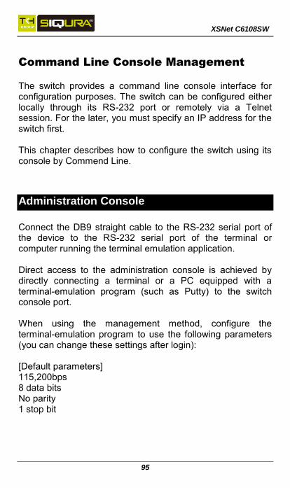
XSNet C6108SW
95
Command Line Console Management
The switch provides a command line console interface for configuration purposes. The switch can be configured either locally through its RS-232 port or remotely via a Telnet session. For the later, you must specify an IP address for the switch first. This chapter describes how to configure the switch using its console by Commend Line.
Administration Console
Connect the DB9 straight cable to the RS-232 serial port of the device to the RS-232 serial port of the terminal or computer running the terminal emulation application. Direct access to the administration console is achieved by directly connecting a terminal or a PC equipped with a terminal-emulation program (such as Putty) to the switch console port. When using the management method, configure the terminal-emulation program to use the following parameters (you can change these settings after login): [Default parameters] 115,200bps 8 data bits No parity 1 stop bit

XSNet C6108SW
96
Navigating the CLI Hierarchy
The CLI is organized into a hierarchy of command
modes. The basic modes are User exec mode,
Privileged exec mode, and Global configuration mode.
There are also other modes, specific to certain
configurations. Each mode has its own group of
commands for a specific purpose. Below are the CLI
commands needed to enter a specific mode:
switch_a> ← User exec mode
switch_a>enable
switch_a# ← Privileged exec mode
switch_a#configure terminal
switch_a(config) ← Global configuration mode
switch_a(config) spanning-tree mst configuration
switch_a(config-mst)# ← MSTP configuration mode
switch_a(config)# interface fe1
switch_a(config-if)# ← Interface configuration mode
switch_a(config)#vlan database
switch_a(config-vlan)# ← VLAN database configuration
mode
Saving a Configuration from the CLI
Example:
switch_a>enable
switch_a#write memory
Building configuration.....
[OK]
switch_a#>

XSNet C6108SW
97
CLI Keyboard Shortcuts Ctrl + a: place cursor at the beginning of a line
Ctrl + b: backspace one character
Ctrl + d: delete one character
Ctrl + e: place cursor at the end of the line
Ctrl + f: move cursor forward one character
Ctrl + k: delete from the current position to the end of the line
Ctrl + l: redraw the command line
Ctrl + n: display the next line in the history
Ctrl + p: display the previous line in the history
Ctrl + u: delete entire line and place cursor at start of prompt
Ctrl + w: delete one word back
At any time, enter <?> to show a list of the commands available.
switch_a>?
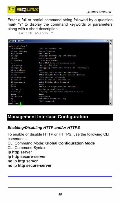
XSNet C6108SW
98
Enter a full or partial command string followed by a question mark “?” to display the command keywords or parameters along with a short description.
switch_a>show ?
Management Interface Configuration
Enabling/Disabling HTTP and/or HTTPS
To enable or disable HTTP or HTTPS, use the following CLI commands: CLI Command Mode: Global Configuration Mode CLI Command Syntax: ip http server ip http secure-server no ip http server no ip http secure-server
XSNet C6108SW
99
Enabling/Disabling Telnet
To enable or disable telnet, use the following CLI commands: CLI Command Mode: Global Configuration Mode CLI Command Syntax: ip telnet no ip telnet Example: Enabling Telnet: switch_a(config)#ip telnet
switch_a(config)#q
switch_a#write memory
Building configuration.....
[OK]
Note: If using Telnet to run the CLI Commands that disable telnet you will lose your connection. To Disable Telnet using the CLI, use SSH or the RS-232 Console port on the switch.
Enabling/Disabling SSH
To enable or disable SSH, use the following CLI commands: CLI Command Mode: Global Configuration Mode CLI Command Syntax: ip ssh no ip ssh Note: If using SSH to run the CLI Commands that disable SSH you will lose your connection. To Disable SSH using the CLI, use Telnet or the RS-232 Console port on the switch.
System
System Name/Password System Name To set the system name on a switch, use the following CLI commands: CLI Command Mode: Global Configuration Mode

XSNet C6108SW
100
CLI Command Syntax: hostname <name> no hostname Example 1: Setting a Hostname to “switch_a” switch_a(config)#hostname switch_a
Note: Using the no hostname command will reset the switch name to the default “switch_a.” Password To enable a password on a switch, use the following CLI commands: CLI Command Mode: Global Configuration Mode CLI Command Syntax: enable password <password> Example: Setting switch password to “mypassword” switch_a(config)#enable password mypassword
IP Address CLI Command Mode: Global Configuration Mode CLI Command Syntax: ip address <A.B.C.D/M> (IP Address/Mask e.g. 10.0.0.1/8) no ip address Example 1: Assigning an IP address of 192.168.1.1 with subnet mask of 255.255.255.0 switch_a(config)#ip address 192.168.1.1/24
Enable/Disable DHCP Client on a VLAN CLI Command Mode: Interface Configuration Mode CLI Command Syntax: get ip dhcp enable no get ip dhcp enable Usage Example – Enable DHCP Client on VLAN2: switch_a(config)#interface vlan1.2
switch_a(config-if)#get ip dhcp enable
switch_a(config-if)#q
Enable/Disable Static IP on a VLAN
XSNet C6108SW
101
To set the IP address, use the following CLI commands: CLI Command Mode: Interface Configuration Mode CLI Command Syntax: ip address <A.B.C.D> no ip address <A.B.C.D> Usage Example 1 – Enable Static IP of 192.168.1.11 with subnet mask 255.255.255.0 on VLAN2: switch_a(config)#interface vlan1.2
switch_a(config-if)#ip address 192.168.1.11/24
switch_a(config-if)#q
Usage Example 2 – Disable Static IP on VLAN2: switch_a(config)#interface vlan1.2
switch_a(config-if)#no ip address
switch_a(config-if)#q
Default Gateway: CLI Command Mode: Global Configuration Mode CLI Command Syntax: ip default-gateway <A.B.C.D> no ip default gateway Example 1: Setting the default gateway to 192.168.1.254 switch_a(config)#ip default-gateway
192.168.1.254
switch_a(config)#q
switch_a#write memory
Building configuration.....
[OK]
Example 2: Removing the Gateway switch_a(config)#no ip default-gateway
switch_a(config)#q
switch_a#write memory
Building configuration.....
[OK]
DNS Server: CLI Command Mode: Global Configuration Mode

XSNet C6108SW
102
CLI Command Syntax: ip dns <A.B.C.D> no ip dns Example: Set Domain name server to 192.168.1.253 switch_a(config)#ip dns 192.168.1.253
switch_a(config)#q
switch_a#write memory
Building configuration.....
[OK]
Example 2: Remove a DNS IP Address switch_a(config)#no ip dns
switch_a(config)#q
switch_a#write memory
Building configuration.....
[OK]
Save Configuration CLI Command Mode: Global Configuration Mode CLI Command Syntax: write memory
Restore Default Settings CLI Command Mode: Global Configuration Mode CLI Command Syntax: restore default
Load Configuration from a TFTP Server CLI Command Mode: Privileged Exec Mode CLI Command Syntax: install config-file <tftpserver_ipaddress> <filename> Example: Loading a Configuration from TFTP server on 192.168.1.100, where configuration file is file_name.tgz switch_a#install config-file 192.168.1.100
file_name.tgz
Save Configuration to a TFTP Server CLI Command Mode: Privileged Exec Mode CLI Command Syntax: write config-file <tftpserver_ipaddress> <filename>

XSNet C6108SW
103
Auto Save Configuration CLI Command Mode: Global Configuration Mode CLI Command Syntax: service auto-config enable no service auto-config enable service auto-config interval <number> Example 1: Enabling Auto Save with interval of 10 seconds switch_a(config)#service auto-config enable
switch_a(config)#service auto-config interval
10
Firmware Upgrade To display the current primary and alternate firmware versions: CLI Command Mode: Privileged Exec Mode CLI Command Syntax: show firmware To update firmware from a TFTP server: CLI Command Mode: Privileged Exec Mode CLI Command Syntax: install image <tftpserver_ipaddress> <filename> Note: Depending on the firmware being loaded, the extension may not be .tgz. The Switch does not use the extension to validate firmware.
Booting From Alternate (Backup) Firmware Under certain circumstances, such as when there is a loss of power during an upgrade, the firmware build on the switch can become unstable. To prevent the switch from becoming unbootable in this situation, there are two firmware images stored on the switch: primary and backup. If the primary firmware image becomes unstable, the switch will detect it automatically and boot from the backup image on the next boot. You can also manually boot from the backup firmware image. To do so, follow these steps:

XSNet C6108SW
104
1. Connect to the switch’s RS-232 port with a terminal emulator.
2. Power cycle the switch (turn the power off and then on). 3. While the switch is rebooting, hold down Ctrl + C. This
will cause the switch to enter CFE mode. The prompt should look like this: CFE_1.5>
4. Use the command boot_image0 and boot_image1 to manually boot from the primary and alternate firmware images respectively. Future boots will be from the image selected with this command.
Reboot Switch CLI Command Mode: Privileged Exec Mode CLI Command Syntax: reload
Logout from the CLI CLI Command Mode: User Exec Mode or Privileged Exec Mode CLI Command Syntax: logout
Diagnostics
System Log CLI Command Mode: User Exec Mode or Privileged Exec Mode CLI Command Syntax: show system-log
Enable/Disable Remote Logging CLI Command Mode: Global Configuration Mode CLI Command Syntax: remote-log enable no remote-log enable

XSNet C6108SW
105
Add/Delete a Remote Logging Host CLI Command Mode: Global Configuration Mode CLI Command Syntax: remote-log add <ip_address> remote-log del <ip_address> remote-log del all Example 1: Add a Remote Logging Host at 192.168.1.100 switch_a(config)#remote-log add 192.168.1.100
ARP Table CLI Command Mode: Global Configuration Mode CLI Command Syntax: show arp-table
Route Table CLI Command Mode: Privileged Exec Mode CLI Command Syntax: show route-table Dying Gasp Show current primary and secondary Dying Gasp settings CLI Command Mode: Privileged Exec Mode CLI Command Syntax: show dying-gasp status Set primary and secondary Dying Gasp messages CLI Command Mode: Global Configuration Mode CLI Command Syntax: dying-gasp primary <delivery_method> secondary <delivery_method>

XSNet C6108SW
106
Port
Setting the Port Description CLI Command Mode: Interface Configuration Mode CLI Command Syntax: description <description text>
Enable or Disable a Port CLI Command Mode: Interface Configuration Mode CLI Command Syntax: shutdown no shutdown
Setting the Port Speed CLI Command Mode: Interface Configuration Mode CLI Command Syntax: bandwidth <1-10000000000 bits> (usable units : k, m, g) Usage Example: switch_a(config-if)#bandwidth 100m
Setting Port Duplex CLI Command Mode: Interface Configuration Mode CLI Command Syntax: duplex <full | half | auto> Usage Example: switch_a(config-if)#duplex full
Enable or Disable Port Flow Control CLI Command Mode: Interface Configuration Mode CLI Command Syntax: flowcontrol on
Display Port Status CLI Command Mode: Privileged Exec Mode CLI Command Syntax: show interface <ifname>
Set Port Rate Control CLI Command Mode: Interface Configuration Mode CLI Command Syntax: rate-control <ingress | egress> value <value in kbps> Example:

XSNet C6108SW
107
switch_a(config-if)#rate-control ingress value
100000
Display Port RMON Statistics CLI Command Mode: Privileged Exec Mode CLI Command Syntax: show interface statistics <interface name> Usage Example: switch_a#show interface statistics ge1
Display Port VLAN Activities CLI Command Mode: Privileged Exec Mode CLI Command Syntax: show bridge interface <interface name> Usage Example: switch_a#show bridge interface fe1
Switching
Setting Ageing Time Value CLI Command Mode: Global Configuration Mode CLI Command Syntax: bridge 1 ageing-time (time in ms) Example: Set ageing time to 300ms switch_a(config)#bridge 1 ageing time 300
Enabling Port Isolation CLI Command Mode: Interface Configuration Mode CLI Command Syntax: port-isolation enable Enabling Port Block Multicast CLI Command Mode: Interface Configuration Mode CLI Command Syntax: switchport block multicast Setting Storm Control CLI Command Mode: Interface Configuration Mode CLI Command Syntax: stormcontrol <broadcast | dlf-multicast> <level>

XSNet C6108SW
108
Usage Example: switch_a(config-if)#storm-control broadcast
enable
switch_a(config-if)#storm-control level 20
Enabling Loopback Detect (Global) CLI Command Mode: Global Configuration Mode CLI Command Syntax: bridge 1 loopback-detect <enable | disable> Example: switch_a(config)#bridge 1 loopback-detect
enable
Setting the Loopback Detect Action CLI Command Mode: Global Configuration Mode CLI Command Syntax: bridge 1 loopback-detect action <err-disable | none> Example: switch_a(config)#bridge 1 loopback-detect
action errdisable
Setting the Loopback Detect Recovery Time CLI Command Mode: Global Configuration Mode CLI Command Syntax: bridge 1 loopback-detect errdisable-recovery <0-65535> Usage Example: switch_a(config)#bridge 1 loopback-detect
errdisable-recovery 30
Setting the Loopback Detect Polling Interval CLI Command Mode: Global Configuration Mode CLI Command Syntax: bridge 1 loopback-detect interval <1-65535> Usage Example: switch_a(config)#bridge 1 loopback-detect
interval 5
Enabling Loopback Detect (Port) CLI Command Mode: Interface Configuration Mode

XSNet C6108SW
109
CLI Command Syntax: loopback-detect enable
Enable or Disable Storm-Detect CLI Command Mode: Global Configuration Mode CLI Command Syntax: bridge 1 storm-detect errdisable no bridge 1 storm-detect errdisable Default: Disabled
Set Storm-Detect Interval CLI Command Mode: Global Configuration Mode CLI Command Syntax: bridge 1 storm-detect interval <2-65535> Default: 10 Example: switch_a(config)# bridge 1 storm-detect
interval 10
Set Storm-Detect Recovery Time CLI Command Mode: Global Configuration Mode CLI Command Syntax: bridge 1 storm-detect errdisable-recovery <0-65535> Default: 0 No errdisable recovery. Example: switch_a(config)# bridge 1 storm-detect
errdisable-recovery 60
Storm Detect Packet Type Enable this port’s storm detect by detect number of broadcast or broadcast plus multicast packets per second. Unit is packets per second. Set to 0 to disable this feature. To set the storm-detect packet type use the following CLI commands: CLI Command Mode: Interface Configuration Mode CLI Command Syntax: storm-detect (bc | mc-bc) pps <0-100000> bc = broadcast only mc-bc = count broadcast & multicast packets together. Default: 0 (Disabled)

XSNet C6108SW
110
Usage Example 1 – Enabling Multicast + Broadcast: switch_a(config-if)#storm-detect mc-bc pps
50000
Usage Example 2 – Enabling Multicast + Broadcast: switch_a(config-if)#storm-detect bc pps 50000
Storm-Detect Utilization CLI Command Mode: Interface Configuration Mode CLI Command Syntax: storm-detect utilization <0-100> Default: 0 (Disabled) Example: switch_a(config-if)#storm-detect utilization
80
Disable Storm-Detect CLI Command Mode: Interface Configuration Mode CLI Command Syntax: no storm-detect port enable
Adding a MAC Address for Static-MAC-Entry Forwarding CLI Command Mode: Global Configuration Mode CLI Command Syntax: bridge 1 address <mac address> forward <interface> vlan <vlan id> Example: switch_a(config)# bridge 1 address
00e0.abcd.1245 forward fe1 vlan 1
Discard a Static MAC Entry CLI Command Mode: Global Configuration Mode CLI Command Syntax: bridge 1 address <mac address> discard vlan <vlan id> Example: switch_a(config)# bridge 1 address
00e0.abcd.1245 discard vlan 1
Configuring Port Mirroring CLI Command Mode: Interface Configuration Mode CLI Command Syntax: mirror interface <interface> direction <both | tx | rx>
XSNet C6108SW
111
Example: switch_a(config-if)#mirror interface fe2
direction both
Enabling a Link State Tracking Group CLI Command Mode: Global Configuration Mode CLI Command Syntax: link state track <group #> Example: switch_a(config)# link state track 4
Assigning a Port to a Link State Tracking Group CLI Command Mode: Interface Configuration Mode CLI Command Syntax: link state group <group #> <upstream | downstream> Usage Example: switch_a(config-if)# link state group 4
downstream
Trunking
Adding an Interface to a Static Trunk CLI Command Mode: Interface Configuration Mode CLI Command Syntax: static-channel-group <static channel> (1-6 for 100Mbps, 7-8 for 1Gbps ports) Usage Example: switch_a(config-if)#static-channel-group 1
Adding an Interface to a LACP Trunk CLI Command Mode: Interface Configuration Mode CLI Command Syntax: channel-group <LACP Channel> mode <active | passive> (LACP Channel is 1-6 for 100Mbps, 7-8 for 1Gbps ports) Usage Example: switch_a(config-if)#channel-group 2 mode
passive
switch_a(config-if)#q

XSNet C6108SW
112
Setting the LACP Port Priority CLI Command Mode: Interface Configuration Mode CLI Command Syntax: lacp port-priority <1 - 65535> sExample: switch_a(config-if)#lacp port-priority 1
Setting the LACP Timeout CLI Command Mode: Interface Configuration Mode CLI Command Syntax: lacp timeout <long | short> Example: switch_a(config-if)#lacp timeout long
STP / Ring
RSTP
Enabling the Spanning Tree Protocol CLI Command Mode: Global Configuration Mode CLI Command Syntax: no bridge shutdown 1 bridge 1 protocol rstp vlan-bridge
Usage Example:switch_a(config)#no bridge shutdown 1
switch_a(config)#bridge 1 protocol rstp
vlan-bridge
Bridge Priority, Max Age, Forward Delay, and Hello Time CLI Command Mode: Global Configuration Mode CLI Command Syntax: bridge 1 priority <0-61440> bridge 1 max-age <6-40> bridge 1 forward-time <4-30> bridge 1 hello-time <1-10> Usage Example: switch_a(config)#bridge 1 priority 4096

XSNet C6108SW
113
switch_a(config)#bridge 1 max-age 20
switch_a(config)#bridge 1 forward-time 15
switch_a(config)#bridge 1 hello-time 2
Modifying the Port Priority and Path Cost CLI Command Mode: Interface Configuration Mode CLI Command Syntax: bridge-group 1 path-cost <1-200000000> bridge-group 1 priority <0-240> Usage Example: switch_a(config-if)#bridge-group 1 path-cost
200000
switch_a(config-if)#bridge-group 1 priority 128
Manually Setting a Port to be a Shared or Point to Point Link CLI Command Mode: Interface Configuration Mode CLI Command Syntax: spanning-tree link-type point-to-point spanning-tree link-type shared Example 1: Setting port 1 to be point-to-point: switch_a(config-if)#spanning-tree link-type
point-to-point
Example 2: Setting port 1 to be shared: switch_a(config-if)#spanning-tree link-type
shared
Enabling/Disabling a port to be an Edge Port CLI Command Mode: Interface Configuration Mode CLI Command Syntax: spanning-tree edgeport no spanning-tree edgeport Example 1: Enabling edge port on port 1: switch_a(config-if)#spanning-tree edgeport
Example 2: Disabling edge port on port 1: switch_a(config-if)#no spanning-tree edgeport

XSNet C6108SW
114
MSTP - Enabling Spanning Tree for MSTP CLI Command Mode: Global Configuration Mode CLI Command Syntax: no bridge shutdown 1 bridge 1 protocol mstp Usage Example: switch_a(config)#no bridge shutdown 1
switch_a(config)#bridge 1 protocol mstp
Bridge Priority, Max Age, Forward Delay, and Hello Time CLI Command Mode: Global Configuration Mode CLI Command Syntax: bridge 1 priority <0-61440> bridge 1 max-age <6-40> bridge 1 forward-time <4-30> bridge 1 hello-time <1-10> Usage Example: switch_a(config)#bridge 1 priority 4096
switch_a(config)#bridge 1 max-age 20
switch_a(config)#bridge 1 forward-time 15
switch_a(config)#bridge 1 hello-time 2
CIST MAX Hops CLI Command Mode: Global Configuration Mode CLI Command Syntax: bridge 1 max-hops <1-40> Usage Example: switch_a(config)#bridge 1 max-hops 20
MSTP
MSTP Regional Configuration Name and Revision Level CLI Command Mode: MSTP Configuration Mode CLI Command Syntax: bridge 1 region <region_name> bridge 1 revision <revision_number> Usage Example: switch_a(config)#spanning-tree mst
configuration

XSNet C6108SW
115
switch_a(config-mst)#bridge 1 region R1
switch_a(config-mst)#bridge 1 revision 0
Creating an MSTP Instance CLI Command Mode: MSTP Configuration Mode CLI Command Syntax: bridge 1 instance <1-15> vlan <vlan_ID> Example: switch_a(config)#spanning-tree mst
configuration
switch_a(config-mst)#bridge 1 instance 1 vlan 10
Setting MSTP Priority CLI Command Mode: Global Configuration Mode CLI Command Syntax: bridge 1 instance <1-15> priority <0-61440> Example: switch_a(config)#bridge 1 instance 1 priority 0
Modifying CIST Port Priority and Port Path Cost CLI Command Mode: Interface Configuration Mode (port) CLI Command Syntax: bridge-group 1 path-cost <1-200000000>; bridge-group 1 priority <0-240> Example: switch_a(config-if)#bridge-group 1 path-cost
200000
switch_a(config-if)#bridge-group 1 priority 128
Modify the MSTP Port Priority and MSTP Port Path Cost CLI Command Mode: Interface Configuration Mode CLI Command Syntax: bridge-group 1 instance <1-15> path-cost <1-200000000> bridge-group 1 instance <1-15> priority <0-240> Usage Example: switch_a(config-if)# bridge-group 1 instance 1
path-cost 20000
switch_a(config-if)# bridge-group 1 instance 1

XSNet C6108SW
116
priority 128
Adding a Port to an MSTP Instance CLI Command Mode: Interface Configuration Mode CLI Command Syntax: bridge-group 1 instance <1-15> Example: switch_a(config-if)#bridge-group 1 instance 1
IQ-Ring Commands
Enable/disable IQ Ring CLI Command Mode: Global Configuration Mode CLI Command Syntax: bridge 1 ring enable/disable Set Ring Ports CLI Command Mode: Global Configuration Mode CLI Command Syntax: ring set-port <interface1> <interface2> (interface1 and interface2 will be set as ring-port 1 and ring-port 2) Example: switch_a(config-if)# ring set-port fe2 fe3
Show Ring, Port, and All States CLI Command Mode: Privileged Exec Mode CLI Command Syntax: show ring state show ring port-state
Enable Ring Coupling CLI Command Mode: Global Configuration Mode CLI Command Syntax: (no) ring-coupling enable
Set Ring Coupling Ports CLI Command Mode: Global Configuration Mode CLI Command Syntax: ring set-coupling-port <interface1> <interface2>

XSNet C6108SW
117
Show Ring Coupling, Port Coupling, and Redundancy Pair States CLI Command Mode: Privileged Exec Mode CLI Command Syntax: show ring-coupling state show ring-coupling port-state
IQ-Chain Commands
Storm Control CLI Command Mode: Global Configuration Mode CLI Command Syntax: no bridge 1 chain-storm Example: switch_a(config)# no bridge 1 chain-storm
Configuring Chain Ports CLI Command Mode: Interface Configuration Mode CLI Command Syntax: chain port enable no chain port Usage Example 1: Enabling a chain port switch_a(config)#interface fe6
switch_a(config-if)#chain port enable
Configuring Chain Pass-Through Ports CLI Command Mode: Global Configuration Mode CLI Command Syntax: chain pass-through <port #1 port #2> no chain pass-through Example 1: Enabling chain pass-through switch_a(config)# chain pass-through fe3 fe4
Example 2: Disabling chain port pass-through switch_a(config)# no chain pass-through
Configuring Spanning Tree Advanced Settings using CLI

XSNet C6108SW
118
commands
Enabling BPDU Guard Globally CLI Command Mode: Global Configuration Mode CLI Command Syntax: bridge 1 spanning-tree portfast bpdu-guard Example: switch_a(config)# bridge 1 spanning-tree
portfast bpdu-guard
Enabling BPDU Guard on a Port CLI Command Mode: Interface Configuration Mode CLI Command Syntax: spanning-tree portfast; spanning-tree portfast bpdu-guard enable Usage Example: switch_a(config-if)#spanning-tree portfast
switch_a(config-if)#spanning-tree portfast
bpdu-guard enable
Enabling BPDU Guard Error Disable-timeout CLI Command Mode: Global Configuration Mode CLI Command Syntax: bridge 1 spanning-tree errdisable-timeout enable bridge 1 spanning-tree errdisable-timeout interval 300 Usage Example: switch_a(config)#bridge 1 spanning-tree
errdisable-timeout enable
switch_a(config)#bridge 1 spanning-tree
errdisable-timeout interval 300

XSNet C6108SW
119
VLAN
Configuring a 802.1Q VLAN CLI Command Mode: VLAN Database Configuration Mode CLI Command Syntax: switchport portbase add vlan <1 – 16> vlan <1 – 4094> bridge 1 name VLAN NAME state enable Usage Example: switch_a(config)#vlan database
switch_a(config-vlan)#vlan 100 bridge 1 name
Management state enable
switch_a(config-vlan)#vlan 200 bridge 1 name
Accounting state enable
switch_a(config-vlan)#vlan 300 bridge 1 name
Sales state enable
Configuring an IP Address for a Management VLAN CLI Command Mode: Interface Configuration Mode CLI Command Syntax: ip address IP_ADDRESS/PREFIX [e.g. 10.0.0.1/24] Usage Example: switch_a(config)#interface vlan1.100
switch_a(config-if)#ip address
192.168.100.10/24
Removing an IP Address from a Management VLAN CLI Command Mode: Interface Configuration Mode CLI Command Syntax: no ip address Usage Example: switch_a(config)#interface vlan1.100
switch_a(config-if)#no ip address
Configuring an Access Port CLI Command Mode: Interface Configuration Mode CLI Command Syntax: switchport mode access CLI Command Syntax: switchport access vlan <1 – 4094> Usage Example:

XSNet C6108SW
120
switch_a(config-if)#switchport mode access
switch_a(config-if)#switchport access vlan 100
Configuring a Trunk Port CLI Command Mode: Interface Configuration Mode CLI Command Syntax: switchport mode trunk CLI Command Syntax: switchport trunk allowed vlan add 100,200,300 CLI Command Syntax: switchport trunk native vlan 1 Usage Example: switch_a(config)#interface fe7
switch_a(config-if)#switchport mode trunk
switch_a(config-if)#switchport trunk allowed
vlan add 100,200,300
switch_a(config-if)#switchport trunk native
vlan 1

XSNet C6108SW
121
QoS
Enabling/Disabling QoS CLI Command Mode: Global Configuration Mode CLI Command Syntax: mls qos enable no mls qos Enable/Disable QoS Trust CLI Command Mode: Global Configuration Mode CLI Command Syntax: mls qos trust <cos/dscp> no qos trust Example – Enable QoS Trust: switch_a(config)# mls qos trust cos
Example – Disable QoS Trust: switch_a(config)# no mls qos trust
Configuring the Egress Expedite Queue CLI Command Mode: Global Configuration Mode CLI Command Syntax: priority-queue strict priority-queue out no priority-queue out mls qos <WRR_WTS> (4 values separated by spaces. Range is 1-20 (See the Example). Example 1 – Enable QoS Strict Priority (Queue 3) + WWR (Queue 0-2): switch_a(config)# priority-queue out
Example 2 – Disable QoS Strict Priority: switch_a(config)# no priority-queue
Example 3 – The following example specifies the bandwidth ratios of the four transmit queues, starting with queue 0, on the switch. WRR_WTS Weighted Round Robin (WRR) weights for the 4 queues (4 values separated by spaces). Range is 1-20.
XSNet C6108SW
122
switch_a(config)# wrr-queue bandwidth 1 2 4 8
802.1p Priority CLI Command Mode: Global Configuration Mode CLI Command Syntax: wrr-queue cos-map <QUEUE_ID> <COS_VALUE> Queue ID. Range is 0-3. COS_VALUE CoS values. Up to 8 values (separated by spaces). Example: The following example shows mapping CoS values 0 and 1 to queue 1 on the switch: switch_a(config)#wrr-queue cos-map 1 0 1
DSCP CLI Command Mode: Global Configuration Mode CLI Command Syntax: mls qos map dscp-queue <dscp_value> to <queue_ID> dscp_value: Up to 8 values (separated by spaces). Range is 0-63. queue_ID: Range is 0-3. Example The following example shows mapping DSCP values 0 to 3 to queue 1 on the switch: switch_a(config)# mls qos map dscp-queue 0 1 2 3 to 1
QoS Interface Commands To assign a VLAN Priority to an Interface: CLI Command Mode: Interface Configuration Mode CLI Command Syntax: user-priority <0-7>
ACL Configuration
Enabling QoS
CLI Command Mode: Global Configuration Mode CLI Command Syntax: mls qos enable Usage Example: switch_a(config)# mls qos enable

XSNet C6108SW
123
Creating a Standard IP Access List To create a new Standard IP Access List to allow or deny an IP address/range access to the switch, use the following CLI commands with the Access list ID in the range from 1 – 99, or from 1300 – 1999: CLI Command Mode: Global Configuration Mode CLI Command Syntax: ip-access-list <1-99, 1300-1999> permit <source IP> <source bit mask> ip-access-list <1-99, 1300-1999> deny <source IP> <source bit mask> ip-access-list <1-99, 1300-1999> deny any Usage Example: switch_a(config)# ip-access-list 1 permit
192.168.1.224 0.0.0.31
switch_a(config)# ip-access-list 1 deny
192.168.1.224 0.0.0.31
switch_a(config)# ip-access-list 1 deny any
Creating an Extended IP Access List To create a new Extended IP Access List to allow or deny an source IP address/range and destination IP address/range pair access to the switch, use the following CLI commands with the Access list ID in the range from 100 – 199, or from 2000 – 2699: CLI Command Mode: Global Configuration Mode CLI Command Syntax: ip-access-list <100-199, 2000-2699> permit ip <source IP> <source bit mask> <destination IP> <destination bit mask> ip-access-list <100-199, 2000-2699> deny ip <source IP> <source bit mask> <destination IP> <destination bit mask> ip-access-list <100-199, 2000-2699> deny ip any any Usage Example: switch_a(config)#ip-access-list 100 permit ip
192.168.1.224 0.0.0.31 192.168.1.224 0.0.0.31
switch_a(config)#ip-access-list 100 deny ip
192.168.1.224 0.0.0.31 192.168.1.224 0.0.0.31

XSNet C6108SW
124
switch_a(config)#ip-access-list 100 deny ip any
any
Creating a MAC Access List To create a new MAC Access List to allow or deny a source and destination Ethernet address pair access to the switch, use the CLI commands below with the Access list ID in the range from 100 – 199, or from 2000 – 2699.: CLI Command Mode: Global Configuration Mode CLI Command Syntax: mac-access-list <2000-2699> permit <source MAC address> <source bit mask> <destination MAC address> <destination bit mask> <encapsulation format: 1=Ethernet II, 2=SNAP, 4=802.3, 8=LLC> ether-type <EtherType> < EtherType bit mask> mac-access-list <2000-2699> deny <source MAC address> <source bit mask> <destination MAC address> <destination bit mask> <encapsulation format: 1=Ethernet II, 2=SNAP, 4=802.3, 8=LLC> ether-type <EtherType> < EtherType bit mask> mac-access-list <2000-2699> deny any any <encapsulation format: 1=Ethernet II, 2=SNAP, 4=802.3, 8=LLC> ether-type <EtherType> < EtherType bit mask>
Usage Example: switch_a(config)#mac-access-list 2000 permit
00e0.b321.03de 0000.0000.0000 00e0.b321.03df
0000.0000.0000 1 ether-type 800 0000
switch_a(config)#mac-access-list 2000 deny
00e0.b321.03de 0000.0000.0000 00e0.b321.03df
0000.0000.0000 1 ether-type 800 0000
switch_a(config)#mac-access-list 2000 deny any
any 1 ether-type 800 0000
Creating an ACL Class Map with Layer 4 Access List In order to create a Layer 4 Access List you must create it within an ACL Class Map. Use the CLI commands below to create an ACL Class Map together with the Layer 4 Access

XSNet C6108SW
125
List. The Layer 4 Access List only classifies the ingress packets for the ACL Policy Map that it is associated with; therefore, all packets will be allowed entry to the switch with the Layer 4 Access List. You will have to use this Access List in conjunction with another type of Access List, if you wish to filter any packet that did not match the classification rules from this Access List. Note: The bandwidth policing capabilities of the ACL Class cannot be configured here; it can only be configured during the ACL Policy Map creation or modification: CLI Command Mode: Global Configuration Mode Class Map Configuration Mode CLI Command Syntax: class-map <Class Map Name> match layer4 source-port <TCP/UDP Port number> match layer4 destination-port <TCP/UDP Port number> Usage Example: switch_a(config)#class-map FTP
switch_a(config-cmap)#match layer4
destination-port 21
switch_a(config-cmap)#q
switch_a(config)#
switch_a(config)#class-map FTP_Download
switch_a(config-cmap)#match layer4 source-port
20
Creating a ACL Class Map with an IP or MAC Access List To create a new ACL Class Map with a Standard/Extended IP Access List or a MAC Access List, you must have first created a Standard/Extended IP Access List or MAC Access List already. You can then use the CLI commands below to create a new ACL Class Map and assign one (you can only assign one Access List per Class Map) existing Standard/Extended IP Access List, or MAC Access List, to the ACL Class Map by referencing its Access list ID. Note: The bandwidth policing capabilities of the ACL Class cannot be configured here; it can only be configured during the ACL Policy Map creation or modification:

XSNet C6108SW
126
CLI Command Mode: Global Configuration Mode Class Map Configuration Mode CLI Command Syntax: class-map <ACL Class Name> match access-group <Access List ID> Usage Example: switch_a(config)#class-map Layer_2-3_Class
switch_a(config-cmap)#match access-group 1
Creating an ACL Policy Map To create a new ACL Policy Map you must have first created the ACL Class Maps that you want to assign to the ACL Policy Map. You can then use the CLI commands below to create the new ACL Policy Map and assign one or multiple existing ACL Class Maps to the ACL Policy Map by referencing its ACL Class Map name. You can also complete or modify the bandwidth policing capabilities of the ACL Class Maps used during the ACL Policy Map creation process CLI Command Mode: Global Configuration Mode Policy Map Configuration Mode Policy Map Class Configuration Mode CLI Command Syntax: policy-map <ACL Policy Name> class <ACL Class Name> police <1-1000000> <1-20000> exceed-action drop
Usage Example: switch_a>enable switch_a#configure terminal switch_a (config) #class IP_Class_1
switch_a(config-cmap)#policy-map IP_Policy_1
switch_a(config-pmap)#class IP_Class_1
switch_a(config-pmap-c)# police 50000 5000 5000 5000 exceed-action drop
switch_a(config-pmap-c)#q
switch_a(config-pmap)#class IP_Class_2
switch_a(config-pmap-c)# police 50000 5000 5000
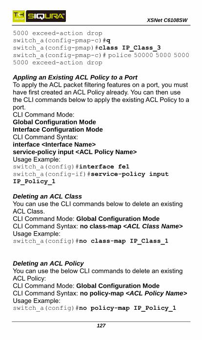
XSNet C6108SW
127
5000 exceed-action drop
switch_a(config-pmap-c)#q
switch_a(config-pmap)#class IP_Class_3
switch_a(config-pmap-c)# police 50000 5000 5000 5000 exceed-action drop
Appling an Existing ACL Policy to a Port To apply the ACL packet filtering features on a port, you must have first created an ACL Policy already. You can then use the CLI commands below to apply the existing ACL Policy to a port. CLI Command Mode: Global Configuration Mode Interface Configuration Mode CLI Command Syntax: interface <Interface Name> service-policy input <ACL Policy Name> Usage Example: switch_a(config)#interface fe1
switch_a(config-if)#service-policy input
IP_Policy_1
Deleting an ACL Class You can use the CLI commands below to delete an existing ACL Class. CLI Command Mode: Global Configuration Mode CLI Command Syntax: no class-map <ACL Class Name> Usage Example: switch_a(config)#no class-map IP_Class_1
Deleting an ACL Policy You can use the below CLI commands to delete an existing ACL Policy: CLI Command Mode: Global Configuration Mode CLI Command Syntax: no policy-map <ACL Policy Name> Usage Example: switch_a(config)#no policy-map IP_Policy_1

XSNet C6108SW
128
IP ACL
IP ACL Configuration The CLI commands for creation of Layer 3 Access Control Lists (standard and extended) are similar to those for ACLs created under QoS. However, QoS ACLs are implemented with the service-policy input CLI command, Layer 3 ACLs use the ip access-group command (described below).
Creating a Standard or Extended IP Access List To create a new Access List to allow or deny an IP address/range access to the switch, use the following CLI commands: CLI Command Mode: Global Configuration Mode CLI Command Syntax: (no) access-list (<100-199>|<2000-2699>) (deny|permit) (ip|gre|igmp|pim|rsvp|ospf|vrrp|ipcomp|any|<0-255>) (A.B.C.D/M|A.B.C.D A.B.C.D|host A.B.C.D|any) (A.B.C.D/M|A.B.C.D A.B.C.D|host A.B.C.D|any)
(no) access-list (<100-199>|<2000-2699>) (deny|permit) (udp) (A.B.C.D/M|A.B.C.D A.B.C.D|host A.B.C.D|any) ((eq|gt|lt|neq) <0-65535> | range <0-65535> <0-65535>|) (A.B.C.D/M|A.B.C.D A.B.C.D|host A.B.C.D|any) ((eq|gt|lt|neq) (tftp|bootp|<0-65535>) | range <0-65535> <0-65535>|)
(no) access-list (<100-199>|<2000-2699>) (deny|permit) (tcp) (A.B.C.D/M|A.B.C.D A.B.C.D|host A.B.C.D|any) ((eq|gt|lt|neq) <0-65535> | range <0-65535> <0-65535>|) (A.B.C.D/M|A.B.C.D A.B.C.D|host A.B.C.D|any) ((eq|gt|lt|neq) (ftp|ssh|telnet|www|<0-65535>) | range <0-65535> <0-65535>|) no access-list (<100-199>|<2000-2699>)

XSNet C6108SW
129
Usage Examples: switch_a(config)# access-list 2000 permit ip
host 5.5.5.5 host 3.3.3.3
switch_a(config)# access-list 2000 permit tcp
host 1.1.1.1 host 5.5.5.5 eq www
switch_a(config)# access-list 2000 permit udp
host 6.6.6.6 10.10.10.0 0.0.0.255 eq tftp
switch_a(config)# access-list 2000 permit gre
host 4.4.4.4 host 8.8.8.8
Applying a Defined Access List Once you have defined you standard or extended ACL, apply it to an interface using the ip access-group command: CLI Command Mode: Interface Configuration Mode CLI Command Syntax: ip access-group (<1-199>|<1300-2699>) (in) no ip access-group (<1-199>|<1300-2699>) (in) Usage Example: switch_a(config-if)#ip access-group 100 in
Show Access Lists You can view existing access lists with the show access-list command. CLI Command Mode: Privileged Exec Mode CLI Command Syntax: show access-list

XSNet C6108SW
130
SNMP
Enabling SNMP and configuring general settings To enable the SNMP feature of the switch, and configure its general settings (Description, Location, and Contact information), you must use the below CLI commands. CLI Command Mode: Global Configuration Mode CLI Command Syntax: snmp-server enable snmp-server description <1 -256 characters> snmp-server location <1 -256 characters> snmp-server contact <1 -256 characters> Usage Example: switch_a(config)# snmp-server enable
switch_a(config)# snmp-server description
Hub_Switch_1
switch_a(config)# snmp-server location
First_Floor_Closet
switch_a(config)# snmp-server contact
Administrator
Configuring SNMP Traps To configure the Trap features of the SNMP protocol on the switch, you use the following CLI commands: CLI Command Mode: Global Configuration Mode Interface Configuration Mode CLI Command Syntax: snmp-server trap-community 1 <1 -256 characters > snmp-server trap-community 2 <1 -256 characters > snmp-server trap-community 3 <1 -256 characters > snmp-server trap-community 4 <1 -256 characters > snmp-server trap-community 5 <1 -256 characters > snmp-server trap-ipaddress 1 <IP Address> snmp-server trap-ipaddress 2 <IP Address> snmp-server trap-ipaddress 3 <IP Address> snmp-server trap-ipaddress 4 <IP Address> snmp-server trap-ipaddress 5 <IP Address>

XSNet C6108SW
131
snmp-server trap-type enable linkDown snmp-server trap-type enable linkup snmp-server trap-type enable mac-notification snmp-server mac-notification interval <1 to 65535 seconds> snmp-server mac-notification history-size <1 to 500 entries> snmp-server trap mac-notification added snmp-server trap mac-notification removed Usage Example: switch_a(config)# snmp-server trap-community 1
Trap_Group_1
switch_a(config)# snmp-server trap-community 2
Trap_Group_2
switch_a(config)# snmp-server trap-community 3
Trap_Group_3
switch_a(config)# snmp-server trap-community 4
Trap_Group_4
switch_a(config)# snmp-server trap-community 5
Trap_Group_5
switch_a(config)# snmp-server trap-ipaddress 1
192.168.1.100
switch_a(config)# snmp-server trap-ipaddress 2
192.168.2.100
switch_a(config)# snmp-server trap-ipaddress 3
192.168.3.100
switch_a(config)# snmp-server trap-ipaddress 4
192.168.4.100
switch_a(config)# snmp-server trap-ipaddress 5
192.168.5.100
switch_a(config)# snmp-server trap-type enable
linkDown
switch_a(config)# snmp-server trap-type enable
linkup
switch_a(config)# snmp-server trap-type enable
mac-notification
switch_a(config)# snmp-server mac-notification
interval 60
switch_a(config)# snmp-server mac-notification

XSNet C6108SW
132
history-size 100
switch_a(config)#interface fe1
switch_a(config-if)#snmp-server trap
mac-notification added
switch_a(config-if)#snmp-server trap
mac-notification removed
Configuring SNMP v1 & v2 Community Groups To configure the SNMP v1 & v2 community groups to make the SNMP feature more secure, use the following CLI commands: CLI Command Mode: Global Configuration Mode CLI Command Syntax: snmp-server enable snmp-server community get <1 -256 characters> snmp-server community set <1 -256 characters> Usage Example: switch_a(config)# snmp-server community get
public
switch_a(config)# snmp-server community set
private
Adding SNMP v3 Users To add SNMP v3 Users to the switch and maximize the security for the SNMP feature, you must use the following CLI commands: CLI Command Mode: Global Configuration Mode CLI Command Syntax: snmp-server v3-user <username> <ro|rw> noauth snmp-server v3-user <username> <ro|rw> auth <md5|sha> <password> snmp-server v3-user <username> <ro|rw> priv <md5|sha> <password> des <pass_phrase>
Usage Example: switch_a(config)# snmp-server v3-user
SNMP_User_1 ro noauth
switch_a(config)# snmp-server v3-user
SNMP_User_2 ro auth md5 User2

XSNet C6108SW
133
switch_a(config)# snmp-server v3-user
SNMP_User_3 rw priv md5 User3 des Private_User
LLDP
Enable/Disable LLDP CLI Command Mode: Global Configuration Mode CLI Command Syntax: lldp enable no lldp enable
LLDP Holdtime Multiplier CLI Command Mode: Global Configuration Mode CLI Command Syntax: lldp holdtime multiplier <1-10> Usage Example: switch_a(config)#lldp holdtime multiplier 4
LLDP Transmit Interval CLI Command Mode: Global Configuration Mode CLI Command Syntax: lldp txinterval <5-32768> Usage Example: Set LLDP Transmit interval to 30 seconds switch_a(config)# lldp txinterval 30
Enable/Disable Global LLDP TLVs CLI Command Mode: Global Configuration Mode CLI Command Syntax: lldp tlv-global <TLV>
TLV Parameters
TLV Parameter Description
port-descr Port Description
sys-name System Name TLV
sys-descr System Description TLV
sys-cap System Capabilities
mgmt-addrs Management Address
port-vlan-id Port VLAN ID
mac-phy MAC/PHY Configuration/Status

XSNet C6108SW
134
port-and-protocol Port And Protocol VLAN ID
vlan-name VLAN Name
protocol-identity Protocol Identity
link-aggregation (Link Aggregation
max-frame Maximum Frame Size
Usage Example: switch_a(config)# lldp tlv-global mgmt-addrs
Enabling LLDP Transmit on a Port CLI Command Mode: Interface Configuration Mode CLI Command Syntax: lldp tx-pkt Example: switch_a(config)# lldp tx-pkt
Enabling LLDP Receive on a Port CLI Command Mode: Interface Configuration Mode CLI Command Syntax: lldp rcv-pkt Usage Example: switch_a# interface fe1
switch_a(config)# lldp rcv-pkt
Enabling LLDP Notify CLI Command Mode: Interface Configuration Mode CLI Command Syntax: lldp notification Enabling Transmission of the Management IP CLI Command Mode: Interface Configuration Mode CLI Command Syntax: lldp mgmt-ip vlan <vlan id> Usage Example: switch_a(config)# lldp mgmt-ip vlan 1
Enabling Specific TLV’s on a Port CLI Command Mode: Interface Configuration Mode CLI Command Syntax: lldp tlv-select <TLV ID> (see Error! eference source not found.) Usage Example:

XSNet C6108SW
135
switch_a(config)# lldp tlv-select mgmt-addrs
Routing
Create or Delete Static Route CLI Command Mode: Global Configuration Mode CLI Command Syntax: ip route <destination_network>/<prefix-length> <next-hop_address or exit interface> [<admin_distance>] no ip route <destination_network>/<prefix-length> <next-hop_address or exit interface> [<admin_distance>] Example: Set a route to remote network 172.16.3.0 with mask /24 where 192.168.2.4 is the next hop and administrative distance is 150. switch_a(config)# ip route 172.16.3.0/24
192.168.2.4 150
Show Existing IP Routes CLI Command Mode: Privileged Exec Mode CLI Command Syntax: show ip route example: switch_a#show ip route Codes: K - kernel, C - connected, S - static, R
- RIP
* - candidate default
S 1.111.111.0/24 [1/0] via 172.16.0.200, ge1
S 2.111.111.0/24 [1/0] via 172.16.0.200, ge1
C 127.0.0.0/8 is directly connected, lo
C 172.16.0.0/24 is directly connected, ge1
C 192.168.2.0/24 is directly connected, ge8
R 192.168.3.0/24 [120/2] via 172.16.0.200,
ge1, 00:03:33
R 192.168.4.0/24 [120/12] via 172.16.0.200,
ge1, 00:03:23
R 192.168.5.0/24 [120/12] via 172.16.0.200,

XSNet C6108SW
136
ge1, 00:03:23 Create or Delete Access List CLI Command Mode: Global Configuration Mode CLI Command Syntax: access-list <number> <permit or deny> <host_address> <mask> no access-list <number> <permit or deny> <host_address> <mask> Usage Example 1: Deny packets from host 172.16.30.2 switch_a(config)#access-list 10 deny host
172.16.30.2
Usage Example 2: Deny packets from hosts with IP address 172.16.30.x, where x = any number switch_a(config)#access-list 10 deny host
172.16.30.2 0.0.0.255
Configure Route Map CLI Command Mode: Global Configuration Mode, Route-Map Configuration Mode CLI Command Syntax: route-map name <permit or deny> <sequence_number> match ip address access_list <acl_id] Usage Example: switch_a(config)#route-map FIRST_MAP permit 12
switch_a(config-route-map)#match ip address 12
switch_a(config-route-map)#Set ip next-hop
10.1.2.1
Enable Proxy ARP CLI Command Mode: Interface Configuration Mode CLI Command syntax: ip proxy arp no ip proxy arp Usage Example: switch_a(config)#vlan database
switch_a(config-vlan)#int vlan1.1
switch_a(config-if)#ip proxy-arp

XSNet C6108SW
137
RIP
Enable or Disable RIP CLI Command Mode: Global Configuration Mode, Router Rip Config CLI Command Syntax: router rip Version 2 No router rip Usage Example: Enable RIP version 2 switch_a(config)# router rip
switch_a(config-router)#version 2
Enable RIP Routing on a Specific Network CLI Command Mode: Router Rip Config CLI Command Syntax: network <submask> Usage Example: Enable RIP on 2.2.2.0 255.255.255. 0 and 192.168.20.0 255.255.255.0 switch_a(config-router)#network 2.2.2.0/24
switch_a(config-router)#network
192.168.20.0/24
Show RIP Routing Table CLI Command Mode: Privileged Exec Mode CLI Command Syntax: show ip rip show ip interface brief Define RIP Neighbor CLI Command Mode: Router Rip Config CLI Command Syntax: neighbor <ip address> no neighbor <ip address> Set Interface to Passive CLI Command Mode: Router Rip Config

XSNet C6108SW
138
CLI Command Syntax: passive-interface <interface> no passive-interface <interface> RIP Default Metric CLI Command Mode: Router Rip Config CLI Command Syntax: default-metric <value> no default-metric RIP Send Version CLI Command Mode: Interface Configuration Mode CLI Command Syntax: ip rip send version <1,2> no ip rip send version <1,2> Redistribute CLI Command Mode: Router Rip Config CLI Command Syntax: redistribute (connected | static) [metric <0-16>] [route-map map_name] Usage Example: switch_a(config-router)# redistribute static metric 10
RIP Default Route CLI Command Mode: Router Rip Config CLI Command Syntax: default-information originate no default-information originate Define RIP Administrative Distance CLI Command Mode: Router Rip Config CLI Command Syntax: distance <admin-distance value> no distance Define RIP Timers CLI Command Mode: Router Rip Config

XSNet C6108SW
139
CLI Command Syntax: timers basic <update> <invalid> <flush> no timers basic Description of parameters:
Update: Rate (in seconds) at which updates are sent. Default is 30 seconds.
Invalid: Interval (in seconds) after which a route is declared invalid. The interval should be at least three times the value of update time. Default is 180 seconds.
Flush: Number of seconds that must pass before route is removed from routing table. Default is 240 seconds.
Usage Example: switch_a(config-router)# timers basic 30 180 120
RIP Authentication CLI Command Mode: Interface Configuration Mode CLI Command Syntax: ip rip authentication mode <md5 | text> Usage Example: switch_a(config-if)#ip rip authentication mode
md5
Other Protocols
GVRP Configuration CLI Command Mode: Global Configuration Mode CLI Command Syntax: set gvrp enable bridge 1 set gvrp disable bridge 1 Usage Examples: switch_a(config)# set gvrp enable bridge 1
switch_a(config)# set gvrp disable bridge 1
Dynamic VLAN creation in GVRP CLI Command Mode: Global Configuration Mode

XSNet C6108SW
140
CLI Command Syntax: set gvrp dynamic-vlan-creation disable bridge 1 Usage Example: switch_a(config)# set gvrp
dynamic-vlan-creation disable bridge 1
Enable or disable GVRP locally on a port CLI Command Mode: Global Configuration Mode CLI Command Syntax: set port gvrp enable <port id> set port gvrp disable <port id> Usage Examples: switch_a(config)# set port gvrp enable fe1
switch_a(config)# set port gvrp disable fe1
By default, when GVRP is enabled on a port the Applicant runs in Normal mode, which means that the GVRP protocol will not send out any PDUs from a port if the port is being blocked by STP. When you enable the GVRP Applicant to run in Active mode on a port, the GVRP protocol will continue to send PDUs from a port even if the port is being blocked by STP. The GVRP Applicant can be set to run in Normal or Active mode on a port by issuing the following CLI commands: CLI Command Mode: Global Configuration Mode CLI Command Syntax: set gvrp applicant state normal <port id> set gvrp applicant state active <port id> Usage Examples: switch_a(config)# set gvrp applicant state
normal fe1
switch_a(config)# set gvrp applicant state
active fe1
When you enable GVRP on a port, the Registrar is enabled on the port by default. You can enable or disable the GVRP Registrar on a port by issuing the following CLI commands: CLI Command Mode: Global Configuration Mode
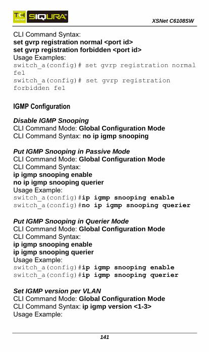
XSNet C6108SW
141
CLI Command Syntax: set gvrp registration normal <port id> set gvrp registration forbidden <port id> Usage Examples: switch_a(config)# set gvrp registration normal
fe1
switch_a(config)# set gvrp registration
forbidden fe1
IGMP Configuration
Disable IGMP Snooping CLI Command Mode: Global Configuration Mode CLI Command Syntax: no ip igmp snooping Put IGMP Snooping in Passive Mode CLI Command Mode: Global Configuration Mode CLI Command Syntax: ip igmp snooping enable no ip igmp snooping querier Usage Example: switch_a(config)#ip igmp snooping enable
switch_a(config)#no ip igmp snooping querier
Put IGMP Snooping in Querier Mode CLI Command Mode: Global Configuration Mode CLI Command Syntax: ip igmp snooping enable ip igmp snooping querier Usage Example: switch_a(config)#ip igmp snooping enable
switch_a(config)#ip igmp snooping querier
Set IGMP version per VLAN CLI Command Mode: Global Configuration Mode CLI Command Syntax: ip igmp version <1-3> Usage Example:

XSNet C6108SW
142
switch_a(config)#interface vlan1.1
switch_a(config-if)#ip igmp version 2
Enable/ disable IGMP fast-leave feature on a VLAN CLI Command Mode: VLAN Interface Configuration Mode CLI Command Syntax: ip igmp snooping fast-leave no ip igmp snooping fast-leave Usage Example - Enabling the IGMP fast-leave feature: switch_a(config)#interface vlan1.1
switch_a(config-if)#ip igmp snooping fast-leave
Usage Example - Disabling the IGMP fast-leave feature: switch_a(config)#interface vlan1.1
switch_a(config-if)#no ip igmp snooping
fast-leave
Enable/disable IGMP Report Suppression on a VLAN CLI Command Mode: VLAN Interface Configuration Mode CLI Command Syntax: ip igmp snooping report-suppression no ip igmp snooping report-suppression Usage Example - Enabling the IGMP Report Suppression feature: switch_a(config)#interface vlan1.1
switch_a(config-if)# ip igmp snooping
report-suppression
Configure IGMP query-interval and max-response-time CLI Command Mode: VLAN Interface Configuration Mode CLI Command Syntax: ip igmp query-interval <10-18000> ip igmp query-max-response-time <1-240> Usage Example - Configuring the IGMP query-interval parameter: switch_a(config-if)# ip igmp query-interval 125
Usage Example - Configuring the IGMP max-response-time parameter:
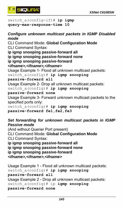
XSNet C6108SW
143
switch_a(config-if)# ip igmp
query-max-response-time 10
Configure unknown multicast packets in IGMP Disabled mode CLI Command Mode: Global Configuration Mode CLI Command Syntax: ip igmp snooping passive-forward all ip igmp snooping passive-forward none ip igmp snooping passive-forward <ifname>,<ifname>,<ifname> Usage Example 1- Flood all unknown multicast packets: switch_a(config)# ip igmp snooping
passive-forward all
Usage Example 2- Drop all unknown multicast packets: switch_a(config)# ip igmp snooping
passive-forward none
Usage Example 3- Forward unknown multicast packets to the specified ports only: switch_a(config)# ip igmp snooping
passive-forward fe1,fe2,fe3
Set forwarding for unknown multicast packets in IGMP Passive mode (And without Querier Port present) CLI Command Mode: Global Configuration Mode CLI Command Syntax: ip igmp snooping passive-forward all ip igmp snooping passive-forward none ip igmp snooping passive-forward <ifname>,<ifname>,<ifname> Usage Example 1 - Flood all unknown multicast packets: switch_a(config)# ip igmp snooping
passive-forward all
Usage Example 2 - Drop all unknown multicast packets: switch_a(config)# ip igmp snooping
passive-forward none

XSNet C6108SW
144
Usage Example 3 - Forward unknown multicast packets to the specified ports only: switch_a(config)# ip igmp snooping
passive-forward fe1,fe2,fe3
Set forwarding for unknown multicast packets in IGMP (with or without a Querier Port present) CLI Command Mode: Global Configuration Mode CLI Command Syntax: ip igmp snooping force-forward all ip igmp snooping force-forward none ip igmp snooping force-forward <ifname>,<ifname>,<ifname> Usage Example 1 - Flood all unknown multicast packets: switch_a(config)# ip igmp snooping
force-forward all
Usage Example 2 - Drop all unknown multicast packets: switch_a(config)# ip igmp snooping
force-forward none
Usage Example 3 - Forward unknown multicast packets to the specified ports only: switch_a(config)# ip igmp snooping
force-forward fe1,fe2,fe3
Set forwarding for unknown multicast packets in IGMP Querier mode CLI Command Mode: Global Configuration Mode CLI Command Syntax: ip igmp snooping force-forward all ip igmp snooping force-forward none ip igmp snooping force-forward <ifname>,<ifname>,<ifname> Usage Example 1 - Flood all unknown multicast packets: switch_a(config)# ip igmp snooping
force-forward all
Usage Example 2 - Drop all unknown multicast packets: switch_a(config)# ip igmp snooping
force-forward none

XSNet C6108SW
145
Usage Example 3 - Forward unknown multicast packets to the specified ports only: switch_a(config)# ip igmp snooping
force-forward fe1,fe2,fe3
Network Time Protocol (NTP)
Enable NTP CLI Command Mode: Global Configuration Mode CLI Command Syntax: ntp enable Set NTP Server CLI Command Mode: Global Configuration Mode CLI Command Syntax: ntp server <IP Address or Host Name of NTP Server> Example: switch_a(config)# ntp server 192.168.1.126
Set NTP Polling Interval CLI Command Mode: Global Configuration Mode CLI Command Syntax: ntp polling-interval <time in minutes, 1-10080> Example: switch_a(config)# ntp polling-interval 180
Set NTP Synchronization CLI Command Mode: Global Configuration Mode CLI Command Syntax: ntp sync-time
Set Current Time Zone CLI Command Mode: Global Configuration Mode CLI Command Syntax: clock timezone <Name of Time Zone> <UTC Offset in hh:mm format> Example: switch_a(config)# clock timezone CDT -6:00

XSNet C6108SW
146
Set Daylight Savings Time (Weekday Mode) CLI Command Mode: Global Configuration Mode CLI Command Syntax: clock summer-time <Name of Time Zone> weekday <start week number> <start day> <start month> <start hour> <start minute> <end week number> <end day> <end hour> <end minute> <time offset in minutes> Example: switch_a(config)#clock summer-time CDT weekday
2 Sun March 2 0 1 Sun November 2 0 60
Set Daylight Savings Time (Date Mode) CLI Command Mode: Global Configuration Mode CLI Command Syntax: clock summer-time <Name of Time Zone> date <start date> <start month> <start hour> <start minute> <end date> <end month> <end hour> <end minute> <time offset in minutes> Example: switch_a(config)#clock summer-time CDT date 9
March 2 0 2 November 2 0 60
GMRP
Enable/disable GMRP Globally CLI Command Mode: Global Configuration Mode CLI Command Syntax: set gmrp enable bridge 1 set gmrp disable bridge 1 Enable GMRP Locally on a Port CLI Command Mode: Global Configuration Mode CLI Command Syntax: set port gmrp enable <port id> set port gmrp enable <port id> When you enable GMRP on a port, the Registrar is in

XSNet C6108SW
147
Normal mode by default. Configure GMRP Registrar CLI Command Mode: Global Configuration Mode CLI Command Syntax: set gmrp registration normal <port id> set gmrp registration fixed fe1 <port id> set gmrp registration forbidden <port id> Enable/disable Forward All on a Port CLI Command Mode: Global Configuration Mode CLI Command Syntax: set gmrp fwdall enable <port id> set gmrp fwdall disable <port id>
DHCP
Set DHCP Server Parameters CLI Command Mode: Global Configuration Mode CLI Command Syntax: dhcp-server range <start IP> <end IP> dhcp-server subnet-mask <subnet mask in doted decimal notation> dhcp-server gateway <IP address> dhcp-server dns 1 <IP address> dhcp-server dns 2 <IP address> dhcp-server lease-time <0-864000> Example: switch_a(config)#dhcp-server range 192.168.7.100
192.168.7.107
switch_a(config)#dhcp-server subnet-mask
255.255.255.0
switch_a(config)#dhcp-server gateway 192.168.7.1
switch_a(config)#dhcp-server dns 1 1.2.3.4
switch_a(config)#dhcp-server dns 2 5.6.7.8
switch_a(config)#dhcp-server lease-time 86400
Enable/disable DHCP Server CLI Command Mode: Interface Configuration Mode

XSNet C6108SW
148
CLI Command Syntax: dhcp-server enable no dhcp-server enable Restart DHCP Server CLI Command Mode: Interface Configuration Mode CLI Command Syntax: dhcp-server restart Check IP Address Allocation CLI Command Mode: Privileged Exec Mode CLI Command Syntax: show dhcp-server binding
kvliet
Typewritten Text

XSNet C6108SW
149
Siqura B.V. Zuidelijk Halfrond 4 2801 DD Gouda The Netherlands Tel: +31-182-592-333 Fax: +31-182-592-123 www.siqura.com
Siqura has made a good faith effort to ensure the accuracy of the information in this document and disclaims the implied warranties of merchantability and fitness for a particular purpose and makes no express warranties, except as may be stated in its written agreement with and for its customers.
Siqura shall not be held liable to anyone for any indirect, special or consequential damages due to omissions or errors. The information and specifications in this document are subject to change without notice.
Copyright 2016. All Rights Reserved. All trademarks and registered trademarks are the property of their respective owners.
kvliet
Typewritten Text
kvliet
Typewritten Text
Note that XSNet Series manuals may cover multiple models. To establish if a particular feature or specification in this manual applies to the unit at hand, consult the datasheet of the given model.
kvliet
Typewritten Text
kvliet
Typewritten Text
Note: The EU Declaration of Conformity for this product can be found at www.siqura.com/support-files.