XNX Universal Transmitter - Gasdetectorsusa.com6 XNX Universal Transmitter Quick Start Guide 1...
72
Quick Start Guide XNX Universal Transmitter
Transcript of XNX Universal Transmitter - Gasdetectorsusa.com6 XNX Universal Transmitter Quick Start Guide 1...

Quick Start Guide
XNX Universal Transmitter


XNX Universal Transmitter Quick Start Guide 3
WARNINGSThe XNX Universal Transmitter is certified and designed for installation and »use worldwide in hazardous areas. Installation must be in accordance with the recognized standards of the »appropriate authority in the country concerned.Access to the interior of the detector, when carrying out any work, must only »be conducted by trained personnel.Before carrying out any work ensure local regulations and site procedures »are followed. Appropriate standards must be followed to maintain the overall certification of the detector.To reduce the risk of ignition of hazardous atmosphere, de-classify the area or »disconnect the equipment from the supply circuit before opening the detector enclosure. Keep assembly tightly closed during operation.Never open the XNX enclosure under power unless the area is known to be »non hazardous.The detector must be earthed/grounded for Intrinsic Safety, electrical safety »and to limit the effects of radio frequency interference. An earth/ground point is provided inside and outside the unit. The internal grounding shall be used as the primary equipment ground. The external terminal is only a supplemental bonding connection where local authorities permit or require such a connection.Take care when handling EC sensor cells as they may contain corrosive »solutions.Do not tamper or in any way disassemble the sensor cells. »Do not expose to temperatures outside the recommended range. »Do not expose sensor to organic solvents or flammable liquids. »At the end of their working life, sensors must be disposed of in an »environmentally safe manner. Disposal should be according to local waste management requirements and environmental legislation.Alternatively, sensors may be securely packaged and returned to Honeywell »Analytics clearly marked for environmental disposal.Electrochemical cells should NOT be incinerated as they may emit toxic fumes. »
HAzARdouS LocAtIoNS INStALLAtIoN RequIRemeNtS (uL/cSA)
To reduce the risk of ignition of hazardous atmospheres, conduit runs must »have a pour gland installed within 18 inches (457mm) of enclosure All ¾ inch NPT conduit, stopping plugs and adapters must be installed with 5 »¼ threads (minimum) engaged to Maintain Explosion Proof rating The XNX Cover Assembly must be fully seated to enclosure 9 threads »(minimum) to maintain Explosion Proof rating Stopping Plugs supplied (Honeywell Part Number 1226-0258) are approved »for use ONLY with the XNX Universal Transmitter. For units fitted with the Optional Relay Module: Relay Contact Ratings are »250 VAC 5A, 24 VDC 5A Resistive Loads Only Terminal block screws should be tightened to 4.5 Lb/in maximum »Reference XNX Control Drawing 1226E0402 for additional information »regarding IS function (Local HART and EC Personality).
XNX Universal Transmitter Quick Start Guide4
1 Mounting and Location of Detectors ������������������������������������������������61�1 Mounting the XNX Universal Transmitter �������������������������������6
2 Wiring the XNX ������������������������������������������������������������������������������������92�1 General Wiring Considerations �����������������������������������������������9
2.2 Distance Considerations for Installation ............................102�3 POD Connections �������������������������������������������������������������������132�4 4-20mA Output, Common Connections and Power����������������132�5 Terminal Block Connections �������������������������������������������������152�6 EC Personality Wiring ������������������������������������������������������������16
2.6.1 XNX Electrochemical (EC) Sensor Installation ..............182�7 mV Personality Wiring �����������������������������������������������������������202�8 IR Personality Wiring �������������������������������������������������������������24
2.8.1 Connecting a Searchpoint Optima Plus or Searchline Excel ..............................................................................252.8.2 Connecting Generic mA Device .....................................25
3 Options ����������������������������������������������������������������������������������������������293�1 Local HART® Handheld ����������������������������������������������������������293�2 Relays ��������������������������������������������������������������������������������������303�3 Modbus® ����������������������������������������������������������������������������������������������������������������������������������������������� 31
4 Powering the XNX for the First Time �����������������������������������������������324�1 XNX Units Configured for EC, mV, and IR (except Searchline Excel) ��������������������������������������������������������������������������������������������324�2 XNX IR Units Configured for Searchline Excel ��������������������334�3 Configuring the XNX Universal Transmitter �������������������������34
5 The XNX Front Panel ������������������������������������������������������������������������355�1 Controls and Navigation ��������������������������������������������������������355�2 The General Status Screen ����������������������������������������������������355�3 Entering the Menu Structure �������������������������������������������������37
6 Gas Calibration Menu ����������������������������������������������������������������������386�1 Calibration ������������������������������������������������������������������������������38
6.1.1 Calibration Procedure ....................................................386.1.2 Zero and Span Calibration for XNX EC Sensors ...........416.1.3 Zero and Span Calibration of XNX EC Hydrogen Sulfide (H2S) Sensors ........................................................................................... 416.1.4 XNX EC Sensor Operational Life ...................................426.1.5 Zero and Span Calibration for MPD Sensors ............................426.1.6 Cross Calibration procedure for MPD-CB1 ....................446.1.7 Calibrating the 705/705HT .............................................466.1.8 Calibrating the Sensepoint/Sensepoint HT ....................466.1.9 Calibrating the Searchline Excel and Searchpoint Optima Plus ................................................................................46
6�2 Functional Gas Testing (Bump Test) �������������������������������������467 XNX Electrochemical Sensor Data �������������������������������������������������47
Table of Contents
XNX Universal Transmitter Quick Start Guide 5
Table of Contents (cont’d)
8 XNX Catalytic Bead and IR Replacement Sensor Cartridges �������489 Warning Messages ���������������������������������������������������������������������������4810 Fault Messages �������������������������������������������������������������������������������5211 Informational Messages ����������������������������������������������������������������62

XNX Universal Transmitter Quick Start Guide6
1 Mounting and Location of Detectors
cAutIoNThe location of the transmitters and sensors should be made in accordance with any relevant local and national legislation, standards or codes of practice. Always replace detectors with a detector of the same type. The detector should be mounted where the gas is most likely to be present. The following points should be noted when locating gas detectors.
When locating detectors consider the possible damage caused by natural •events e.g. rain or flooding.
Consider ease of access for functional testing and servicing.•
Consider how escaping gas may behave due to natural or forced air •currents.
NoteThe placement of detectors should be determined following the advice of experts having specialist knowledge of gas dispersion, experts having knowledge of the process plant system and equipment involved, safety and engineering personnel. The agreement reached on the location of detectors should be recorded.
1�1 Mounting the XNX Universal Transmitter
The XNX Universal Transmitter can be mounted in a number of different methods using the integral mounting tabs.
Using the mounting tabs, the XNX can be attached to:
flat wall surface•
Unistrut• ®
With the optional Pipe Mount kit, the XNX can be mounted to pipe of diameter 2 to 6 in (50 to 150mm).
A ceiling mount bracket kit (1226A0358) is also available.Integral Mounting Lugs
Figure 1. Integral Mounting Lugs and Optional Pipe and Ceiling Mounts
XNX Universal Transmitter Quick Start Guide 7
1.67"42.41 mm
5.6"124.24 mm
6.00"15.4 mm
7.75"196.85 mm
4.48"113.8 mm
0.625"15.88mm
2.054"52.18mm
0.945"24mm
1.2"31.75mm
1.768"44.90 mm
3.176"80.67 mm
1.768"44.90 mm
0.55"14.35 mm
6.138"158.75mm
Allow 11" 280mmfor Maint./Service
4"101.6mm
6"15
2 m
mw
/sun
shi
eld
XNX withSearchpoint Optima Plus
Allow12"
305mmFor
MaintenanceService
XNX with MPD or Local EC Sensor
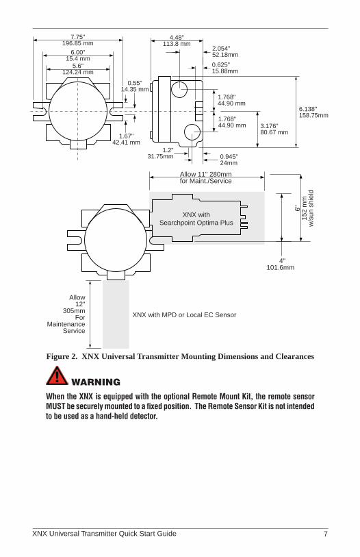
Figure 2. XNX Universal Transmitter Mounting Dimensions and Clearances
WARNINGWhen the XNX is equipped with the optional Remote Mount Kit, the remote sensor MUST be securely mounted to a fixed position. The Remote Sensor Kit is not intended to be used as a hand-held detector.

XNX Universal Transmitter Quick Start Guide8
The XNX is configured with 5 cable/conduit entries built into the housing for wiring and mounting sensors; Figure 3 provides the guidelines to proper installation of the XNX.
NoteWhile relay wiring can use any available cable/conduit entry in the XNX enclosure, do not use the same cable/conduit entry for both relay reset and relay signal lines to avoid electrical noise.
Option Position
Local HART® Option B
MPD, 705 Series, Sensepoint Series C
Catalytic Bead Sensor C
Searchpoint Optima Plus A or E
Searchline Excel Typically C
Remote Sensor Connection (except EC ) Any remaining
Searchpoint Optima Plus - Remote Any remaining
Modbus® Any remaining
Relays Any remaining
Power Any remaining
A
E
D
B
C
*
* Limited access due to IS barrier if equipped with electrochemical cell.
Figure 3. XNX Universal Transmitter Cable/Conduit Entry AssignmentsIntegral Mounting Lugs
Figure 4. Integral Mounting Lugs and Optional Pipe and Ceiling Mounts
XNX Universal Transmitter Quick Start Guide 9
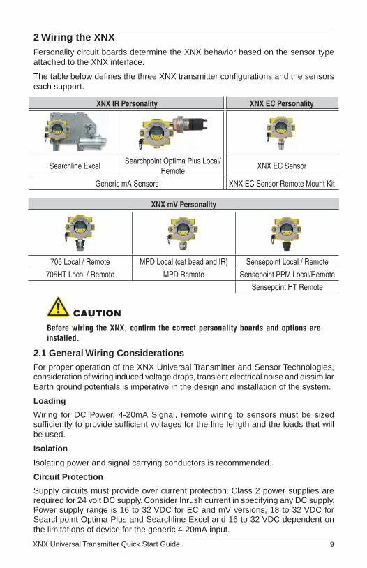
2 Wiring the XNXPersonality circuit boards determine the XNX behavior based on the sensor type attached to the XNX interface.
The table below defines the three XNX transmitter configurations and the sensors each support.
XNX IR Personality XNX EC Personality
Searchline ExcelSearchpoint Optima Plus Local/
RemoteXNX EC Sensor
Generic mA Sensors XNX EC Sensor Remote Mount Kit
XNX mV Personality
705 Local / Remote MPD Local (cat bead and IR) Sensepoint Local / Remote
705HT Local / Remote MPD Remote Sensepoint PPM Local/Remote
Sensepoint HT Remote
cAutIoNBefore wiring the XNX, confirm the correct personality boards and options are installed.
2�1 General Wiring ConsiderationsFor proper operation of the XNX Universal Transmitter and Sensor Technologies, consideration of wiring induced voltage drops, transient electrical noise and dissimilar Earth ground potentials is imperative in the design and installation of the system.
Loading
Wiring for DC Power, 4-20mA Signal, remote wiring to sensors must be sized sufficiently to provide sufficient voltages for the line length and the loads that will be used.
Isolation
Isolating power and signal carrying conductors is recommended.
Circuit Protection
Supply circuits must provide over current protection. Class 2 power supplies are required for 24 volt DC supply. Consider Inrush current in specifying any DC supply. Power supply range is 16 to 32 VDC for EC and mV versions, 18 to 32 VDC for Searchpoint Optima Plus and Searchline Excel and 16 to 32 VDC dependent on the limitations of device for the generic 4-20mA input.
XNX Universal Transmitter Quick Start Guide10
Loads
The use of High Inrush or Inductive loads may affect the performance of the XNX. For best reliability use resistive loads only.
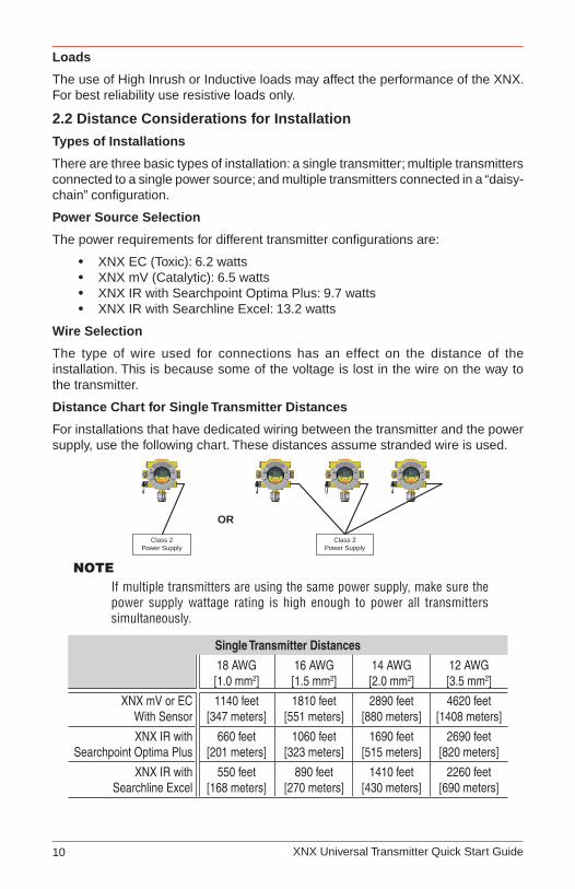
2�2 Distance Considerations for Installation
Types of Installations
There are three basic types of installation: a single transmitter; multiple transmitters connected to a single power source; and multiple transmitters connected in a “daisy-chain” configuration.
Power Source Selection
The power requirements for different transmitter configurations are:
XNX EC (Toxic): 6.2 watts•XNX mV (Catalytic): 6.5 watts•XNX IR with Searchpoint Optima Plus: 9.7 watts•XNX IR with Searchline Excel: 13.2 watts•
Wire Selection
The type of wire used for connections has an effect on the distance of the installation. This is because some of the voltage is lost in the wire on the way to the transmitter.
Distance Chart for Single Transmitter Distances
For installations that have dedicated wiring between the transmitter and the power supply, use the following chart. These distances assume stranded wire is used.
Class 2Power Supply
Class 2Power Supply
OR
NoteIf multiple transmitters are using the same power supply, make sure the power supply wattage rating is high enough to power all transmitters simultaneously.
Single Transmitter Distances
18 AWG[1.0 mm2]
16 AWG[1.5 mm2]
14 AWG[2.0 mm2]
12 AWG[3.5 mm2]
XNX mV or ECWith Sensor
1140 feet[347 meters]
1810 feet[551 meters]
2890 feet[880 meters]
4620 feet[1408 meters]
XNX IR withSearchpoint Optima Plus
660 feet[201 meters]
1060 feet[323 meters]
1690 feet[515 meters]
2690 feet[820 meters]
XNX IR withSearchline Excel
550 feet[168 meters]
890 feet[270 meters]
1410 feet[430 meters]
2260 feet[690 meters]
XNX Universal Transmitter Quick Start Guide 11
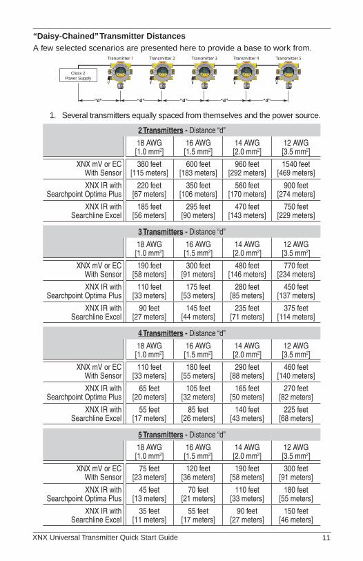
“Daisy-Chained” Transmitter DistancesA few selected scenarios are presented here to provide a base to work from.
Class 2Power Supply
“d”“d”“d”“d”“d”
Transmitter 1 Transmitter 2 Transmitter 3 Transmitter 4 Transmitter 5
Several transmitters equally spaced from themselves and the power source.1.
2 Transmitters - Distance “d”
18 AWG[1.0 mm2]
16 AWG[1.5 mm2]
14 AWG[2.0 mm2]
12 AWG[3.5 mm2]
XNX mV or ECWith Sensor
380 feet[115 meters]
600 feet[183 meters]
960 feet[292 meters]
1540 feet[469 meters]
XNX IR withSearchpoint Optima Plus
220 feet[67 meters]
350 feet[106 meters]
560 feet[170 meters]
900 feet[274 meters]
XNX IR withSearchline Excel
185 feet[56 meters]
295 feet[90 meters]
470 feet[143 meters]
750 feet[229 meters]
3 Transmitters - Distance “d”
18 AWG[1.0 mm2]
16 AWG[1.5 mm2]
14 AWG[2.0 mm2]
12 AWG[3.5 mm2]
XNX mV or ECWith Sensor
190 feet[58 meters]
300 feet[91 meters]
480 feet[146 meters]
770 feet[234 meters]
XNX IR withSearchpoint Optima Plus
110 feet[33 meters]
175 feet[53 meters]
280 feet[85 meters]
450 feet[137 meters]
XNX IR withSearchline Excel
90 feet[27 meters]
145 feet[44 meters]
235 feet[71 meters]
375 feet[114 meters]
4 Transmitters - Distance “d”
18 AWG[1.0 mm2]
16 AWG[1.5 mm2]
14 AWG[2.0 mm2]
12 AWG[3.5 mm2]
XNX mV or ECWith Sensor
110 feet[33 meters]
180 feet[55 meters]
290 feet[88 meters]
460 feet[140 meters]
XNX IR withSearchpoint Optima Plus
65 feet[20 meters]
105 feet[32 meters]
165 feet[50 meters]
270 feet[82 meters]
XNX IR withSearchline Excel
55 feet[17 meters]
85 feet[26 meters]
140 feet[43 meters]
225 feet[68 meters]
5 Transmitters - Distance “d”
18 AWG[1.0 mm2]
16 AWG[1.5 mm2]
14 AWG[2.0 mm2]
12 AWG[3.5 mm2]
XNX mV or ECWith Sensor
75 feet[23 meters]
120 feet[36 meters]
190 feet[58 meters]
300 feet[91 meters]
XNX IR withSearchpoint Optima Plus
45 feet[13 meters]
70 feet[21 meters]
110 feet[33 meters]
180 feet[55 meters]
XNX IR withSearchline Excel
35 feet[11 meters]
55 feet[17 meters]
90 feet[27 meters]
150 feet[46 meters]
XNX Universal Transmitter Quick Start Guide12
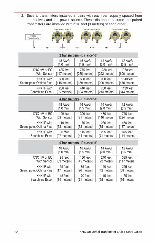
Several transmitters installed in pairs with each pair equally spaced from 2. themselves and the power source. These distances assume the paired transmitters are installed within 10 feet [3 meters] of each other.
Class 2Power Supply
“d”“d”“d”
Transmitters 1 and 2 Transmitters 3 and 4 Transmitters 5 and 6
2 Transmitters - Distance “d”
18 AWG[1.0 mm2]
16 AWG[1.5 mm2]
14 AWG[2.0 mm2]
12 AWG[3.5 mm2]
XNX mV or ECWith Sensor
485 feet[147 meters]
775 feet[235 meters]
1230 feet[292 meters]
1970 feet[600 meters]
XNX IR withSearchpoint Optima Plus
380 feet[115 meters]
600 feet[180 meters]
960 feet[290 meters]
1540 feet[470 meters]
XNX IR withSearchline Excel
280 feet[85 meters]
440 feet[134 meters]
700 feet[213 meters]
1130 feet[344 meters]
4 Transmitters - Distance “d”
18 AWG[1.0 mm2]
16 AWG[1.5 mm2]
14 AWG[2.0 mm2]
12 AWG[3.5 mm2]
XNX mV or ECWith Sensor
190 feet[58 meters]
300 feet[91 meters]
480 feet[146 meters]
770 feet[234 meters]
XNX IR withSearchpoint Optima Plus
110 feet[33 meters]
175 feet[53 meters]
280 feet[85 meters]
450 feet[137 meters]
XNX IR withSearchline Excel
90 feet[27 meters]
145 feet[44 meters]
235 feet[71 meters]
375 feet[114 meters]
6 Transmitters - Distance “d”
18 AWG[1.0 mm2]
16 AWG[1.5 mm2]
14 AWG[2.0 mm2]
12 AWG[3.5 mm2]
XNX mV or ECWith Sensor
95 feet[33 meters]
150 feet[45 meters]
240 feet[73 meters]
385 feet[117 meters]
XNX IR withSearchpoint Optima Plus
55 feet[17 meters]
85 feet[26 meters]
140 feet[42 meters]
225 feet[68 meters]
XNX IR withSearchline Excel
45 feet[14 meters]
70 feet[21 meters]
115 feet[35 meters]
185 feet[56 meters]
XNX Universal Transmitter Quick Start Guide 13
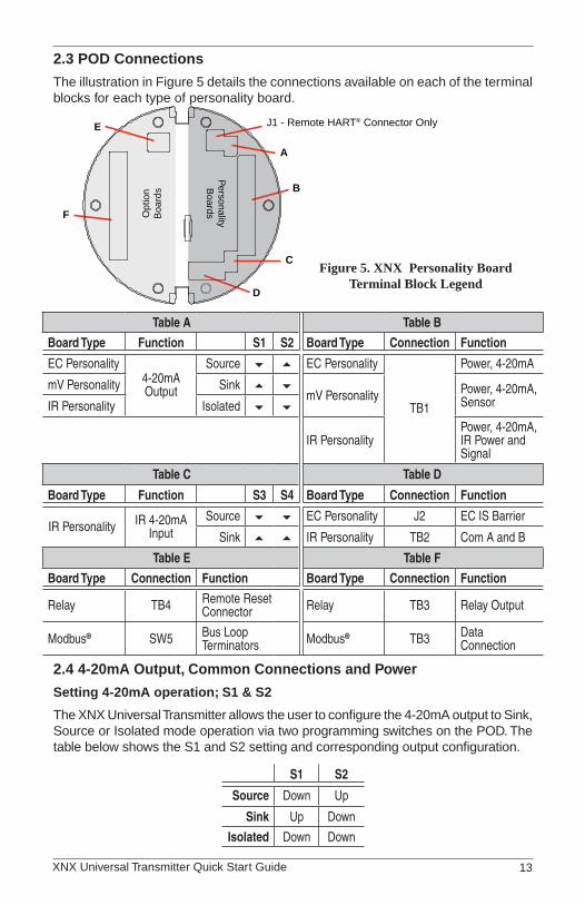
2�3 POD Connections
The illustration in Figure 5 details the connections available on each of the terminal blocks for each type of personality board.
J1 - Remote HART® Connector Only
PersonalityB
oardsOpt
ion
Boa
rds
A
B
C
D
E
F
Figure 5. XNX Personality Board Terminal Block Legend
Table A Table B
Board Type Function S1 S2 Board Type Connection Function
EC Personality4-20mA Output
Source EC Personality
TB1
Power, 4-20mA
mV Personality Sink mV Personality Power, 4-20mA,
SensorIR Personality Isolated
IR PersonalityPower, 4-20mA, IR Power and Signal
Table C Table D
Board Type Function S3 S4 Board Type Connection Function
IR Personality IR 4-20mA Input
Source EC Personality J2 EC IS Barrier
Sink IR Personality TB2 Com A and B
Table E Table F
Board Type Connection Function Board Type Connection Function
Relay TB4 Remote Reset Connector Relay TB3 Relay Output
Modbus® SW5 Bus Loop Terminators Modbus® TB3 Data
Connection
2�4 4-20mA Output, Common Connections and Power
Setting 4-20mA operation; S1 & S2
The XNX Universal Transmitter allows the user to configure the 4-20mA output to Sink, Source or Isolated mode operation via two programming switches on the POD. The table below shows the S1 and S2 setting and corresponding output configuration.
S1 S2
Source Down Up
Sink Up Down
Isolated Down Down
XNX Universal Transmitter Quick Start Guide14
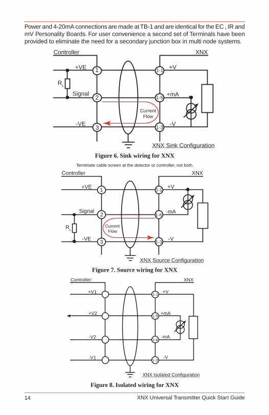
Power and 4-20mA connections are made at TB-1 and are identical for the EC , IR and mV Personality Boards. For user convenience a second set of Terminals have been provided to eliminate the need for a secondary junction box in multi node systems.
Controller
+VE
Signal
-VE
RL
1
2
3
1-1
1-5
1-3
+V
+mA
-V
XNX
XNX Sink Configuration
CurrentFlow
Figure 6. Sink wiring for XNX
XNX Source Configuration
Controller
+VE
Signal
-VE
RL
1
2
3
1-1
1-6
1-3
+V
-mA
-V
XNX
CurrentFlow
Terminate cable screen at the detector or controller, not both.
Figure 7. Source wiring for XNXController
+V1
+V2
-V2
1-1
1-5
1-6
+V
+mA
-V
XNX
1-3
-mA
-V1
XNX Isolated Configuration
Figure 8. Isolated wiring for XNX
XNX Universal Transmitter Quick Start Guide 15
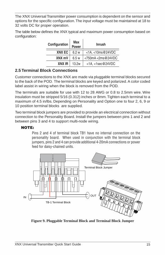
The XNX Universal Transmitter power consumption is dependent on the sensor and options for the specific configuration. The input voltage must be maintained at 18 to 32 volts DC for proper operation.
The table below defines the XNX typical and maximum power consumption based on configuration:
ConfigurationMax
PowerInrush
XNX EC 6.2 w <1A, <10ms@24VDC
XNX mV 6.5 w <750mA <2ms@24VDC
XNX IR 13.2w <1A, <1sec@24VDC
2�5 Terminal Block Connections
Customer connections to the XNX are made via pluggable terminal blocks secured to the back of the POD. The terminal blocks are keyed and polarized. A color coded label assist in wiring when the block is removed from the POD.
The terminals are suitable for use with 12 to 28 AWG or 0.8 to 2.5mm wire. Wire insulation must be stripped 5/16 (0.312) inches or 8mm. Tighten each terminal to a maximum of 4.5 in/lbs. Depending on Personality and Option one to four 2, 6, 9 or 10 position terminal blocks are supplied.
Two terminal block jumpers are provided to provide an electrical connection without connection to the Personality Board. Install the jumpers between pins 1 and 2 and between pins 3 and 4 to support multi-node wiring.
Note:Pins 2 and 4 of terminal block TB1 have no internal connection on the personality board. When used in conjunction with the terminal block jumpers, pins 2 and 4 can provide additional 4-20mA connections or power feed for daisy-chained units.
TB-1 Terminal Block
Terminal Block Jumper
INOUT
Figure 9. Pluggable Terminal Block and Terminal Block Jumper
XNX Universal Transmitter Quick Start Guide16
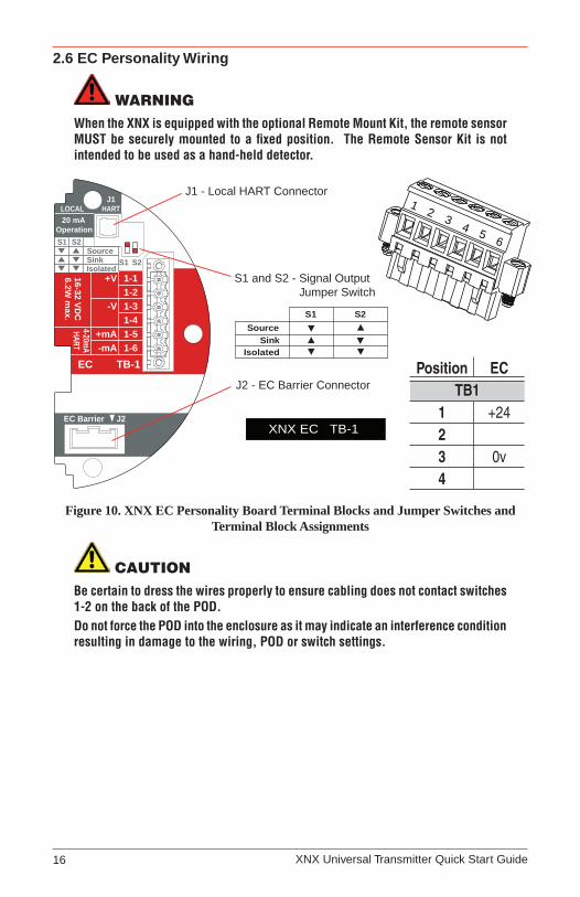
2�6 EC Personality Wiring
WARNINGWhen the XNX is equipped with the optional Remote Mount Kit, the remote sensor MUST be securely mounted to a fixed position. The Remote Sensor Kit is not intended to be used as a hand-held detector.
Position ECTB1
1 +2423 0v4
J1 - Local HART Connector
S1 and S2 - Signal Output Jumper Switch
▼▼
▲S2S1
Isolated
▼Sink ▼▲
Source
XNX EC TB-1
J2 - EC Barrier Connector
HART20 mA
Operation
LOCALJ1
S1
S1SourceSinkIsolated
S2
S2
EC Barrier J2
+V 1-1
EC TB-1
4-20mAHART
16-32 VDC
6.2W m
ax.
1-2-V 1-3
1-4+mA 1-5-mA 1-6
12
34 5
6
Figure 10. XNX EC Personality Board Terminal Blocks and Jumper Switches and Terminal Block Assignments
cAutIoNBe certain to dress the wires properly to ensure cabling does not contact switches 1-2 on the back of the POD. Do not force the POD into the enclosure as it may indicate an interference condition resulting in damage to the wiring, POD or switch settings.

XNX Universal Transmitter Quick Start Guide 17
�
ECAdaptor
Optional Local HARTIS Barrier mustbe connected to J1
EC IS Barrier mustbe connected to J2
4
3
2
1
-
+
6
5
J1 HART
S1 S2
J2 EC Barrier
Term
inal
Blo
ck 1
Local HARTIS Barrier(optional)
HARTAdaptor
EC IS Barrier
Sensor Cartridge
Weatherproof Cap
Sensor Retainer
Sensor Cartridge
Weatherproof Cap
Sensor Retainer
Local Sensor Mounted to Transmitter
Sensor Mounted toRemote Sensor Kit
Figure 11. EC Personality WiringNote:
Reference Control Drawing 3000E3157 for install requirements on EC cells and remote mounting.

XNX Universal Transmitter Quick Start Guide18
2�6�1 XNX Electrochemical (EC) Sensor Installation
cAutIoNFor biased sensors (e.g. Nitrogen Dioxide) remove the sensor stabilizer from the bottom of the sensor prior to installation.
Using Figure 12 as a guide, follow the procedure below:
Check that the label on the new sensor is the correct gas type.1.
Unscrew the weatherproof cover, loosen the retainer locking screw with the 2. supplied hex key and unscrew the sensor retainer.
Plug in the new sensor taking care to align the sensor pins with the 3. connector.
Refit the sensor retainer, tighten the locking screw with the supplied hex 4. key and refit the weatherproof cover.
Countdown time of up to 180 seconds (dependent on sensor type) is 5. displayed.
Acknowledgement of the gas type will be required before proceeding. For 6. more information on setting gas type, see Gas Selection.
After the sensor is installed and the gas type is confirmed, the Range, alarm 7. levels and other important settings must be set; see Section 4.1 - Configuring the XNX Universal Transmitter.
Once the XNX has been configured, calibrate the detector following the 8. procedures in Section 6.1 - Calibration.
Transmitter
Sensor Retainer &Locking Screw
2
1
3
4
5
New Sensor
Weatherproof Cap
Figure 12. Installing Plug In Sensor

XNX Universal Transmitter Quick Start Guide 19
XNX EC Sensor Remote Mounting Kit
The remote sensor mounting kit is used to remotely mount the sensor from the transmitter. To remotely mount the sensor, follow the procedure below.
Unscrew the weatherproof cover, loosen the retainer locking screw and 1. unscrew the sensor retainer.
Remove the sensor by pulling without twisting.2.
Plug the remote sensor cable connector into the bottom of the transmitter.3.
Route the cable to the location where the remote sensor is to be mounted.4.
If necessary, cut the cable to the required length.5.
cAutIoNTake care not to cut the cable too short. Once cut, additional lengths of cable cannot be added as this will invalidate the intrinsically safe certification. We also recommend that a loop of cable is made at the junction box to allow slack for any future re-termination.The enclosure of the remotely mounted sensor contains aluminum. Care must be taken to avoid ignition hazards due to impact or friction when installed in the Zone 1 location.All cable entry devices and blanking elements shall be certified in type of explosion protection flameproof enclosure “Ex e”, suitable for the conditions of use and correctly installed.
Mount the remote sensor junction box ensuring enough room below to fit 6. the sensor and weatherproof cover.
Attach the cable to the remote terminal box via the gland provided.7.
Make the wiring connections as shown below.8.
Fit the terminal box lid.9.
Plug the sensor into the socket at the bottom of the terminal box.10.
Fit the sensor retainer, tighten the locking screw and fit the weatherproof cover.11.
Calibrate the detector following the procedure12. s in Section 6.1 - Calibration.

XNX Universal Transmitter Quick Start Guide20
ConnectionsPin # Color
1 Yellow2 Green3 Blue4 White5 Red6 Black
Sensor Cartridge
Weatherproof Cap
Sensor Retainer
Sensor Mounted toRemote Sensor Kit
CAUTION
Take care not to cut the cable too short. Once cut, additional lengths of cablecannot be added as this will invalidate the intrinsically safe certification. HAalso recommends that a loop of cable is made at the junction box to allowslack for any future re-termination.
The enclosure of the remotely mounted sensor contains aluminum. Care mustbe taken to avoid ignition hazards due to impact or friction when installed in theZone 1 location.
All cable entry devices and blanking elements shall be certified in type ofexplosion protection flameproof enclosure “Ex e”, suitable for the conditions ofuse and correctly installed.
Figure 13. Installing Remote Sensor Mounting Kit
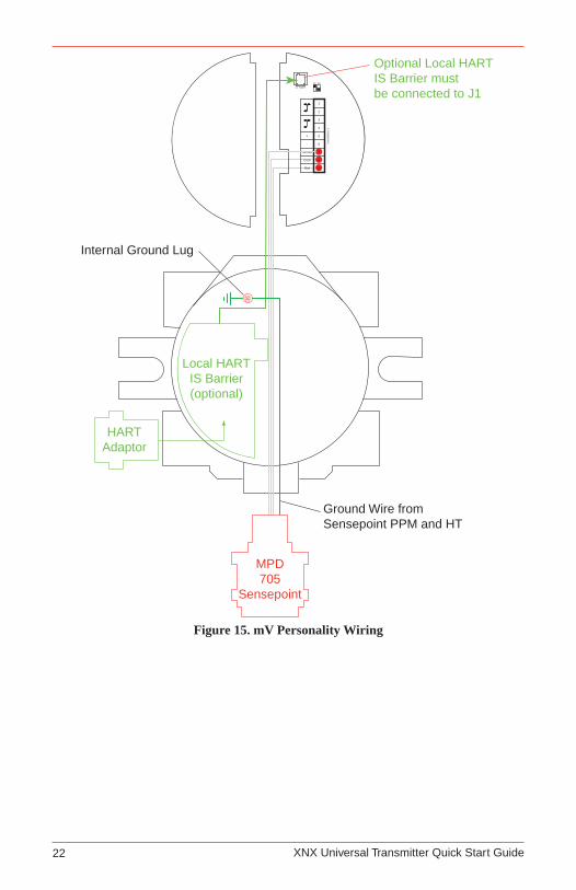
2�7 mV Personality WiringXNX Universal Transmitter with the mV personality Board allows interface to a number of HA’s Multi Purpose Detector MPD and field proven 705 and Sensepoint devices.
cAutIoNCheck to ensure the XNX and mV Sensor has the appropriate approvals for your • installation prior to commissioning
Check the mV Sensor you are installing has compatible threads - 3/4 NPT or M25.•
Connections from the mV Sensor to the XNX are made via a single pluggable terminal block allowing ease of installation and service. HA recommends an 8” (203mm)service length for wiring be maintained. The Wire Colors for the connections for each sensor type are shown in Figure 14.Be sure wires for 4-20mA outputs are routed away from sources of noise such as relay wires.
XNX Universal Transmitter Quick Start Guide 21
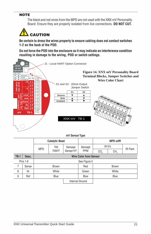
NoteThe black and red wires from the MPD are not used with the XNX mV Personality Board. Ensure they are properly isolated from live connections. DO NOT CUT.
cAutIoNBe certain to dress the wires properly to ensure cabling does not contact switches 1-2 on the back of the POD.
Do not force the POD into the enclosure as it may indicate an interference condition resulting in damage to the wiring, POD or switch settings.
Figure 14. XNX mV Personality Board Terminal Blocks, Jumper Switches and
Wire Color Chart
HART20 mA
Operation
LOCALJ1
S1
+V 1-1
mV TB-1
MPD, 705Sensepoint
4-20mAHART
16-32 VDC
6.5W m
ax.
1-2-V 1-3
1-4+mA 1-5-mA 1-6
Sense 1-70v 1-8
Ref 1-9
S1SourceSinkIsolated
S2
S2
XNX mV TB-1
▼▼
S2S1
▼▼Isolated
▲Sink ▼
Source
J1 - Local HART Option Connector
S1 and S2 - 20mA Output Jumper Switch
▼▲
12
34
5 67
89
mV Sensor Type
Catalytic Bead MPD w/IR
MPD705
705HTSensept
Senspt HTSensept
PPMIR 5%
IR Flam CO2 CH4
TB-1 Desc. Wire Color from Sensor
Pins 1-6 See Figure 5
7 Sense Brown Red Brown
8 0v White Green White
9 Ref Blue Blue Blue
Internal Ground
XNX Universal Transmitter Quick Start Guide22
Local HARTIS Barrier(optional)
HARTAdaptor
4
3
2
1
Ref
+
9
8
7
6
5
J1 HART
S1 S2
Term
inal
Blo
ck 1
Com
Sense
-
Optional Local HARTIS Barrier mustbe connected to J1
Ground Wire from Sensepoint PPM and HT
Internal Ground Lug
MPD705
Sensepoint
Figure 15. mV Personality Wiring

XNX Universal Transmitter Quick Start Guide 23
mV Remote Sensor Mounting
The sensor can be mounted remotely from the transmitter. To remotely mount the sensor, follow the procedure below.
Unscrew the XNX’s weatherproof cover, loosen the retainer locking screw 1. with the supplied hex key.
Run conduit from one of the XNX’s available conduit entries to the location 2. of the remote terminal housing.
A Terminal Housing provides a mounting base for the sensor and contains the associated electronic circuit. The installation wiring enters the Terminal Housing via conduit.
Killark HKB-BC Box00704-A-1755
Adalet X1HFC3L Box00704-A-1756
Honeywell Analytics Box00780-A-0100
Figure 16. Remote Terminal HousingsThe distance between the XNX Transmitter and remote installation must comply with the following to insure proper operation. Distances are dependent on sensor types and the wire gauge used.
AWG Metric Wire GaugeMPD CB1, 705
Series.Sensepoint Series Sensors
MPD IC1, IV1 & IF1 Sensors
24 0.25 mm2 12m (47 ft.) 30m (97 ft.)
22 20m (65 ft.) 50m (162 ft.)
20 0.5 mm2 30m (97 ft.) 80m (260 ft.)
18 50m (162 ft.) 120m (390 ft.)*
16 1.0 mm2 80m (260 ft.)* 200m (650 ft.)*
* Frequency of Zero calibration may increase due to the changes in wire resistance from changing temperature
Wire the pluggable terminal block as shown in Figure 14 then plug the 3. connector into the back of the mV personality board.Mount the remote sensor junction box ensuring enough room below to fit 4. the sensor and weatherproof cover.Attach the conduit to the remote terminal box.5. In the remote junction box, connect the wires from the XNX to the 3-way 6. terminal block provided in the terminal enclosure.Note
The black and red wires from the MPD are not used with the XNX mV Personality Board. Ensure they are properly isolated from live connections. DO NOT CUT.

XNX Universal Transmitter Quick Start Guide24
cAutIoNThe enclosure of the remotely mounted 705 HT sensor contains aluminum. Care must be taken to avoid ignition hazards due to impact or friction when installed in the Zone 1 location.All cable entry devices and blanking elements shall be certified in type of explosion protection flameproof enclosure “Ex d” or “Ex e”, suitable for the conditions of use and correctly installed
Attach and wire the sensor into the terminal box.7.
Fit the terminal box lid.8.
Fit the sensor retainer, tighten the locking screw and fit the weatherproof 9. cover (if required).
Calibrate the detector following the procedure is Section 3 - Calibration.10.
2�8 IR Personality Wiring
Gas concentrations are read by the XNX from the Searchpoint Optima Plus or Searchline Excel 4-20mA output. A digital communication connection on TB2 provides an additional confirmation as well as diagnostic information.
Connections from the Searchpoint Optima Plus or Searchline Excel to the XNX are made via two pluggable terminal blocks allowing ease of installation and service see Figure 14. HA recommends an 8” (203mm) service length for wiring be maintained.
Be sure wires for 4-20mA outputs are routed away from sources of noise such as relay wires The Searchpoint Optima Plus or Searchline Excel can be supplied in either Sink or Source mode operation and is typically labeled on the white wire exiting the Searchpoint Optima Plus or Searchline Excel. Use the table below to set S3 and S4 to the complimentary operating state of the equipment.
For more information see the Searchpoint Optima Plus Operating Instructions (2104M0508) or the Searchline Excel Technical Manual (2104M0506).
cAutIoNBe certain to dress the wires properly to ensure cabling does not contact switches 1-4 on the back of the POD.
Do not force the POD into the enclosure as it may indicate an interference condition resulting in damage to the wiring, POD or switch settings.
WARNINGSetting of S3 and S4 while power is applied or improperly set prior to applying power WILL PERMANENTLY DAMAGE the XNX. Both switches must be set in either Source or Sink prior to applying power.Do not adjust switch settings while power is applied to the XNX; permanent damage WILL occur.
XNX Universal Transmitter Quick Start Guide 25
2�8�1 Connecting a Searchpoint Optima Plus or Searchline ExcelConnections from the Searchpoint Optima Plus or Searchline Excel to the XNX are made via two pluggable terminal blocks allowing ease of installation and service (see Figure 14). HA recommends an 8” service length for wiring be maintained.
The Searchpoint Optima Plus or Searchline Excel can be supplied in either Sink or Source mode operation and is typically labeled on the white wire exiting the Searchpoint Optima Plus or Searchline Excel. Use the table in Figure 14 to set S3 and S4 to the SAME output type that appears on the wire tag of the IR device.
Note:A second, black-handled screwdriver is included for use on terminal blocks 2 and 4. This tool is smaller than the magnetic wand and is designed to fit into the terminal connections on TB2 and TB4.
For more information see the Searchpoint Optima Plus Operating Instructions (2104M0508) or the Searchline Excel Technical Manual (2104M0506).
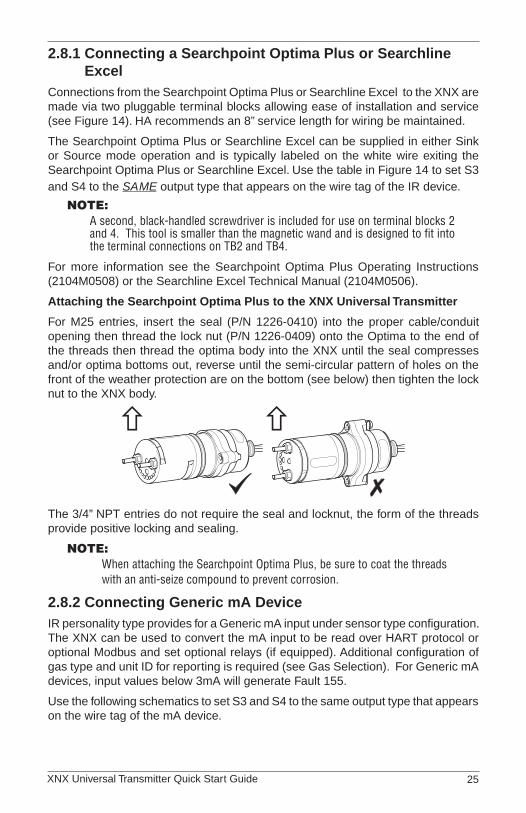
Attaching the Searchpoint Optima Plus to the XNX Universal Transmitter
For M25 entries, insert the seal (P/N 1226-0410) into the proper cable/conduit opening then thread the lock nut (P/N 1226-0409) onto the Optima to the end of the threads then thread the optima body into the XNX until the seal compresses and/or optima bottoms out, reverse until the semi-circular pattern of holes on the front of the weather protection are on the bottom (see below) then tighten the lock nut to the XNX body.
The 3/4” NPT entries do not require the seal and locknut, the form of the threads provide positive locking and sealing.
Note:When attaching the Searchpoint Optima Plus, be sure to coat the threads with an anti-seize compound to prevent corrosion.
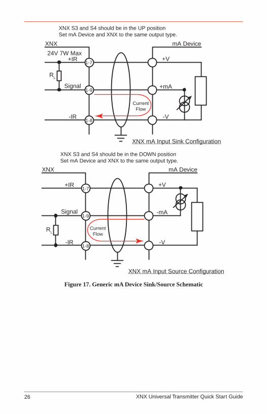
2�8�2 Connecting Generic mA DeviceIR personality type provides for a Generic mA input under sensor type configuration. The XNX can be used to convert the mA input to be read over HART protocol or optional Modbus and set optional relays (if equipped). Additional configuration of gas type and unit ID for reporting is required (see Gas Selection). For Generic mA devices, input values below 3mA will generate Fault 155.
Use the following schematics to set S3 and S4 to the same output type that appears on the wire tag of the mA device.
XNX Universal Transmitter Quick Start Guide26
XNX
+IR
Signal
-IR
RL
1-7
1-9
1-8
+V
+mA
-V
mA Device
XNX mA Input Sink Configuration
CurrentFlow
24V 7W Max
XNX S3 and S4 should be in the UP positionSet mA Device and XNX to the same output type.
XNX mA Input Source Configuration
XNX
+IR
Signal
-IR
RL
1-7
1-9
1-8
+V
-mA
-V
mA Device
CurrentFlow
XNX S3 and S4 should be in the DOWN positionSet mA Device and XNX to the same output type.
Figure 17. Generic mA Device Sink/Source Schematic

XNX Universal Transmitter Quick Start Guide 27
HART20 mA
Operation
LOCALJ1
S1
+V 1-1
SearchlineSearchpoint
4-20mAHART
18-32 VDC
13.2W m
ax.
1-2-V 1-3
1-4+mA 1-5-mA 1-6
1-7- Ir+ Ir
1-8Sig 1-9
S1SourceSinkIsolated
S2
S2
Ir TB-1TB-2 Ir Data
S3Source
Sink
S4
▼▼
▲▼▼▲
S2S1
IsolatedSink
Source
J1 - Local HART Connector
S1 and S2 - 20mA Output Jumper Switch
S3 and S4 - IR 20mA InputJumper Switch
XNX IR TB-1
▼▲
▼▲
S4S3
SinkSource
TB2
Desc. From Searchpoint Optima Plus
Searchline Excel
1 Com B Orange
2 Com A Blue
TB1
Desc. From Searchpoint Optima Plus
Searchline Excel
1 24v
See Common ConnectionsSection 2.2.3
2
3 Gnd
4
5 20mA +
6 20mA -
7 24v Red
8 0v Black
9 Sig White
XNX
Desc. From Searchpoint Optima Plus
Searchline Excel
Earth Green/Yellow
12
34
5 67
89
TB1
12
TB2
Figure 18. XNX IR Personality Board Terminal Blocks, Jumper Switches and Wiring Guide
Searchline Excel and Searchpoint Optima Plus Remote Installation
Junction Boxes are available for the Searchline Excel and Searchpoint Optima Plus to facilitate remote mounting from the XNX Universal Transmitter. Junction boxes are available for installations requiring UL/CSA or ATEX approvals. Consult the Searchline Excel Technical Handbook (2104M0506) or Searchpoint Optima Plus Operating Instructions (2104M0508) for specifics on remote installations or contact your Honeywell Analytics representative for more information.
XNX Universal Transmitter Quick Start Guide28
��
Local HARTIS Barrier(optional)
HARTAdaptor
Optional Local HARTIS Barrier must beconnected to J1
SearchpointOptima Plus
4
3
2
1
Sig
Gnd
+24
+
9
8
7
6
5
J1 HARTS1 S2
Term
inal
Blo
ck 1
B
A
2
1
Terminal Block 2IR Data
S3 S4
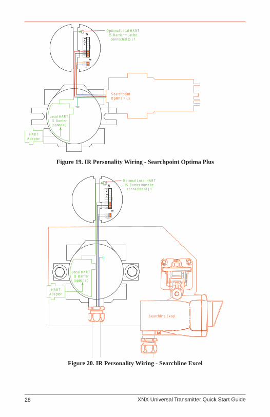
Figure 19. IR Personality Wiring - Searchpoint Optima Plus��
Local HARTIS Barrier(optional)
Optional Local HARTIS Barrier must beconnected to J1
4
3
2
1
Sig
Gnd
+24
+
9
7
6
5
J1 HARTS1 S2
Term
inal
Blo
ck 1
B
A 1
2
Terminal Block 2IR Data
S3 S4
8
HARTAdaptor
Searchline Excel
Figure 20. IR Personality Wiring - Searchline Excel
XNX Universal Transmitter Quick Start Guide 29
3 Options
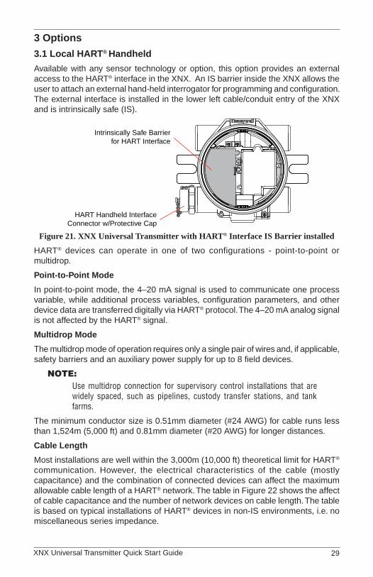
3�1 Local HART® Handheld
Available with any sensor technology or option, this option provides an external access to the HART® interface in the XNX. An IS barrier inside the XNX allows the user to attach an external hand-held interrogator for programming and configuration. The external interface is installed in the lower left cable/conduit entry of the XNX and is intrinsically safe (IS).
Intrinsically Safe Barrierfor HART Interface
HART Handheld InterfaceConnector w/Protective Cap
Figure 21. XNX Universal Transmitter with HART® Interface IS Barrier installed
HART® devices can operate in one of two configurations - point-to-point or multidrop.
Point-to-Point Mode
In point-to-point mode, the 4–20 mA signal is used to communicate one process variable, while additional process variables, configuration parameters, and other device data are transferred digitally via HART® protocol. The 4–20 mA analog signal is not affected by the HART® signal.
Multidrop Mode
The multidrop mode of operation requires only a single pair of wires and, if applicable, safety barriers and an auxiliary power supply for up to 8 field devices.
Note:Use multidrop connection for supervisory control installations that are widely spaced, such as pipelines, custody transfer stations, and tank farms.
The minimum conductor size is 0.51mm diameter (#24 AWG) for cable runs less than 1,524m (5,000 ft) and 0.81mm diameter (#20 AWG) for longer distances.
Cable Length
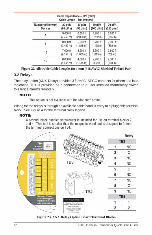
Most installations are well within the 3,000m (10,000 ft) theoretical limit for HART® communication. However, the electrical characteristics of the cable (mostly capacitance) and the combination of connected devices can affect the maximum allowable cable length of a HART® network. The table in Figure 22 shows the affect of cable capacitance and the number of network devices on cable length. The table is based on typical installations of HART® devices in non-IS environments, i.e. no miscellaneous series impedance.
XNX Universal Transmitter Quick Start Guide30
Cable Capacitance – pf/ft (pf/m)Cable Length – feet (meters)
Number of Network Devices
20 pf/ft (65 pf/m)
30 pf/ft (95 pf/m)
50 pf/ft (160 pf/m)
70 pf/ft (225 pf/m)
1 9,000 ft(2,769 m)
6,500 ft(2,000 m)
4,200 ft(1,292 m)
3,200 ft(985 m)
5 8,000 ft(2,462 m)
5,900 ft(1,815 m)
3,700 ft(1,138 m)
2,900 ft(892 m)
10 7,000 ft(2,154 m)
5,200 ft(1,600 m)
3,300 ft(1,015 m)
2,500 ft 769 m)
15 6,000 ft(1,846 m)
4,600 ft(1,415 m)
2,900 ft(892 m)
2,300 ft(708 m)
Figure 22. Allowable Cable Lengths for 1 mm (#18 AWG) Shielded Twisted Pair
3�2 Relays
The relay option (XNX-Relay) provides 3 form “C” SPCO contacts for alarm and fault indication. TB4 is provided as a connection to a user installed momentary switch to silence alarms remotely.
Note:This option is not available with the Modbus® option.
Wiring for the relays is through an available cable/conduit entry to a pluggable terminal block. See Figure 4 for the terminal block legend.
Note:A second, black-handled screwdriver is included for use on terminal blocks 2 and 4. This tool is smaller than the magnetic wand and is designed to fit into the terminal connections on TB4.
Warning: Powerexternally supplied.Disconnect at sourceprior to servicing.
3-53-43-33-23-1
3-63-73-83-9
CNC
TB4Remote
Reset SWRelay Ratings250VAC 5A24VDC 5A
NOC
NC
NONCC
NO Faul
tLe
vel 2
Leve
l 1
TB-3 RELAY
TB3 Relay Connections
Warning: Power externallysupplied, disconnect at source
prior to servicing
Relay Contact Ratings:250 VAC 5 amps24 VDC 5 amps
RelayTB3
1 NC2 C3 NO4 NC5 C6 NO7 NC8 C9 NO
TB41 12 2
12
34
56
78
9
TB3
12
TB4
Figure 23. XNX Relay Option Board Terminal Blocks
XNX Universal Transmitter Quick Start Guide 31
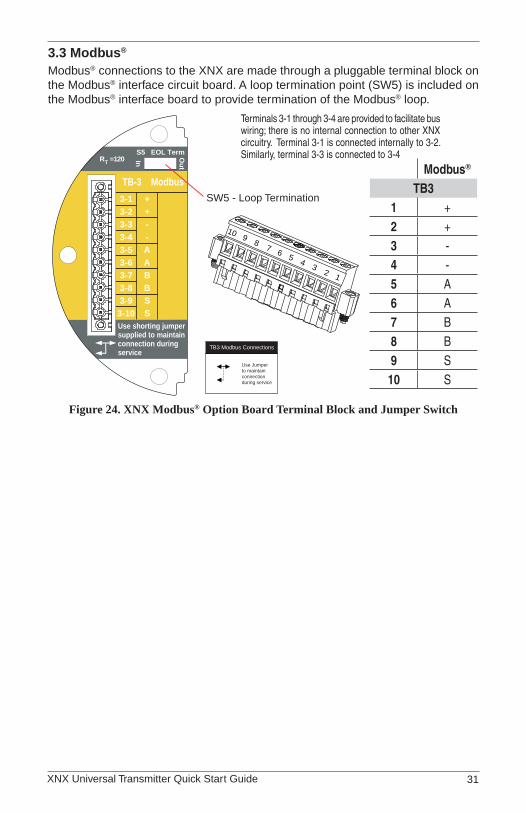
3�3 Modbus®
Modbus® connections to the XNX are made through a pluggable terminal block on the Modbus® interface circuit board. A loop termination point (SW5) is included on the Modbus® interface board to provide termination of the Modbus® loop.
Terminals 3-1 through 3-4 are provided to facilitate bus wiring; there is no internal connection to other XNX circuitry. Terminal 3-1 is connected internally to 3-2. Similarly, terminal 3-3 is connected to 3-4
3-53-43-33-23-1
3-63-73-83-9
3-10
A--++
ABBS
TB-3 Modbus
SUse shorting jumpersupplied to maintainconnection duringservice
S5 EOL TermOut
InRT =120
TB3 Modbus Connections
Use Jumperto maintainconnectionduring service
SW5 - Loop Termination
Modbus®
TB31 +2 +3 -4 -5 A6 A7 B8 B9 S10 S
123
45
678
910
Figure 24. XNX Modbus® Option Board Terminal Block and Jumper Switch

XNX Universal Transmitter Quick Start Guide32
4 Powering the XNX for the First Time4�1 XNX Units Configured for EC, mV, and IR (except Searchline Excel)
After mounting and wiring the XNX, the plug in sensor should be fitted (if equipped) and the installation visually and electrically tested as below.
WARNINGPrior to carrying out any work, ensure local and site procedures are followed. Ensure that the associated control panel is inhibited so as to prevent false alarms. Minimum and maximum controller alarm levels should not be set at less than 10% or greater than 90% of the full scale range of the detector. CSA and FM agency limits are 60% LEL or 0.6mg/m3.
cAutIoNThe following procedure should be followed carefully and only performed by suitably trained personnel
Check that the transmitter is wired correctly according to this manual and 1. the associated control equipment manual.
If equipped, unscrew the weatherproof cover, loosen the sensor retainer 2. locking screw and unscrew the retainer.
Plug in the sensor cartridge taking care to align the sensor pins with the 3. connector holes in the PCB.
cAutIoNFor toxic sensors, remove the shorting clip from the bottom of the sensor prior to installation. For O2 sensor, there is no shorting clip provided.
Refit the sensor retainer, tighten the locking screw and refit the weatherproof 4. cover.
Note:Before replacing the cover on the transmitter housing, coat the threads with anti-seize compound to prevent corrosion buildup.
Also inspect the cover o-ring for cracking or any other defect that might compromise the integrity of the seal. If it is damaged, replace with the o-ring supplied in the accessory kit.
Apply power to the XNX which will in turn provide power to the detector.5.
The detector output will be forced to 3mA (default fault/inhibit).6.
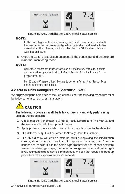
The XNX display will enter a start up routine displaying the initialization 7. screen, then the transmitter loads its operating system, data from the sensor and checks if it is the same type transmitter and sensor software version numbers, gas type, the detection range and span calibration gas level, estimated time to next calibration due, and self test result. The boot-up procedure takes approximately 45 seconds.
XNX Universal Transmitter Quick Start Guide 33
Figure 25. XNX Initialization and General Status Screens
Note:In the final stages of boot-up, warnings and faults may be observed until the user performs the proper configuration, calibration, and reset activities described in the following sections. See Section 10 for descriptions of warnings and faults.
Once the General Status screen appears, the transmitter and detector are 8. in normal ‘monitoring’ mode.
Note:Calibration of sensors attached to the XNX is mandatory before the detector can be used for gas monitoring. Refer to Section 6.1 - Calibration for the proper procedure.
For EC and mV personalities, be sure to perform Accept New Sensor Type before calibrating the sensor.
4�2 XNX IR Units Configured for Searchline Excel
When powering the XNX fitted to the Searchline Excel, the following procedure must be followed to assure proper installation.
cAutIoNThe following procedure should be followed carefully and only performed by suitably trained personnel
Check that the transmitter is wired correctly according to this manual and 1. the associated control equipment manual.
Apply power to the XNX which will in turn provide power to the detector.2.
The detector output will be forced to 3mA (default fault/inhibit).3.
The XNX display will enter a start up routine displaying the initialization 4. screen, then the transmitter loads its operating system, data from the sensor and checks if it is the same type transmitter and sensor software version numbers, gas type, the detection range and span calibration gas level, estimated time to next calibration due, and self test result. The boot-up procedure takes approximately 45 seconds.
Figure 26. XNX Initialization and General Status Screens
XNX Universal Transmitter Quick Start Guide34
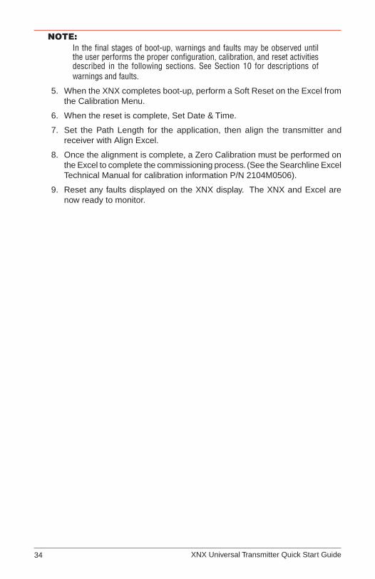
Note:In the final stages of boot-up, warnings and faults may be observed until the user performs the proper configuration, calibration, and reset activities described in the following sections. See Section 10 for descriptions of warnings and faults.
When the XNX completes boot-up, perform a Soft Reset on the Excel from 5. the Calibration Menu.
When the reset is complete, Set Date & Time.6.
Set the Path Length for the application, then align the transmitter and 7. receiver with Align Excel.
Once the alignment is complete, a Zero Calibration must be performed on 8. the Excel to complete the commissioning process. (See the Searchline Excel Technical Manual for calibration information P/N 2104M0506).
Reset any faults displayed on the XNX display. The XNX and Excel are 9. now ready to monitor.
XNX Universal Transmitter Quick Start Guide 35
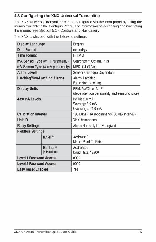
4�3 Configuring the XNX Universal Transmitter
The XNX Universal Transmitter can be configured via the front panel by using the menus available in the Configure Menu. For information on accessing and navigating the menus, see Section 5.1 - Controls and Navigation.
The XNX is shipped with the following settings:
Display Language EnglishDate Format mm/dd/yyTime Format HH:MMmA Sensor Type (w/IR Personality) Searchpoint Optima PlusmV Sensor Type (w/mV personality) MPD-IC1 (%Vol)Alarm Levels Sensor Cartridge DependentLatching/Non-Latching Alarms Alarm: Latching
Fault: Non-LatchingDisplay Units PPM, %VOL or %LEL
(dependent on personality and sensor choice)4-20 mA Levels Inhibit: 2.0 mA
Warning: 3.0 mAOverrange: 21.0 mA
Calibration Interval 180 Days (HA recommends 30 day interval)Unit ID XNX #nnnnnnnnRelay Settings Alarm Normally De-EnergizedFieldbus Settings
HART® Address: 0Mode: Point-To-Point
Modbus®
(if installed)Address: 5Baud Rate: 19200
Level 1 Password Access 0000Level 2 Password Access 0000Easy Reset Enabled Yes
XNX Universal Transmitter Quick Start Guide36
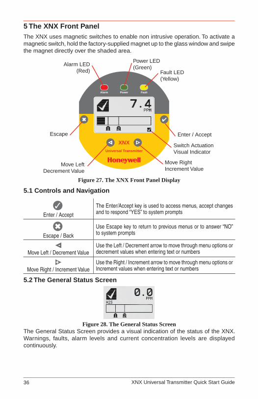
5 The XNX Front PanelThe XNX uses magnetic switches to enable non intrusive operation. To activate a magnetic switch, hold the factory-supplied magnet up to the glass window and swipe the magnet directly over the shaded area.
XNXUniversal Transmitter
- +
Power FaultAlarm
Alarm LED(Red) Fault LED
(Yellow)
Power LED(Green)
Escape
Move LeftDecrement Value
Move RightIncrement Value
Enter / Accept
Switch ActuationVisual Indicator
Figure 27. The XNX Front Panel Display
5�1 Controls and Navigation
✓Enter / Accept
The Enter/Accept key is used to access menus, accept changes and to respond “YES” to system prompts
✖Escape / Back
Use Escape key to return to previous menus or to answer “NO” to system prompts
Move Left / Decrement ValueUse the Left / Decrement arrow to move through menu options or decrement values when entering text or numbers
Move Right / Increment ValueUse the Right / Increment arrow to move through menu options or Increment values when entering text or numbers
5�2 The General Status Screen
Figure 28. The General Status ScreenThe General Status Screen provides a visual indication of the status of the XNX. Warnings, faults, alarm levels and current concentration levels are displayed continuously.
XNX Universal Transmitter Quick Start Guide 37
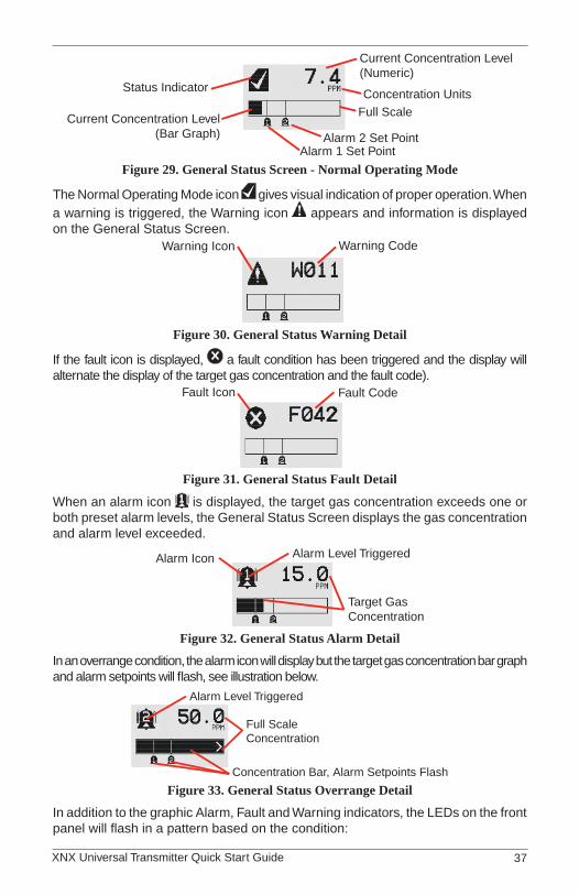
Status Indicator
Current Concentration Level(Numeric)
Alarm 2 Set PointAlarm 1 Set Point
Current Concentration Level(Bar Graph)
Full ScaleConcentration Units
Figure 29. General Status Screen - Normal Operating Mode
The Normal Operating Mode icon gives visual indication of proper operation. When a warning is triggered, the Warning icon appears and information is displayed on the General Status Screen.
Warning CodeWarning Icon
Figure 30. General Status Warning Detail
If the fault icon is displayed, a fault condition has been triggered and the display will alternate the display of the target gas concentration and the fault code).
Fault CodeFault Icon
Figure 31. General Status Fault Detail
When an alarm icon is displayed, the target gas concentration exceeds one or both preset alarm levels, the General Status Screen displays the gas concentration and alarm level exceeded.
Target GasConcentration
Alarm Icon Alarm Level Triggered
Figure 32. General Status Alarm Detail
In an overrange condition, the alarm icon will display but the target gas concentration bar graph and alarm setpoints will flash, see illustration below.
Full ScaleConcentration
Alarm Level Triggered
Concentration Bar, Alarm Setpoints Flash
Figure 33. General Status Overrange Detail
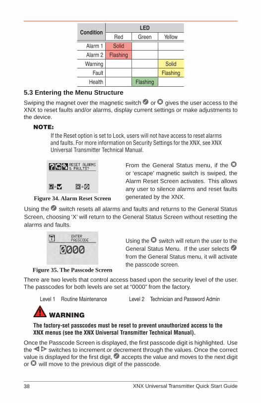
In addition to the graphic Alarm, Fault and Warning indicators, the LEDs on the front panel will flash in a pattern based on the condition:
XNX Universal Transmitter Quick Start Guide38
ConditionLED
Red Green Yellow
Alarm 1 Solid
Alarm 2 Flashing
Warning Solid
Fault Flashing
Health Flashing
5�3 Entering the Menu Structure
Swiping the magnet over the magnetic switch ✓ or ✖ gives the user access to the XNX to reset faults and/or alarms, display current settings or make adjustments to the device.
Note:If the Reset option is set to Lock, users will not have access to reset alarms and faults. For more information on Security Settings for the XNX, see XNX Universal Transmitter Technical Manual.
Figure 34. Alarm Reset Screen
From the General Status menu, if the ✖ or ‘escape’ magnetic switch is swiped, the Alarm Reset Screen activates. This allows any user to silence alarms and reset faults generated by the XNX.
Using the ✓ switch resets all alarms and faults and returns to the General Status Screen, choosing ‘X’ will return to the General Status Screen without resetting the alarms and faults.
Figure 35. The Passcode Screen
Using the ✖ switch will return the user to the General Status Menu. If the user selects ✓
from the General Status menu, it will activate the passcode screen.
There are two levels that control access based upon the security level of the user. The passcodes for both levels are set at “0000” from the factory.
Level 1 Routine Maintenance Level 2 Technician and Password Admin
WARNINGThe factory-set passcodes must be reset to prevent unauthorized access to the XNX menus (see the XNX Universal Transmitter Technical Manual).
Once the Passcode Screen is displayed, the first passcode digit is highlighted. Use the switches to increment or decrement through the values. Once the correct value is displayed for the first digit, ✓ accepts the value and moves to the next digit or ✖ will move to the previous digit of the passcode.
XNX Universal Transmitter Quick Start Guide 39
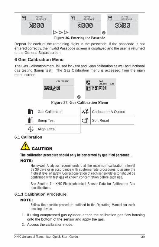
✓ Figure 36. Entering the Passcode
Repeat for each of the remaining digits in the passcode. If the passcode is not entered correctly, the Invalid Passcode screen is displayed and the user is returned to the General Status screen.
6 Gas Calibration MenuThe Gas Calibration menu is used for Zero and Span calibration as well as functional gas testing (bump test). The Gas Calibration menu is accessed from the main menu screen.
✓ Figure 37. Gas Calibration Menu
Gas Calibration Calibrate mA Output
Bump Test Soft Reset
Align Excel
6�1 Calibration
cAutIoNThe calibration procedure should only be performed by qualified personnel.
Note:Honeywell Analytics recommends that the maximum calibration interval be 30 days or in accordance with customer site procedures to assure the highest level of safety. Correct operation of each sensor/detector should be confirmed with test gas of known concentration before each use.
See Section 7 - XNX Electrochemical Sensor Data for Calibration Gas specifications.
6�1�1 Calibration ProcedureNote:
Follow the specific procedure outlined in the Operating Manual for each sensing device.
If using compressed gas cylinder, attach the calibration gas flow housing 1. onto the bottom of the sensor and apply the gas.
Access the calibration mode. 2.

XNX Universal Transmitter Quick Start Guide40
Figure 38. Gas Calibration MenuNote:
The Gas Calibration menu is for both Zero and Span Calibration.
Zero Calibration
Sensor Readingat Current Settings
Figure 39. Zero Calibration Screen
Figure 40. Zero Calibration in Progress
Select ✓ then apply the zero gas and as the sensor detects the gas and the concentration is increasing, the values displayed will reflect the changing concentration. Selecting ✖ will return to the Gas Calibration menu.
If the Zero Calibration is successful, the XNX Universal Transmitter will 3. display the Zero Passed screen.
Figure 41. Zero Calibration Passed
Span Calibration
Note:If a Span Calibration is not required, select the ✖ to skip the Span Calibration and return to the Calibration menu.
When the Zero Calibration is complete or it is skipped, the Span 4. Concentration screen appears to indicate the concentration value of the gas used for calibration.
Figure 42. Span Gas Concentration ScreenSelect 5. ✓ to choose the first digit and use the switches to increment or decrement the values; ✓ accepts the new value and move to the next digit. Continue until all 3 digits have been selected.
XNX Universal Transmitter Quick Start Guide 41
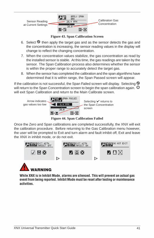
Sensor Readingat Current Settings
Calibration GasConcentration
Figure 43. Span Calibration Screen
Select 6. ✓ then apply the target gas and as the sensor detects the gas and the concentration is increasing, the sensor reading values in the display will change to reflect the changing concentration.
When the concentration values stabilize, the gas concentration as read by 7. the installed sensor is stable. At this time, the gas readings are taken by the sensor. The Span Calibration process also determines whether the sensor is within the proper range to accurately detect the target gas.
When the sensor has completed the calibration and the span algorithms have 8. determined that it is within range, the Span Passed screen will appear.
If the calibration is not successful, the Span Failed screen will display. Selecting ✓ will return to the Span Concentration screen to begin the span calibration again. ✖ will exit Span Calibration and return to the Main Calibrate screen.
Arrow indicatesgas values too low
Selecting ‘✔’ returns tothe Span Concentrationscreen
Figure 44. Span Calibration Failed
Once the Zero and Span calibrations are completed successfully, the XNX will exit the calibration procedure. Before returning to the Gas Calibration menu however, the user will be prompted to Exit and turn alarm and fault inhibit off, Exit and leave the XNX in inhibit mode, or do not exit.
WARNINGWhile XNX is in Inhibit Mode, alarms are silenced. This will prevent an actual gas event from being reported. Inhibit Mode must be reset after testing or maintenance activities.

XNX Universal Transmitter Quick Start Guide42
6�1�2 Zero and Span Calibration for XNX EC Sensors
cAutIoNBefore initial calibration allow the detector to stabilize for 30 minutes after applying power. When in zero and span calibration mode the current output from the detector is inhibited (default 3mA) to avoid false alarms. It is recommended for most sticky gases (i.e.: HCl, Cl2) the tubing should be PTFE with short pieces of rubber tube to make the final connection due to the inflexibility of PTFE. This minimizes adhesion of the gas to the tube surface and allows for more accurate measurement.Recalibration is recommended if the temperature of local environment has varied by more than +/-15 degrees C from the temperature of calibration.
To calibrate the detector, use an appropriate span gas cylinder, flow regulator set to 300-375mL/min, tubing, magnet and calibration gas flow housing. A compressed gas cylinder (20.9%Vol oxygen) should be used to perform the zero calibration if the area where the detector is located contains any residual amount of the target gas. If no residual gas is present then the background air can be used to perform the zero calibration. Contact your Honeywell Analytics representative for details of suitable calibration kits.
To calibrate the detector follow the procedure in Section 6.
Note:The Oxygen sensor does not require a zeroing procedure. Background air (20.9%Vol oxygen) can be used to span the oxygen sensor in place of a compressed air cylinder (20.9%Vol oxygen).
6�1�3 Zero and Span Calibration of XNX EC Hydrogen Sulfide (H2S) Sensors
cAutIoNBefore initial calibration allow the detector to stabilize for 30 minutes after applying power. When in zero and span calibration mode the current output from the detector is inhibited (default 3mA) to avoid false alarms.Recalibration is recommended if the temperature of local environment has varied by more than +/-15 degrees C from the temperature of calibration.
Hydrogen Sulfide sensors can be affected by extreme humidity changes. A sudden increase in ambient humidity can result in a short-term positive drift in the instrument’s reading. A sudden decrease in ambient humidity can result in a short-term negative drift in the instrument’s reading. These are most likely to be noticed during calibration with dry or cylinder gas.
When calibrating Hydrogen Sulfide cartridges the following should be taken into account while following the procedure in Section 6.1.1:
To zero the sensor, use a compressed gas cylinder of 20.9%Vol oxygen 1. (not Nitrogen). Do not use background air.
If a span calibration is to be performed, the span calibration gas should be applied 2. to the sensor immediately after the zeroing procedure. Do not allow the sensor to return to ambient air conditions.

XNX Universal Transmitter Quick Start Guide 43
6�1�4 XNX EC Sensor Operational Life
Typical life of a toxic gas sensor is dependent on the application, frequency and amount of gas exposure. Under normal conditions (3 month visual inspection and 6 month test/re-calibration) the toxic sensor has an expected life equal to or greater than the lifetime as listed below:
18 months for Chlorine and Chlorine Dioxide sensors.•
12 months for Ammonia and Hydrogen Fluoride sensors. (See Ammonia note •below).
24 months for Oxygen and other toxic sensors.•
cAutIoNOxygen deficient atmospheres (less than 6%V/V) may result in inaccuracy of reading and performance.
Note: Ammonia electrochemical cells are reliable and suitable for applications where no background concentration of ammonia exists. Under these conditions the cells are expected to operate for 12 to 24 months.
These ammonia cells are of the consumptive type. Their operating life can be adversely affected by continuous or excessive exposure to ammonia, or by prolonged exposure to high temperatures and moisture.
To ensure continued detection availability it is recommended that the detectors are regularly bump tested and a relevant cell replacement program be implemented.
6�1�5 Zero and Span Calibration for MPD Sensors
cAutIoNBefore initial calibration allow the detector to stabilize for 30 minutes after applying power. When in zero and span calibration mode the current output from the detector is inhibited (default 3mA) to avoid false alarms.
This section describes how to calibrate MPD flammable sensors fitted to the XNX. The calibration adjustments are made on the XNX’s display and gassing is performed at the sensor (this may be locally or remotely located).
The following equipment is required:
Flow Housing (Part No: 02000-A-3120)•
Test gas•
Regulator •
Note:Zero gas and Span gas should be at roughly the same humidity levels to avoid erroneous cell responses.
At the MPD, remove the Weatherproof Cap if equipped. 1.
Fit the Flow Adaptor onto the MPD.2.
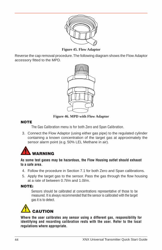
XNX Universal Transmitter Quick Start Guide44
Figure 45. Flow Adaptor
Reverse the cap removal procedure. The following diagram shows the Flow Adaptor accessory fitted to the MPD.
Figure 46. MPD with Flow AdaptorNote
The Gas Calibration menu is for both Zero and Span Calibration.
Connect the Flow Adaptor (using either gas pipe) to the regulated cylinder 3. containing a known concentration of the target gas at approximately the sensor alarm point (e.g. 50% LEL Methane in air).
WARNINGAs some test gases may be hazardous, the Flow Housing outlet should exhaust to a safe area.
Follow the procedure in Section 7.1 for both Zero and Span calibrations.4.
Apply the target gas to the sensor. Pass the gas through the flow housing 5. at a rate of between 0.7l/m and 1.0l/m.
Note:Sensors should be calibrated at concentrations representative of those to be measured. It is always recommended that the sensor is calibrated with the target gas it is to detect.
cAutIoNWhere the user calibrates any sensor using a different gas, responsibility for identifying and recording calibration rests with the user. Refer to the local regulations where appropriate.

XNX Universal Transmitter Quick Start Guide 45
Ensure that the sensor and the vicinity around it is clear all traces of the 6. calibration gas before continuing. This is to avoid triggering spurious alarms. If calibration fails at any point discard the cartridge and replace with a new one.
Remove the test equipment, refit the weatherproof cap to the sensor (if 7. previously removed for the test) and return the system to normal operation.
6�1�6 Cross Calibration procedure for MPD-CB1
cAutIoN Where the user calibrates any sensor using a different gas, responsibility for identifying and recording calibration rests with the user. Refer to the local regulations where appropriate.
When the MPD-CB1 Combustible LEL sensor is to be calibrated with a gas which is different to the gas or vapor to be detected, the following cross calibration procedure should be followed:
Note Table 1 lists the gases according to the reaction they produce at a given • detector.
An eight star (8*) gas produces the highest output, while a one star (1*) • gas produces the lowest output. (These are not applicable at ppm levels.)
Gas Star Rating Gas Star Rating
Acetone 4* Hexane 3*
Ammonia 7* Hydrogen 6*
Benzene 3* Methane 6*
Butanone 3* Methanol 5*
Butane 4* MIBK 3*
Butyl acetate 1* Octane 3*
Butyl acrylate 1* Pentane 3*
Cyclohexane 3* Propane 5*
Cyclohexanone <1* Propan-2-ol 4*
Diethyl ether 4* Styrene 2*
Ethane 6* Tetra hydrafuran 4*
Ethanol 5* Toluene 3*
Ethyl acetate 3* Triethylamine 3*
Ethylene 5* Xylene 2*
Heptane 3* Table 1. Star Rating of Gases
To cross calibrate the MPD-CB1 combustible gas sensor:
Obtain the star rating for both the test gas and the gas to be detected from 1. Table 1.
These values may then be used in Table 2 to obtain the required meter 2. setting when a 50% LEL test gas is applied to the detector.
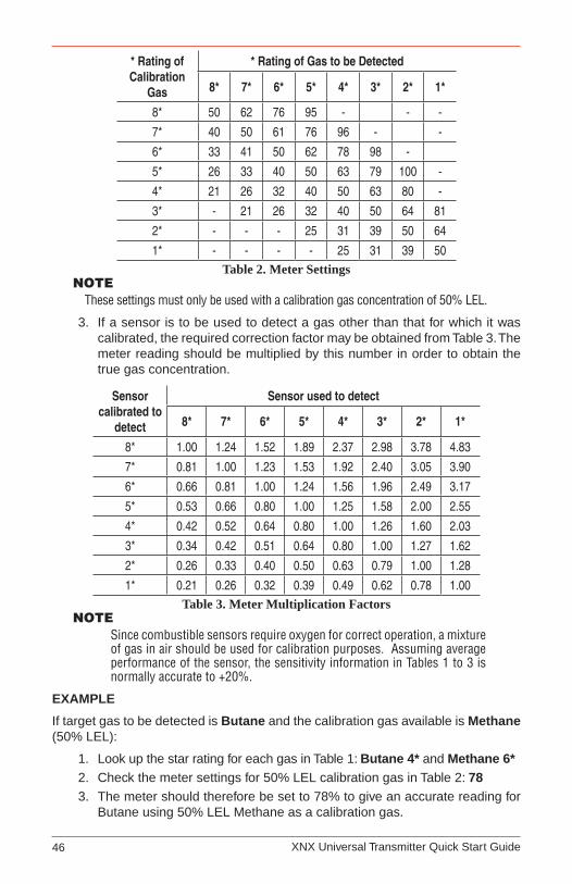
XNX Universal Transmitter Quick Start Guide46
* Rating of Calibration
Gas
* Rating of Gas to be Detected
8* 7* 6* 5* 4* 3* 2* 1*
8* 50 62 76 95 - - -
7* 40 50 61 76 96 - -
6* 33 41 50 62 78 98 -
5* 26 33 40 50 63 79 100 -
4* 21 26 32 40 50 63 80 -
3* - 21 26 32 40 50 64 81
2* - - - 25 31 39 50 64
1* - - - - 25 31 39 50Table 2. Meter Settings
NoteThese settings must only be used with a calibration gas concentration of 50% LEL.
If a sensor is to be used to detect a gas other than that for which it was 3. calibrated, the required correction factor may be obtained from Table 3. The meter reading should be multiplied by this number in order to obtain the true gas concentration.
Sensor calibrated to
detect
Sensor used to detect
8* 7* 6* 5* 4* 3* 2* 1*
8* 1.00 1.24 1.52 1.89 2.37 2.98 3.78 4.83
7* 0.81 1.00 1.23 1.53 1.92 2.40 3.05 3.90
6* 0.66 0.81 1.00 1.24 1.56 1.96 2.49 3.17
5* 0.53 0.66 0.80 1.00 1.25 1.58 2.00 2.55
4* 0.42 0.52 0.64 0.80 1.00 1.26 1.60 2.03
3* 0.34 0.42 0.51 0.64 0.80 1.00 1.27 1.62
2* 0.26 0.33 0.40 0.50 0.63 0.79 1.00 1.28
1* 0.21 0.26 0.32 0.39 0.49 0.62 0.78 1.00Table 3. Meter Multiplication Factors
Note Since combustible sensors require oxygen for correct operation, a mixture of gas in air should be used for calibration purposes. Assuming average performance of the sensor, the sensitivity information in Tables 1 to 3 is normally accurate to +20%.
EXAMPLE
If target gas to be detected is Butane and the calibration gas available is Methane (50% LEL):
Look up the star rating for each gas in Table 1: 1. Butane 4* and Methane 6*Check the meter settings for 50% LEL calibration gas in Table 2: 2. 78The meter should therefore be set to 78% to give an accurate reading for 3. Butane using 50% LEL Methane as a calibration gas.
XNX Universal Transmitter Quick Start Guide 47
Note It is important to calibrate the sensor at the approximate alarm levels to allow for non-linearity of the sensors at gas concentrations above 80% LEL.
6�1�7 Calibrating the 705/705HT
For more complete calibration and configuration information, see the Type 705 Operating Instructions (p/n:00705M5002).
6�1�8 Calibrating the Sensepoint/Sensepoint HT
For more complete calibration and configuration information, see the Sieger Sensepoint Technical Handbook (p/n:2106M0502).
6�1�9 Calibrating the Searchline Excel and Searchpoint Optima Plus
Complete calibration and configuration information can be found in the Searchline Excel Technical Handbook (p/n:2104M0506) and the Searchpoint Optima Plus Operating Instructions (p/n:2108M0501).
6�2 Functional Gas Testing (Bump Test)
WARNINGIt is recommended to bump test the sensors frequently to ensure proper operation.
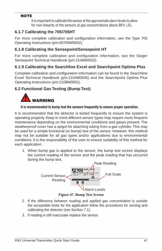
It is recommended that the detector is tested frequently to ensure the system is operating properly. Keep in mind different sensor types may require more frequent maintenance depending on the environmental conditions and gases present. The weatherproof cover has a spigot for attaching tubing from a gas cylinder. This may be used for a simple functional (or bump) test of the sensor. However, this method may not be suitable for all gas types and/or applications due to environmental conditions. It is the responsibility of the user to ensure suitability of this method for each application.
When bump gas is applied to the sensor, the bump test screen displays 1. the current reading of the sensor and the peak reading that has occurred during the bump test.
Peak Reading
Full Scale
Alarm Levels
Current SensorReading
Figure 47. Bump Test Screen
If the difference between reading and applied gas concentration is outside 2. the acceptable limits for the application follow the procedures for zeroing and calibrating the detector (see Section 7.1).
If reading is still inaccurate replace the sensor.3.

XNX Universal Transmitter Quick Start Guide48
7 X
NX
Ele
ctro
chem
ical
Sen
sor
Dat
a
Targ
et G
asCa
rtrid
ge
Part
No
Max
imum
Ra
nge
Sele
ctab
le
Rang
eIn
crem
ent
Defa
ult
Rang
eCa
l Gas
Ran
geCa
l Gas
P/N
Cal G
as
Desc
riptio
n
O2
Oxy
gen
XNX-
XS01
SS25
.0 %
Vol
N/A
N/A
25.0
%Vo
l20
.9 %
Vol
N/A
N/A
H2S
Hyd
roge
n Su
lfide
(Low
Low
Ran
ge)
XNX-
XSH
3SS
15.0
ppm
N/A
N/A
15.0
ppm
5.0
to 1
0.0
ppm
GFV
263
10 p
pm H
2S H
2SH
ydro
gen
Sulfi
de (L
ow R
ange
)XN
X-XS
H1S
S50
.0 p
pm10
.0 to
50.
0 pp
m0.
1 pp
m50
.0 p
pm3
to 3
5 pp
mG
FV25
825
ppm
H2S
H2S
Hyd
roge
n Su
lfide
(Hig
h R
ange
)XN
X-XS
H2S
S50
0 pp
m50
to 5
00 p
pm10
ppm
100
ppm
15 to
350
ppm
GFV
421
50 p
pm H
2S C
OC
arbo
n M
onox
ide
XNX-
XSC
1SS
1,00
0 pp
m10
0 to
1,0
00 p
pm10
0 pp
m30
0 pp
m30
to 2
00 p
pmG
FV29
510
0 pp
m C
O
SO2
Sulfu
r Dio
xide
(Low
Ran
ge)
XNX-
XSS1
SS20
.0 p
pm5.
0 to
20.
0 pp
m5.
0 pp
m15
.0 p
pm2
to 1
4 pp
mC
onta
ct H
A7.
5 pp
m S
O2
SO2
Sulfu
r Dio
xide
(Hig
h R
ange
)XN
X-XS
S2SS
50.0
ppm
20.0
to 5
0.0
ppm
10 p
pm50
.0 p
pm6
to 3
5 pp
mG
FV44
125
ppm
SO
2 N
H3
Amm
onia
(Low
Ran
ge)
XNX-
XSA1
SS20
0 pp
m50
to 2
00 p
pm50
ppm
200
ppm
150
to 1
40 p
pmC
onta
ct H
A10
0 pp
m N
H3
NH
3Am
mon
ia (H
igh
Ran
ge)
XNX-
XSA2
SS10
00 p
pm20
0 to
1,0
00 p
pm50
ppm
1,00
0 pp
m60
to 7
00 p
pmC
onta
ct H
A30
0 pp
m N
H3
Cl 2
Chl
orin
e (L
ow R
ange
)XN
X-XS
L2SS
5.00
ppm
N/A
N/A
5.00
ppm
2 to
3 p
pmG
FV25
12
ppm
Cl 2 in
N2
Cl 2
Chl
orin
e (H
igh
Ran
ge)
XNX-
XSL1
SS20
.0 p
pm5.
0 to
20.
0 pp
m5.
0 pp
m5.
0 pp
m2
to 1
4 pp
mG
FV25
12
ppm
Cl 2 in
N2
ClO
2C
hlor
ine
Dio
xide
XNX-
XSX1
SS1.
00 p
pmN
/AN
/A1.
00 p
pm0.
3 to
0.7
ppm
Gas
Gen
erat
or0.
5 pp
mN
ON
itrog
en M
onox
ide
XNX-
XSM
1SS
100
ppm
N/A
N/A
100
ppm
30 to
70
ppm
GFV
216
50 p
pm N
O in
N2
NO
2N
itrog
en D
ioxi
deXN
X-XS
N1S
S50
.0 p
pm5.
0 to
50.
0 pp
m5.
0 pp
m10
.0 p
pm2
to 3
5 pp
mG
FV43
55
ppm
NO
2 H
2H
ydro
gen
(Low
Ran
ge)
XNX-
XSG
1SS
1000
ppm
N/A
N/A
1,00
0 pp
m30
0 to
700
ppm
GFV
364
500
ppm
H2
H2
Hyd
roge
n (H
igh
Ran
ge)
XNX-
XSG
2SS
10,0
00 p
pmN
/AN
/A10
,000
ppm
3,00
0 to
7,0
00 p
pmC
onta
ct H
A50
00 p
pm H
2 in N
2
HF
Hyd
roge
n Fl
uorid
eXN
X-XS
F1SS
12.0
ppm
N/A
N/A
12.0
ppm
4 to
8 p
pmC
onta
ct H
A5
ppm
HC
l in
N2
PH3
Phos
phin
eXN
X-XS
P1SS
1.20
ppm
N/A
N/A
1.20
ppm
0.5
to 0
.7 p
pmG
FV40
50.
5 pp
m P
H3 in
N2

XNX Universal Transmitter Quick Start Guide 49
8 X
NX
Cat
alyt
ic B
ead
an
d IR
Rep
lace
men
t S
enso
r C
artr
idg
es
Sens
or Ty
peTa
rget
Gas
Cart
ridge
Par
t No
Max
imum
Ra
nge
Sele
ctab
le R
ange
Incr
emen
tDe
faul
t Ra
nge
Cal G
as R
ange
Cal G
as
P/N
Cal G
as D
escr
iptio
n
MPD
-IC1
Car
bon
Dio
xide
IR-C
O2
5.00
%Vo
l1.
00 to
5.0
0 %
Vol
1.00
%Vo
l5.
00 %
Vol
1.50
to 3
.5 %
Vol
Con
tact
HA
2.5
%VO
L C
O2 in
Air
MPD
-IV1
Met
hane
IR-C
H4
5.00
%Vo
l1.
00 to
5.0
0 %
Vol
1.00
%Vo
l5.
00 %
Vol
1.50
to 3
.5 %
Vol
GFV
352
2.5
%VO
L C
H4 in
Air
MPD
-IF1
Flam
mab
les
IR-H
C10
0 %
LEL
20 to
100
%LE
L10
%LE
L10
0 %
LEL
30 to
70
%LE
LG
FV40
61
%VO
L C
3H8 in
Air
MPD
-CB1
Flam
mab
les
MPD
-CAT
100
%LE
L20
to 1
00 %
LEL
10 %
LEL
100
%LE
L30
to 7
0 %
LEL
GFV
352
50 %
LEL
CH
4 in A
ir
9 W
arn
ing
Mes
sag
es
War
ning
Num
ber
Desc
riptio
nCo
nditi
onRe
cove
ry
W001
XNX
24 V
DC
Sup
ply
Bad
DC
pow
er s
uppl
y at
/bel
ow 1
6VD
C o
r at/a
bove
33
VDC
for X
NX
Che
ck P
SU s
tart
volta
ge, c
heck
cab
le lo
op
impe
danc
e, c
heck
term
inal
con
nect
ions
.EC m
V IR
W002
XNX
Tem
pera
ture
War
ning
XNX
inte
rnal
tem
pera
ture
exc
eedi
ng s
tate
d lim
itsC
heck
uni
t loc
atio
n fo
r ext
erna
l hea
t sou
rce,
fit
suns
hade
or o
ther
pro
tect
ion,
pos
sibl
y re
-site
uni
t an
d/or
con
side
r sam
plin
g sy
stem
EC
All p
erso
nalit
ies
mV IR
W003
Sim
ulat
ed W
arni
ng
Sim
ulat
ed w
arni
ng fr
om A
larm
/Fau
lt Si
mul
atio
n
See
Alar
m/F
ault
Sim
ulat
ion.
Afte
r sim
ulat
ion,
rese
t al
l fau
lts a
nd a
larm
s be
fore
exi
ting
‘Ala
rm/F
ault
Sim
ulat
ion’
- the
fron
t pan
el L
ED a
nd re
lays
will
rem
ain
in fa
ult/w
arni
ng/a
larm
mod
e un
til re
set.
EC
All p
erso
nalit
ies
mV IR

XNX Universal Transmitter Quick Start Guide50
War
ning
Num
ber
Desc
riptio
nCo
nditi
onRe
cove
ry
W005
Sens
or Te
mpe
ratu
re W
arni
ng
Sens
or in
tern
al te
mpe
ratu
re e
xcee
ding
lim
itsC
heck
sen
sor l
ocat
ion
for e
xter
nal h
eat s
ourc
e, fi
t su
nsha
de o
r oth
er p
rote
ctio
n, p
ossi
bly
re-s
ite s
enso
r or
con
side
r sam
plin
g sy
stem
ECSe
nsor
Car
tridg
e Te
mpe
ratu
re
mV
N/A
IREx
cel/O
ptim
a Te
mpe
ratu
re
W006
Sens
or N
egat
ive D
rift
Sens
or c
onne
cted
to u
nit h
as a
n in
tern
al 'z
ero'
shi
ft ex
ceed
ing
its s
tate
d lim
its
Che
ck s
enso
r loc
atio
n fo
r ext
erna
l int
erfe
renc
e,
chec
k se
nsor
for o
pera
tion
and
re-z
ero
whe
re
appr
opria
te
EC mV IR
W007
Cal
ibra
tion
Nee
ded
Soon
Cal
ibra
tion
inte
rval
tim
e ex
ceed
ed
Rec
alib
rate
or d
isab
le th
e C
alib
ratio
n In
terv
al -
See
Cal
ibra
tion
Inte
rval
.N
ot
e:
Alth
ough
the
faul
t LED
will
be
lit o
n th
e XN
X fro
nt p
anel
, the
faul
t rel
ay W
ILL
NOT
BE A
CTIV
ATED
.
EC
All P
erso
nalit
ies
mV IR
W009
Sens
or 2
4 VD
C S
uppl
y Ba
d
IR s
enso
r con
nect
ed h
as D
C a
t or b
elow
low
er li
mit
Cor
rect
PSU
vol
tage
, ver
ify c
able
loop
impe
danc
e,
verif
y te
rmin
al c
onne
ctio
ns.
ECN
/Am
V IRIR
Sen
sor V
olta
ge -
Exce
l/Opt
ima
W010
Obs
cure
d Be
am o
r Opt
ics
Opt
ical
sen
sor c
onne
cted
is lo
sing
/has
lost
IR s
igna
ls
Che
ck s
enso
r loc
atio
n fo
r ext
erna
l int
erfe
renc
e (o
bstru
ctio
n in
IR p
ath)
, che
ck s
enso
r for
'dirt
y' w
indo
ws.
Che
ck E
xcel
alig
nmen
t; tra
nsm
itter
op
erat
ion
ECN
/Am
V IREx
cel/O
ptim
a
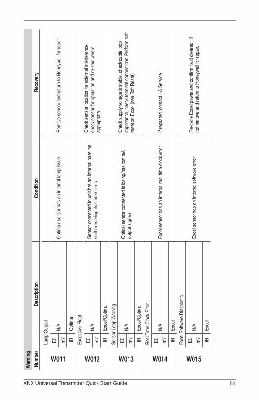
XNX Universal Transmitter Quick Start Guide 51
War
ning
Num
ber
Desc
riptio
nCo
nditi
onRe
cove
ry
W011
Lam
p O
utpu
t
Opt
ima+
sen
sor h
as a
n in
tern
al la
mp
issu
eR
emov
e se
nsor
and
retu
rn to
Hon
eyw
ell f
or re
pair
ECN
/Am
V IRO
ptim
a
W012
Exce
ssive
Flo
at
Sens
or c
onne
cted
to u
nit h
as a
n in
tern
al b
asel
ine
shift
exc
eedi
ng it
s st
ated
lim
its
Che
ck s
enso
r loc
atio
n fo
r ext
erna
l int
erfe
renc
e,
chec
k se
nsor
for o
pera
tion
and
re-z
ero
whe
re
appr
opria
te
ECN
/Am
V IREx
cel/O
ptim
a
W013
Sens
or L
oop
War
ning
Opt
ical
sen
sor c
onne
cted
is lo
sing
/has
lost
mA
outp
ut s
igna
ls
Che
ck s
uppl
y vo
ltage
is s
tabl
e, c
heck
cab
le lo
op
impe
danc
e, c
heck
term
inal
con
nect
ions
. Per
form
sof
t re
set o
n Ex
cel (
see
Soft
Res
et)
ECN
/Am
V IREx
cel/O
ptim
a
W014
Rea
l Tim
e C
lock
Erro
r
Exce
l sen
sor h
as a
n in
tern
al re
al ti
me
cloc
k er
ror
If re
peat
ed, c
onta
ct H
A Se
rvic
eEC
N/A
mV IR
Exce
l
W015
Exce
l Sof
twar
e D
iagn
ostic
Exce
l sen
sor h
as a
n in
tern
al s
oftw
are
erro
rR
e-cy
cle
Exce
l pow
er a
nd c
onfir
m 'f
ault
clea
red'
, if
not r
emov
e an
d re
turn
to H
oney
wel
l for
repa
ir.EC
N/A
mV IR
Exce
l

XNX Universal Transmitter Quick Start Guide52
War
ning
Num
ber
Desc
riptio
nCo
nditi
onRe
cove
ry
W016
Inst
alla
tion
Not
Com
plet
ed
Exce
l sen
sor h
as n
ot c
ompl
eted
a 'f
ull' i
nsta
llatio
n pr
oced
ure
Che
ck E
xcel
alig
nmen
t and
con
firm
ope
ratin
g di
stan
ce, r
erun
'inst
alla
tion
proc
edur
e'EC
N/A
mV IR
Exce
l
W018
Gen
eral
Dia
gnos
tic
EC
All P
erso
nalit
ies
mV IR
W019
Inte
rnal
Pow
er S
uppl
y D
efec
t
5V p
ower
sup
ply
failu
re in
Exc
el re
ceive
rR
emov
e an
d re
turn
to H
oney
wel
l for
repa
ir.EC
N/A
mV IR
Exce
l
W020
Forc
ed m
A Ti
meo
ut
XNX
left
in fo
rce
mA
mod
e to
o lo
ngEx
it Fo
rce
mA
mod
e. S
ee F
orce
mA
Out
put.
EC
All P
erso
nalit
ies
mV IR
W021
Forc
e R
elay
Tim
eout
XNX
in fo
rce
rela
y m
ode
too
long
Exit
Forc
e R
elay
mod
e. S
ee F
orce
Rel
ays.
EC
All P
erso
nalit
ies
mV IR
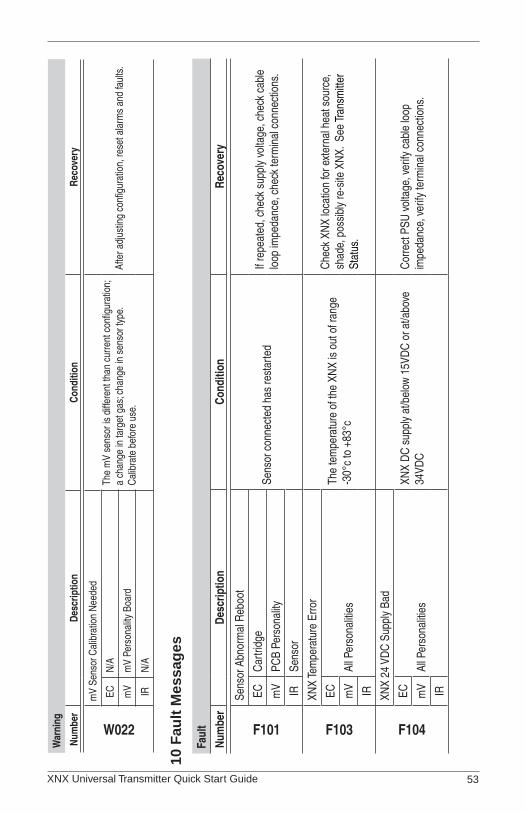
XNX Universal Transmitter Quick Start Guide 53
War
ning
Num
ber
Desc
riptio
nCo
nditi
onRe
cove
ry
W022
mV
Sens
or C
alib
ratio
n N
eede
dTh
e m
V se
nsor
is d
iffer
ent t
han
curre
nt c
onfig
urat
ion;
a
chan
ge in
targ
et g
as; c
hang
e in
sen
sor t
ype.
C
alib
rate
bef
ore
use.
Afte
r adj
ustin
g co
nfigu
ratio
n, re
set a
larm
s an
d fa
ults
.EC
N/A
mV
mV
Pers
onal
ity B
oard
IRN
/A
10 F
ault
Mes
sag
es
Faul
t
Num
ber
Desc
riptio
nCo
nditi
onRe
cove
ry
F101
Sens
or A
bnor
mal
Reb
oot
Sens
or c
onne
cted
has
rest
arte
dIf
repe
ated
, che
ck s
uppl
y vo
ltage
, che
ck c
able
lo
op im
peda
nce,
che
ck te
rmin
al c
onne
ctio
ns.
ECC
artri
dge
mV
PCB
Pers
onal
ity
IRSe
nsor
F103
XNX
Tem
pera
ture
Erro
r
The
tem
pera
ture
of t
he X
NX
is o
ut o
f ran
ge
-30°
c to
+83
°c
Che
ck X
NX
loca
tion
for e
xter
nal h
eat s
ourc
e,
shad
e, p
ossi
bly
re-s
ite X
NX.
See
Tran
smitt
er
Stat
us.
EC
All P
erso
nalit
ies
mV IR
F104
XNX
24 V
DC
Sup
ply
Bad
XNX
DC
sup
ply
at/b
elow
15V
DC
or a
t/abo
ve
34VD
CC
orre
ct P
SU v
olta
ge, v
erify
cab
le lo
op
impe
danc
e, v
erify
term
inal
con
nect
ions
.EC
All P
erso
nalit
ies
mV IR
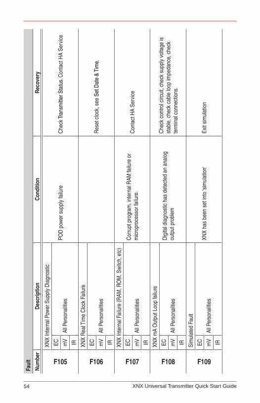
XNX Universal Transmitter Quick Start Guide54
Faul
t
Num
ber
Desc
riptio
nCo
nditi
onRe
cove
ry
F105
XNX
Inte
rnal
Pow
er S
uppl
y D
iagn
ostic
POD
pow
er s
uppl
y fa
ilure
Che
ck Tr
ansm
itter
Sta
tus.
Con
tact
HA
Serv
ice
EC
All P
erso
nalit
ies
mV IR
F106
XNX
Rea
l Tim
e C
lock
Fai
lure
Res
et c
lock
, see
Set
Dat
e &
Tim
e.EC
All P
erso
nalit
ies
mV IR
F107
XNX
Inte
rnal
Fai
lure
(RAM
, RO
M, S
witc
h, e
tc)
Cor
rupt
pro
gram
, int
erna
l RAM
failu
re o
r m
icro
proc
esso
r fai
lure
.C
onta
ct H
A Se
rvic
eEC
All P
erso
nalit
ies
mV IR
F108
XNX
mA
Out
put L
oop
failu
re
Dig
ital d
iagn
ostic
has
det
ecte
d an
ana
log
outp
ut p
robl
em
Che
ck c
ontro
l circ
uit,
chec
k su
pply
vol
tage
is
stab
le, c
heck
cab
le lo
op im
peda
nce,
che
ck
term
inal
con
nect
ions
.
EC
All P
erso
nalit
ies
mV IR
F109
Sim
ulat
ed F
ault
XNX
has
been
set
into
'sim
ulat
ion'
Ex
it si
mul
atio
nEC
All P
erso
nalit
ies
mV IR
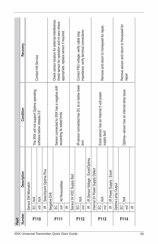
XNX Universal Transmitter Quick Start Guide 55
Faul
t
Num
ber
Desc
riptio
nCo
nditi
onRe
cove
ry
F110
Sens
or S
W M
ism
atch
The
XNX
will
not s
uppo
rt O
ptim
a op
erat
ing
softw
are
belo
w re
leas
e 3.
0C
onta
ct H
A Se
rvic
eEC
N/A
mV
N/A
IRSe
arch
poin
t Opt
ima
Plus
F111
Neg
ative
Drif
t
Sens
or c
onne
cted
to X
NX
has
a ne
gativ
e dr
ift
exce
edin
g its
sta
ted
limits
Che
ck s
enso
r loc
atio
n fo
r ext
erna
l int
erfe
renc
e,
chec
k se
nsor
for o
pera
tion
and
re-z
ero
whe
re
appr
opria
te, r
epla
ce s
enso
r if r
equi
red.
EC
All P
erso
nalit
ies
mV IR
F112
Sens
or 2
4 VD
C S
uppl
y Ba
d
IR s
enso
r con
nect
ed h
as D
C a
t or b
elow
low
er
limit
Cor
rect
PSU
vol
tage
, ver
ify c
able
loop
im
peda
nce,
ver
ify te
rmin
al c
onne
ctio
ns.
ECN
/Am
V IRIR
Sen
sor V
olta
ge -
Exce
l/Opt
ima
F113
Inte
rnal
5V
Pow
er S
uppl
y D
efec
t
Exce
l sen
sor h
as a
n in
tern
al 5
vol
t pow
er
supp
ly fa
ult
Rem
ove
and
retu
rn to
Hon
eyw
ell f
or re
pair.
ECN
/Am
V IRIR
Pow
er S
uppl
y - E
xcel
F114
Opt
ima
Lam
p O
utpu
t
Opt
ima+
sen
sor h
as a
n in
tern
al la
mp
issu
eR
emov
e se
nsor
and
retu
rn to
Hon
eyw
ell f
or
repa
irEC
N/A
mV IR
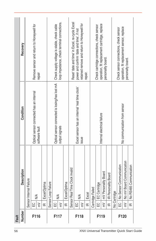
XNX Universal Transmitter Quick Start Guide56
Faul
t
Num
ber
Desc
riptio
nCo
nditi
onRe
cove
ry
F116
Sens
or In
tern
al F
ailu
re
Opt
ical
sen
sor c
onne
cted
has
an
inte
rnal
so
ftwar
e fa
ult
Rem
ove
sens
or a
nd re
turn
to H
oney
wel
l for
re
pair
ECN
/Am
V IREx
cel/O
ptim
a
F117
Sens
or L
oop
Failu
re
Opt
ical
sen
sor c
onne
cted
is lo
sing
/has
lost
mA
outp
ut s
igna
lsC
heck
sup
ply
volta
ge is
sta
ble,
che
ck c
able
lo
op im
peda
nce,
che
ck te
rmin
al c
onne
ctio
ns.
ECN
/Am
V IREx
cel/O
ptim
a
F118
Sens
or R
eal T
ime
Clo
ck in
valid
Exce
l sen
sor h
as a
n in
tern
al 'r
eal t
ime
cloc
k' is
sue
Res
et 'd
ate
and
time'
in E
xcel
, re-
cycl
e Ex
cel
pow
er a
nd c
onfir
m 'd
ate
and
time'
, if n
ot
reta
ined
rem
ove
and
retu
rn to
Hon
eyw
ell f
or
repa
ir.
ECN
/Am
V IREx
cel
F119
Car
tridg
e Fa
iled
Inte
rnal
ele
ctric
al fa
ilure
Che
ck c
artri
dge
conn
ectio
ns, c
heck
sen
sor
oper
atio
n, fi
t rep
lace
men
t car
tridg
e, re
plac
e pe
rson
ality
boa
rd.
ECEC
Car
tridg
e
mV
mV
Pers
onal
ity B
oard
IRIR
Per
sona
lity
Boar
d
F120
No
Car
tridg
e
No
com
mun
icat
ion
from
sen
sor
Che
ck s
enso
r con
nect
ions
, che
ck s
enso
r op
erat
ion,
fit r
epla
cem
ent s
enso
r, re
plac
e pe
rson
alty
boa
rd.
ECN
o Se
nsor
Com
mun
icat
ion
mV
No
mV
Boar
d C
omm
unic
atio
n
IRN
o R
S485
Com
mun
icat
ion
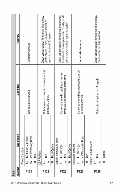
XNX Universal Transmitter Quick Start Guide 57
Faul
t
Num
ber
Desc
riptio
nCo
nditi
onRe
cove
ry
F121
Wro
ng C
artri
dge
Gas
par
amet
ers
inva
lid
Con
tact
HA
Serv
ice.
ECEC
Sen
sor C
artri
dge
mV
mV
Pers
onal
ity B
oard
IRN
/A
F122
DSP
Pro
blem
Opt
ical
sen
sor c
onne
cted
is lo
sing
/has
lost
pr
oces
sing
sig
nals
Che
ck s
enso
r loc
atio
n fo
r ext
erna
l int
erfe
renc
e (o
bstru
ctio
n in
IR p
ath)
, rem
ove
and
retu
rn
sens
or to
Hon
eyw
ell f
or re
pair.
.
ECN
/Am
V IREx
cel/O
ptim
a
F123
Sens
or Te
mpe
ratu
re E
rror
Sens
or c
onne
cted
to u
nit h
as a
n in
tern
al
tem
pera
ture
exc
eedi
ng it
s st
ated
lim
its
Che
ck s
enso
r loc
atio
n fo
r ext
erna
l hea
t sou
rce,
fit
sun
shad
e or
oth
er p
rote
ctio
n, p
ossi
bly
re-s
ite
sens
or a
nd/o
r con
side
r sam
plin
g sy
stem
ECEC
Car
tridg
e
mV
N/A
IREx
cel/O
ptim
a
F125
Cal
ibra
tion
Req
uire
d
Sens
or c
onne
cted
has
exc
eede
d m
axim
um
calib
ratio
n in
terv
alR
e-ca
libra
te th
e se
nsor
ECEC
Car
tridg
e
mV
mV
Pers
onal
ity B
oard
IRN
/A
F126
Sam
ple
Path
Obs
cure
d
Opt
ima
is lo
sing
/has
lost
IR s
igna
lsC
heck
sen
sor l
ocat
ion
for e
xter
nal i
nter
fere
nce,
ch
eck
sens
or fo
r 'di
rty' w
indo
ws.
ECN
/Am
V IRO
ptim
a
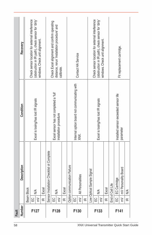
XNX Universal Transmitter Quick Start Guide58
Faul
t
Num
ber
Desc
riptio
nCo
nditi
onRe
cove
ry
F127
Beam
Blo
ck
Exce
l is
losi
ng/h
as lo
st IR
sig
nals
Che
ck s
enso
r loc
atio
n fo
r ext
erna
l int
erfe
renc
e (o
bstru
ctio
n in
IR p
ath)
, che
ck s
enso
r for
'dirt
y' w
indo
ws.
Che
ck u
nit a
lignm
ent.
ECN
/Am
V IREx
cel
F128
Sens
or In
stal
latio
n C
heck
list o
t Com
plet
e
Exce
l sen
sor h
as n
ot c
ompl
eted
a 'f
ull'
inst
alla
tion
proc
edur
e
Che
ck E
xcel
alig
nmen
t and
con
firm
ope
ratin
g di
stan
ce, r
erun
'inst
alla
tion
proc
edur
e' a
nd
calib
rate
.
ECN
/Am
V IREx
cel
F130
Opt
ion
com
mun
icat
ion
Failu
re
Inte
rnal
opt
ion
boar
d no
t com
mun
icat
ing
with
XN
X.C
onta
ct H
A Se
rvic
eEC
All P
erso
nalit
ies
mV IR
F133
Low
Opt
ical
Sam
ple
Sign
al
Exce
l is
losi
ng/h
as lo
st IR
sig
nals
Che
ck s
enso
r loc
atio
n fo
r ext
erna
l int
erfe
renc
e (o
bstru
ctio
n in
IR p
ath)
, che
ck s
enso
r for
'dirt
y' w
indo
ws.
Che
ck u
nit a
lignm
ent.
ECN
/Am
V IREx
cel
F141
End
of C
ell L
ife
Inst
alle
d se
nsor
exc
eede
d se
nsor
life
pa
ram
eter
Fit r
epla
cem
ent c
artri
dge.
ECEC
Car
tridg
e
mV
mV
Pers
onal
ity B
oard
IRN
/A

XNX Universal Transmitter Quick Start Guide 59
Faul
t
Num
ber
Desc
riptio
nCo
nditi
onRe
cove
ry
F143
Stab
ilizat
ion
Tim
eout
Sens
or e
xcee
ds n
orm
al w
arm
-up
time
Cyc
le p
ower
, con
tact
HA
Serv
ice
if pr
oble
m
pers
ists
.
ECU
nsta
ble
Sens
or O
utpu
tm
V IRSe
nsor
Exc
eede
d Ex
pect
ed S
tabi
lizat
ion
Tim
e
F145
Refl
ex F
ailu
re
EC c
ell h
as re
ache
d en
d of
life
.Fi
t rep
lace
men
t cel
l or c
artri
dge.
ECEC
Car
tridg
e
mV
N/A
IR
F146
Gen
eral
Opt
ical
Fau
lt
Con
tact
HA
Serv
ice
ECN
/Am
V IREx
cel/O
ptim
a
F148
Opt
ion
Boar
d Fa
ilure
Inte
rnal
opt
ion
boar
d ha
rdwa
re fa
ilure
.C
onta
ct H
A Se
rvic
eEC
All P
erso
nalit
ies
mV IR
F149
Inte
rnal
Com
mun
icat
ion
Failu
re (m
A)
Inte
rnal
4-2
0 m
A m
onito
ring
circ
uit
com
mun
icat
ion
failu
re.
Con
tact
HA
Serv
ice
EC
All P
erso
nalit
ies
mV IR
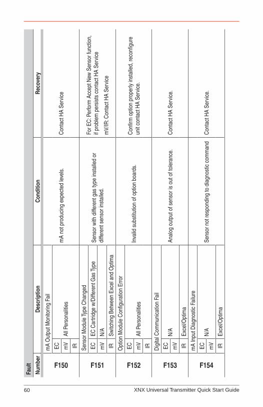
XNX Universal Transmitter Quick Start Guide60
Faul
t
Num
ber
Desc
riptio
nCo
nditi
onRe
cove
ry
F150
mA
Out
put M
onito
ring
Fail
mA
not p
rodu
cing
exp
ecte
d le
vels.
Con
tact
HA
Serv
ice
EC
All P
erso
nalit
ies
mV IR
F151
Sens
or M
odul
e Ty
pe C
hang
ed
Sens
or w
ith d
iffer
ent g
as ty
pe in
stal
led
or
diffe
rent
sen
sor i
nsta
lled.
For E
C: P
erfo
rm A
ccep
t New
Sen
sor f
unct
ion,
if
prob
lem
per
sist
s co
ntac
t HA
Serv
ice
mV/
IR: C
onta
ct H
A Se
rvic
e
ECEC
Car
tridg
e w
/Diff
eren
t Gas
Type
mV
N/A
IRSw
itchi
ng B
etw
een
Exce
l and
Opt
ima
F152
Opt
ion
Mod
ule
Con
figur
atio
n Er
ror
Inva
lid s
ubst
itutio
n of
opt
ion
boar
ds.
Con
firm
opt
ion
prop
erly
inst
alle
d, re
confi
gure
un
it co
ntac
t HA
Serv
ice.
EC
All P
erso
nalit
ies
mV IR
F153
Dig
ital C
omm
unic
atio
n Fa
il
Anal
og o
utpu
t of s
enso
r is
out o
f tol
eran
ce.
Con
tact
HA
Serv
ice.
ECN
/Am
V IREx
cel/O
ptim
a
F154
mA
Inpu
t Dia
gnos
tic F
ailu
re
Sens
or n
ot re
spon
ding
to d
iagn
ostic
com
man
dC
onta
ct H
A Se
rvic
e.EC
N/A
mV IR
Exce
l/Opt
ima
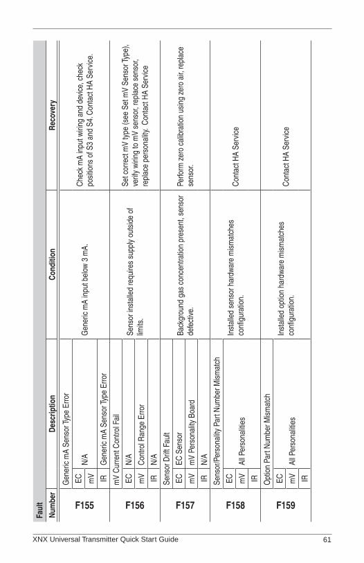
XNX Universal Transmitter Quick Start Guide 61
Faul
t
Num
ber
Desc
riptio
nCo
nditi
onRe
cove
ry
F155
Gen
eric
mA
Sens
or Ty
pe E
rror
Gen
eric
mA
inpu
t bel
ow 3
mA.
Che
ck m
A in
put w
iring
and
dev
ice,
che
ck
posi
tions
of S
3 an
d S4
. Con
tact
HA
Serv
ice.
ECN
/Am
V IRG
ener
ic m
A Se
nsor
Type
Erro
r
F156
mV
Cur
rent
Con
trol F
ail
Sens
or in
stal
led
requ
ires
supp
ly o
utsi
de o
f lim
its.
Set c
orre
ct m
V ty
pe (s
ee S
et m
V Se
nsor
Type
), ve
rify
wiri
ng to
mV
sens
or, r
epla
ce s
enso
r, re
plac
e pe
rson
ality
. C
onta
ct H
A Se
rvic
e
ECN
/A
mV
Con
trol R
ange
Erro
r
IRN
/A
F157
Sens
or D
rift F
ault
Back
grou
nd g
as c
once
ntra
tion
pres
ent,
sens
or
defe
ctive
.Pe
rform
zer
o ca
libra
tion
usin
g ze
ro a
ir, re
plac
e se
nsor
.EC
EC S
enso
r
mV
mV
Pers
onal
ity B
oard
IRN
/A
F158
Sens
or/P
erso
nalit
y Pa
rt N
umbe
r Mis
mat
ch
Inst
alle
d se
nsor
har
dwar
e m
ism
atch
es
confi
gura
tion.
Con
tact
HA
Serv
ice
EC
All P
erso
nalit
ies
mV IR
F159
Opt
ion
Part
Num
ber M
ism
atch
Inst
alle
d op
tion
hard
ware
mis
mat
ches
co
nfigu
ratio
n.C
onta
ct H
A Se
rvic
eEC
All P
erso
nalit
ies
mV IR

XNX Universal Transmitter Quick Start Guide62
Faul
t
Num
ber
Desc
riptio
nCo
nditi
onRe
cove
ry
F160
Har
dwar
e D
iagn
ostic
Fai
lure
Def
ectiv
e EC
car
tridg
e or
mV
pers
onal
ity
boar
d.R
epla
ce E
C c
artri
dge,
con
tact
HA
Serv
ice
ECEC
Car
tridg
e
mV
mV
Pers
onal
ity B
oard
IRN
/A
F161
Faul
t Lev
el m
A In
put F
ailu
re
IR m
A in
put i
ndic
ates
sen
sor f
ailu
re, l
ess
than
1
mA.
Che
ck m
A in
put w
iring
. Con
tact
HA
Serv
ice
ECN
/Am
V IREx
cel/O
ptim
a
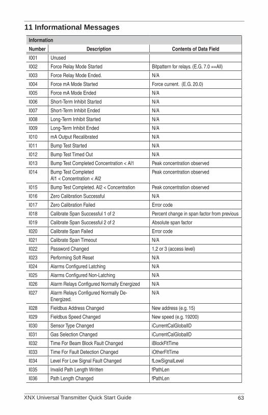
XNX Universal Transmitter Quick Start Guide 63
11 Informational Messages
Information
Number Description Contents of Data Field
I001 Unused
I002 Force Relay Mode Started Bitpattern for relays. (E.G. 7.0 ==All)
I003 Force Relay Mode Ended. N/A
I004 Force mA Mode Started Force current. (E.G. 20.0)
I005 Force mA Mode Ended N/A
I006 Short-Term Inhibit Started N/A
I007 Short-Term Inhibit Ended N/A
I008 Long-Term Inhibit Started N/A
I009 Long-Term Inhibit Ended N/A
I010 mA Output Recalibrated N/A
I011 Bump Test Started N/A
I012 Bump Test Timed Out N/A
I013 Bump Test Completed Concentration < Al1 Peak concentration observed
I014 Bump Test Completed Al1 < Concentration < Al2
Peak concentration observed
I015 Bump Test Completed. Al2 < Concentration Peak concentration observed
I016 Zero Calibration Successful N/A
I017 Zero Calibration Failed Error code
I018 Calibrate Span Successful 1 of 2 Percent change in span factor from previous
I019 Calibrate Span Successful 2 of 2 Absolute span factor
I020 Calibrate Span Failed Error code
I021 Calibrate Span Timeout N/A
I022 Password Changed 1,2 or 3 (access level)
I023 Performing Soft Reset N/A
I024 Alarms Configured Latching N/A
I025 Alarms Configured Non-Latching N/A
I026 Alarm Relays Configured Normally Energized N/A
I027 Alarm Relays Configured Normally De-Energized.
N/A
I028 Fieldbus Address Changed New address (e.g. 15)
I029 Fieldbus Speed Changed New speed (e.g. 19200)
I030 Sensor Type Changed iCurrentCalGlobalID
I031 Gas Selection Changed iCurrentCalGlobalID
I032 Time For Beam Block Fault Changed iBlockFltTime
I033 Time For Fault Detection Changed iOtherFltTime
I034 Level For Low Signal Fault Changed fLowSignalLevel
I035 Invalid Path Length Written fPathLen
I036 Path Length Changed fPathLen

XNX Universal Transmitter Quick Start Guide64
Information
Number Description Contents of Data Field
I037 mA for Inhibit Changed f_mA_Flt_Step[0]
I038 mA for Warning Changed f_mA_Flt_Step[1]
I039 mA for Overrange Changed f_mA_Flt_Step[2]
I040 mA for Fault Changed f_mA_Flt_Step[3]
I041 mA for Low Signal Changed f_mA_Flt_Step[4]
I042 mA for Blocked Beam Changed f_mA_Flt_Step[5]
I043 Concentration for mA Full Scale Changed fDisplayRange
I044 Instrument Id Changed N/A
I045 Measuring Units Changed iMeasurementUnits
I046 Alarm 1 Reconfigured for Increasing Concentrations
N/A
I047 Alarm 1 Reconfigured for Depleting Concentrations
N/A
I048 Alarm 2 Reconfigured for Increasing Concentrations
N/A
I049 Alarm 2 Reconfigured for Depleting Concentrations
N/A
I050 Alarm 1 Value Changed fAlarmThres[0]
I051 Alarm 2 Value Changed fAlarmThres[1]
I052 Clock Set N/A
I053 Date Format Changed iDateFormat
I054 Sensor Boots N/A
I055 Unused
I056 Sensor RTC Adjusted Error in seconds or +/-999 if large
I057 Fault Set Latching
I058 Fault Set Non-Latching
I059 LCD Heater On
I060 LCD Heater Off
I061 Personality Power Up Sensor type
I062 Option Power Up Option type
I063 Loaded Same Cell
I064 Loaded Changed Cell
I065 Loaded Changed Gas
I066 Option Type Changed
I067 Hart Address Changed
I068 Hart Mode Changed
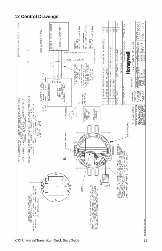
XNX Universal Transmitter Quick Start Guide 65
12 Control Drawings
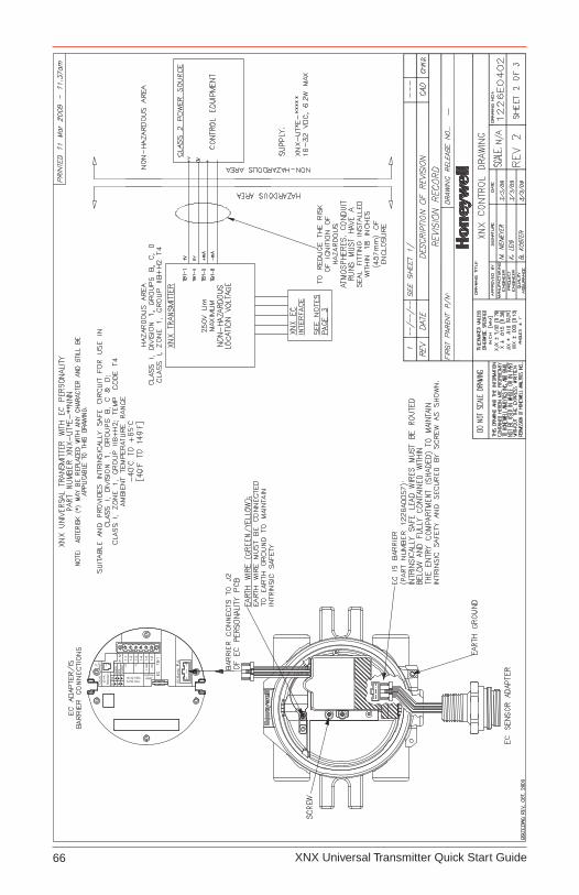
XNX Universal Transmitter Quick Start Guide66

XNX Universal Transmitter Quick Start Guide 67
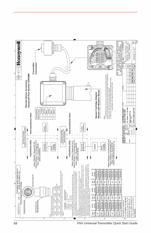
XNX Universal Transmitter Quick Start Guide68


Find out morewww.honeywellanalytics.com
Contact Honeywell Analytics:
AmericasHoneywell Analytics
405 Barclay Boulevard
Lincolnshire, IL 60069
USA
Tel: +1 847 955 8200
Toll free: +1 800 538 0363
Fax: +1 847 955 8208
Europe, Middle East, AfricaLife Safety Distribution AG
Wilstrasse 11-U11
CH-8610 Uster
Switzerland
Tel: +41 (0)44 943 4300
Fax: +41 (0)44 943 4398
Technical [email protected]
www.honeywell.com
Asia PacificHoneywell Analytics Asia Pacific
#508, Kolon Science Valley (1)
187-10 Guro-Dong, Guro-Gu
Seoul, 152-050,
Korea
Tel: +82 (0)2 2025 0307
Fax: +82 (0)2 2025 0329
1998-0744 Release 1
March 2009
© 2009 Honeywell Analytics
Please Note:While every effort has been made to ensure accuracy in this publication, no responsibility can be accepted for errors or omissions.Data may change, as well as legislation, and you are strongly advised to obtain copies of the most recently issued regulations, standards and guidelines.This publication is not intended to form the basis of a contract.