![12851 XNX Foundation Fieldbus MAN0913 Rev1 ES[1]](https://static.fdocuments.us/doc/165x107/55cf9ddd550346d033af942e/12851-xnx-foundation-fieldbus-man0913-rev1-es1.jpg)
XNX Safety Manual
12
XNX TM Universal Transmitter Safety Manual Release 1 03/10 • XNX SIL 2 Certificate • Overview • Safety Parameters • Fault Diagnostic Time Interval • Proof Test • Proof Testing Procedure
-
Upload
gustavo-kemeny -
Category
Documents
-
view
8.433 -
download
6
Transcript of XNX Safety Manual
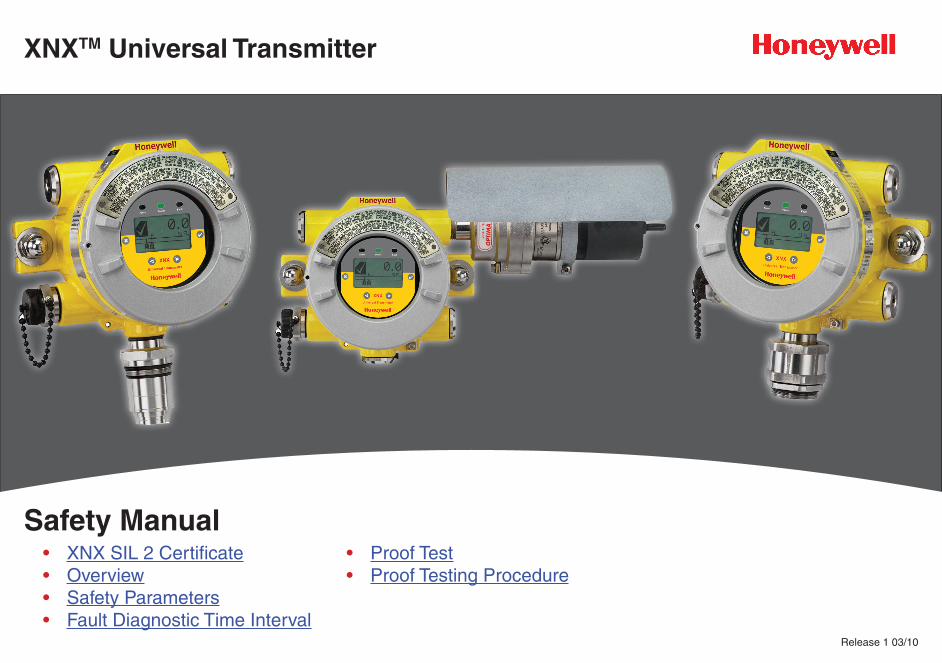
XNXTM Universal Transmitter
Safety Manual
Release 1 03/10
• XNX SIL 2 Certificate• Overview• Safety Parameters• Fault Diagnostic Time Interval
• Proof Test• Proof Testing Procedure
XNX Universal Transmitter
2
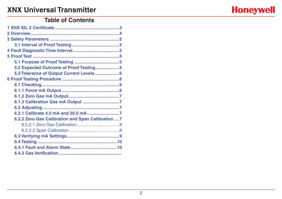
Table of Contents1 XNX SIL 2 Certificate .....................................................32 Overview .........................................................................43 Safety Parameters .........................................................5
3.1 Interval of Proof Testing .......................................54 Fault Diagnostic Time Interval ......................................55 Proof Test .......................................................................5
5.1 Purpose of Proof Testing .....................................55.2 Expected Outcome of Proof Testing ...................55.3 Tolerance of Output Current Levels ....................6
6 Proof Testing Procedure ...............................................66.1 Checking................................................................66.1.1 Force mA Output ...............................................66.1.2 Zero Gas mA Output ..........................................76.1.3 Calibration Gas mA Output ..............................76.2 Adjusting ...............................................................76.2.1 Calibrate 4.0 mA and 20.0 mA ..........................76.2.2 Zero Gas Calibration and Span Calibration ....7
6.2.2.1 Zero Gas Calibration ...................................86.2.2.2 Span Calibration .........................................8
6.3 Verifying mA Settings ...........................................96.4 Testing .................................................................106.4.1 Fault and Alarm State ......................................106.4.2 Gas Verification ....................................................
XNX Universal Transmitter
XNX SIL 2 Certificate 3
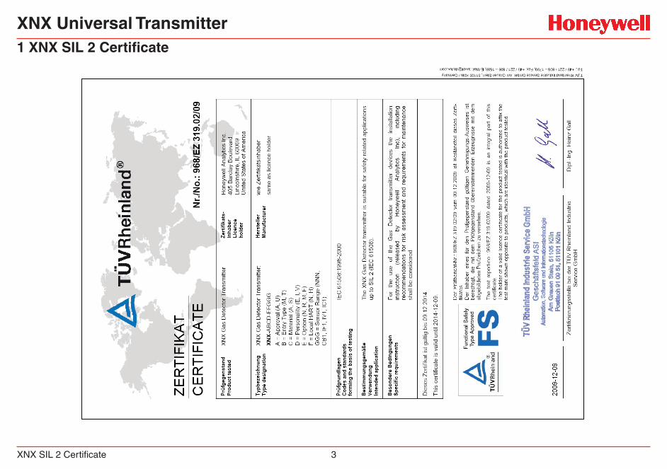
1 XNX SIL 2 Certificate
XNX Universal Transmitter
Overview 4
2 OverviewIEC 61508 is a generic functional safety standard. Functional safety is defined in this standard as “part of the overall safety relating to the Equipment Under Control (EUC) and the EUC control system which depends on the correct functioning of the E/E/PES1 safety related systems, other technology safety-related systems, and external risk reduction facilities.”
A system is considered to be functionally safe if the random and systematic faults do not kill or injure humans, pollute the environment, and do not result in the loss of equipment or production.
A systematic fault is defined as a failure with a definite cause. A random fault can happen at any time and the cause is unclear. The terms fault and failure can be used interchangeably.
A Safety Integrity Level-certified system can detect the majority of safe and unsafe failures. XNX is SIL 2 capable per IEC 61508. XNX is SIL 3 capable in a redundant system per IEC 61508. Table 1 and Table 2 below outline a system’s safety integrity level in relation to its average probability of failure to perform its design function on demand and probability of dangerous failure per hour.
Table 1. Average Probability of Failure to Perform Its Design Function on Demand (Low Demand System)
Safety Integrity Level
Low demand mode of operation (Average probability of failure to perform its design function on demand (PFD))
4 ≥ 10-5 to < 10-4
3 ≥ 10-4 to < 10-3
2 ≥ 10-3 to < 10-2
1 ≥ 10-2 to < 10-1
1 Electrical/electronic/programmable electronic systems
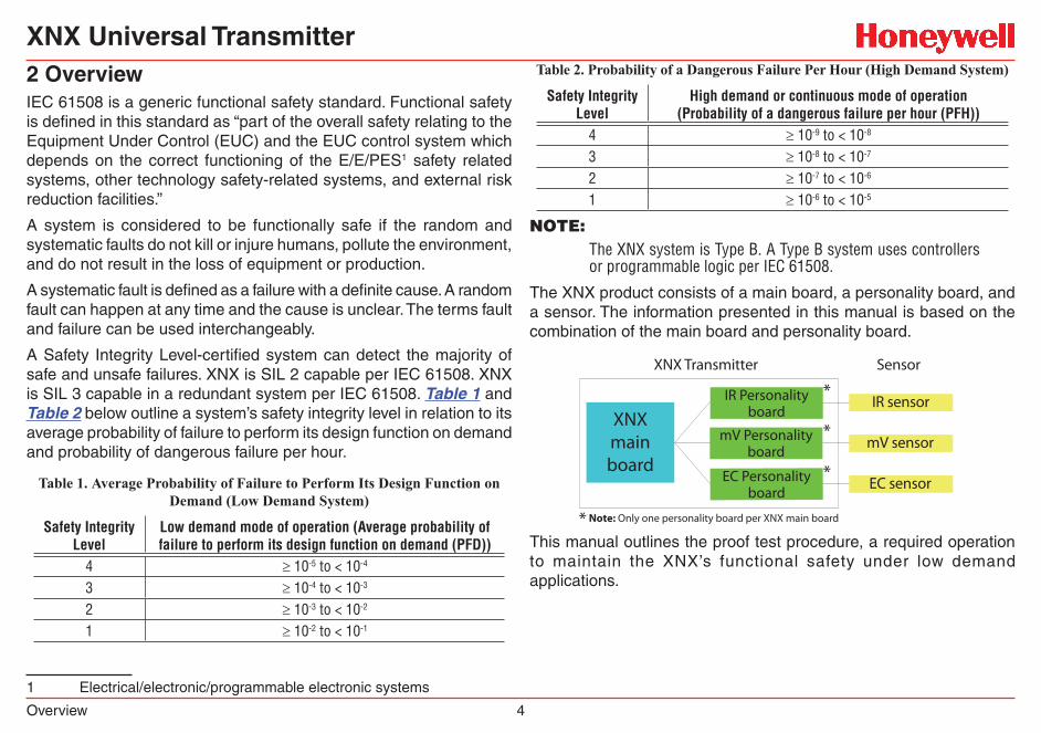
Table 2. Probability of a Dangerous Failure Per Hour (High Demand System)
Safety Integrity Level
High demand or continuous mode of operation (Probability of a dangerous failure per hour (PFH))
4 ≥ 10-9 to < 10-8
3 ≥ 10-8 to < 10-7
2 ≥ 10-7 to < 10-6
1 ≥ 10-6 to < 10-5
NOTE:The XNX system is Type B. A Type B system uses controllers or programmable logic per IEC 61508.
The XNX product consists of a main board, a personality board, and a sensor. The information presented in this manual is based on the combination of the main board and personality board.
XNX main board
IR Personalityboard
EC Personalityboard
IR sensor
mV sensor
EC sensor
XNX Transmitter Sensor
Note: Only one personality board per XNX main board
mV Personalityboard
This manual outlines the proof test procedure, a required operation to maintain the XNX’s functional safety under low demand applications.
XNX Universal Transmitter
Safety Parameters 5 Interval of Proof Testing
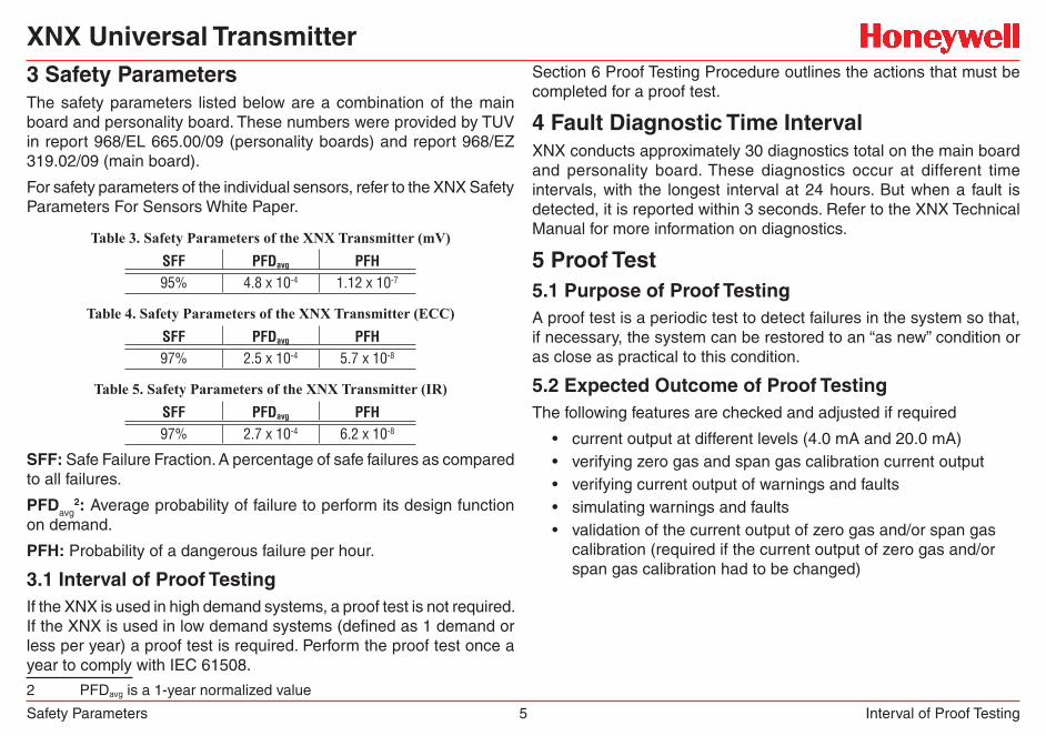
3 Safety ParametersThe safety parameters listed below are a combination of the main board and personality board. These numbers were provided by TUV in report 968/EL 665.00/09 (personality boards) and report 968/EZ 319.02/09 (main board).
For safety parameters of the individual sensors, refer to the XNX Safety Parameters For Sensors White Paper.
Table 3. Safety Parameters of the XNX Transmitter (mV)SFF PFDavg PFH95% 4.8 x 10⁻⁴ 1.12 x 10⁻⁷
Table 4. Safety Parameters of the XNX Transmitter (ECC)SFF PFDavg PFH97% 2.5 x 10⁻⁴ 5.7 x 10⁻⁸
Table 5. Safety Parameters of the XNX Transmitter (IR)SFF PFDavg PFH97% 2.7 x 10⁻⁴ 6.2 x 10⁻⁸
SFF: Safe Failure Fraction. A percentage of safe failures as compared to all failures.
PFDavg2: Average probability of failure to perform its design function
on demand.
PFH: Probability of a dangerous failure per hour.
3.1 Interval of Proof TestingIf the XNX is used in high demand systems, a proof test is not required. If the XNX is used in low demand systems (defined as 1 demand or less per year) a proof test is required. Perform the proof test once a year to comply with IEC 61508.
2 PFDavg is a 1-year normalized value
Section 6 Proof Testing Procedure outlines the actions that must be completed for a proof test.
4 Fault Diagnostic Time IntervalXNX conducts approximately 30 diagnostics total on the main board and personality board. These diagnostics occur at different time intervals, with the longest interval at 24 hours. But when a fault is detected, it is reported within 3 seconds. Refer to the XNX Technical Manual for more information on diagnostics.
5 Proof Test5.1 Purpose of Proof TestingA proof test is a periodic test to detect failures in the system so that, if necessary, the system can be restored to an “as new” condition or as close as practical to this condition.
5.2 Expected Outcome of Proof TestingThe following features are checked and adjusted if required
• current output at different levels (4.0 mA and 20.0 mA) • verifying zero gas and span gas calibration current output• verifying current output of warnings and faults• simulating warnings and faults• validation of the current output of zero gas and/or span gas
calibration (required if the current output of zero gas and/or span gas calibration had to be changed)
XNX Universal Transmitter
Proof Testing Procedure 6 Tolerance of Output Current Levels
5.3 Tolerance of Output Current LevelsThe tolerance for the output current levels is ± 0.1 mA.
Example: If the procedure requires the current output to be 4.0 mA, the actual current reading at the controller end can range from 3.9 mA to 4.1 mA.
6 Proof Testing Procedure6.1 CheckingThe purpose of checking is to ensure the mA output meets the expected levels. If the current does not meet the expected levels, it will have to be adjusted. If, after completing 6.1.1, 6.1.2, and 6.1.3, the mA output does meet the expected levels, proceed to 6.3.
6.1.1 Force mA Output
1. Ensure the current can be measured at the controller end. The current will be measured using the procedures outlined in 6.1.1 to 6.1.3.
2. From the Main Menu, select the Test Menu ( ).
CauTiONThe mA output set in this menu will revert to the normal operating values when exiting the Test Menu. For more information on setting the mA output levels for normal operation, see mA Levels in the XNX Technical Manual.
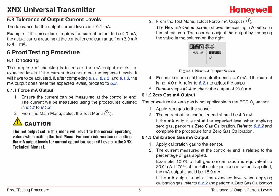
3. From the Test Menu, select Force mA Output ( ).The New mA Output screen shows the existing mA output in the left column. The user can adjust the output by changing the value in the column on the right.
Figure 1. New mA Output Screen
4. Ensure the current at the controller end is 4.0 mA. If the current is not 4.0 mA, refer to 6.2.1 to adjust the output.
5. Repeat steps #2-4 to check the output of 20.0 mA.6.1.2 Zero Gas mA Output
The procedure for zero gas is not applicable to the ECC O2 sensor.
1. Apply zero gas to the sensor. 2. The current at the controller end should be 4.0 mA.
If the mA output is not at the expected level when applying zero gas, perform a Zero Gas Calibration. Refer to 6.2.2 and complete the procedure for a Zero Gas Calibration.
6.1.3 Calibration Gas mA Output
1. Apply calibration gas to the sensor.2. The current measured at the controller end is related to the
percentage of gas applied.Example: 100% of full gas concentration is equivalent to 20.0 mA. If 75% of the full scale gas concentration is applied, the mA output should be 16.0 mA.If the mA output is not at the expected level when applying calibration gas, refer to 6.2.2 and perform a Zero Gas Calibration
XNX Universal Transmitter
Proof Testing Procedure 7 Adjusting
and a Span Gas Calibration.
6.2 AdjustingPerform the following procedures if 4.0 mA and 20.0 mA were not measured at the controller end. If the correct currents were measured, proceed to 6.3.
The current must be measured at the controller end in 6.2.1 and 6.2.2.
6.2.1 Calibrate 4.0 mA and 20.0 mA
1. From the Main Menu, select the Test Menu ( ).
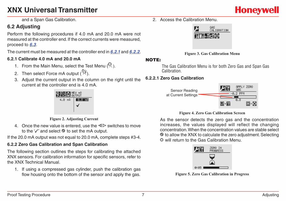
2. Then select Force mA output ( ).3. Adjust the current output in the column on the right until the
current at the controller end is 4.0 mA.
Figure 2. Adjusting Current
4. Once the new value is entered, use the switches to move to the ‘3’ and select ✓ to set the mA output.
If the 20.0 mA output was not equal to 20.0 mA, complete steps #3-4.
6.2.2 Zero Gas Calibration and Span Calibration
The following section outlines the steps for calibrating the attached XNX sensors. For calibration information for specific sensors, refer to the XNX Technical Manual.
1. If using a compressed gas cylinder, push the calibration gas flow housing onto the bottom of the sensor and apply the gas.
2. Access the Calibration Menu.
Figure 3. Gas Calibration MenuNOTE:
The Gas Calibration Menu is for both Zero Gas and Span Gas Calibration.
6.2.2.1 Zero Gas Calibration
Sensor Readingat Current Settings
Figure 4. Zero Gas Calibration Screen
As the sensor detects the zero gas and the concentration increases, the values displayed will reflect the changing concentration. When the concentration values are stable select ✓ to allow the XNX to calculate the zero adjustment. Selecting ✖ will return to the Gas Calibration Menu.
Figure 5. Zero Gas Calibration in Progress
XNX Universal Transmitter
Proof Testing Procedure 8 Adjusting
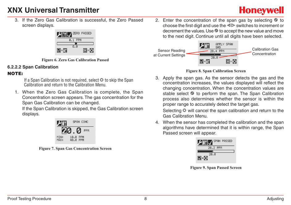
3. If the Zero Gas Calibration is successful, the Zero Passed screen displays.
Figure 6. Zero Gas Calibration Passed
6.2.2.2 Span CalibrationNOTE:
If a Span Calibration is not required, select ✖ to skip the Span Calibration and return to the Calibration Menu.
1. When the Zero Gas Calibration is complete, the Span Concentration screen appears. The gas concentration for the Span Gas Calibration can be changed. If the Span Calibration is skipped, the Gas Calibration screen displays.
Figure 7. Span Gas Concentration Screen
2. Enter the concentration of the span gas by selecting ✓ to choose the first digit and use the switches to increment or decrement the values. Use ✓ to accept the new value and move to the next digit. Continue until all digits have been selected.
Sensor Readingat Current Settings
Calibration GasConcentration
Figure 8. Span Calibration Screen
3. Apply the span gas. As the sensor detects the gas and the concentration increases, the values displayed will reflect the changing concentration. When the concentration values are stable select ✓ to perform the span. The Span Calibration process also determines whether the sensor is within the proper range to accurately detect the target gas.Selecting ✖ will cancel the span calibration and return to the Gas Calibration Menu.
4. When the sensor has completed the calibration and the span algorithms have determined that it is within range, the Span Passed screen will appear.
Figure 9. Span Passed Screen
XNX Universal Transmitter
Proof Testing Procedure 9 Verifying mA Settings
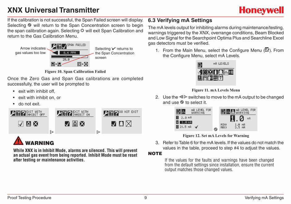
If the calibration is not successful, the Span Failed screen will display. Selecting ✓ will return to the Span Concentration screen to begin the span calibration again. Selecting ✖ will exit Span Calibration and return to the Gas Calibration Menu.
Arrow indicatesgas values too low
Selecting ‘✔’ returns tothe Span Concentrationscreen
Figure 10. Span Calibration Failed
Once the Zero Gas and Span Gas calibrations are completed successfully, the user will be prompted to
• exit with inhibit off,• exit with inhibit on, or• do not exit.
WarNiNgWhile XNX is in Inhibit Mode, alarms are silenced. This will prevent an actual gas event from being reported. Inhibit Mode must be reset after testing or maintenance activities.
6.3 Verifying mA SettingsThe mA levels output for inhibiting alarms during maintenance/testing, warnings triggered by the XNX, overrange conditions, Beam Blocked and Low Signal for the Searchpoint Optima Plus and Searchline Excel gas detectors must be verified.
1. From the Main Menu, select the Configure Menu ( ). From the Configure Menu, select mA Levels.
Figure 11. mA Levels Menu
2. Use the switches to move to the mA output to be changed and use ✓ to select it.
✓ Figure 12. Set mA Levels for Warning
3. Refer to Table 6 for the mA levels. If the values do not match the values in the table, proceed to step #4 to adjust the values.
NOTEIf the values for the faults and warnings have been changed from the default settings since installation, ensure the current output matches those changed values.
XNX Universal Transmitter
Proof Testing Procedure 10 Testing
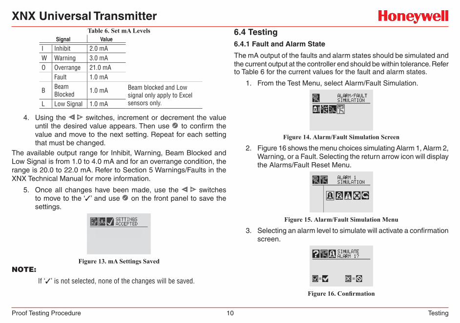
Table 6. Set mA LevelsSignal Value
I Inhibit 2.0 mAW Warning 3.0 mAO Overrange 21.0 mA
Fault 1.0 mA
B Beam Blocked 1.0 mA Beam blocked and Low
signal only apply to Excel sensors only.L Low Signal 1.0 mA
4. Using the switches, increment or decrement the value until the desired value appears. Then use ✓ to confirm the value and move to the next setting. Repeat for each setting that must be changed.
The available output range for Inhibit, Warning, Beam Blocked and Low Signal is from 1.0 to 4.0 mA and for an overrange condition, the range is 20.0 to 22.0 mA. Refer to Section 5 Warnings/Faults in the XNX Technical Manual for more information.
5. Once all changes have been made, use the switches to move to the ‘3’ and use ✓ on the front panel to save the settings.
Figure 13. mA Settings SavedNOTE:
If ‘3’ is not selected, none of the changes will be saved.
6.4 Testing6.4.1 Fault and Alarm State
The mA output of the faults and alarm states should be simulated and the current output at the controller end should be within tolerance. Refer to Table 6 for the current values for the fault and alarm states.
1. From the Test Menu, select Alarm/Fault Simulation.
Figure 14. Alarm/Fault Simulation Screen
2. Figure 16 shows the menu choices simulating Alarm 1, Alarm 2, Warning, or a Fault. Selecting the return arrow icon will display the Alarms/Fault Reset Menu.
Figure 15. Alarm/Fault Simulation Menu
3. Selecting an alarm level to simulate will activate a confirmation screen.
Figure 16. Confirmation
XNX Universal Transmitter
Proof Testing Procedure 11 Testing
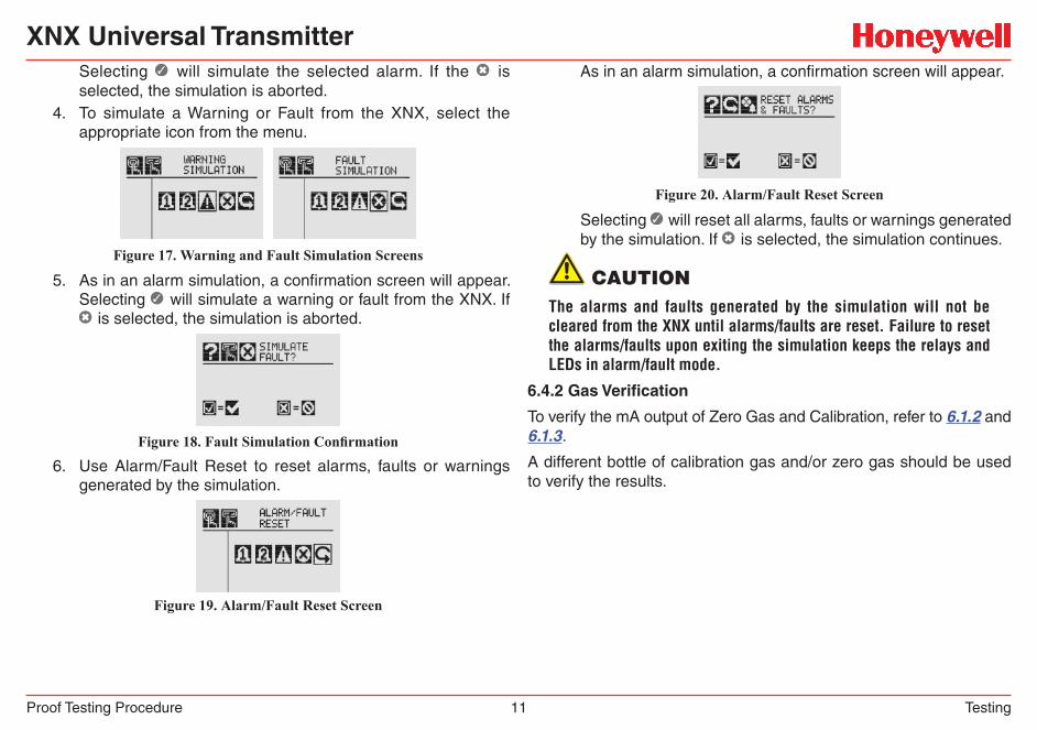
Selecting ✓ will simulate the selected alarm. If the ✖ is selected, the simulation is aborted.
4. To simulate a Warning or Fault from the XNX, select the appropriate icon from the menu.
Figure 17. Warning and Fault Simulation Screens
5. As in an alarm simulation, a confirmation screen will appear. Selecting ✓ will simulate a warning or fault from the XNX. If ✖ is selected, the simulation is aborted.
Figure 18. Fault Simulation Confirmation
6. Use Alarm/Fault Reset to reset alarms, faults or warnings generated by the simulation.
Figure 19. Alarm/Fault Reset Screen
As in an alarm simulation, a confirmation screen will appear.
Figure 20. Alarm/Fault Reset Screen
Selecting ✓ will reset all alarms, faults or warnings generated by the simulation. If ✖ is selected, the simulation continues.
CauTiONThe alarms and faults generated by the simulation will not be cleared from the XNX until alarms/faults are reset. Failure to reset the alarms/faults upon exiting the simulation keeps the relays and LEDs in alarm/fault mode.
6.4.2 Gas Verification
To verify the mA output of Zero Gas and Calibration, refer to 6.1.2 and 6.1.3.
A different bottle of calibration gas and/or zero gas should be used to verify the results.

Find out morewww.honeywellanalytics.com
AmericasHoneywell Analytics405 Barclay BoulevardLincolnshire, IL 60069Tel: +1 847 955 8200Toll free: +1 800 538 0363Fax: +1 847 955 [email protected]
Europe, Middle East, and AfricaLife Safety Distribution AGWilstrasse 11-U11CH-8610 UsterSwitzerlandTel: +41 (0)1 943 4300Fax: +41 (0)1 943 [email protected]
Technical [email protected]
www.honeywell.com
Asia PacificHoneywell Analytics#508, Kolon Science Valley (l)187-10 Guro-Dong, Guro-GuSeoul, 152-050 KoreaTel: +82 2 2025 0300Fax: +82 2 2025 [email protected]
1998-0808
Release 1
March 2010
© 2010 Honeywell Analytics
Please Note:While every effort has been made to ensure accuracy in this publication, no responsibility can be accepted for errors or omissions.Data may change, as well as legislation, and you are strongly advised to obtain copies of the most recently issued regulations, standards and guidelines.This publication is not intended to form the basis of a contract.


![[SAFETY MANUAL] Safety Manual](https://static.fdocuments.us/doc/165x107/61599bfbebe0aa3fed5690dc/safety-manual-safety-manual.jpg)


![[SAFETY MANUAL] Safety Manual - Fresno State](https://static.fdocuments.us/doc/165x107/619b3e164287c02ce855dca4/safety-manual-safety-manual-fresno-state.jpg)