XM-6401B CD-ROM DRIVE PRODUCT SPECIFICATION · The XM-6401B is therefore capable of reproducing...
33
DISK PRODUCTS DIVISION XM-6401B CD-ROM DRIVE PRODUCT SPECIFICATION DECEMBER 1998 REV. 1.0 Specifications are subject to change without notice DOCUMENT NUMBER 11880
Transcript of XM-6401B CD-ROM DRIVE PRODUCT SPECIFICATION · The XM-6401B is therefore capable of reproducing...

DISK PRODUCTS DIVISION
XM-6401BCD-ROM DRIVE
PRODUCT SPECIFICATION
DECEMBER 1998 REV. 1.0
Specifications are subject to change without notice
DOCUMENT NUMBER11880

XM-6401B Rev.1.0
Notice
1.This product has no over-current protection circuit.System should have appropriate over-current protection.Toshiba Corporation makes no warranty of damages caused by no over-current protection.
2.This has a little possibility of errors.To prevent damages and injury caused by the above, careful consideration for the safety and integrity should be taken in the system design.Do not use this product in a system that may cause hazard to human being or material loss caused by the failure, loss of data and/or errors of this product.
3.Do not disassemble or modify this product. Or, reliability, safety and performance can not be guaranteed.
4.Turn off the system power before mounting/removing this product.Or, it may cause failure or damage.
5.Because the DC power socket of this product allows insertion of only one side direction, ascertain direction carefully to insert the plug.
6.To build this product in an equipment, handle it only in electrostatically safe environment.Do not touch connecting terminals directly. Or, the product may be damaged by electrostatic energy.
7. This product can playback discs based on the format described in item 3.1.(1). Do not load a disc which is not based on the item (discs of which outside is cut unevenly and is not a normal circle, etc.) or a disc with its weight unbalanced excessively.A very high speed rotation is carried out inside the product, so abnormal vibration and malfunction mayoccur if disc described above is loaded.
8. When a disc cannot be ejected because of some troubles, etc., turn off the unit and eject the disc usingthe emergency eject mechanism after passing more than 1 minute.When the emergency eject is carried out while the power is on or immediately after the power off, the disc may be eject in a rotating status. We do not assure if the disc is damaged by this.
9. When you close the tray, power must not be turned off. If the tray is pushed in with the hand duringpower-off, a breakdown may occur because the mechanism in the product is not in the transitionstate during power-off.

XM-6401B Rev.1.0
10. As for mounting bracket to incorporate this product into an equipment,(1) When this product is incorporated into an equipment by using the mounting screw hole in the right
and left side planes, the clearance between this product and the mounting bracket is too wide;(2) When this product is incorporated into an equipment by using the screw hole mounting in the bottom,
the surface of the mounting bracket is contorted.If you use such mounting bracket as the above, this product will become deformed, which may cause operation failure. Therefore, it is necessary to take account of the mounting bracket which has the tolerances shown in Fig.1 or whose structure cannot cause this product to deform, as shown in Fig.2
146 +/ - 0.3
146.3+ 0.2- 0
Flatness:less than 0.5mm
Fig.1
this product this product
before the fixing after the fixing
mounting bracket
Fig.2
11. In the instruction manual of your product, statement described in “Safety Instruction Manual “attachedto this product, the statement of item 2 ,7 and 9 above, and other required statements should be
mentioned for thorough understanding by the users.

XM-6401B Rev.1.0
Contents
1. Introduction ---------------------------------------------------------------------------------------------------------------------- 1
2. Features --------------------------------------------------------------------------------------------------------------------------- 2
3. Specifications ------------------------------------------------------------------------------------------------------------------ 33.1. Performance ------------------------------------------------------------------------------------------------------------- 33.2. Environmental Conditions ------------------------------------------------------------------------------------------ 4
3.2.1. Temperature and Humidity ----------------------------------------------------------------------------------- 43.2.2. Dust and Dirt ------------------------------------------------------------------------------------------------------- 43.2.3. Vibration ------------------------------------------------------------------------------------------------------------ 5
3.2.4. Atmospheric Pressure and Altitude ------------------------------------------------------------------- 53.2.5. Shock -------------------------------------------------------------------------------------------------------------- 5
3.3. Installation Conditions ----------------------------------------------------------------------------------------------- 63.4. Dimensions and Mass ----------------------------------------------------------------------------------------------- 63.5. Reliabilities ---------------------------------------------------------------------------------------------------------------- 9
3.5.1. Error Rate ------------------------------------------------------------------------------------------------------------ 93.5.2. MTBF ------------------------------------------------------------------------------------------------------------------ 93.5.3. MTTR ------------------------------------------------------------------------------------------------------------------ 93.5.4. Drive Life ------------------------------------------------------------------------------------------------------------- 9
4. Configuration ------------------------------------------------------------------------------------------------------------------- 94.1. Electrical Circuits ------------------------------------------------------------------------------------------------------- 94.2. Optical Pickup ---------------------------------------------------------------------------------------------------------- 94.3. Spindle Motor ----------------------------------------------------------------------------------------------------------- 94.4. Feed Motor --------------------------------------------------------------------------------------------------------------- 94.5. Load/Eject Motor ------------------------------------------------------------------------------------------------------ 9
5. Functions ------------------------------------------------------------------------------------------------------------------------115.1. CD-ROM Data Configurations -------------------------------------------------------------------------------------115.2. ON/OFF Timing -------------------------------------------------------------------------------------------------------11
6. Interfaces ------------------------------------------------------------------------------------------------------------------------126.1. Signal Lines --------------------------------------------------------------------------------------------------------------12
6.1.1. Signal Line Termination ---------------------------------------------------------------------------------------126.1.2. Receivers and Drivers ----------------------------------------------------------------------------------------- 126.1.3. Connector --------------------------------------------------------------------------------------------------------- 12
7. Power Requirements ------------------------------------------------------------------------------------------------------ 137.1. Source Voltage -------------------------------------------------------------------------------------------------------- 13
7.1.1. Spike ---------------------------------------------------------------------------------------------------------------- 137.1.2. Ripple ------------------------------------------------------------------------------------------------------------ 13
7.2. Current Drain -----------------------------------------------------------------------------------------------------------137.2.1. Idle ----------------------------------------------------------------------------------------------------------------- 137.2.2. Continuous Read ---------------------------------------------------------------------------------------------- 137.2.3. Pause --------------------------------------------------------------------------------------------------------------- 137.2.4. Average ------------------------------------------------------------------------------------------------------------ 137.2.5. Maximum ---------------------------------------------------------------------------------------------------------- 137.2.6. Peak in executing Access ---------------------------------------------------------------------------------- 13
7.3. Connector -------------------------------------------------------------------------------------------------------------- 19

XM-6401B Rev.1.0
8. Audio --------------------------------------------------------------------------------------------------------------------------- 198.1. Line Output ------------------------------------------------------------------------------------------------------------19
8.1.1. Connector ------------------------------------------------------------------------------------------------------ 198.2. Headphones Output ----------------------------------------------------------------------------------------------- 20
8.2.1. Connector ------------------------------------------------------------------------------------------------------- 208.3. Audio Modes ----------------------------------------------------------------------------------------------------------- 20
9. Jumper Setting/Feature Selections --------------------------------------------------------------------------------- 209.1. SCSI-ID ------------------------------------------------------------------------------------------------------------------- 219.2. Parity ---------------------------------------------------------------------------------------------------------------------- 219.3. Media Eject Prevention --------------------------------------------------------------------------------------------- 219.4. Audio Playback -------------------------------------------------------------------------------------------------------- 229.5. Terminator Power ----------------------------------------------------------------------------------------------------- 229.6. Jumper ------------------------------------------------------------------------------------------------------------------- 229.7. Recognition of Setting --------------------------------------------------------------------------------------------- 22
10. Busy Indicator -------------------------------------------------------------------------------------------------------------- 23
11. Connections ---------------------------------------------------------------------------------------------------------------- 2411.1. Power Supply Cable ---------------------------------------------------------------------------------------------- 2411.2. Interface Cable ------------------------------------------------------------------------------------------------------ 2411.3. Audio Cable ---------------------------------------------------------------------------------------------------------- 24
12. Maintenance --------------------------------------------------------------------------------------------------------------- 2412.1. Disc ---------------------------------------------------------------------------------------------------------------------- 2412.2. Optical Pickup -------------------------------------------------------------------------------------------------------- 24
13. Emergency Eject------------------------------------------------------------------------------------------------------------25
14. Safety Standards/Agency Approvals ------------------------------------------------------------------------------ 25
15. Electrostatic Discharge ------------------------------------------------------------------------------------------------- 25
16. Accessories ------------------------------------------------------------------------------------------------------------------ 25
17. Packaging -------------------------------------------------------------------------------------------------------------------- 25
18. CE Declaration of conformity-------------------------------------------------------------------------------------------25

1/27 XM-6401B Rev.1.0
1. Introduction
This document describes TOSHIBA's XM-6401B CD-ROM Drive. This product reads digital
data stored on CD-ROM discs at 17.3-40 times faster rotational speed.
The CD-ROM disc is single sided and has a 12 cm or 8 cm diameter. It typically contains
approximately 600 MByte or 200 MByte of information respectively.
( 1 MByte= 220 Byte )
Compact Discs offer long life and high durability because the disc is read by a LASER,
thereby eliminating physical contact with the disc.
A CD-ROM disc can also store other types of information in addition to digital/binary data.
It is capable of storing audio information.
The XM-6401B is therefore capable of reproducing CD-audio ( Such as music Compact Discs )
and can be used as a CD-audio player, independent of the computer system.
The XM-6401B is a new generation drive with highest performance such as 80 ms
Random Access Time and Approx 2,595-6,000 KByte/s ( 1 KByte = 210 Byte ) Sustained
Transfer Rate at 17.3-40X mode and 100,000 h MTBF at 20 % duty ratio etc.
This product supports SCSI synchronous transfer function and CD-DA transfer along
subcode P,Q and R through W over SCSI function that host system can read CD audio data.
This product also supports Photo-CD Multisession disc compatibility.


3/27 XM-6401B Rev.1.0
3. Specifications
3.1.Performance
(1) Applicable Disc Format *1 Red-Book, Yellow-Book, CD-ROM XA, CD-TEXTCD-I Bridge ( Photo-CD, Video CD ) ,CD-I, CD-I Ready,CD-G and Multisession ( Photo-CD,CD EXTRA ,CD-RW,
CD-R)(2) Data Capacity ( Yellow-Book )
User Data/Block 2,048 Byte/block ( Mode 1 )2,336 Byte/block ( Mode 2 )
(3) Rotational Speed *2
6-14X (CAV) Approx 3,000 rpm17.3-40X (CAV) Approx 8,500 rpm
(4) Transfer Rate( 1 KByte=210 Byte=1,024 Byte, 1 MByte=220 Byte=1,048,576 Byte)Sustained Block Transfer Rate Approx 450-1,050 Blocks/s ( 6-14X )
Approx 1,295-3,000 Blocks/s ( 17.3-40X )Sustained Date Transfer Rate
Mode 1 Approx 900-2,100 KBytes/s ( 6-14X )Approx 2,595-6,000 KByte/s ( 17.3-40X )
Mode 2 Approx 1,026-2,394 KByte/s ( 6-14X )Approx 2,958-6,840 KByte/s ( 17.3-40X )
Burst ( SCSI Interface ) 20 MByte/s ( Sync )5 MByte/s ( Async )
(5) Access Time
Average Random Access Time*3 80 ms Typ ( 40X )
Average Random Seek Time*4 75 ms Typ ( 40X )
Average Full Stroke Access Time*5 135 ms Typ ( 40X )(Average of Forward and Backward)
(6) Spin up Time ( Focus Search Time and Disc Motor Start up Time )3.5 s Typ ( 40X )5.5 s Max ( 40X )
(7) Data Buffer Capacity 256 KByte

5/27 XM-6401B Rev.1.0
3.2.3.Vibration(1) Operating (17.3-40X) (1 Oct/min) ------- no hard error -----
5 to 500 Hz 2.45 m/s2 [0.25 G] (0-p)(excluding resonance point)
(2) Non-operating (1 Oct/min) --------- no damage -----5 to 10 Hz 5 mm (p-p)
10 to 500 Hz 9.8 m/s2 [1 G] (0-p)
(3) Shipping (Packaged) (1 Oct/min) ----- no damage -----
10 to 25 Hz 9.8 m/s2 [1 G] (0-p) X Y Z/30 min each
3.2.4.Atmospheric Altitude(1) Operating 0 to 3,000 m(2) Shipping 0 to 12,000 m
3.2.5.Shock(1) Operating (17.3-40X) ----------- no hard error -----
14.7 m/s2 [1.5 G] (Horizontal)
7.8 m/s2 [0.8 G] (Vertical)(Half sine wave 11 ms/10 s interval)
------------------------ data read recoverable -----
98 m/s2 [10 G](Half sine wave 11 ms/10 s interval)
(2) Non-operating (with no CD - Disc mounted) ----- no damage -----
490 m/s2 [50 G] (Half sine wave 11 ms)
(3) Drop (Packaged) ------------------- no damage -----
(a) Bulk Package (15/Bulk) 1 drop at 0.4 m (Bottom side only)(b) Individual Package 0.9 m drop once for each
6-surfaces, 1-edge and 1-corner


7/27 XM-6401B Rev.1.0
XM-6401B EXTERNAL DIMEMSIONS (Unit: mm)
Figure 2-1 External Dimensions ( Unit: mm )
8/27 XM-6401B Rev.1.0
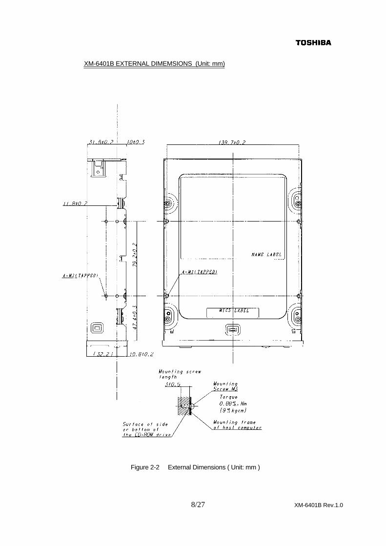
XM-6401B EXTERNAL DIMEMSIONS (Unit: mm)
Figure 2-2 External Dimensions ( Unit: mm )

9/27 XM-6401B Rev.1.0
3.5. Reliabilities
3.5.1. Error Rate(1) Hard Read Error Rate (Byte Error Rate) ----- Allowing 5 Retries -----
Mode 1: 10 -15 MaxMode 2: 10 -12 Max
(2) Seek Error Rate --- Allowing 5 Retries 10 -6 Max
3.5.2. MTBF 100,000 hAssumptions Power On Hours 5,436 h/year
On/Off Cycles 313 cycles/yearNumber of Access 600,000 accesses/yearOperating Duty Cycle 20 % of Power On Time
(Reading/Seeking)
3.5.3. MTTR 0.5 h
3.5.4. Drive Life 15,000 h or 5 years (earlier one)(1) Load/Eject 10,000 times or more(2) Interface connector Attach/Detach 20 times or more(3) DC Power connector Attach/Detach 20 times or more
4. ConfigurationSee Figure 3 for details of the configurations
4.1. Electrical Circuits(1) Optical Pickup and RF Amplifier Circuit(2) Motor Drive Circuit (3) EFM Demodulator and Error Correction Circuit
(System Control Circuit, Digital to Analog Converter)(4) SCSI Control and CD - ROM Error Correction Circuit and SCSI I/O Interface Circuit(5) System Control Circuit
4.2. Optical Pickup Semiconductor Laser and 3-beam System
4.3. Spindle Motor Brushless DC Motor
4.4. Feed Motor DC Motor
4.5. Load/Eject Motor DC Motor

10/27 XM-6401B Rev.1.0
DIS
C M
OT
OR
PU
HR
F A
MP
SE
RV
O A
MP
RA
M
VC
O
EF
MD
E. M
OD
.
EC
C
SE
RV
OC
ON
TR
OL
DA
C
VC
O C
ON
TR
OL
AU
DIO
EF
E.
D-O
UT
MO
D
CD
-RO
M S
YN
C.
DE
FE
CT
DE
SC
RA
MB
LE
MA
ST
ER
CL
OC
K G
EN
.
HP
AM
P SR
AM
MIC
RO
PR
OC
ES
SO
R
INT
CO
NT
RO
LT
IME
RT
IMIN
GC
ON
TR
OL
PE
RIP
HE
RA
L
INT
ER
FA
CE
AC
CE
SS
FE
ED
MO
TO
R
TR
AY
LO
AD
MO
TO
R D
RIV
ER
KZ
6376
F
33.8
6MH
z
Lin
e
OU
T
H.P
.
OU
T
LP
F
SCSI CONECTOR
CL
OC
KG
EN
ER
AT
ER
Co
mp
arat
or
(Hal
l ele
men
t)
Po
siti
on
Det
ecto
r
128k
x 1
6 b
it
64k
x 16
bit
FL
AS
H
VE
LO
CIT
YD
ET
EC
TO
RZ
80 C
OM
PA
TIB
LE
CO
NT
RO
L
-HT
-020
3P
XR
-540
G
Act
uat
or
DR
IVE
R
BA
5983
FP
TA
8493
AF
TC
9450
AF
BH
3543
F
2M D
RA
M
TA
2140
FN
DE
SC
RA
MB
LE
SC
SI C
on
tro
lE
CC
& E
DC
SU
B C
OD
ES
CS
I DR
BufferControl
LC
8951
27
Figure 3 Configuration

11/27 XM-6401B Rev.1.0
5.Function5.1. CD-ROM Data Configurations
Figure 4 shows how the data is structured in program units1 block=1/75 s
TimeTNO
TOC0 Lead-in
MinSecBlock
Block 1
MinSecBlock
1
Block 2
2approx.
300 k-
Blocks
~ ~ ~ ~AA Lead out
1-Disc
SYNC12 bytes
Header
User Data2048 bytes in Mode-12336 bytes in Mode-2
~ ~
~ ~
ECC(Mode-1)
288 bytes
Minutes
Second(0~59)
Blocks(0~74)
Mode
4 bytes
Figure 4 CD-ROM Data Configure
5.2. Power ON/OFF TimingFigure 5 shows the initialization sequence
Power ON or SCSI-RST
SystemInitialization
Focus Search
Spindle ON
Learning
Stand-by
"TEST UNIT READY" Command Correspondence
Max. 200 ms
Max. 2 s
Max. 5 s
Typ. 8 s, Max.12 s
(Single Session Disc)
"Command" Receivable
"Read-Command" Acceptable
No Reply
"Check Condition" Status "Good" Status
Figure 5 Initialization Sequence

12/27 XM-6401B Rev.1.0
6. Interface
(1) The interface is based on ANSI standard X3.131-1994 and X3T9.2/375R(2) 42 commands are usable including CD-ROM unique commands(3) The CD-ROM drive supports SCSI synchronous transfer and CD-DA data transfer
over SCSI function(4) The 256 KByte data buffer handles both high and low speed data transmission(5) The largest block size on playback is 2,647 Bytes (Including Error Flags)
The data length for each block is changeable by command(6) On command execution, DISCONNECT processing and RECONNECT processing
can be specified(7) Command Link functions are usable
6.1. Signal Lines
(1) Logical levels of every Inputs and Output are logically false signals
Input Low = 0.0 to +0.4 V=Logic '1' (true)
Input High = +2.5 V to +5.25 V=Logic '0' (false)
Output Low >/= 48 mA
Output High = Open collector (high impedance)
(2) The power supply line has a protection inside of the drive to protect the power supply.This is shown in Figure 6
SCSI Connector #26
Protector+5 V Diode 'POWER SUPPLY' header
Figure 6 Power Supply Line
6.1.1. Signal Line TerminationFigure 7 and Figure 8 shows the method for daisy chain connection and Figure 9 and Figure 10 shows the method for radial connection.Always connect the terminator for SCSI because of the open collector configurationoutput drive.Also be sure to attach the frame ground for grounding with the host system.
6.1.2. Receivers and DriversFigure 11 shows the construction and Figure 13 shows the interface pin assignments.
6.1.3. ConnectorFigure 12 shows the details of connector and Figure 13 shows the interface pin assignments.

13/27 XM-6401B Rev.1.0
7. Power Requirements
7.1. Source Voltage +5 V +/-5 % (operating)
+12 V +/-5 % (operating)
7.1.1. Spike 100 mV (p-p) Max
7.1.2. Ripple 100 mV (p-p) Max
7.2. Current Drain (Typical value) ---------- excluding 'Term Power' current ----------+5 V +12 V
7.2.1. Idle (Laser off, Motor off) 0.30 A 0.05A
7.2.2. Continuous Read (Data/Audio) 0.45 A (6-14X ) 0.19 A (6-14X )
7.2.3. Pause (Laser on, Motor on) 0.52 A (17.3-40X ) 0.22 A (17.3-40X )
7.2.4. Average (20 % Random Access) 0.60 A (17.3-40X ) 0.60 A (17.3-40X )
7.2.5. Maximum (100 % Random Access) 0.62 A (17.3-4.X ) 0.72 A (17.3-40X )
7.2.6. Peck in executing Access (10 to 300 ms) 1.35 A (17.3-40X ) 1.21 A (17.3-40X )

14/27 XM-6401B Rev.1.0
Terminator
Interface Card
Host System
Drive 1 Drive 2 Drive 3
Terminator
Frame Ground
Max. 7 units connectable (SCSI Bus)
Figure 7 Daisy Chain Connection--- Turn off Internal Terminators from the driveif XM-6401Bs are used as Drive 1 and/or Drive 2. ----
Terminator
Interface Card
Host System
Drive 1 Drive 2 Drive 3
Terminator
Frame Ground
Max. 7 units connectable (SCSI Bus)
Figure 8 Daisy Chain Connection--- Turn off Internal Terminators from the drive according -----

15/27 XM-6401B Rev.1.0
Terminator Terminator Terminator Terminator
Interface Card
Interface Card
Host System
Drive 1 Drive 2
Frame Ground
Figure 9 Radial Connection
Terminator Terminator
Terminator Terminator
Interface Card
Interface Card
Host System
Drive 1 Drive 2
Frame Ground
Figure 10 Radial Connection according ----- Turn off Internal Terminators from those drives ---

16/27 XM-6401B Rev.1.0
+5 V +5 V
7438 or equiv. 74LS240 or equiv.
110
OH
M
Controller
Ter
min
ator
CD-ROM Drive
Terminator ON/OFF
ActiveTerminator
+5 V +5 V
7438 or equiv.
110
OH
M
Terminator ON/OFF
ActiveTerminator T
erm
inat
or
ControllerCD-ROM Drive
74LS240 or equiv.
Figure 11 Receivers and Drivers

17/27 XM-6401B Rev.1.0
13.0
2.54
6.6
8.5
0.3
2.54
60.96
69.09
5.08
15.24
21.18
92.77
96.79
0.5 1.2
9.535
71.165 23.64
2
149
506.
6
Figure 12 Interface Connector

18/27 XM-6401B Rev.1.0
PIN No SIGNAL NAME PIN No SIGNAL NAME
2 -DB 0 1 GND
4 -DB 1 3 "
6 -DB 2 5 "
8 -DB 3 7 "
10 -DB 4 9 "
12 -DB 5 11 "
14 -DB 6 13 "
16 -DB 7 15 "
18 -DBP 17 "
20 GND 19 "
22 GND 21 "
24 GND 23 "
26 TERM POWER (+5 V) 25 NO CONNECTION
28 GND 27 GND
30 GND 29 "
32 -ATN 31 "
34 GND 33 "
36 -BSY 35 "
38 -ACK 37 "
40 -RST 39 "
42 -MSG 41 "
44 -SEL 43 "
46 -C / D 45 "
48 -REQ 47 "
50 -I / O 49 "
Figure 13 Interface Connector Pin Assignment

19/27 XM-6401B Rev.1.0
7.3. Connector (SCSI and Power Hybrid type)Figurer 14 shows the external appearance of the Power Supply Connector.Use IRISO ELECTRONICS P/N9047B-54Z12-GT or equivalent.
#1 #2 #3 #4
PIN #1: +5 V
PIN #2: GND
PIN #3: GND
PIN #4: +12 V
Figure 14 Power Supply Connector
8.Audio (Test condition:Ordinary temperature)----- Specification for Red Book Disc -----
Output : 2 channel (Analog Audio)Sampling Frequency : 44.1 kHzQuautization : 16 bit linear
8.1. Line Output --- in case of attenuator is set at 0 dB by the command ---(1) Output Level 0.75 V (rms Typ)(2) Type Unbalanced(3) Load Impedance 47 kOHM min(4) Frequency Response 20 Hz to 20 kH +/-3 dB(5) Distortion 0.014 % Typ (at 1 kHz with 20 kHz LPF)(6) Signal to Noise Ratio 83 dB Typ (IEC 179 A-weighted)
8.1.1.ConnectorFigure 15 shows, the external appearance of the 3P Audio Connector(Connector, Part No. 008283031100000, made by KYOCERA ELCO Corporation is used.Use matching housing, Part No. 608283303815000, made by KYOCERA ELCO Corporationor equivalent.)
#1 #2 #3
GND R LPIN #1: GND
PIN #2: R
PIN #3: L
Figure 15 Audio Connector

20/27 XM-6401B Rev.1.0
8.2. Headphones Output(1) Output Level 0.8 V (rms Typ)
(Attenuator Level is 0 dB)
(2) Level Adjust Controller Continuous Type (Thumb Wheel Knob)
(3) Load Impedance 100 OHM (Nominal)
8.2.1. Connector3.5 mm dia. Stereo Headphone Jack
8.3. Audio Modes
(1) 16 Modes including 'stereo', 'Rch Mono', and 'Mute' are selectable by command.Default mode is 'Stereo'. Audio out automatically muted in the digital area andseek state.
(2) 128 Steps of attenuation level for the Audio Output (both Line Out and HeadphonesOut together) is selectable by command.Default level is 0 dB.
9. Jumper Setting/Feature SelectionsSet up of SCSI-ID number, Parity Check function, Eject Button inhibit function and CD-AudioPlayback mode etc. are available by shorting these Headers.
ID 1 ID 2 ID 4 PRTY PRV/ALW TESTPOWERSUPPLY
TERMON/OFF
Figure 16 Mode Select Headers

21/27 XM-6401B Rev.1.0
9.1. SCSI-ID (ID 1, ID 2, ID4) (Default ID)This 3 bit binary header sets the SCSI-ID number.When setting numbers, follow the application software instructions.
Header LSB MSB
SCSI-ID ID 1 ID 2 ID 4
0 O O O
1 S O O
2 O S O
3 S S O
4 O O S
5 S O S
6 O S S
7 S S S
O: Open S: Short
9.2. Parity (PRTY)To enhance data bus reliability, set this Header to "S" to activate the parity bit check function onSCSI data bus.This setting cannot be used if no parity generation function is provided on the I/F card.
Header Description
O The drive does not check parity although the output parity is effective.
S The drive checks parity, and also the output parity is effective.
O: Open S: Short
9.3. Terminator Power ON/OFF (TERM ON/OFF)This Head setting turn on or turn off the terminator.
Header Description
O The terminator is turn off.
S The terminator is turn on.
O: Open S: Short

22/27 XM-6401B Rev.1.0
9.4. Media Eject Prevention (PRV/ALW)This Head setting enables or disables the eject function.
Header Description
O Allow the Tray eject.
SPrevent the Tray eject.Eject button is ignored.
O: Open S: Short
9.5. Audio Playback (TEST)This Header setting selects the drive operation between normal CD-ROM and CD-Audio playermode. When "S" is selected, command from the host computer is ignored.Also CD-Audio disc or audio tracks in CD-ROM disc is playable by the command when theHeader is set for "0".
Header Description
O Normal operation mode to connect the host computer.
S
(ID 1, ID 2, ID 4 and PRTY Headers should be set for O)CD-Audio disc playback mode. Allows repeated play from beginning of the program area up to the last when the disc is loaded. Pushing the Eject Button for shorter than1 s allows proceeding to beginning of the next track number but not acceptable duringaccess.Pushing the button more than 2 s stops playing and ejects the Tray.
O: Open S: Short
9.6. Power Supply (POWER SUPPLY)This header setting switches to supply the power (+5 V) to the other equipments throughthe SCSI connector or not.
Header Description
O No power is supplied from the drive.
S Power is supplied to the other peripherals through SCSI Connector (Pin No. 26).
O: Open S: Short
9.7. Jumper (Part Number T/E)Use P/N 9251H-GF made by IRISO Electronics or equivalent.
9.8. Recognition of SettingAs the setting recognition is performed only after power On, turn power off and thenOn again whenever change is made.

23/27 XM-6401B Rev.1.0
10. Busy IndicatorThe LED at Front Bezel (Busy Indicator) indicates the drive status.(1) After Drawer is closed, Busy Indicator start blinking at 0.8 s intervals, and then ----- (1-1) Turns off when the drive in the 'Idle' status.
0.8 s
Light Off
Figure 17 Idle(1-2) Continuously off when no disc is mounted.
0.8 s
Light Off
Figure 18 No disc
(1-3) Still blinking at 3.2 s intervals when cleaning for disc or optics in the drive is required.0.8 s 3.2 s
Figurer 19 Maintenance Required
(1-4) Continuously on when media has problem0.8 s
Light On
Figure 20 Media Problem
(2) When playing an audio track, Busy Indicator is blinking at 1.6 s intervals.1.6 s
Figurer 21 CD-Audio playback
(3) When performing 'Data Access' and during 'Data Transfer' Busy Indicator keeps turn On.
Light On
Figurer 22 Data Access and Data Transfer

24/27 XM-6401B Rev.1.0
11.Connection11.1. Power Supply Cable
(1) Housing AMP JAPAN P/N 1-480424-0 or equivalent(2) Contact AMP JAPAN P/N 170148-2 or equivalent(3) Cable Length AWG 18 to 20
Max. 2 m
11.2. Interface Cable(1) Connector SCSI specification(2) Cable 50 core type
Specific Impedance 100 OHM +/-10 % (without shield)Length Max of 6 m for total SCSI bus length
Max of 3 m for total SCSI bus length (FAST SCSI)Max of 1.5 m for total SCSI bus length (Ultra SCSI)
11.3. Audio Cable Unbalanced and shielded(1) Capacitance Less than 1000 pF(2) Length Max 3 m
12. MaintenanceIn case of Figure 19, cleaning for disc or optics in the drive is required.
12.1. DiscTry to avoid touching the read area (underside) of the disc as dirt and smear will degradethe disc accessing speed.If the disc dirty, wipe it with a soft cloth.
12.2. Optical PickupA dirty optical pickup will also degrade the access time.In such a care, please consult our company.
13.Emergency EjectExecute following procedure only in the case of emergency (Tray will not open although pressingEject button).(1) Turn the CD-ROM drive supplying power off, and then keep the this condition for 1 minute.(2) Insert solid bar (like paper clip) into Emergency eject hole and push as shown in Fig.23.
Then Tray will be ejected.
50 mm
diameter 1.0 - 1.5 mm
Figurer 23

25/27 XM-6401B Rev.1.0
14.Safety standards/Agency Approvals
(1) Safety EN60950UL 1950CAN/CSA-22.2 No.950
(2) Laser EN60825-1, FDA 21CFR(3) EMI FCC 15J - B(4) CE EN50081-1 : 1992 [Residential, commercial & light industry]
EN55022+A2 : 1994+1997 [Class B]EN55082-1 : 1997 [Residential, commercial & light industry]EN61000-4-2+A1 : 1995+1998 [CD:4 kV, ID: 4 kV, AD:8 kV]EN61000-4-3 : 1996 [3 V/m, 80-1000 MHz, 1 kHz 80 % AM ]ENV50204 : 1995 [3 V/m, 895-905 MHz,200 Hz 50 % PM ]EN61000-4-4 : 1995 [AC-line: 1 kV, Signal-line: 0.5 kV,
f: 5 kHz, Polarity: +/-]EN61000-4-5 : 1995 [AC-line: 1 kV/2 kV, Signal-line: 0.5 kV,
Polarity: +/-]EN61000-4-6 : 1996 [3 V, 0.15-80 MHz, 80 % AMEN61000-4-8 : 1993 [3 A/m, 50 Hz]EN61000-4-11 : 1994 [ 30 % 10 ms, 60 % 100 ms, >95 % 5 s]
15. Electrostatic Discharge
Standard EN61000-4-2(1) Operating Contact Discharge: 4 kV or less
Air Discharge : 8 kV or less
16. Accessories1-Safety Instruction Manual5-Short Jumper (Installed in 'TERM' header and GNDto GND)
17. Packaging15 units in a bulk package24 bulk packs on one pallet.
*All transportation is allowed with pallet.(Transportation is not allowed with bulk package.)
Standard packaging Specifications: IB-CD1-A80002
18. CE Declaration of conformityPlease refer to attached Annex 1.

26/27 XM-6401B Rev.1.0
TOSHIBA TOSHIBA EUROPE GMBH
EU-Declaration of Conformity
Product: CD-ROM Drive
Manufacturer(s): Toshiba Corporation1-1, Shibaura 1-chome, Minato-ku, Tokyo 105-8001 Japan
See page 2 for other locations
Model: XM-6401B
Options: None
Toshiba declares that the above mentioned product(s) with or withoutthe listed options comply to the EU-Directives and standards as listed on page 2.
Last two digits of the year in which the CE mark affixed : 98
Responsible for CE-marking: Toshiba Europe GmbH
Signed by: Mr. H.Nonaka, President of Toshiba Europe GmbH
Place: D-41460 Neuss
Date:
Signature: ----------------------------------------------------------
This declaration certifies compliance with the listed directives, but does not constitute anassurance of characteristics.The safety information in the supplied product documentation must be observed.............................................................................................................................................................Document No.: YEA-T345 Page: 1 of 2............................................................................................................................................................[History if issue] Issued : Oct. 20, 1998
...................................................Revision A : Ref.:................................................... .........................Revision B : Ref.:................................................... .........................Revision C : Ref.:................................................... .........................Revision D : Ref.:................................................... .........................
TOSHIBA EUPOPE GMBH
HAMMFELODAMMB.D-41460NEUSS GESCHAFTSUHRER
POSTFCH 101482. D-41414 NEUSS HISATSUGU NONAKA
TELEFON: (02131) 158-01 HRB 3479 AMTSGERICHT NESS
TELFAX : (02131) 158-341
Annex 1

27/27 XM-6401B Rev.1.0
EU
-Dec
lara
tio
n o
f C
on
form
ity
ED
-Dir
ecti
veR
elat
ed S
tan
dar
dIs
sud
eL
evel
/Tes
t co
nd
itio
n
EM
C-e
mis
sion
:
EM
C-im
mun
ity
Pro
du
ct/O
pti
on
sM
od
elR
elat
ed E
U-D
irec
tive
89/3
36/E
EC
CD
-RO
M D
rive
XM
-640
1BX
Man
ufac
tuer
(s)
Loca
tion
Add
ress
Pag
e:
Rev
isio
n:
EN
5502
2+A
2
1994
+19
97
C
lass
B
E
N50
081-
1
19
92
Res
iden
tial,
com
mer
cial
& li
ght i
ndus
try
EN
5008
2-1
1997
R
esid
entia
l, co
mm
erci
al &
ligh
t ind
ustr
yE
N61
000-
4-2+
A1
199
5+19
98
C
D: 4
kV
, ID
: 4 k
V, A
D: 8
kV
EN
6100
0-4-
3
1996
3
V/m
, 80-
1000
MH
z, 1
kH
z 80
% A
M
E
NV
5020
4
1
995
3
V/m
, 895
-905
MH
z, 2
00 H
z 50
% P
M
E
N61
000-
4-4
19
95
AC
-line
: 1 k
V, S
igna
l-lin
e: 0
.5 k
V,
f: 5
kHz,
Pol
arity
: +/-
EN
6100
0-4-
6
1996
3
V, 0
.15-
80 M
Hz,
80
% A
M
EN
6100
0-4-
8
1993
3
A/m
, 50
Hz
E
N61
000-
4-11
199
4
30 %
10
ms,
60
% 1
00 m
s, >
95 %
5 s
ec
Tos
hiba
Mul
ti M
edia
Dev
ices
Co,
Ltd
.
1
9 M
inas
e, F
ukih
ata
Gos
hoga
war
a-sh
i, A
omor
i 037
-000
3 Ja
pan
Tos
hiba
Mis
awa
Med
ia D
evic
es C
o, L
td.
3-
31-2
779,
Min
ami-c
ho, M
isaw
a-sh
i, A
omor
i-ken
033
-003
6 Ja
pan
EM
S C
orp.
4-
5 S
houb
u, U
baya
chi G
osho
gaw
ara-
shi,
Aom
ori 0
37-0
015
Japa
nH
okut
o C
omm
unic
atio
n In
dust
rial C
o., L
td.
2
07 A
za K
oam
on, R
okug
o, R
okug
o-m
achi
, Sen
boku
-gun
, Aki
ta 0
19-1
404
Japa
nY
uzaw
a D
ensh
i Kog
yo C
o., L
td.
2
57 N
akan
o Y
uzaw
a-sh
i, A
kita
012
-004
1 Ja
pan
YE
A-T
345
Do
cum
ent
No
.:
2 o
f 2
899/
336/
EE
C(E
MC
Dire
ctiv
e)
EN
6100
0-4-
5
1995
A
C-li
ne: 1
kV
/2 k
V, S
igna
l-lin
e: 0
.5 k
V,
f: 5
kHz,
Pol
arity
: +/-
Tos
hiba
Info
rmat
ion
Equ
ipm
ent (
Phi
lippi
nes)
Inc.
10
3 E
ast M
ain
Ave
nue
Ext
ensi
on, S
peci
al E
xpor
t Pro
cess
ing
Zon
e,
Lagu
na T
echn
opar
k, B
inan
, Lag
una
Phi
lippi
nes
Inte
grat
ed M
icro
elec
tron
ic In
c.
Nor
th S
cien
ce A
venu
e La
guna
Tec
hno
Par
k In
c. B
inan
, Lag
una
Phi
lippi
nes
Alp
ine
Tec
hnol
ogy
Man
ufac
turin
g In
c.
6
1-1
Shi
nbor
i, O
hara
, Ona
ham
a, Iw
aki-s
hi, F
ukus
him
a, 9
71-8
111
Japa
n
Toh
oku
TK
R C
orpo
ratio
n
2-10
6 K
itaoy
amad
a, T
owac
ho, W
aga-
gun,
Aom
ori,
028-
0107
Jap
an