XLR8 Mechanical Splice Fiber Connector...
6
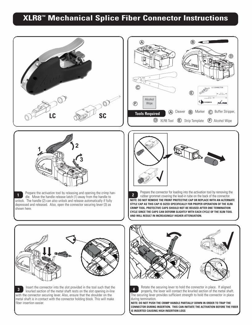
XLR8 ™ Mechanical Splice Fiber Connector Instructions Prepare the connector for loading into the activation tool by removing the rubber grommet covering the lead-in tube on the back of the connector. NOTE: DO NOT REMOVE THE FRONT PROTECTIVE CAP OR REPLACE WITH AN ALTERNATE STYLE CAP AS THIS CAP IS SIZED SPECIFICALLY FOR PROPER OPERATION OF THE XLR8 CRIMP TOOL. PROTECTIVE CAPS SHOULD NOT BE REUSED AFTER ONE TERMINATION CYCLE SINCE THE CAPS CAN DEFORM SLIGHTLY WITH EACH CYCLE OF THE XLR8 TOOL AND WILL RESULT IN INCREASINGLY HIGHER ATTENUATION. 2 1 2 3 Prepare the activation tool by releasing and opening the crimp han- dle. Move the handle release latch (1) away from the handle to unlock. The handle (2) can also unlock and release automatically if fully depressed and released. Also, open the connector securing lever (3) as shown here. 1 Rotate the securing lever to hold the connector in place. If aligned properly, the lever will contact the knurled section of the metal shaft. The securing lever provides sufficient strength to hold the connector in place during termination. NOTE: DO NOT PUSH THE CRIMP HANDLE PARTIALLY DOWN IN ORDER TO TRAP THE CONNECTOR DURING INSERTION. THIS CAN INITIATE THE ACTIVATION BEFORE THE FIBER IS INSERTED CAUSING HIGH INSERTION LOSS 4 Insert the connector into the slot provided in the tool such that the knurled section of the metal shaft rests on the slot opening in-line with the connector securing lever. Also, ensure that the shoulder on the metal shaft is in contact with the connector holding block. This will make fiber insertion easier. 3 LC SC Tools Required 29 mm STRIP LENGTH 39 mm CONN REF LINE LC CONNECTOR Alcohol Wipe Cleaver Marker Buffer Stripper, XLR8 Tool Strip Template Alcohol Wipe
Transcript of XLR8 Mechanical Splice Fiber Connector...
XLR8™ Mechanical Splice Fiber Connector Instructions
Prepare the connector for loading into the activation tool by removing therubber grommet covering the lead-in tube on the back of the connector.
NOTE: DO NOT REMOVE THE FRONT PROTECTIVE CAP OR REPLACE WITH AN ALTERNATESTYLE CAP AS THIS CAP IS SIZED SPECIFICALLY FOR PROPER OPERATION OF THE XLR8CRIMP TOOL. PROTECTIVE CAPS SHOULD NOT BE REUSED AFTER ONE TERMINATIONCYCLE SINCE THE CAPS CAN DEFORM SLIGHTLY WITH EACH CYCLE OF THE XLR8 TOOLAND WILL RESULT IN INCREASINGLY HIGHER ATTENUATION.
2
12
3
Prepare the activation tool by releasing and opening the crimp han-dle. Move the handle release latch (1) away from the handle to
unlock. The handle (2) can also unlock and release automatically if fullydepressed and released. Also, open the connector securing lever (3) asshown here.
1
Rotate the securing lever to hold the connector in place. If alignedproperly, the lever will contact the knurled section of the metal shaft.
The securing lever provides sufficient strength to hold the connector in placeduring termination. NOTE: DO NOT PUSH THE CRIMP HANDLE PARTIALLY DOWN IN ORDER TO TRAP THE CONNECTOR DURING INSERTION. THIS CAN INITIATE THE ACTIVATION BEFORE THE FIBERIS INSERTED CAUSING HIGH INSERTION LOSS
4Insert the connector into the slot provided in the tool such that theknurled section of the metal shaft rests on the slot opening in-line
with the connector securing lever. Also, ensure that the shoulder on themetal shaft is in contact with the connector holding block. This will makefiber insertion easier.
3
LC SC Tools Required �
�
�
�
�
�
�
�
�
�
29 mmSTRIP LENGTH
39 mmCONN REF LINE
LC CONNECTOR
AlcoholWipe
��
Cleaver Marker Buffer Stripper,
XLR8 Tool Strip Template Alcohol Wipe
INS_17881.00_E_New_XLR8_E 3/31/11 3:08 PM Page 1
XLR8™ Mechanical Splice Fiber Connector Instructions
Remove the section of buffer coating up to the first mark using a bufferstripper. To avoid breaking the fiber, remove the buffer in several small
sections. Carefully inspect each fiber after stripping to verify the buffer coating isalso removed. Sometimes mistaken to be the fiber cladding, this coating must becompletely removed or the fiber will not fit into the connector.
7Install the boot by sliding the narrow end first down the fiber until itis out of the way6
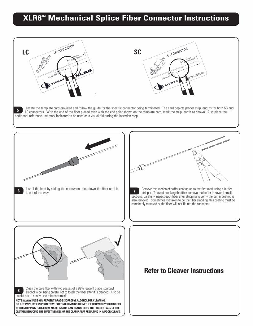
Locate the template card provided and follow the guide for the specific connector being terminated. The card depicts proper strip lengths for both SC andLC connectors. With the end of the fiber placed even with the end point shown on the template card, mark the strip length as shown. Also place the
additional reference line mark indicated to be used as a visual aid during the insertion step. 5
29 mm
STRIP LENGTH
39 mm
CONN REF LINE
LC CONNECTOR
LC26 mm
STRIP LENGTH
36 mm
CONN REF LINE
SC CONNECTOR
P/N:100.17882.00
SC
Clean the bare fiber with two passes of a 99% reagent grade isopropyl alcohol wipe, being careful not to touch the fiber after it is cleaned. Also be
careful not to remove the reference mark.NOTE: ALWAYS USE 99% REAGENT GRADE ISOPROPYL ALCOHOL FOR CLEANING.DO NOT WIPE EXCESS PROTECTIVE COATING REMAINS FROM THE FIBER WITH YOUR FINGERSAFTER STRIPPING. OILS FROM YOUR FINGERS CAN TRANSFER TO THE RUBBER PADS OF THECLEAVER REDUCING THE EFFECTIVENESS OF THE CLAMP ARM RESULTING IN A POOR CLEAVE.
8
Refer to Cleaver Instructions
INS_17881.00_E_New_XLR8_E 3/31/11 3:08 PM Page 2
Remove the freshly cleaved fiber without contaminating the end face. The fiber is now ready for insertion into the connector.NOTE: IT IS NOT NECESSARY OR RECOMMENDED TO RE-WIPE THE FIBER AFTER CLEAVING AS THIS PRACTICE COULD LEAVE DEBRIS ON THE END-FACE WHERE IT IS
DIFFICULT TO CLEAN PRECISELY. IF A MIS-CLEAVE OCCURS, STRIP THE BUFFER BACK FURTHER AND CLEAVE IN A DIFFERENT LOCATION. DO NOT TRY TO RE-CLEAVE IN THE SAMELOCATION ON THE FIBER.
9
XLR8™ Mechanical Splice Fiber Connector Instructions
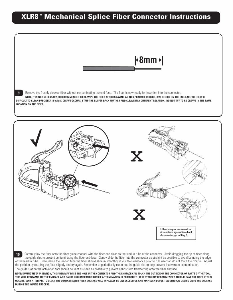
8mm
Carefully lay the fiber onto the fiber guide channel with the fiber end close to the lead-in tube of the connector. Avoid dragging the tip of fiber alongthe guide slot to prevent contaminating the fiber end-face. Gently slide the fiber into the connector as straight as possible to avoid bumping the edge
of the lead-in tube. Once inside the lead-in tube the fiber should slide in smoothly, if you feel resistance prior to full insertion do not force the fiber in. Adjustthe position by rotating the fiber slightly and try again. Remember to periodically clean out the guide slot to help prevent inadvertent contamination.The guide slot on the activation tool should be kept as clean as possible to prevent debris from transferring onto the fiber endface.NOTE: DURING FIBER INSERTION, THE FIBER MAY MISS THE HOLE IN THE CONNECTOR AND THE ENDFACE CAN TOUCH THE OUTSIDE OF THE CONNECTOR OR PARTS OF THE TOOL.THIS WILL CONTAMINATE THE ENDFACE AND CAUSE HIGH INSERTION LOSS IF A TERMINATION IS PERFORMED. IT IS STRONGLY RECOMMENDED TO RE-CLEAVE THE FIBER IF THISOCCURS. ANY ATTEMPTS TO CLEAN THE CONTAMINATED FIBER ENDFACE WILL TYPICALLY BE UNSUCCESSFUL AND MAY EVEN DEPOSIT ADDITIONAL DEBRIS ONTO THE ENDFACEDURING THE WIPING PROCESS.
10
If fiber scrapes in channel orhits endface against tool/backof connector, go to Step 5.
x
x
INS_17881.00_E_New_XLR8_E 3/31/11 3:08 PM Page 3

XLR8™ Mechanical Splice Fiber Connector Instructions
Opening the connector securing lever.14
While maintaining inward pressure, depress the tool handle as far asit will go to crimp the fiber into place and complete the termination..
NOTE: DO NOT CONTACT THE BOWED FIBER WHILE DEPRESSING THE CRIMP HANDLEAS IT CAN CAUSE THE FIBER TO MOVE INSIDE THE CONNETOR BEFORE THE TERMINATION IS COMPLETE RESULTING IN HIGH INSERTION LOSS.
13
Slide the boot up to the back of the connector and gently press ontoplace while holding the connector housing.
NOTE: NEVER PULL ON THE FIBER TO ENGAGE THE BOOT OR WHILE HANDLING THETERMINATED CONNECTOR AS THIS CAN CAUSE A GAP AT THE SPLICE JOINT RESULTING IN EXCESSIVE INSERTION LOSS.
16
Remove the connector by lifting the connector straight up and out ofthe tool.15
Use the reference line mark on the buffer to verify the fiber is fullyinserted. Once you feel the fiber firmly stop against the internal fiber
stub, check the location of the reference line mark. If fully inserted and measured correctly, the mark should be visible just before the entrance ofthe lead-in tube.
11
25.4mm(1 in.)
Hold the fiber securely into the connector by placing gentle but consistent inward pressure – enough to form a slight bow
– approximately 25.4mm (1.0 in.) – in the fiber.12
1. 2.
INS_17881.00_E_New_XLR8_E 3/31/11 3:08 PM Page 4
XLR8™ Mechanical Splice Fiber Connector Instructions
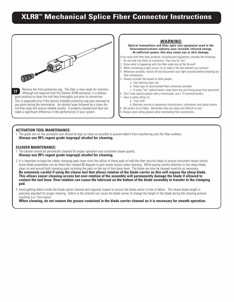
Remove the front protective cap. The fiber is now ready for insertion.Although not required with the Siemon XLR8 connector, it is always
good practice to clean the end face thoroughly just prior to connection. This is especially true if the factory installed protective cap was removed atany point during the termination. An alcohol wipe followed by a clean drylint-free wipe will ensure reliable results. A properly cleaned end face canmake a significant difference in the performance of your system.
17
ACTIVATION TOOL MAINTENANCE:1. The guide slot on the activation tool should be kept as clean as possible to prevent debris from transferring onto the fiber endface.
Always use 99% regent grade isopropyl alcohol for cleaning.
CLEAVER MAINTENANCE:1. The cleaver should be periodically cleaned for proper operation and consistent cleave quality.
Always use 99% regent grade isopropyl alcohol for cleaning.2. It is important to keep the rubber clamping pads clean since the ability of these pads to hold the fiber security helps to ensure consistent cleave results.
Some blade assemblies can be lifted then rotated 90 degrees to gain easier access when cleaning. While paying careful attention to the sharp blade,clean on and around both clamping pads including the pads on the top of the clamp lever. The blade can also be cleaned carefully as necessary. Be extremely careful if using the cleave tool that allows rotation of the blade carrier as this will expose the sharp blade. This allows easier cleaning access but over-rotation of the assembly will permanently damage the blade if allowed to contact the tool base. Over-rotation can cause the lubricant on the bottom of the blade assembly to transfer to the clampingpad.
3. Avoid getting debris inside the blade carrier channel and regularly inspect to ensure the blade carrier is free of debris. The cleave blade height is precisely adjusted for proper cleaving. Debris in the channel can cause the blade carrier to change the height of the blade during the cleaving processresulting in a “mis-cleave”.When cleaning, do not remove the grease contained in the blade carrier channel as it is necessary for smooth operation.
WARNING:Optical transmitters and fiber optic test equipment used in the
telecommunications industry uses invisible infrared energy.At sufficient power, this may cause eye or skin damage.
If you work with fiber optic products, including test equipment, consider the following:1. Do not look into fibers or connectors. They may be ‘live’.2. Know what is happening with the fiber under test at the far end!3. When connecting a light source, try to make it the last element you connect!4. Whenever possible, switch off and disconnect your light source(s) before breaking any
fiber connections.5. Always consider the hazard to other people:
a. Use warning signs, etc.b. Keep caps on unconnected fibers whenever possible.c. If using “live” optical beams, keep them low and facing away from personnel.
6. Don’t view optical outputs with a microscope, use a TV camera/monitor.7. Elect a safety officer to:
a. Train staffb. Maintain records of equipment classification, calibrations and safety checks.
8. Be careful of cut fibers. Remember they are sharp and difficult to see!9. Always wear safety glasses when terminating fiber connections.
INS_17881.00_E_New_XLR8_E 3/31/11 3:08 PM Page 5

Rev
. F
04
/11
10
0.1
78
81.0
0©
201
1 T
he S
iem
on C
ompa
ny
www.siemon.com
Global HeadquartersWatertown, Connecticut USA
Tel: (1) 866-548-5814
For a complete listing of our global offices visit our web site:www.siemon.com
INS_17881.00_E_New_XLR8_E 3/31/11 3:08 PM Page 6