XK09-DLPKHO EN IG PGa20120221 - ... · PDF file2012 2011 2010 2009 2008 2007 2006 2005 2004...
19
Underside of XK09 module Vehicle Application Guide... Type 1. Installation ......................................................................................................................................... ........................................................................................................................................................................ Type 2......................................................................................................................................................................... Type 3 - D2D............................................................................................................................................................... Type 3 - W2W.............................................................................................................................................................. Type 4......................................................................................................................................................................... Type 5......................................................................................................................................................................... Type 6......................................................................................................................................................................... Locating Components in the Acura TL (Type 6).......................................................................................................... Type 7......................................................................................................................................................................... Locating Components in the Acura ZDX (Type 7)....................................................................................................... Type 8......................................................................................................................................................................... Type 9......................................................................................................................................................................... Module Programming.................................................................................................................................................. Resetting the Module.................................................................................................................................................. LED Diagnostics & Troubleshooting............................................................................................................................ Programming Vehicle Wiring Reference Charts................................................................................................................................ Limited One-Year Consumer Warranty ........................................................................................................................ 02 03 04 05 06 07 08 09 10 11 12 13 14 15 16 17 18 19 Index † Acura and Honda are registered trademarks and property of their respective companies. Installation Guide Update Alert: Firmware updates are posted to the web on a regular basis. We recommend that you check for firmware and/or install guide updates prior to installing this product. The XK09-DLPKHO is a door lock with bypass or bypass only module that interfaces directly with Honda and Acura to provide features compatible with sliding doors, motorized trunks/hatches, and XK09 DLPKGM LOT.168 H.2.S.x 0TT000001 1243000960230 10E XK09 MADE IN CANADA Important! This firmware is compatible with the following hardware version: H.2. ONLY H.2.S.x Rev.: 20120221 Platform: XK09 Firmware: DLPKHO The Mobile Integration Systems © 2012 Directed. All rights reserved.
-
Upload
hoangkhanh -
Category
Documents
-
view
214 -
download
2
Transcript of XK09-DLPKHO EN IG PGa20120221 - ... · PDF file2012 2011 2010 2009 2008 2007 2006 2005 2004...

Underside of XK09 module
Vehicle Application Guide...
Type 1.Installation
.........................................................................................................................................
........................................................................................................................................................................Type 2.........................................................................................................................................................................Type 3 - D2D...............................................................................................................................................................Type 3 - W2W..............................................................................................................................................................Type 4.........................................................................................................................................................................Type 5.........................................................................................................................................................................Type 6.........................................................................................................................................................................Locating Components in the Acura TL (Type 6)..........................................................................................................Type 7.........................................................................................................................................................................Locating Components in the Acura ZDX (Type 7).......................................................................................................Type 8.........................................................................................................................................................................Type 9.........................................................................................................................................................................
Module Programming..................................................................................................................................................Resetting the Module..................................................................................................................................................
LED Diagnostics & Troubleshooting............................................................................................................................
Programming
Vehicle Wiring Reference Charts................................................................................................................................
Limited One-Year Consumer Warranty........................................................................................................................
02
030405060708091011121314
15
1617
18
19
Index
† Acura and Honda are registered trademarks and property of their respective companies.
Installation Guide
Update Alert: Firmware updates are posted to the web on a regular basis. We recommend
that you check for firmware and/or install guide updates prior to installing this product.
The XK09-DLPKHO is a door lock with bypass or bypass only module that interfaces directly withHonda and Acura to provide features compatible with sliding doors, motorized trunks/hatches, and
XK09DLPKGM
LOT.168 H.2.S.x
0T
T0
00
00
11
24
30
00
96
02
301
0E
XK
09
MA
DE
INC
AN
AD
A
Important!This firmware is compatible with the following hardware version: H.2.ONLY
H.2.S.x
Rev.: 20120221
Platform: XK09Firmware: DLPKHO
The Mobile Integration Systems
© 2012 Directed. All rights reserved.
Vehicle Application GuidePage 2
The doors are locked upon remote start on every type, with the exception of type 5, which does not control door locks.
Vehicles
2012
2011
2010
2009
2008
2007
2006
2005
2004
2003
2002
2001
DL-A
rmF
acto
ryS
ecurity
DL-D
isarm
Facto
ry
Security
DL-D
oor
Lock
Contr
ol
DL-D
oor
Unlo
ck
DL-D
river
Priority
Unlo
ck*
DL-H
atc
hG
lass
Rele
ase
DL-S
lidin
gD
oor
Contr
ol
Driver
DL-S
lidin
gD
oor
Contr
ol
Passenger
DL-T
runk
/H
atc
hR
ele
ase*
FO
B-C
ontr
olo
fafterm
ark
et
ala
rmw
ithO
EM
rem
ote
KI-
Push
To
Sta
rtIg
nS
w
Inte
rface
PK
-Im
mobilizer
Bypass-
Data
No
Key
Req'd
RS
-Tach
/R
PM
Outp
ut
SS
-Entr
yM
onito
ring
ALL
Door
Pin
s
SS
-Entr
yM
onito
ring
Driver
Door
Pin
SS
-Entr
yM
onito
ring
Hood
Pin
SS
-Entr
yM
onito
ring
Tru
nk/H
atc
hP
in
ST
-Bra
ke
Sta
tus
(foot
bra
ke)
ST
-Hand
Bra
ke
Sta
tus
ST
-Igniti
on
Sta
tus
ST
-Keysense
Sta
tus
Acura
CSX 3 3 3 3 3 D D D D D • D • • • D •** • D • D D
EL 5 5 5 5 5 •
MDX 2 2 2 2 2 • • • • • • D • • • D • • D • D D
MDX 5 5 5 5 •
RDX 3 3 3 3 3 D D D D D • D • • • D •** • D • D D
RSX 5 5 5 5 5 •
TL 4 4 4 4 1 1 1 1 1 • • • • • • D • • • D • • D • D D
TL (Smart Key) 6 6 6 6 • • • • • • D • • • • D • • • D D D
TSX 4 4 4 1 1 1 1 1 • • • • • • D • • • D • • D • D D
ZDX 4 • • • • • • D • • • D • • D • D D
ZDX (Smart Key) 7 7 • • • • • • D • • • • D • • • D D D
Honda 12 11 10 09 08 07 06 05 04 03 02 01
Accord 4 4 4 4 1 1 1 1 1 • • • • • • D • • • D • • D • D D
Accord Crosstour 4 4 • • • • • • D • • • D • • D • D D
Accord Hybrid 1 1 1 • • • • • • D • • • D • • D • D D
Civic 9 • • • • • D • • • D • • D • D D
Civic 3 3 3 3 3 3 D D D D D • D • • • D •** • D • D D
Civic 5 5 5 5 5 •
Civic Hybrid 3 3 3 3 3 D D D D D • D • • • D •** • D • D D
CRV 3 3 3 3 3 D D D D D • D • • • D •** • D • D D
CRV 5 5 5 5 5 •
Element 5 5 5 5 5 5 5 5 •
Fit 3 3 3 D D D D D D • • • D •** • D • D D
Fit 5 5 •
Insight 3 D D D D D • D • • • D •** • D • D D
Odyssey 8 1 1 1 1 1 1 • • • • • •* •* • D • • • D •** • D • D D
Pilot 4 4 4 • • • • • • • D • • • D • • D • D D
Pilot 5 5 5 5 •
Ridgeline 1 1 1 1 1 1 • • • • • D • • • D • • D • D D
Legend:
D: Data-to-Data (D2D) only DL: OE Door Lock & Alarm Controls KI: Ignition Key Sw itch Interface RS: Engine Start & Status ST: Function/Feature Status
W: Wire-to-Wire (W2W) only FOB: Sync CAN Interface w /FOB Remote PK: Transponder & Immobilizer Override SS: Integrated Security & Monitoring
•: W2W & D2D
* This feature will not work when the ignition is turned ON using the key or remote starter.
** This feature is only supported if the vehicle is equipped with an OEM alarm.
Rev.: 20120221
Platform: XK09Firmware: DLPKHO
The Mobile Integration Systems
© 2012 Directed. All rights reserved.

Installation Type 1(See the Vehicle Application Guide on page 2 to determine the installation type.)
Page 3
** The trunk will not open when the ignition is turned ON using the key or remote starter.
* The Tach wire is an optional connection required on some remote starters not supporting tach signal in D2D.
Not required in D2D mode.
Pin 5, Blue/Orange (orange on the Acura TSX)
Pin 2, Red/Blue (red on the Acura TSX)
Pin 1, Brown/Yellow
4
2
4
Programming Button
XK
09
(-) Neutral Safety (DEI Platforms Only)
(+) Accessory
(+) Ignition
(+) Start
Parking Lights
(+) 12 V Input
1: Red/Blue: Data Bypass
2: -
3: -
4: -
3: Gray: (-) Handbrake Sense Output
4: -
2: Green: (-) Door & Trunk Sense Output
1: Violet/White: (AC) Tach Output*
Rem
ote
Sta
rter
9: Red: (+) 12 V Input
10: Black: Ground Input
15: Yellow: Security Light (ECM side)
14: White: Data Bypass
12: Yellow/Black: Ground13: Violet/Brown: (-) Hood Output
17: Orange: Security Light (KEY side)
18: Green: Single Wire CAN
6: Red/White: (-) Trunk Input**
5: Blue: (-) Unlock Input
3: Light Green: (-) Lock Input
4: White/Violet: Aux 1 Passenger Slide Door Input
1: Blue/White: (-) GWR (status) Input
2: Violet/Black: Aux 2 Driver Slide Door Input
(-) Hood Input
(-) Aux 2 Driver Slide Door Output
(-) GWR (status) Output
(-) Lock Output
(-) Aux 1 Passenger Slide Door Output
(-) Unlock Output
(-) Trunk Output**
20
(-) Handbrake Status Input
(-) Door & Trunk Sense Input
(AC) Tach Input*
(-) Ground
+12VDC
1 2 3 4 5 6 7 8 9
10 11 12 13 14 18 19 20 2115 16 17
Fuse/Relay BoxKick panel driver side
4
(+) 12v
RX
(-) Ground
TX
(+) 12v
RX
(-) Ground
TX
XKD2D65
1 435 72 5 6
Key side
Ignition switch7-pin transponderconnector
Rev.: 20120221
Platform: XK09Firmware: DLPKHO
The Mobile Integration Systems
© 2012 Directed. All rights reserved.

1 435 72 5 6
Installation Type 2(See the Vehicle Application Guide on page 2 to determine the installation type.)
Page 4
4
42
4
Programming Button
XK
09
9: Red: (+) 12 V Input
10: Black: Ground Input
14: White: Data Bypass
13: Violet/Brown: (-) Hood Output
18: Green: Single Wire CAN
6: Red/White: (-) Trunk Input**
5: Blue: (-) Unlock Input
3: Light Green: (-) Lock Input
1: Blue/White: (-) GWR (status) Input20
Pin 4, Lt. Green
Pin 3, Lt. Green
Pin 7, Brown
Key side
1: Red/Blue: Data Bypass
2: -
3: -
4: -
Rem
ote
Sta
rter
3: Gray: (-) Handbrake Sense Output
4: -
2: Green: (-) Door & Trunk Sense Output
1: Violet/White: (AC) Tach Output*
(-) Handbrake Status Input
(-) Door & Trunk Sense Input
(AC) Tach Input*
(-) Ground
12: Yellow/Black: Ground
(-) GWR (status) Output
(-) Lock Output
(-) Unlock Output
(-) Trunk Output**
(-) Hood Input
(-) Neutral Safety (DEI Platforms Only)
(+) Accessory
(+) Ignition
(+) Start
(+) 12 V Input
** The trunk will not open when the ignition is turned ON using the key or remote starter.
* The Tach wire is an optional connection required on some remote starters not supporting tach signal in D2D.
Not required in D2D mode.
+12VDC
*** Connect the Rearm wire only if the vehicle is equipped with automatic headlights.
Rearm (Autolight Off)***
(-) Parking Lights(-) Parking Lights (at Light Switch)
(+) 12v
RX
(-) Ground
TX
(+) 12v
RX
(-) Ground
TX
XKD2D65
Ignition switch7-pin transponderconnector
Rev.: 20120221
Platform: XK09Firmware: DLPKHO
The Mobile Integration Systems
© 2012 Directed. All rights reserved.
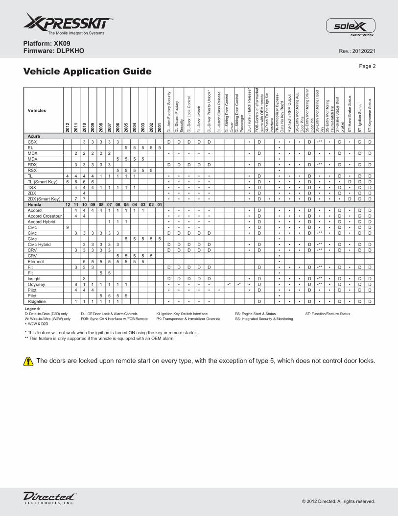
Installation Type 3 - D2D(See the Vehicle Application Guide on page 2 to determine the installation type.)
Page 5
Refer to the Vehicle Wiring Reference Chart on page 15.
Connect to Driver-Side Kick Panel.See Vehicle Wiring Reference
Chart on page 15.
4
42
4
Programming Button
XK
09
20
Key side
1: Red/Blue: Data Bypass
2: -
3: -
4: -
Rem
ote
Sta
rter
3: Gray: (-) Handbrake Sense Output
4: -
2: Green: (-) OutputLock
1: Violet/White: (AC) Tach Output
(-) Ground
(-) Neutral Safety (DEI Platforms Only)
(+) Accessory
(+) Ignition
(+) Start
Parking Lights
(+) 12 V Input
(-) Handbrake Status Input
(AC) Tach Input
Connect if not supported by the remote starter in D2D mode.
14: White: Data Bypass
13: Violet/Brown: (-) Unlock Output
18: Green: Single Wire CAN
12: Yellow/Black: Ground
* Trunk is only supported if the vehicle has a trunk function on the remote. It is also important to note that this function will not work when the engine isrunning.
(+) 12v
RX
(-) Ground
TX
(+) 12v
RX
(-) Ground
TX
XKD2D65
Pin 4, Pink (Lt. Green on Fit and Insight)
Pin 3, Lt. Green (Green on Fit and Insight)
Pin 7, Brown (Black on Civic)
Ignition switch7-pin transponderconnector
1 435 72 5 6
Rev.: 20120221
Platform: XK09Firmware: DLPKHO
The Mobile Integration Systems
© 2012 Directed. All rights reserved.
1 435 72 5 6
(-) GWR (status) Output
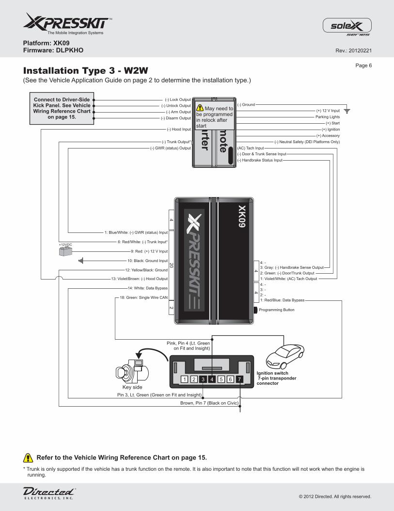
Installation Type 3 - W2W(See the Vehicle Application Guide on page 2 to determine the installation type.)
Page 6
Refer to the Vehicle Wiring Reference Chart on page 15.
4
42
4
Programming Button
XK
09
9: Red: (+) 12 V Input
10: Black: Ground Input
14: White: Data Bypass
13: Violet/Brown: (-) Hood Output
18: Green: Single Wire CAN
6: Red/White: (-) Trunk Input*
1: Blue/White: (-) GWR (status) Input
20
Key side
1: Red/Blue: Data Bypass
2: -
3: -
4: -
Rem
ote
Sta
rter
3: Gray: (-) Handbrake Sense Output
4: -
2: Green: (-) OutputDoor/Trunk
1: Violet/White: (AC) Tach Output
(-) Handbrake Status Input
(AC) Tach Input
(-) Ground
(-) Trunk Output*
12: Yellow/Black: Ground
(-) Disarm Output
(-) Hood Input
(-) Arm Output
(-) Unlock Output
(-) Lock Output
(-) Neutral Safety (DEI Platforms Only)
(+) Accessory
(+) Ignition
(+) Start
Parking Lights
(+) 12 V Input
(-) Door & Trunk Sense Input
+12VDC
Connect to Driver-SideKick Panel. See VehicleWiring Reference Chart
on page 15.
* Trunk is only supported if the vehicle has a trunk function on the remote. It is also important to note that this function will not work when the engine isrunning.
May need tobe programmedin relock afterstart
Pink, Pin 4 (Lt. Greenon Fit and Insight)
Pin 3, Lt. Green (Green on Fit and Insight)
Brown, Pin 7 (Black on Civic)
Ignition switch7-pin transponderconnector
Rev.: 20120221
Platform: XK09Firmware: DLPKHO
The Mobile Integration Systems
© 2012 Directed. All rights reserved.

Pin 4, Blue(Light Green for Honda Pilot) Pin 5, Pink
(White for Honda Pilot)
Pin 2, Light Green(Pink for Honda Pilot)
(-) Hood Input
Installation Type 4(See the Vehicle Application Guide on page 2 to determine the installation type.)
Page 7
** Connect the Rearm wire only if the vehicle is equipped with automatic headlights.* The Tach wire is an optional connection required on some remote starters not supporting tach signal in D2D.
Not required in D2D mode.
4
42
4
Programming Button
XK
09
9: Red: (+) 12 V Input
10: Black: Ground Input
14: White: Data Bypass
12: Yellow/Black: Ground
20: Tan/Black: CAN High
19: Tan: CAN Low
6: Red/White: (-) Trunk/Hatch Input
5: Blue: (-) Unlock Input
3: Light Green: (-) Lock Input
4: White/Violet: (-) Aux 1 Glass Release Input
1: Blue/White: (-) GWR (status) Input20
(-) Neutral Safety (DEI Platforms Only)
(+) Accessory
(+) Ignition
(+) Start
(+) 12 V Input
1: Red/Blue: Data Bypass
2: -
3: -
4: -
3: Gray: (-) Handbrake Sense Output
4: -
2: Green: (-) Door & Trunk Sense Output
1: Violet/White: (AC) Tach Output*
Rem
ote
Sta
rter
(-) Handbrake Status Input
(-) Door & Trunk Sense Input
(AC) Tach Input*
(-) Ground
13: Violet/Brown: (-) Hood Output
(-) GWR (status) Output
(-) Lock Output
(-) Aux 1 Glass Release Output
(-) Unlock Output
(-) Trunk/Hatch Output
Rearm (Autolight Off)**
(-) Parking Lights(-) Parking Lights (at Light Switch)
+12VDC
(+) 12v
RX
(-) Ground
TX
(+) 12v
RX
(-) Ground
TX
XKD2D65
Pin 1, Brown(Brown/2SilverDots for Honda Pilot)
Ignition switch7-pin transponderconnector
1 435 72 5 6
Key side
Rev.: 20120221
Platform: XK09Firmware: DLPKHO
The Mobile Integration Systems
© 2012 Directed. All rights reserved.
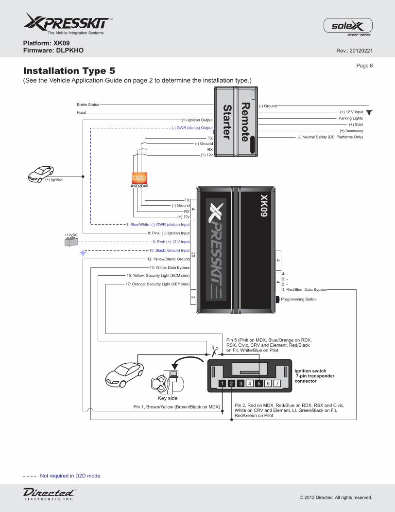
Installation Type 5(See the Vehicle Application Guide on page 2 to determine the installation type.)
Page 8
Not required in D2D mode.
4
42
4
Programming Button
XK
09
9: Red: (+) 12 V Input
8: Pink: (+) Ignition Input
10: Black: Ground Input
15: Yellow: Security Light (ECM side)
14: White: Data Bypass
12: Yellow/Black: Ground
17: Orange: Security Light (KEY side)
1: Blue/White: (-) GWR (status) Input
20
1: Red/Blue: Data Bypass
2: -
3: -
4: -
Rem
ote
Sta
rter
(-) Neutral Safety (DEI Platforms Only)
(+) Accessory
(+) Start
Parking Lights
(+) 12 V Input
(-) Ground
Hood
Brake Status
(+) Ignition Output
(+) Ignition
(-) GWR (status) Output
+12VDC
(+) 12v
RX
(-) Ground
TX
(+) 12v
RX
(-) Ground
TX
XKD2D65
Ignition switch7-pin transponderconnector
Pin 5 (Pink on MDX, Blue/Orange on RDX,RSX, Civic, CRV and Element, Red/Blackon Fit, White/Blue on Pilot
Pin 1, Brown/Yellow (Brown/Black on MDX) Pin 2, Red on MDX, Red/Blue on RDX, RSX and Civic,White on CRV and Element, Lt. Green/Black on Fit,Red/Green on Pilot
1 435 72 5 6
Key side
Rev.: 20120221
Platform: XK09Firmware: DLPKHO
The Mobile Integration Systems
© 2012 Directed. All rights reserved.

Installation Type 6(See the Vehicle Application Guide on page 2 to determine the installation type.)
* The Tach wire is an optional connection requiredon some remote starters not supporting tach signal in D2D.
Not required in D2D mode.
** Connect the Rearm wire only if the vehicle is equipped withautomatic headlights.
4
42
4
Programming Button
XK
09
(+) Accessory
(-) Ground
(+) 12 V
(+) Ignition 1
(+) Ignition 2
1: Red/Blue: Data Bypass
2: Pink/White: (+) Brake Output
(+) Brake Input
3: -
4: -
4: Blue/Red: (-) Push-to-Start Output
3: -
2: Green: (-) Door & Trunk Sense Output
1: Violet/White: (AC) Tach Output*
Rem
ote
Sta
rter
9: Red: (+) 12 V Input
10: Black: Ground Input
14: White: Data Bypass
19: Tan: CAN Low
20: Tan/Black: CAN High
12: Yellow/Black: Ground
13: Violet/Brown: (-) Hood Output
6: Red/White: (-) Trunk Input
5: Blue: (-) Unlock Input
3: Light Green: (-) Lock Input
1: Blue/White: (-) GWR (status) Input
20
(-) Door & Trunk Sense Input
(AC) Tach Input*
Brake Output: Required forrun safe feature.
Connection to ground
(-) GWR (status) Output
(-) Lock Output
(-) Unlock Output
(-) Trunk Output
(-) Hood Input
(-) Neutral Safety (DEI Platforms Only)
17
23
71
6
Power Control Unit(Keyless Access)
, Light Blue(left side of steering column)
Connector F
Pin 7, Light Blue
Pin 16, Pink
Pin 17, Blue
35
34
25
12
34
56
89
10
11
12
13
14
15
18
19
20
21
22
23
24
26
27
28
29
30
31
32
33
36
17
16
7
23
11
Power ControlUnit, +12VConnector A, White
B
Driver Under Dash Fuse/Relay Box
(bottom of fuse box)Connector D, Light Green
Pin 5Light Green
(+) Starter Wire
Blue
Red
Orange
(+) Ignition 1
(+) Ignition 2
(+) Accessory
Power Control UnitConnector B, White
A
1
2
3
4
1
3
4
2 3 41
8
7
139 10 11
6
12
5
Keyless Access Control Unit(Keyless Access)
, Gray(left side of steering column)
Connector E
21
27
4
21
27
21
19
18
17
20
22
23
24
25
26
28
29
30
31
32
12
35
67
89
10
11
12
13
14
15
16
Pin 21, Light Green
Page 9
Combination Light SwitchConnector C, Black(at steering column)
Pin 11, Gray(-) Parking Lights
(+) Start
Rearm (Autolight Off)**
(-) Parking Lights
+12VDC
Warning�
�
No takeover feature is available.The engine will stop if a door isopened.To remote start the engine, alldoors must be closed.
(+) 12v
RX
(-) Ground
TX
(+) 12v
RX
(-) Ground
TX
XKD2D65
Rev.: 20120221
Platform: XK09Firmware: DLPKHO
The Mobile Integration Systems
© 2012 Directed. All rights reserved.

D
Under left-side of dash
Fu
se
/Re
lay
Bo
x
A
B
Key
less
Access
Unit
PowerControl
Unit
F
E
Bypass Data LineLight Green
Key slotwire
StarterLight Green
Acura TLDriver Dash Fuse Box
13-pin Light GreenConnector
Acura TLKeyless Access Control Unit
32-pin Gray Connector
Keyless Switch CAN LowBlue wire
CAN HighPink wire
Acura TL (Smart Key)Power Control Unit36-pin Light Blue
Connector
SS2
Locating Components in the Acura TL (Type 6)Page 10
Rev.: 20120221
Platform: XK09Firmware: DLPKHO
The Mobile Integration Systems
© 2012 Directed. All rights reserved.

(-) Hood Input
3: Red: (+) Ignition 2
4: Blue: (+) Ignition 1
Installation Type 7(See the Vehicle Application Guide on page 2 to determine the installation type.)
4
42
4
Programming Button
XK
09
(+) 12 V
(-) Ground
(+) Accessory
(+) Ignition 2
(+) Ignition 1
1: Red/Blue: Data Bypass
2: Pink/White: (+) Brake Output
(+) Brake Input
3: -
4: -
4: Blue/Red: (-) Push-to-Start Output
3: -
2: Green: (-) Door & Trunk Sense Output
1: Violet/White: (AC) Tach Output*
Rem
ote
Sta
rter
9: Red: (+) 12 V Input
10: Black: Ground Input
14: White: Data Bypass
19: Tan: CAN Low
20: Tan/Black: CAN High
12: Yellow/Black: Ground
13: Violet/Brown: (-) Hood Output
6: Red/White: (-) Trunk Input
5: Blue: (-) Unlock Input
3: Light Green: (-) Lock Input
1: Blue/White: (-) GWR (status) Input
20
(-) Door & Trunk Sense Input
(AC) Tach Input*
Brake Output: Required forrun safe feature.
(-) GWR (status) Output
(-) Lock Output
(-) Unlock Output
(-) Trunk Output
(+) Start(-) Neutral Safety (DEI Platforms Only)
17
23
71
6
Power Control Unit(Keyless Access)
, Light Blue(left side of steering column)
Connector F
Pin 7, Purple
Pin 10, Light Green
Pin 16, Pink
Pin 17, Blue
35
34
25
12
34
56
89
10
11
12
13
14
15
18
19
20
21
22
23
24
26
27
28
29
30
31
32
33
36
17
16
7
23
11
Power ControlUnit, +12V
Connector A, White
B
1: Orange: (+) Accessory
Power Control UnitConnector B, White
A
1
2
3
4
1
3
4
Page 11
Pin 10Light Green
Combination Light SwitchConnector C, Black(at steering column)
Pin 11, White(-) Parking Lights
Rearm (Autolight Off)**
(-) Parking Lights
Warning�
�
No takeover feature is available.The engine will stop if a door isopened.To remote start the engine, alldoors must be closed.
+12VDC
* The Tach wire is an optional connection requiredon some remote starters not supporting tach signal in D2D.
Not required in D2D mode.
** Connect the Rearm wire only if the vehicle is equipped withautomatic headlights.
Passenger Kick C206, WhiteConnector D
27
14
13
12
11
10
98
76
54
3
26
25
24
23
22
21
20
19
18
17
16
15
28
21
Connection to ground
(+) 12v
RX
(-) Ground
TX
(+) 12v
RX
(-) Ground
TX
XKD2D65
Rev.: 20120221
Platform: XK09Firmware: DLPKHO
The Mobile Integration Systems
© 2012 Directed. All rights reserved.

Acura ZDXCombinationLight Switch
�
�
Combination Light Switch:
Power Control Unit:At steering column.
Underneath the left side of the steering column.� Fuse Box:
Passenger kick panel.
Locating Components in the Acura ZDX (Type 7)Page 12
Power ControlUnit
Fuse BoxCombinationLight Switch
A
B D
F
C
Rev.: 20120221
Platform: XK09Firmware: DLPKHO
The Mobile Integration Systems
© 2012 Directed. All rights reserved.

(-) Hood Input
Installation Type 8(See the Vehicle Application Guide on page 2 to determine the installation type.)
Page 13
** Connect the Rearm wire only if the vehicle is equipped with automatic headlights.*** Only supported if the vehicle has the function on the remote starter. It is also important to note that this function will not work when the engine is running.
* The Tach wire is an optional connection required on some remote starters not supporting tach signal in D2D.
Not required in D2D mode.
4
42
4
Programming Button
XK
09
9: Red: (+) 12 V Input
10: Black: Ground Input
14: White: Data Bypass
12: Yellow/Black: Ground
20: Tan/Black: CAN High
19: Tan: CAN Low
6: Red/White: (-) Trunk/Hatch Input***
5: Blue: (-) Unlock Input
3: Light Green: (-) Lock Input
4: White/Violet: Aux 1 Passenger Slide Door Input***
2: Violet/Black: (-) Aux 2 Driver Sliding Door Input***
1: Blue/White: (-) GWR (status) Input20
Pin 2, Purple
Pin 1, Brown
(-) Neutral Safety (DEI Platforms Only)
(+) Accessory
(+) Ignition
(+) Start
(+) 12 V Input
1: Red/Blue: Data Bypass
2: -
3: -
4: -
3: Gray: (-) Handbrake Sense Output
4: -
2: Green: (-) Door & Trunk Sense Output
1: Violet/White: (AC) Tach Output*
Rem
ote
Sta
rter
(-) Handbrake Status Input
(-) Door & Trunk Sense Input
(AC) Tach Input*
(-) Ground
13: Violet/Brown: (-) Hood Output
(-) GWR (status) Output
(-) Lock Output
(-) Aux 1 Passenger Slide Door Output***
(-) Aux 2 Driver Sliding Door Output***
(-) Unlock Output
(-) Trunk/Hatch Output***
Rearm (Autolight Off)**
(-) Parking Lights(-) Parking Lights (at Light Switch)
+12VDC
CAN LowPin 5, Dark Blue
CAN HighPin 4, Pink
(+) 12v
RX
(-) Ground
TX
(+) 12v
RX
(-) Ground
TX
XKD2D65
Ignition switch7-pin transponderconnector
1 435 72 5 6
Rev.: 20120221
Platform: XK09Firmware: DLPKHO
The Mobile Integration Systems
© 2012 Directed. All rights reserved.
(-) Hood Input
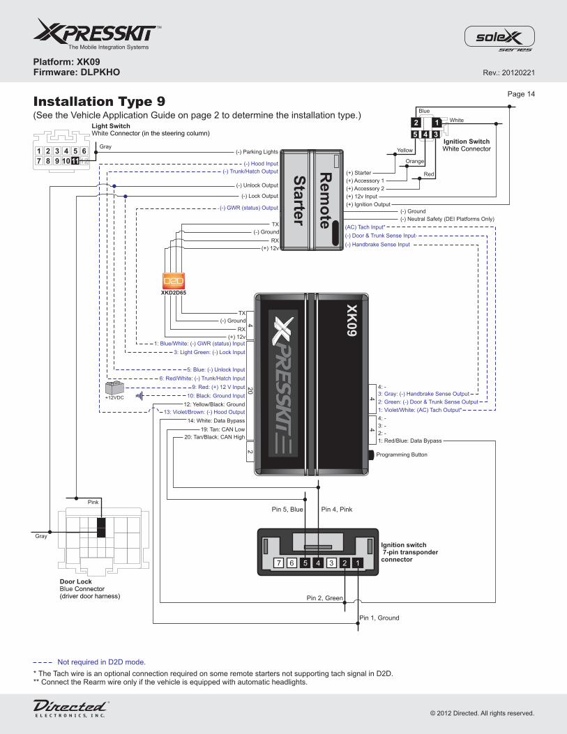
Installation Type 9(See the Vehicle Application Guide on page 2 to determine the installation type.)
Page 14
** Connect the Rearm wire only if the vehicle is equipped with automatic headlights.* The Tach wire is an optional connection required on some remote starters not supporting tach signal in D2D.
Not required in D2D mode.
4
42
4
Programming Button
XK
09
9: Red: (+) 12 V Input
10: Black: Ground Input
14: White: Data Bypass
12: Yellow/Black: Ground
20: Tan/Black: CAN High
19: Tan: CAN Low
6: Red/White: (-) Trunk/Hatch Input
5: Blue: (-) Unlock Input
3: Light Green: (-) Lock Input
1: Blue/White: (-) GWR (status) Input
20
Pin 4, PinkPin 5, Blue
Pin 2, Green
Pin 1, Ground
Ignition switch7-pin transponderconnector
7 4
(-) Neutral Safety (DEI Platforms Only)
1: Red/Blue: Data Bypass
2: -
3: -
4: -
3: Gray: (-) Handbrake Sense Output
4: -
2: Green: (-) Door & Trunk Sense Output
1: Violet/White: (AC) Tach Output*
Rem
ote
Sta
rter
(-) Handbrake Sense Input
(-) Door & Trunk Sense Input
(AC) Tach Input*
13: Violet/Brown: (-) Hood Output
(-) GWR (status) Output
(-) Lock Output
(-) Unlock Output
(-) Trunk/Hatch Output
+12VDC
12
6
10
4
9
3
8
2
7
1
11
5 (-) Parking Lights
Light SwitchWhite Connector (in the steering column)
Gray
(-) Ground
5 4 3
12
(+) Starter
(+) Accessory 2
(+) Accessory 1
(+) 12v Input
(+) Ignition Output
Blue
Yellow
Orange
Red
White
Ignition SwitchWhite Connector
Door LockBlue Connector(driver door harness)
Pink
Gray
16 3 2
(+) 12v
RX
(-) Ground
TX
(+) 12v
RX
(-) Ground
TX
XKD2D65
5
Rev.: 20120221
Platform: XK09Firmware: DLPKHO
The Mobile Integration Systems
© 2012 Directed. All rights reserved.
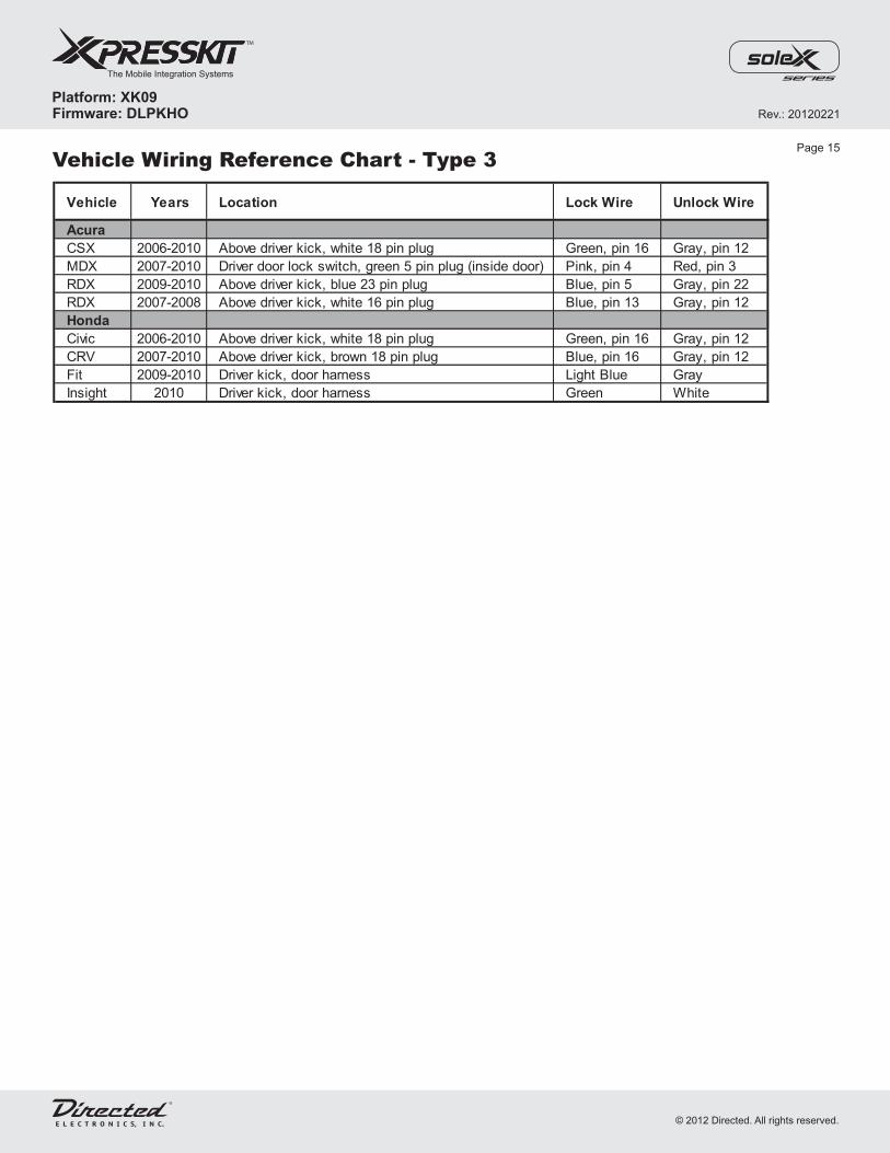
Vehicle Wiring Reference Chart - Type 3
Vehicle Years Location Lock Wire Unlock Wire
Acura
CSX 2006-2010 Above driver kick, white 18 pin plug Green, pin 16 Gray, pin 12
MDX 2007-2010 Driver door lock switch, green 5 pin plug (inside door) Pink, pin 4 Red, pin 3
RDX 2009-2010 Above driver kick, blue 23 pin plug Blue, pin 5 Gray, pin 22
RDX 2007-2008 Above driver kick, white 16 pin plug Blue, pin 13 Gray, pin 12
Honda
Civic 2006-2010 Above driver kick, white 18 pin plug Green, pin 16 Gray, pin 12
CRV 2007-2010 Above driver kick, brown 18 pin plug Blue, pin 16 Gray, pin 12
Fit 2009-2010 Driver kick, door harness Light Blue Gray
Insight 2010 Driver kick, door harness Green White
Page 15
Rev.: 20120221
Platform: XK09Firmware: DLPKHO
The Mobile Integration Systems
© 2012 Directed. All rights reserved.

Module Programming - Install Types 1, 2, 3, 4, 6, 7, 8 and 9Page 16
Refer to the LED Diagnostics section on page 18 for more information and for troubleshooting purposes.
2
3
Insert the key into the ignition barrel and turn it to ON
.Wait for the LED to turn OFF.
(for Smart Key vehicles,i press the Push-to-Start button twicewithout pressing on the brake pedal)nsert the OEM remote into the key port then
Turn the key back to the OFF position and remove it from the ignition barrel(for Smart Key vehicles, press the Push-to-Start button once). The moduleis now programmed and ready to use.
1The LED turns ON solid.
If connected in D2D:Connect the 4-pin D2D and the 20-pin harnesses.
If connected in W2W:Connect the 20-pin harness.
Caution! The 20-pin connector can be easily plugged in backwards.
4-pin
20-pin
&KEY
Key at ON or press PTS
START
OF
F
ON
KEY
Remove Key
START
OF
F
ON
On Solid
Off
Module Programming - Install Type 5
3
4 Turn the key back to the OFF position and remove it from the ignition barrel.The module is now programmed and ready to use.
Insert and turn the key to ON After flashing, the LED turns ONsolid for 3 seconds and then turns OFF.
.
KEY
Remove Key
ON
START
OF
F
1The LED turns ON solid.
If connected in D2D:Connect the 4-pin D2D and the 20-pin harnesses.
If connected in W2W:Connect the 20-pin harness.
Caution! The 20-pin connector can be easily plugged in backwards.
4-pin
20-pin
& &KEY
Key at ON
START
OF
F
ON
2 Press and release the programming button. The LED flashes rapidly.
Refer to the LED Diagnostics section on page 18 for more information and for troubleshooting purposes.
On Solid
On x 3 Secs Off
&Press & Release Flashes
Rev.: 20120221
Platform: XK09Firmware: DLPKHO
The Mobile Integration Systems
© 2012 Directed. All rights reserved.

Page 17
Resetting the Module
1
2
3
Disconnect the module from any power source.
Press and HOLD the Integrated Programming Button (IPB).While holding the button, connect the module to the power source.
Wait until the red LED flashes once and release the Integrated ProgrammingButton (IPB). &
Release
Disconnect from Power
&Press & Hold Connect to Power
Flashes x1
Rev.: 20120221
Platform: XK09Firmware: DLPKHO
The Mobile Integration Systems
© 2012 Directed. All rights reserved.
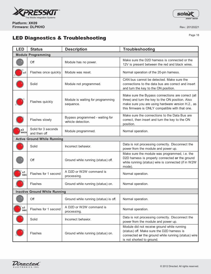
LED Status Description Troubleshooting
Module Programming
Off Module has no power.Make sure the D2D harness is connected or the
12V is present between the red and black wires.
Flashes once quickly Module was reset. Normal operation of the 20-pin harness.
Solid Module not programmed.
CAN bus cannot be detected. Make sure the
connections to the data bus are correct and insert
and turn the key to the ON position.
Flashes quicklyModule is waiting for programming
sequence.
Make sure the Bypass connections are correct (all
three) and turn the key to the ON position. Also
make sure you are using hardware version H.2., as
this firmware is ONLY compatible with that one.
Flashes slowlyBypass programmed - waiting for
vehicle detection.
Make sure the connections to the Data Bus are
correct, then insert and turn the key to the ON
position.
Solid for 3 seconds
and then offModule programmed. Normal operation.
Active Ground While Running
Solid Incorrect behavior.Data is not processing correctly. Disconnect the
power from the module and power up.
Off Ground while running (status) off.
Make sure the module was programmed, i.e. the
D2D harness is properly connected or the ground
while running (status) wire is connected (if in W2W
mode).
Flashes for 1 secondA D2D or W2W command is
processing.Normal operation.
Flashes Ground while running (status) on. Normal operation.
Inactive Ground While Running
Off Ground while running (status) is off. Normal operation.
Flashes for 1 secondA D2D or W2W command is
processing.Normal operation.
Solid Incorrect behavior.Data is not processing correctly. Disconnect the
power from the module and power up.
Flashes Ground while running (status) on.
Module did not receive ground while running
(status) off. Make sure the D2D harness is
connected or the ground while running (status) wire
is not shorted to ground.
LED Diagnostics & TroubleshootingPage 18
x1
x3secs
x1sec
x1sec
Rev.: 20120221
Platform: XK09Firmware: DLPKHO
The Mobile Integration Systems
© 2012 Directed. All rights reserved.
This Interface kit / Data Bus Interface part has been tested on the listed vehicles. Other vehicles will be added to the selectvehicle list upon completion of compatibility testing. Visit website for latest vehicle application guide. : Under nocircumstances shall the manufacturer or the distributors of the bypass kit / data bus interface part(s) be held liable for anyconsequential damages sustained in connection with the part(s) installation. The manufacturer and it’s distributors will not, norwill they authorize any representative or any other individual to assume obligation or liability in relation to the interface kit / databus interface part(s) other than its replacement.
DISCLAIMER
N.B.:Under no circumstances shall the manufacturer and distributors of thisproduct be liable for consequential damages sustained in connection with this product and neither assumes nor authorizesany representative or other person to assume for it any obligation or liability other than the replacement of this product only.
For a period of ONE YEAR from the date of purchase of a Directed Electronics remote start or security product, DirectedElectronics. (“DIRECTED”) promises to the original purchaser, to repair or replace with a comparable reconditioned piece, thesecurity or remote start accessory piece (hereinafter the “Part”), which proves to be defective in workmanship or material undernormal use, provided the following conditions are met: the Part was purchased from an authorized DIRECTED dealer; and thePart is returned to DIRECTED, postage prepaid, along with a clear, legible copy of the receipt or bill of sale bearing the followinginformation: consumer’s name, address, telephone number, the authorized licensed dealer’s name and complete product andPart description.
This warranty is nontransferable and is automatically void if the Part has been modified or used in a manner contrary to itsintended purpose or the Part has been damaged by accident, unreasonable use, neglect, improper service, installation orother causes not arising out of defect in materials or construction.
TO THE MAXIMUM EXTENT ALLOWED BY LAW, ALL WARRANTIES, INCLUDING BUT NOT LIMITED TO EXPRESSWARRANTY, IMPLIED WARRANTY, WARRANTY OF MERCHANTABILITY, FITNESS FOR PARTICULAR PURPOSE ANDWARRANTY OF NON INFRINGEMENT OF INTELLECTUAL PROPERTY, ARE EXPRESSLY EXCLUDED; AND DIRECTEDNEITHER ASSUMES NOR AUTHORIZES ANY PERSON OR ENTITY TO ASSUME FOR IT ANY DUTY, OBLIGATION ORLIABILITY IN CONNECTION WITH ITS PRODUCTS. DIRECTED HEREBY DISCLAIMS AND HAS ABSOLUTELY NOLIABILITY FOR ANY AND ALL ACTS OF THIRD PARTIES INCLUDING DEALERS OR INSTALLERS. IN THE EVENT OF ACLAIM OR A DISPUTE INVOLVING DIRECTED OR ITS SUBSIDIARY, THE PROPER VENUE SHALL BE SAN DIEGOCOUNTY IN THE STATE OF CALIFORNIA. CALIFORNIASTATE LAWSAND APPLICABLE FEDERAL LAWS SHALLAPPLYAND GOVERN THE DISPUTE. THE MAXIMUM RECOVERY UNDER ANY CLAIM AGAINST DIRECTED SHALL BESTRICTLY LIMITED TO THE AUTHORIZED DIRECTED DEALER’S PURCHASE PRICE OF THE PART. DIRECTED SHALLNOT BE RESPONSIBLE FOR ANY DAMAGES WHATSOEVER, INCLUDING BUT NOT LIMITED TO, ANYCONSEQUENTIAL DAMAGES, INCIDENTAL DAMAGES, DAMAGES FOR THE LOSS OF TIME, LOSS OF EARNINGS,COMMERCIAL LOSS, LOSS OF ECONOMIC OPPORTUNITY AND THE LIKE. NOTWITHSTANDING THE ABOVE, THEMANUFACTURER DOES OFFER A LIMITED WARRANTY TO REPLACE OR REPAIR AT DIRECTED’S OPTION THE PARTAS DESCRIBEDABOVE.
Some states do not allow limitations on how long an implied warranty will last or the exclusion or limitation of incidental orconsequential damages. This warranty gives you specific legal rights and you may also have other rights that vary fromState to State. DIRECTED does not and has not authorized any person or entity to create for it any other obligation,promise, duty or obligation in connection with this Part.920-0007 07-06
PROTECTED BY U.S. PATENTS:
CDN. PATENT:EUROPEAN PATENT: PAT. PENDING: MADE IN CANADA2,291,306;
5,719,551; 6,011,460 B1 *;6,243,004 B1; 6,249,216 B1; 6,275,147 B1; 6,297,731 B1; 6,346,876 B1; 6,392,534 B1; 6,529,124B2; 6,696,927 B2; 6,756,885 B1; 6,756,886 B2; 6,771,167 B1; 6,812,829 B1; 6,924,750 B1; 7,010,402 B1; 7,015,830 B1; 7,031,826 B1; 7 , 0 4 6 , 1 2 6 B 1 ;7,061,137 B1; 7,068,153 B1; 7,205,679 B1; 2,320,248; 2,414,991; 2,415,011; 2,415,023; 2,415,027; 2,415,038; 2,415,041; 2 , 4 2 0 , 9 4 7 ;2,426,670; 2,454,089 1,053,128
Limited One-Year Consumer WarrantyPage 19
Rev.: 20120221
Platform: XK09Firmware: DLPKHO
The Mobile Integration Systems
© 2012 Directed. All rights reserved.