Xilinx FPGA Configuration from Flash PROMs on the … · application files and the system...
20
XAPP978 (v1.2) November 5, 2010 www.xilinx.com 1 © Copyright 2007–2010 Xilinx, Inc. XILINX, the Xilinx logo, Virtex, Spartan, ISE, and other designated brands included herein are trademarks of Xilinx in the United States and other countries. All other trademarks are the property of their respective owners. Abstract This application note describes three FPGA configuration modes using Flash PROMs. These modes are BPI Up mode, BPI Down mode, and SPI mode. The step-by-step process to bootload a software application in flash in each of the configuration modes is detailed in this application note. The process includes creating the bootloader, programming the software application files and the system configuration into flash memory, and setting which configuration mode the FPGA will use when the board is powered on. The types of files used in the bootloading process are also described in this application note. A reference system is included with this application note that is targeted for the Spartan®-3E 1600E (SP3E1600E) development board. The reference system is configured for programming the Intel StrataFlash parallel NOR Flash PROM on the SP3E1600E board. Sample software applications are used with the reference system to illustrate the bootloading process described in this application note. Included Systems Included with this application note is one reference system built for the Spartan-3E 1600E development board. The reference system is available for download at: htt ps://secure.xilinx.com/webreg/clickthrough.do?cid=92902 Introduction Flash memory can be used for many purposes in which non-volatile storage is needed. A common use of non-volatile memory is the storage of software application code for bootloading. Bootloading allows a software application stored in flash memory to be executed when the board is powered on. This application note includes instructions for how to bootload a software application in BPI Up, BPI Down, and SPI configuration modes. The SP3E1600E development board features a 16 MB Intel StrataFlash parallel NOR Flash PROM and a 2 MB ST Microelectronics SPI serial Flash PROM. BPI Up and BPI Down modes configure the FPGA from an image stored in the StrataFlash PROM. SPI mode configures the FPGA from an image stored in the SPI Flash PROM. Hardware and Software Requirements The hardware and software requirements are: • SP3E1600E development board • USB download cable • RS232 serial cable and serial communications utility (e.g. HyperTerminal) • Xilinx Platform Studio (XPS) 9.1.01i • Xilinx ISE® Software 9.1.03i Application Note: Embedded Processing XAPP978 (v1.2) November 5, 2010 FPGA Configuration from Flash PROMs on the Spartan-3E 1600E Board Author: Casey Cain
Transcript of Xilinx FPGA Configuration from Flash PROMs on the … · application files and the system...

XAPP978 (v1.2) November 5, 2010 www.xilinx.com 1
© Copyright 2007–2010 Xilinx, Inc. XILINX, the Xilinx logo, Virtex, Spartan, ISE, and other designated brands included herein are trademarks of Xilinx in the United States and other countries. All other trademarks are the property of their respective owners.
Abstract This application note describes three FPGA configuration modes using Flash PROMs. These modes are BPI Up mode, BPI Down mode, and SPI mode. The step-by-step process to bootload a software application in flash in each of the configuration modes is detailed in this application note. The process includes creating the bootloader, programming the software application files and the system configuration into flash memory, and setting which configuration mode the FPGA will use when the board is powered on. The types of files used in the bootloading process are also described in this application note.
A reference system is included with this application note that is targeted for the Spartan®-3E 1600E (SP3E1600E) development board. The reference system is configured for programming the Intel StrataFlash parallel NOR Flash PROM on the SP3E1600E board. Sample software applications are used with the reference system to illustrate the bootloading process described in this application note.
Included Systems
Included with this application note is one reference system built for the Spartan-3E 1600E development board. The reference system is available for download at:
https://secure.xilinx.com/webreg/clickthrough.do?cid=92902
Introduction Flash memory can be used for many purposes in which non-volatile storage is needed. A common use of non-volatile memory is the storage of software application code for bootloading. Bootloading allows a software application stored in flash memory to be executed when the board is powered on. This application note includes instructions for how to bootload a software application in BPI Up, BPI Down, and SPI configuration modes. The SP3E1600E development board features a 16 MB Intel StrataFlash parallel NOR Flash PROM and a 2 MB ST Microelectronics SPI serial Flash PROM. BPI Up and BPI Down modes configure the FPGA from an image stored in the StrataFlash PROM. SPI mode configures the FPGA from an image stored in the SPI Flash PROM.
Hardware and Software Requirements
The hardware and software requirements are:
• SP3E1600E development board
• USB download cable
• RS232 serial cable and serial communications utility (e.g. HyperTerminal)
• Xilinx Platform Studio (XPS) 9.1.01i
• Xilinx ISE® Software 9.1.03i
Application Note: Embedded Processing
XAPP978 (v1.2) November 5, 2010
FPGA Configuration from Flash PROMson the Spartan-3E 1600E BoardAuthor: Casey Cain

Reference System Specifics
XAPP978 (v1.2) November 5, 2010 www.xilinx.com 2
Reference System Specifics
The reference system targets the SP3E1600E development board. The system uses the MicroBlaze™ processor with 8 KB for both the instruction cache and the data cache. The reference system includes the OPB UART Lite, OPB EMC, MCH OPB DDR, and OPB INTC IP cores. The OPB EMC is required in the reference system to interface to the StrataFlash memory for flash programming through the EDK tools. The reference system block diagram is shown in Figure 1 and the address map of the system is listed in Table 1.
Block Diagram
Address Map
Types of Flash Files
There are many types of files used to program flash memory. This section describes the flash files discussed in this application note, which are bootloader files, SREC files, and MCS files.
Bootloader Files
A hardware bitstream including the bootloader loaded into BRAM is stored in flash memory and used to configure the FPGA. When the processor comes out of reset, it starts executing the bootloader stored in BRAM. When the bootloader is run, it copies the software executable from a pre-determined location in the flash PROM to the DDR memory. The bootloader then changes addresses to the software application in DDR memory and executes the software application. The bootloader is designed to be small so that it fits in BRAM. The creation of a bootloader allows the software executable to be large since it can be stored in flash memory instead of BRAM.
X-Ref Target - Figure 1
Figure 1: Reference System Block Diagram
Table 1: Reference System Address Map
Instance Peripheral Base Address High Address
debug_module opb_mdm 0x41400000 0x4140FFFF
dlmb_cntlr lmb_bram_if_cntlr 0x00000000 0x00001FFF
ilmb_cntlr lmb_bram_if_cntlr 0x00000000 0x00001FFF
RS232_DTE opb_uartlite 0x40600000 0x4060FFFF
FLASH_16Mx8 opb_emc 0x21000000 0x21FFFFFF
DDR_SDRAM_32Mx16 mch_opb_ddr 0x22000000 0x23FFFFFF
opb_intc_0 opb_intc 0x41200000 0x4120FFFF
OPBUART Lite
MCH OPB DDR
MCH0
MCH1
OPB
DXCL IXCL
MicroBlazeProcessor
OPBINTC
OPBEMC
X978_01_121106

Configuration Options
XAPP978 (v1.2) November 5, 2010 www.xilinx.com 3
SREC Files
An S-record file consists of ASCII character strings, specially formatted for loading data into memory. For bootloading, software application executable ELF files are converted into SREC files to simplify the bootloader. This also allows the bootloader to be created with the EDK tools. Bootloading ELF files is not typically done because the complexity of the bootloader would be increased.
MCS Files
An MCS file contains ASCII strings that define the storage address and data for configuration. For bootloading, an MCS file is created from the hardware configuration bitstream with a small bootloader program loaded into BRAM.
Configuration Options
The SP3E1600E development board supports a variety of FPGA configuration options. This section explains the configuration options that are discussed in this application note.
BPI Up Mode
For this configuration mode, the on-board Intel StrataFlash parallel NOR Flash PROM is programmed, then the FPGA is configured from the image stored in the Flash PROM. The FPGA configuration image source is stored in the StrataFlash PROM starting at address 0x00000000 and incrementing through address space.
BPI Down Mode
For this configuration mode, the on-board Intel StrataFlash parallel NOR Flash PROM is programmed, then the FPGA is configured from the image stored in the Flash PROM. The FPGA configuration image source is stored in the StrataFlash PROM starting at address 0x00FFFFFF and decrementing through address space.
SPI Mode
For this configuration mode, the on-board ST Microelectronics SPI serial Flash PROM is programmed, then the FPGA is configured from the image stored in the SPI serial Flash PROM.
Erasing the PROMs
Before programming new files into the StrataFlash and SPI Flash memories, be sure to erase the flash memories completely. Anytime a file will need to be programmed at a location that already has data, that location will need to be erased first. Failure to erase the flash memory can cause the flash files to operate incorrectly.
The Xilinx PicoBlaze™ NOR Flash Programmer can be used to completely erase the StrataFlash memory and the PicoBlaze SPI Flash Programmer can be used to completely erase the SPI Flash memory. The files for the PicoBlaze Programmers can be found at the following website:
http://www.xilinx.com/products/boards/s3e1600e/reference_designs.htm
From that website, the PicoBlaze NOR Flash Programmer files and the PicoBlaze SPI Flash Programmer files can be found under the Spartan-3E MicroBlaze Development Kit Design Examples link. Refer to the PDF files for instruction on how to erase both flash memories.

Configuration Using BPI Up Mode
XAPP978 (v1.2) November 5, 2010 www.xilinx.com 4
Configuration Using BPI Up Mode
To showcase how to use the BPI Up configuration mode, the simple memory test application will be used as a sample software application to program the flash memory. A pre-built bitstream and memory test software application executable are included with the reference system in the ready_for_download directory. This section describes how to configure the FPGA using BPI Up mode.
Creating Bootloader and SREC Files
Bootloader files and SREC files can be generated in XPS. The bootloader files generated by XPS are designed to boot an image file in SREC format given the address in memory where the image will be stored. A generated SREC file for the memory test application is included in the ready_for_download/flash_files directory or a new file can be created with the reference system. This section describes how to create the bootloader files, create an SREC file, and store the SREC file in flash.
1. Open the reference system project in XPS.
2. Connect the USB programming cable, the serial cable, and the power supply to the SP3E1600E development board. Power on the board.
3. The target board must be configured with the project bitstream before XPS can program the SREC file into the flash memory. Select Device Configuration → Download Bitstream in XPS.
4. Compile the memory test software application by selecting Software → Build all User Applications in XPS.
5. In XPS, select Device Configuration → Program Flash Memory.
Configuration Using BPI Up Mode
XAPP978 (v1.2) November 5, 2010 www.xilinx.com 5
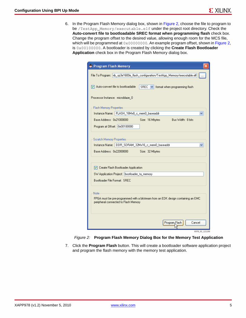
6. In the Program Flash Memory dialog box, shown in Figure 2, choose the file to program to be /TestApp_Memory/executable.elf under the project root directory. Check the Auto-convert file to bootloadable SREC format when programming flash check box. Change the program offset to the desired value, allowing enough room for the MCS file, which will be programmed at 0x00000000. An example program offset, shown in Figure 2, is 0x00100000. A bootloader is created by clicking the Create Flash Bootloader Application check box in the Program Flash Memory dialog box.
7. Click the Program Flash button. This will create a bootloader software application project and program the flash memory with the memory test application.
X-Ref Target - Figure 2
Figure 2: Program Flash Memory Dialog Box for the Memory Test Application
X978_02_121106
Configuration Using BPI Up Mode
XAPP978 (v1.2) November 5, 2010 www.xilinx.com 6
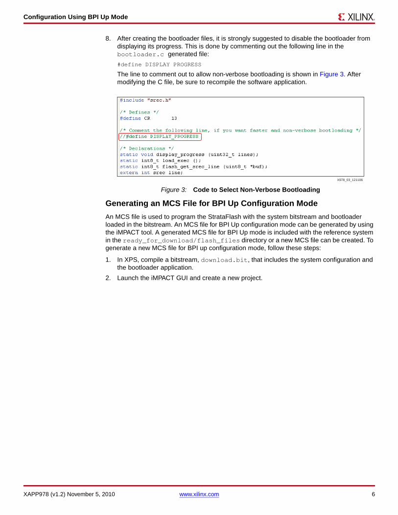
8. After creating the bootloader files, it is strongly suggested to disable the bootloader from displaying its progress. This is done by commenting out the following line in the bootloader.c generated file:
#define DISPLAY PROGRESS
The line to comment out to allow non-verbose bootloading is shown in Figure 3. After modifying the C file, be sure to recompile the software application.
Generating an MCS File for BPI Up Configuration Mode
An MCS file is used to program the StrataFlash with the system bitstream and bootloader loaded in the bitstream. An MCS file for BPI Up configuration mode can be generated by using the iMPACT tool. A generated MCS file for BPI Up mode is included with the reference system in the ready_for_download/flash_files directory or a new MCS file can be created. To generate a new MCS file for BPI up configuration mode, follow these steps:
1. In XPS, compile a bitstream, download.bit, that includes the system configuration and the bootloader application.
2. Launch the iMPACT GUI and create a new project.
X-Ref Target - Figure 3
Figure 3: Code to Select Non-Verbose Bootloading
X978_03_121106
Configuration Using BPI Up Mode
XAPP978 (v1.2) November 5, 2010 www.xilinx.com 7
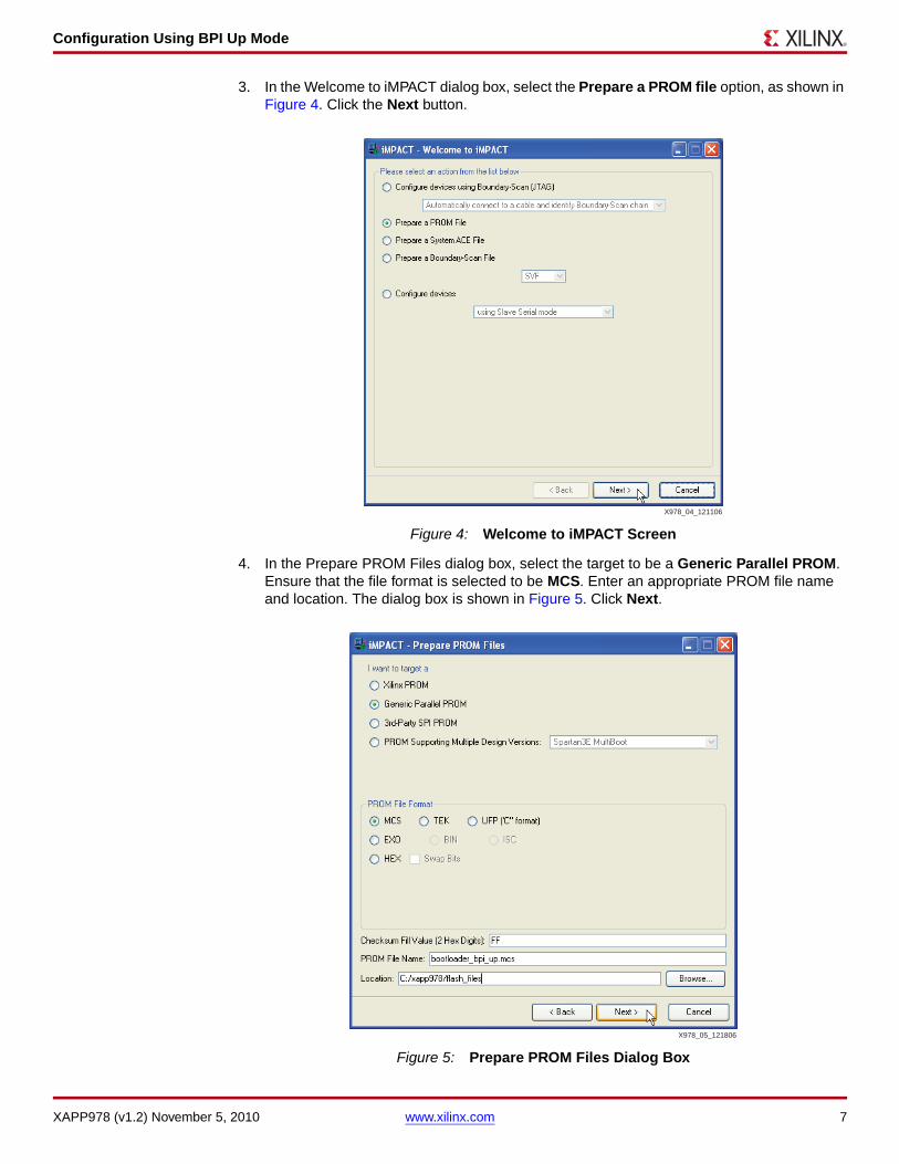
3. In the Welcome to iMPACT dialog box, select the Prepare a PROM file option, as shown in Figure 4. Click the Next button.
4. In the Prepare PROM Files dialog box, select the target to be a Generic Parallel PROM. Ensure that the file format is selected to be MCS. Enter an appropriate PROM file name and location. The dialog box is shown in Figure 5. Click Next.
X-Ref Target - Figure 4
Figure 4: Welcome to iMPACT Screen
X-Ref Target - Figure 5
Figure 5: Prepare PROM Files Dialog Box
X978_04_121106
X978_05_121806

Configuration Using BPI Up Mode
XAPP978 (v1.2) November 5, 2010 www.xilinx.com 8
5. In the Specify Parallel PROM Device dialog box, shown in Figure 6, select a parallel PROM density of 16M and click Add. Ensure the Number of Data Streams is set to 1, the Loading Direction is set to UP, and the Data Stream 0 Start Address is set to 0. Click Next.
6. In the File Generation Summary dialog box, click Finish.
7. The iMPACT screen will prompt for a device file to be added to Data Stream: 0. Select the download.bit file in the BPI reference system project. When asked to add another design file to Data Stream: 0, click No. Click OK.
8. Select Operations → Generate File... in iMPACT to generate the MCS file.
Loading an MCS File into StrataFlash
The Xilinx PicoBlaze NOR Flash Programmer is used to load an MCS file into the StrataFlash. To download the files for the PicoBlaze NOR Flash Programmer for the SP3E1600E board, refer to the following link:
http://www.xilinx.com/products/boards/s3e1600e/reference_designs.htm
From that website, click on the Spartan-3E MicroBlaze Development Kit Design Examples link to find the PicoBlaze StrataFlash Programmer files. The PicoBlaze StrataFlash Programmer PDF file documents the steps necessary to load an MCS file into the StrataFlash memory. After following those steps, the MCS file will be loaded into the StrataFlash memory and the reference system configuration is ready to be run in BPI Up mode.
X-Ref Target - Figure 6
Figure 6: Specify Parallel PROM Device Dialog Box
X978_06_121106
Configuration Using BPI Up Mode
XAPP978 (v1.2) November 5, 2010 www.xilinx.com 9
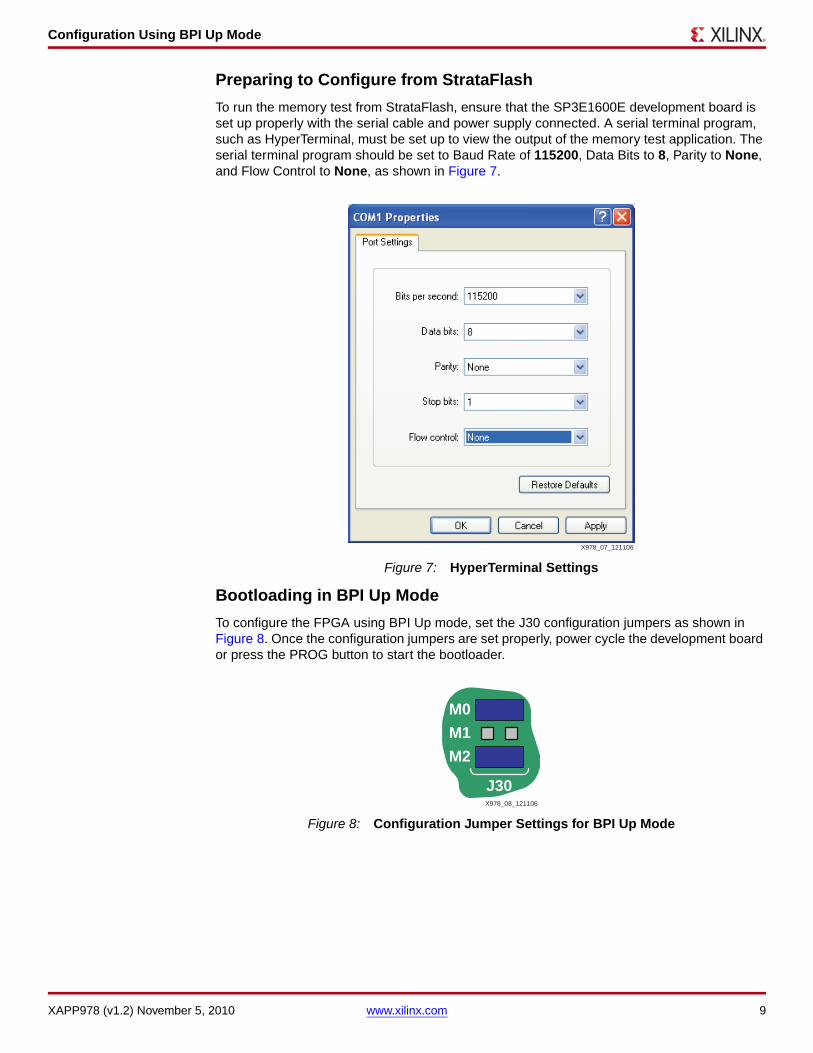
Preparing to Configure from StrataFlash
To run the memory test from StrataFlash, ensure that the SP3E1600E development board is set up properly with the serial cable and power supply connected. A serial terminal program, such as HyperTerminal, must be set up to view the output of the memory test application. The serial terminal program should be set to Baud Rate of 115200, Data Bits to 8, Parity to None, and Flow Control to None, as shown in Figure 7.
Bootloading in BPI Up Mode
To configure the FPGA using BPI Up mode, set the J30 configuration jumpers as shown in Figure 8. Once the configuration jumpers are set properly, power cycle the development board or press the PROG button to start the bootloader.
X-Ref Target - Figure 7
Figure 7: HyperTerminal Settings
X-Ref Target - Figure 8
Figure 8: Configuration Jumper Settings for BPI Up Mode
X978_07_121106
M0
M1
M2
J30X978_08_121106

Configuration Using BPI Down Mode
XAPP978 (v1.2) November 5, 2010 www.xilinx.com 10
The output after the bootloader runs reads as follows:
EDK Bootloader:
Executing program starting at address: 00000000
-- Entering main() --
Starting MemoryTest for DDR_SDRAM_32Mx16:
Running 32-bit test...PASSED!
Running 16-bit test...PASSED!
Running 8-bit test...PASSED!
-- Exiting main() --
Configuration Using BPI Down Mode
To showcase how to use the BPI Down configuration mode, the simple peripheral test application will be used as a sample software application to program the flash memory. A pre-built bitstream and peripheral test software application executable are included with the reference system in the ready_for_download directory. This section describes how to configure the FPGA using BPI Down mode.
Creating Bootloader and SREC Files
Bootloader files and SREC files can be generated in XPS. The bootloader files generated by XPS are designed to boot an image file in SREC format given the address in memory where the image will be stored. A generated SREC file for the peripheral test application is included in the ready_for_download/flash_files directory or a new file can be created with the reference system. This section describes how to create the bootloader files, create an SREC file, and store the SREC file in flash.
1. Open the reference system project in XPS.
2. Connect the USB programming cable, the serial cable, and the power supply to the SP3E1600E development board. Power on the board.
3. The target board must be configured with the project bitstream before XPS can program the SREC file into the flash memory. Select Device Configuration → Download Bitstream in XPS.
4. Compile the peripheral test software application by selecting Software → Build all User Applications in XPS.
5. In XPS, select Device Configuration → Program Flash Memory.

Configuration Using BPI Down Mode
XAPP978 (v1.2) November 5, 2010 www.xilinx.com 11
6. In the Program Flash Memory dialog box, shown in Figure 9, choose the file to program to be /TestApp_Peripheral/executable.elf under the project root directory. Check the Auto-convert file to bootloadable SREC format when programming flash check box. Change the program offset to the desired value, allowing enough room for the MCS file, which will be programmed down from 0x00FFFFFF. An example program offset, shown in Figure 9, is 0x00E00000. A bootloader is created by clicking the Create Flash Bootloader Application check box in the Program Flash Memory dialog box.
7. Click the Program Flash button. This will create a bootloader software application project and program the flash memory with the peripheral test application.
X-Ref Target - Figure 9
Figure 9: Program Flash Memory Dialog Box for the Peripheral Test Application
X978_09_121106
Configuration Using BPI Down Mode
XAPP978 (v1.2) November 5, 2010 www.xilinx.com 12
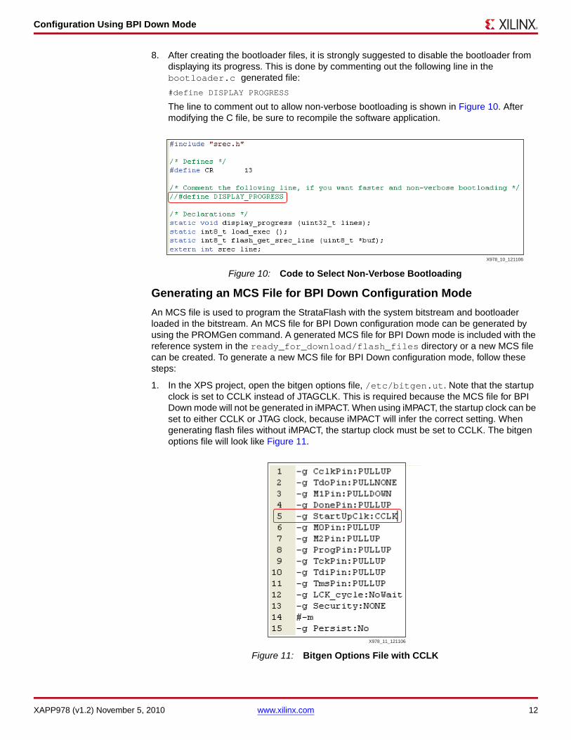
8. After creating the bootloader files, it is strongly suggested to disable the bootloader from displaying its progress. This is done by commenting out the following line in the bootloader.c generated file:
#define DISPLAY PROGRESS
The line to comment out to allow non-verbose bootloading is shown in Figure 10. After modifying the C file, be sure to recompile the software application.
Generating an MCS File for BPI Down Configuration Mode
An MCS file is used to program the StrataFlash with the system bitstream and bootloader loaded in the bitstream. An MCS file for BPI Down configuration mode can be generated by using the PROMGen command. A generated MCS file for BPI Down mode is included with the reference system in the ready_for_download/flash_files directory or a new MCS file can be created. To generate a new MCS file for BPI Down configuration mode, follow these steps:
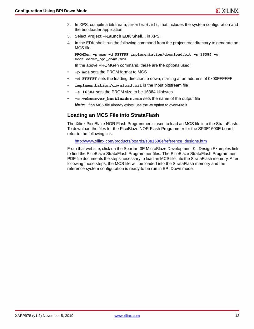
1. In the XPS project, open the bitgen options file, /etc/bitgen.ut. Note that the startup clock is set to CCLK instead of JTAGCLK. This is required because the MCS file for BPI Down mode will not be generated in iMPACT. When using iMPACT, the startup clock can be set to either CCLK or JTAG clock, because iMPACT will infer the correct setting. When generating flash files without iMPACT, the startup clock must be set to CCLK. The bitgen options file will look like Figure 11.
X-Ref Target - Figure 10
Figure 10: Code to Select Non-Verbose Bootloading
X-Ref Target - Figure 11
Figure 11: Bitgen Options File with CCLK
X978_10_121106
X978_11_121106
Configuration Using BPI Down Mode
XAPP978 (v1.2) November 5, 2010 www.xilinx.com 13
2. In XPS, compile a bitstream, download.bit, that includes the system configuration and the bootloader application.
3. Select Project → Launch EDK Shell... in XPS.
4. In the EDK shell, run the following command from the project root directory to generate an MCS file:
PROMGen -p mcs -d FFFFFF implementation/download.bit -s 16384 -o bootloader_bpi_down.mcs
In the above PROMGen command, these are the options used:
• -p mcs sets the PROM format to MCS
• -d FFFFFF sets the loading direction to down, starting at an address of 0x00FFFFFF
• implementation/download.bit is the input bitstream file
• -s 16384 sets the PROM size to be 16384 kilobytes
• -o webserver_bootloader.mcs sets the name of the output file
Note: If an MCS file already exists, use the -w option to overwrite it.
Loading an MCS File into StrataFlash
The Xilinx PicoBlaze NOR Flash Programmer is used to load an MCS file into the StrataFlash. To download the files for the PicoBlaze NOR Flash Programmer for the SP3E1600E board, refer to the following link:
http://www.xilinx.com/products/boards/s3e1600e/reference_designs.htm
From that website, click on the Spartan-3E MicroBlaze Development Kit Design Examples link to find the PicoBlaze StrataFlash Programmer files. The PicoBlaze StrataFlash Programmer PDF file documents the steps necessary to load an MCS file into the StrataFlash memory. After following those steps, the MCS file will be loaded into the StrataFlash memory and the reference system configuration is ready to be run in BPI Down mode.

Configuration Using BPI Down Mode
XAPP978 (v1.2) November 5, 2010 www.xilinx.com 14
Preparing to Configure from StrataFlash
To run the peripheral test from StrataFlash, ensure that the SP3E1600E development board is set up properly with the serial cable and power supply connected. A serial terminal program, such as HyperTerminal must be set up to view the output of the peripheral test application. The serial terminal program should be set to Baud Rate of 115200, Data Bits to 8, Parity to None, and Flow Control to None, as shown in Figure 12.
Bootloading in BPI Down Mode
To configure the FPGA using BPI Down mode, set the J30 configuration jumpers as shown in Figure 13. Once the configuration jumpers are set properly, power cycle the development board or press the PROG button to start the bootloader.
X-Ref Target - Figure 12
Figure 12: HyperTerminal Settings
X-Ref Target - Figure 13
Figure 13: Configuration Jumper Settings for BPI Down Mode
X978_07_121106
M0M1M2
J30X978_13_121106

Configuration Using SPI Mode
XAPP978 (v1.2) November 5, 2010 www.xilinx.com 15
The output after the bootloader runs reads as follows:
EDK Bootloader:
Executing program starting at address: 00000000
-- Entering main() --
Runnning IntcSelfTestExample() for opb_intc_0...
IntcSelfTestExample PASSED
Intc Interrupt Setup PASSED
Running UartLiteSelfTestExample() for debug_module...
UartLiteSelfTestExample PASSED
-- Exiting main() --
Configuration Using SPI Mode
To showcase how to use the SPI configuration mode, the simple memory test application loaded in StrataFlash will be used as a sample software application that the bootloader in SPI Flash memory will execute. A pre-built bitstream and memory test software application executable are included with the reference system in the ready_for_download directory. This section describes how to configure the FPGA using SPI mode and bootloading an executable file stored in the StrataFlash.
Creating Bootloader and SREC Files
The same bootloader and SREC files that were used for BPI Up configuration mode can be used for this example, which will load the configuration bitstream and bootloader into SPI flash, but the user application SREC file will remain in StrataFlash. To generate the bootloader and SREC files and load the SREC file into StrataFlash memory, refer to the section, Creating Bootloader and SREC Files, page 4.
Generating an MCS File for SPI Configuration Mode
An MCS file is used to program the SPI serial Flash with the system bitstream and bootloader loaded in the bitstream. An MCS file for SPI configuration mode can be generated by using the iMPACT tool. A generated MCS file for SPI mode is included with the reference system in the ready_for_download/flash_files directory or a new MCS file can be created. To generate a new MCS file for SPI configuration mode, follow these steps:
1. In XPS, compile a bitstream, download.bit, that includes the system configuration and the bootloader application.
2. Launch the iMPACT GUI and create a new project.
Configuration Using SPI Mode
XAPP978 (v1.2) November 5, 2010 www.xilinx.com 16
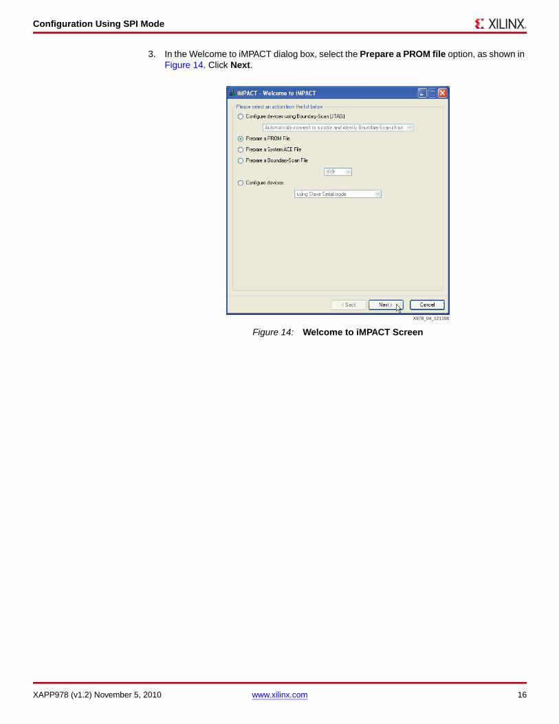
3. In the Welcome to iMPACT dialog box, select the Prepare a PROM file option, as shown in Figure 14. Click Next.
X-Ref Target - Figure 14
Figure 14: Welcome to iMPACT Screen
X978_04_121106
Configuration Using SPI Mode
XAPP978 (v1.2) November 5, 2010 www.xilinx.com 17
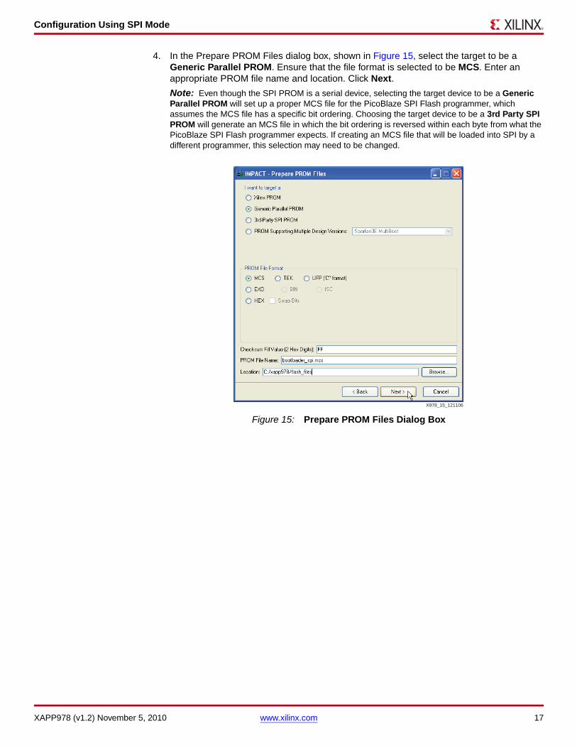
4. In the Prepare PROM Files dialog box, shown in Figure 15, select the target to be a Generic Parallel PROM. Ensure that the file format is selected to be MCS. Enter an appropriate PROM file name and location. Click Next.
Note: Even though the SPI PROM is a serial device, selecting the target device to be a Generic Parallel PROM will set up a proper MCS file for the PicoBlaze SPI Flash programmer, which assumes the MCS file has a specific bit ordering. Choosing the target device to be a 3rd Party SPI PROM will generate an MCS file in which the bit ordering is reversed within each byte from what the PicoBlaze SPI Flash programmer expects. If creating an MCS file that will be loaded into SPI by a different programmer, this selection may need to be changed.
X-Ref Target - Figure 15
Figure 15: Prepare PROM Files Dialog Box
X978_15_121106
Configuration Using SPI Mode
XAPP978 (v1.2) November 5, 2010 www.xilinx.com 18
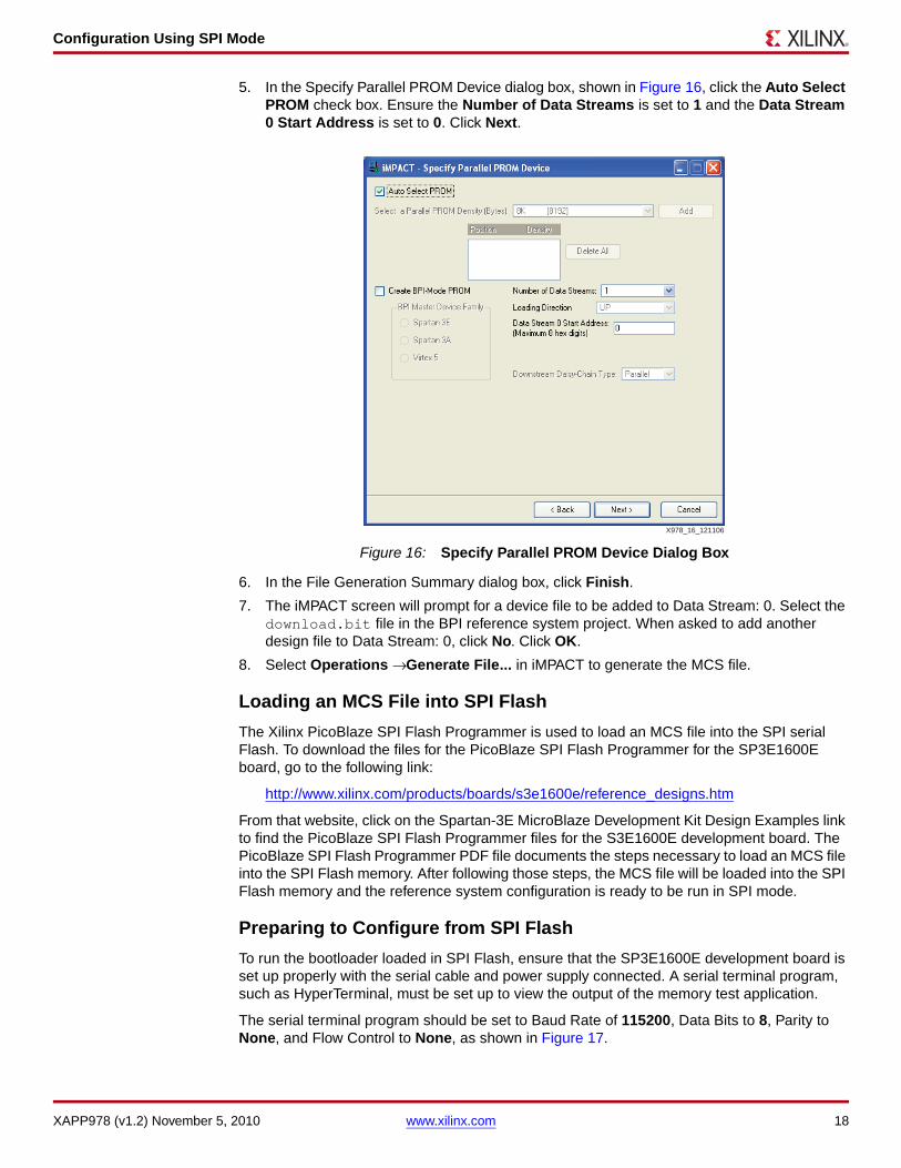
5. In the Specify Parallel PROM Device dialog box, shown in Figure 16, click the Auto Select PROM check box. Ensure the Number of Data Streams is set to 1 and the Data Stream 0 Start Address is set to 0. Click Next.
6. In the File Generation Summary dialog box, click Finish.
7. The iMPACT screen will prompt for a device file to be added to Data Stream: 0. Select the download.bit file in the BPI reference system project. When asked to add another design file to Data Stream: 0, click No. Click OK.
8. Select Operations → Generate File... in iMPACT to generate the MCS file.
Loading an MCS File into SPI Flash
The Xilinx PicoBlaze SPI Flash Programmer is used to load an MCS file into the SPI serial Flash. To download the files for the PicoBlaze SPI Flash Programmer for the SP3E1600E board, go to the following link:
http://www.xilinx.com/products/boards/s3e1600e/reference_designs.htm
From that website, click on the Spartan-3E MicroBlaze Development Kit Design Examples link to find the PicoBlaze SPI Flash Programmer files for the S3E1600E development board. The PicoBlaze SPI Flash Programmer PDF file documents the steps necessary to load an MCS file into the SPI Flash memory. After following those steps, the MCS file will be loaded into the SPI Flash memory and the reference system configuration is ready to be run in SPI mode.
Preparing to Configure from SPI Flash
To run the bootloader loaded in SPI Flash, ensure that the SP3E1600E development board is set up properly with the serial cable and power supply connected. A serial terminal program, such as HyperTerminal, must be set up to view the output of the memory test application.
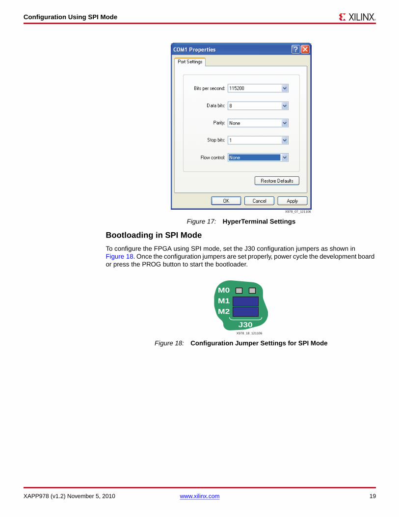
The serial terminal program should be set to Baud Rate of 115200, Data Bits to 8, Parity to None, and Flow Control to None, as shown in Figure 17.
X-Ref Target - Figure 16
Figure 16: Specify Parallel PROM Device Dialog Box
X978_16_121106
Configuration Using SPI Mode
XAPP978 (v1.2) November 5, 2010 www.xilinx.com 19
Bootloading in SPI Mode
To configure the FPGA using SPI mode, set the J30 configuration jumpers as shown in Figure 18. Once the configuration jumpers are set properly, power cycle the development board or press the PROG button to start the bootloader.
X-Ref Target - Figure 17
Figure 17: HyperTerminal Settings
X-Ref Target - Figure 18
Figure 18: Configuration Jumper Settings for SPI Mode
X978_07_121106
M0
M1
M2
J30X978_18_121106

Conclusion
XAPP978 (v1.2) November 5, 2010 www.xilinx.com 20
The output after the bootloader runs reads as follows:
EDK Bootloader:
Executing program starting at address: 00000000
-- Entering main() --
Starting MemoryTest for DDR_SDRAM_32Mx16:
Running 32-bit test...PASSED!
Running 16-bit test...PASSED!
Running 8-bit test...PASSED!
-- Exiting main() --
Conclusion This application note describes how to configure the FPGA in BPI Up mode, BPI Down mode, and SPI mode. The process to bootload from each of the configuration modes is given. The reference system, built for the SP3E1600E development board, is configured to be used in the bootloading process.
References 1. UG111, Embedded System Tools Reference Guide
2. UG257, MicroBlaze Development Kit Spartan-3E 1600E Edition User Guide
3. XAPP951, Configuring Xilinx FPGAs with SPI Serial Flash
4. Avnet Reference Design, Using Serial Flash on the Xilinx Spartan-3E Starter Board
Revision History
The following table shows the revision history for this document.
Notice of Disclaimer
Xilinx is disclosing this Application Note to you “AS-IS” with no warranty of any kind. This Application Noteis one possible implementation of this feature, application, or standard, and is subject to change withoutfurther notice from Xilinx. You are responsible for obtaining any rights you may require in connection withyour use or implementation of this Application Note. XILINX MAKES NO REPRESENTATIONS ORWARRANTIES, WHETHER EXPRESS OR IMPLIED, STATUTORY OR OTHERWISE, INCLUDING,WITHOUT LIMITATION, IMPLIED WARRANTIES OF MERCHANTABILITY, NONINFRINGEMENT, ORFITNESS FOR A PARTICULAR PURPOSE. IN NO EVENT WILL XILINX BE LIABLE FOR ANY LOSS OFDATA, LOST PROFITS, OR FOR ANY SPECIAL, INCIDENTAL, CONSEQUENTIAL, OR INDIRECTDAMAGES ARISING FROM YOUR USE OF THIS APPLICATION NOTE.
Date Version Revision
12/21/06 1.0 Initial Xilinx release.
6/4/07 1.1 Updated to EDK 9.1.01i
11/5/10 1.2 Updated links and references.