Xilink System Generator
23
For Academic Use Only Step by step tutorial on DSP using Xilinx System Generator (NOT HOMEWORK) DSP design using System Generator 1
Transcript of Xilink System Generator

For Academic Use Only
Step by step tutorial on DSP using Xilinx System Generator (NOT HOMEWORK)
DSP design using System Generator 1
DSP using Xilinx System Generator
Introduction
This Tutorial will introduce the design of DSP systems using Simulink, Matlab, and Xilinx System Generator tool. Xilinx offers a variety of high quality state of the art products for DSP design. We will work with field-programmable gate arrays (FPGAs). In order to do so, we need Simulink for development and verification of the design; and once we are happy with the results, System Generator will translate faithfully our design into FPGAs. SysGen will create the project files (HDL) that we can then synthesize, simulate, implement and download to the FPGA with Xilinx ISE Project Navegator.We will become familiar with the Xilinx tools using an example based approach. For this purpose, we will implement a digital filter using The Multiplier Accumulator (MAC) unit which is the basic element to implement a Digital filter on a FPGA.
Objectives
After completing this tutorial, you will be able to
Work with Xilinxs tools for DSP Understand the basics of DSP design using System Generator Generate HDL code for a desing through System Generator Import System Generator design to ISE Project Navegator. Generate a bit stream file to download to a FPGA using ISE
Design Description
Use System Generator under Simulink environment in Matlab to implement a FIR Digital Filter.
Type-I FIR Lowpass filter Filter of 6th order Use of multiple MACs to implement design.
DSP design using System Generator 2
Procedure
This tutorial will guide you through 6 steps: the first step will cover the basics of Simulink and System Generator and the remaining 5 will cover how to create your design using System Generator and implement it with Xilinx ISE Project Navegator. Step one is about Simulink, and step two goes over the Xilinx block set especially the Xilinx Gateways. In step 3, you will learn the different types of quantization and the effects of the sampling period. Sept 4 is about designing a Digital Filter using multiple MACs. In step 5, you will simulate the design while on step will teach you how to create VHDL code using System Generator.All steps are well documented and include figures for a better understanding. This are step-by-step explanations that can be skipped if you have some expertise using Simulink and System Generator.
Introduction to Simulink Step 1
Simulink is a software environment that runs under MATLAB. It provides a level of abstraction since it uses blocks to represent operations, so it is a block oriented design and the Xilinx block set is a library under Simulink. Create a blank worksheet, add the Sine Wave source element, add Scope sink element, and wire them up as shown in Figure 1
1. Open MATLAB command window by double-clicking the MATLAB icon on your desktop, or go to Start Menu → Programs → MATLAB7 → MATLAB7
Figure 1
DSP design using System Generator 3
2. Change the work directory to the folder C:\DSP\Tutorial by cd c:\DSP\Tutorial typing in the command window.
3. Launch Simulink: Type simulink at the MATLAB command prompt or click on the simulink button on the MATLAB tool bar to open the Simulink library browser.
Figure 2
4. Look at the blocks available in the Simulink Library Browser. The following elements, among others, should appear:
Simulink (sources and sinks) Signal Processing Blockset Xilinx Blockset Xilinx Reference Blockset
DSP design using System Generator 4

Figure 35. Right-click any block in the library browser, and choose Help from the
MATLAB menu.
DSP design using System Generator 5

Figure 4
Note: This provides details about the block. You can also use Help with the Xilinx blockset elements.
6. Create a “new model” blank sheet by clicking the Create a new model button of the Simulink Library Browser
Figure 5
7. In the library browser window, expand the Simulink Library, and click Sources
8. Add the Sine Wave source on the worksheet: Scroll through the library to find the Sine Wave, left click Sine Wave, and drag it onto the worksheet
9. Add the Scope sink element and write it to the Sine Wave source on the worksheet: From Simulink Simulink → Sinks , add the Scope block, and draw a wire from the Sine Wave to the Scope block
DSP design using System Generator 6

Figure 6
Note: To draw a wire, left-click source and drag mouse to destination
Assign a frequency of 2*pi*(1/150) to the Sine Wave element, show port data types, and change simulation parameter’s stop time to inf (infinity)
1. Double-click the Sine Wave block
The Block Parameters dialog box opens.
2. Change the frequency to 2*pi*(1/150) and click OK to close the dialog box
Figure 7
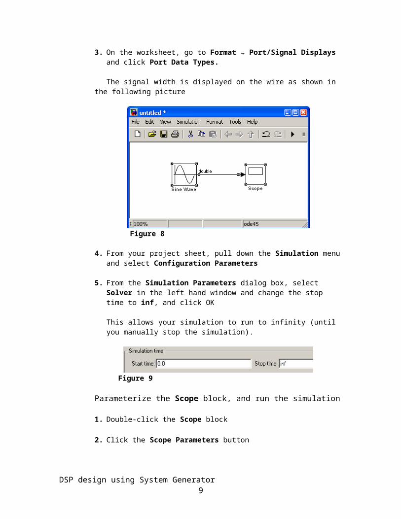
3. On the worksheet, go to Format → Port/Signal Displays and click Port Data Types.
The signal width is displayed on the wire as shown in the following picture
DSP design using System Generator 7

Figure 8
4. From your project sheet, pull down the Simulation menu and select Configuration Parameters
5. From the Simulation Parameters dialog box, select Solver in the left hand window and change the stop time to inf, and click OK
This allows your simulation to run to infinity (until you manually stop the simulation).
Figure 9
Parameterize the Scope block, and run the simulation
1. Double-click the Scope block
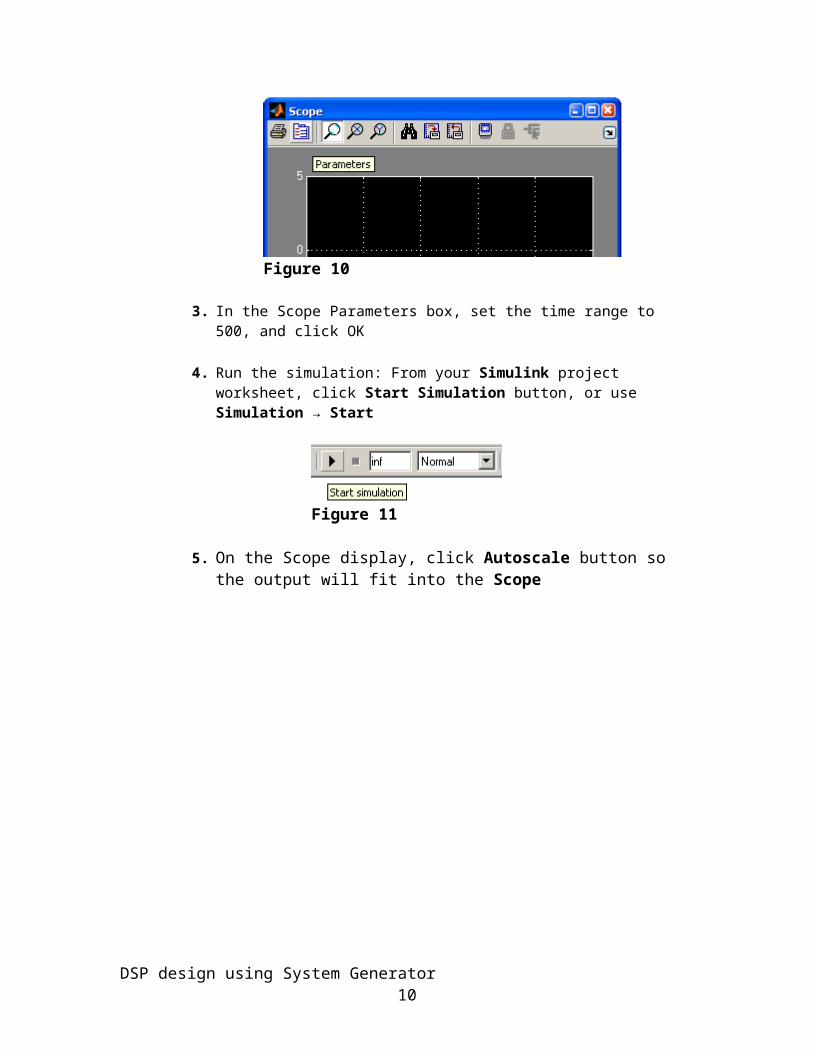
2. Click the Scope Parameters button
Figure 10
3. In the Scope Parameters box, set the time range to 500, and click OK
DSP design using System Generator 8
4. Run the simulation: From your Simulink project worksheet, click Start Simulation button, or use Simulation → Start
Figure 11
5. On the Scope display, click Autoscale button so the output will fit into the Scope
Figure 12
6. View the Scope output
A smooth sine wave should fit into your space window. This is what you would expect because you are running double-precision software simulation
The Xilinx Block Set, Gateways Step 2
Use the Xilinx Gateway In, Gateway Out, System Generator, and MUX blocks, as shown below, which provide interface to Xilinx Blocksets in Simulink.
DSP design using System Generator 9
1. Using Simulation → Configuration Parameters dialog box, set the stop time to 500, and click OK.
2. From the Xilinx Blockset (in the Simulink Library Browser), open Basic Elements and drag the Gateway In block onto the design sheet. Droop it on the connection between the Sine Wave and the output Scope. It will automatically insert itself.
Note: The Gateway In/Out blocks are required to convert double-precision floating point numbers used by Simulink in a simulation to bit fix point numbers used by Xilinx blocks. Thus, a conversion is required when communicating with Xilinx blocks and Simulink blocks.
3. Double-click Gateway In to open the Block Parameters
4. Set the Number of bits to 8 and Binary Point to 2
5. Similarly, drag a Gateway Out block onto the sheet, and drop it between the Gateway In block and the output Scope block
Figure 13
6. Add and connect a Simulink MUX between the Gateway Out and the Scope by using Simulink → Signal Routing
7. Add an additional net between the Sine Wave and the MUX
Note: This will make the scope display both the double-precision sine wave and the user-defined precision sine wave that has gone into and back out of the Xilinx gateways
DSP design using System Generator 10

8. Add a system generator token from the Xilinx Blockset → Basic Elements library to the design
9. To view the number of signals going into the MUX, select Wide nonscalar lines, Signal dimensions, and Port data types under the Format → Port/Signal Displays menu
Figure 14
10. Update the diagram: select Edit → Update Diagram
Figure 15
Note: Now look at your port types. Notice that the gateway in block has changed the signals from double-precision to fixed-point types. Fixed-point looks like Fix_8_2 in this case.
DSP design using System Generator 11

Analyze Precision, Quantization and Sample Rate Step 3
Run the simulation with default settings and understand and understand the output. Change the data type and simulate, and analyze the simulation output. Change the sampling period from one to five and see effect on the quantization.
Implement a Type-I FIR Filter Step 4
Implement a Type-I FIR Filter using Xilinx Blockset in Simulink. The desing characteristics are the following:
Separate multiplier and accumulator per filter coefficient Low Pass Filter of order 6 Coefficients generated using the FDA Xilinx Tool Sampling frequency of 1kHz
1. In the project sheet, select File → New → Model
A new Simulink project opens.
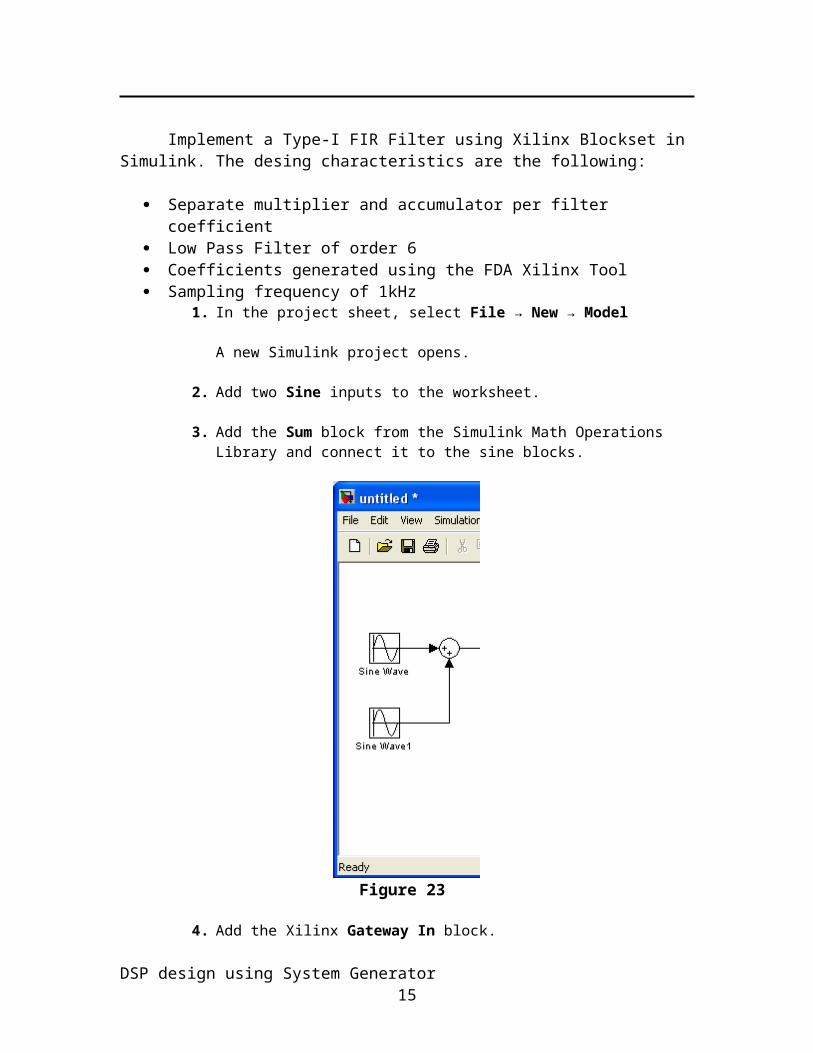
2. Add two Sine inputs to the worksheet.
3. Add the Sum block from the Simulink Math Operations Library and connect it to the sine blocks.
DSP design using System Generator 12

Figure 23
4. Add the Xilinx Gateway In block.
5. Add the Delay block from the Basic Elements library of the Xilinx Blockset.
6. Add the Xilinx Constant Block from the Basic Elements Xilinx Blockset.
7. Add the Xilinx Multiplier Block form the Index Xilinx Blockset.
DSP design using System Generator 13

Figure 24
8. Repeat step 5, 6, 7.
9. Add the Xilinx Adder/Substractor from the Index Xilinx Blockset.
Figure 25
DSP design using System Generator 14
10. Repeat steps 5, 6, 7, 8 until the design looks like figure
Figure 26
11. Add the Xilinx Gateway Out block
12. Add two Scope blocks and connect one to the sine inputs and the other to the output of the Gateway out and the output of the Sum block.
To increase the number of inputs to the scope, double-click on it, on the menu click on Parameters and change the number of axis.
Figure 27
13. Wire all the blocks and add the System Generator token from the Xilinx Basic Elements Library as well as the FDA Tool from the Xinlinx DSP Library.
DSP design using System Generator 15

The final diagram should look like figure 26
Simulate the Type-I FIR Filter Using Simulink Step 5
Configure the inputs and simulation parameters as specified below. Next, simulate the Filter in Simulink and verify the design functionality.
Two Sine inputs: low and high frequencies. 16 bit input: signed data (2’s complement) binary point 13, and sampling period
of 0.001 seconds. Multiplier Block latency of 1 and Full precision. Lowpass Type-I FIR filter of order 6. Simulation parameters: Stop time 0.5 seconds.
1. Set the frequencies of the sine inputs. One to 5Hz and the other to 300 Hz
2. Configure the inputs by double-clicking the Gateway In blocks to open their Parameters dialog box.
3. Set the Number of bits to 16 and the Binary Point to 14.
4. Set the Overflow to Saturate and Sample period to 0.001 seconds.
5. Design the six order low pass filter by double-clicking on the FDA Tool block
6. On Response Type choose Lowpass.
7. Set the Desing Method to FIR and from the bottom down menu select Least-squares.
8. Set the Filter Order to 6.
9. On Frequency Specifications select Normalized for the units and set the wpass to 0.1 and the wstop to 0.25.
DSP design using System Generator 16

Figure 28
10. Click on the Design Filter button.
11. Click on the File menu → Export and the Export window appears. Choose Export to Workspace and set the Variable Names to filter_coeff.
12. Click on Export botton.
13. On the Matlab workspace, double click the filter_coeff variable.
14. Click the View Menu → Numerical Array Format → long on Matlab.
15. Double click on the Xilinx Constant Block, set the Number of bits to 16, the Binary Point to 14 and Signed (2’s complement) type of data.
16. On the same block, edit the Constant value to the values of the filter_coeff variable accordingly to their position in the array.
Note: Do this for the seven coefficients. Do not change the order of the coefficients since each one of them is associated to a specific delay value and keep in mind that Matlab index start at 1 that corresponds to the first coefficient value which has no delay.
DSP design using System Generator 17

Figure 29
17. Double click on the System Generator block and se the Simulink System Period to 1/1000.
18. Save the design on your work directory as Lowpass.mdl and run the simulation by clicking on the Start Simulation button.
19. The graphs of the input and output should look like figure 30.
DSP design using System Generator 18

DSP design using System Generator 19

Figure 30
DSP design using System Generator 20