
Xgen Designers' Manual RevL 28 July 2011 - AC to DC Power ...€¦ · 50mm minimum clearance at...
19
page 1 gen Designers’ Manual This Xgen Designers’ Manual has been prepared by Excelsys experts to assist suitably qualified engineers and technicians in understanding the correct system design practices necessary to achieve maximum versatility and performance from any of the Xgen series family of products. 1 Overview of Xgen series 2 Part numbering system 3 Installation considerations 4 Xgen DOs and DON’Ts 5 Theory of operation 6 Xgen configuration 7 powerMod operation 8 powerMod signals 9 powerPac operation 10 powerPac (global) signals 11 powerPac options 12 Power ratings 13 Reliability 14 Safety 15 EMC 16 Connectors 17 Mechanical specifications Section 1 Overview of Xgen series The Xgen series allows users to instantly configure high efficiency, off-line power sup- plies. Although very small in size, (40.4mm high, 260mm long and either 89mm or 127mm wide) the Xgen series provides up to 1,200W of output power. The chassis has 4 or 6 slots and can provide up to 12 isolated outputs. A complete power supply is configured by selecting and inserting up to six same length slide-in output assemblies called powerMods incorporating high efficiency switching techniques and leading edge technologies from Excelsys and available in a wide array of output voltages and power levels. The net result is a power supply that offers the advantages of a custom supply, but is assembled from standard and modular building blocks continuing the Excelsys tradition of industry leading configurable power supplies. Manufactured in world class power supply facilities under Excelsys control, the Xgen series is completely user configurable. If output requirements change, i.e., more power or a different output voltage is needed, upgrading is easy: simply unlock a single screw and replace the slide-in powerMod assembly with the preferred alternative. Allowing additional flexibility, powerMods can be connected in parallel to increase output power, or in series for higher voltages (subject to staying within isolation ratings and giving due consideration to any SELV requirements. A user-friendly interface on connector J3 of each powerMod provides control and out- put sequencing capability, in addition to useful status indicators. Please consult our Excelsys applications team if you have other special requirements. The Xgen series power supplies combine feature-laden front-ends (powerPacs) with slide-in output converters (powerMods). The plug-together architecture facilitates ‘instant’ custom power solutions with industry leading 15W/in 3 power density and up to 90% conversion efficiency. Available in two package sizes, with a variety of application specific powerPacs, the Xgen series provides a standard off-the-shelf solution for spe- cific application requirements. The tables overleaf summarise various model families in the Xgen series together with a summary of the outline specifications for each model. www.excelsys.com Contents 18 Configuring Xgen
Transcript of Xgen Designers' Manual RevL 28 July 2011 - AC to DC Power ...€¦ · 50mm minimum clearance at...

page 1
genDesigners’ Manual
This Xgen Designers’ Manual has been prepared by Excelsys experts to assist
suitably qualified engineers and technicians in understanding the correct
system design practices necessary to achieve maximum versatility and
performance from any of the Xgen series family of products.
1 Overview of Xgen series
2 Part numbering system
3 Installation considerations
4 Xgen DOs and DON’Ts
5 Theory of operation
6 Xgen configuration
7 powerMod operation
8 powerMod signals
9 powerPac operation
10 powerPac (global) signals
11 powerPac options
12 Power ratings
13 Reliability
14 Safety
15 EMC
16 Connectors
17 Mechanical specifications
Section 1 Overview of Xgen series
The Xgen series allows users to instantly configure high efficiency, off-line power sup-
plies. Although very small in size, (40.4mm high, 260mm long and either 89mm or
127mm wide) the Xgen series provides up to 1,200W of output power. The chassis has
4 or 6 slots and can provide up to 12 isolated outputs.
A complete power supply is configured by selecting and inserting up to six same length
slide-in output assemblies called powerMods incorporating high efficiency switching
techniques and leading edge technologies from Excelsys and available in a wide array
of output voltages and power levels. The net result is a power supply that offers the
advantages of a custom supply, but is assembled from standard and modular building
blocks continuing the Excelsys tradition of industry leading configurable power supplies.
Manufactured in world class power supply facilities under Excelsys control, the Xgen
series is completely user configurable. If output requirements change, i.e., more power
or a different output voltage is needed, upgrading is easy: simply unlock a single screw
and replace the slide-in powerMod assembly with the preferred alternative. Allowing
additional flexibility, powerMods can be connected in parallel to increase output power,
or in series for higher voltages (subject to staying within isolation ratings and giving due
consideration to any SELV requirements.
A user-friendly interface on connector J3 of each powerMod provides control and out-
put sequencing capability, in addition to useful status indicators. Please consult our
Excelsys applications team if you have other special requirements.
The Xgen series power supplies combine feature-laden front-ends (powerPacs) with
slide-in output converters (powerMods). The plug-together architecture facilitates
‘instant’ custom power solutions with industry leading 15W/in3 power density and up to
90% conversion efficiency. Available in two package sizes, with a variety of application
specific powerPacs, the Xgen series provides a standard off-the-shelf solution for spe-
cific application requirements.
The tables overleaf summarise various model families in the Xgen series together with
a summary of the outline specifications for each model.
www.excelsys.com
Contents
18 Configuring Xgen
page 2
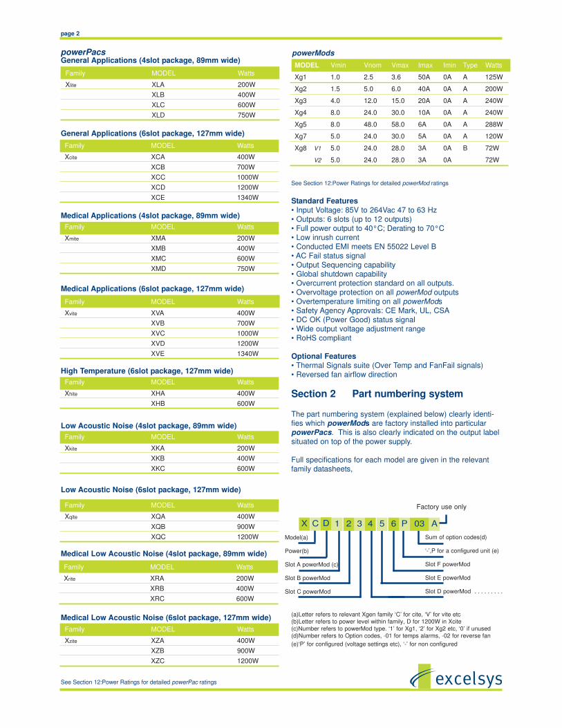
General Applications (4slot package, 89mm wide)
General Applications (6slot package, 127mm wide)
Medical Applications (4slot package, 89mm wide)
Medical Applications (6slot package, 127mm wide)
High Temperature (6slot package, 127mm wide)
Low Acoustic Noise (4slot package, 89mm wide)
Low Acoustic Noise (6slot package, 127mm wide)
Medical Low Acoustic Noise (4slot package, 89mm wide)
Medical Low Acoustic Noise (6slot package, 127mm wide)
See Section 12:Power Ratings for detailed powerPac ratings
See Section 12:Power Ratings for detailed powerMod ratings
Standard Features
• Input Voltage: 85V to 264Vac 47 to 63 Hz
• Outputs: 6 slots (up to 12 outputs)
• Full power output to 40°C; Derating to 70°C
• Low inrush current
• Conducted EMI meets EN 55022 Level B
• AC Fail status signal
• Output Sequencing capability
• Global shutdown capability
• Overcurrent protection standard on all outputs.
• Overvoltage protection on all powerMod outputs
• Overtemperature limiting on all powerMods
• Safety Agency Approvals: CE Mark, UL, CSA
• DC OK (Power Good) status signal
• Wide output voltage adjustment range
• RoHS compliant
Optional Features
• Thermal Signals suite (Over Temp and FanFail signals)
• Reversed fan airflow direction
Section 2 Part numbering system
The part numbering system (explained below) clearly identi-
fies which powerMods are factory installed into particular
powerPacs. This is also clearly indicated on the output label
situated on top of the power supply.
Full specifications for each model are given in the relevant
family datasheets,
(a)Letter refers to relevant Xgen family ‘C’ for cite, ‘V’ for vite etc
(b)Letter refers to power level within family, D for 1200W in Xcite
(c)Number refers to powerMod type. ‘1’ for Xg1, ‘2’ for Xg2 etc, ‘0’ if unused
(d)Number refers to Option codes, -01 for temps alarms, -02 for reverse fan
(e)‘P’ for configured (voltage settings etc), ‘-’ for non configured
powerModspowerPacs
Model(a)
Power(b)
Slot A powerMod (c)
Slot B powerMod
Slot C powerMod
Sum of option codes(d)
‘-’,P for a configured unit (e)
Slot F powerMod
Slot E powerMod
Slot D powerMod . . . . . . . . .
Factory use only
031 3 4 5 P A62
Family MODEL Watts
Xlite XLA 200W
XLB 400W
XLC 600W
XLD 750W
MODEL Vmin Vnom Vmax Imax Imin Type Watts
Xg1 1.0 2.5 3.6 50A 0A A 125W
Xg2 1.5 5.0 6.0 40A 0A A 200W
Xg3 4.0 12.0 15.0 20A 0A A 240W
Xg4 8.0 24.0 30.0 10A 0A A 240W
Xg5 8.0 48.0 58.0 6A 0A A 288W
Xg7 5.0 24.0 30.0 5A 0A A 120W
Xg8 V1 5.0 24.0 28.0 3A 0A B 72W
V2 5.0 24.0 28.0 3A 0A 72W
Family MODEL Watts
Xcite XCA 400W
XCB 700W
XCC 1000W
XCD 1200W
XCE 1340W
Family MODEL Watts
Xmite XMA 200W
XMB 400W
XMC 600W
XMD 750W
Family MODEL Watts
Xvite XVA 400W
XVB 700W
XVC 1000W
XVD 1200W
XVE 1340W
Family MODEL Watts
Xhite XHA 400W
XHB 600W
Family MODEL Watts
Xkite XKA 200W
XKB 400W
XKC 600W
Family MODEL Watts
Xqite XQA 400W
XQB 900W
XQC 1200W
Family MODEL Watts
Xrite XRA 200W
XRB 400W
XRC 600W
Family MODEL Watts
Xzite XZA 400W
XZB 900W
XZC 1200W
C DX

page 3
Section 3 Installation considerations
Xgen series models may be mounted on any of three sur-
faces using standard M4 screws. The chassis comes with four
mounting points on the base; maximum allowable torque is
2Nm. The maximum penetration depth is 6mm. Additionally,
the fleximountTM system on both side walls of the powerPac
chassis facilitates flexible mounting. See Section 17 for further
information.
When selecting a mounting location and orientation, the unit
should be positioned so air flow is not restricted. Maintain a
50mm minimum clearance at both ends of the Xgen power
supply and route all cables so airflow is not obstructed. The
standard unit draws air in on the input side and exhausts air
out the load side. If airflow ducting is used, avoid sharp turns
that could create back pressure. The fan moves 8.78 CFM of
air.
Avoid excessive bending of output power cables after they are
connected to the Xgen powerMods. For high-current outputs,
use cable-ties to support heavy cables and minimize mechan-
ical stress on output studs. Be careful not to short-out to
neighboring output studs. Xgen powerMods are supplied with
spring washers on all output screws. These (or equivalents)
should be used and thread locking compounds are not
required. The maximum torque recommended on output con-
nectors is 4Nm. Avoid applications in which the unit is
exposed to excessive shock or vibration levels that exceed
the specified levels. In such applications, a shock absorption
mounting design is required.
Section 4 Xgen DOs and DON’Ts
• Always fill all output slots of the Xgen. If a slot is not filled
with a powerMod, it should be filled with an Empty Slot Cover
(part numbers XB1,XB2 or XB3). Empty Slot covers are plas-
tic assemblies whose main function is to fill up an empty slot.
Excessive airflow escape from an empty slot may degrade
thermal performance, and result in overheating and damage
to the Xgen unit. Refer to Section 12 for optimum positioning
of powerMods.
• Do not unplug powerMods while input power is applied to
the powerPac. The Xgen series is not designed for hot-plug
applications.
• Do not restrict airflow to the unit. The cooling fan draws air
into the unit and forces it out at the output terminals.
• Always ensure that output screws are properly torqued
before applying power to the powerPac.
• Positive and Negative power cables should be run next to
each other to minimize inductance.
• Wait 4 minutes after shutting off power before inserting or
removing powerMods.
• Xgen assemblies do not have user serviceable components.
They must be returned to the factory for repairs. Contact
Customer Service for a RMA number before returning the
unit. Do not attempt to repair or modify the power supply in
any manner other than the exchange of powerMods as
described in this Designers’ Manual.
• Use proper size wires to avoid overheating and excessive
voltage drop.
Section 5 Theory of operation
The Xgen is comprised of an appropriate powerPac and a
selection of powerMod DC output modules selected to deliver
the exact volts and amps requirements of the the system
designer. See Operational Block Diagram below.
The Xgen powerPac modules consist of a fan-cooled semi-
enclosed chassis containing circuitry for an off-line single
phase AC front end, EMI filter, cooling fan, customer interface
and associated housekeeping circuits. Input AC mains voltage
(L1/N, L2 and GND) is applied to an IEC320 type input con-
nector and then through an EMI filter designed to meet EN
55022 Level B. For medical applications, the EMI filter also
ensures the the power supply meets the low earth leakage
current requirements of EN60601-1
At start-up, inrush current is limited by an active soft-start cir-
cuit integrated with the power rectifier circuitry. This stage is
then followed by a high frequency switching input current
shaping boost converter feeding the ZVS (Zero Voltage
Switching) resonant switching stage. The ZVS stage supplies
power to a variety of powerMod assemblies that provide the
desired low voltage, regulated outputs. Conversion in the out-
put assemblies is achieved by the most advanced high effi-
ciency converters resulting in reduced size for magnetics and
capacitors; excellent line and load regulation; wide adjustment
range for output and low EMI/RFI emission.

page 4
At initial power-up, the Xgen outputs are disabled to eliminate
inrush current and a low-power flyback converter operating
with PWM currentmode control converts the high voltage DC
bus into regulated low voltage to power the internal house-
keeping circuits and cooling fans. Once the bus potential is
within operating parameters, the AC Fail signal is activated
indicating that the input power is OK, and allows the installed
powerMod outputs to come up. An auxiliary bias supply of 5
Vdc rated at 250mA is provided for peripheral use on inter-
face connector J2. In the case of medically approved sup-
plies, this bias supply has medical isolation (4000VAC).
Outputs may be either globally enabled or inhibited via con-
tact closure signals applied to J2.
Section 6 Configuration (and Reconfiguration)
powerMods may be easily added, replaced, or moved by slid-
ing the assemblies in or out of a powerPac chassis.
Prior to removing or installing a powerMod module, remove
power from the powerPac and wait 4 minutes. Failure to do
so can result in personal injury and/or damage to the supply.
Take standard ESD precautions when handling powerMods.
Configuring the Xgen is as easy as 1,2,3!.
1. Select the appropriate powerMods for your application.
2. Calculate your power requirements
3. Select your appropriate powerPac for power and applica-
tion from the wide range of powerPacs listed on page 2.
See Section 18 for Configuration examples
Removing powerMods
powerMods may be removed by removing the screw on the
top surface. Once this screw has been removed the
powerMod will slide out of the chassis. Once a powerMod has
been removed, the empty slot MUST be filled with either
another powerMod or an employ slot cover. If the slot is left
empty, it will provide an airflow escape and may cause inad-
vertent shutdown of the unit
.
Installing powerModspowerMods may be installed in empty slots by simply sliding
in the new powerMod, pushing the module ‘home’ until the
mounting bracket lines up with the hole in the Top Panel, then
securing the module with the M3 x 6 countersunk screw pro-
vided. Power and interface connections can be made after
the powerMod has been installed.
powerMods may be paralleled for more power using bus bars
(paralleling Links) across the positive and negative output ter-
minals. See Section 7
Section 7 powerMod operationThe Xgen series of products have been designed to allow
maximum flexibility in meeting the unique requirements of
individual users. The inherent flexibility resulting from modu-
larity concepts is further enhanced by this flexibility. Although
the products are very versatile, care should always be taken
to ensure that the proper procedures are followed.
Voltage Adjustment
The Xgen series has been designed with maximum user flexi-
bility as a key objective. With regards to voltage adjustment
this has been achieved by the wide range of adjustment on
each of the powerMod models. Voltage adjustment may be
achieved by:
1. Front-panel potentiometer adjustment
2. Remote resistive programming
3. Remote voltage programming
See diagrams for details on external connections to the V trim
pin (J3 pin3) required for remote voltage programming.
Remote Voltage Programming using a Voltage Source Using an external Voltage source (Vcontrol), the powerMod
output voltage may be adjusted over a wide range. The
powerMod output voltage may be programmed by referring to
the Voltage Programming graph and applying formula below
to set the powerMod output voltage to the required level.
Voutput = K x Vcontrol (1)
The appropriate K factor for different powerMods are in
Voltage Programming table.
Important: Vcontrol must not exceed 2.5V.
e.g. Vnom of Xg3 is 12V, trim range is 3.6V to 15.0V
Example
Using a powerMod Xg4, what external voltage must be
applied to Vtrim pin in order to set powerMod output voltage
to 20V.
Voltage Programming Table
powerMod K
Xg1 1.5
Xg2 2.5
Xg3 6.25
Xg4 12.5
Xg5 24.25

page 5
For powerMod Xg1 and Xg2
Rtrim = Vout [(3700 +10KVp(1-Vp)] -K(100Vp+67.5) (3)
K(Vp +0.675) -Vout
For powerMod Xg3, Xg4 and Xg5
Rtrim = Vout [(3700 +10KVp(1-Vp)] -K(100Vp+127.50) (4)
[K(Vp +1.275) -Vout
where Vp is the powerMod setpoint voltage expressed as a
proportion of the total trim range.
Vp =(Vset-Vmin) (5)
(Vmax-Vmin)
Example.
To set powerMod Xg4 to 15V when powerMod Vset is 21V
Using equation (5) Vp = (21-12)
(30-12)
Vp =0.5
K= 12.5
Vout =15V
Using equation (4)
Rtrim = Vout[(3700 +10KVp(1-Vp)] -K(100Vp+127.5)
[K(Vp +1.275) -Vout]
Rtrim = 7478 ohm
The power rating of the trim resistor can be as low at 100mW
Over Current Protection (OCP)
A variety of over current protection methods are possible with
the Xgen series. See the powerMod table which indicates the
available current limit modes on each powerMod.
Voutput = 20V, K=12.5
Using equation (1); Voutput/K=Vcontrol
20V/12.5 = 1.6V.
Vcontrol = 1.6V
Remote Voltage Programming using a Resistor.
The powerMod output voltage can be adjusted downward
using a remote potentiometer,or reduced, using an external
resistance.
Calculation of the the external resistance depends on the
actual initial voltage setting of the powerMod (via the onboard
potentiometer). The preferred method is to set the powerMod
voltage to its maximum rating. e.g. Xg4 set to 30V. This will
allow the widest possible adjustment range of the output volt-
age.
powerMod set to Vmax
For modules Xg1 and Xg2
Rtrim= [3700Vout - 250K] (2)
[2.5K-Vout ]
Example.
Using a powerMod Xg4, determine the resistance value to be
applied to Vtrim pin in order to set powerMod output voltage to
20V.
K for Xg4 = 12.5
Vout = 20V
Using equation (2)
Rtrim= 6300 ohm
Alternatively if the powerMod voltage is set to new level via
the on-board potentiometer to another level e.g. 21V then the
following formula must be used to calculate the value of Rtrim
PowerMod Vmin Vnom Vmax Imax IIlimit
adjustMinMax
CurrentLimitOnsetSC*
I foldback VtrimrangeMinMax
Itrim rangeMinMax
OVP 1
Tracking % of Vset
OVP 2
Latching% of Vmax
RemoteSense
J3 Signals
Xg1 1.5V 2.5V 3.6V 50A
0A
55.0A
55.0A
58.0A
Yes
1.0V
3.9V
0A
55.0A
110-115% 110-125% 0.5V
+Sense
Vtrim
Inhibit
+PG
-Sense
Itrim
Enable
-PG
Xg2 3.2V 5.0V 6.0V 40A
0A
44.0A
44.0A
46.0A
Yes
1.5V
6.6V
0A
44.0A
110-115% 110-125% 0.5V
+Sense
Vtrim
Inhibit
+PG
-Sense
Itrim
Enable
-PG
Xg3 6.0V 12.0V 15.0V 20A
0A
22.0A
22.0A
23.0A
Yes
3.6V
16.5V
0A
22.0A
110-115% 110-125% 0.5V
+Sense
Vtrim
Inhibit
+PG
-Sense
Itrim
Enable
-PG
Xg4 12.0V 24.0V 30.0V 10A
0A
11.0
11.0A
12.0A
Yes
7.2V
30.0V
0A
11.0
110-115% 110-125% 0.5V
+Sense
Vtrim
Inhibit
+PG
-Sense
Itrim
Enable
-PG
Xg5 28.0V 48.0V 58.0V 6A
0A
6.6A
6.6A
7.0A
Yes
7.2V
58.0V
0A
6.6A
110-115% 110-125% 0.5V
+Sense
Vtrim
Inhibit
+PG
-Sense
Itrim
Enable
-PG
Xg7 5.0V 24.0V 30.0V 5A No
5.5A
6.0A
No No No No 110-125% No
+PG
-PG
Inhibit
Common
Xg8V1
5.0V 24.0V 28.0V 3A No
3.3A
4.0A
No No No No 110-125% No
V1 V2
Xg8V2
5.0V 24.0V 28.0V 3A No
3.3A
4.0A
No No No No 110-125%
+PG
-PG
Inhibit
Common
+PG
-PG
Inhibit
Common

page 6
powerMods Xg1 to Xg5 can have Straight-line current limit or
Foldback current limit. See powerMod table for nominal cur-
rent limit values.
Simple external application circuits may be used to achieve
programmable foldback current and user programmable cur-
rent limit levels (reduced). See Current Limit Programming
diagrams and Foldback Programmable Current Limit diagram.
The default current limit characteristic is Straight Line Current
Limit.
Programming Current Limit
The current limit can be programmed to your requirements (in
both Straight line and Foldback modes).
Straight line Current Limit can be programmed using an exter-
nal voltage source or resistor/potentiometer. Connection
between the Itrim pin (J3 pin4 and the -Vout terminal will set
the current limit to the desired level.
Straight Line Current Limit Using a Voltage Source.
The formula below will calculate the required external control
voltage.required to set the current limit of a powerMod:
Vcontrol = FIlim - VD + 1 (6)
Where F is a conversion factor for each powerMod.
VD is the voltage drop across BAW56W. This can be
assumed to be 0.5V for calculations, however it will vary
slightly due to temperature. Refer to BAW56W datasheet for
further details.
Example:
To set the current limit of Xg2 to 20A, determine the external
voltage to be applied to the Itrim pin.
Ilim = 20A
F = 0.0308 for Xg2
VD = 0.5V
Using equation (6)
Vcontrol =1.116V
Note that application of any voltage >2.5V to Itrim will not
increase current limit beyond the powerMods normal current
limit.
Straight Line Current Limit Using an External Resistor.
The formula below will calculate the required external resistor
value required to set the current limit of a powerMod:
R I limit = 1320 [ [(3-VD) -1] (7)
(2-FIlim)
Example:
To set the current limit of Xg2 to 30A, what resistance must
be placed between the Itrim pin and -V.
Ilim = 30A
F= 0.0308 for Xg2
VD = 0.5V
Using equation (7)
R I limit = 1747 ohm
Foldback Current limit Programming
Foldback Current Limit can be achieved using the circuit
below. The onset of Foldback current limit (I fb1) can be pro-
grammed using the formula below as can the actual end point
(I fb2).
To set the final Foldback current limit point (I fb2), the value R1
in parallel with R2 is equivalent to R I limit in the previous
Straight Line current limit example.
To set I fb1, point, we must calculate the ratio of R1 to R2.
To get the value of R1:
R1 = (R I limit)Vout (8)
[FIfb1(1 + R I limit) - 2R I limit+1 -VD]
1320 1320
Current Limit Table
powerMod F
Xg1 0.026
Xg2 0.0308
Xg3 0.09108
Xg4 0.14935
Xg5 0.2987

page 7
R2 = (R1)(RI limit) (9)
R1 - R I limit
Example
To set the foldback current limit of an Xg2 set at 5V to the fol-
lowing levels, I fb1 =30A and I fb2=20A, determine the values of
R1 to R2. required.
Vout 5V
F = 0.0308
I fb1 =30A
I fb2=20A
VD=0.5V
To set I fb2 to 20A, we need the to set R I limit equivalent paral-
lel resistance of R1 in parallel with R2.
Using equation (7)
R I limit = 1320 [ [(3-VD) -1](2-FIlim)
R I limit = 1064 ohm.
To calculate the ratio of R1 to R2 use the formula above
Use equation (8)n to get the value of R1
R1 = 9556 ohm
Use equation (9) to get the value of R2
R2 =1197 ohm
Over Voltage Protection (OVP)
Over-voltage protection is implemented on each Xgen
powerMod output as a two-level scheme, where the1st level
of protection tracks the set voltage Vset and the 2nd level of
protection is set at a fixed level.
1st Level: 110-115% of Vset (where Vset is less than Vmax of
powermod. This is only available on powerMods Xg1-Xg5.
2nd level: OVP level is fixed relative to Vmax 110-125%
(Latching).
2nd Level Overvoltage protection is Latching and it may be
reset by removing and reinstating AC power from the Xgen
powerPac input.
Power Limit.
Each powerMod has a number of levels of protection in order
to ensure that Xgen is not damaged if used in overload condi-
tions. See graph
When Vset is less than or equal to Vnom, current limit is
employed at the current limit set point. However if Vset is
greater than Vnom, power limit is employed to ensure that the
powerMods does not exceed its power rating.
e.g. Xg4 is adjustable between 12V and 30V. Imax is 10A.
Power rating is 240W.
At 24V the powerMod can deliver 10A continuously, i.e 240W.
At 30V, the powerMod can still deliver 240W, however this
equates to 8A continuous.
Remote SenseTo compensate for voltage drops in the output leads, use
remote sensing. Remote sensing is available on all single out-
put, and on the first output (V1) of dual output module.
Remote sensing may be implemented by connecting the
Positive Sense pin (J3 pin1) to the positive side of the remote
load and the Negative Sense pin (J3 pin2) to the negative
side of the remote load. The maximum line drop, which can
be compensated for by remote sensing, is 0.5V, subject to not
exceeding the maximum module voltage at the output termi-
nals.
Observe the following precautions when remote sensing:
1. Use separate twisted pairs for power and sense wiring.
2. Route the sensing leads to prevent pick up, which may
appear as ripple on the output.
3. Never disconnect the output power rail with the sensing still
connected to the load.
In certain applications where there is a high dynamic imped-
ance along the power leads to the sensing point; remote
sensing may cause system instability. This system problem
can be overcome by using resistors in the sense leads
(Positive sense lead: R1 = 100ohm , Negative sense lead:
R2=10ohm ), together with local AC sensing, by using 22uF
capacitors between the remote sense pins and the output ter-
minals.
The resistance of the power cables must be so that the volt-
age drop across the cables is less than 0.5V (to ensure
remote sensing operates correctly.
Rcable < 0.5
Iout
e.g. for an Xg2, 5V/40A. The Rcable must be less than
12.5mohms
Measurement of Ripple & Noise
As with all switched mode power supplies, it is important to
ensure that the correct method is used to verify ripple &
noise. Care should be taken to ensure that a loop antenna is
not formed by the tip and ground lead of the oscilloscope
probe as this would lead to erroneous readings consisting
Vnom
Vmin
Vmax
I max
Power Limit Zone
Continuous
Operation Zone

page 8
mainly of pickup from remnant radiation in the vicinity of the
output connectors. Excelsys recommends the use of a x1
probe with the ground sheath of the probe tip used for ground
connection.
In some applications, further erroneous readings may result
from CM currents. These can be reduced by looping a few
turns of the scope lead through a suitable high permeability
ferrite ring.
As most loads powered by a power supply will have at least
small values of differential capacitors located near the load,
Excelsys also recommends the use of small value of capaci-
tance (approx 1uF) positioned at the point of measurement.
Minimising System Noise
There are a number of causes of poor system noise perform-
ance. Some of the more common causes are listed below.
a. Insufficient de-coupling on the PCB or load
b. Faulty wiring connection or poor cable terminations
c. Poor system earthing
There are some simple steps to eliminate, reduce or identify
the causes of high frequency noise
a. Is the noise conducted or radiated? If changing the position
of the power supply or screening improves performance, the
noise is likely to be radiated. See Section 15. EMC:
Guidelines for Optimum EMC Performance
b. Twist all pairs of power and sense cables separately
c. Ground connections (zero Volt) should be made with the
shortest possible wiring via a capacitor to the nearest point on
the chassis.
Series Connection of powerMod outputs
It is possible to connect modules in series to increase output
voltage.
Outputs are rated SELV (Safety Extra Low Voltage), that is,
that output voltages are guaranteed to less than 60 volts.
Stacking output modules can exceed SELV, the user must
take appropriate precautions. It is good practice to stack
modules with similar output current limits, so that in the case
of short circuit the outputs collapse together,
If remote sensing is required, the exterior sense connections
should connect to the load at point of use, and the interior
connections to the local sense. Special links for series con-
nection modules (part number XS1) to reduce wiring complex-
ity can be specified and fitted by the installer or added at the
factory.
Parallel Connection of powerMod outputs
powerMods may be paralleled to increase output current.
Only powerMods of the same type may be paralleled and the
installer should adjust the setting on each powerMod sepa-
rately to the same value. i.e within 0.1% of the set voltage.
Excelsys supplies special parallel link connection bars (part
number XP1) for parallel connection to reduce wiring com-
plexity. These can be fitted by the installer or added at the
factory
There are two methods of parallel connection.
Level 1 Paralleling.
Current Share (powerMod DIP switch Ishare OFF). does not
force current sharing.(not recommended)
Level 2 Paralleling: (Recommended)
This ensures current sharing between paralleled modules and
is the recommended mode for paralleling powerMods. Current
Sharing is proportional to the dV (difference between the volt-
age settings of the powerMods). When connecting
powerMods in parallel, please observe the following steps.
1. Attach the negative Parallel Link.
2. For Level 2 Paralleling, ensure that the powerMod DIP
switch on each powerMod is switched to Ishare ON
3. Set the voltage of powerMod 1 to the correct output
required.
4. Measure the voltage difference (dV) between the positive
terminals of the powerMods and adjust powerMod 2 to min-
imise dV. (typically 5mV)
5. Attach the positive parallel link
The percentage of current sharing is calculated as follows/
IShare error% = 10000dV (10)
1.5Vmax
Remote Sense can be implemented as with a single
powerMod. Simply connect the sense pins of the paralleled
powerMods. Bring the sense connections from one of the
powermod to the load.
For Remote Voltage Adjustment (via Vtrim pin) of powerMods,
please contact factory.
powerMod Start-Up and Shutdown
powerMods are designed such that when input power is
applied, all outputs rise to their set point voltage simultane-
ously.
Like wise, when input power is removed all outputs com-
mence to drop simultaneosly and reach Zero potential simul-
taneously.
Outputs can be sequenced using the enable function in order
to allow controlled start up if required.
See plots for start-up and shutdown characteristics
J3 Vadjust

page 9
the powerMod, (bring output to 0V).
This may be changed to ‘ENABLE’ by setting of the DIP
swtch to the INHIBIT OFF/ENABLE ON position.
DIP switches are only available on powerMods Xg1 to Xg5
powerMod Power Good Signal
Each powerMod contains an internal comparator which moni-
tors the output voltage and determines whether this voltage is
within normal operation limits. When the output voltage is
within normal limits, the Power Good signal is activated.
For Xg1-Xg5, an opto-isolated signal is generated and avail-
able on J3 pin 7 and J3 pin 8. (opto-transistor ON = Good)
For Xg7, signal is available on J3 Pin 6 and J3 Pin5
For Xg8, V1 signal available on J3 Pin 6 and J3 Pin 5. V2 sig-
nal is available on J3 Pin 2 and J3 Pin 1.
Maximum collector current is 2mA
Maximum Collector voltage is 30V
t7 < 30ms
t8 < 30ms
powerMod LED Indicator
The LED indicator on each powerMod module gives a visual
indication of the information contained in the Power Good sig-
nal above.
Section 9 powerPac operation
The Xgen powerPac provides the front end input power to the
Xgen powerMods. This is available in two package sizes and
a number of power ratings. See Sector 11, Power Ratings for
more detail.
Bias Voltage
A SELV isolated bias (always on) voltage of 5V @ 250mA
(30mA on XCE and XVE models)
Section 8 powerMod Signals
powerMod Enable/Inhibit
Each powerMod may be enabled/inhibited by means of an
appropriate signal applied to an opto-isolated input on pins J3
pin 5 (positive) and J3 pin 6 (negative), on powerMods Xg1 to
Xg5. Inhibit is available by means of an appropriate signal
applied to an opto-isolated input on J3 pin7 on Xg7, on J3 pin
3 and pin 7 on Xg8. The output voltage of the powerMod will
be fully inhibited to 0V.
Xg1 to Xg5 Xg7, Xg8
Maximum signal input voltage 12V. 0.8V
Minimum signal input voltage 3V. 0V
Minimum current required is 1.7mA.
The powerMod can be configured to be NORMALLY ON or
NORMALLY OFF by appropriate setting of the DIP switch on
the powerMod. (note the default mode is NORMALLY ON).
INHIBIT ON/ENABLE OFF is the the standard position.
(Switch is white). The powerMod will deliver output voltage,
when mains is applied. (and powerPac is enabled). The
powerMod requires an external signal to disable the output.
e.g. 5V applied between +IN/EN and -IN/EN pins will disable

page 10
is provided on J2 pin 2 relative to J2 pin 1 (common) and may
be used for miscellaneous control functions.
For medical applications, this bias supply voltage has
4000VAC isolation
Section 10 powerPac (global) signals
AC Fail
AC Mains Fail signal is implemented by an Opto-isolated sig-
nal with a maximum sink current of 4mA. During normal oper-
ation the transistor is ON. When the input voltage is lost or
goes below 80Vac, the opto-transistor is turned OFF at least
5mS before loss of output regulation (at nominal powerMod
voltage or below).
80ms < t1 < 100ms
80ms < t2 < 150ms
t3 = 10ms
t4 > 10ms
t5 > 5ms
Global InhibitA global inhibit function may be implemented via simple con-
tact closure as shown This function inhibits ALL powerMod
outputs except the auxiliary bias voltage. Global inhibit also
shuts down the powerPac fans.
Global EnableA global enable function may be implemented via simple con-
tact closure as shown in the diagram .
Ensure that J2 pin 8 and J2 pin 1 are connected prior to con-
tact closure. This function enables ALL powerMod outputs
and the powerPac fans.
Global Inhibit Using an External Signal
A global inhibit function may be implemented using a signal
from the system using the diagram shown.This function
inhibits ALL powerMod outputs. Global inhibit also shuts
down the powerPac fans.
Global Enable Using an External Signal
A global enable function may be implemented using a signal
from the system using the diagram shown. This function
enables ALL powerMod outputs.
Section 11 powerPac options
Temperature Alarm (Option 01)
Open collector signal indicating that excessive temperature has
been reached due to fan failure or operation beyond ratings.
This signal is activated at least 10ms prior to system shutdown.
Fan Fail (Option 01)
Open collector signal indicating that at least one of the
powerPac fans has failed. This does not cause power supply
shutdown. The power supply will continue to operate until the
10ms after the Temperature Alarm signal is generated.
Reverse Fan (Option 02)
The Xgen series is available with reverse air flow direction. This
is ideal to expel air from the system and works particularly well
with the internal fan cooling built into the overall system.
Reverse Air option is only available on XCA, XCB, XCC, XVA,
XVB and XVC, XCE and XVE powerPacs.
XCE reverse fan power rating derates from 1250W at 210VAC
to 980W at 100VAC
t1
t2
t3
t4
t5
AC Fail
Vout

page 11
*XQB/XZB 1200W rating. UL approved to 900W
XCE XVE powerPac considerations
1. XCE and XVE can deliver 1450W for a duration of
10s with an 8% duty cycle.
2. When 6 powerMods are operated in parallel, the
XCE output power must be derated to 1280W
3. At operation above 40°C, it is necessary to apply
minumum load to the outputs. See tavble below for
minimum load requirements.
Section 12 Power Ratings
When specifying an Xgen series power supply in an applica-
tion it is necessary to ensure that powerPacs and powerMods
are operating within their power output capabilities, taking into
account the Temperature Derating and Input Voltage Derating
below.
powerMods are designed to provide maximum output power
at the nominal output voltages. The maximum permissible
output power that may be drawn from any powerMod is given
in the powerMod specification table.
The power rating requirement of the powerPac must always
be calculated by summing the powerMod powers specified in
the application. This sum must not exceed the powerPac
power rating.
powerPac Temperature and Input Voltage Deratings
T ambient (°C) Min Load (W)
40 0
50 100
60 175
70 250
page 12
before signs of wear set in. On the other hand, the lifetime is
the time after which the units fail due to wear appearing.
The MTBF may be calculated mathematically as follows:
MTBF = Total x t / Failure , where
Total is the total number of power supplies operated simulta-
neously,
Failure is the number of failures,
t is the observation period.
MTBF may be established in two ways, by actual statistics on
the hours of operation of a large population of units, or by cal-
culation from a known standard such as Telecordia SR-332
and MIL-HDBK-217 and its revisions.
Determining MTBF by Calculation
MTBF, when calculated in accordance with Telecordia, MIL-
HDBK-217 and other reliability tables involves the summation
of the failure rates of each individual component at its operat-
ing temperature. The failure rate of each component is deter-
mined by multiplying a base failure rate for that component by
its operating stress level.
The result is FPMH, the failure rate per million operating
hours for that component.
Then FPMH for an assembly is simply the sum of the individ-
ual component FPMH.
Total FPMH = FPMH1 + FPMH2 + ………….. +FPMHn
MTBF (hours) = 1,000,000
FPMH
In this manner, MTBF can be calculated at any temperature.
The Xgen series has the following failure rates at 40°C and
full load, based on Telecordia SR-332 standard.
powerMod 0.98 failures per million hours
4slot powerPac 0.92 failures per million hours
6slot powerPac 1.15 failures per million hours
The figures for the powerPac excludes fans.
Example:
What is the MTBF of XLB4400-00
XLB FPMH = 0.92
Xg4 FPMH = 0.98
Total FPMH = 2.88
MTBF = 347,000 hours at 40°C
MTBF and Temperature
Reliability and MTBF are highly dependent on operating tem-
perature. The figures above are given at 40°C. For each
10°C decrease, the MTBF increases by a factor of approxi-
mately 2.5. Conversely, however, for each 10°C increase,
the MTBF reduces by a similar factor. Therefore, when com-
paring manufacturer's quoted MTBF figures, look at the tem-
perature information provided.
Section 14 Safety Approvals
Low Voltage Directive (LVD) 73/23/EEC
The LVD applies to equipment with an AC input voltage of
between 50V and 1000V or a DC input voltage between
75V and 1500V. The Xgen series is CE marked to show
compliance with the LVD.
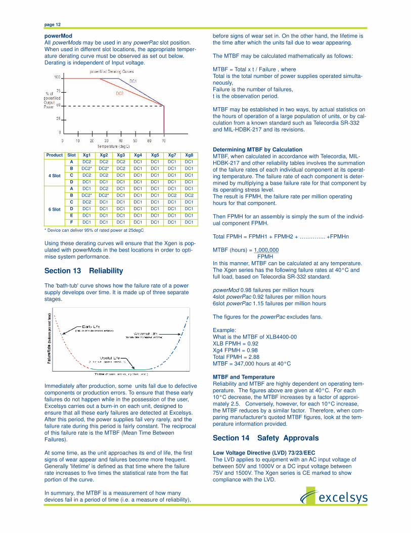
powerMod
All powerMods may be used in any powerPac slot position.
When used in different slot locations, the appropriate temper-
ature derating curve must be observed as set out below.
Derating is independent of Input voltage.
* Device can deliver 95% of rated power at 25degC
Using these derating curves will ensure that the Xgen is pop-
ulated with powerMods in the best locations in order to opti-
mise system performance.
Section 13 Reliability
The 'bath-tub' curve shows how the failure rate of a power
supply develops over time. It is made up of three separate
stages.
Immediately after production, some units fail due to defective
components or production errors. To ensure that these early
failures do not happen while in the possession of the user,
Excelsys carries out a burn-in on each unit, designed to
ensure that all these early failures are detected at Excelsys.
After this period, the power supplies fail very rarely, and the
failure rate during this period is fairly constant. The reciprocal
of this failure rate is the MTBF (Mean Time Between
Failures).
At some time, as the unit approaches its end of life, the first
signs of wear appear and failures become more frequent.
Generally 'lifetime' is defined as that time where the failure
rate increases to five times the statistical rate from the flat
portion of the curve.
In summary, the MTBF is a measurement of how many
devices fail in a period of time (i.e. a measure of reliability),
Product Slot Xg1 Xg2 Xg3 Xg4 Xg5 Xg7 Xg8
4 Slot
A DC2 DC2 DC2 DC1 DC1 DC1 DC1
B DC2* DC2* DC2 DC1 DC1 DC1 DC1
C DC2 DC2 DC1 DC1 DC1 DC1 DC1
D DC1 DC1 DC1 DC1 DC1 DC1 DC1
6 Slot
A DC1 DC2 DC1 DC1 DC1 DC1 DC1
B DC2* DC2* DC1 DC1 DC1 DC2 DC2
C DC2 DC1 DC1 DC1 DC1 DC1 DC1
D DC1 DC1 DC1 DC1 DC1 DC1 DC1
E DC1 DC1 DC1 DC1 DC1 DC1 DC1
F DC1 DC1 DC1 DC1 DC1 DC1 DC1

page 13
The relevant European Standard for Xcite, Xlite, Xhite, Xkite and
Xqite models is EN60950 (Information Technology).
The relevant European Standard for Xvite, Xmite, Xrite and Xzite
medical models is EN60601-1 (Medical Devices Directive).
With appropriate packaging, the Xgen can also meet the
requirements of EN61010-1 for industrial scientific measuring
equipment and process control.
The Xcite, Xlite, Xhite, Xkite and Xqite models are designed to
comply with the requirements of IEC950, EN60950,
UL1950, CSA 22.2 No. 234 and IEC 1010, when correctly
installed in a limited access environment.
The Xvite, Xmite, Xrite and Xzite models are designed to comply
with the requirements of IEC601-1, EN60601-1,
UL2601-1 and CSA601-1, for non-patient connect applica-
tions.
powerMods Xg2, Xg3, Xg4 and Xg5 are capable of providing
hazardous energy levels (>240 VA). Equipment manufactur-
ers must provide adequate protection to service personnel.
Environmental Parameters
The Xgen series is designed for the following parameters:
Material Group IIIb, Pollution Degree 2
Installation Category 2
Class I
Indoor use (installed, accessible to Service Engineers only).
Altitude: -155 metres to +2000 metres from sea level.
Humidity: 5 to 95% non-condensing.
Operating temperature -20°C to 70°C
Derate to 70°C. See powerPac Derating for details.
Approval Limitations
Use in North America
When this product is used on 180 to 253 Volts AC mains
with no neutral, connect the two live wires to L (live) and N
(neutral) terminals on the input connector.
Standard
Creepage Distances Xcite, Xlite, Xhite, Xkite Xqite models
Primary mains circuits to earth: 2.5mm spacing
Primary mains circuits to secondary: 5mm spacing
Dielectric strength Xcite, Xlite, Xhite, Xkite Xqite models
Primary mains circuits to chassis: 1500VAC
Primary mains circuits to secondary: 3000VAC
Medical
Creepage Distances Xvite, Xmite, Xrite, Xzite models
Primary mains circuits to earth: 4mm spacing
Primary mains circuits to secondary: 8mm spacing
Dielectric strength Xvite, Xmite, Xrite, Xzite models
Primary mains circuits to chassis: 1500VAC
Primary mains circuits to secondary: 4000VAC
The primary to secondary test is not possible with modules
fitted to the unit, as damage to the EMI capacitors will occur.
Output Isolation
Outputs are each isolated 500V DC to each other and 500
V DC to chassis.
Section 15 EMC
EMC Directive 89/336/EEC
Component Power Supplies such as the Xgen series are not
covered by the EMC directive. It is not possible for any
power supply manufacturer to guarantee conformity of the
final product to the EMC directive, since performance is criti-
cally dependent on the final system configuration.
System compliance with the EMC directive is facilitated by
Xgen compliance with several of the requirements as outlined
in the following paragraphs. Although the Xgen product
series meet these requirements, the CE mark does not cover
this area.
EMISSIONSPower Factor (Harmonic) CorrectionThe Xgen series incorporates active power factor correction
and therefore meets the requirements of EN61000-3-2.
Power factor: 0.98
EN61000-3-3 Flicker & Voltage Fluctuation Limits
Xgen power supplies meet the requirements of the limits on
voltage fluctuations and flicker in low voltage supply systems.
EN55022 Class B Conducted Emissions
Under appropriate test conditions, the Xgen series meets the
requirements of EN55022 Class B, without the need for exter-
nal filtering.
IMMUNITYThe Xgen series has been designed to meet, and tested to,
the immunity specifications outlined below:
EN61000-4-2 Electrostatic Discharge Immunity8kV Air discharge applied to Enclosure
6kV Contact with Enclosure
EN61000-4-3 Radiated Electromagnetic Field 10Volts/metre 80MHz to 2.5GHz applied to Enclosure
EN61000-4-4 Fast Transients-Burst Immunity
+/-2kV
EN61000-4-5 Input Surge Immunity
+/-2kV Common Mode 1.2/50 S (Voltage); 8/20uS (Current)
+/- 1kV Differential Mode 1.2/50 S (Voltage) 8/20 S (Current)
EN61000-4-6 Conducted Immunity
10 V/m 150KHz to 80MHz
EN61000-4-11 Voltage Dips
0% 1s Criteria B
40% 100ms Criteria B
70% 10ms Criteria A
Further details on all tests are available from Excelsys.
Guidelines for Optimum EMC PerformanceThe Xgen series is designed to comply with European
Normative limits (EN) for conducted and radiated when cor-
rectly installed in a system. See performance levels attained
above. However, power supply compliance with these limits is
not a guarantee of system compliance. System EMC perform-
ance can be impacted by a number and combination items.
Design consideration such as PCB layout and tracking,
cabling arrangements and orientation of the power supply
amongst others all directly contribute to the EMC perform-
ance of a system.

page 14
Cabling arrangements and PCB tracking layouts are the
greatest contributing factor to system EMC performance. It is
important that PCB tracks and power cables are arranged to
minimise current carrying loops that can radiate, and to min-
imise loops that could have noise currents induced into them.
All cables and PCB tracks should be treated as radiation
sources and antennae and every effort should be made to
minimise their interaction
a. Keep all cable lengths as short as possible.
b. Minimise the area of power carrying loops to min
imise radiation, by using twisted pairs of power
cables with the maximum twist possible..
c. Run PCB power tracks back to back.
d. Minimise noise current induced in signal carrying
lines, by twisted pairs for sense cables with the
maximum twist possible.
e. Do not combine power and sense cables in the
same harness
f. Ensure good system grounding. System Earth
should be a “starpoint”. Input earth of the equip
ment should be directed to the “starpoint” as soon
as possible. The power supply earth should be
connected directly to the “starpoint”. All other
earths should go to the ‘starpoint”
Section 16 Connectors
The pinout connections and diagrams of the Xgen power and
signal connectors are as follows
Output Connector PinoutPin J4 (type A) J4 (type B)
1 -Vout -V2
2 +Vout +V2
3 -V1
4 +V1
Type A, Xg1 -Xg7 Type B Xg8
J4 Mating Connectors:
Type A: M4 Screw Terminals
Type B: Camden p/n CTB9200/4A
Output Signals Connector Pinout
Pin J3 (Xg1 to Xg5 J3 (Xg7) J3 (Xg8)
1 +Sense not used -pg (V2)
2 -Sense not used +pg (V2)
3 Vtrim not used Inhibit (V2)
4 Itrm Common Common (V2)
5 +Inhibit/Enable -pg -pg (V1)
6 -Inhibit/Enable +pg +pg (V1)
7 +pg Inhibit Inhibit (V1)
8 -pg Common Common (V1)
J3 powerMod Signals Mating Connector:
Housing: Molex p/n 51110-0850 (Non Locking), 51110-0860
(Locking) or equivalent
Crimp Terminal: Molex p/n 50394
Input Connections powerPac
Input Connector and Signals Pinout J2 powerPac
Pin J1 J2
1 Line Common
2 Neutral +5V Bias
3 Earth not used
4 AC Fail
5 Fan Fail *
6 Global Enable
7 Temp Alarm*
8 Global Inhibit* Option 01
J1 Mating Connector:
IEC320 type female plug rated 13A
J2 Signals Mating Connector:
Housing: Molex p/n 51110-0850 (Non Locking), 51110-0860
(Locking) or equivalent
Crimp Terminal: Molex p/n 50394
Alternative Input Mains Connector.
Some applications may require a screw terminal input rather
than the standard IEC320 connector provided with the Xgen
(except XCE and XLD). For such applications, Excelsys can
offer the XE1, the IEC to Screw terminal adapter accessory
plug. This is a press fit connector that plugs securely into the
Xgen powerPac and provides the system integrator with screw
terminals for mains connection. See photos for correct insertion
of XE1.
J3
J4
Voltage
Adjust
M4 Screws
2 1
2
1
J3
J4
V1 Adjust
2 1
1
3
4
2
V2 Adjust

page 15
Dimensional drawingsCorrect pin positions are indented to assist connection
Pins are indented to indicate the correct connection
1.. Live (L)
2. Earth Centre (Earth)
3. Neutral (N)
4. Screw size M3.
Max Torque to be used on screws is 1.5Nm
For applications where spade terminal inputs are a required,
Excelsys recommend the use of the Schurter IEC Appliance
plug 4787. See picture and dimensional drawing. Further infor-
mation available from http://www.schurter.com
Section 17 Mechanical Drawings
See mechanical drawings for Xgen series overleaf.
Xgen Mounting Options
To ease system integration there are three methods of mount-
ing the Xgen in a system.
1. Base Plate mounting
The unit can be mounted in the system via the mounting holes
present on base of Xgen. See mechanical drawings for mount-
ing hole positions. Use M4 mounting screws. Ensure that maxi-
mum screw penetration from base does not exceed 6mm.
2. Flexmount system A
Using the side mounting clips accesory shown. The clip can be
positioned at the user defined position along the slide rail on
the side of the Xgen. The clip is then mounted to the system
base plate. Use M4 mounting screws to fix mounting clip to
system base. Excelsys part number Z165
3. Fleximount System 3
Using the slide rail on side of the Xgen, self clenching studs
can be placed at a user defined position.
PEM part number: FH-M4-X or FH-832-X (X=stud length).
See PEM website for further details http://www.pemnet.com

page 16
J1
J2
IN
PU
T A
C 1
00
V-2
40
V 5
0/6
0H
z
SE
E IN
ST
RU
CT
ION
MA
NU
AL
70
C M
AX
OP
ER
AT
ING
TE
MP
ER
AT
UR
E
29.50 40.40
122.0046.00
23.50
23.50
80.00
92.00
19.00
19.00 127.00
SLOT
SLOT
SLOT
SLOT
SLOT
SLOT
19.00
Third angle projection
TOP VIEW
All dimensions in mm.
Mounting Holes
4 M4 threaded holes on Base. Max screw penetration is 6mm from Base.
Fleximount Side Mounting Slots
Use with self-clinching studs type FH-M4-X or FH-832-X (X= stud length) from PEM, or equivalent
Alternatively, use Xgen Side Clamps from Excelsys. Part No. Z165 (drawing 61401)
50.00 97.75
All dimensions in mm.
Mounting Holes
4 M4 threaded holes on Base. Max screw penetration is 6mm from Base.
J1
J2
IN
PU
T A
C 1
00
V-2
40
V 5
0/6
0H
z
SE
E IN
ST
RU
CT
ION
MA
NU
AL
70
C M
AX
OP
ER
AT
ING
TE
MP
ER
AT
UR
E
29.50 40.40
122.0046.00
23.50
23.50
42.00
92.00
19.00 89.00
SLOT D
SLOT C
SLOT B
SLOT A
Third angle projection
TOP VIEW
50.00 97.75
Xlite, Xmite, Xkite, Xrite,
Xcite, Xvite, Xqite, Xzite, Xhite
(except XCE and XVE)

page 17
J1
J2
IN
PU
T A
C 1
00
V-2
40
V 5
0/6
0H
z
SE
E IN
ST
RU
CT
ION
MA
NU
AL
70
C M
AX
OP
ER
AT
ING
TE
MP
ER
AT
UR
E
29.50 40.40
122.00
23.50
23.50
80.00
92.00
19.00
19.00 127.00
SLOT F
SLOT E
SLOT D
SLOT C
SLOT B
SLOT A
19.00
Third angle projection
TOP VIEW
All dimensions in mm.
Mounting Holes
4 M4 threaded holes on Base. Max screw penetration is 6mm from Base.
Fleximount Side Mounting Slots
Use with self-clinching studs type FH-M4-X or FH-832-X (X= stud length) from PEM, or equivalent
Alternatively, use Xgen Side Clamps from Excelsys. Part No. Z165 (drawing 61401)
54.00 97.75
XCE and XVE

page 18
Section 18 Configuring XgenWhen configuring your Xgen, it is important to observe the
power ratings of individual powerMods, powerPacs in order to
ensure the best performance of the Xgen in the system.
Operating ambient temperature around the power supply and
Input voltage can impact the performance of a power supply
in a system. The examples set out below illustrate the flexibili-
ty of the Xgen for many applications, whilst also providing the
optimum solution for system designers.
Our Sales and Applications team will be delighted to assist
you in defining the best power supply for your application.
You can also use the eXcelete wizard, the online configurator
at http://www.excelsys.com
Example 1.
Max
Ambient
temp: 25°C
Input volt-
age: 90-264VAC
Medically approved (EN60601-1)
1. Select powerMods
Output 1: 24V@25A 3 x Xg4 connected in parallel
Output 2: 12V@12A Xg3
Output 3: 5V@4A Xg7
Output 4: 15V@2A V1 of Xg8, Adjust to 15V
Output 5: -15V@2A V2 of Xg8,. Adjust to 15V
2. Calculate the power required
Power = Volt x Current
Output 1: 600W
Output 2: 144W
Output 3: 20W
Output 4: 30W
Output 5: 30W Total: 824W
3. Select powerPac
824W at 90VAC in at 25°C, and carry medical approvals
XVC: 1000W medically approved powerPac (Xvite) delivers
850W at 85VAC.
(Refer to powerPac derating curves Section 12.
4. Select powerMod slot position
Refer to powerMod derating curve Section 12.
At 25°C all powerMods can be configured in any slot position.
5. Define part number
All powerMods are within their ratings in all slot positions.
XVC444780
Example 2
Max ambient
temp: 40°C
Input voltage: 90-264VAC
Low acoustic noise
Standard safety approvals (EN60950)
1. Select powerMods
Output 1: 24V@15A 2 x Xg4 connected in parallel
Output 2: 5V@30A Xg2
Output 3: 12V@15A Xg3
Output 4: [email protected] V1 of Xg8,
Output 5: [email protected] V2 of Xg8,. Adjust to 18V
2. Calculate the power required
Power = Volt x Current
Output 1: 360W
Output 2: 150W
Output 3: 180W
Output 4: 36W
Output 5: 29W Total: 756W
3. Select powerPac
756W at 90VAC in at 40°C, and low noise
XQB: 900W low noise powerPac (Xqite) delivers 850W at
85VAC
(Refer to powerPac derating curves Section 12.
4. Select powerMod slot position
Refer to powerMod derating curve Section 12.
At 40°C, Xg4 delivers 240W in all slot positions
At 40°C Xg2 delivers 167W in slot A, 160W Slot B, 200W in
Slots C, D, E and F
At 40°C, Xg3 delivers 240W in all slot positions.
powerMods can be configured in any slot position.
At 40°C, Xg8 delivers 80W in slot B, 96W in Slots A,C,D,E,F
5. Define part number
All
powerMods
are within
their ratings
in all slot positions
XQB234480-00
Example 3Max ambient temp: 40°C
Input Voltage: 200-240VAC
Standard Approvals: (EN60950)
1. Select powerMods
Output 1: 24V@60A 6 x Xg4 connected in parallel
Output 2: 12V@30A 2 x Xg3 connected in parallel
Output 3: 3.3V@30A Xg2, Adjust to 3.3V
Output 4: 12V@8A Xg3
Output 5: 12V@8A Xg3
2. Calculate the power required
Power = Volt x Current
Output 1: 1440W
Output 2: 360W
Output 3: 99W
Output 4: 96W
Output 5: 96W Total: 2091W
3. Select powerPac
2091W at 200VAC in at 40°C, and carry standard approvals
XCD: 1200W powerPac (Xvite) delivers 1200W at 200VAC.
(Refer to powerPac derating curves Section 12.
Requires an XCD and XCC powerPac to achieve 2091W.
Output 1 Output 2 Output 3 Output 4 Output 5
Volts 24V 12V 3.3V 12V 12V
Amps 60A 30A 30A 8A 8A
Output 1 Output 2 Output 3 Output 4 Output 5
Volts 24V 12V 5V 15V -15V
Amps 25A 12A 4A 2A 2A
Output 1 Output 2 Output 3 Output 4 Output 5
Volts 24V 5V 12V 24V 18V
Amps 15A 30A 15A 1.5A 1.5A

4. Select powerMod slot position
Refer to powerMod derating curve Section 12.
At 40°C, Xg4 delivers 240W in all slot positions
At 40°C, Xg3 delivers 240W in all slot positions.
powerMods can be configured in any slot position.
At 40°C Xg2 delivers 167W in slot A, 160W Slot B, 200W in
Slots C, D, E and F
5. Define part number
All powerMods are within their ratings in all slot positions.
Divide the power consumption over the two powerPacs
ensuring that no powerPac exceed its power rating.
XCC233444 to deliver 3.3V@30A, 12V@30A, 24V@30A
XCC444330 to deliver 24V@30A, 12V@8, 12V@8A
Parallel connect modules over two powerPacs using the
same method as outlined in Section 7.
Contact Details
Excelsys Technologies has an international network of distrib-
utors and representatives. All contact details can be found at
http://www.excelsys.com
You can also contact us directly
EuropeExcelsys Technologies Limited
Tel: +353 21 4354716
Fax: +353 21 4354864
email:[email protected]
27 Eastgate Drive
Eastgate Business Park
Little Island,
Co.Cork, Ireland
North America
Excelsys Technologies
Tel: +1 972 771 4544
Fax: +1 972 421 1805
email:[email protected]
519 Intestate 30, #309
Rockwall
TX 75087, USA
Whilst every effort has been made to ensure the accuracy of the contents
of this handbook, Excelsys Technologies Ltd. cannot accept any liabilityfor errors contained herein. Excelsys operates a policy of Continuous
Product Improvement, and specifications are subject to change withoutprior notice.
Rev L 28 July 2011


![Draft 35 Ultimod XGen Xb28 FEB 2012[1] - dicel.fr](https://static.fdocuments.us/doc/165x107/62a08a41c9f7476c93094f64/draft-35-ultimod-xgen-xb28-feb-20121-dicelfr.jpg)