XCubeSAN SANOS 4.0 User s Manual...XCubeSAN SANOS 4.0 User’s Manual Applicable Models: XS5224D,...
402
XCubeSAN SANOS 4.0 User’s Manual Applicable Models: XS5224D, XS5216D, XS5212D, XS5212S, XS5226D, XS5226S XS3224D, XS3224S, XS3216D, XS3216S, XS3212D, XS3212S XS3226D, XS3226S, XS1224D, XS1224S, XS1216D, XS1216S XS1212D, XS1212S, XS1226D, XS1226S QSAN Technology, Inc. www.QSAN.com
Transcript of XCubeSAN SANOS 4.0 User s Manual...XCubeSAN SANOS 4.0 User’s Manual Applicable Models: XS5224D,...

XCubeSAN SANOS 4.0 User’s Manual
Applicable Models: XS5224D, XS5216D, XS5212D, XS5212S, XS5226D, XS5226S XS3224D, XS3224S, XS3216D, XS3216S, XS3212D, XS3212S XS3226D, XS3226S, XS1224D, XS1224S, XS1216D, XS1216S
XS1212D, XS1212S, XS1226D, XS1226S
QSAN Technology, Inc. www.QSAN.com
Copyright © Copyright 2018 QSAN Technology, Inc. All rights reserved. No part of this document may be reproduced or transmitted without written permission from QSAN Technology, Inc. March 2018 This edition applies to QSAN XCubeSAN SANOS (SAN Operating System) 4.0. QSAN believes the information in this publication is accurate as of its publication date. The information is subject to change without notice. Trademarks QSAN, the QSAN logo, XCubeSAN, and QSAN.com are trademarks or registered trademarks of QSAN Technology, Inc. Microsoft, Windows, Windows Server, and Hyper-V are trademarks or registered trademarks of Microsoft Corporation in the United States and/or other countries. Linux is a trademark of Linus Torvalds in the United States and/or other countries. UNIX is a registered trademark of The Open Group in the United States and other countries. Mac and OS X are trademarks of Apple Inc., registered in the U.S. and other countries. Java and all Java-based trademarks and logos are trademarks or registered trademarks of Oracle and/or its affiliates. VMware, ESXi, and vSphere are registered trademarks or trademarks of VMware, Inc. in the United States and/or other countries. Citrix and Xen are registered trademarks or trademarks of Citrix Systems, Inc. in the United States and/or other countries. Other trademarks and trade names used in this document to refer to either the entities claiming the marks and names or their products are the property of their respective owners.

Notices i
Notices
This XCubeSAN SANOS 4.0 user’s manual is applicable to the following XCubeSAN models:
XCubeSAN Storage System 4U 19” Rack Mount Models
Model Name Controller Type Form Factor, Bay Count, and Rack Unit
XS5224D Dual Controller LFF 24-disk 4U Chassis
XS3224D Dual Controller LFF 24-disk 4U Chassis
XS3224S Single Controller LFF 24-disk 4U Chassis
XS1224D Dual Controller LFF 24-disk 4U Chassis
XS1224S Single Controller LFF 24-disk 4U Chassis
XCubeSAN Storage System 3U 19” Rack Mount Models
Model Name Controller Type Form Factor, Bay Count, and Rack Unit
XS5216D Dual Controller LFF 16-disk 3U Chassis
XS3216D Dual Controller LFF 16-disk 3U Chassis
XS3216S Single Controller LFF 16-disk 3U Chassis
XS1216D Dual Controller LFF 16-disk 3U Chassis
XS1216S Single Controller LFF 16-disk 3U Chassis
XCubeSAN Storage System 2U 19” Rack Mount Models
Model Name Controller Type Form Factor, Bay Count, and Rack Unit
XS5212D Dual Controller LFF 12-disk 2U Chassis
XS5212S Single Controller LFF 12-disk 2U Chassis
XS3212D Dual Controller LFF 12-disk 2U Chassis
XS3212S Single Controller LFF 12-disk 2U Chassis
XS1212D Dual Controller LFF 12-disk 2U Chassis
XS1212S Single Controller LFF 12-disk 2U Chassis
XS5226D Dual Controller SFF 26-disk 2U Chassis
XS5226S Single Controller SFF 26-disk 2U Chassis
XS3226D Dual Controller SFF 26-disk 2U Chassis
XS3226S Single Controller SFF 26-disk 2U Chassis
XS1226D Dual Controller SFF 26-disk 2U Chassis
ii © Copyright 2018 QSAN Technology, Inc. All Right Reserved.
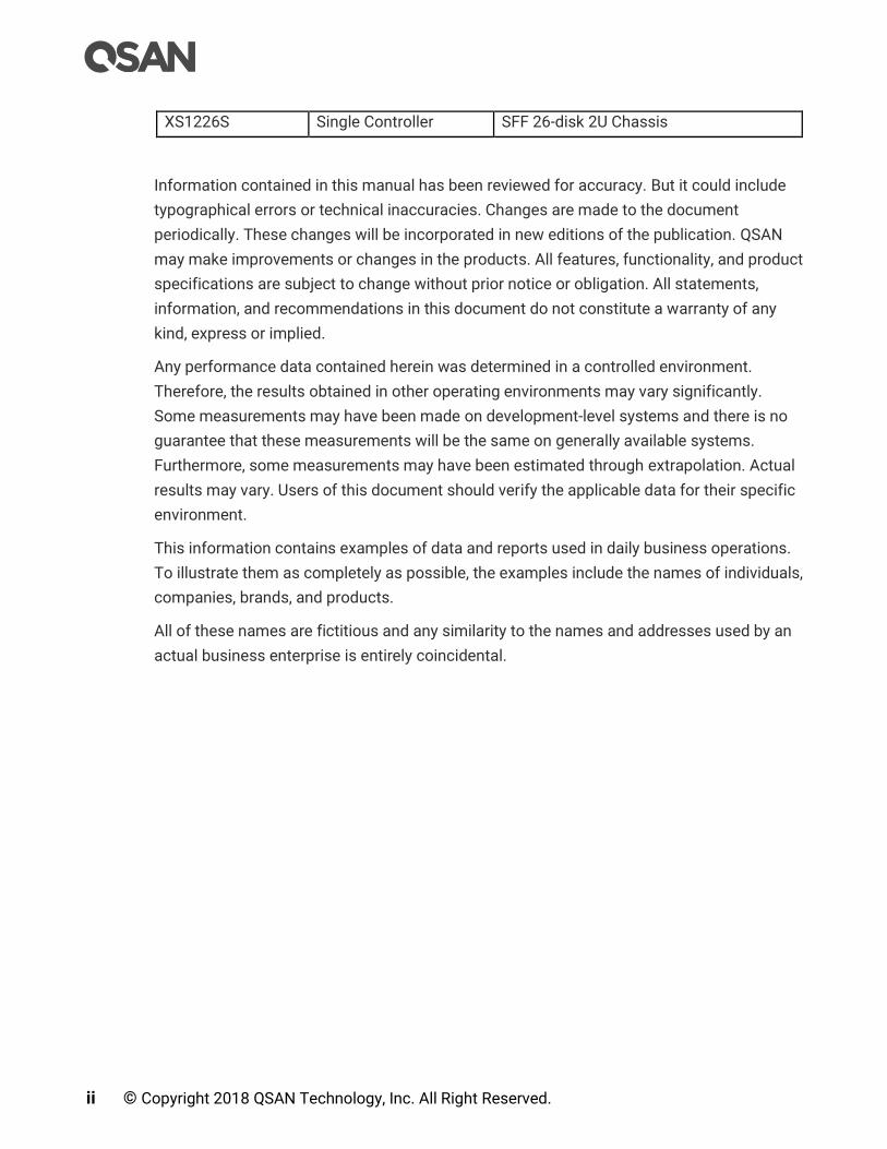
XS1226S Single Controller SFF 26-disk 2U Chassis
Information contained in this manual has been reviewed for accuracy. But it could include
typographical errors or technical inaccuracies. Changes are made to the document
periodically. These changes will be incorporated in new editions of the publication. QSAN
may make improvements or changes in the products. All features, functionality, and product
specifications are subject to change without prior notice or obligation. All statements,
information, and recommendations in this document do not constitute a warranty of any
kind, express or implied.
Any performance data contained herein was determined in a controlled environment.
Therefore, the results obtained in other operating environments may vary significantly.
Some measurements may have been made on development-level systems and there is no
guarantee that these measurements will be the same on generally available systems.
Furthermore, some measurements may have been estimated through extrapolation. Actual
results may vary. Users of this document should verify the applicable data for their specific
environment.
This information contains examples of data and reports used in daily business operations.
To illustrate them as completely as possible, the examples include the names of individuals,
companies, brands, and products.
All of these names are fictitious and any similarity to the names and addresses used by an
actual business enterprise is entirely coincidental.

Contents iii
Table of Contents
Notices ............................................................................................................................ i
Preface .......................................................................................................................... xx
About This Manual ......................................................................................................................... xx
Related Documents ........................................................................................................................ xx
Technical Support .......................................................................................................................... xx
Information, Tip and Caution ........................................................................................................ xxi
Conventions ................................................................................................................................... xxi
1. SANOS Overview ..................................................................................................... 1
1.1. Introduction to SANOS ....................................................................................................... 1
1.1.1. SANOS System Architecture ............................................................................... 1
1.1.2. SANOS Storage Pool Architecture ...................................................................... 3
1.1.3. SANOS 4.0 Functionality List .............................................................................. 4
1.2. Terminology ........................................................................................................................ 6
2. Prepare for Installation ........................................................................................... 9
2.1. Prepare for Configuration Planning ................................................................................... 9
2.1.1. Configuration Planning for Initial Setup ........................................................... 15
2.1.2. Management IP Configuration Planning .......................................................... 16
2.1.3. Notification Configuration Planning ................................................................. 16
2.1.4. iSCSI Configuration Planning ............................................................................ 17
2.1.5. Fibre Channel Configuration Planning .............................................................. 18
2.1.6. Storage Configuration Planning ........................................................................ 19
2.1.7. Backup Configuration Planning......................................................................... 21
2.2. System Parameters .......................................................................................................... 22
2.3. Configuration Example ..................................................................................................... 25
3. Getting Started ...................................................................................................... 32
3.1. Power on the Storage System .......................................................................................... 32
3.2. Discover the SAN Storage System .................................................................................. 32
3.2.1. QFinder Utility ..................................................................................................... 32
3.3. Initial Setup ........................................................................................................................ 34
4. SANOS User Interface ........................................................................................... 39
4.1. Accessing the Management Web UI ............................................................................... 39
4.2. SANOS 4.0 Desktop Panel ................................................................................................ 40
4.3. Function Menus ................................................................................................................ 41
4.3.1. Dashboard Menu ................................................................................................ 42
iv © Copyright 2018 QSAN Technology, Inc. All Right Reserved.
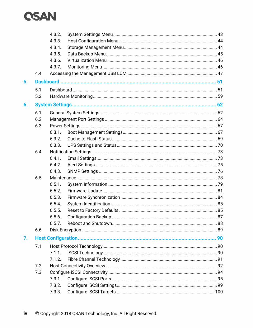
4.3.2. System Settings Menu ....................................................................................... 43
4.3.3. Host Configuration Menu .................................................................................. 44
4.3.4. Storage Management Menu .............................................................................. 44
4.3.5. Data Backup Menu ............................................................................................. 45
4.3.6. Virtualization Menu ............................................................................................ 46
4.3.7. Monitoring Menu ................................................................................................ 46
4.4. Accessing the Management USB LCM ........................................................................... 47
5. Dashboard ............................................................................................................ 51
5.1. Dashboard ......................................................................................................................... 51
5.2. Hardware Monitoring ........................................................................................................ 59
6. System Settings .................................................................................................... 62
6.1. General System Settings .................................................................................................. 62
6.2. Management Port Settings .............................................................................................. 64
6.3. Power Settings .................................................................................................................. 67
6.3.1. Boot Management Settings ............................................................................... 67
6.3.2. Cache to Flash Status ........................................................................................ 69
6.3.3. UPS Settings and Status .................................................................................... 70
6.4. Notification Settings ......................................................................................................... 73
6.4.1. Email Settings ..................................................................................................... 73
6.4.2. Alert Settings ...................................................................................................... 75
6.4.3. SNMP Settings ................................................................................................... 76
6.5. Maintenance ...................................................................................................................... 78
6.5.1. System Information ........................................................................................... 79
6.5.2. Firmware Update ................................................................................................ 81
6.5.3. Firmware Synchronization ................................................................................. 84
6.5.4. System Identification ......................................................................................... 85
6.5.5. Reset to Factory Defaults .................................................................................. 85
6.5.6. Configuration Backup ........................................................................................ 87
6.5.7. Reboot and Shutdown ........................................................................................ 88
6.6. Disk Encryption ................................................................................................................. 89
7. Host Configuration ................................................................................................ 90
7.1. Host Protocol Technology................................................................................................ 90
7.1.1. iSCSI Technology ............................................................................................... 90
7.1.2. Fibre Channel Technology ................................................................................. 91
7.2. Host Connectivity Overview ............................................................................................. 92
7.3. Configure iSCSI Connectivity ........................................................................................... 94
7.3.1. Configure iSCSI Ports ........................................................................................ 95
7.3.2. Configure iSCSI Settings.................................................................................... 99
7.3.3. Configure iSCSI Targets .................................................................................. 100
Contents v
7.3.4. Configure iSCSI CHAP Accounts .................................................................... 104
7.3.5. Active Sessions ................................................................................................ 107
7.4. Configure Fibre Channel Connectivity ........................................................................... 108
7.4.1. Configure Fibre Channel Link Speed ............................................................... 109
7.4.2. Configure Fibre Channel Topology ................................................................. 110
7.4.3. Configure Fibre Channel Targets .................................................................... 111
7.4.4. Clear Fibre Channel Counters .......................................................................... 111
8. Storage Management .......................................................................................... 113
8.1. RAID Technology ............................................................................................................. 113
8.1.1. Traditional RAID Overview ............................................................................... 113
8.1.2. RAID EE Overview ............................................................................................. 119
8.1.3. Theory of RAID EE Operation ........................................................................... 120
8.2. SANOS Storage Architecture ......................................................................................... 124
8.2.1. Pool Technology ............................................................................................... 124
8.2.2. Migrate vs. Add Disk Group ............................................................................. 126
8.2.3. Volume Technology ......................................................................................... 127
8.2.4. LUN Technology ............................................................................................... 128
8.2.5. Hot Spares ........................................................................................................ 129
8.3. Working with Disk Drives ................................................................................................ 131
8.3.1. List Disks .......................................................................................................... 131
8.3.2. Operations on Disks ......................................................................................... 134
8.3.3. S.M.A.R.T. ......................................................................................................... 137
8.4. Configure Thick Provisioning Pools .............................................................................. 140
8.4.1. Create a Thick Provisioning Pool .................................................................... 140
8.4.2. List Thick Provisioning Pools .......................................................................... 146
8.4.3. Operations on Thick Provisioning Pools ........................................................ 148
8.4.4. Migrate a Disk Group in a Thick Provisioning Pool........................................ 151
8.4.5. Add a Disk Group in a Thick Provisioning Pool .............................................. 155
8.5. Configuring Volumes ...................................................................................................... 157
8.5.1. Create a Volume ............................................................................................... 158
8.5.2. List Volumes ..................................................................................................... 161
8.5.3. Operations on Volumes ................................................................................... 162
8.5.4. Extend Volume Capacity .................................................................................. 167
8.5.5. Fast RAID Rebuild ............................................................................................. 168
8.6. Configure LUN Mappings ............................................................................................... 170
8.6.1. Map a LUN of iSCSI Connectivity .................................................................... 170
8.6.2. Map a LUN of Fibre Channel Connectivity ...................................................... 171
8.6.3. List LUN Mappings ........................................................................................... 172
8.6.4. Operations on LUN Mappings ......................................................................... 173
8.7. Connect by Host Initiator ................................................................................................ 173

vi © Copyright 2018 QSAN Technology, Inc. All Right Reserved.
8.8. Disk Roaming .................................................................................................................. 174
9. Thin Provisioning ................................................................................................ 175
9.1. Overview .......................................................................................................................... 175
9.1.1. Thick Provisioning vs. Thin Provisioning ........................................................ 176
9.2. Theory of Operation ........................................................................................................ 177
9.2.1. Thin Provisioning Architecture ........................................................................ 177
9.2.2. Space Reclamation .......................................................................................... 178
9.2.3. Thin Provisioning Policies ............................................................................... 179
9.3. Configure Thin Provisioning Pools ................................................................................ 179
9.3.1. Create a Thin Provisioning Pool ...................................................................... 180
9.3.2. List Thin Provisioning Pools ............................................................................ 186
9.3.3. Operations on Thin Provisioning Pools .......................................................... 188
9.3.4. Add a Disk Group in a Thin Provisioning Pool ................................................ 191
9.4. Configure Volumes ......................................................................................................... 194
9.4.1. Create a Volume in a Thin Provisioning Pool ................................................. 194
9.4.2. List Volumes and Operations on Volumes ..................................................... 198
9.5. Configure LUN Mappings and Connect by Host Initiator ............................................. 199
10. SSD Cache .......................................................................................................... 200
10.1. Overview .......................................................................................................................... 200
10.2. Theory of Operation ........................................................................................................ 202
10.2.1. System Memory and SSD Cache Capacity ..................................................... 202
10.2.2. SSD Cache Pool Architecture .......................................................................... 203
10.2.3. RAID Level of SSD Cache Pool ........................................................................ 205
10.2.4. Read/Write Cache Cases ................................................................................. 207
10.2.5. Populating the Cache ....................................................................................... 211
10.2.6. SSD Cache Tuning ............................................................................................ 212
10.3. Configure SSD Cache ..................................................................................................... 214
10.3.1. Enable SSD Cache License .............................................................................. 214
10.3.2. Create an SSD Cache Pool .............................................................................. 215
10.3.3. List SSD Cache Pools....................................................................................... 218
10.3.4. Operations on SSD Cache Pools ..................................................................... 221
10.4. Monitor SSD Cache Statistics ........................................................................................ 223
10.5. SSD Cache Notices ......................................................................................................... 226
11. Auto Tiering ........................................................................................................ 227
11.1. Overview .......................................................................................................................... 227
11.1.1. Tier Categories ................................................................................................. 228
11.1.2. Flexible RAID and Disk Configurations ........................................................... 230
11.2. Theory of Operation ........................................................................................................ 230
11.2.1. Auto Tiering Architecture ................................................................................. 231
Contents vii
11.2.2. Intelligent Auto Tiering Mechanism ................................................................ 233
11.2.3. Tiering Policies ................................................................................................. 234
11.3. Configure Auto Tiering Pools ......................................................................................... 236
11.3.1. Enable Auto Tiering License ............................................................................ 237
11.3.2. Create an Auto Tiering Pool ............................................................................ 237
11.3.3. List Auto Tiering Pools..................................................................................... 243
11.3.4. Operations on Auto Tiering Pools ................................................................... 247
11.3.5. Add a Tier (Disk Group) in an Auto Tiering Pool ............................................ 248
11.3.6. Hot Spares in an Auto Tiering Pool ................................................................. 251
11.4. Configure Volumes ......................................................................................................... 251
11.4.1. Create a Volume in an Auto Tiering Pool ....................................................... 251
11.4.2. List Volumes and Operations on Volumes ..................................................... 255
11.5. Configure LUN Mappings and Connect by Host Initiator ............................................. 256
11.6. Transfer to Auto Tiering Pool ......................................................................................... 256
11.6.1. Transfer from Thick Provisioning Pool to Auto Tiering ................................. 258
11.6.2. Transfer from Thin Provisioning Pool to Auto Tiering ................................... 260
11.7. SSD Cache vs. Auto Tiering ............................................................................................ 263
12. Data Backup ........................................................................................................ 265
12.1. Managing Snapshots ...................................................................................................... 265
12.1.1. Theory of Operation ......................................................................................... 265
12.1.2. Configure Snapshot ......................................................................................... 268
12.1.3. Configure Rollback Snapshot .......................................................................... 272
12.1.4. Configure Schedule Snapshots ....................................................................... 273
12.1.5. Snapshot Notices ............................................................................................. 274
12.2. Managing Local Clones .................................................................................................. 276
12.2.1. Theory of Operation ......................................................................................... 277
12.2.2. Configure Local Clone ..................................................................................... 279
12.2.3. Configure Schedule Local Clone Tasks .......................................................... 282
12.2.4. Local Cloning Options ...................................................................................... 283
12.2.5. Local Clone Notices ......................................................................................... 284
12.3. Managing Remote Replications ..................................................................................... 284
12.3.1. Remote Replication Topologies ...................................................................... 285
12.3.2. Theory of Operation ......................................................................................... 288
12.3.3. Configure Remote Replication ........................................................................ 290
12.3.4. Configure Traffic Shaping ............................................................................... 296
12.3.5. Configure Schedule Remote Replication Tasks ............................................. 298
12.3.6. Replication Options .......................................................................................... 299
12.3.7. Configure MPIO in Remote Replication Task ................................................. 300
12.3.8. Configure MC/S in Remote Replication Task Path ........................................ 306
12.3.9. Local Clone Transfers to Remote Replication ............................................... 309

viii © Copyright 2018 QSAN Technology, Inc. All Right Reserved.
13. Monitoring .......................................................................................................... 315
13.1. Log Center ....................................................................................................................... 315
13.1.1. Operations on Event Logs ............................................................................... 316
13.2. Monitoring Enclosures .................................................................................................... 317
13.2.1. Hardware Monitoring ....................................................................................... 317
13.2.2. Configuring SES ................................................................................................ 319
13.3. Performance Monitoring ................................................................................................ 321
13.3.1. Disk Performance Monitoring ......................................................................... 321
13.3.2. Volume Performance Monitoring.................................................................... 322
13.3.3. iSCSI Port Performance Monitoring ............................................................... 324
13.3.4. Fibre Channel Port Monitoring ........................................................................ 324
14. SED and ISE Support ........................................................................................... 325
14.1. Overview .......................................................................................................................... 325
14.2. Theory of Operation ........................................................................................................ 327
14.2.1. SED Operation Process .................................................................................... 327
14.2.2. ISE Technology ................................................................................................. 329
14.3. Configure Authentication Key ........................................................................................ 331
14.3.1. Operations on Authentication Key .................................................................. 331
14.4. Configure SEDs ............................................................................................................... 336
14.4.1. List SEDs ........................................................................................................... 337
14.4.2. Operations on SEDs ......................................................................................... 339
14.5. Configure SED Pools ....................................................................................................... 343
14.5.1. Create an SED Pool .......................................................................................... 344
14.5.2. List SED Pools .................................................................................................. 349
14.5.3. Operations on SED Pools ................................................................................. 351
Rebuild on SED Pools ..................................................................................................... 352
Create an SSD Cache Pool on SED Pools ..................................................................... 352
Data Backup on Encrypted Volumes ............................................................................. 352
14.6. Configure ISE Drives ....................................................................................................... 353
14.6.1. List ISE Drives ................................................................................................... 353
14.6.2. Operations on ISE Drives ................................................................................. 355
15. Troubleshooting .................................................................................................. 358
15.1. Fault Isolation Methodology .......................................................................................... 358
15.1.1. Basic Steps ....................................................................................................... 358
15.1.2. Stopping I/O ...................................................................................................... 358
15.1.3. Diagnostic Steps .............................................................................................. 359
15.2. Rebuild ............................................................................................................................. 359
15.3. Volume Restoration ........................................................................................................ 362
15.3.1. Configure Volume Restoration ........................................................................ 364
Contents ix
16. Support and Other Resources.............................................................................. 365
16.1. Getting Technical Support .............................................................................................. 365
16.2. Online Customer Support ............................................................................................... 367
16.3. Accessing Product Updates ........................................................................................... 371
16.4. Documentation Feedback .............................................................................................. 372
Appendix ..................................................................................................................... 373
Glossary and Acronym List ......................................................................................................... 373
End-User License Agreement (EULA) ........................................................................................ 376

x © Copyright 2018 QSAN Technology, Inc. All Right Reserved.
Figures
Figure 1-1 SANOS System Architecture ............................................................................................ 1
Figure 1-2 SANOS System Architecture with Single Controller Configuration .............................. 2
Figure 1-3 SANOS Storage Pool Architecture .................................................................................. 3
Figure 1-4 SANOS 4.0 Desktop Panel ............................................................................................... 4
Figure 2-1 Dual-controller Topology ................................................................................................ 17
Figure 3-1 QFinder Utility ................................................................................................................. 33
Figure 3-2 Login Page of web UI ..................................................................................................... 34
Figure 3-3 Initial Configuration Step 1 ............................................................................................ 35
Figure 3-4 Initial Configuration Step 2 ............................................................................................ 36
Figure 3-5 Initial Configuration Step 3 ............................................................................................ 38
Figure 4-1 Login Page of web UI ..................................................................................................... 39
Figure 4-2 SANOS 4.0 Desktop Panel ............................................................................................. 40
Figure 4-3 Portable USB LCM .......................................................................................................... 47
Figure 4-4 USB LCM Screen ............................................................................................................. 47
Figure 5-1 Dashboard Function Submenu ...................................................................................... 51
Figure 5-2 Dashboard ....................................................................................................................... 51
Figure 5-3 System Information Block in the Dashboard ................................................................ 52
Figure 5-4 System Information Popup Window ............................................................................. 53
Figure 5-5 System View Block in the Dashboard ........................................................................... 54
Figure 5-6 Pool Information Popup Window .................................................................................. 55
Figure 5-7 Performance Block in the Dashboard ........................................................................... 58
Figure 5-8 Event Logs in the Dashboard ......................................................................................... 58
Figure 5-9 Hardware Monitoring Function Submenu..................................................................... 59
Figure 5-10 Hardware Monitoring ..................................................................................................... 60
Figure 5-11 Head Unit Popup Window .............................................................................................. 61
Figure 6-1 General Function Submenu ........................................................................................... 62
Figure 6-2 General Settings ............................................................................................................. 63
Figure 6-3 Management Port Function Submenu .......................................................................... 64
Figure 6-4 Management Port settings ............................................................................................ 65
Figure 6-5 Power Settings Function Submenu ............................................................................... 67
Figure 6-6 Boot Management Settings ........................................................................................... 67
Figure 6-7 Cache to Flash ................................................................................................................ 69
Figure 6-8 UPS Status and Settings ................................................................................................ 71
Figure 6-9 Notifications Function Submenu ................................................................................... 73
Figure 6-10 Email Settings ................................................................................................................. 74
Figure 6-11 Alert Settings .................................................................................................................. 75
Figure 6-12 SNMP Settings ................................................................................................................ 77
Contents xi
Figure 6-13 Maintenance Function Submenu .................................................................................. 79
Figure 6-14 System Information ........................................................................................................ 80
Figure 6-15 Firmware Update ............................................................................................................ 82
Figure 6-16 Enable Licenses .............................................................................................................. 83
Figure 6-17 Both Firmware Versions are Synchronized .................................................................. 84
Figure 6-18 Turn on the UID (Unique Identifier) LED ........................................................................ 85
Figure 6-19 Reset to Defaults ............................................................................................................ 86
Figure 6-20 Configuration Backup..................................................................................................... 88
Figure 6-21 Reboot and Shutdown .................................................................................................... 89
Figure 6-22 Reboot Options ............................................................................................................... 89
Figure 6-23 Disk Encryption Function Submenu .............................................................................. 89
Figure 7-1 Overview Function Submenu ......................................................................................... 92
Figure 7-2 Host Port Overview ......................................................................................................... 93
Figure 7-3 iSCSI Ports Function Submenu ..................................................................................... 95
Figure 7-4 List iSCSI Ports ............................................................................................................... 95
Figure 7-5 iSCSI IP Address Settings .............................................................................................. 96
Figure 7-6 Set Link Aggregation ...................................................................................................... 97
Figure 7-7 Set VLAN ID ..................................................................................................................... 98
Figure 7-8 Set Jumbo Frame ........................................................................................................... 98
Figure 7-9 Ping Host ......................................................................................................................... 99
Figure 7-10 Entity Name and iSNS Settings ................................................................................... 100
Figure 7-11 iSCSI Targets ................................................................................................................ 101
Figure 7-12 Authentication Method ................................................................................................ 102
Figure 7-13 Change Target Name ................................................................................................... 103
Figure 7-14 Change Network Portal ................................................................................................ 103
Figure 7-15 Change Alias ................................................................................................................. 104
Figure 7-16 Create a CHAP User ..................................................................................................... 105
Figure 7-17 List CHAP Users ........................................................................................................... 106
Figure 7-18 Modify a CHAP User ..................................................................................................... 106
Figure 7-19 Active Sessions ............................................................................................................ 107
Figure 7-20 Fibre Channel Ports Function Submenu ..................................................................... 108
Figure 7-21 List Fibre Channel Ports ............................................................................................... 109
Figure 7-22 Change Link Speed ....................................................................................................... 109
Figure 7-23 Change Topology.......................................................................................................... 110
Figure 7-24 Target Configuration .................................................................................................... 111
Figure 8-1 Data Block Distributed of RAID 5EE ............................................................................ 121
Figure 8-2 Disk 2 is Failed .............................................................................................................. 122
Figure 8-3 Empty Blocks are Rebuilt from the Failed Disk Drive ................................................. 122
Figure 8-4 Data is copied back ...................................................................................................... 123
Figure 8-5 Data Block Distributed of RAID 60EE .......................................................................... 123
Figure 8-6 Storage Architecture of Thick Provisioning Pool ....................................................... 125
xii © Copyright 2018 QSAN Technology, Inc. All Right Reserved.
Figure 8-7 Volume in Storage Architecture .................................................................................. 127
Figure 8-8 LUM Mappings in Storage Architecture ...................................................................... 129
Figure 8-9 Hot Spares .................................................................................................................... 130
Figure 8-10 Disks Function Submenu ............................................................................................. 131
Figure 8-11 List Disks ....................................................................................................................... 132
Figure 8-12 Disk Health Check ........................................................................................................ 134
Figure 8-13 Set Dedicated Spare ..................................................................................................... 135
Figure 8-14 Update Disk Firmware .................................................................................................. 136
Figure 8-15 More Information of Disk Drive ................................................................................... 137
Figure 8-16 S.M.A.R.T. Attributes of Disk Drive .............................................................................. 138
Figure 8-17 S.M.A.R.T. Attributes of SSD ....................................................................................... 139
Figure 8-18 Disk Settings ................................................................................................................. 140
Figure 8-19 Pools Function Submenu ............................................................................................. 140
Figure 8-20 Create a Thick Provision Pool Step 1 .......................................................................... 141
Figure 8-21 Create a Thick Provision Pool Step 2 .......................................................................... 142
Figure 8-22 Create a Thick Provision Pool Step 3 .......................................................................... 143
Figure 8-23 Create a Thick Provision Pool Step 4 .......................................................................... 144
Figure 8-24 Create a Thick Provision Pool Step 5 .......................................................................... 145
Figure 8-25 A Thick Provisioning Pool is Created .......................................................................... 145
Figure 8-26 List Thick Provisioning Pools ...................................................................................... 146
Figure 8-27 Change Disk Properties ................................................................................................ 149
Figure 8-28 Transfer Thick Provisioning Pool to Auto Tiering ...................................................... 150
Figure 8-29 Migrate a Disk Group in a Thick Provisioning Pool .................................................... 151
Figure 8-30 RAID Migration .............................................................................................................. 152
Figure 8-31 Migrate RAID Level Step 1 ........................................................................................... 153
Figure 8-32 Add a Disk Group in a Thick Provisioning Pool .......................................................... 155
Figure 8-33 Add a Disk Group to a Thick Provisioning Pool .......................................................... 156
Figure 8-34 A Disk Group is Added ................................................................................................. 157
Figure 8-35 Pools Function Submenu ............................................................................................. 157
Figure 8-36 Create a Volume in Thick Provisioning Pool Step 1 ................................................... 158
Figure 8-37 Create a Volume in Thick Provisioning Pool Step 2 ................................................... 159
Figure 8-38 Create a Volume in Thick Provisioning Pool Step 3 ................................................... 160
Figure 8-39 A Volume in Thick Provisioning Pool is Created and Initializing .............................. 160
Figure 8-40 List Volumes ................................................................................................................. 161
Figure 8-41 Local Cloning Options .................................................................................................. 163
Figure 8-42 Map a LUN of iSCSI Connectivity ................................................................................ 163
Figure 8-43 Unmap LUNs ................................................................................................................. 164
Figure 8-44 Set Snapshot Space ..................................................................................................... 164
Figure 8-45 Create Local Clone ....................................................................................................... 165
Figure 8-46 Change Volume Properties .......................................................................................... 166
Figure 8-47 Verify Parity ................................................................................................................... 166

Contents xiii
Figure 8-48 Extend Volume Capacity .............................................................................................. 167
Figure 8-49 Enable Fast RAID Rebuild When Creating a Volume .................................................. 169
Figure 8-50 Pools Function Submenu ............................................................................................. 170
Figure 8-51 Map a LUN of iSCSI Connectivity ................................................................................ 170
Figure 8-52 Map a LUN of FC Connectivity ..................................................................................... 172
Figure 8-53 List LUN Mappings ....................................................................................................... 172
Figure 9-1 Traditional Thick Provisioning ..................................................................................... 175
Figure 9-2 Thin Provisioning .......................................................................................................... 176
Figure 9-3 Benefits of Thin Provisioning ...................................................................................... 176
Figure 9-4 Storage Architecture of Thin Provisioning Pool ......................................................... 177
Figure 9-5 Pools Function Submenu ............................................................................................. 180
Figure 9-6 Create a Thin Provisioning Pool Step 1 ...................................................................... 181
Figure 9-7 Create a Thin Provisioning Pool Step 2 ...................................................................... 182
Figure 9-8 Create a Thin Provisioning Pool Step 3 ...................................................................... 183
Figure 9-9 Create a Thin Provisioning Pool Step 4 ...................................................................... 184
Figure 9-10 Create a Thin Provisioning Pool Step 5 ...................................................................... 185
Figure 9-11 A Thin Provisioning Pool is Created ............................................................................ 185
Figure 9-12 List Thin Provisioning Pools ........................................................................................ 186
Figure 9-13 Change Thin Provisioning Policy ................................................................................. 189
Figure 9-14 Transfer Thin Provisioning Pool to Auto Tiering ........................................................ 190
Figure 9-15 Move Disk Group .......................................................................................................... 191
Figure 9-16 Add a Disk Group in a Thin Provisioning Pool ............................................................ 192
Figure 9-17 Add a Disk Group to a Thin Provisioning Pool............................................................ 193
Figure 9-18 A Disk Group is Added ................................................................................................. 194
Figure 9-19 Create a Volume in Thin Provisioning Pool Step 1 .................................................... 195
Figure 9-20 Create a Volume in Thin Provisioning Pool Step 2 .................................................... 196
Figure 9-21 Create a Volume in Thin Provisioning Pool Step 3 .................................................... 197
Figure 9-22 A Volume in Thin Provisioning Pool is Created .......................................................... 197
Figure 9-23 Change Volume Properties .......................................................................................... 199
Figure 10-1 SSD Read and Write Cache .......................................................................................... 201
Figure 10-2 Storage Architecture of SSD Cache Pool .................................................................... 203
Figure 10-3 The Relationship between SSD Cache Pool and Storage Pool ................................. 205
Figure 10-4 SSD Read Cache with NRAID+ ..................................................................................... 206
Figure 10-5 SSD Read-write Cache with NRAID 1+ ........................................................................ 207
Figure 10-6 Read Data with Cache Miss ......................................................................................... 208
Figure 10-7 Read Data with Cache Hit ............................................................................................ 209
Figure 10-8 Write Data in SSD Read Cache .................................................................................... 210
Figure 10-9 Write Data in SSD Read-write Cache ........................................................................... 210
Figure 10-10 SSD Cache Function Submenu .................................................................................... 214
Figure 10-11 Enable SSD Cache License .......................................................................................... 215
Figure 10-12 Create an SSD Cache Pool Step 1 ............................................................................... 215
xiv © Copyright 2018 QSAN Technology, Inc. All Right Reserved.
Figure 10-13 Create an SSD Cache Pool Step 2 ............................................................................... 216
Figure 10-14 Create an SSD Cache Pool Step 3 ............................................................................... 217
Figure 10-15 An SSD Cache Pool is Created .................................................................................... 217
Figure 10-16 Another SSD Cache Pool is Created ........................................................................... 218
Figure 10-17 List SSD Cache Pools ................................................................................................... 219
Figure 10-18 Add / Remove SSDs from the SSD Cache Pool .......................................................... 222
Figure 10-19 Add SSDs into the SSD Cache Pool............................................................................. 223
Figure 10-20 SSD Cache Function Submenu .................................................................................... 224
Figure 10-21 SSD Cache Statistics .................................................................................................... 225
Figure 11-1 Auto Tiering Pool .......................................................................................................... 228
Figure 11-2 3 Levels of Tiered Storage ........................................................................................... 229
Figure 11-3 Flexible RAID and Disk Configurations ....................................................................... 230
Figure 11-4 Storage Architecture of Auto Tiering Pool .................................................................. 231
Figure 11-5 Auto Tiering Relocation ................................................................................................ 234
Figure 11-6 Pools Function Submenu ............................................................................................. 237
Figure 11-7 Enable Auto Tiering License ........................................................................................ 237
Figure 11-8 Create an Auto Tiering Pool Step 1 ............................................................................. 238
Figure 11-9 Create an Auto Tiering Pool Step 2 ............................................................................. 239
Figure 11-10 Create an Auto Tiering Pool Step 3 ............................................................................. 240
Figure 11-11 Create an Auto Tiering Pool Step 4 ............................................................................. 241
Figure 11-12 Create an Auto Tiering Pool Wizard Step 5 ................................................................ 242
Figure 11-13 An Auto Tiering Pool is Created .................................................................................. 242
Figure 11-14 List Auto Tiering Pools ................................................................................................. 243
Figure 11-15 Auto Tiering Pools and Status ..................................................................................... 246
Figure 11-16 Relocation Schedule ..................................................................................................... 247
Figure 11-17 Relocate Now ................................................................................................................ 248
Figure 11-18 Add a Disk Group in an Auto Tiering Pool .................................................................. 249
Figure 11-19 Add Disk Group ............................................................................................................. 250
Figure 11-20 Hot Spares in Auto Tiering Pool .................................................................................. 251
Figure 11-21 Create a Volume of Auto Tiering Pool Step 1 ............................................................. 252
Figure 11-22 Create a Volume of Auto Tiering Pool Step 2 ............................................................. 253
Figure 11-23 Create a Volume of Auto Tiering Pool Step 3 ............................................................. 254
Figure 11-24 A Volume in Auto Tiering Pool is Created .................................................................. 254
Figure 11-25 Change Volume Properties .......................................................................................... 256
Figure 11-26 Block Map of Thick Provisioning Pool Transferring to Auto Tiering ........................ 257
Figure 11-27 Block Map of Thin Provisioning Pool Transferring to Auto Tiering .......................... 257
Figure 11-28 Transfer Thick Provisioning Pool to Auto Tiering Step 1 .......................................... 258
Figure 11-29 Transfer Thick Provisioning Pool to Auto Tiering Step 2 .......................................... 259
Figure 11-30 Transfer Thick Provisioning Pool to Auto Tiering Step 3 .......................................... 260
Figure 11-31 Transfer Thin Provisioning Pool to Auto Tiering Step 1 ............................................ 261
Figure 11-32 Transfer Thin Provisioning Pool to Auto Tiering Step 2 ............................................ 262
Contents xv
Figure 11-33 Transfer Thin Provisioning Pool to Auto Tiering Step 3 ............................................ 263
Figure 11-34 SSD Cache vs. Auto Tiering ......................................................................................... 264
Figure 12-1 Copy-on-Write Technology ........................................................................................... 266
Figure 12-2 Volume Shadow Copy Services Workflow .................................................................. 267
Figure 12-3 Snapshot Function Submenu ...................................................................................... 268
Figure 12-4 Set Snapshot Space ..................................................................................................... 268
Figure 12-5 Take Snapshot .............................................................................................................. 269
Figure 12-6 List Snapshots .............................................................................................................. 269
Figure 12-7 List Snapshots .............................................................................................................. 270
Figure 12-8 Set Writable Snapshot Capacity to Expose Snapshot ............................................... 271
Figure 12-9 Schedule Snapshots ..................................................................................................... 273
Figure 12-10 Host data I/O Route ...................................................................................................... 275
Figure 12-11 Local Clone Diagram .................................................................................................... 277
Figure 12-12 Local Clone Steps ......................................................................................................... 277
Figure 12-13 Rollback Local Clone .................................................................................................... 279
Figure 12-14 Create Target Volume .................................................................................................. 280
Figure 12-15 List Source and Target Volumes for Local Clone ...................................................... 280
Figure 12-16 Create Local Clone ....................................................................................................... 281
Figure 12-17 List Source and Target Volumes ................................................................................. 281
Figure 12-18 Schedule Local Clone ................................................................................................... 282
Figure 12-19 Local Cloning Options .................................................................................................. 283
Figure 12-20 Remote Replication Diagram ....................................................................................... 285
Figure 12-21 Local Clone Transfers to Remote Replication ............................................................ 285
Figure 12-22 One-Directional Remote Replication ........................................................................... 286
Figure 12-23 Bi-Directional Remote Replication ............................................................................... 286
Figure 12-24 One-to-Many Remote Replication ................................................................................ 287
Figure 12-25 Many-to One Remote Replication ................................................................................ 287
Figure 12-26 Many-to Many Remote Replication ............................................................................. 288
Figure 12-27 Remote Replication Steps ............................................................................................ 289
Figure 12-28 Snapshot Function Submenu ...................................................................................... 289
Figure 12-29 Example of Creating a Remote Replication Task ....................................................... 290
Figure 12-30 Create Target Volume in Site B ................................................................................... 291
Figure 12-31 List Target Volume in Site B ........................................................................................ 291
Figure 12-32 Create a Remote Replication Task Step 1 .................................................................. 292
Figure 12-33 Create a Remote Replication Task Step 2 .................................................................. 293
Figure 12-34 Create a Remote Replication Task Step 3 .................................................................. 294
Figure 12-35 Create a Remote Replication Task Step 4 .................................................................. 295
Figure 12-36 Remote Replication Task is Created ........................................................................... 295
Figure 12-37 Shaping Setting Configuration .................................................................................... 297
Figure 12-38 Set Traffic Shaping ....................................................................................................... 298
Figure 12-39 Schedule Remote Replication ...................................................................................... 299

xvi © Copyright 2018 QSAN Technology, Inc. All Right Reserved.
Figure 12-40 Replication Options ...................................................................................................... 299
Figure 12-41 Remote Replication MPIO Diagram............................................................................. 301
Figure 12-42 Remote Replication Source Controller Fail Diagram ................................................. 301
Figure 12-43 Remote Replication Target Controller Fail Diagram .................................................. 302
Figure 12-44 Add Multipath in Remote Replication Step 1 .............................................................. 303
Figure 12-45 Add Multipath in Remote Replication Step 2 .............................................................. 304
Figure 12-46 Add Multipath in Remote Replication Step 3 .............................................................. 305
Figure 12-47 List Multipath in Remote Replication Task ................................................................. 305
Figure 12-48 Add Path Connection ................................................................................................... 307
Figure 12-49 List Multiple Connections in Remote Replication Task Path .................................... 307
Figure 12-50 Delete Path Connection ............................................................................................... 308
Figure 12-51 Local Clone Transfers to Remote Replication Diagram ............................................ 309
Figure 12-52 List Source and Target Volumes for Local Clone ...................................................... 310
Figure 12-53 Rebuild Clone Relationship Step 1 .............................................................................. 311
Figure 12-54 Rebuild Clone Relationship Step 2 .............................................................................. 312
Figure 12-55 Rebuild Clone Relationship Step 3 .............................................................................. 313
Figure 12-56 Rebuild Clone Relationship Step 4 .............................................................................. 314
Figure 12-57 Remote Replication Task is Created ........................................................................... 314
Figure 13-1 Log Center Function Submenu .................................................................................... 315
Figure 13-2 Event Logs..................................................................................................................... 315
Figure 13-3 Download Event Logs ................................................................................................... 316
Figure 13-4 Enclosure Function Submenu ...................................................................................... 317
Figure 13-5 Hardware Monitoring ................................................................................................... 318
Figure 13-6 Enable SES .................................................................................................................... 320
Figure 13-7 SES Status ..................................................................................................................... 320
Figure 13-8 Performance Function Submenu ................................................................................ 321
Figure 13-9 Disk Performance Monitoring ..................................................................................... 322
Figure 13-10 Select Volumes to Monitor .......................................................................................... 323
Figure 13-11 Volume Performance Monitoring ................................................................................ 323
Figure 13-12 iSCSI Performance Monitoring .................................................................................... 324
Figure 14-1 SED Operation Process ................................................................................................ 328
Figure 14-2 ISE Technology ............................................................................................................. 330
Figure 14-3 Disk Encryption Function Submenu ............................................................................ 331
Figure 14-4 Authentication Key is Disabled .................................................................................... 331
Figure 14-5 Enable Authentication Key ........................................................................................... 332
Figure 14-6 Authentication Key is Enabled ..................................................................................... 333
Figure 14-7 Export Authentication Key ........................................................................................... 334
Figure 14-8 Change Authentication Key ......................................................................................... 335
Figure 14-9 Disable Authentication Key .......................................................................................... 336
Figure 14-10 Disk Encryption Function Submenu ............................................................................ 337
Figure 14-11 List SEDs ....................................................................................................................... 337
Contents xvii
Figure 14-12 Initiate SEDs .................................................................................................................. 339
Figure 14-13 Initiate SED Results ...................................................................................................... 340
Figure 14-14 List SEDs ....................................................................................................................... 340
Figure 14-15 Unlock SEDs .................................................................................................................. 341
Figure 14-16 Erase SEDs .................................................................................................................... 342
Figure 14-17 Erase SED by PSID ........................................................................................................ 343
Figure 14-18 Pools Function Submenu ............................................................................................. 343
Figure 14-19 Create an SED Pool Step 1 ........................................................................................... 344
Figure 14-20 Create an SED Pool Step 2 ........................................................................................... 345
Figure 14-21 Create an SED Pool Step 3 ........................................................................................... 346
Figure 14-22 Create an SED Pool Step 4 ........................................................................................... 347
Figure 14-23 Create an SED Pool Step 5 ........................................................................................... 348
Figure 14-24 An SED Pool is Created ................................................................................................ 348
Figure 14-25 List SED Pools............................................................................................................... 349
Figure 14-26 Disks Function Submenu ............................................................................................. 353
Figure 14-27 List SEDs and ISE Drives .............................................................................................. 353
Figure 14-28 Instant Erase ISE drives ............................................................................................... 356
Figure 14-29 Instant Erase Results ................................................................................................... 356
Figure 15-1 Volume Restoration ...................................................................................................... 362
Figure 16-1 Download Service Package in the SANOS UI ............................................................. 366
Figure 16-2 Appearance of a Console Cable .................................................................................. 367
Figure 16-3 Connect the Console Cable ......................................................................................... 367
Figure 16-4 The Procedures of Setup Serial Console by HyperTerminal ..................................... 369
Figure 16-5 The Procedures of Setup Serial Console by PuTTY ................................................... 371

xviii © Copyright 2018 QSAN Technology, Inc. All Right Reserved.
Tables
Table 2-1 Configuration Worksheet ................................................................................................. 9
Table 2-2 System Parameters ........................................................................................................ 22
Table 2-3 Configuration Worksheet Example ............................................................................... 25
Table 4-1 SANOS 4.0 Function Menus .......................................................................................... 41
Table 4-2 USB LCM Function List .................................................................................................. 48
Table 4-3 USB LCM Menu Hierarchy .............................................................................................. 49
Table 5-1 System Information Block Descriptions ....................................................................... 52
Table 5-2 Storage View Block Descriptions .................................................................................. 54
Table 5-3 Volume Column Descriptions ........................................................................................ 55
Table 5-4 Disk Group Column Descriptions .................................................................................. 56
Table 5-5 Disk Column Descriptions .............................................................................................. 56
Table 6-1 Power Module Column Descriptions ............................................................................ 70
Table 6-2 Flash Module Column Descriptions .............................................................................. 70
Table 6-3 UPS Column Descriptions .............................................................................................. 71
Table 6-4 Status in System Information Column Descriptions .................................................... 80
Table 7-1 iSCSI Parameters............................................................................................................ 91
Table 7-2 Fibre Channel Parameters ............................................................................................. 92
Table 7-3 Active Sessions Column Descriptions ........................................................................ 107
Table 8-1 RAID Level Summary - 1 ............................................................................................... 117
Table 8-2 RAID Level Summary - 2 ............................................................................................... 118
Table 8-3 RAID EE Level Summary............................................................................................... 124
Table 8-4 Thick Provisioning Pool Parameters ........................................................................... 126
Table 8-5 Volumes Parameters.................................................................................................... 127
Table 8-6 LUN Parameters ........................................................................................................... 129
Table 8-7 Enclosure and Disk Parameters .................................................................................. 131
Table 8-8 Disk Column Descriptions ............................................................................................ 132
Table 8-9 Pool Column Descriptions ........................................................................................... 146
Table 8-10 Disk Group Column Descriptions ................................................................................ 147
Table 8-11 Disk Column Descriptions ............................................................................................ 147
Table 8-12 Volume Column Descriptions ...................................................................................... 161
Table 8-13 LUN Mapping Column Descriptions ............................................................................ 173
Table 9-1 Thin Provisioning Pool Parameters............................................................................. 178
Table 9-2 Thin Provisioning Policies and Default Values ........................................................... 179
Table 9-3 Pool Column Descriptions ........................................................................................... 186
Table 9-4 Disk Group Column Descriptions ................................................................................ 187
Table 9-5 Disk Column Descriptions ............................................................................................ 188
Table 9-6 Thin Provisioning Policy Column Descriptions .......................................................... 189

Contents xix
Table 10-1 The Relationship between System Memory and SSD Cache Capacity .................... 203
Table 10-2 SSD Cache Parameters ................................................................................................ 204
Table 10-3 I/O Type Table for SSD Read Cache ........................................................................... 213
Table 10-4 I/O Type Table for SSD Read-write Cache .................................................................. 214
Table 10-5 SSD Cache Pool Column Descriptions ........................................................................ 219
Table 10-6 SSDs Column Descriptions .......................................................................................... 220
Table 10-7 Enabled Volume Column Descriptions ....................................................................... 220
Table 10-8 SSD Cache Statistics Descriptions.............................................................................. 226
Table 11-1 Auto Tiering Pool Parameters ..................................................................................... 232
Table 11-2 Summary of Tiering Policies ........................................................................................ 236
Table 11-3 Pool Column Descriptions ........................................................................................... 244
Table 11-4 Disk Group Column Descriptions ................................................................................ 245
Table 11-5 Disk Column Descriptions ............................................................................................ 245
Table 11-6 Pool Tiering Status Column Descriptions ................................................................... 246
Table 11-7 SSD Cache vs. Auto Tiering ......................................................................................... 264
Table 12-1 Snapshot Parameters .................................................................................................. 268
Table 12-2 Snapshot Column Descriptions ................................................................................... 270
Table 12-3 Local Clone Parameters ............................................................................................... 278
Table 12-4 Remote Replication Parameters ................................................................................. 290
Table 14-1 Disk Column Descriptions ............................................................................................ 337
Table 14-2 Pool Column Descriptions ........................................................................................... 349
Table 14-3 Disk Group Column Descriptions ................................................................................ 350
Table 14-4 Disk Column Descriptions ............................................................................................ 351
Table 14-5 Disk Column Descriptions ............................................................................................ 354
Table 15-1 RAID Rebuild ................................................................................................................. 360
Table 15-2 Volume Restoration Column Descriptions ................................................................. 362

xx © Copyright 2018 QSAN Technology, Inc. All Right Reserved.
Preface
About This Manual
This manual provides technical guidance for designing and implementing QSAN XCubeSAN
series SAN system, and it is intended for use by system administrators, SAN designers,
storage consultants, or anyone who has purchased these products and is familiar with
servers and computer networks, network administration, storage system installation and
configuration, storage area network management, and relevant protocols.
Related Documents
There are related documents which can be downloaded from the website.
All XCubeSAN Documents
XCubeSAN QIG (Quick Installation Guide)
XCubeSAN Hardware Owner’s Manual
XCubeSAN Configuration Worksheet
XCubeSAN SANOS 4.0 User’s Manual
Compatibility Matrix
White Papers
Application Notes
Technical Support
Do you have any questions or need help trouble-shooting a problem? Please contact QSAN
Support, we will reply to you as soon as possible.
Via the Web: https://qsan.com/support
Via Telephone: +886-2-7720-2118 extension 136
(Service hours: 09:30 - 18:00, Monday - Friday, UTC+8)
Via Skype Chat, Skype ID: qsan.support
(Service hours: 09:30 - 02:00, Monday - Friday, UTC+8, Summer time: 09:30 - 01:00)
Via Email: [email protected]

Preface xxi
Information, Tip and Caution
This manual uses the following symbols to draw attention to important safety and
operational information.
INFORMATION:
INFORMATION provides useful knowledge, definition, or terminology for
reference.
TIP:
TIP provides helpful suggestions for performing tasks more effectively.
CAUTION:
CAUTION indicates that failure to take a specified action could result in
damage to the system.
Conventions
The following table describes the typographic conventions used in this manual.
Conventions Description
Bold Indicates text on a window, other than the window title, including
menus, menu options, buttons, fields, and labels.
Example: Click the OK button.
<Italic> Indicates a variable, which is a placeholder for actual text provided
by the user or system.
Example: copy <source-file> <target-file>.
[ ] square
brackets
Indicates optional values.
Example: [ a | b ] indicates that you can choose a, b, or nothing.
{ } braces Indicates required or expected values.
Example: { a | b } indicates that you must choose either a or b.
| vertical bar Indicates that you have a choice between two or more options or
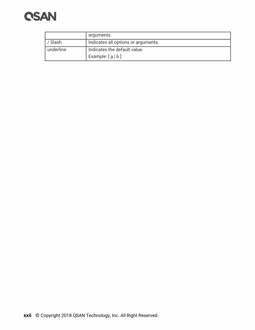
xxii © Copyright 2018 QSAN Technology, Inc. All Right Reserved.
arguments.
/ Slash Indicates all options or arguments.
underline Indicates the default value.
Example: [ a | b ]

SANOS Overview 1
1. SANOS Overview
SANOS (SAN Operating System) is QSAN’s proprietary SAN operating system and allows
you to manage, monitor, and analyze the configuration and performance of your XCubeSAN
series SAN storage system. This chapter provides an overview of the SANOS functionality
and includes a brief explanation of storage terminology for you to be more familiar with the
storage technologies used by the XCubeSAN system.
1.1. Introduction to SANOS
SANOS is equipped with a refreshingly simple to use web-based GUI and easily is
deployable into any infrastructure. Based on the Linux kernel, the 64-bit in-house developed
SANOS delivers comprehensive storage functionality and is suitable for primary or
secondary storage for SMB to entry-level enterprise businesses. The following sections will
introduce the SANOS system and storage pool architecture with enterprise-grade storage
features.
1.1.1. SANOS System Architecture
SANOS supports Dual Active (Active/Active) controller system architecture with high
availability. Figure 1-1 shows the SANOS system architecture with dual controller.
Figure 1-1 SANOS System Architecture
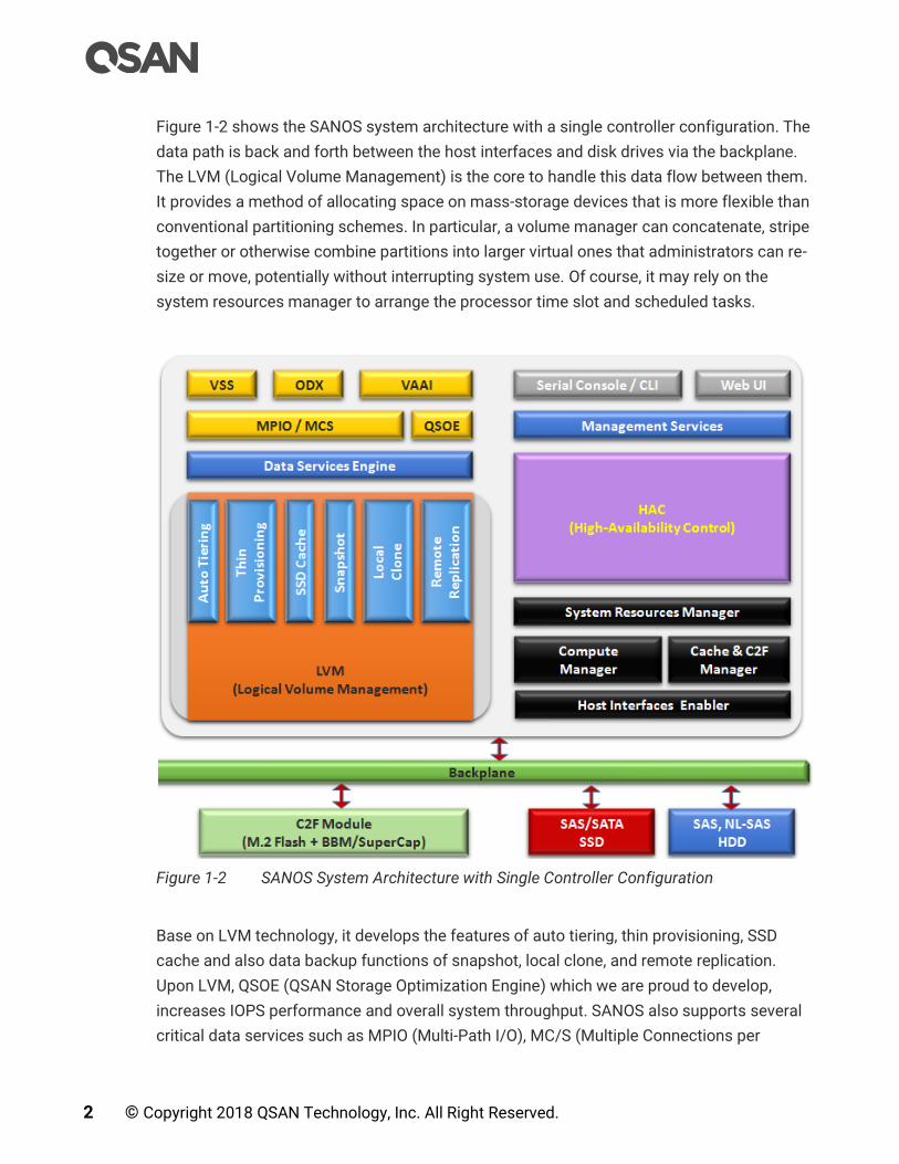
2 © Copyright 2018 QSAN Technology, Inc. All Right Reserved.
Figure 1-2 shows the SANOS system architecture with a single controller configuration. The
data path is back and forth between the host interfaces and disk drives via the backplane.
The LVM (Logical Volume Management) is the core to handle this data flow between them.
It provides a method of allocating space on mass-storage devices that is more flexible than
conventional partitioning schemes. In particular, a volume manager can concatenate, stripe
together or otherwise combine partitions into larger virtual ones that administrators can re-
size or move, potentially without interrupting system use. Of course, it may rely on the
system resources manager to arrange the processor time slot and scheduled tasks.
Figure 1-2 SANOS System Architecture with Single Controller Configuration
Base on LVM technology, it develops the features of auto tiering, thin provisioning, SSD
cache and also data backup functions of snapshot, local clone, and remote replication.
Upon LVM, QSOE (QSAN Storage Optimization Engine) which we are proud to develop,
increases IOPS performance and overall system throughput. SANOS also supports several
critical data services such as MPIO (Multi-Path I/O), MC/S (Multiple Connections per

SANOS Overview 3
Session), Microsoft VSS (Volume Shadow Copy Service), Microsoft ODX (Offloaded Data
Transfer), and VMware VAAI (VMware vSphere Storage APIs for Array Integration). In the
periphery, there are management service daemon to provide user interface operations, C2F
(Cache to Flash) mechanism includes BBM (Battery Backup Module) / SCM (SuperCap
Module) and M.2 flash module to protect cache data from power shortage. These key
enterprise storage features are all together in a single box.
Under the operation of dual controllers, HAC (High Availability Control) module has a
heartbeat mechanism to detect whether the other controller is alive. Cache mirror
synchronizes the memory data of both controllers including the status and storage
configuration. When one controller fails, the other controller can seamlessly take over all the
tasks of the failed controller thanks to this cache sync. In addition, zero system downtime
for the dual controller system takes place during firmware upgrading period.
1.1.2. SANOS Storage Pool Architecture
QSAN storage pool supports a variety of 3.5”/2.5” SAS/NL-SAS HDD and 2.5” SAS/SATA
SSD flash drives. Figure 1-3 shows the storage pool architecture. Several disk drives are
combined together to form a “disk group” with RAID protection. Then several disk groups
can be combined to form a storage pool. A volume (virtual disk) is then created out of the
storage pool and served to application servers over either iSCSI or Fibre Channel
connections.
Figure 1-3 SANOS Storage Pool Architecture

4 © Copyright 2018 QSAN Technology, Inc. All Right Reserved.
If the local disk drives are not enough, QSAN expansion enclosures including disk drives can
be added to increase storage capacity. There are host spares for standby if any disk drives
in pools fail. Base on snapshot technology, the data backup features such as local clone
and remote replications are also provided.
1.1.3. SANOS 4.0 Functionality List
SANOS 4.0 provides the following functionality for administrator management.
Figure 1-4 SANOS 4.0 Desktop Panel
System Management
Change system name, date and time.
Change admin’s password, user’s password, and configure login options.
Configure management IP address, DNS, and service ports.
Support boot management including auto shutdown, wake-on-LAN, and wake-on-SAS.
Support network UPS via SNMP.
Monitor cache to flash memory protection status. BBM (Battery Backup Module), SCM
(Super Capacitor Module), and flash module are optional add-ons.
Configure alert notifications through email, syslog server, or SNMP traps.
Obtain system information and download service package.
Update firmware of head unit or enclosure unit(s).

SANOS Overview 5
Change operation mode of single or dual controller.
Blink UID (Unique Identifier) LEDs for locating the storage arrays.
System reset to default, configuration backup, and volume restoration for maintenance
usage.
System reboot or shutdown.
Host Connectivity
Obtain host connectivity information.
Configure iSCSI connectivity with IP address, link aggregation, VLAN (Virtual LAN) ID
and jumbo frame.
Setup entity name and iSNS (Internet Storage Name Service).
Configure iSCSI target with CHAP (Challenge-Handshake Authentication Protocol) and
mutual CHAP authentication.
List and disconnect iSCSI sessions.
Configure fibre channel connectivity with link speed and topology.
Storage Management
Support RAID pool with RAID level 0, 1, 3, 5, 6, 0+1, 10, 30, 50, 60, and N-way mirror.
Support thick provisioning pool and online migrate RAID pool.
Support thin provisioning pool with space reclamation.
Support 3-tier auto tiering with scheduled relocation. (auto tiering function is optional)
Support SSD read cache or read-write cache to improve performance. (SSD cache
function is optional)
Support online storage pool capacity expansion and volume capacity extension.
Configure disk properties with disk write cache, disk read-ahead, command queuing, and
disk standby.
Configure volume properties with background I/O priority, volume write-back cache, and
video editing mode for enhanced performance.
Support access control for LUN mapping.
Support global, local, and dedicated hot spares for pool.
Support fast RAID rebuild.
Support disk drive health check and S.M.A.R.T attributes.
Support hard drive firmware batch update.
Support pool parity check and media scan for disk scrubbing.
Support pool activated and deactivated for disk roaming.
6 © Copyright 2018 QSAN Technology, Inc. All Right Reserved.
Data Backup
Support writable snapshot with manual or schedule tasks.
Support volume cloning for local replication.
Support remote replication with traffic shaping for dynamic bandwidth controller
Virtualization Integration
Seamless integrated with popular hypervisor including VMware vSphere, Microsoft
Hyper-V, and Citrix XenServer.
Monitoring
View event logs with different levels of event and download event logs.
Monitor enclosure status of head and enclosure units.
Monitor storage array performance.
1.2. Terminology
In this section, we introduce the terms that are used for the storage system throughout this
manual.
RAID
RAID is the abbreviation of Redundant Array of Independent Disks. There are different RAID
levels with different degrees of data protection, data availability, and performance to the
host environment.
Pools
A storage pool is a collection of disk drives. One pool consists of a set of volumes and owns
one RAID level attribute.
Volumes
Each pool can be divided into several volumes. The volumes from one pool have the same
RAID level, but may have different volume capacity.
Fast RAID Rebuild
When executing rebuild, the Fast RAID Rebuild feature skips any partition of the volume
where no write changes have occurred, it will focus only on the parts that have changed.
SANOS Overview 7
LUN
A LUN (Logical Unit Number) is a unique identifier for designating an individual or collection
of physical or virtual storage devices that execute I/O commands with a host computer, as
defined by the SCSI (Small Computer System Interface) standard.
iSCSI
iSCSI (Internet SCSI) is a protocol which encapsulates SCSI (Small Computer System
Interface) commands and data in TCP/IP packets for linking storage devices with servers
over common IP infrastructures.
Fibre Channel
Fibre channel is an extremely fast system interface. It was initially developed for use
primarily in the supercomputing field, but has become the standard connection type for
storage area networks (SAN) in enterprise storage.
SAS
Serial-attached SCSI offers advantages over older parallel technologies. The cables are
thinner, and the connectors are less bulky. Serial data transfer allows the use of longer
cables than parallel data connections.
Thick Provisioning
Thick provisioning is allocated upon creation the physical disk drive space and is equal to
the user capacity seen by the host server. It also called fat provisioning.
Thin Provisioning
Thin provisioning is allocated on-demand and can be less than the user capacity seen by the
host server. It involves using virtualization technology to give the appearance of having
more physical resources than are actually available.
Auto Tiering
Auto Tiering is the automated progression or demotion of data across different tiers (types)
of storage devices and media. The movement of data takes place in an automated way with
the help of software and is assigned to the related media according to performance and
capacity requirements. It also includes the ability to define rules and policies that dictate if
and when data can be moved between the tiers, and in many cases provides the ability to
pin data to tiers permanently or for specific periods of time.

8 © Copyright 2018 QSAN Technology, Inc. All Right Reserved.
SSD Cache
Smart Response Technology (also known as SSD cache) allows an SSD to function as
cache for a HDD volume. It is a secondary cache that improves performance by keeping
frequently accessed data on SSDs where they are read/write far more quickly than from the
HDD volume.
Snapshot
A volume snapshot is the state of a system at a particular point in time.
Local Clone
Local clone function has another physical data copy as the original volume.
Remote Replication
Remote replication function prevents primary site failure by replicating data to the remote
sites.
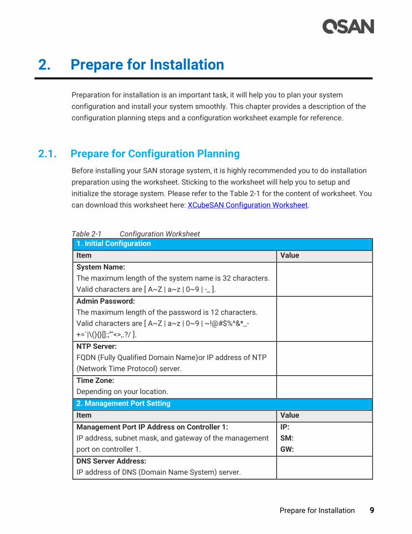
Prepare for Installation 9
2. Prepare for Installation
Preparation for installation is an important task, it will help you to plan your system
configuration and install your system smoothly. This chapter provides a description of the
configuration planning steps and a configuration worksheet example for reference.
2.1. Prepare for Configuration Planning
Before installing your SAN storage system, it is highly recommended you to do installation
preparation using the worksheet. Sticking to the worksheet will help you to setup and
initialize the storage system. Please refer to the Table 2-1 for the content of worksheet. You
can download this worksheet here: XCubeSAN Configuration Worksheet.
Table 2-1 Configuration Worksheet
1. Initial Configuration
Item Value
System Name:
The maximum length of the system name is 32 characters.
Valid characters are [ A~Z | a~z | 0~9 | -_ ].
Admin Password:
The maximum length of the password is 12 characters.
Valid characters are [ A~Z | a~z | 0~9 | ~!@#$%^&*_-
+=`|\(){}[]:;”’<>,.?/ ].
NTP Server:
FQDN (Fully Qualified Domain Name)or IP address of NTP
(Network Time Protocol) server.
Time Zone:
Depending on your location.
2. Management Port Setting
Item Value
Management Port IP Address on Controller 1:
IP address, subnet mask, and gateway of the management
port on controller 1.
IP:
SM:
GW:
DNS Server Address:
IP address of DNS (Domain Name System) server.
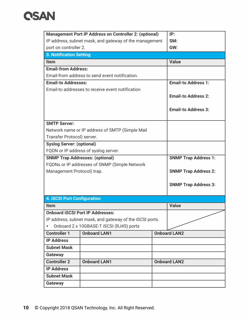
10 © Copyright 2018 QSAN Technology, Inc. All Right Reserved.
Management Port IP Address on Controller 2: (optional)
IP address, subnet mask, and gateway of the management
port on controller 2.
IP:
SM:
GW:
3. Notification Setting
Item Value
Email-from Address:
Email-from address to send event notification.
Email-to Addresses:
Email-to addresses to receive event notification
Email-to Address 1:
Email-to Address 2:
Email-to Address 3:
SMTP Server:
Network name or IP address of SMTP (Simple Mail
Transfer Protocol) server.
Syslog Server: (optional)
FQDN or IP address of syslog server.
SNMP Trap Addresses: (optional)
FQDNs or IP addresses of SNMP (Simple Network
Management Protocol) trap.
SNMP Trap Address 1:
SNMP Trap Address 2:
SNMP Trap Address 3:
4. iSCSI Port Configuration
Item Value
Onboard iSCSI Port IP Addresses:
IP address, subnet mask, and gateway of the iSCSI ports.
Onboard 2 x 10GBASE-T iSCSI (RJ45) ports
Controller 1 Onboard LAN1 Onboard LAN2
IP Address
Subnet Mask
Gateway
Controller 2 Onboard LAN1 Onboard LAN2
IP Address
Subnet Mask
Gateway
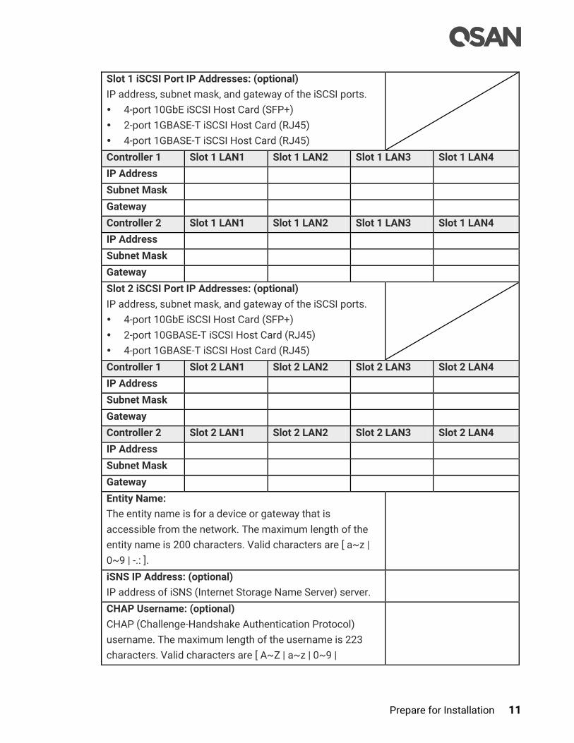
Prepare for Installation 11
Slot 1 iSCSI Port IP Addresses: (optional)
IP address, subnet mask, and gateway of the iSCSI ports.
4-port 10GbE iSCSI Host Card (SFP+)
2-port 1GBASE-T iSCSI Host Card (RJ45)
4-port 1GBASE-T iSCSI Host Card (RJ45)
Controller 1 Slot 1 LAN1 Slot 1 LAN2 Slot 1 LAN3 Slot 1 LAN4
IP Address
Subnet Mask
Gateway
Controller 2 Slot 1 LAN1 Slot 1 LAN2 Slot 1 LAN3 Slot 1 LAN4
IP Address
Subnet Mask
Gateway
Slot 2 iSCSI Port IP Addresses: (optional)
IP address, subnet mask, and gateway of the iSCSI ports.
4-port 10GbE iSCSI Host Card (SFP+)
2-port 10GBASE-T iSCSI Host Card (RJ45)
4-port 1GBASE-T iSCSI Host Card (RJ45)
Controller 1 Slot 2 LAN1 Slot 2 LAN2 Slot 2 LAN3 Slot 2 LAN4
IP Address
Subnet Mask
Gateway
Controller 2 Slot 2 LAN1 Slot 2 LAN2 Slot 2 LAN3 Slot 2 LAN4
IP Address
Subnet Mask
Gateway
Entity Name:
The entity name is for a device or gateway that is
accessible from the network. The maximum length of the
entity name is 200 characters. Valid characters are [ a~z |
0~9 | -.: ].
iSNS IP Address: (optional)
IP address of iSNS (Internet Storage Name Server) server.
CHAP Username: (optional)
CHAP (Challenge-Handshake Authentication Protocol)
username. The maximum length of the username is 223
characters. Valid characters are [ A~Z | a~z | 0~9 |

12 © Copyright 2018 QSAN Technology, Inc. All Right Reserved.
~!@#%^&*_-+=|(){}[]:;<>.?/ ].
CHAP Password: (optional)
CHAP password. The length of the password is between12
to 16 characters. Valid characters are [ A~Z | a~z | 0~9 |
~!@#$%^&*_-+=`|\(){}[]:;”’<>,.?/ ].
Mutual CHAP Username: (optional)
Mutual CHAP username. The maximum length of the
username is 223 characters. Valid characters are [ A~Z |
a~z | 0~9 | ~!@#%^&*_-+=|(){}[]:;<>.?/ ].
Mutual CHAP Password: (optional)
Mutual CHAP password. The length of the password is
between12 to 16 characters. Valid characters are [ A~Z |
a~z | 0~9 | ~!@#$%^&*_-+=`|\(){}[]:;”’<>,.?/ ].
5. Fibre Channel Port Configuration
Item Value
Slot 1 Fibre Channel: (optional)
Link speed and topology of the fibre channel ports.
Topology support: FC-AL, point-to-point (16Gb Fibre
Channel only supports Point-to-Point topology)
4-port 16Gb Fibre Channel Host Card (SFP+)
2-port 16Gb Fibre Channel Host Card (SFP+)
Controller 1 Slot 1 FC1 Slot 1 FC2 Slot 1 FC3 Slot 1 FC4
Link Speed
Topology
Controller 2 Slot 1 FC1 Slot 1 FC2 Slot 1 FC3 Slot 1 FC4
Link Speed
Topology
6. Pool Configuration
Item Value
Pool Type:
Thick Provisioning, Thin Provisioning, or Auto Tiering (Thin
Provisioning Enabled).
Pool Name:
The maximum length of the pool name is 16 characters.
Valid characters are [ A~Z | a~z | 0~9 | -_<> ].
Disks:
Disk type, disk quantity, and the capacity.
SSD:
SAS:

Prepare for Installation 13
NL-SAS:
RAID Level:
RAID level 0, 1, 3, 5, 6, 0+1, 10, 30, 50, 60, and N-way mirror
RAID EE level 5EE, 6EE, 50EE, and 60EE
Raw Capacity:
Sum of disk capacity.
Estimate Capacity:
Estimate capacity according to the RAID level.
7. Volume Configuration
Item Value
Volume Name:
The maximum length of the volume name is 32 characters.
Valid characters are [ A~Z | a~z | 0~9 | -_<> ].
Capacity:
Required capacity of the volume.
Volume Type:
RAID Volume or Backup Volume
8. LUN Mapping Configuration
Item Value
Protocol:
iSCSI or FCP.
Volume Name:
Select one of created volumes.
Allowed Hosts:
iSCSI IQN or Fibre Channel WWNN for access control.
Wildcard (*) for access by all hosts.
Target:
iSCSI Target or Fibre Channel Target
LUN:
Support LUN (Logical Unit Number) from 0 to 255.
Permission:
Read-only or Read-write.
9. SSD Cache Configuration
Item Value
SSD Cache Pool Name:
The maximum length of the pool name is 16 characters.
Valid characters are [ A~Z | a~z | 0~9 | -_<> ].
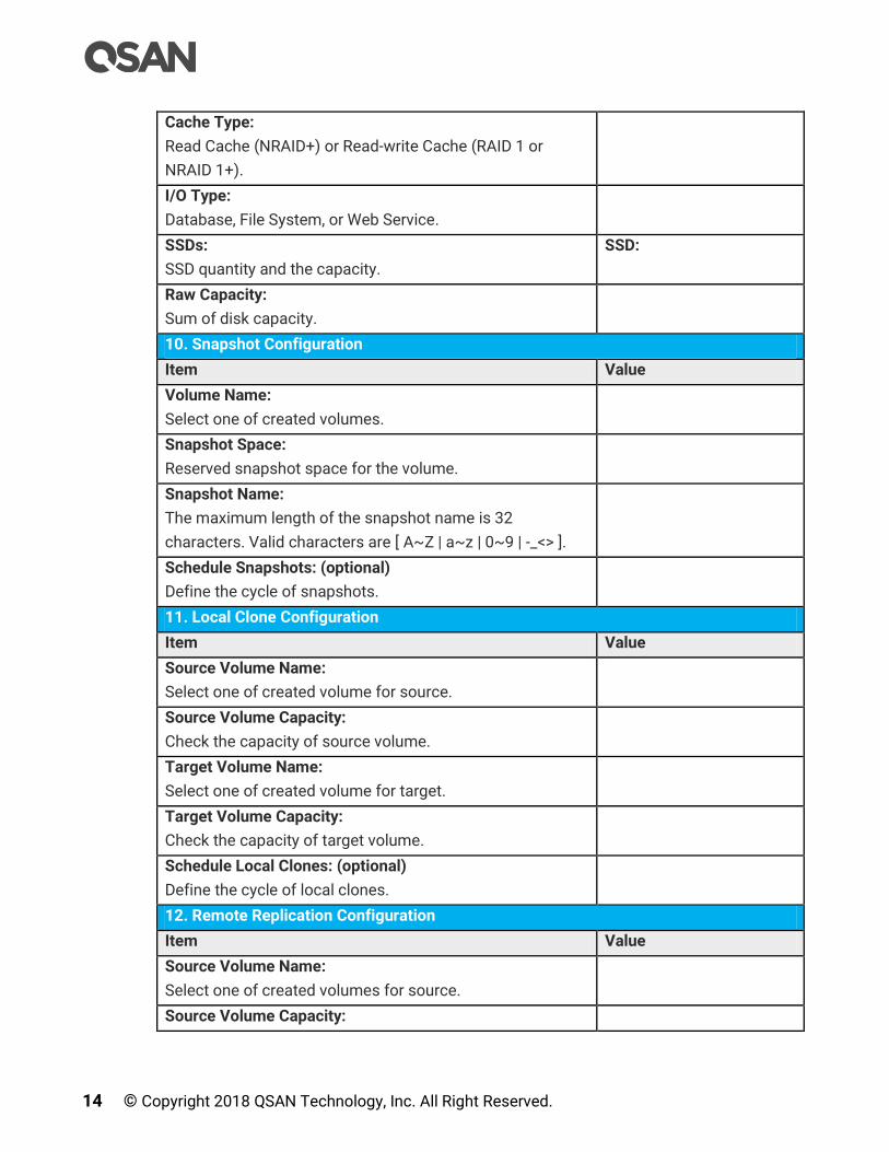
14 © Copyright 2018 QSAN Technology, Inc. All Right Reserved.
Cache Type:
Read Cache (NRAID+) or Read-write Cache (RAID 1 or
NRAID 1+).
I/O Type:
Database, File System, or Web Service.
SSDs:
SSD quantity and the capacity.
SSD:
Raw Capacity:
Sum of disk capacity.
10. Snapshot Configuration
Item Value
Volume Name:
Select one of created volumes.
Snapshot Space:
Reserved snapshot space for the volume.
Snapshot Name:
The maximum length of the snapshot name is 32
characters. Valid characters are [ A~Z | a~z | 0~9 | -_<> ].
Schedule Snapshots: (optional)
Define the cycle of snapshots.
11. Local Clone Configuration
Item Value
Source Volume Name:
Select one of created volume for source.
Source Volume Capacity:
Check the capacity of source volume.
Target Volume Name:
Select one of created volume for target.
Target Volume Capacity:
Check the capacity of target volume.
Schedule Local Clones: (optional)
Define the cycle of local clones.
12. Remote Replication Configuration
Item Value
Source Volume Name:
Select one of created volumes for source.
Source Volume Capacity:
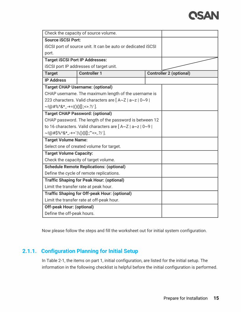
Prepare for Installation 15
Check the capacity of source volume.
Source iSCSI Port:
iSCSI port of source unit. It can be auto or dedicated iSCSI
port.
Target iSCSI Port IP Addresses:
iSCSI port IP addresses of target unit.
Target Controller 1 Controller 2 (optional)
IP Address
Target CHAP Username: (optional)
CHAP username. The maximum length of the username is
223 characters. Valid characters are [ A~Z | a~z | 0~9 |
~!@#%^&*_-+=|(){}[]:;<>.?/ ].
Target CHAP Password: (optional)
CHAP password. The length of the password is between 12
to 16 characters. Valid characters are [ A~Z | a~z | 0~9 |
~!@#$%^&*_-+=`|\(){}[]:;”’<>,.?/ ].
Target Volume Name:
Select one of created volume for target.
Target Volume Capacity:
Check the capacity of target volume.
Schedule Remote Replications: (optional)
Define the cycle of remote replications.
Traffic Shaping for Peak Hour: (optional)
Limit the transfer rate at peak hour.
Traffic Shaping for Off-peak Hour: (optional)
Limit the transfer rate at off-peak hour.
Off-peak Hour: (optional)
Define the off-peak hours.
Now please follow the steps and fill the worksheet out for initial system configuration.
2.1.1. Configuration Planning for Initial Setup
In Table 2-1, the items on part 1, initial configuration, are listed for the initial setup. The
information in the following checklist is helpful before the initial configuration is performed.

16 © Copyright 2018 QSAN Technology, Inc. All Right Reserved.
System name allows maximum 32 characters. Valid characters are [ A~Z | a~z | 0~9 | -
_<> ].
Administrator password allows maximum 12 characters. Valid characters are [ A~Z |
a~z | 0~9 | ~!@#$%^&*_-+=`|\(){}[]:;”’<>,.?/ ].
The date and time can be manually entered, but to keep the clock synchronized,
recommend using a NTP (Network Time Protocol) service.
Enter the time zone based on your geographical location.
2.1.2. Management IP Configuration Planning
With your network administrator, determine the IP addresses and network parameters you
plan to use with the storage system, and record the information on part 2, management port
setting in Table 2-1. You can manage the storage system through a dedicated management
port at least on controller 1. This port must share a same subnet with the host you use to
initialize the system. After initialization, any host on the same network and with a supported
browser can manage the system through the management port.
It is recommended using a static IP address for the management port. Please prepare a
list of the static IP addresses, the subnet mask, and the default gateway.
DNS (Domain Name Service) server address provides a means to translate FQDN (Fully
Qualified Domain Name) to IP address. Some notification services need DNS setting.
For dual controller configurations, the management port IP address on controller 2 is
optional. If enabling the dual management ports setting, both management ports of
controller 1 and 2 have their own IP addresses, and both are active. Otherwise, only the
management port of master controller is active, the other one is standby. The
management port fails over to the slave controller when the master controller goes
offline even planned or unplanned.
2.1.3. Notification Configuration Planning
On part 3, notification setting in Table 2-1, prepare to configure the notification. It’s helpful
for monitoring the system health.
SMTP server and email address to direct notification alerts the IT administrator and any
alternate or back-up personnel.
Syslog server address to log monitored events.
SNMP (Simple Network Management Protocol) trap to send system event logs to SNMP
trap agent.

Prepare for Installation 17
2.1.4. iSCSI Configuration Planning
Although SAN is a private network environment, IP addresses of iSCSI data ports should be
planned, too. Optionally, CHAP security information, including CHAP username and
password should be prepared.
For an iSCSI dual-controller system, recommend to install an iSNS server on the same
storage area network. For better usage of failover, the host must logon the target twice
(both controller 1 and controller 2), and then the MPIO should setup automatically. More
advanced, all the connections among hosts (with clustering), switches, and the dual-
controller are recommended as redundant as shown below.
Figure 2-1 Dual-controller Topology
If you are using onboard iSCSI LAN ports, please fill in part 4, onboard iSCSI port IP
addresses of iSCSI port configuration. Optionally, if you have iSCSI host card at slot 1 and
slot 2, please fill in iSCSI port IP address.
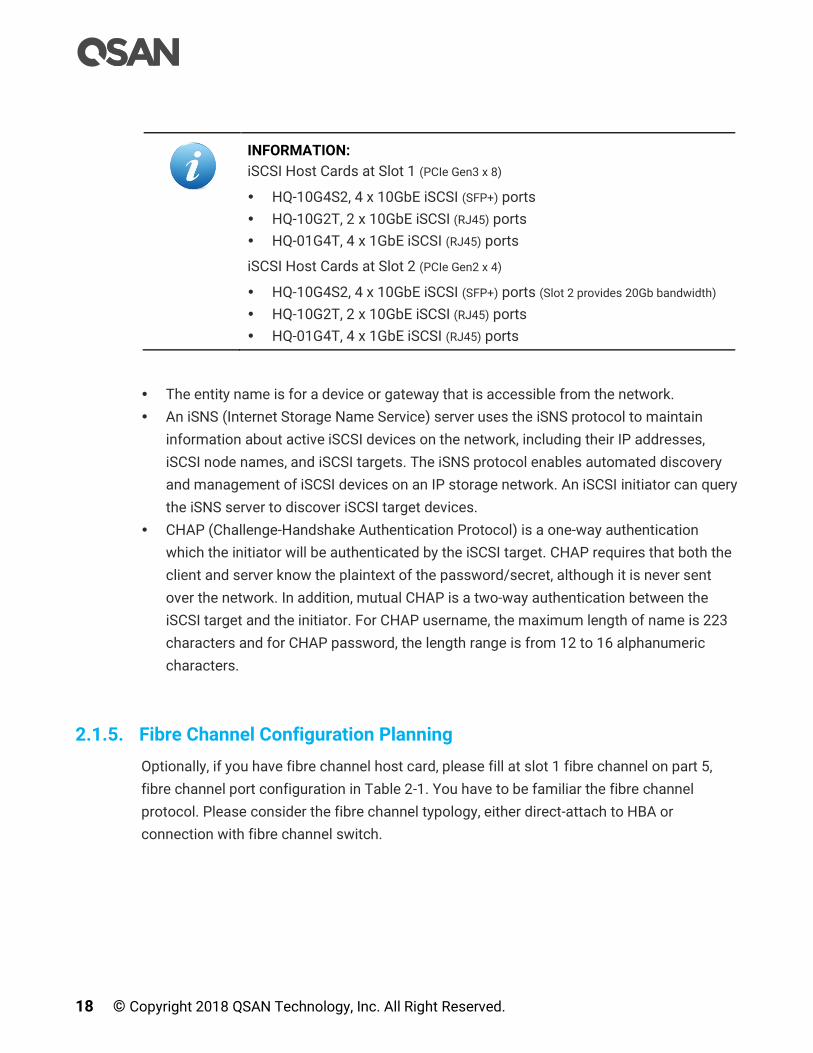
18 © Copyright 2018 QSAN Technology, Inc. All Right Reserved.
INFORMATION:
iSCSI Host Cards at Slot 1 (PCIe Gen3 x 8)
HQ-10G4S2, 4 x 10GbE iSCSI (SFP+) ports
HQ-10G2T, 2 x 10GbE iSCSI (RJ45) ports
HQ-01G4T, 4 x 1GbE iSCSI (RJ45) ports
iSCSI Host Cards at Slot 2 (PCIe Gen2 x 4)
HQ-10G4S2, 4 x 10GbE iSCSI (SFP+) ports (Slot 2 provides 20Gb bandwidth)
HQ-10G2T, 2 x 10GbE iSCSI (RJ45) ports
HQ-01G4T, 4 x 1GbE iSCSI (RJ45) ports
The entity name is for a device or gateway that is accessible from the network.
An iSNS (Internet Storage Name Service) server uses the iSNS protocol to maintain
information about active iSCSI devices on the network, including their IP addresses,
iSCSI node names, and iSCSI targets. The iSNS protocol enables automated discovery
and management of iSCSI devices on an IP storage network. An iSCSI initiator can query
the iSNS server to discover iSCSI target devices.
CHAP (Challenge-Handshake Authentication Protocol) is a one-way authentication
which the initiator will be authenticated by the iSCSI target. CHAP requires that both the
client and server know the plaintext of the password/secret, although it is never sent
over the network. In addition, mutual CHAP is a two-way authentication between the
iSCSI target and the initiator. For CHAP username, the maximum length of name is 223
characters and for CHAP password, the length range is from 12 to 16 alphanumeric
characters.
2.1.5. Fibre Channel Configuration Planning
Optionally, if you have fibre channel host card, please fill at slot 1 fibre channel on part 5,
fibre channel port configuration in Table 2-1. You have to be familiar the fibre channel
protocol. Please consider the fibre channel typology, either direct-attach to HBA or
connection with fibre channel switch.
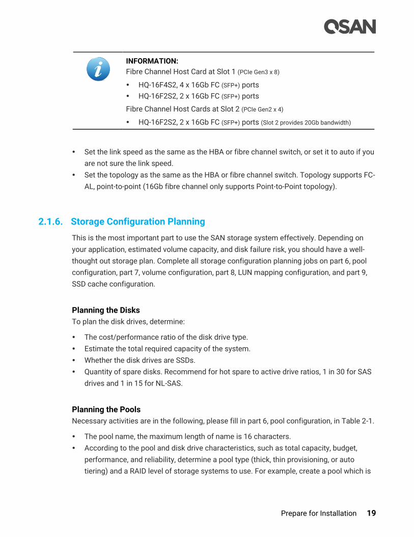
Prepare for Installation 19
INFORMATION:
Fibre Channel Host Card at Slot 1 (PCIe Gen3 x 8)
HQ-16F4S2, 4 x 16Gb FC (SFP+) ports
HQ-16F2S2, 2 x 16Gb FC (SFP+) ports
Fibre Channel Host Cards at Slot 2 (PCIe Gen2 x 4)
HQ-16F2S2, 2 x 16Gb FC (SFP+) ports (Slot 2 provides 20Gb bandwidth)
Set the link speed as the same as the HBA or fibre channel switch, or set it to auto if you
are not sure the link speed.
Set the topology as the same as the HBA or fibre channel switch. Topology supports FC-
AL, point-to-point (16Gb fibre channel only supports Point-to-Point topology).
2.1.6. Storage Configuration Planning
This is the most important part to use the SAN storage system effectively. Depending on
your application, estimated volume capacity, and disk failure risk, you should have a well-
thought out storage plan. Complete all storage configuration planning jobs on part 6, pool
configuration, part 7, volume configuration, part 8, LUN mapping configuration, and part 9,
SSD cache configuration.
Planning the Disks
To plan the disk drives, determine:
The cost/performance ratio of the disk drive type.
Estimate the total required capacity of the system.
Whether the disk drives are SSDs.
Quantity of spare disks. Recommend for hot spare to active drive ratios, 1 in 30 for SAS
drives and 1 in 15 for NL-SAS.
Planning the Pools
Necessary activities are in the following, please fill in part 6, pool configuration, in Table 2-1.
The pool name, the maximum length of name is 16 characters.
According to the pool and disk drive characteristics, such as total capacity, budget,
performance, and reliability, determine a pool type (thick, thin provisioning, or auto
tiering) and a RAID level of storage systems to use. For example, create a pool which is
20 © Copyright 2018 QSAN Technology, Inc. All Right Reserved.
grouped by RAID 10 for performance and RAID 5 in another storage pool to achieve
desired results.
Plan to extend the capacity of the storage pool in the future.
Planning the Volumes
A volume is a member of the pool. Determine the following items and fill in part 7, volume
configuration, in Table 2-1.
The volume name, the maximum length of name is 32 characters.
The volume capacity.
Plan the volume capacity for local clone or remote replication. Set it as RAID volume for
normal RAID volume usage, or set it as backup volume for the backup target of local
clone or remote replication.
Planning the LUNs
LUN is a unique identifier which volume maps it to differentiate among separate devices. At
the same time, there are some access controls by allowed hosts, target, LUN (logic unit
number), and read/write permission. Please fill in part 8, LUN mapping configuration, in
Table 2-1.
Prepare an allowed host list for access control. They are (iSCSI Qualified Name) or Fibre
Channel WWNN (World Wide Node Name). Set it as wildcard (*) for access by all hosts.
Select an iSCSI target for iSCSI network portal. Or a FC target.
Support LUN from 0 to 255.
Usually, set the volume as read-write permission. For read only purpose, set it as read-
only.
Planning the SSD Cache
Optionally, preparing for some SSDs will enhance the system performance. Please fill in part
9, SSD cache configuration, in Table 2-1.
For SSD cache planning, the capacity of read cache is the sum of SSDs. But the capacity
of read-write cache is half of all SSDs because it needs RAID protection for write buffer.
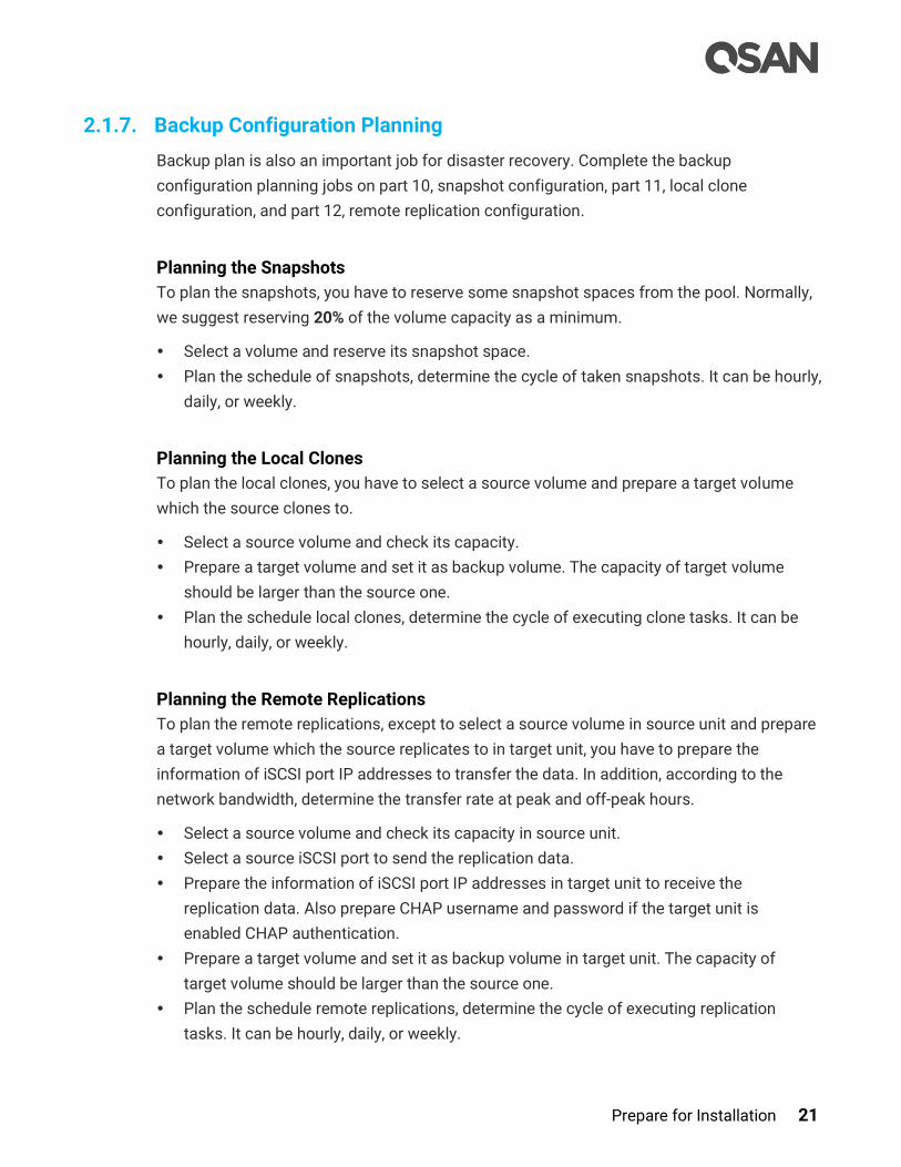
Prepare for Installation 21
2.1.7. Backup Configuration Planning
Backup plan is also an important job for disaster recovery. Complete the backup
configuration planning jobs on part 10, snapshot configuration, part 11, local clone
configuration, and part 12, remote replication configuration.
Planning the Snapshots
To plan the snapshots, you have to reserve some snapshot spaces from the pool. Normally,
we suggest reserving 20% of the volume capacity as a minimum.
Select a volume and reserve its snapshot space.
Plan the schedule of snapshots, determine the cycle of taken snapshots. It can be hourly,
daily, or weekly.
Planning the Local Clones
To plan the local clones, you have to select a source volume and prepare a target volume
which the source clones to.
Select a source volume and check its capacity.
Prepare a target volume and set it as backup volume. The capacity of target volume
should be larger than the source one.
Plan the schedule local clones, determine the cycle of executing clone tasks. It can be
hourly, daily, or weekly.
Planning the Remote Replications
To plan the remote replications, except to select a source volume in source unit and prepare
a target volume which the source replicates to in target unit, you have to prepare the
information of iSCSI port IP addresses to transfer the data. In addition, according to the
network bandwidth, determine the transfer rate at peak and off-peak hours.
Select a source volume and check its capacity in source unit.
Select a source iSCSI port to send the replication data.
Prepare the information of iSCSI port IP addresses in target unit to receive the
replication data. Also prepare CHAP username and password if the target unit is
enabled CHAP authentication.
Prepare a target volume and set it as backup volume in target unit. The capacity of
target volume should be larger than the source one.
Plan the schedule remote replications, determine the cycle of executing replication
tasks. It can be hourly, daily, or weekly.
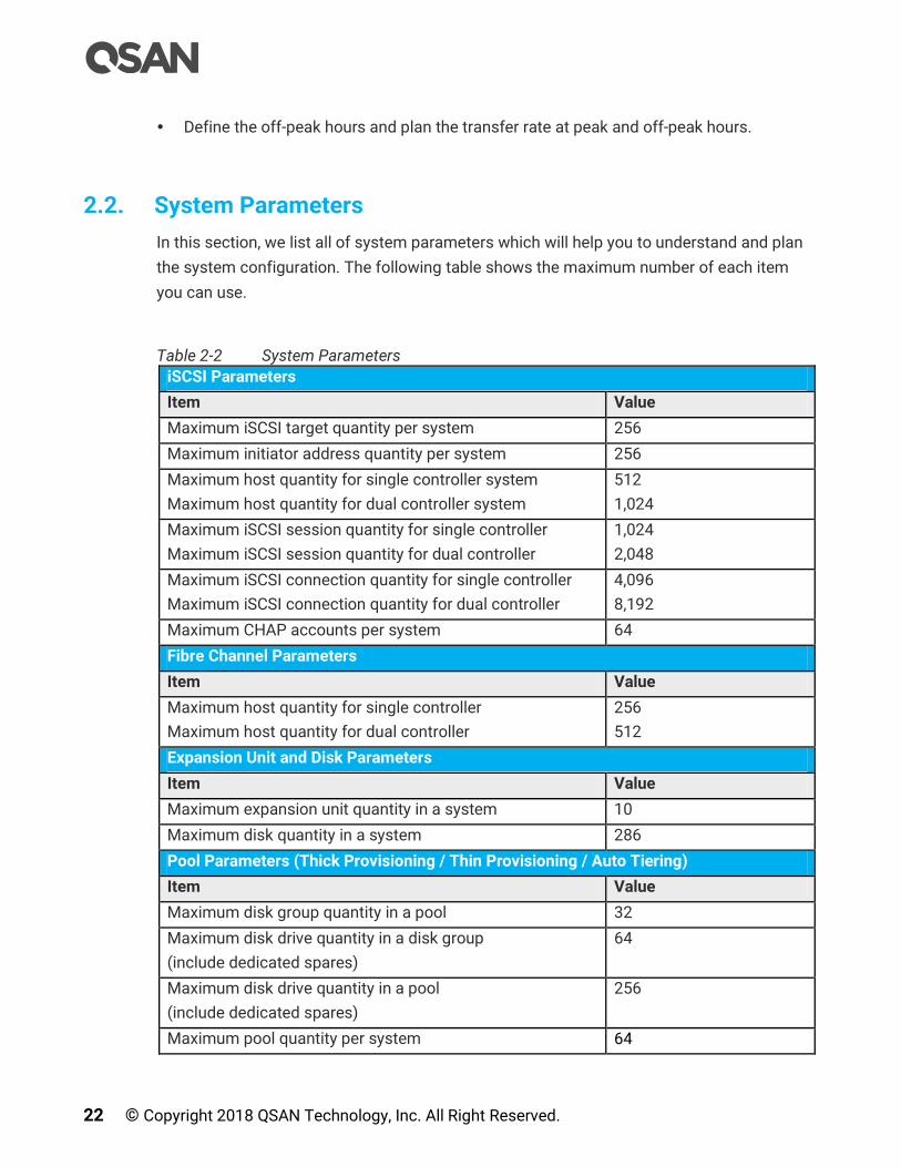
22 © Copyright 2018 QSAN Technology, Inc. All Right Reserved.
Define the off-peak hours and plan the transfer rate at peak and off-peak hours.
2.2. System Parameters
In this section, we list all of system parameters which will help you to understand and plan
the system configuration. The following table shows the maximum number of each item
you can use.
Table 2-2 System Parameters
iSCSI Parameters
Item Value
Maximum iSCSI target quantity per system 256
Maximum initiator address quantity per system 256
Maximum host quantity for single controller system
Maximum host quantity for dual controller system
512
1,024
Maximum iSCSI session quantity for single controller
Maximum iSCSI session quantity for dual controller
1,024
2,048
Maximum iSCSI connection quantity for single controller
Maximum iSCSI connection quantity for dual controller
4,096
8,192
Maximum CHAP accounts per system 64
Fibre Channel Parameters
Item Value
Maximum host quantity for single controller
Maximum host quantity for dual controller
256
512
Expansion Unit and Disk Parameters
Item Value
Maximum expansion unit quantity in a system 10
Maximum disk quantity in a system 286
Pool Parameters (Thick Provisioning / Thin Provisioning / Auto Tiering)
Item Value
Maximum disk group quantity in a pool 32
Maximum disk drive quantity in a disk group
(include dedicated spares)
64
Maximum disk drive quantity in a pool
(include dedicated spares)
256
Maximum pool quantity per system 64
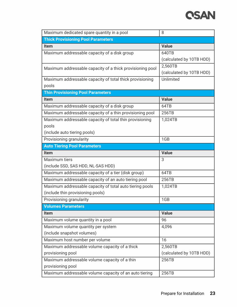
Prepare for Installation 23
Maximum dedicated spare quantity in a pool 8
Thick Provisioning Pool Parameters
Item Value
Maximum addressable capacity of a disk group 640TB
(calculated by 10TB HDD)
Maximum addressable capacity of a thick provisioning pool 2,560TB
(calculated by 10TB HDD)
Maximum addressable capacity of total thick provisioning
pools
Unlimited
Thin Provisioning Pool Parameters
Item Value
Maximum addressable capacity of a disk group 64TB
Maximum addressable capacity of a thin provisioning pool 256TB
Maximum addressable capacity of total thin provisioning
pools
(include auto tiering pools)
1,024TB
Provisioning granularity 1GB
Auto Tiering Pool Parameters
Item Value
Maximum tiers
(include SSD, SAS HDD, NL-SAS HDD)
3
Maximum addressable capacity of a tier (disk group) 64TB
Maximum addressable capacity of an auto tiering pool 256TB
Maximum addressable capacity of total auto tiering pools
(include thin provisioning pools)
1,024TB
Provisioning granularity 1GB
Volumes Parameters
Item Value
Maximum volume quantity in a pool 96
Maximum volume quantity per system
(include snapshot volumes)
4,096
Maximum host number per volume 16
Maximum addressable volume capacity of a thick
provisioning pool
2,560TB
(calculated by 10TB HDD)
Maximum addressable volume capacity of a thin
provisioning pool
256TB
Maximum addressable volume capacity of an auto tiering 256TB
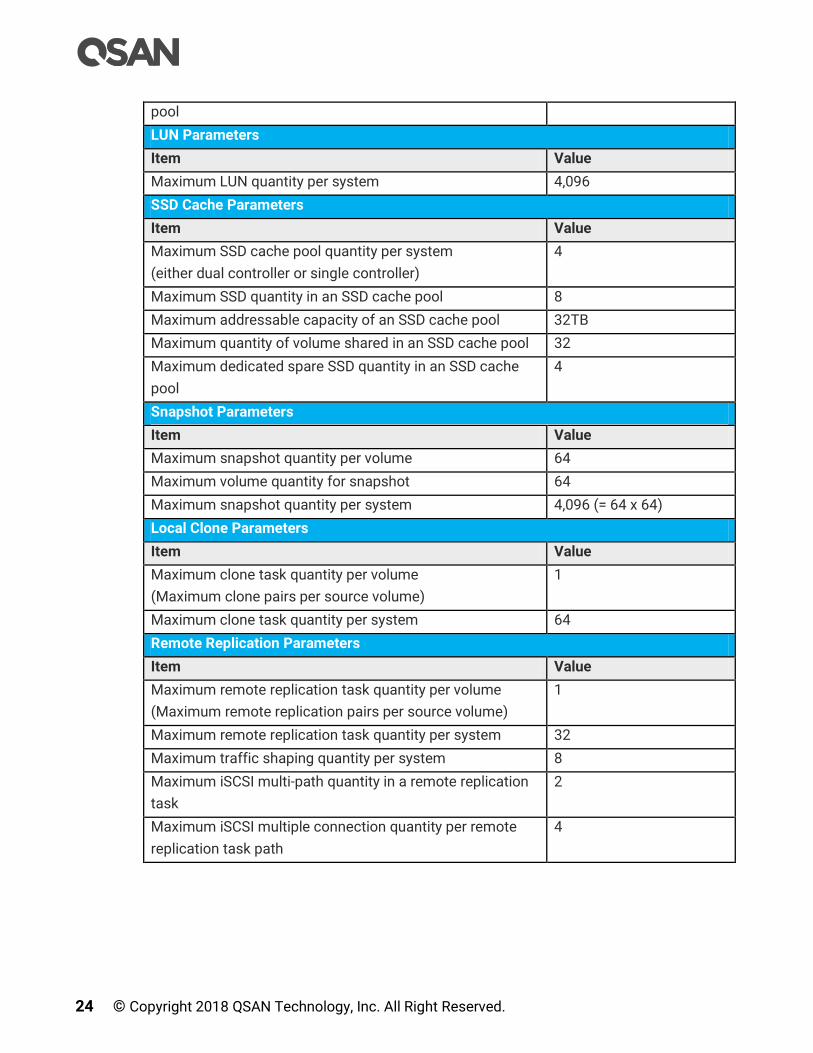
24 © Copyright 2018 QSAN Technology, Inc. All Right Reserved.
pool
LUN Parameters
Item Value
Maximum LUN quantity per system 4,096
SSD Cache Parameters
Item Value
Maximum SSD cache pool quantity per system
(either dual controller or single controller)
4
Maximum SSD quantity in an SSD cache pool 8
Maximum addressable capacity of an SSD cache pool 32TB
Maximum quantity of volume shared in an SSD cache pool 32
Maximum dedicated spare SSD quantity in an SSD cache
pool
4
Snapshot Parameters
Item Value
Maximum snapshot quantity per volume 64
Maximum volume quantity for snapshot 64
Maximum snapshot quantity per system 4,096 (= 64 x 64)
Local Clone Parameters
Item Value
Maximum clone task quantity per volume
(Maximum clone pairs per source volume)
1
Maximum clone task quantity per system 64
Remote Replication Parameters
Item Value
Maximum remote replication task quantity per volume
(Maximum remote replication pairs per source volume)
1
Maximum remote replication task quantity per system 32
Maximum traffic shaping quantity per system 8
Maximum iSCSI multi-path quantity in a remote replication
task
2
Maximum iSCSI multiple connection quantity per remote
replication task path
4

Prepare for Installation 25
2.3. Configuration Example
The following is an example of finished configuration worksheet just for reference.
Table 2-3 Configuration Worksheet Example
1. Initial Configuration
Item Value
System Name:
The maximum length of the system name is 32 characters.
Valid characters are [ A~Z | a~z | 0~9 | -_ ].
XCubeSAN
Admin Password:
The maximum length of the password is 12 characters.
Valid characters are [ A~Z | a~z | 0~9 | ~!@#$%^&*_-
+=`|\(){}[]:;”’<>,.?/ ].
1234
NTP Server:
FQDN (Fully Qualified Domain Name)or IP address of NTP
(Network Time Protocol) server.
pool.ntp.org
Time Zone:
Depending on your location.
(GM +08:00) Taipei
2. Management Port Setting
Item Value
Management Port IP Address on Controller 1:
IP address, subnet mask, and gateway of the management
port on controller 1.
IP: 192.168.1.234
SM: 255.255.255.0
GW: 192.168.1.254
DNS Server Address:
IP address of DNS (Domain Name System) server.
8.8.8.8
Management Port IP Address on Controller 2: (optional)
IP address, subnet mask, and gateway of the management
port on controller 2.
IP: 192.168.1.235
SM: 255.255.255.0
GW: 192.168.1.254
3. Notification Setting
Item Value
Email-from Address:
Email-from address to send event notification.
Email-to Addresses:
Email-to addresses to receive event notification
Email-to Address 1:
Email-to Address 2:

26 © Copyright 2018 QSAN Technology, Inc. All Right Reserved.
Email-to Address 3:
SMTP Server:
Network name or IP address of SMTP (Simple Mail
Transfer Protocol) server.
smtp.company.com
Syslog Server: (optional)
FQDN or IP address of syslog server.
syslog.company.com
SNMP Trap Addresses: (optional)
FQDNs or IP addresses of SNMP (Simple Network
Management Protocol) trap.
SNMP Trap Address 1:
snmp1.company.com
SNMP Trap Address 2:
snmp2.company.com
SNMP Trap Address 3:
snmp3.company.com
4. iSCSI Port Configuration
Item Value
Onboard iSCSI Port IP Addresses:
IP address, subnet mask, and gateway of the iSCSI ports.
Onboard 2 x 10GBASE-T iSCSI (RJ45) ports
Controller 1 Onboard LAN1 Onboard LAN2
IP Address 10.10.1.1 10.10.2.1
Subnet Mask 255.255.255.0 255.255.255.0
Gateway 10.10.1.254 10.10.2.254
Controller 2 Onboard LAN1 Onboard LAN2
IP Address 10.10.3.1 10.10.4.1
Subnet Mask 255.255.255.0 255.255.255.0
Gateway 10.10.3.254 10.10.4.254
Slot 1 iSCSI Port IP Addresses: (optional)
IP address, subnet mask, and gateway of the iSCSI ports.
4-port 10GbE iSCSI Host Card (SFP+)
2-port 1GBASE-T iSCSI Host Card (RJ45)
4-port 1GBASE-T iSCSI Host Card (RJ45)
Controller 1 Slot 1 LAN1 Slot 1 LAN2 Slot 1 LAN3 Slot 1 LAN4
IP Address 10.10.11.1
Subnet Mask 255.255.255.0
Gateway 10.10.11.254
Controller 2 Slot 1 LAN1 Slot 1 LAN2 Slot 1 LAN3 Slot 1 LAN4
IP Address 10.10.21.1

Prepare for Installation 27
Subnet Mask 255.255.255.0
Gateway 10.10.21.254
Slot 2 iSCSI Port IP Addresses: (optional)
IP address, subnet mask, and gateway of the iSCSI ports.
4-port 10GbE iSCSI Host Card (SFP+)
2-port 1GBASE-T iSCSI Host Card (RJ45)
4-port 1GBASE-T iSCSI Host Card (RJ45)
Controller 1 Slot 2 LAN1 Slot 2 LAN2 Slot 2 LAN3 Slot 2 LAN4
IP Address 10.10.31.1
Subnet Mask 255.255.255.0
Gateway 10.10.31.254
Controller 2 Slot 2 LAN1 Slot 2 LAN2 Slot 2 LAN3 Slot 2 LAN4
IP Address 10.10.41.1
Subnet Mask 255.255.255.0
Gateway 10.10.41.254
Entity Name:
The entity name is for a device or gateway that is
accessible from the network. The maximum length of the
entity name is 200 characters. Valid characters are [ a~z |
0~9 | -.: ].
Iqn.2004-08.com.qsan
iSNS IP Address: (optional)
IP address of iSNS (Internet Storage Name Server) server.
10.1.1.1
CHAP Username: (optional)
CHAP (Challenge-Handshake Authentication Protocol)
username. The maximum length of the username is 223
characters. Valid characters are [ A~Z | a~z | 0~9 |
~!@#%^&*_-+=|(){}[]:;<>.?/ ].
chap1
CHAP Password: (optional)
CHAP password. The length of the password is between12
to 16 characters. Valid characters are [ A~Z | a~z | 0~9 |
~!@#$%^&*_-+=`|\(){}[]:;”’<>,.?/ ].
123456789012
Mutual CHAP Username: (optional)
CHAP (Challenge-Handshake Authentication Protocol)
username. The maximum length of the username is 223
characters. Valid characters are [ A~Z | a~z | 0~9 |
~!@#%^&*_-+=|(){}[]:;<>.?/ ].
mutualchap1
Mutual CHAP Password: (optional) 123456789012

28 © Copyright 2018 QSAN Technology, Inc. All Right Reserved.
CHAP password. The length of the password is between12
to 16 characters. Valid characters are [ A~Z | a~z | 0~9 |
~!@#$%^&*_-+=`|\(){}[]:;”’<>,.?/ ].
5. Fibre Channel Port Configuration
Item Value
Slot 1 Fibre Channel: (optional)
Link speed and topology of the fibre channel ports.
Topology support: FC-AL, point-to-point (16Gb Fibre
Channel only supports Point-to-Point topology)
4-port 16Gb Fibre Channel Host Card (SFP+)
2-port 16Gb Fibre Channel Host Card (SFP+)
Controller 1 Slot 1 FC1 Slot 1 FC2 Slot 1 FC3 Slot 1 FC4
Link Speed Auto
Topology Point-to-Point
Controller 2 Slot 1 FC1 Slot 1 FC2 Slot 1 FC3 Slot 1 FC4
Link Speed Auto
Topology Point-to-Point
6. Pool Configuration
Item Value
Pool Type:
Thick Provisioning, Thin Provisioning, or Auto Tiering (Thin
Provisioning Enabled).
Auto Tiering
Pool Name:
The maximum length of the pool name is 16 characters.
Valid characters are [ A~Z | a~z | 0~9 | -_<> ].
PL1
Disks:
Disk type, disk quantity, and the capacity.
SSD: 4x 100GB
SAS: 4x 600GB
NL-SAS: 4x 4TB
RAID Level:
RAID level 0, 1, 3, 5, 6, 0+1, 10, 30, 50, 60, and N-way mirror
RAID EE level 5EE, 6EE, 50EE, and 60EE
RAID 5
Raw Capacity:
Sum of disk capacity.
18.8TB (= 100GB x 4 +
600GB x 4 + 4TB x 4)
Estimate Capacity:
Estimate capacity according to the RAID level.
14.1TB (= 100GB x 3 +
600GB x 3 + 4TB x 3)
7. Volume Configuration
Item Value
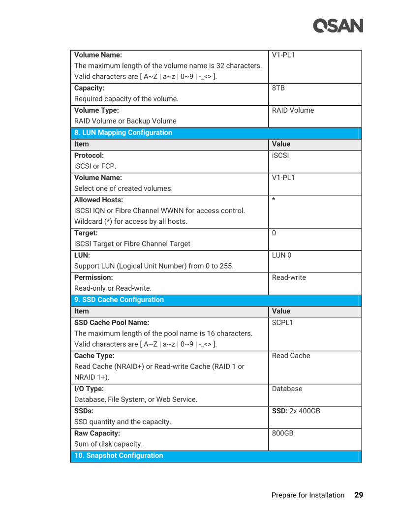
Prepare for Installation 29
Volume Name:
The maximum length of the volume name is 32 characters.
Valid characters are [ A~Z | a~z | 0~9 | -_<> ].
V1-PL1
Capacity:
Required capacity of the volume.
8TB
Volume Type:
RAID Volume or Backup Volume
RAID Volume
8. LUN Mapping Configuration
Item Value
Protocol:
iSCSI or FCP.
iSCSI
Volume Name:
Select one of created volumes.
V1-PL1
Allowed Hosts:
iSCSI IQN or Fibre Channel WWNN for access control.
Wildcard (*) for access by all hosts.
*
Target:
iSCSI Target or Fibre Channel Target
0
LUN:
Support LUN (Logical Unit Number) from 0 to 255.
LUN 0
Permission:
Read-only or Read-write.
Read-write
9. SSD Cache Configuration
Item Value
SSD Cache Pool Name:
The maximum length of the pool name is 16 characters.
Valid characters are [ A~Z | a~z | 0~9 | -_<> ].
SCPL1
Cache Type:
Read Cache (NRAID+) or Read-write Cache (RAID 1 or
NRAID 1+).
Read Cache
I/O Type:
Database, File System, or Web Service.
Database
SSDs:
SSD quantity and the capacity.
SSD: 2x 400GB
Raw Capacity:
Sum of disk capacity.
800GB
10. Snapshot Configuration

30 © Copyright 2018 QSAN Technology, Inc. All Right Reserved.
Item Value
Volume Name:
Select one of created volumes.
V1-PL1
Snapshot Space:
Reserved snapshot space for the volume.
1.6TB
Snapshot Name:
The maximum length of the snapshot name is 32
characters. Valid characters are [ A~Z | a~z | 0~9 | -_<> ].
Snap-V1-PL1
Schedule Snapshots: (optional)
Define the cycle of snapshots.
Daily 00:00
11. Local Clone Configuration
Item Value
Source Volume Name:
Select one of created volume for source.
V1-PL1
Source Volume Capacity:
Check the capacity of source volume.
8TB
Target Volume Name:
Select one of created volume for target.
T1-PL1
Target Volume Capacity:
Check the capacity of target volume.
8TB
Schedule Local Clones: (optional)
Define the cycle of local clones.
Daily 01:00
12. Remote Replication Configuration
Item Value
Source Volume Name:
Select one of created volume for source.
V1-PL1
Source Volume Capacity:
Check the capacity of source volume.
8TB
Source iSCSI Port:
iSCSI port of source unit. It can be auto or dedicated iSCSI
port.
Auto
Target iSCSI Port IP Addresses:
iSCSI port IP addresses of target unit.
Target Controller 1 Controller 2 (optional)
IP Address 10.10.100.1 10.10.101.1
Target CHAP Username: (optional)
CHAP username. The maximum length of the username is
chap2

Prepare for Installation 31
223 characters. Valid characters are [ A~Z | a~z | 0~9 |
~!@#%^&*_-+=|(){}[]:;<>.?/ ].
Target CHAP Password: (optional)
CHAP password. The length of the password is between 12
to 16 characters. Valid characters are [ A~Z | a~z | 0~9 |
~!@#$%^&*_-+=`|\(){}[]:;”’<>,.?/ ].
123456789012
Target Volume Name:
Select one of created volume for target.
RT1-PL1
Target Volume Capacity:
Check the capacity of target volume.
8TB
Schedule Remote Replications: (optional)
Define the cycle of remote replications.
Daily 02:00
Traffic Shaping for Peak Hour: (optional)
Limit the transfer rate at peak hour.
100MB
Traffic Shaping for Off-peak Hour: (optional)
Limit the transfer rate at off-peak hour.
500MB
Off-peak Hour: (optional)
Define the off-peak hours.
Mon. ~ Fri. PM10:00 ~
AM06:59
Sat. ~ Sun. AM00:00 ~
PM23:59

32 © Copyright 2018 QSAN Technology, Inc. All Right Reserved.
3. Getting Started
After completing the configuration planning, it’s time to power on the system, find your
system and log into SANOS (SAN operating system). This chapter explains how to discover
the SAN storage system and how to sign into SANOS.
3.1. Power on the Storage System
Before you power on the system, we assume that you have followed the following hardware
installation document to finish the hardware installation.
XCubeSAN QIG (Quick Installation Guide)
XCubeSAN Hardware Owner’s Manual
TIP:
Please double check all the cables (including power cords, Ethernet, fibre
channel, and SAS cables) are connected properly, especially network
cable connects to the management port. If everything is ready, now you
can power on the system.
3.2. Discover the SAN Storage System
The default setting for the management IP address is DHCP. For users who are going to
install at the first time, we provide the QFinder Java utility to search for QSAN products on
the network and aid quick access to the login page of the SANOS web interface.
3.2.1. QFinder Utility
QFinder utility provides to search QSAN products on LAN. You can discover the
management IP addresses of the storage systems via this utility. Please download QFinder
utility from the following website.
https://qsan.com/QFinder
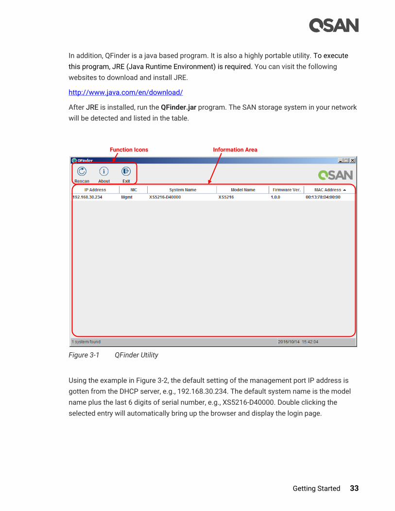
Getting Started 33
In addition, QFinder is a java based program. It is also a highly portable utility. To execute
this program, JRE (Java Runtime Environment) is required. You can visit the following
websites to download and install JRE.
http://www.java.com/en/download/
After JRE is installed, run the QFinder.jar program. The SAN storage system in your network
will be detected and listed in the table.
Figure 3-1 QFinder Utility
Using the example in Figure 3-2, the default setting of the management port IP address is
gotten from the DHCP server, e.g., 192.168.30.234. The default system name is the model
name plus the last 6 digits of serial number, e.g., XS5216-D40000. Double clicking the
selected entry will automatically bring up the browser and display the login page.
Function Icons Information Area

34 © Copyright 2018 QSAN Technology, Inc. All Right Reserved.
TIP:
QFinder utility works in the following network environments:
Both the management port of the SAN storage system and the
management computer are both on the same subnet domain of the
LAN.
The LAN works with or without DHCP server.
If the LAN doesn’t have a DHCP server, it still can work on zero-
configuration networking. The management port will be assigned a fix
IP address: 169.254.1.234/16. So you can configure the IP address of
your management computer to the same subnet domain of the
storage system, e.g.: 169.254.1.1/16. Then open a browser and enter
http://169.254.1.234 to go into the login page. For more information
about zero configuration, please refer to:
https://en.wikipedia.org/wiki/Zero-configuration_networking
3.3. Initial Setup
The Initial configuration wizard will guide the first time user to initialize and setup the
system quickly. After discovering the storage system, please follow the steps to complete
the initial configuration.
Figure 3-2 Login Page of web UI
1. To access the SANOS web interface, you have to enter a username and password. The
initial defaults for administrator login are:
Default System Name

Getting Started 35
。 Username: admin
。 Password: 1234
TIP:
For existing users who are experienced, the Initial configuration wizard
will not be shown again when you login next time, unless the system is
Reset to Defaults. You may skip this section to start the operations of
web UI in next chapter.
You can execute Reset to Defaults function in SYSTEM SETTINGS ->
Maintenance -> Reset to Defaults. Please refer to the chapter 6.5.5, Reset
to Factory Default section for more details.
Figure 3-3 Initial Configuration Step 1
2. Enter a System Name, for security reason, it’s highly recommended to change system
name. The maximum length of the system name is 32 characters. Valid characters are
[ A~Z | a~z | 0~9 | -_ ].

36 © Copyright 2018 QSAN Technology, Inc. All Right Reserved.
3. Change Admin Password, The maximum length of the password is 12 characters. Valid
characters are [ A~Z | a~z | 0~9 | ~!@#$%^&*_-+=`|\(){}[]:;"'<>,.?/ ].
4. Set the local Date and Time. Date and time can be set by manually or synchronized with
a NTP (Network Time Protocol) server.
5. Select a Time Zone depending on your location.
6. Click the Next button to proceed.
Figure 3-4 Initial Configuration Step 2
7. Assign an IP address for the management port by DHCP, BOOTP, or Static IP Address.
Getting Started 37
INFORMATION:
DHCP: The Dynamic Host Configuration Protocol is a standardized
network protocol used on IP (Internet Protocol) networks for dynamically
distributing network configuration parameters, such as IP addresses for
interfaces and services. With DHCP, computers request IP addresses and
networking parameters automatically from a DHCP server, reducing the
need for a network administrator or a user to configure these settings
manually.
BOOTP: Similar to DHCP, the Bootstrap Protocol is also a computer
networking protocol used in Internet Protocol networks to automatically
assign an IP address to network devices from a configuration server.
While some parts of BOOTP have been effectively superseded by the
DHCP, which adds the feature of leases, parts of BOOTP are used to
provide service to the DHCP protocol. DHCP servers also provide legacy
BOOTP functionality.
8. Assign a DNS Server Address. DNS (Domain Name System) provides a means to
translate FQDN (Fully Qualified Domain Name) to IP address. Some notification services
require DNS settings.
9. Click Next button to proceed.
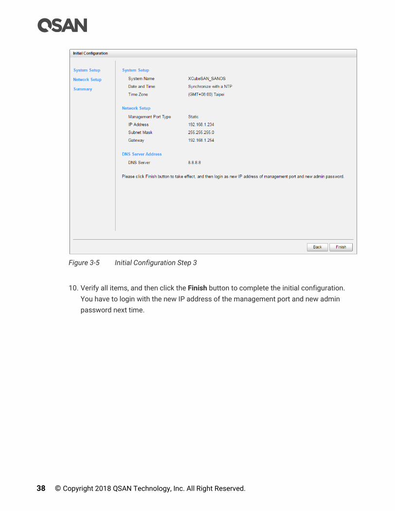
38 © Copyright 2018 QSAN Technology, Inc. All Right Reserved.
Figure 3-5 Initial Configuration Step 3
10. Verify all items, and then click the Finish button to complete the initial configuration.
You have to login with the new IP address of the management port and new admin
password next time.

SANOS User Interface 39
4. SANOS User Interface
This chapter illustrates the web user interface of SANOS and provides a brief introduction to
the SANOS 4.0 desktop function menus.
4.1. Accessing the Management Web UI
To access the management web user interface, open a supported web browser and enter
the management IP address or Hostname of the system. The login panel is displayed, as
shown in Figure 4-1.
Figure 4-1 Login Page of web UI
To access the web user interface, you have to enter a username and password.
Username: admin
Password: <Your Password>
TIP:
Supported web browsers:
Google Chrome 45 or later.
Mozilla Firefox 45 or later.
Microsoft Internet Explorer 10 or later.
Apple Safari 8 or later.

40 © Copyright 2018 QSAN Technology, Inc. All Right Reserved.
4.2. SANOS 4.0 Desktop Panel
When the password has been verified, the home page is displayed. As shown in Figure 4-2,
the SANOS 4.0 desktop panel has three main sections:
Function Menus and Submenus
Function Tabs
Main Working Area
Figure 4-2 SANOS 4.0 Desktop Panel
All function menus are listed at the left side of the window. They are grouping by function
icon and uppercase letter such as DASHBOARD, SYSTEM SETTINGS …etc. The following is
the second level function submenus such as General Settings, Management Port …etc. This
provides an efficient and quick mechanism for navigation.
Click a second level function submenu will appear the related user interface in main working
area. Some function submenus have their sub functions and display at the top of function
tabs. You may see all functions in Table 4-1.
The top-right corner displays a Logout button.
Function Menus & Submenus
Main Working Area Function Tabs

SANOS User Interface 41
TIP:
For security reasons, always logout when you finish working in SANOS
4.3. Function Menus
The following table shows all function menus and their function tabs for reference.
Table 4-1 SANOS 4.0 Function Menus Function Menus Function Tabs
DASHBOARD
Dashboard Dashboard
Hardware Monitoring Hardware Monitoring
SYSTEM SETTING
General Settings General Settings
Management Port Management Port
Power Settings Boot Management | Cache to Flash | UPS
Notifications Email | Alert | SNMP
Maintenance System Information | Update | Firmware
Synchronization | System Identification | Reset
to Defaults | Configuration Backup | Volume
Restoration | Reboot and Shutdown
Disk Encryption Authentication Key | SEDs
HOST CONNECTIVITY
Overview Overview
iSCSI Ports iSCSI Ports | iSCSI Settings | iSCSI Targets |
CHAP Accounts | Active Sessions
Fibre Channel Ports Fibre Channel Ports
STORAGE MANAGEMENT
Disks Disks | Disk Settings
Pools Pools | Auto Tiering

42 © Copyright 2018 QSAN Technology, Inc. All Right Reserved.
Volumes Volumes
LUN Mappings LUN Mappings
SSD Cache SSD Cache Pools | SSD Cache Statistics
DATA BACKUP
Snapshots Snapshots
Remote Replications Remote Replications
VIRTUALIZATION
VMware VMware
Microsoft Hyper-V
Citrix Citrix
MONITORING
Log Center Event Logs
Enclosures Hardware Monitoring | SES
Performance Disk | Volume | iSCSI | Fibre Channel
The following describes a brief introduction of desktop function menus.
4.3.1. Dashboard Menu
The DASHBOARD menu provides access to function menus of Dashboard and Hardware
Monitoring.
Dashboard
Select Dashboard function menu provides summary of the overall system. For more
information, please refer to the chapter 5.1, Dashboard section in the Dashboard chapter.
Hardware Monitoring
Select Hardware Monitoring function menu provides summary enclosure information. For
more information, please refer to the chapter 5.2, Hardware Monitoring section in the
Dashboard chapter.
SANOS User Interface 43
4.3.2. System Settings Menu
The SYSTEM SETTINGS menu provides access to function menus of General, Management
Port, Power, Notification, and Maintenance.
General Settings
Select General Settings function menu to setup general system settings. For more
information, please refer to the chapter 6.1, General System Settings section in the System
Settings chapter.
Management Port
Select Management Port function menu to setup IP address and DNS settings of
management port. For more information, please refer to the chapter 6.2, Management Port
Settings section in the System Settings chapter.
Power Settings
Select Power Settings function menu to setup boot management which includes auto
shutdown, wake on LAN, and wake on SAS …etc., view the status of cache to flash, and
setup UPS for power outage. For more information, please refer to the chapter 6.3, Power
Settings section in the System Settings chapter.
Notifications
Select Notifications function menu to setup notification settings of email, syslog, popup
alert, LCM alert, and SNMP trap. For more information, please refer to the chapter 6.4,
Notification Settings section in the System Settings chapter.
Maintenance
Select Maintenance function menu to view system information, update system firmware
and check firmware synchronization, system identification, reset to system defaults, import
and export configuration files, restore volumes if an accidental delete occurs, reboot and
shutdown. For more information, please refer to the chapter 6.5, Maintenance section in the
System Settings chapter.
Disk Encryption
Select Disk Encryption function menu to setup the authentication key and configure SEDs.
For more information, please refer to the chapter 14, SED and ISE Support chapter.

44 © Copyright 2018 QSAN Technology, Inc. All Right Reserved.
4.3.3. Host Configuration Menu
The HOST CONFIGURATION menu provides access to function menus of Overview, iSCSI
Port, and Fibre Channel Ports which is visible when fibre channel host cards are installed.
Overview
Select Overview function menu to view all host connectivity which includes status and
settings of all host cards. For more information, please refer to the chapter 7.2, Host
Connectivity Overview section in the Host Configuration chapter.
iSCSI Ports
Select iSCSI Ports function menu to setup iSCSI port settings, including iSCSI port IP
address, link aggregation, VLAN ID, jumbo frame, iSNS server, iSCSI targets, CHAP accounts,
and view iSCSI active sessions. For more information, please refer to the chapter 7.3,
Configure for iSCSI Connectivity section in the Host Configuration chapter.
Fibre Channel Ports
Select Fibre Channel function menu to setup fibre channel port settings, including link
speed, topology, target configuration, and clear counters of fibre channel statistics. For
more information, please refer to the chapter 7.4, Configure for Fibre Channel Connectivity
section in the Host Configuration chapter.
4.3.4. Storage Management Menu
The STORAGE MANAGEMENT menu provides access to function menus of Disks, Pools,
Volumes, and Mappings.
Disks
Select Disks function menu to view status of disk drives and S.M.A.R.T. (Self-Monitoring
Analysis and Reporting Technology) information. For more information, please refer to the
chapter 8.3, Working with Disk Drives section in the Storage Management chapter.
Pools
Select Pools function menu to configure storage pools. For more information, please refer
to the chapter 8.4, Configuring Thick Provisioning Pools section in the Storage Management

SANOS User Interface 45
chapter, chapter 9.3, Configuring Thin Provisioning Pools section in the Thin Provisioning
chapter, chapter 11.3, Configuring Auto Tiering Pools section in the Auto Tiering chapter.
Volumes
Select Volumes function menu to configure volumes and manage clone tasks. For more
information, please refer to the chapter 8.5, Configuring Volumes section in the Storage
Management chapter and the chapter 12.2, Managing Local Clones section in the Data
Backup chapter.
LUN Mappings
Select LUN Mappings function menu to configure LUN mappings. For more information,
please refer to the chapter 8.6, Configuring LUN Mappings section in the Storage
Management chapter.
SSD Cache
Select SSD Cache function menu to configure SSD cache pools. For more information,
please refer to the chapter 10.3, Configuring SSD Cache section in SSD Cache chapter.
4.3.5. Data Backup Menu
The DATA BACKUP menu provides access to function menus of Snapshots and
Replications.
Snapshots
Select Snapshots function menu to manage snapshots, including setting up snapshot space,
taking snapshots, rollback to a snapshot, and scheduling snapshots. For more information,
please refer to the chapter 12.1, Managing Snapshots section in the Data Backup chapter.
Replications
Select Replications function menu to manage remote replications, including setup
replication tasks, schedule replication tasks, configure shaping settings. For more
information, please refer to the chapter 12.3, Managing Remote Replications section in the
Data Backup chapter.

46 © Copyright 2018 QSAN Technology, Inc. All Right Reserved.
4.3.6. Virtualization Menu
The VIRTUALIZATION menu provides access to function menus of VMware, Microsoft, and
Citrix.
VMware
Provide information of supported VMware integration of storage, such as VAAI (VMware
vSphere Storage APIs for Array Integration).
Microsoft
Provide information of supported Microsoft Windows feature of storage, such as ODX
(Offloaded Data Transfer).
Citrix
Provide information of Citrix XenServer platform and its compatible version.
4.3.7. Monitoring Menu
The MONITORING menu provides access to function menus of Log Center, Enclosure, and
Performance.
Log Center
Select Log Center function menu to view event logs, download event logs, or clear event
logs. Also mute buzzer if system happens alerts. For more information, please refer to the
chapter 13.1, Log Center section in the Monitoring chapter.
Enclosures
Select Enclosures function menu to view hardware monitor status and enable SES (SCSI
Enclosure Services). For more information, please refer to the chapter 13.2, Hardware
Monitor section in the Monitoring chapter.
Performance
Select Performance function menu to view system performance. For more information,
please refer to the chapter 13.3, Performance Monitor section in the Monitoring chapter.
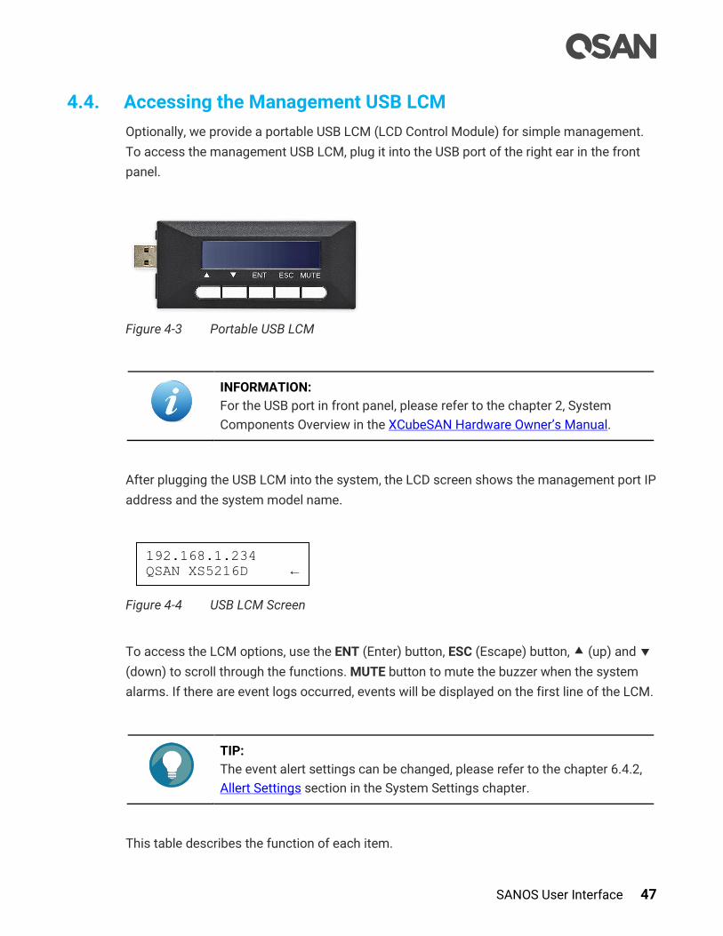
SANOS User Interface 47
4.4. Accessing the Management USB LCM
Optionally, we provide a portable USB LCM (LCD Control Module) for simple management.
To access the management USB LCM, plug it into the USB port of the right ear in the front
panel.
Figure 4-3 Portable USB LCM
INFORMATION:
For the USB port in front panel, please refer to the chapter 2, System
Components Overview in the XCubeSAN Hardware Owner’s Manual.
After plugging the USB LCM into the system, the LCD screen shows the management port IP
address and the system model name.
Figure 4-4 USB LCM Screen
To access the LCM options, use the ENT (Enter) button, ESC (Escape) button, (up) and
(down) to scroll through the functions. MUTE button to mute the buzzer when the system
alarms. If there are event logs occurred, events will be displayed on the first line of the LCM.
TIP:
The event alert settings can be changed, please refer to the chapter 6.4.2,
Allert Settings section in the System Settings chapter.
This table describes the function of each item.
192.168.1.234
QSAN XS5216D ←

48 © Copyright 2018 QSAN Technology, Inc. All Right Reserved.
Table 4-2 USB LCM Function List
Function Description
System Info. Display system information including firmware version and memory
size.
Reset/Shutdown Reset or shutdown the system.
View IP Setting Display current IP address, subnet mask, and gateway.
Change IP
Config
Set IP address, subnet mask, and gateway. There are three options of
DHCP, BOOTP, or static IP address.
Enc.
Management
Show the enclosure data of disk drive temperature, fan status, and
power supply status.
Reset to Default Reset the system to default settings. The default settings are:
Reset Management Port IP address to DHCP, and then fix IP
address: 169.254.1.234/16.
Reset admin’s Password to 1234.
Reset System Name to model name plus the last 6 digits of serial
number. For example: XS5216-123456.
Reset IP addresses of all iSCSI Ports to 192.168.1.1,
192.168.2.1, … etc.
Reset link speed of all Fibre Channel Ports to Automatic.
Clear all access control settings of the host connectivity.
INFORMATION:
DHCP: The Dynamic Host Configuration Protocol is a standardized
network protocol used on IP (Internet Protocol) networks for dynamically
distributing network configuration parameters, such as IP addresses for
interfaces and services. With DHCP, computers request IP addresses and
networking parameters automatically from a DHCP server, reducing the
need for a network administrator or a user to configure these settings
manually.
BOOTP: Similar to DHCP, the Bootstrap Protocol is also a computer
networking protocol used in Internet Protocol networks to automatically
assign an IP address to network devices from a configuration server.
While some parts of BOOTP have been effectively superseded by the
DHCP, which adds the feature of leases, parts of BOOTP are used to
provide service to the DHCP protocol. DHCP servers also provide legacy
BOOTP functionality.
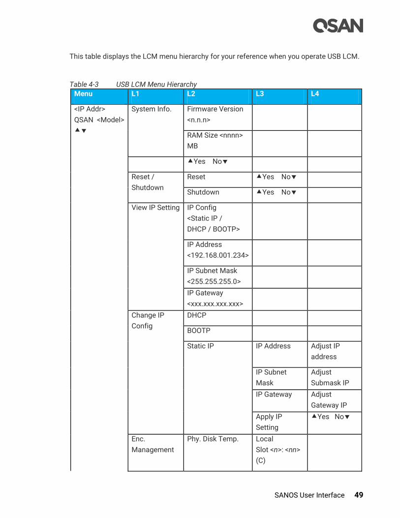
SANOS User Interface 49
This table displays the LCM menu hierarchy for your reference when you operate USB LCM.
Table 4-3 USB LCM Menu Hierarchy
Menu L1 L2 L3 L4
<IP Addr>
QSAN <Model>
System Info. Firmware Version
<n.n.n>
RAM Size <nnnn>
MB
Yes No
Reset /
Shutdown
Reset Yes No
Shutdown Yes No
View IP Setting IP Config
<Static IP /
DHCP / BOOTP>
IP Address
<192.168.001.234>
IP Subnet Mask
<255.255.255.0>
IP Gateway
<xxx.xxx.xxx.xxx>
Change IP
Config
DHCP
BOOTP
Static IP IP Address Adjust IP
address
IP Subnet
Mask
Adjust
Submask IP
IP Gateway Adjust
Gateway IP
Apply IP
Setting
Yes No
Enc.
Management
Phy. Disk Temp. Local
Slot <n>: <nn>
(C)

50 © Copyright 2018 QSAN Technology, Inc. All Right Reserved.
Cooling Local
FAN<n>:
<nnnnn> RPM
Power Supply Local
PSU<n>:
<status>
Reset to
Default
Yes No
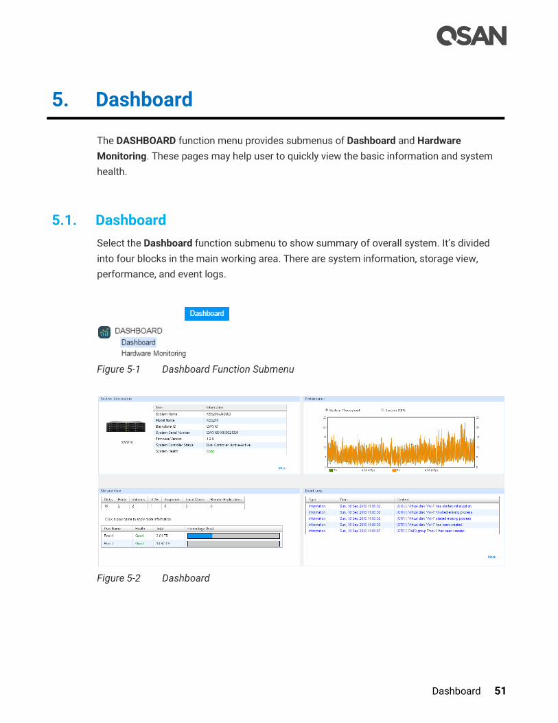
Dashboard 51
5. Dashboard
The DASHBOARD function menu provides submenus of Dashboard and Hardware
Monitoring. These pages may help user to quickly view the basic information and system
health.
5.1. Dashboard
Select the Dashboard function submenu to show summary of overall system. It’s divided
into four blocks in the main working area. There are system information, storage view,
performance, and event logs.
Figure 5-1 Dashboard Function Submenu
Figure 5-2 Dashboard

52 © Copyright 2018 QSAN Technology, Inc. All Right Reserved.
System Information
The system information block displays the basic information of the system. In addition,
clicking More… will pop up a window for more details.
Figure 5-3 System Information Block in the Dashboard
This table shows the column descriptions.
Table 5-1 System Information Block Descriptions
Column Name Description
System
Availability
Status
The status of system availability:
Dual Controller, Active/Active: Dual controllers and expansion
units are in normal stage.
Dual Controller, Degraded: In dual controller mode, one controller
or one of expansion unit fails or they have been plugged out.
Please replace or insert a good controller.
Dual Controller, Lockdown: In dual controller mode, the
configurations of two controllers are different, including the
memory capacity, host cards, and controller firmware version.
Please check the hardware configurations of two controllers or
execute firmware synchronization.
Single Controller: Single controller mode.
System Health The status of system health:
Good: The system is good.
Fan Fault: A fan module has failed or is no longer connected..
PSU Fault: A power supply has failed or is no longer connected.
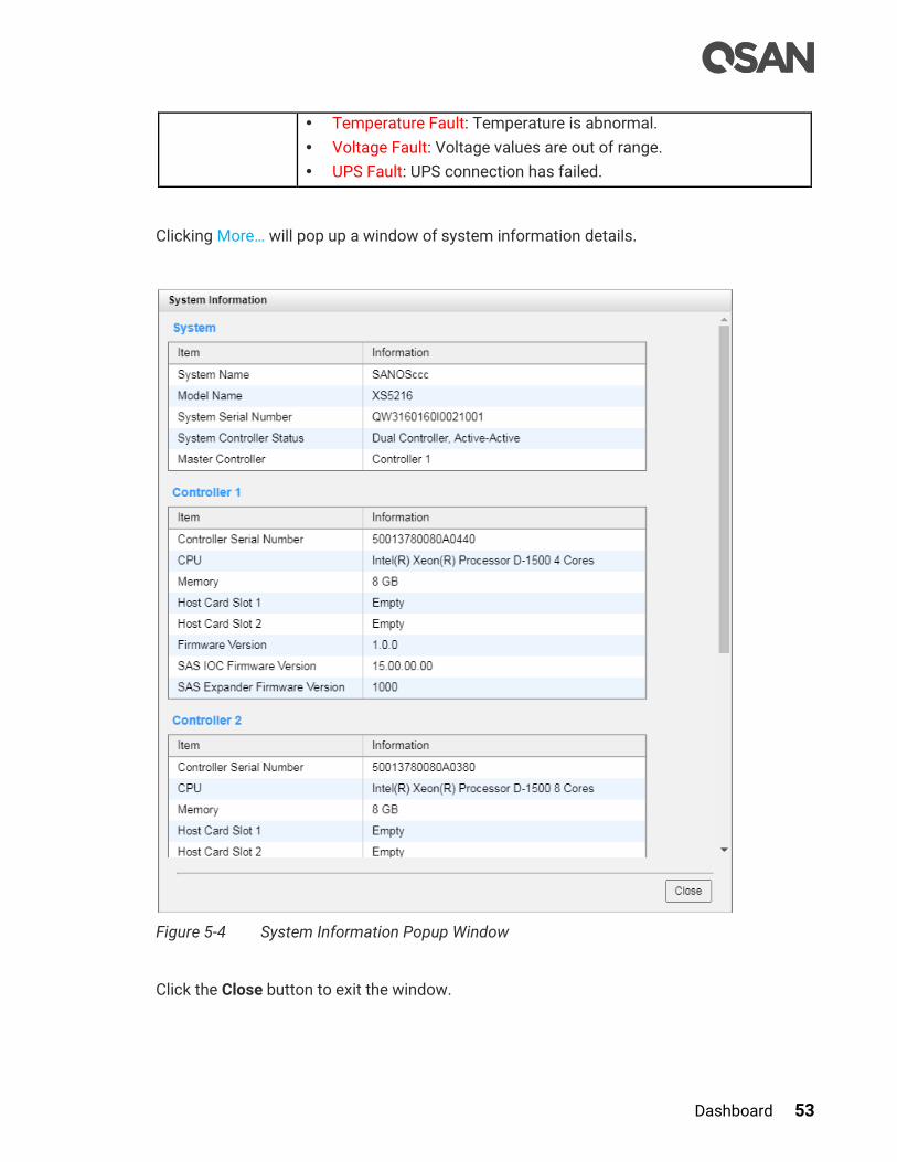
Dashboard 53
Temperature Fault: Temperature is abnormal.
Voltage Fault: Voltage values are out of range.
UPS Fault: UPS connection has failed.
Clicking More… will pop up a window of system information details.
Figure 5-4 System Information Popup Window
Click the Close button to exit the window.

54 © Copyright 2018 QSAN Technology, Inc. All Right Reserved.
Storage View
The storage view block displays the basic information of storage. In addition, clicking pool
column will pop up a window for more details.
Figure 5-5 System View Block in the Dashboard
The top table displays sum of disks, pools, volumes, LUN mappings, snapshots, clones, and
remote replications in system. The following table displays all created pools and its basic
information.
Table 5-2 Storage View Block Descriptions
Column Name Description
Name Pool name.
Health The health of the pool:
Good: The pool is good.
Failed: The pool is failed.
Degraded: The pool is not healthy and not completed. The reason
could be lack of disk(s) or have failed disk.
Total Total capacity of the pool.
Percentage Used Mouse over the Blue block will display the percentage of used. And
the Gray block will display the percentage of available.
Click any one of the pool names such as Pool-1 in Figure 5-4 will pop up the detailed pool
information.

Dashboard 55
Figure 5-6 Pool Information Popup Window
This table shows the column descriptions.
Table 5-3 Volume Column Descriptions
Column Name Description
Name Volume name.
Health The health of the volume:
Optimal: the volume is working well and there is no failed disk in
the RG.
Failed: the pool disk of the VD has single or multiple failed disks
than its RAID level can recover from data loss.
Degraded: At least one disk from the RG of the Volume is failed or

56 © Copyright 2018 QSAN Technology, Inc. All Right Reserved.
plugged out.
Non-optimal: the volume has experienced recoverable read errors.
After passing parity check, the health will become Optimal.
Capacity Total capacity of the volume.
Used Used capacity of the volume.
Used % Used percentage of the volume.
Snapshot space Used snapshot space / Total snapshot space. The first capacity is
current used snapshot space, and the second capacity is reserved
total snapshot space.
Snapshots The quantity of snapshot of the volume.
Table 5-4 Disk Group Column Descriptions
Column Name Description
No The number of disk group.
Status The status of the disk group:
Online: The disk group is online.
Offline: The disk group is offline.
Rebuilding: The disk group is being rebuilt.
Migrating: The disk group is being migrated.
Relocating: The disk group is being relocated.
EE Rebuilding: The disk group is being RAID EE rebuilt.
Health The health of the disk group:
Good: The disk group is good.
Failed: The disk group fails.
Degraded: The pool is not healthy and not complete. The reason
could be missing or failed disks.
Total Total capacity of the disk group.
Free Free capacity of the disk group.
Disks Used The quantity of disk drives in the disk group.
Location Disk location represents in Enclosure ID:Slot.
Table 5-5 Disk Column Descriptions
Column Name Description
Enclosure ID The enclosure ID.
Slot The position of the disk drive.
Status The status of the disk drive:

Dashboard 57
Online: The disk drive is online.
Missing: The disk drive is missing in the pool.
Rebuilding: The disk drive is being rebuilt.
Transitioning: The disk drive is being migrated or is replaced by
another disk when rebuilding occurs.
Scrubbing: The disk drive is being scrubbed.
Check Done: The disk drive has been checked the disk health.
Copying Back: The disk drive is being copied back.
Health The health of the disk drive:
Good: The disk drive is good.
Failed: The disk drive is failed.
Error Alert: S.M.A.R.T. error alerts.
Read Errors: The disk drive has unrecoverable read errors.
Capacity The capacity of the disk drive.
Disk Type The type of the disk drive:
[ SAS HDD | NL-SAS HDD | SAS SSD | SATA SSD ]
[ 12.0Gb/s | 6.0Gb/s | 3.0Gb/s | 1.5Gb/s ]
Manufacturer The manufacturer of the disk drive.
Model The model name of disk drive.
Click the Close button to exit the window.
Performance
The performance block displays the system throughput or system IOPS of all front-end
ports for reference.
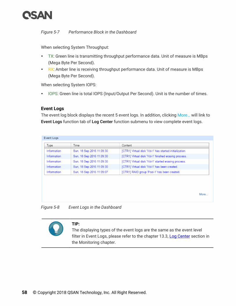
58 © Copyright 2018 QSAN Technology, Inc. All Right Reserved.
Figure 5-7 Performance Block in the Dashboard
When selecting System Throughput:
TX: Green line is transmitting throughput performance data. Unit of measure is MBps
(Mega Byte Per Second).
RX: Amber line is receiving throughput performance data. Unit of measure is MBps
(Mega Byte Per Second).
When selecting System IOPS:
IOPS: Green line is total IOPS (Input/Output Per Second). Unit is the number of times.
Event Logs
The event log block displays the recent 5 event logs. In addition, clicking More… will link to
Event Logs function tab of Log Center function submenu to view complete event logs.
Figure 5-8 Event Logs in the Dashboard
TIP:
The displaying types of the event logs are the same as the event level
filter in Event Logs, please refer to the chapter 13.3, Log Center section in
the Monitoring chapter.

Dashboard 59
5.2. Hardware Monitoring
Select the Hardware Monitoring function submenu to show summary status of all
enclosures. There are current voltage, temperature, status of fan module, and power supply.
In addition, clicking More… will pop up a window for more details.
Figure 5-9 Hardware Monitoring Function Submenu
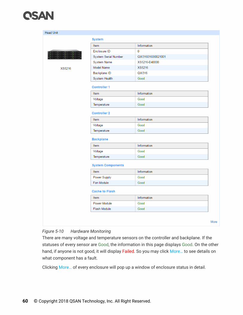
60 © Copyright 2018 QSAN Technology, Inc. All Right Reserved.
Figure 5-10 Hardware Monitoring
There are many voltage and temperature sensors on the controller and backplane. If the
statuses of every sensor are Good, the information in this page displays Good. On the other
hand, if anyone is not good, it will display Failed. So you may click More… to see details on
what component has a fault.
Clicking More… of every enclosure will pop up a window of enclosure status in detail.

Dashboard 61
Figure 5-11 Head Unit Popup Window
Click the Close button to exit the window.
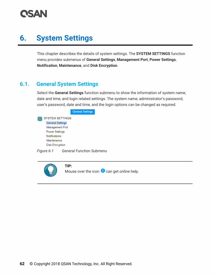
62 © Copyright 2018 QSAN Technology, Inc. All Right Reserved.
6. System Settings
This chapter describes the details of system settings. The SYSTEM SETTINGS function
menu provides submenus of General Settings, Management Port, Power Settings,
Notification, Maintenance, and Disk Encryption.
6.1. General System Settings
Select the General Settings function submenu to show the information of system name,
date and time, and login related settings. The system name, administrator’s password,
user’s password, date and time, and the login options can be changed as required.
Figure 6-1 General Function Submenu
TIP:
Mouse over the icon can get online help.
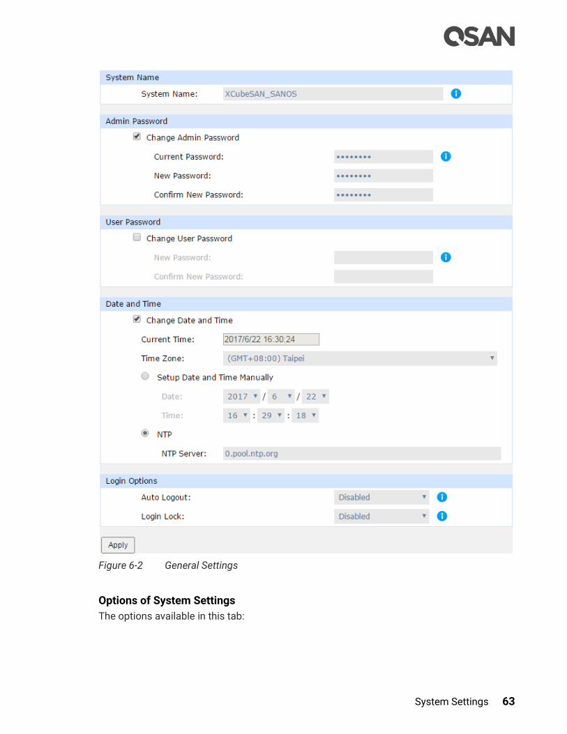
System Settings 63
Figure 6-2 General Settings
Options of System Settings
The options available in this tab:
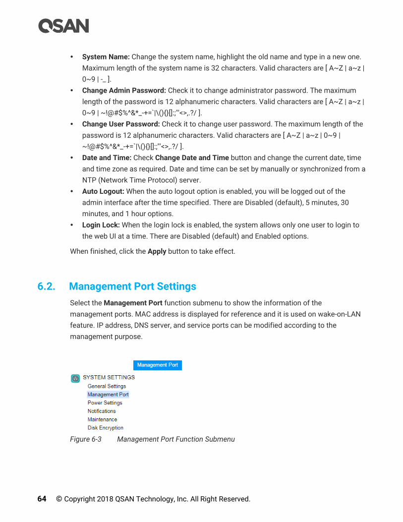
64 © Copyright 2018 QSAN Technology, Inc. All Right Reserved.
System Name: Change the system name, highlight the old name and type in a new one.
Maximum length of the system name is 32 characters. Valid characters are [ A~Z | a~z |
0~9 | -_ ].
Change Admin Password: Check it to change administrator password. The maximum
length of the password is 12 alphanumeric characters. Valid characters are [ A~Z | a~z |
0~9 | ~!@#$%^&*_-+=`|\(){}[]:;"'<>,.?/ ].
Change User Password: Check it to change user password. The maximum length of the
password is 12 alphanumeric characters. Valid characters are [ A~Z | a~z | 0~9 |
~!@#$%^&*_-+=`|\(){}[]:;"'<>,.?/ ].
Date and Time: Check Change Date and Time button and change the current date, time
and time zone as required. Date and time can be set by manually or synchronized from a
NTP (Network Time Protocol) server.
Auto Logout: When the auto logout option is enabled, you will be logged out of the
admin interface after the time specified. There are Disabled (default), 5 minutes, 30
minutes, and 1 hour options.
Login Lock: When the login lock is enabled, the system allows only one user to login to
the web UI at a time. There are Disabled (default) and Enabled options.
When finished, click the Apply button to take effect.
6.2. Management Port Settings
Select the Management Port function submenu to show the information of the
management ports. MAC address is displayed for reference and it is used on wake-on-LAN
feature. IP address, DNS server, and service ports can be modified according to the
management purpose.
Figure 6-3 Management Port Function Submenu

System Settings 65
Figure 6-4 Management Port settings
Options of Management Port Settings
The options available in this tab:
Enable Dual Management Ports: This is for dual controller models. When the setting is
enabled, both management ports of the controllers have their own IP addresses and
MAC addresses, and both are active. If the setting is disabled, only the management
port of the master controller is active, the other one is on standby. Both controller
management ports share the same IP address and MAC address. The management port

66 © Copyright 2018 QSAN Technology, Inc. All Right Reserved.
fails over to the slave controller when the master controller goes offline, either planned
or unplanned.
INFORMATION:
For deployment of management ports, please refer to the chapter 4
Deployment Types and Cabling in the XCubeSAN Hardware Owner’s
Manual.
MAC Address: Display the MAC address of the management port.
IP Address: The option can change IP address for remote administration usage. There
are three options for DHCP, BOOTP, or Static IP Address.
INFORMATION:
DHCP: The Dynamic Host Configuration Protocol is a standardized
network protocol used on IP (Internet Protocol) networks for dynamically
distributing network configuration parameters, such as IP addresses for
interfaces and services. With DHCP, computers request IP addresses and
networking parameters automatically from a DHCP server, reducing the
need for a network administrator or a user to configure these settings
manually.
BOOTP: Similar to DHCP, the Bootstrap Protocol is also a computer
networking protocol used in Internet Protocol networks to automatically
assign an IP address to network devices from a configuration server.
While some parts of BOOTP have been effectively superseded by the
DHCP, which adds the feature of leases, parts of BOOTP are used to
provide service to the DHCP protocol. DHCP servers also provide legacy
BOOTP functionality.
DNS Server Address: DNS (Domain Name System) provides a means to translate FQDN
(Fully Qualified Domain Name) to IP address. Some notification services need DNS
setting. Enter an IP address of DNS server here.
Service Ports: Uncheck to disable the service ports of HTTP, HTTPS, and SSH. If the
default port numbers of the service ports are not allowed on your network environment,
they can be changed here.

System Settings 67
When finished, click the Apply button to take effect.
6.3. Power Settings
The Power Settings function submenu provides Boot Management, Cache to Flash, and
UPS function tabs to show information and configuration setup.
Figure 6-5 Power Settings Function Submenu
6.3.1. Boot Management Settings
Select the Boot Management function tab in the Power Settings function submenu to
enable or disable options about boot.
Figure 6-6 Boot Management Settings
Options of Boot Management Settings
The options available in this tab:
68 © Copyright 2018 QSAN Technology, Inc. All Right Reserved.
Enable Auto Shutdown: Check to enable auto shutdown. If enabling the setting, the
system will shutdown automatically when the internal power levels or temperature are
not within normal levels.
TIP:
For better protection and to avoid a single short period of abnormal
voltage or temperature, enabling the setting could trigger an automatic
shutdown. This is done using several sensors placed on key systems that
the system checks every 30 seconds for present voltages or
temperatures. The following items are trigger conditions.
The value of voltage or temperature is lower than Low Critical or
higher than High Critical.
When one of these sensors reports above the threshold for three
contifuous minutes, the system will be shutdown automatically.
For more information about critical values, please refer to the chapter
13.2.1, Hardware Monitoring section in the Monitoring chapter.
Enable Wake-on-LAN: Check to enable wake-on-LAN, the system will accept a magic
packet from management port to power on the system.
TIP:
To execute wake-on-LAN function, MAC address of management port is
needed. For the information of MAC address, please refer to the chapter
6.2, Management Port Settings page.
Enable Wake-on-SAS: Check to enable wake-on-SAS. If Wake-on-SAS is enabled, and
connect the XD5300 series expansion unit(s) with the proprietary Wake-on-SAS
expansion cable(s), the XD5300 series will power on or shutdown in conjunction with the
head unit.
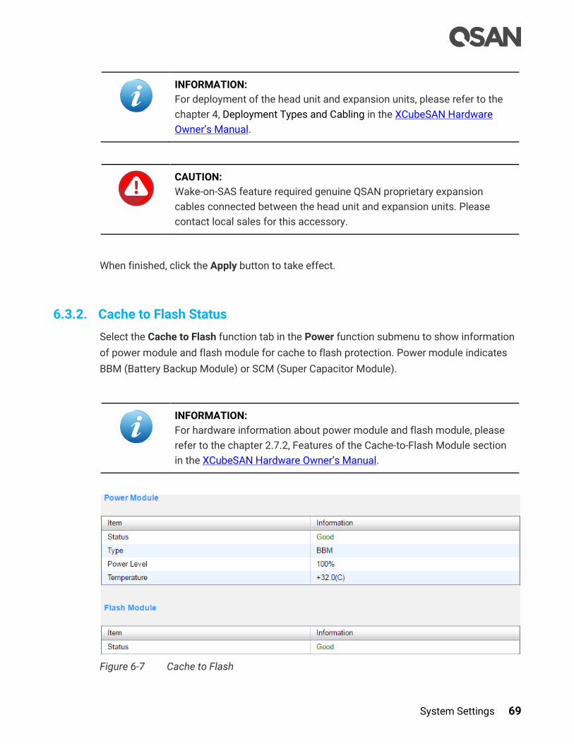
System Settings 69
INFORMATION:
For deployment of the head unit and expansion units, please refer to the
chapter 4, Deployment Types and Cabling in the XCubeSAN Hardware
Owner’s Manual.
CAUTION:
Wake-on-SAS feature required genuine QSAN proprietary expansion
cables connected between the head unit and expansion units. Please
contact local sales for this accessory.
When finished, click the Apply button to take effect.
6.3.2. Cache to Flash Status
Select the Cache to Flash function tab in the Power function submenu to show information
of power module and flash module for cache to flash protection. Power module indicates
BBM (Battery Backup Module) or SCM (Super Capacitor Module).
INFORMATION:
For hardware information about power module and flash module, please
refer to the chapter 2.7.2, Features of the Cache-to-Flash Module section
in the XCubeSAN Hardware Owner’s Manual.
Figure 6-7 Cache to Flash

70 © Copyright 2018 QSAN Technology, Inc. All Right Reserved.
This table shows the column descriptions.
Table 6-1 Power Module Column Descriptions
Column Name Description
Status The status of power module:
Good: The power module is good.
Failed: The power module is failure.
Absent: The power module is absent.
Charging: The power module is charging.
Type The type of power module:
BBM (Battery Backup Module)
SCM (Super Capacitor Module)
Power Level The power level of the module.
Temperature The temperature of the power module..
Table 6-2 Flash Module Column Descriptions
Column Name Description
Status The status of flash module:
Good: The flash module is good.
Failed: The flash module is failure.
Absent: The flash module is absent.
Detecting: The flash module is detecting.
6.3.3. UPS Settings and Status
Select the UPS function tab in the Power function submenu to enable UPS (Uninterruptible
Power Supply) settings and watch the UPS status.
INFORMATION:
For deployment of UPS, please refer to the chapter 3, Installing the
System Hardware in the XCubeSAN Hardware Owner’s Manual.
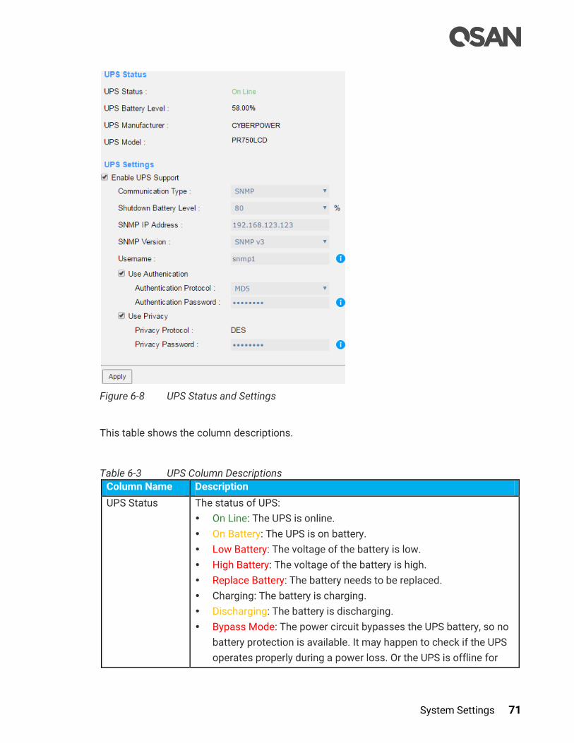
System Settings 71
Figure 6-8 UPS Status and Settings
This table shows the column descriptions.
Table 6-3 UPS Column Descriptions
Column Name Description
UPS Status The status of UPS:
On Line: The UPS is online.
On Battery: The UPS is on battery.
Low Battery: The voltage of the battery is low.
High Battery: The voltage of the battery is high.
Replace Battery: The battery needs to be replaced.
Charging: The battery is charging.
Discharging: The battery is discharging.
Bypass Mode: The power circuit bypasses the UPS battery, so no
battery protection is available. It may happen to check if the UPS
operates properly during a power loss. Or the UPS is offline for
72 © Copyright 2018 QSAN Technology, Inc. All Right Reserved.
maintenance.
Offline: UPS is offline and is not supplying power to the load.
Overloaded: UPS is overloaded. You plugged more equipments
into the UPS than it was designed to handle.
Forced Shutdown: Forced shutdown the UPS.
UPS Battery
Level
The battery level of the UPS.
UPS
Manufacturer The manufacturer of the UPS.
UPS Model The model of the UPS.
Options of UPS Settings
The options available in this tab:
Enable UPS Support: Check to enable UPS supported. Now we support network UPS via
SNMP, Serial UPS with COM port, and USB UPS.
Communication Type: Now we support network UPS via SNMP, Serial UPS with COM
port, and USB UPS.
Shutdown battery Level: If the power is shortage, the system will execute shutdown
process when reaching the UPS battery level.
If Communication Type selects SNMP:
SNMP IP Address: Enter the IP address of the network UPS via SNMP.
SNMP Version: Select SNMP supported versions: v1, v2c, or v3. Please enter community
if select SNMP v1 or v2c. If select SNMP v3, it needs more options for authentication.
Please enter a username, check to use authentication if necessary, select an
authentication protocol and enter an authentication password, check to use privacy if
necessary, the privacy protocol supports DES, and enter a privacy password.
If Communication Type selects Serial:
UPS Manufacturer: Select the UPS manufacture.
UPS Model: Select the UPS model.
When finished, click the Apply button to take effect.
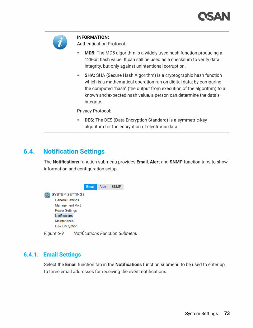
System Settings 73
INFORMATION:
Authentication Protocol:
MD5: The MD5 algorithm is a widely used hash function producing a
128-bit hash value. It can still be used as a checksum to verify data
integrity, but only against unintentional corruption.
SHA: SHA (Secure Hash Algorithm) is a cryptographic hash function
which is a mathematical operation run on digital data; by comparing
the computed "hash" (the output from execution of the algorithm) to a
known and expected hash value, a person can determine the data's
integrity.
Privacy Protocol:
DES: The DES (Data Encryption Standard) is a symmetric-key
algorithm for the encryption of electronic data.
6.4. Notification Settings
The Notifications function submenu provides Email, Alert and SNMP function tabs to show
information and configuration setup.
Figure 6-9 Notifications Function Submenu
6.4.1. Email Settings
Select the Email function tab in the Notifications function submenu to be used to enter up
to three email addresses for receiving the event notifications.

74 © Copyright 2018 QSAN Technology, Inc. All Right Reserved.
Figure 6-10 Email Settings
Options of SMTP Settings
The options available in this tab:
SMTP Server: Enter the IP address or FQDN (Fully Qualified Domain Name) of SMTP
server to deliver the notification mails.
SMTP Port: Default is port 25. You can change the SMTP port here.
Email-from Address: Enter the sender email address.
Authentication Required: Some email servers require authentication for SMTP relay.
Check to enable authentication and enter the User Name and Password.
Secure Connection: Using SSL (Secure Sockets Layer) or TLS (Transport Layer Security)
for secure connection.
Subject Prefix: The input string will be appended to the front of the email subject.
Options of Email Notification Settings
The options available in this tab:

System Settings 75
Email-to-Address: Enter the email address for receiving the event notifications. You can
also select which levels of event logs which you would like to receive. The default
setting only includes Warning and Error event logs.
TIP:
Please make sure the IP address of DNS server is well-setup in
Management Port tab. So the event notification emails can be sent
successfully. Please refer to the Management Port Settings section for
more details.
When finished, click the Send Test Email & Apply button to take effect. Or click the Reset to
Default button to reset settings.
6.4.2. Alert Settings
Select the Alert function tab in the Notifications function submenu to be used to setup
alerts via the Syslog protocol, the pop-up alerts and alerts on the front display. The device
buzzer is also managed here.
Figure 6-11 Alert Settings
76 © Copyright 2018 QSAN Technology, Inc. All Right Reserved.
Options of Alert Settings
The options available in this tab:
Syslog Server Settings: Fill in the host address and the facility for syslog service. The
default UDP port is 514. You can also check the alert levels here. Most LINUX/UNIX
systems built in syslog daemon.
Admin Interface and LCM Alerts: You can check or uncheck the alert levels which you
would like to have pop-up message in the Web UI and show on LCM.
Device Buzzer: Check it to enable the device buzzer. Uncheck it to disable device buzzer.
When finished, click the Apply button to tack effect.
TIP:
The device buzzer features are listed below:
The buzzer alarms 1 second when system boots up successfully.
The buzzer alarms continuously when there is error occurred. The
alarm will be stopped after error resolved or be muted.
The alarm will be muted automatically when the error is resolved. For
example, when a RAID 5 pool is degraded and alarm rings
immediately, user replaces one disk drive for rebuild. When the rebuild
process is done, the alarm will be muted automatically.
6.4.3. SNMP Settings
Select the SNMP function tab in the Notifications function submenu to be used to setup
SNMP (Simple Network Management Protocol) traps for alerting with event logs and also
setup SNMP server settings for client monitoring.
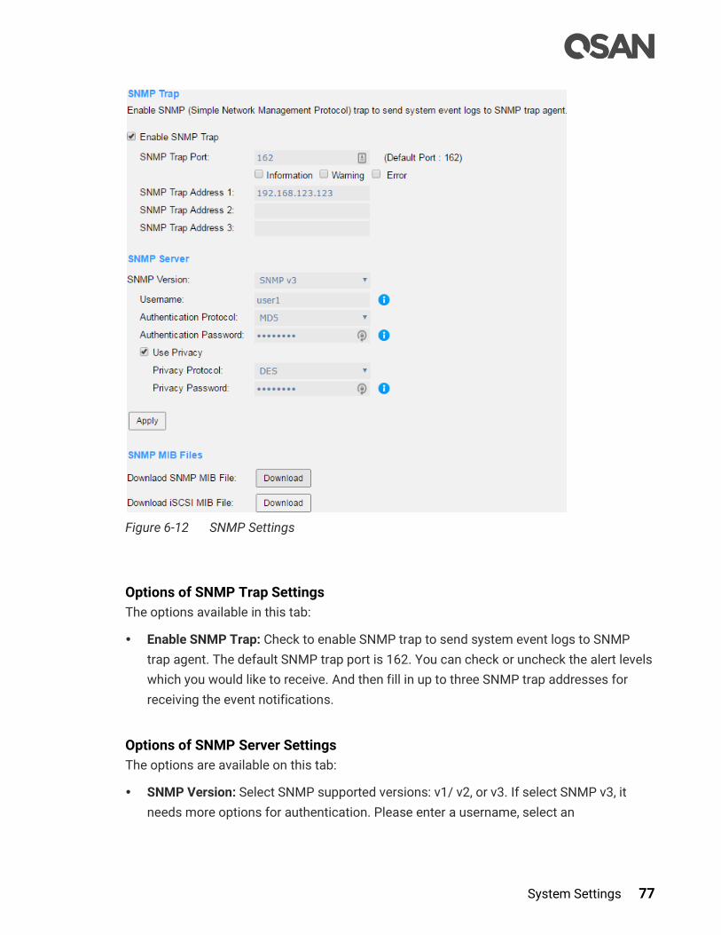
System Settings 77
Figure 6-12 SNMP Settings
Options of SNMP Trap Settings
The options available in this tab:
Enable SNMP Trap: Check to enable SNMP trap to send system event logs to SNMP
trap agent. The default SNMP trap port is 162. You can check or uncheck the alert levels
which you would like to receive. And then fill in up to three SNMP trap addresses for
receiving the event notifications.
Options of SNMP Server Settings
The options are available on this tab:
SNMP Version: Select SNMP supported versions: v1/ v2, or v3. If select SNMP v3, it
needs more options for authentication. Please enter a username, select an
78 © Copyright 2018 QSAN Technology, Inc. All Right Reserved.
authentication protocol and enter an authentication password, check to use privacy if
necessary, select a privacy protocol, and enter a privacy password.
When finished, click the Apply button to take effect.
INFORMATION:
Authentication Protocol:
MD5: The MD5 algorithm is a widely used hash function producing a
128-bit hash value. It can still be used as a checksum to verify data
integrity, but only against unintentional corruption.
SHA: SHA (Secure Hash Algorithm) is a cryptographic hash function
which is a mathematical operation run on digital data; by comparing
the computed "hash" (the output from execution of the algorithm) to a
known and expected hash value, a person can determine the data's
integrity.
Privacy Protocol:
DES: The DES (Data Encryption Standard) is a symmetric-key
algorithm for the encryption of electronic data.
AES: The AES (Advanced Encryption Standard) is a specification for
the encryption of electronic data. It supersedes the DES.
Options of SNMP MIB Files
The options available in this tab:
Download SNMP MIB File: Click Download button to save the SNMP MIB file which can
be imported to the SNMP client tool to get system information. You can view fan,
voltage, and system status via SNMP MIB.
Download iSCSI MIB File: Click Download button to save the iSCSI MIB file which can be
imported to the SNMP client tool to get network information. You can view iSCSI traffic
via iSCSI MIB.
6.5. Maintenance
The Maintenance function submenu provides System Information, Upgrade, Firmware
Synchronization (This option is only visible when dual controllers is installed.), System
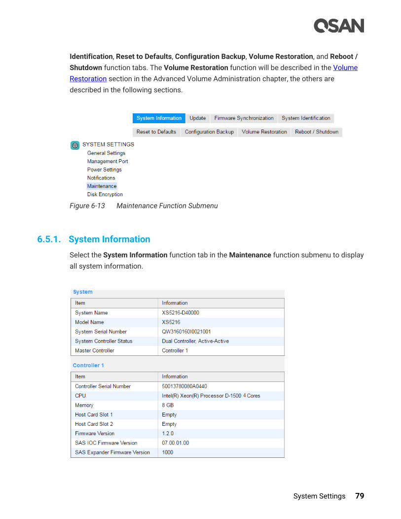
System Settings 79
Identification, Reset to Defaults, Configuration Backup, Volume Restoration, and Reboot /
Shutdown function tabs. The Volume Restoration function will be described in the Volume
Restoration section in the Advanced Volume Administration chapter, the others are
described in the following sections.
Figure 6-13 Maintenance Function Submenu
6.5.1. System Information
Select the System Information function tab in the Maintenance function submenu to display
all system information.

80 © Copyright 2018 QSAN Technology, Inc. All Right Reserved.
Figure 6-14 System Information
This table shows the descriptions.
Table 6-4 Status in System Information Column Descriptions
Column Name Description
System
Availability
Status
The status of system availability:
Dual Controller, Active/Active: Dual controllers and expansion
units are in normal stage.
Dual Controller, Degraded: In dual controller mode, one controller
or one of expansion unit fails, or they have been plugged out.
Please replace or insert a good controller.
Dual Controller, Lockdown: In dual controller mode, the
configurations of two controllers are different, including the
memory capacity, host cards, and controller firmware version.
Please check the hardware configurations of two controllers or
execute firmware synchronization.
Single Controller: Single controller mode.
System Settings 81
Options of System Information
The options available in this tab:
Download Service Package: Click button to download system information for service.
CAUTION:
If you try to increase the system memory and running in dual controller
mode, please make sure both controllers have the same DIMM on each
corresponding memory slot. Failing to do so will result in controller
malfunction, which will not be covered by warranty.
6.5.2. Firmware Update
Select the Update function tab in the Maintenance function submenu to be used to update
controller firmware, expansion unit firmware, change operation mode, and active licenses.
TIP:
Before upgrading, we recommend you to export your system
configurations first in the Configuration Backup function tab. Please refer
to the Configuration Backup section for more details.
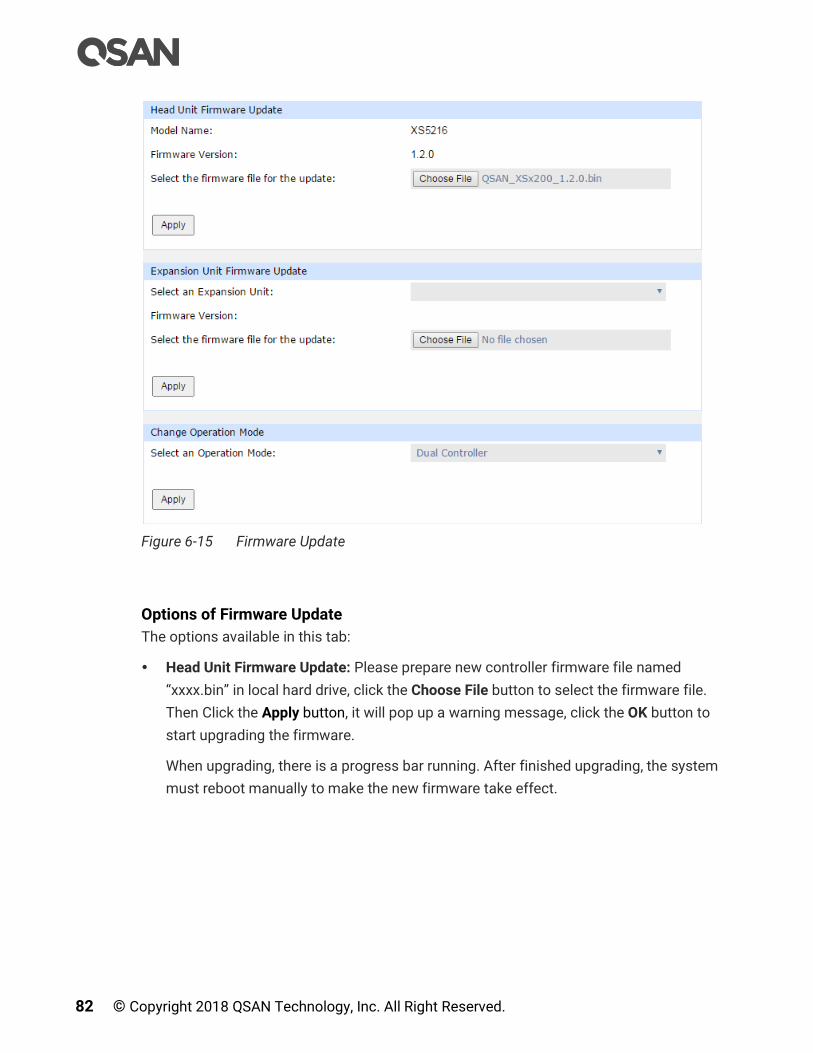
82 © Copyright 2018 QSAN Technology, Inc. All Right Reserved.
Figure 6-15 Firmware Update
Options of Firmware Update
The options available in this tab:
Head Unit Firmware Update: Please prepare new controller firmware file named
“xxxx.bin” in local hard drive, click the Choose File button to select the firmware file.
Then Click the Apply button, it will pop up a warning message, click the OK button to
start upgrading the firmware.
When upgrading, there is a progress bar running. After finished upgrading, the system
must reboot manually to make the new firmware take effect.

System Settings 83
TIP:
Firmware update can be done without downtime if the MPIO configuration
is well-configured between the connected host / server and both
controllers. A firmware update process will update both controllers at the
same time. After finished updating, you have to reboot the system.
A system reboot will reboot the master controller first. At this point, the
slave controller will take over all tasks (and becomes a new master
controller). After the original master controller finishes the booting
process (the original master controller is slave controller at this moment),
the new master controller (the original slave controller) will reboot
automatically, and so on for the original master controller to take over the
tasks, once the original slave controller finishes the booting process, the
firmware update procedure is completed.
Expansion Unit Firmware Update: To upgrade expansion unit firmware, first select an
expansion unit. Then other steps are the same as the head unit firmware update. After
finished upgrading, the expansion unit must reboot manually to make the new firmware
take effect.
Change the Operation Mode: This option can be modified to operate in dual-controller or
single-controller mode here. If the system installed only one controller, switch this mode
to Single Controller, and then click the Apply button. After changing the operation mode,
the system must reboot manually to take effect.
Figure 6-16 Enable Licenses

84 © Copyright 2018 QSAN Technology, Inc. All Right Reserved.
SSD Cache License: This option enables SSD cache. Download Request License file and
send to your local sales to obtain a License Key. After getting the license key, click
Choose File button to select it, and then click the Apply button to enable. Each license
key is unique and dedicated to a specific system. If you have already enabled, this
option will be invisible. After enabling the license, the system must reboot manually to
take effect.
Auto Tiering License: This option enables auto tiering. The operation is the same as
SSD cache.
TIP:
After enabling the licenses, the functions cannot be disabled and these
license options will be hidden.
6.5.3. Firmware Synchronization
Select the Firmware Synchronization function tab in the Maintenance function submenu to
be used on dual controller systems to synchronize the controller firmware versions when
the firmware of the master controller and the slave controller are different. The firmware of
slave controller is always changed to match the firmware of the master controller. It doesn’t
matter if the firmware version of slave controller is newer or older than that of the master.
Normally, the firmware versions in both controllers are the same.
Figure 6-17 Both Firmware Versions are Synchronized
If the firmware versions between two controllers are different, it will display the warning
message. Click the Apply button to synchronize and force a reboot.
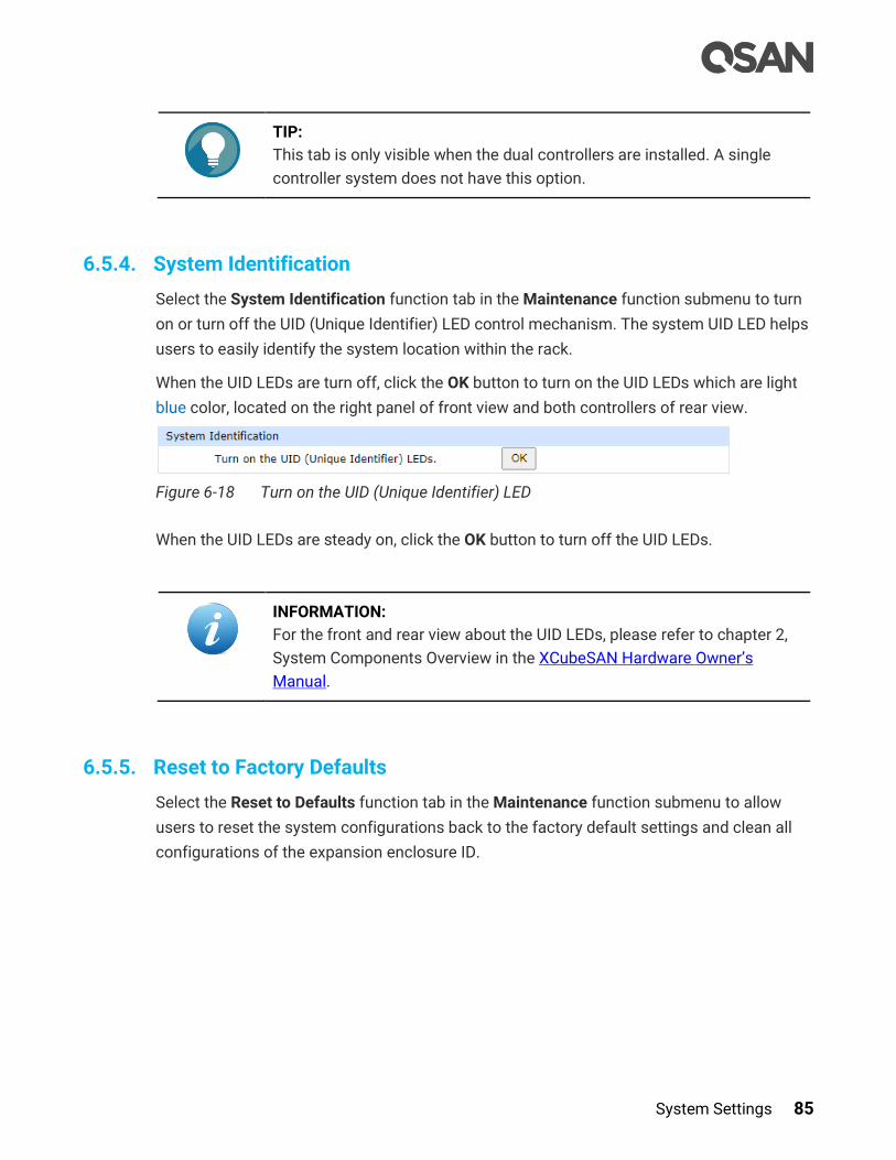
System Settings 85
TIP:
This tab is only visible when the dual controllers are installed. A single
controller system does not have this option.
6.5.4. System Identification
Select the System Identification function tab in the Maintenance function submenu to turn
on or turn off the UID (Unique Identifier) LED control mechanism. The system UID LED helps
users to easily identify the system location within the rack.
When the UID LEDs are turn off, click the OK button to turn on the UID LEDs which are light
blue color, located on the right panel of front view and both controllers of rear view.
Figure 6-18 Turn on the UID (Unique Identifier) LED
When the UID LEDs are steady on, click the OK button to turn off the UID LEDs.
INFORMATION:
For the front and rear view about the UID LEDs, please refer to chapter 2,
System Components Overview in the XCubeSAN Hardware Owner’s
Manual.
6.5.5. Reset to Factory Defaults
Select the Reset to Defaults function tab in the Maintenance function submenu to allow
users to reset the system configurations back to the factory default settings and clean all
configurations of the expansion enclosure ID.

86 © Copyright 2018 QSAN Technology, Inc. All Right Reserved.
Figure 6-19 Reset to Defaults
Options of Resets to Factory Defaults
The options available in this tab:
Reset to Defaults: Click the Reset button to progress reset to defaults and force a
reboot. The default settings are:
。 Reset Management Port IP address to DHCP, and then fix IP address:
169.254.1.234/16.
。 Reset admin’s Password to 1234.
。 Reset System Name to model name plus the last 6 digits of serial number. For
example: XS5216-123456.
。 Reset IP addresses of all iSCSI Ports to 192.168.1.1, 192.168.2.1, … etc.
。 Reset link speed of all Fibre Channel Ports to Automatic.
。 Clear all access control settings of the host connectivity.
Clear all volume restoration records: Check to clear all volume restoration records.
CAUTION:
Process the Reset to Defaults function will force a reboot. To clear all
volume restoration records is irreversible. The system won't be able to
restore the recorded RAID configuration if it fails while there is no record.
Please carefully consider before making this reset.
System Settings 87
Clean Expansion Enclosure ID: Click the Clean button to clean all configurations of
expansion enclosure ID. A clean will cause the system shutdown, and then you have to
start manually.
INFORMATION:
The XCubeDAS XD5300 series features the seven-segment LED display
for users to easily identify a specific XCubeDAS system. The enclosure ID
is assigned by head unit (XCubeSAN series) automatically. The seven -
segment LED display supports up to ten XCubeDAS systems, and the
numbering rule will start from 1 to A. For dual controller models, both
controllers will display the same enclosure ID. After the XD5300 had been
assigned the enclosure ID, head unit will assign the same enclosure ID
when the system reboots or goes shutdown. For hardware information
enclosure ID, please refer to the chapter 2.7, Seven-segment LED Display
section in the XCubeDAS Hardware Owner’s Manual.
CAUTION:
Process the Clean Expansion Enclosure ID function will force the system
shutdown to clean all configurations of expansion enclosure ID.
6.5.6. Configuration Backup
Select the Configuration Backup function tab in the Maintenance function submenu to be
used to either save system configuration (export) or apply a saved configuration (import).

88 © Copyright 2018 QSAN Technology, Inc. All Right Reserved.
Figure 6-20 Configuration Backup
While the volume configuration settings are available for exporting, to prevent conflicts and
overwriting existing data, they cannot be imported.
Options of Configuration Backup
The options available in this tab:
Import: Import all system configurations excluding volume configuration.
Export: Export all configurations to a file.
CAUTION:
The Import option will import all system configurations excluding volume
configuration. The current system configurations will be replaced.
6.5.7. Reboot and Shutdown
Select the Reboot / Shutdown tab in the Maintenance function submenu to be used to
reboot or shutdown the system. Before powering off the system, it is highly recommended
to execute Shutdown function to flush all data from memory cache into the disk drives. The
step is important for data protection.

System Settings 89
Figure 6-21 Reboot and Shutdown
The Reboot function has three options; reboot both controllers, controller 1 only or
controller 2 only.
Figure 6-22 Reboot Options
6.6. Disk Encryption
The Disk Encryption function submenu provides Authentication, and SEDs function tabs.
SED (Self-Encrypting Drive) support will be described in the chapter 14, SED and ISE Support
chapter.
Figure 6-23 Disk Encryption Function Submenu

90 © Copyright 2018 QSAN Technology, Inc. All Right Reserved.
7. Host Configuration
This chapter describes host protocol concepts and the details of host configuration. The
HOST CONFIGURATION function menu provides submenus of Overview, iSCSI Ports, and
Fibre Channel Ports.
TIP:
The Fibre Channel Ports function menu will appear only when the system
has a fibre channel host card installed.
7.1. Host Protocol Technology
This section describes the host protocol technology of iSCSI (Internet SCSI) and fibre
channel.
7.1.1. iSCSI Technology
iSCSI (Internet SCSI) is a protocol which encapsulates SCSI (Small Computer System
Interface) commands and data in TCP/IP packets for linking storage devices with servers
over common IP infrastructures. iSCSI provides high performance SANs over standard IP
networks like LAN, WAN or the Internet.
IP SANs are true SANs (Storage Area Networks) which allow several servers to attach to an
infinite number of storage volumes by using iSCSI over TCP/IP networks. IP SANs can scale
the storage capacity with any type and brand of storage system. In addition, it can be used
by any type of network (Ethernet, Fast Ethernet, Gigabit Ethernet, and 10 Gigabit Ethernet)
and combination of operating systems (Microsoft Windows, Linux, Solaris, Mac, etc.) within
the SAN network. IP-SANs also include mechanisms for security, data replication, multi-path
and high availability.
Storage protocols, such as iSCSI, have “two ends” in the connection. These ends are initiator
and target. In iSCSI, we call them iSCSI initiator and iSCSI target. The iSCSI initiator requests
or initiates any iSCSI communication. It requests all SCSI operations like read or write. An
initiator is usually located on the host side (either an iSCSI HBA or iSCSI SW initiator).
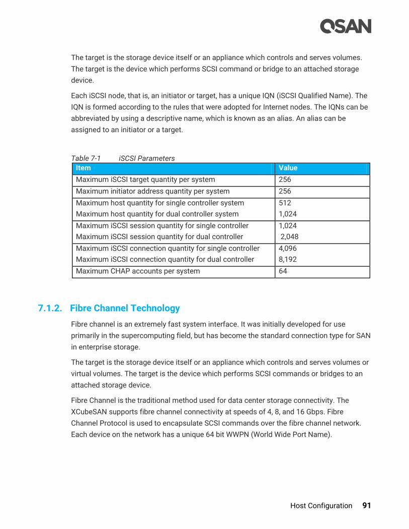
Host Configuration 91
The target is the storage device itself or an appliance which controls and serves volumes.
The target is the device which performs SCSI command or bridge to an attached storage
device.
Each iSCSI node, that is, an initiator or target, has a unique IQN (iSCSI Qualified Name). The
IQN is formed according to the rules that were adopted for Internet nodes. The IQNs can be
abbreviated by using a descriptive name, which is known as an alias. An alias can be
assigned to an initiator or a target.
Table 7-1 iSCSI Parameters
Item Value
Maximum iSCSI target quantity per system 256
Maximum initiator address quantity per system 256
Maximum host quantity for single controller system
Maximum host quantity for dual controller system
512
1,024
Maximum iSCSI session quantity for single controller
Maximum iSCSI session quantity for dual controller
1,024
2,048
Maximum iSCSI connection quantity for single controller
Maximum iSCSI connection quantity for dual controller
4,096
8,192
Maximum CHAP accounts per system 64
7.1.2. Fibre Channel Technology
Fibre channel is an extremely fast system interface. It was initially developed for use
primarily in the supercomputing field, but has become the standard connection type for SAN
in enterprise storage.
The target is the storage device itself or an appliance which controls and serves volumes or
virtual volumes. The target is the device which performs SCSI commands or bridges to an
attached storage device.
Fibre Channel is the traditional method used for data center storage connectivity. The
XCubeSAN supports fibre channel connectivity at speeds of 4, 8, and 16 Gbps. Fibre
Channel Protocol is used to encapsulate SCSI commands over the fibre channel network.
Each device on the network has a unique 64 bit WWPN (World Wide Port Name).
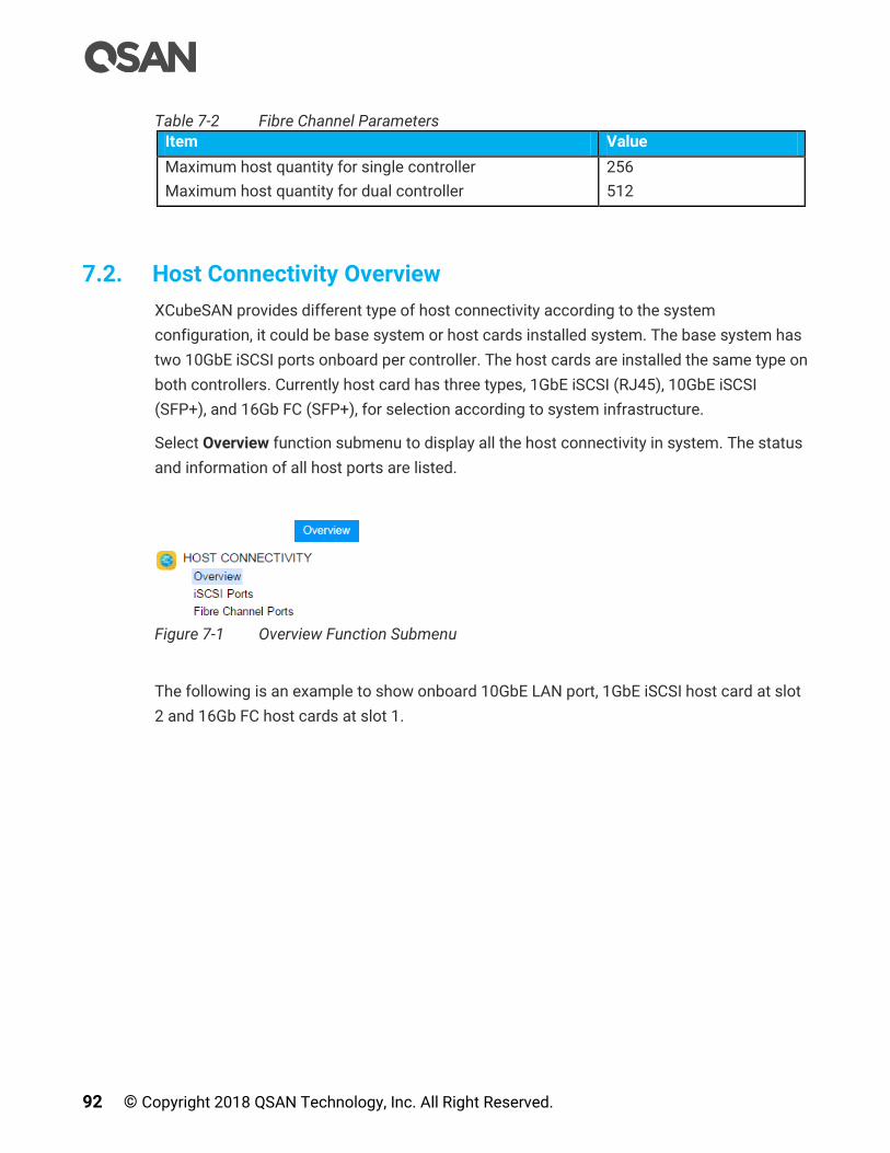
92 © Copyright 2018 QSAN Technology, Inc. All Right Reserved.
Table 7-2 Fibre Channel Parameters
Item Value
Maximum host quantity for single controller
Maximum host quantity for dual controller
256
512
7.2. Host Connectivity Overview
XCubeSAN provides different type of host connectivity according to the system
configuration, it could be base system or host cards installed system. The base system has
two 10GbE iSCSI ports onboard per controller. The host cards are installed the same type on
both controllers. Currently host card has three types, 1GbE iSCSI (RJ45), 10GbE iSCSI
(SFP+), and 16Gb FC (SFP+), for selection according to system infrastructure.
Select Overview function submenu to display all the host connectivity in system. The status
and information of all host ports are listed.
Figure 7-1 Overview Function Submenu
The following is an example to show onboard 10GbE LAN port, 1GbE iSCSI host card at slot
2 and 16Gb FC host cards at slot 1.
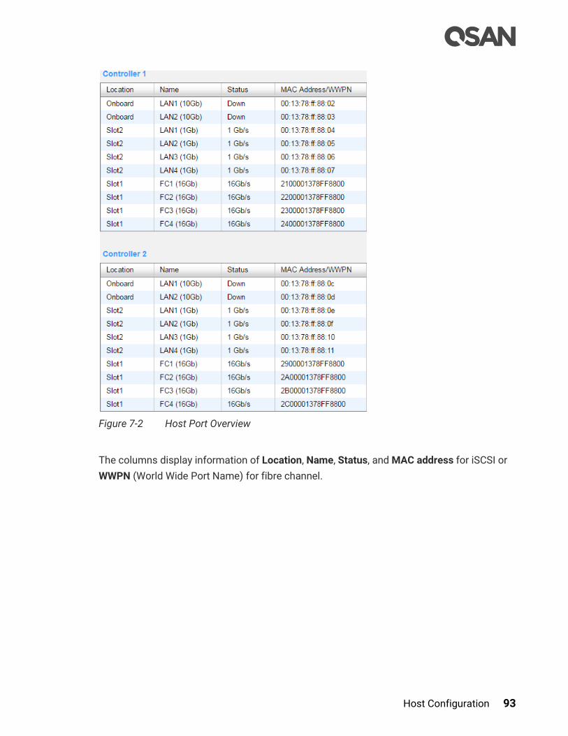
Host Configuration 93
Figure 7-2 Host Port Overview
The columns display information of Location, Name, Status, and MAC address for iSCSI or
WWPN (World Wide Port Name) for fibre channel.

94 © Copyright 2018 QSAN Technology, Inc. All Right Reserved.
INFORMATION:
Fibre Channel / iSCSI Host Card at Slot 1:
HQ-16F4S2: 4 x 16Gb FC (SFP+) ports
HQ-16F2S2: 2 x 16Gb FC (SFP+) ports
HQ-10G4S2: 4 x 10GbE iSCSI (SFP+) ports
HQ-10G2T: 2 x 10GBASE-T iSCSI (RJ45) ports
HQ-01G4T: 4 x 1GBASE-T iSCSI (RJ45) ports
iSCSI Host Card at Slot 2 (20Gb bandwidth):
HQ-16F2S2: 2 x 16Gb FC (SFP+) ports
HQ-10G4S2, 4 x 10GbE iSCSI (SFP+) ports
HQ-10G2T: 2 x 10GBASE-T iSCSI (RJ45) ports
HQ-01G4T, 4 x 1GBASE-T iSCSI (RJ45) ports
INFORMATION:
For hardware information about host cards, please refer to the chapter
3.3, Installing the Optional Host Cards section in the XCubeSAN Hardware
Owner’s Manual.
CAUTION:
If you change the configuration of the host cards including insert or
remove them, it has to execute Reset to Defaults function in SYSTEM
SETTINGS -> Maintenance -> Reset to Defaults. Before that, you can keep
the system configurations by export and import the configuration file in
SYSTEM SETTINGS -> Maintenance -> Configuration Backup. Please
refer to the chapter 6.5.5, Reset to Factory Default section and the chapter
6.5.5, Configuration Backup section for more details.
7.3. Configure iSCSI Connectivity
The iSCSI Ports provides iSCSI Ports, iSCSI Settings, iSCSI Targets, CHAP Accounts, and
Sessions function tabs to configure iSCSI ports.
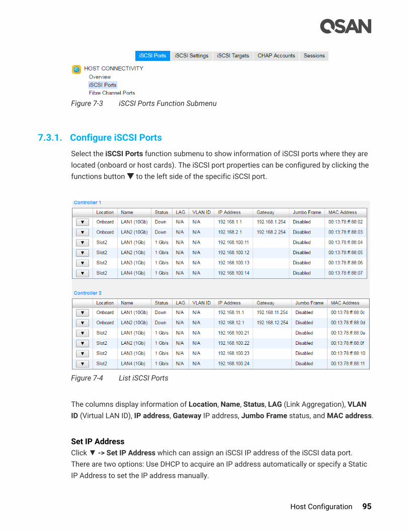
Host Configuration 95
Figure 7-3 iSCSI Ports Function Submenu
7.3.1. Configure iSCSI Ports
Select the iSCSI Ports function submenu to show information of iSCSI ports where they are
located (onboard or host cards). The iSCSI port properties can be configured by clicking the
functions button to the left side of the specific iSCSI port.
Figure 7-4 List iSCSI Ports
The columns display information of Location, Name, Status, LAG (Link Aggregation), VLAN
ID (Virtual LAN ID), IP address, Gateway IP address, Jumbo Frame status, and MAC address.
Set IP Address
Click ▼ -> Set IP Address which can assign an iSCSI IP address of the iSCSI data port.
There are two options: Use DHCP to acquire an IP address automatically or specify a Static
IP Address to set the IP address manually.
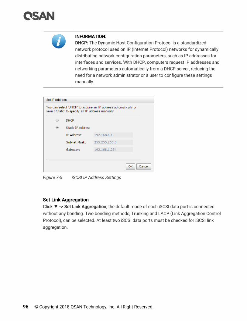
96 © Copyright 2018 QSAN Technology, Inc. All Right Reserved.
INFORMATION:
DHCP: The Dynamic Host Configuration Protocol is a standardized
network protocol used on IP (Internet Protocol) networks for dynamically
distributing network configuration parameters, such as IP addresses for
interfaces and services. With DHCP, computers request IP addresses and
networking parameters automatically from a DHCP server, reducing the
need for a network administrator or a user to configure these settings
manually.
Figure 7-5 iSCSI IP Address Settings
Set Link Aggregation
Click ▼ -> Set Link Aggregation, the default mode of each iSCSI data port is connected
without any bonding. Two bonding methods, Trunking and LACP (Link Aggregation Control
Protocol), can be selected. At least two iSCSI data ports must be checked for iSCSI link
aggregation.

Host Configuration 97
Figure 7-6 Set Link Aggregation
INFORMATION:
Trunking: Sometimes called “Port Trunking” configures multiple iSCSI
ports to be grouped together into one in order to increase the connection
speed beyond the limit of a single iSCSI port.
LACP: The Link Aggregation Control Protocol is part of IEEE 802.3ad that
allows bonding several physical ports together to form a single logical
channel. LACP allows a network switch to negotiate an automatic bundle
by sending LACP packets to the peer. LACP can increase bandwidth
usage and automatically perform failover when the link status fails on a
port.
Set VLAN ID
Click ▼ -> Set VLAN ID, VLAN (Virtual LAN) is a logical grouping mechanism implemented
on switch device. VLANs are collections of switching ports that comprise a single broadcast
domain. It allows network traffic to transfer more efficiently within these logical subgroups.
Please consult your network switch user manual for VLAN setting instructions. Most of the
work is done at the switch. Please make sure that your VLAN ID of iSCSI port matches that
of switch port. If your network environment supports VLAN, you can use this function to
change the configurations. Fill in VLAN ID and Priority settings to enable VLAN.

98 © Copyright 2018 QSAN Technology, Inc. All Right Reserved.
Figure 7-7 Set VLAN ID
INFORMATION:
VLAN ID: VLAN ID is a number ranges from 2 to 4094. Three numbers (0,
1, and 4095) are reserved for special purposes.
Priority: The PCP (Priority Code Point) is a number ranges from 0 to 7 and
reserved for QoS (Quality of Service). The definition is compliant with IEEE
802.1p protocol and 0 is the default value. In normal cases, you don't need
to set this value.
Set Default Gateway
Click ▼ -> Set Default Gateway to set the gateway of the IP address as default gateway.
There can be only one default gateway.
Remove Default Gateway
To remove the default gateway, click ▼ -> Remove Default Gateway.
Set Jumbo Frames
Click ▼ -> Set Jumbo Frames to set the MTU (Maximum Transmission Unit) size. The
jumbo frame size could be set as 4000 or 9000 bytes. Jumbo Frame is disabled by default.
Figure 7-8 Set Jumbo Frame

Host Configuration 99
CAUTION:
If the VLAN ID or jumbo frames are set, the related switching hub and
HBA on host must be set, too. Otherwise, the LAN connection cannot
work properly.
Ping Host
Click ▼ -> Ping Host, it can verify the port connection from a target to the corresponding
host data port. Input the host’s IP address and click Start button. The system will display the
ping result. Click Stop button will stop ping activity.
Figure 7-9 Ping Host
Reset Port
Click -> Reset Port, which is generally used to recover from a port malfunction.
7.3.2. Configure iSCSI Settings
Select the iSCSI Settings function tab in the iSCSI Ports function submenu to provide to
setup entity name of the system and iSNS (Internet Storage Name Service) server. The
entity name is default in IQN (iSCSI Qualified Name) format and could be modified for
management purpose. The iSNS IP is used by iSNS protocol for automated discovery,
management and configuration of iSCSI devices on a TCP/IP network. To use iSNS, an iSNS
server must be added to the SAN. The iSNS server IP address must be added to the storage
system for iSCSI initiator service to send queries.

100 © Copyright 2018 QSAN Technology, Inc. All Right Reserved.
Figure 7-10 Entity Name and iSNS Settings
Options of iSCSI Settings
The options available in this tab:
Entity Name: Change the entity name; highlight the old name and type in a new one. The
maximum length of entity name is 200 characters. Valid characters are [ a~z | 0~9 | -.: ].
iSNS IP Address: The option can change iSNS IP address for internet storage name
service.
When finished, click the Apply button to effect changes.
INFORMATION:
iSNS: The iSNS protocol allows automated discovery, management, and
configuration of iSCSI devices on a network.
7.3.3. Configure iSCSI Targets
Select the iSCSI Targets function tab in the iSCSI Ports function submenu to show the iSCSI
target information for iSCSI initiator. The iSCSI target properties can be configured by
clicking the functions button to the left side of the specific iSCSI target.

Host Configuration 101
Figure 7-11 iSCSI Targets
Change Authentication Mode
Click ▼ -> Authentication Method to enable CHAP (Challenge Handshake Authentication
Protocol) and mutual CHAP authentication method used in point-to-point for user login.
CHAP is a type of authentication in which the authentication server sends the client a key to
be used for encrypting the username and password. It enables the username and password
to transmit in an encrypted form for protection.
In addition, mutual CHAP is a two-way authentication between the iSCSI target and the
initiator. User has to enter another username and password which are set in the initiator
side.
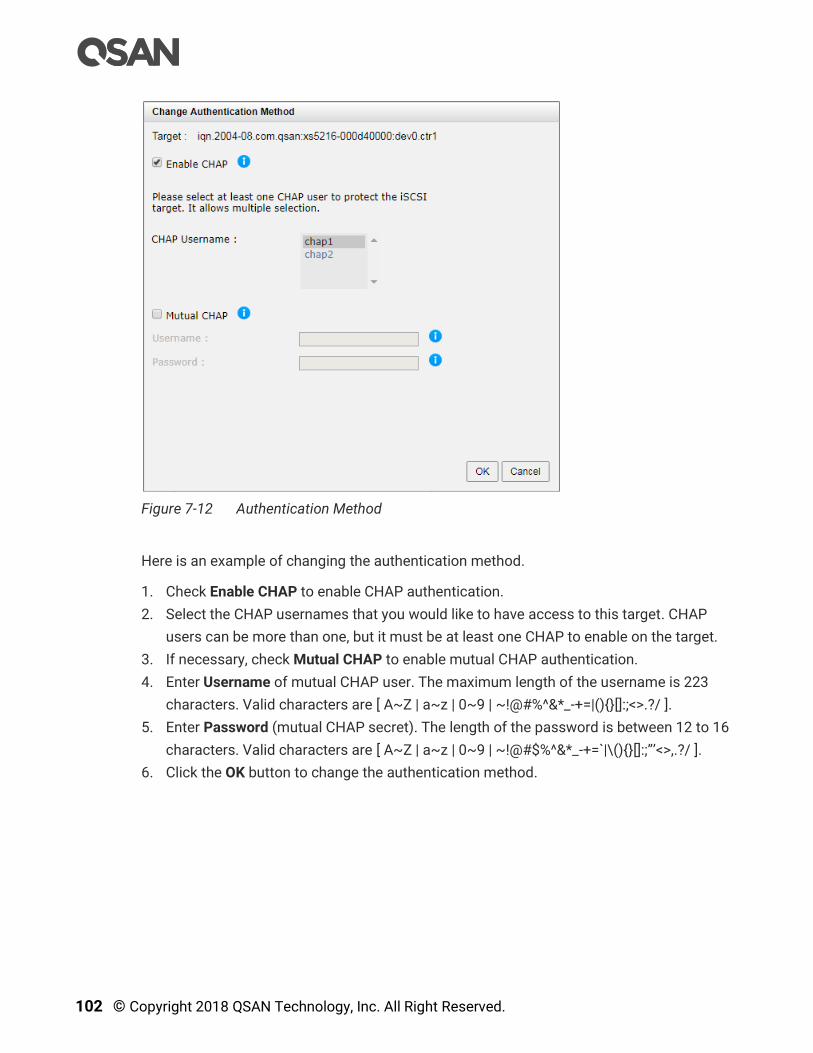
102 © Copyright 2018 QSAN Technology, Inc. All Right Reserved.
Figure 7-12 Authentication Method
Here is an example of changing the authentication method.
1. Check Enable CHAP to enable CHAP authentication.
2. Select the CHAP usernames that you would like to have access to this target. CHAP
users can be more than one, but it must be at least one CHAP to enable on the target.
3. If necessary, check Mutual CHAP to enable mutual CHAP authentication.
4. Enter Username of mutual CHAP user. The maximum length of the username is 223
characters. Valid characters are [ A~Z | a~z | 0~9 | ~!@#%^&*_-+=|(){}[]:;<>.?/ ].
5. Enter Password (mutual CHAP secret). The length of the password is between 12 to 16
characters. Valid characters are [ A~Z | a~z | 0~9 | ~!@#$%^&*_-+=`|\(){}[]:;”’<>,.?/ ].
6. Click the OK button to change the authentication method.
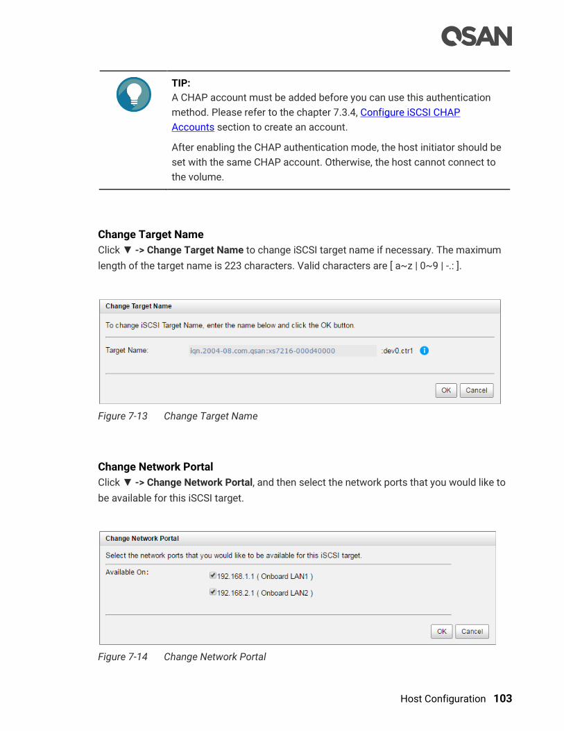
Host Configuration 103
TIP:
A CHAP account must be added before you can use this authentication
method. Please refer to the chapter 7.3.4, Configure iSCSI CHAP
Accounts section to create an account.
After enabling the CHAP authentication mode, the host initiator should be
set with the same CHAP account. Otherwise, the host cannot connect to
the volume.
Change Target Name
Click ▼ -> Change Target Name to change iSCSI target name if necessary. The maximum
length of the target name is 223 characters. Valid characters are [ a~z | 0~9 | -.: ].
Figure 7-13 Change Target Name
Change Network Portal
Click ▼ -> Change Network Portal, and then select the network ports that you would like to
be available for this iSCSI target.
Figure 7-14 Change Network Portal
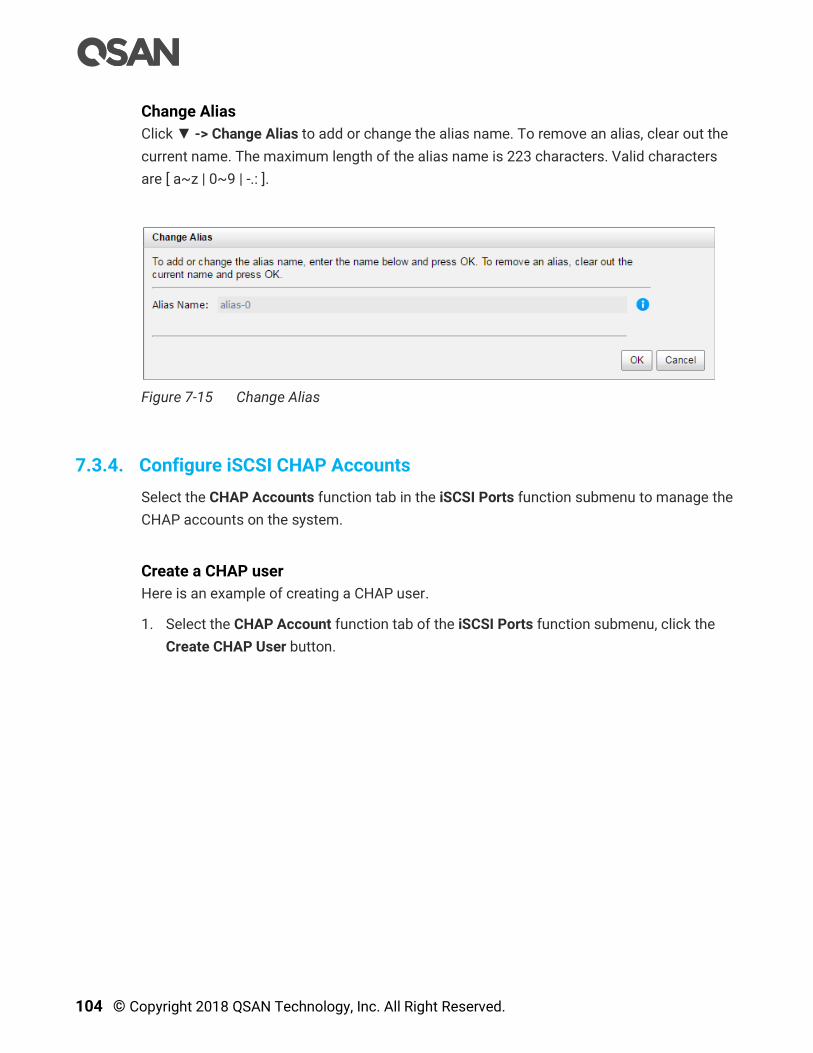
104 © Copyright 2018 QSAN Technology, Inc. All Right Reserved.
Change Alias
Click ▼ -> Change Alias to add or change the alias name. To remove an alias, clear out the
current name. The maximum length of the alias name is 223 characters. Valid characters
are [ a~z | 0~9 | -.: ].
Figure 7-15 Change Alias
7.3.4. Configure iSCSI CHAP Accounts
Select the CHAP Accounts function tab in the iSCSI Ports function submenu to manage the
CHAP accounts on the system.
Create a CHAP user
Here is an example of creating a CHAP user.
1. Select the CHAP Account function tab of the iSCSI Ports function submenu, click the
Create CHAP User button.
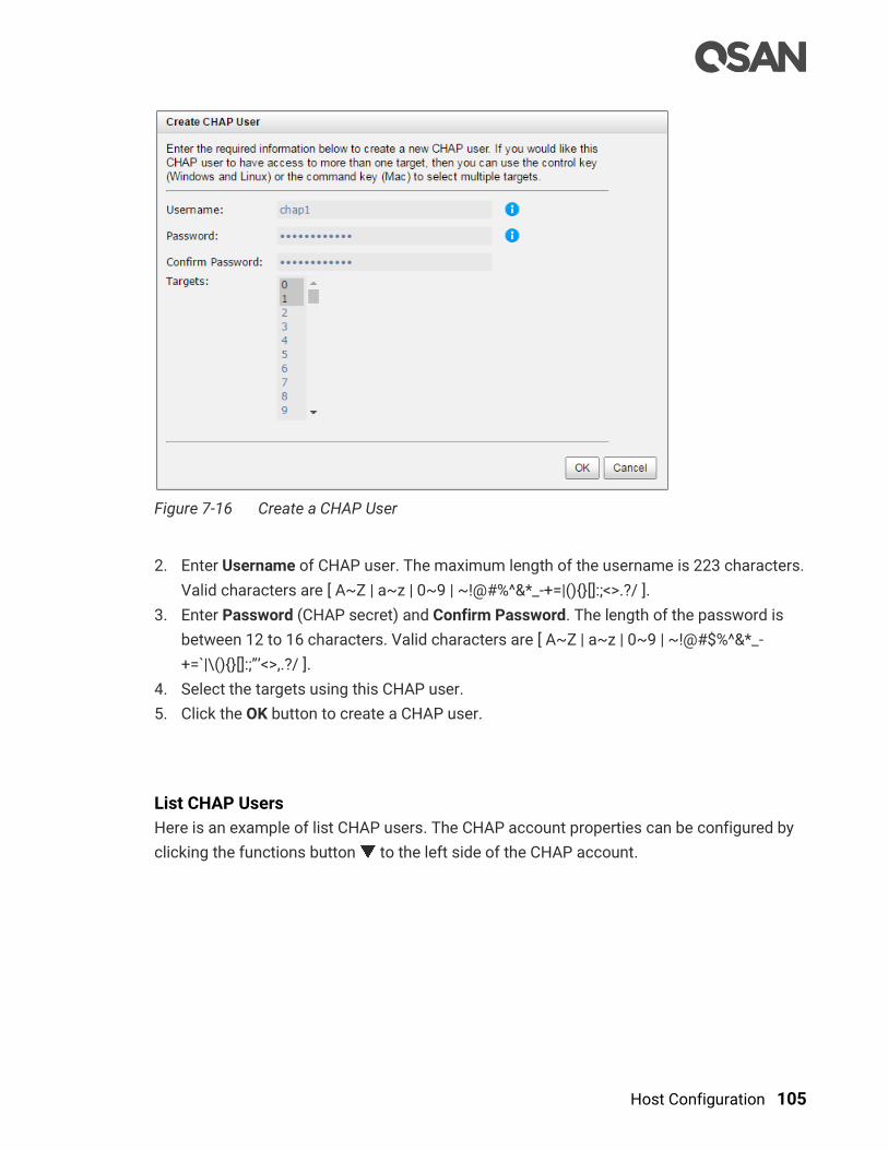
Host Configuration 105
Figure 7-16 Create a CHAP User
2. Enter Username of CHAP user. The maximum length of the username is 223 characters.
Valid characters are [ A~Z | a~z | 0~9 | ~!@#%^&*_-+=|(){}[]:;<>.?/ ].
3. Enter Password (CHAP secret) and Confirm Password. The length of the password is
between 12 to 16 characters. Valid characters are [ A~Z | a~z | 0~9 | ~!@#$%^&*_-
+=`|\(){}[]:;”’<>,.?/ ].
4. Select the targets using this CHAP user.
5. Click the OK button to create a CHAP user.
List CHAP Users
Here is an example of list CHAP users. The CHAP account properties can be configured by
clicking the functions button to the left side of the CHAP account.

106 © Copyright 2018 QSAN Technology, Inc. All Right Reserved.
Figure 7-17 List CHAP Users
Modify CHAP User
Click ▼ -> Modify CHAP User to modify the selected CHAP user information. To change the
targets that this user has access to, please go to iSCSI Targets tab, click on the option
menu, and select Change CHAP Users. For more information, please refer to the chapter
7.3.3, Configure for iSCSI Targets section.
Figure 7-18 Modify a CHAP User
Here is an example of modifying the CHAP user.
6. Enter Username of CHAP user. The maximum length of the username is 223 characters.
Valid characters are [ A~Z | a~z | 0~9 | ~!@#%^&*_-+=|(){}[]:;<>.?/ ].
7. Enter Password (CHAP secret) and Confirm Password. The length of the password is
between 12 to 16 characters. Valid characters are [ A~Z | a~z | 0~9 | ~!@#$%^&*_-
+=`|\(){}[]:;”’<>,.?/ ].
8. Click the OK button to modify the CHAP user.
Delete CHAP User
Click ▼ -> Delete CHAP User to delete the selected CHAP user.
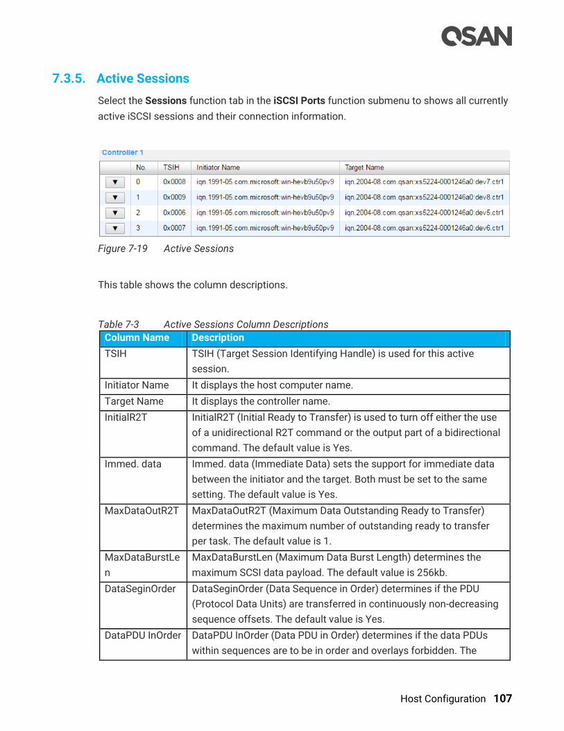
Host Configuration 107
7.3.5. Active Sessions
Select the Sessions function tab in the iSCSI Ports function submenu to shows all currently
active iSCSI sessions and their connection information.
Figure 7-19 Active Sessions
This table shows the column descriptions.
Table 7-3 Active Sessions Column Descriptions
Column Name Description
TSIH TSIH (Target Session Identifying Handle) is used for this active
session.
Initiator Name It displays the host computer name.
Target Name It displays the controller name.
InitialR2T InitialR2T (Initial Ready to Transfer) is used to turn off either the use
of a unidirectional R2T command or the output part of a bidirectional
command. The default value is Yes.
Immed. data Immed. data (Immediate Data) sets the support for immediate data
between the initiator and the target. Both must be set to the same
setting. The default value is Yes.
MaxDataOutR2T MaxDataOutR2T (Maximum Data Outstanding Ready to Transfer)
determines the maximum number of outstanding ready to transfer
per task. The default value is 1.
MaxDataBurstLe
n
MaxDataBurstLen (Maximum Data Burst Length) determines the
maximum SCSI data payload. The default value is 256kb.
DataSeginOrder DataSeginOrder (Data Sequence in Order) determines if the PDU
(Protocol Data Units) are transferred in continuously non-decreasing
sequence offsets. The default value is Yes.
DataPDU InOrder DataPDU InOrder (Data PDU in Order) determines if the data PDUs
within sequences are to be in order and overlays forbidden. The

108 © Copyright 2018 QSAN Technology, Inc. All Right Reserved.
default value is Yes.
List Connection Details
Click ▼ -> Connection Details which will list all connection(s) of the selected session.
Disconnect Session
Click ▼ -> Disconnect will disconnect the selected session, click the OK button to confirm.
7.4. Configure Fibre Channel Connectivity
Select the Fibre Channel Ports function submenu to show information of installed fibre
channel ports. The fibre channel port properties can be configured by clicking the functions
button to the left side of the specific fibre channel port.
Figure 7-20 Fibre Channel Ports Function Submenu
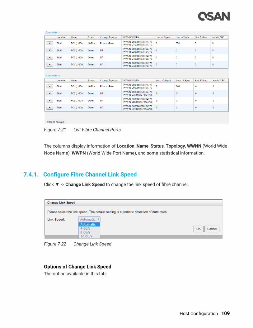
Host Configuration 109
Figure 7-21 List Fibre Channel Ports
The columns display information of Location, Name, Status, Topology, WWNN (World Wide
Node Name), WWPN (World Wide Port Name), and some statistical information.
7.4.1. Configure Fibre Channel Link Speed
Click ▼ -> Change Link Speed to change the link speed of fibre channel.
Figure 7-22 Change Link Speed
Options of Change Link Speed
The option available in this tab:

110 © Copyright 2018 QSAN Technology, Inc. All Right Reserved.
Link Speed: Set the link speed of fibre channel. The options are Automatic (default), 4
Gb/s, 8 Gb/s, and 16 Gb/s. Recommend to set it as Automatic to detect the data rate
automatically.
7.4.2. Configure Fibre Channel Topology
Click ▼ -> Change Topology to change the topology of fibre channel.
Figure 7-23 Change Topology
Options of Change Topology
The option available in this tab:
Topology: Set the topology fibre channel. The option is Point-to-Point for 16 Gb/s fibre
channel, Point-to-Point and Loop modes for 4 Gb/s, 8 Gb/s fibre channel. Set it
appropriately according to your fibre channel environment.
INFORMATION:
Point-to-Point (FC-P2P): Two devices are connected directly by FC
interface. This is the simplest topology with limited connectivity and
supports 4 Gb/s, 8 Gb/s, and 16 Gb/s fibre channel speed.
Loop (FC-AL, Arbitrated Loop): All devices are connection in loop or ring,
similar to token ring networking. Add or remove any device will affect
activities on the loop. The failure of any device will cause ring broken.
Fibre Channel hub connects multiple devices together and may bypass
the failed ports. A loop may also be made by cabling each port to the next
in a ring. Loop mode supports 4 Gb/s and 8 Gb/s fibre channel speed
only.
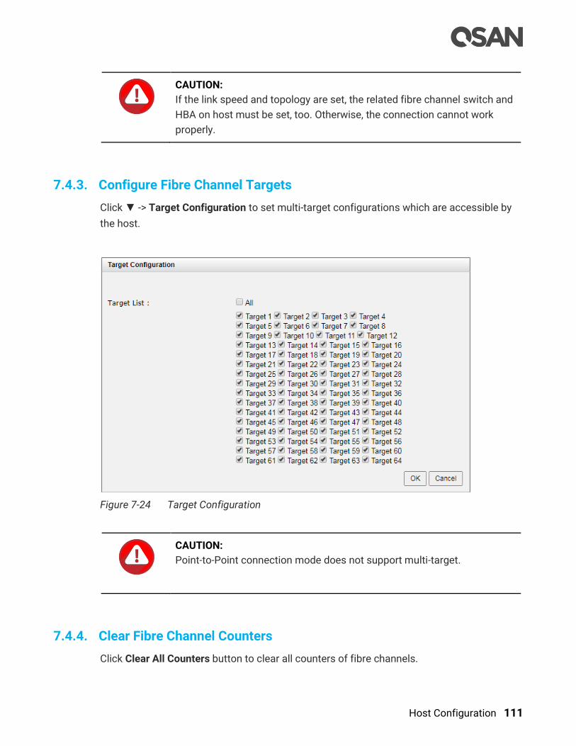
Host Configuration 111
CAUTION:
If the link speed and topology are set, the related fibre channel switch and
HBA on host must be set, too. Otherwise, the connection cannot work
properly.
7.4.3. Configure Fibre Channel Targets
Click ▼ -> Target Configuration to set multi-target configurations which are accessible by
the host.
Figure 7-24 Target Configuration
CAUTION:
Point-to-Point connection mode does not support multi-target.
7.4.4. Clear Fibre Channel Counters
Click Clear All Counters button to clear all counters of fibre channels.

112 © Copyright 2018 QSAN Technology, Inc. All Right Reserved.
Click ▼ -> Clear Counters to clear the counters of the selected fibre channel.

Storage Management 113
8. Storage Management
This chapter describes storage technologies of RAID, storage pool, volume, and LUN
mapping. Also includes the details of storage management operations and examples. The
STORAGE MANAGEMENT function menu provides submenus of Disks, Pools, Volume, and
LUN Mappings. In this chapter, we will focus on the fundamental storage architecture called
thick provisioning. The advanced storage features and functions will be described in the
following.
Thin Provisioning feature is described in the Thin Provisioning chapter.
Auto Tiering feature is described in the Auto Tiering chapter.
SSD Cache feature is described in the SSD Cache chapter.
SED (Self-Encrypting Drive) and ISE (Instant Secure Erase) drive support is described in
the SED and ISE Support chapter.
The data backup functions are described in the following sections.
Snapshot function is described in the Managing Snapshots section.
Local Clone function is described in the Manage Local Clones section.
Remote Replication function is described in the Managing Remote Replications section.
8.1. RAID Technology
RAID is the abbreviation of Redundant Array of Independent Disks. The basic idea of RAID is
to combine multiple drives together to form one large logical drive. This RAID drive obtains
performance, capacity and reliability than a single drive. In point view of the host, the
operating system in host detects the RAID drive as a single storage device.
8.1.1. Traditional RAID Overview
The disk drives in storage are referred to as members of the array. Each array has a RAID
level. RAID levels provide different degrees of redundancy and performance. They also have
different restrictions regarding the quantity of member disk drives in the array. The
following describe the features of RAID levels.

114 © Copyright 2018 QSAN Technology, Inc. All Right Reserved.
RAID 0 (Striping, no redundancy)
RAID 0 consists of striping, without mirroring or parity. It has more than two disks in parallel,
as a large-capacity disk. The capacity of a RAID 0 volume is the sum of the capacities of the
disks. There is no added redundancy for handling disk failures. Thus, failure of one disk
causes the loss of the entire RAID 0 volume. Striping distributes the contents roughly
equally among all member disks, which makes concurrent read or write operations on the
multiple disks and results in performance improvements. The concurrent operations make
the throughput of most read and write operations equal to the throughput of one disk
multiplied by the quantity of disk drives. Increased throughput is the big benefit of RAID 0, at
the cost of increased vulnerability of data due to drive failures.
RAID 1 (Mirroring between two disks)
RAID 1 consists of data mirroring, without parity or striping. Data is written identically to two
drives, thereby producing a mirrored set of drives. Thus, any read request can be serviced by
any member drive. Write throughput is always slower because every drive must be updated,
and the slowest drive limits the write performance. The array continues to operate as long
as at least one drive is functioning.
N-way Mirror (Mirroring between N disks)
It’s an extension of RAID 1. Data is written identically to N drives, thereby producing an N-
way mirrored set of drives
RAID 3 (Striping, can survive one disk drive fault, with parity on a dedicated disk drive)
RAID 3 consists of byte-level striping with dedicated parity. All disk spindle rotation is
synchronized and data is striped such that each sequential byte is on a different drive. Parity
is calculated across corresponding bytes and stored on a dedicated parity drive. The data
disperses on a different hard drive, even if you want to read short information, it may need
all the hard drives to work. So this is more suitable for large amounts of read data requests.
RAID 5 (Striping, can survive one disk drive fault, with interspersed parity over the member disk drives)
RAID 5 consists of block-level striping with distributed parity. It requires at least three disk
drives. Upon failure of a single drive, subsequent reads can be calculated from the
distributed parity such that no data is lost. RAID 5 is seriously affected by the general trends

Storage Management 115
regarding array rebuild time and the chance of disk drive failure during rebuild. Rebuilding an
array requires reading all data from all disks, opening a chance for a second disk drive
failure and the loss of the entire array.
RAID 6 (Striping, can survive two disk drive faults, with interspersed parity over the member disk drives)
RAID 6 consists of block-level striping with double distributed parity. It requires a minimum
of four disks. Double parity provides fault tolerance up to two failed disk drives. This makes
larger RAID groups more practical, especially for high-availability systems, as large-capacity
drives take longer to restore. As with RAID 5, a single drive failure results in reduced
performance of the entire array until the failed drive has been replaced. With a RAID 6 array,
using drives from multiple sources and manufacturers, it is possible to mitigate most of the
problems associated with RAID 5. The larger the drive capacities and the larger the array
size, the more important it becomes to choose RAID 6 instead of RAID 5.
RAID 0+1 (RAID 1 on top of RAID 0)
RAID 0+1 creates a second striped set to mirror a primary striped set. The array continues to
operate with one or more drives failed in the same mirror set, but if drives fail on both sides
of the mirror, the data on the RAID system is lost.
RAID 10 (RAID 0 on top of RAID 1)
RAID 10 creates a striped set from a series of mirrored disk drives. The array can sustain
multiple drive losses so long as no mirror loses all its drives.
RAID 30 (RAID 3 on top of RAID 0)
RAID 30 is the combination of RAID 3 and RAID 0, do RAID 3 first, further RAID 0. It is
composed of multiple sets of RAID 3 stripe access to each other. Because RAID 30 is based
on RAID 3 which requires at least three disk drives, therefore RAID 30 is constituted a
plurality RAID 3, at least six disk drives. RAID 30 can still operate when appearing a
damaged disk drive in disk group of RAID 3. But if any one group of RAID 3 appears two or
two or more disk drives damaged, the entire RAID 30 will fail.
RAID 50 (RAID 5 on top of RAID 0)
RAID 50 is the combination of RAID 5 and RAID 0, do RAID 5 first, further RAID 0. The
concept is the same as RAID 30. RAID 50 requires at least six disk drives. Since RAID 50

116 © Copyright 2018 QSAN Technology, Inc. All Right Reserved.
constitutes stripe of multiple disk group of RAID 5, it has higher performance than RAID 5,
but capacity utilization is lower than RAID 5.
RAID 60 (RAID 6 on top of RAID 0)
RAID 60 is the combination of RAID 6 and RAID 0, do RAID 6 first, further RAID 0. In other
words, it accesses stripes for more than two groups of RAID 6. RAID 6 needs to have at
least four disk drives, so the minimum requirement of RAID 60 is eight disk drives.
RAID 60 can tolerate maximum two damage disk drives in any disk group of RAID 6, while it
still maintains the operating, but as long as it damages three drives in any group of RAID 6,
the entire RAID 60 will fail. Of course, the probability of this case is quite low.
Compared to a simple RAID 6, RAID 60 binds stripes through multiple of RAID 6. Therefore it
has higher performance. However, high threshold usage and the capacity utilization rate are
major problems.
RAID Level Summary
The following is the summary of the RAID levels.
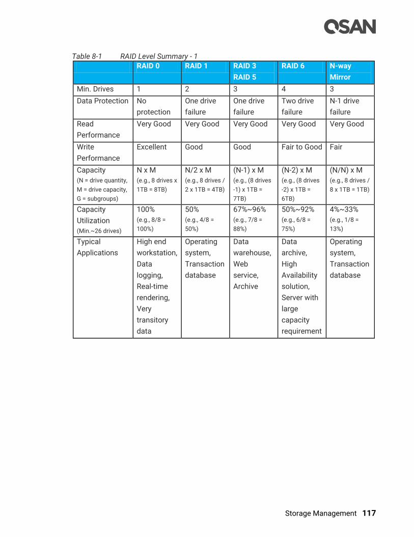
Storage Management 117
Table 8-1 RAID Level Summary - 1
RAID 0 RAID 1 RAID 3
RAID 5
RAID 6 N-way
Mirror
Min. Drives 1 2 3 4 3
Data Protection No
protection
One drive
failure
One drive
failure
Two drive
failure
N-1 drive
failure
Read
Performance
Very Good Very Good Very Good Very Good Very Good
Write
Performance
Excellent Good Good Fair to Good Fair
Capacity
(N = drive quantity,
M = drive capacity,
G = subgroups)
N x M
(e.g., 8 drives x
1TB = 8TB)
N/2 x M
(e.g., 8 drives /
2 x 1TB = 4TB)
(N-1) x M
(e.g., (8 drives
-1) x 1TB =
7TB)
(N-2) x M
(e.g., (8 drives
-2) x 1TB =
6TB)
(N/N) x M
(e.g., 8 drives /
8 x 1TB = 1TB)
Capacity
Utilization
(Min.~26 drives)
100%
(e.g., 8/8 =
100%)
50%
(e.g., 4/8 =
50%)
67%~96%
(e.g., 7/8 =
88%)
50%~92%
(e.g., 6/8 =
75%)
4%~33%
(e.g., 1/8 =
13%)
Typical
Applications
High end
workstation,
Data
logging,
Real-time
rendering,
Very
transitory
data
Operating
system,
Transaction
database
Data
warehouse,
Web
service,
Archive
Data
archive,
High
Availability
solution,
Server with
large
capacity
requirement
Operating
system,
Transaction
database

118 © Copyright 2018 QSAN Technology, Inc. All Right Reserved.
Table 8-2 RAID Level Summary - 2
RAID Level RAID 0+1 RAID 10 RAID 30 RAID 50 RAID 60
Min. Drives 4 4 6 6 8
Data Protection One drive
failure in
each sub-
group
One drive
failure in
each sub-
group
One drive
failure in
each sub-
group
One drive
failure in
each sub-
group
Two drive
failure in
each sub-
group
Read
Performance
Excellent Excellent Very Good Very Good Very Good
Write
Performance
Very Good Very Good Good Good Fair to Good
Capacity
(N = drive quantity,
M = drive capacity,
G = subgroups)
N/2 x M
(e.g., 8 drives /
2 x 1TB = 4TB)
N/2 x M
(e.g., 8 drives /
2 x 1TB = 4TB)
(N-G) x M
(e.g., (8 drives
- 2 subgroups)
x 1TB = 6TB)
(N-G) x M
(e.g., (8 drives
- 2 subgroups)
x 1TB = 6TB)
(N-2xG) x M
(e.g., (8
drives – 2 x 2
subgroups) x
1TB = 4TB)
Capacity
Utilization
(Min.~26 drives)
50%
(e.g., 4/8 =
50%)
50%
(e.g., 4/8 =
50%)
67%~92%
(e.g., 6/8 =
75%)
67%~92%
(e.g., 6/8 =
75%)
50%~85%
(e.g., 4/8 =
50%)
Typical
Applications
Fast
Database,
Application
Server
Fast
Database,
Application
Server
Large
database,
File server,
Application
server
Large
database,
File server,
Application
server
Data
archive,
High
Availability
solution,
Server with
large
capacity
requirement
SANOS supports hot spare drives. When a member disk drive in array fails, the system
automatically replaces the failed member with a hot spare drive and rebuilds the array to
restore its redundancy. Candidate and spare drives can be manually exchanged with array
members. For more information, please refer to the chapter 15.2, Rebuild section in the
Troubleshooting chapter.

Storage Management 119
8.1.2. RAID EE Overview
RAID (Redundant Array of Independent Disks) is to combine multiple independent physical
disks based on a certain algorithm to form a virtual logical disk that provides a larger
capacity, higher performance, or better data error tolerance. RAID has been the basic
technology of storage system as a mature and reliable data protection standard. However,
with the rapid growth in demand of disk drive for data storage and the advent of high-
performance applications in recent years, traditional RAID has gradually revealed its defects.
As hard disk capacity increases, the amount of time required to rebuild RAID data has also
dramatically increased. This makes one of the most troubles for enterprise storage
management today. In the past days when the hard disk capacity was only 10GB to 100GB,
RAID built was a job that could be completed in 10 minutes or even more than 10 minutes,
which was not yet a problem without special concern. However, as disk capacity grows to
hundreds of GB and even TB, RAID rebuild times have increased to hours or even days, it
becomes a major problem in storage management.
For example, a traditional RAID 5 with 8 and 1 parity on 6TB NL-SAS disk drives takes 2.5
days to rebuild data. The rebuild process consumes system resources, reducing the overall
performance of the application system. If users restrict the rebuild priority, the rebuild time
will be even longer. The important of all, during time-consuming rebuilding, a large number
of access operations could cause the failure of other disk drives in the pool, greatly
increasing the probability of disk failure and the risk of data loss.
Limitations of Traditional RAID Architecture
The traditional RAID architecture is composed of a certain number of disk drives which are
selected to form a disk group (also known as RAID group). You may also assign some disk
drives as idle hot spare disk drives. A storage pool is grouped to provide capacity for
volumes, and then finally map the LUN to the host to become the storage space on the host.
There are several limitations in such RAID architecture:
First of all, when a disk drive of the disk group is damaged and the rebuild is required,
only the member disks of the disk group participates in the rebuild job, and the data
writing loading at the time is concentrated on the spare disk to form a bottleneck.
Second, volume data access is limited to the member disks belonging to a disk group;
this restricts the performance available to the host because the storage is executing
both accessing and rebuilding I/O.
120 © Copyright 2018 QSAN Technology, Inc. All Right Reserved.
Why RAID Rebuild Time-Consuming
As drive capacity grows, RAID rebuild time grows linearly, raising the rebuild time required
by traditional RAID architectures to tens of hours when using RAID disks with more than
4TB HDD capacity.
There are several factors that affect the RAID rebuild time:
HDD Capacity: The HDD capacity makes up the disk group, the larger the HDD capacity,
the longer the rebuild time is required.
Quantity of Disk Drives: The quantity of disk drives included in a disk group affects the
amount of time it takes for the system to read data from the remaining healthy disk
drives and write them to the hot spare disk drives. The more disk disks, the longer the
rebuild time.
Rebuild Job Priority: During RAID rebuild, the system still has to assume I/O access to
the front-end host. The higher the priority assigned to the RAID rebuild job, the faster the
rebuild, but the less the front-end host gains I/O performance.
Fast Rebuild: Enabling fast rebuild function only need to rebuild the actual capacity of
the volume, unused disk group space has not to rebuild. If only part of the space in a
disk group is used by the volume, the rebuild time will be shortened.
RAID level: RAID 1 and RAID 10 with direct block-to-block replication will rebuild faster
than RAID 5 and RAID 6 with parity calculations.
Given the potential for failure on each disk drive, the more disk drives contain in a disk group,
the more possibility of cumulative failure increase, so there is an upper limit on the quantity
of disk drives in a disk group. Compared with the previous factors, the increasing impact of
the disk drive capacity on the rebuild speed has become the primary factor. Such a long
rebuild time is apparently not acceptable to any user. To solve the problems of traditional
RAID, we implement RAID EE technology.
8.1.3. Theory of RAID EE Operation
RAID EE adds more spare disks in a disk group, we call them RAID EE spares to separate the
original global, local, and dedicated spares. Spare areas are preserved in each stripe of the
disk group and are distributed in the disk group by means of disk rotation. When disks failed
in the disk group, missing data is rebuilt into the preserved spare areas. Since all disks in the
set are destination of rebuilt data, the bottleneck of traditional RAID rebuild is gone, rebuild
performance dramatically improved. If new disks are added in, data in spare areas are
copied back to new joined disks.
Four new RAID levels are provided for RAID EE, there are:
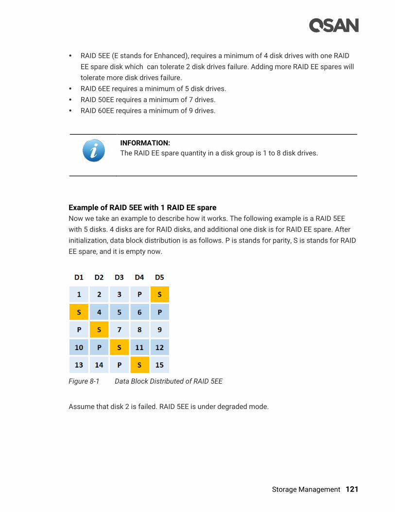
Storage Management 121
RAID 5EE (E stands for Enhanced), requires a minimum of 4 disk drives with one RAID
EE spare disk which can tolerate 2 disk drives failure. Adding more RAID EE spares will
tolerate more disk drives failure.
RAID 6EE requires a minimum of 5 disk drives.
RAID 50EE requires a minimum of 7 drives.
RAID 60EE requires a minimum of 9 drives.
INFORMATION:
The RAID EE spare quantity in a disk group is 1 to 8 disk drives.
Example of RAID 5EE with 1 RAID EE spare
Now we take an example to describe how it works. The following example is a RAID 5EE
with 5 disks. 4 disks are for RAID disks, and additional one disk is for RAID EE spare. After
initialization, data block distribution is as follows. P is stands for parity, S is stands for RAID
EE spare, and it is empty now.
Figure 8-1 Data Block Distributed of RAID 5EE
Assume that disk 2 is failed. RAID 5EE is under degraded mode.

122 © Copyright 2018 QSAN Technology, Inc. All Right Reserved.
Figure 8-2 Disk 2 is Failed
The spare areas are rebuilt with data from the failed disk drive. This action is called EE
Rebuild. After rebuild, data distributed is like RAID 5 and it can tolerate another failed disk
drive. As we can imagine, the more RAID EE spare disks, the faster it rebuilds.
Figure 8-3 Empty Blocks are Rebuilt from the Failed Disk Drive
When a new disk drive is joined into the RAID EE disk group, the data rebuilt in the spare
area will be copied back to the new disk. This action is called Copyback.

Storage Management 123
Figure 8-4 Data is copied back
After copied back, it is back to RAID 5EE normal state.
Example of RAID 60EE with 2 RAID EE spares
Take another example of a RAID 60EE with 10 disks. 8 disks are for RAID disks, and 2 disks
are for RAID EE spares. After initialization, data block distribution is as follows.
Figure 8-5 Data Block Distributed of RAID 60EE

124 © Copyright 2018 QSAN Technology, Inc. All Right Reserved.
Rebuild and copy back of RAID 60EE is similar as the above; it will not be repeated here.
RAID EE Level Summary
The following is the summary of the RAID EE levels.
Table 8-3 RAID EE Level Summary
RAID 5EE RAID 6EE RAID 50EE RAID 60EE
Min. Drives 4 5 7 9
Data Protection One drive
failure
Two drive
failure
One drive
failure
Two drive
failure
Read Performance Very Good Very Good Very Good Very Good
Write Performance Good Fair to Good Good Fair to Good
Capacity
(N = drive quantity,
M = drive capacity,
G = subgroups,
S = RAID EE spares)
(N-1-S) x M
(e.g., (10 drives –
1 – 2 spares) x
1TB = 7TB)
(N-2-S) x M
(e.g., (10 drives - 2
-2 spares) x 1TB =
6TB)
(N-G-S) x M
(e.g., (10 drives - 2
subgroups - 2
spares) x 1TB =
6TB)
(N-2xG-S) x M
(e.g., (10 drives - 2
x 2 subgroups - 2
spares) x 1TB =
4TB)
Capacity Utilization
(Min.~26 drives)
18%~92%
(e.g., 7/10 = 70%)
17%~88%
(e.g., 6/10 = 60%)
29%~88%
(e.g., 6/10 = 60%)
25%~80%
(e.g., 4/10 = 40%)
Typical
Applications
Same as RAID
5
Same as RAID
6
Same as RAID
50
Same as RAID
60
INFORMATION:
RAID EE technology is available in SANOS firmware 1.3.0.
8.2. SANOS Storage Architecture
This section describes the SANOS storage architecture including pool, volume, LUN
mapping, and hot spares.
8.2.1. Pool Technology
A storage pool is a collection of disk drives. It has three pool types which are listed in the
following.

Storage Management 125
Thick or fat provisioning pool, we use the term of thick provisioning pool in the following.
Thin provisioning pool
Auto tiering pool
We describe thick provisioning pool here, and introduce thin provisioning in the Thin
Provisioning chapter and auto tiering in the Auto Tiering chapter.
A thick provisioning pool is a collection of disk groups which contain disk drives and made
up a RAID. A storage pool is grouped to provide capacity for volumes. Volumes are then
allocated out of the storage pool and are mapped to LUN which can be accessed by a host
system. The following is the storage architecture of a thick provisioning pool.
Figure 8-6 Storage Architecture of Thick Provisioning Pool
In thick provisioning pool, there are two methods to increase the capacity of the pool. They
are migration or adding disk groups. For migration, disk drives can be added to a disk group
at any time, no matter the disk drives are from the head SAN system or from expansion
units. Or disk drives can be added to upgrade the RAID level in a thick provisioning pool. For
example, you can migrate RAID 5 to RAID 6 by adding disk drives because RAID 6 needs one
more disk drive for parity.
The other method is adding other disk groups which contain disk drives to increase the
capacity of the pool. A thick provisioning pool can have up to 32 disk groups with each disk
group containing up to 64 disk drives. And the maximum disk drive quantity in a pool is 256.
For more information about pool operation, please refer to the chapter 8.4, Configuring
Thick Provisioning Pools section.

126 © Copyright 2018 QSAN Technology, Inc. All Right Reserved.
INFORMATION:
To support disk group storage architecture in thick provisioning pool
starts from SANOS firmware 1.2.0.
Table 8-4 Thick Provisioning Pool Parameters
Item Value
Maximum disk group quantity in a pool 32
Maximum disk drive quantity in a disk group
(include dedicated spares)
64
Maximum RAID EE spare quantity in a disk group 8
Maximum disk drive quantity in a pool
(include dedicated spares)
256
Maximum pool quantity per system 64
Maximum dedicated spare quantity in a pool 8
Maximum addressable capacity of a disk group 640TB
(calculated by 10TB HDD)
Maximum addressable capacity of a thick provisioning pool 2,560TB
(calculated by 10TB HDD)
Maximum addressable capacity of total thick provisioning
pools
Unlimited
8.2.2. Migrate vs. Add Disk Group
In thick provisioning pool, there are two methods to increase the capacity of the pool.
Migration takes a long time and risk during migration. But after migration, it is more efficient
than adding disk groups. By this way, it can also migrate RAID level to get a better protection.
With adding disk group, it can increase the capacity immediately but cannot change the
quantity or RAID level after adding this disk group. User can evaluate the advantages and
disadvantages to choose the best way.
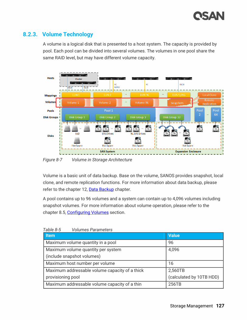
Storage Management 127
8.2.3. Volume Technology
A volume is a logical disk that is presented to a host system. The capacity is provided by
pool. Each pool can be divided into several volumes. The volumes in one pool share the
same RAID level, but may have different volume capacity.
Figure 8-7 Volume in Storage Architecture
Volume is a basic unit of data backup. Base on the volume, SANOS provides snapshot, local
clone, and remote replication functions. For more information about data backup, please
refer to the chapter 12, Data Backup chapter.
A pool contains up to 96 volumes and a system can contain up to 4,096 volumes including
snapshot volumes. For more information about volume operation, please refer to the
chapter 8.5, Configuring Volumes section.
Table 8-5 Volumes Parameters
Item Value
Maximum volume quantity in a pool 96
Maximum volume quantity per system
(include snapshot volumes)
4,096
Maximum host number per volume 16
Maximum addressable volume capacity of a thick
provisioning pool
2,560TB
(calculated by 10TB HDD)
Maximum addressable volume capacity of a thin 256TB
128 © Copyright 2018 QSAN Technology, Inc. All Right Reserved.
provisioning pool
Maximum addressable volume capacity of an auto tiering
pool
256TB
8.2.4. LUN Technology
LUN (Logical Unit Number) is a number used to identify a logical unit, which is a device
addressed by the SCSI protocol or Storage Area Network protocols which encapsulate SCSI,
such as Fibre Channel or iSCSI.
The LUN is not the only way to identify a logical unit. There is also the SCSI device ID, which
identifies a logical unit uniquely in the world. Labels or serial numbers stored in a logical
unit's storage volume often serve to identify the logical unit. However, the LUN is the only
way for an initiator to address a command to a particular logical unit, so initiators often
create, via a discovery process, a mapping table of LUN to other identifiers.
There is one LUN which is required to exist in every target: LUN 0. The logical unit with LUN
0 is special in that it must implement a few specific commands, most notably report LUNs,
which is how an initiator can find out all the other LUNs in the target. LUN 0 does not
provide any other services, such as a storage volume. Many SCSI targets contain only one
logical unit (so its LUN is necessarily 0). Others have a small number of logical units that
correspond to separate physical devices and have fixed LUNs. A large storage system may
have up to thousands of logical units, defined logically, by administrative command, and the
administrator may choose the LUN or the system may choose it.

Storage Management 129
Figure 8-8 LUM Mappings in Storage Architecture
Volumes are then allocated out of the storage pool and are mapped to LUN which can be
accessed by a host system. In Figure 8-3, a LUN can be accessed by cluster with two or
more hosts via iSCSI. Or can be accessed by MPIO to provide HA (High Availability)
architecture and increase the access bandwidth. The snapshot volumes can also be
mapped to a LUN. The same, the read-only snapshot LUN can be read by the host, and the
writable snapshot LUN can be read/write.
A SANOS system can contain up to 4,096 LUNs which includes the total of volume LUN
mappings and snapshot volume LUN mappings.
Table 8-6 LUN Parameters
Item Value
Maximum LUN quantity per system 4,096
For more information about LUN mapping operation, please refer to the chapter 8.6,
Configure LUN Mappings section.
8.2.5. Hot Spares
A hot spare disk is a disk used to automatically or manually replace a failing or failed disk in
a RAID configuration. The hot spare disk reduces the MTTR (Mean Time To Recovery) for
the RAID redundancy group, thus reducing the probability of a second disk failure and the
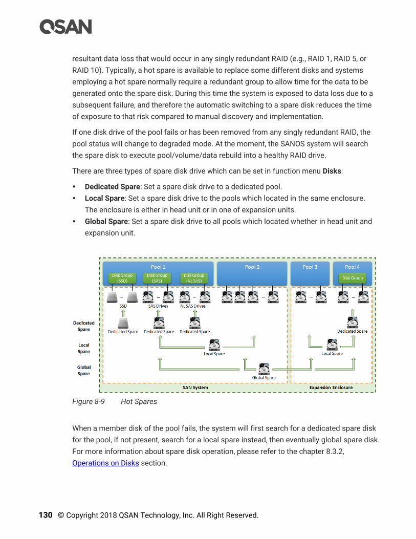
130 © Copyright 2018 QSAN Technology, Inc. All Right Reserved.
resultant data loss that would occur in any singly redundant RAID (e.g., RAID 1, RAID 5, or
RAID 10). Typically, a hot spare is available to replace some different disks and systems
employing a hot spare normally require a redundant group to allow time for the data to be
generated onto the spare disk. During this time the system is exposed to data loss due to a
subsequent failure, and therefore the automatic switching to a spare disk reduces the time
of exposure to that risk compared to manual discovery and implementation.
If one disk drive of the pool fails or has been removed from any singly redundant RAID, the
pool status will change to degraded mode. At the moment, the SANOS system will search
the spare disk to execute pool/volume/data rebuild into a healthy RAID drive.
There are three types of spare disk drive which can be set in function menu Disks:
Dedicated Spare: Set a spare disk drive to a dedicated pool.
Local Spare: Set a spare disk drive to the pools which located in the same enclosure.
The enclosure is either in head unit or in one of expansion units.
Global Spare: Set a spare disk drive to all pools which located whether in head unit and
expansion unit.
Figure 8-9 Hot Spares
When a member disk of the pool fails, the system will first search for a dedicated spare disk
for the pool, if not present, search for a local spare instead, then eventually global spare disk.
For more information about spare disk operation, please refer to the chapter 8.3.2,
Operations on Disks section.
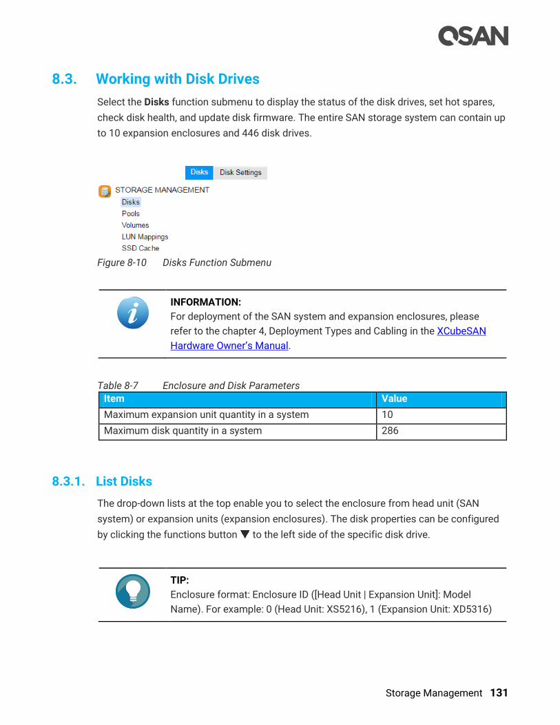
Storage Management 131
8.3. Working with Disk Drives
Select the Disks function submenu to display the status of the disk drives, set hot spares,
check disk health, and update disk firmware. The entire SAN storage system can contain up
to 10 expansion enclosures and 446 disk drives.
Figure 8-10 Disks Function Submenu
INFORMATION:
For deployment of the SAN system and expansion enclosures, please
refer to the chapter 4, Deployment Types and Cabling in the XCubeSAN
Hardware Owner’s Manual.
Table 8-7 Enclosure and Disk Parameters
Item Value
Maximum expansion unit quantity in a system 10
Maximum disk quantity in a system 286
8.3.1. List Disks
The drop-down lists at the top enable you to select the enclosure from head unit (SAN
system) or expansion units (expansion enclosures). The disk properties can be configured
by clicking the functions button to the left side of the specific disk drive.
TIP:
Enclosure format: Enclosure ID ([Head Unit | Expansion Unit]: Model
Name). For example: 0 (Head Unit: XS5216), 1 (Expansion Unit: XD5316)
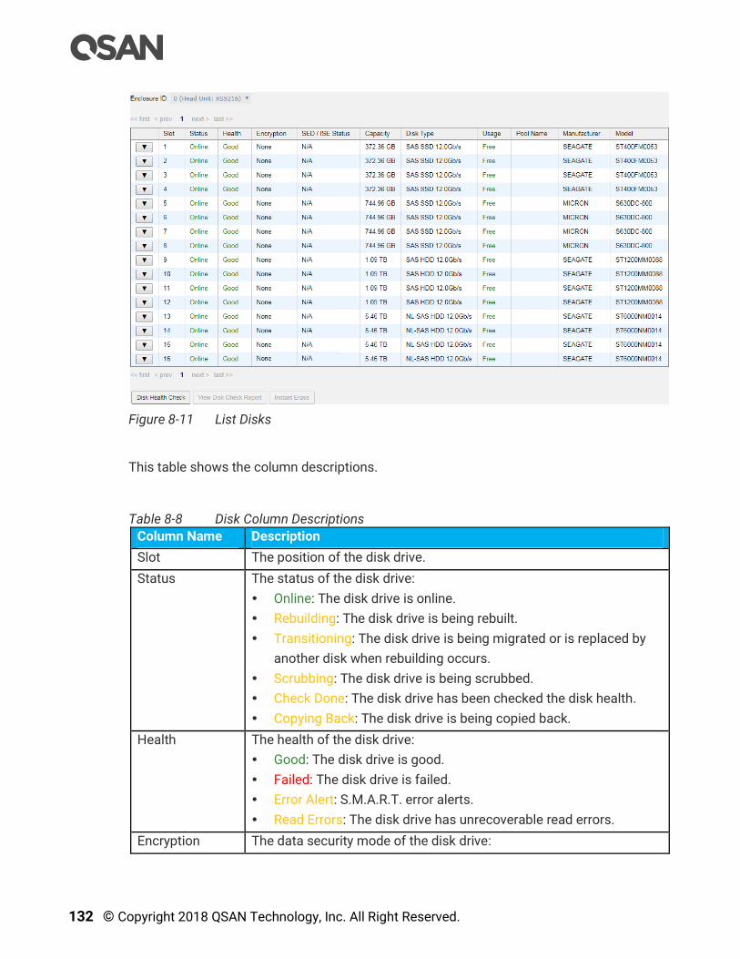
132 © Copyright 2018 QSAN Technology, Inc. All Right Reserved.
Figure 8-11 List Disks
This table shows the column descriptions.
Table 8-8 Disk Column Descriptions
Column Name Description
Slot The position of the disk drive.
Status The status of the disk drive:
Online: The disk drive is online.
Rebuilding: The disk drive is being rebuilt.
Transitioning: The disk drive is being migrated or is replaced by
another disk when rebuilding occurs.
Scrubbing: The disk drive is being scrubbed.
Check Done: The disk drive has been checked the disk health.
Copying Back: The disk drive is being copied back.
Health The health of the disk drive:
Good: The disk drive is good.
Failed: The disk drive is failed.
Error Alert: S.M.A.R.T. error alerts.
Read Errors: The disk drive has unrecoverable read errors.
Encryption The data security mode of the disk drive:
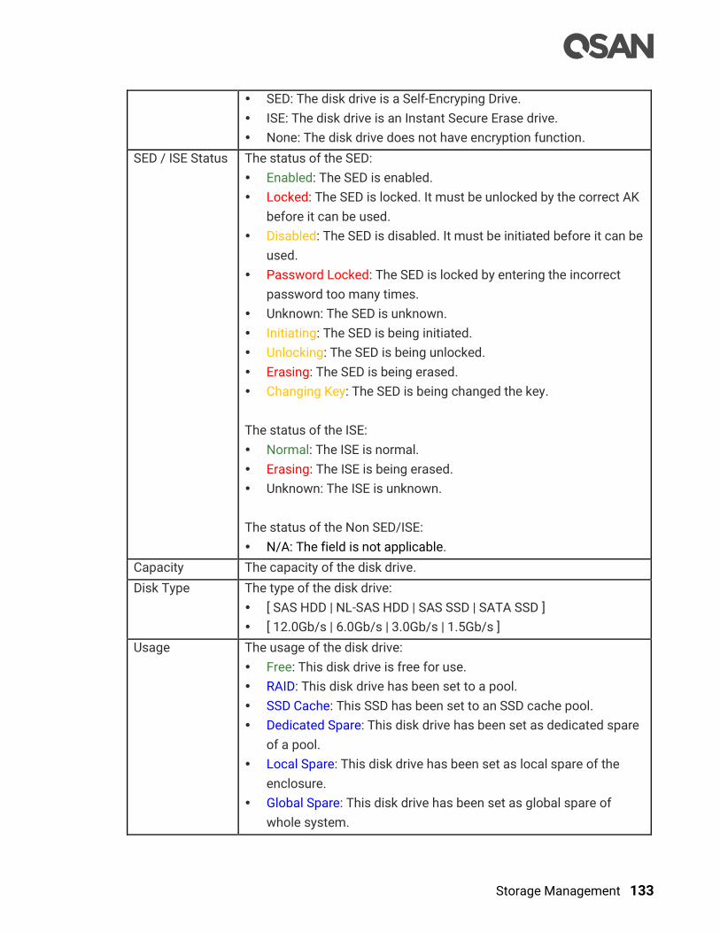
Storage Management 133
SED: The disk drive is a Self-Encryping Drive.
ISE: The disk drive is an Instant Secure Erase drive.
None: The disk drive does not have encryption function.
SED / ISE Status The status of the SED:
Enabled: The SED is enabled.
Locked: The SED is locked. It must be unlocked by the correct AK
before it can be used.
Disabled: The SED is disabled. It must be initiated before it can be
used.
Password Locked: The SED is locked by entering the incorrect
password too many times.
Unknown: The SED is unknown.
Initiating: The SED is being initiated.
Unlocking: The SED is being unlocked.
Erasing: The SED is being erased.
Changing Key: The SED is being changed the key.
The status of the ISE:
Normal: The ISE is normal.
Erasing: The ISE is being erased.
Unknown: The ISE is unknown.
The status of the Non SED/ISE:
N/A: The field is not applicable.
Capacity The capacity of the disk drive.
Disk Type The type of the disk drive:
[ SAS HDD | NL-SAS HDD | SAS SSD | SATA SSD ]
[ 12.0Gb/s | 6.0Gb/s | 3.0Gb/s | 1.5Gb/s ]
Usage The usage of the disk drive:
Free: This disk drive is free for use.
RAID: This disk drive has been set to a pool.
SSD Cache: This SSD has been set to an SSD cache pool.
Dedicated Spare: This disk drive has been set as dedicated spare
of a pool.
Local Spare: This disk drive has been set as local spare of the
enclosure.
Global Spare: This disk drive has been set as global spare of
whole system.
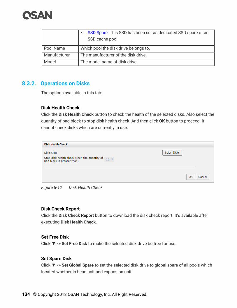
134 © Copyright 2018 QSAN Technology, Inc. All Right Reserved.
SSD Spare: This SSD has been set as dedicated SSD spare of an
SSD cache pool.
Pool Name Which pool the disk drive belongs to.
Manufacturer The manufacturer of the disk drive.
Model The model name of disk drive.
8.3.2. Operations on Disks
The options available in this tab:
Disk Health Check
Click the Disk Health Check button to check the health of the selected disks. Also select the
quantity of bad block to stop disk health check. And then click OK button to proceed. It
cannot check disks which are currently in use.
Figure 8-12 Disk Health Check
Disk Check Report
Click the Disk Check Report button to download the disk check report. It’s available after
executing Disk Health Check.
Set Free Disk
Click ▼ -> Set Free Disk to make the selected disk drive be free for use.
Set Spare Disk
Click ▼ -> Set Global Spare to set the selected disk drive to global spare of all pools which
located whether in head unit and expansion unit.

Storage Management 135
Click ▼ -> Set Local Spare to set the selected disk drive to local spare of the pools which
located in the same enclosure. The enclosure is either in head unit or in one of expansion
units.
Click ▼ -> Set Dedicated Spare to set the disk drive to dedicated spare of the selected pool.
For more information about hot spares, please refer to the chapter 8.2.4, Hot Spares section
and the chapter 15.2, Rebuild section in the Troubleshooting chapter. Here is an example
how to set a spare disk to a dedicated pool.
1. Select a free disk, and then click ▼ -> Set Dedicated Spare.
Figure 8-13 Set Dedicated Spare
2. Select the pool which the disk drive is set to its dedicated spare, and then click OK
button.
Disk Scrub and Clear Disk Read Error
Click ▼ -> Disk Scrub to scrub the disk drive. It’s not available when the disk drive is in used.
Click ▼ -> Clear Disk Read Error to clean the read error of the disk drive and reset the failed
status.
Update Disk Firmware
Click ▼ -> Update Disk Firmware to upgrade the firmware of the disk drive.

136 © Copyright 2018 QSAN Technology, Inc. All Right Reserved.
Figure 8-14 Update Disk Firmware
Turn on Disk LED
Click ▼ -> Turn on Disk LED to turn on the indication LED of the disk drive.
Turn off Disk LED
Click ▼ -> Turn off Disk LED to turn off the indication LED of the disk drive.
S.M.A.R.T.
Click ▼ -> S.M.A.R.T. to show the S.M.A.R.T. information of the disk drive. For more
information about S.M.A.R.T., please refer to the chapter 8.3.3, S.M.A.R.T. section
More Information of the Disk
Click ▼ -> More Information to show the detail information of the disk drive.
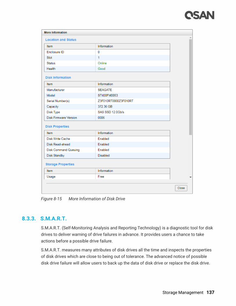
Storage Management 137
Figure 8-15 More Information of Disk Drive
8.3.3. S.M.A.R.T.
S.M.A.R.T. (Self-Monitoring Analysis and Reporting Technology) is a diagnostic tool for disk
drives to deliver warning of drive failures in advance. It provides users a chance to take
actions before a possible drive failure.
S.M.A.R.T. measures many attributes of disk drives all the time and inspects the properties
of disk drives which are close to being out of tolerance. The advanced notice of possible
disk drive failure will allow users to back up the data of disk drive or replace the disk drive.
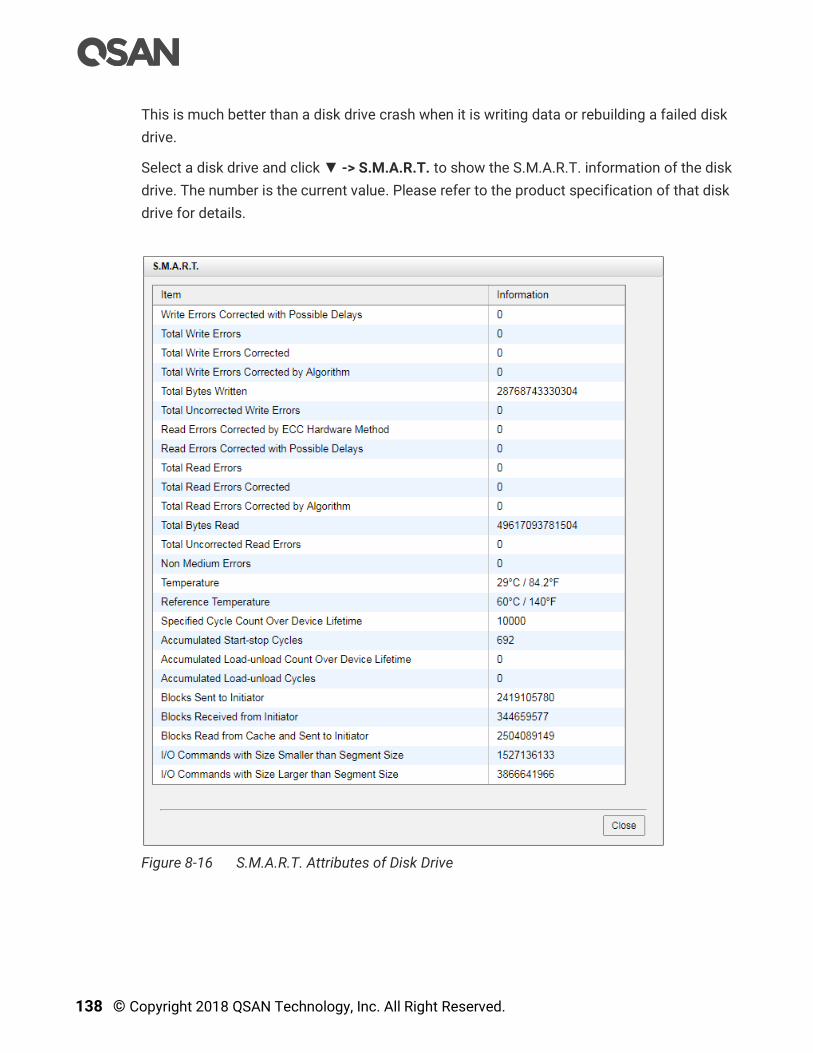
138 © Copyright 2018 QSAN Technology, Inc. All Right Reserved.
This is much better than a disk drive crash when it is writing data or rebuilding a failed disk
drive.
Select a disk drive and click ▼ -> S.M.A.R.T. to show the S.M.A.R.T. information of the disk
drive. The number is the current value. Please refer to the product specification of that disk
drive for details.
Figure 8-16 S.M.A.R.T. Attributes of Disk Drive

Storage Management 139
Figure 8-17 S.M.A.R.T. Attributes of SSD
For some SSDs, we provide SSD endurance values to monitor the health of SSDs. The value is a percentage to know how much remaining life of SSD is. The system will notify user if the SSD endurance is under 10%. And also 5%, 3%, 2% by sequence.
TIP:
Although it’s a useful reference value to know the remaining life of the
SSD, we recommend replacing the SSD if the value is under 5%.
INFORMATION:
SAS/SATA SSD Endurance for monitoring the life remaining is available in
SANOS firmware 1.2.0.
S.M.A.R.T. Polling
Select the Disk Settings function submenu to configure the S.M.A.R.T. polling setting.
Uncheck the Enable S.M.A.R.T. Polling to disable S.M.A.R.T. polling setting. Disabling
S.M.A.R.T. polling will let system not report any problems if there were any S.M.A.R.T. error.
There are 2 options when enabling the S.M.A.R.T. polling setting. Selecting the Inquiry
option will let system report problems of disk when discovering S.M.A.R.T. error and show
in event log to inform customers. Selecting the Inquiry and Action option will allow system
to report problems of disk when discovering S.M.A.R.T. error and show in event log to
inform customers, and then the system will remove the problematic disk drive from the pool.
The pool will be rebuilt by using a spare disk drive.

140 © Copyright 2018 QSAN Technology, Inc. All Right Reserved.
Figure 8-18 Disk Settings
INFORMATION:
S.M.A.R.T. polling setting is available in SANOS firmware 1.3.0.
8.4. Configure Thick Provisioning Pools
Select the Pools function submenu to create, modify, delete, or view the status of the pools.
We will describe thick provisioning pool in the following section; keep thin provisioning
technology in the Thin Provisioning chapter and auto tiering in the Auto Tiering chapter.
Figure 8-19 Pools Function Submenu
8.4.1. Create a Thick Provisioning Pool
Here is an example of creating a thick provisioning pool with 4 disks configured in RAID 5.
At the first time of creating a thick provisioning pool, it contains a disk group and the
maximum quantity of disk in a disk group is 64.
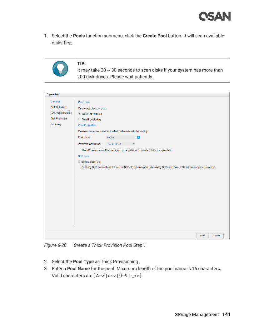
Storage Management 141
1. Select the Pools function submenu, click the Create Pool button. It will scan available
disks first.
TIP:
It may take 20 ~ 30 seconds to scan disks if your system has more than
200 disk drives. Please wait patiently.
Figure 8-20 Create a Thick Provision Pool Step 1
2. Select the Pool Type as Thick Provisioning.
3. Enter a Pool Name for the pool. Maximum length of the pool name is 16 characters.
Valid characters are [ A~Z | a~z | 0~9 | -_<> ].

142 © Copyright 2018 QSAN Technology, Inc. All Right Reserved.
4. Select a Preferred Controller from the drop-down list. The backend I/O resources in this
pool will be processed by the preferred controller which you specified. This option is
available when dual controllers are installed.
5. Check the Enable SED Pool checkbox. Enabling SED pool will use the secure SEDs to
create a pool. Intermixing SEDs and non-SEDs are not supported in a pool.
6. Click the Next button to continue.
Figure 8-21 Create a Thick Provision Pool Step 2
7. Please select disks for pool. The maximum quantity of disk in a disk group is 64. Select
an Enclosure ID from the drop-down list to select disks from expansion enclosures.
8. Click the Next button to continue.

Storage Management 143
Figure 8-22 Create a Thick Provision Pool Step 3
9. Select a RAID Level from the drop-down list which lists available RAID level only
according to the disk selection. And also select a Quantity of Subgroups if the
combination RAID level is selected.
10. Click the Next button to continue.

144 © Copyright 2018 QSAN Technology, Inc. All Right Reserved.
Figure 8-23 Create a Thick Provision Pool Step 4
11. Disk properties can also be configured optionally in this step:
。 Enable Disk Write Cache: Check to enable the write cache option of disks. Enabling
disk write cache will improve write I/O performance but have a risk of losing data
when power failure.
。 Enable Disk Read-ahead: Check to enable the read-ahead function of disks. System
will preload data to disk buffer based on previously retrieved data. This feature will
efficiently improve the performance of sequential data retrieved.
。 Enable Disk Command Queuing: Check to enable the command queue function of
disks. Send multiple commands to a disk at once to improve performance.
。 Enable Disk Standby: Check to enable the auto spin down function of disks. The
disks will be spun down for power saving when they are idle for the period of time
specified.
12. Click the Next button to continue.
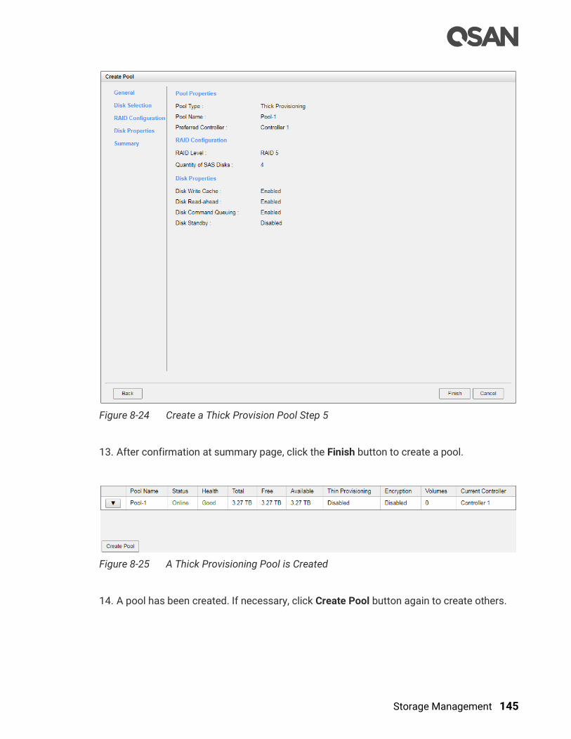
Storage Management 145
Figure 8-24 Create a Thick Provision Pool Step 5
13. After confirmation at summary page, click the Finish button to create a pool.
Figure 8-25 A Thick Provisioning Pool is Created
14. A pool has been created. If necessary, click Create Pool button again to create others.
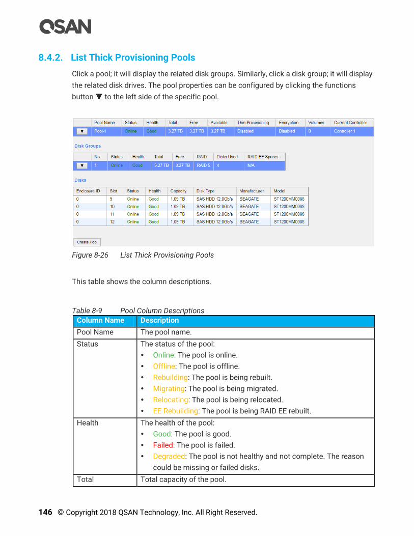
146 © Copyright 2018 QSAN Technology, Inc. All Right Reserved.
8.4.2. List Thick Provisioning Pools
Click a pool; it will display the related disk groups. Similarly, click a disk group; it will display
the related disk drives. The pool properties can be configured by clicking the functions
button to the left side of the specific pool.
Figure 8-26 List Thick Provisioning Pools
This table shows the column descriptions.
Table 8-9 Pool Column Descriptions
Column Name Description
Pool Name The pool name.
Status The status of the pool:
Online: The pool is online.
Offline: The pool is offline.
Rebuilding: The pool is being rebuilt.
Migrating: The pool is being migrated.
Relocating: The pool is being relocated.
EE Rebuilding: The pool is being RAID EE rebuilt.
Health The health of the pool:
Good: The pool is good.
Failed: The pool is failed.
Degraded: The pool is not healthy and not complete. The reason
could be missing or failed disks.
Total Total capacity of the pool.

Storage Management 147
Free Free capacity of the pool.
Available Available capacity of the pool.
Thin
Provisioning
The status of Thin provisioning:
Disabled.
Enabled.
Encryption The Data Secure Mode:
Disabled: The pool is not encrypted.
Enabled: The pool is encrypted.
Volumes The quantity of volumes in the pool.
Current
Controller
(This option is
only visible when
dual controllers
are installed.)
The current running controller of the pool.
Table 8-10 Disk Group Column Descriptions
Column Name Description
No. The number of the disk group.
Status The status of the disk group:
Online: The disk group is online.
Offline: The disk group is offline.
Rebuilding: The disk group is being rebuilt.
Migrating: The disk group is being migrated.
Relocating: The disk group is being relocated.
EE Rebuilding: The disk group is being RAID EE rebuilt.
Health The health of the disk group:
Good: The disk group is good.
Failed: The disk group fails.
Degraded: The pool is not healthy and not complete. The reason
could be missing or failed disks.
Total Total capacity of the disk group.
Free Free capacity of the disk group.
RAID The RAID level of the disk group.
Disks Used The quantity of disk drives in the disk group.
RAID EE Spare The quantity of RAID EE spare disk drives in the disk group. Display
N/A is the RAID level is traditional.
Table 8-11 Disk Column Descriptions
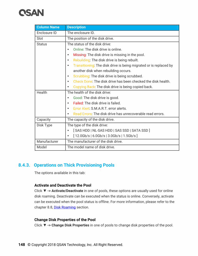
148 © Copyright 2018 QSAN Technology, Inc. All Right Reserved.
Column Name Description
Enclosure ID The enclosure ID.
Slot The position of the disk drive.
Status The status of the disk drive:
Online: The disk drive is online.
Missing: The disk drive is missing in the pool.
Rebuilding: The disk drive is being rebuilt.
Transitioning: The disk drive is being migrated or is replaced by
another disk when rebuilding occurs.
Scrubbing: The disk drive is being scrubbed.
Check Done: The disk drive has been checked the disk health.
Copying Back: The disk drive is being copied back.
Health The health of the disk drive:
Good: The disk drive is good.
Failed: The disk drive is failed.
Error Alert: S.M.A.R.T. error alerts.
Read Errors: The disk drive has unrecoverable read errors.
Capacity The capacity of the disk drive.
Disk Type The type of the disk drive:
[ SAS HDD | NL-SAS HDD | SAS SSD | SATA SSD ]
[ 12.0Gb/s | 6.0Gb/s | 3.0Gb/s | 1.5Gb/s ]
Manufacturer The manufacturer of the disk drive.
Model The model name of disk drive.
8.4.3. Operations on Thick Provisioning Pools
The options available in this tab:
Activate and Deactivate the Pool
Click ▼ -> Activate/Deactivate in one of pools, these options are usually used for online
disk roaming. Deactivate can be executed when the status is online. Conversely, activate
can be executed when the pool status is offline. For more information, please refer to the
chapter 8.8, Disk Roaming section.
Change Disk Properties of the Pool
Click ▼ -> Change Disk Properties in one of pools to change disk properties of the pool.
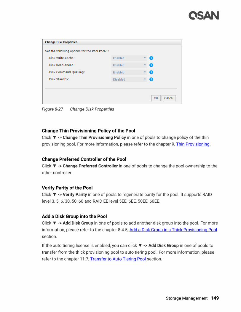
Storage Management 149
Figure 8-27 Change Disk Properties
Change Thin Provisioning Policy of the Pool
Click ▼ -> Change Thin Provisioning Policy in one of pools to change policy of the thin
provisioning pool. For more information, please refer to the chapter 9, Thin Provisioning.
Change Preferred Controller of the Pool
Click ▼ -> Change Preferred Controller in one of pools to change the pool ownership to the
other controller.
Verify Parity of the Pool
Click ▼ -> Verify Parity in one of pools to regenerate parity for the pool. It supports RAID
level 3, 5, 6, 30, 50, 60 and RAID EE level 5EE, 6EE, 50EE, 60EE.
Add a Disk Group into the Pool
Click ▼ -> Add Disk Group in one of pools to add another disk group into the pool. For more
information, please refer to the chapter 8.4.5, Add a Disk Group in a Thick Provisioning Pool
section.
If the auto tiering license is enabled, you can click ▼ -> Add Disk Group in one of pools to
transfer from the thick provisioning pool to auto tiering pool. For more information, please
refer to the chapter 11.7, Transfer to Auto Tiering Pool section.
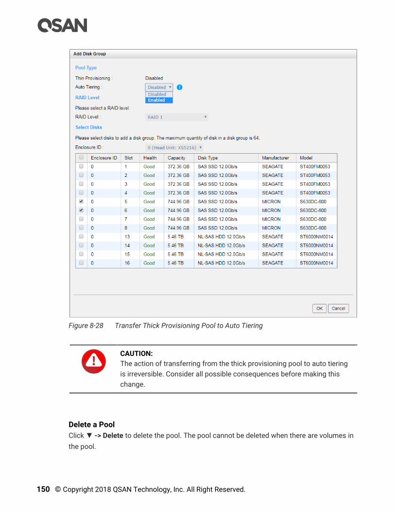
150 © Copyright 2018 QSAN Technology, Inc. All Right Reserved.
Figure 8-28 Transfer Thick Provisioning Pool to Auto Tiering
CAUTION:
The action of transferring from the thick provisioning pool to auto tiering
is irreversible. Consider all possible consequences before making this
change.
Delete a Pool
Click ▼ -> Delete to delete the pool. The pool cannot be deleted when there are volumes in
the pool.
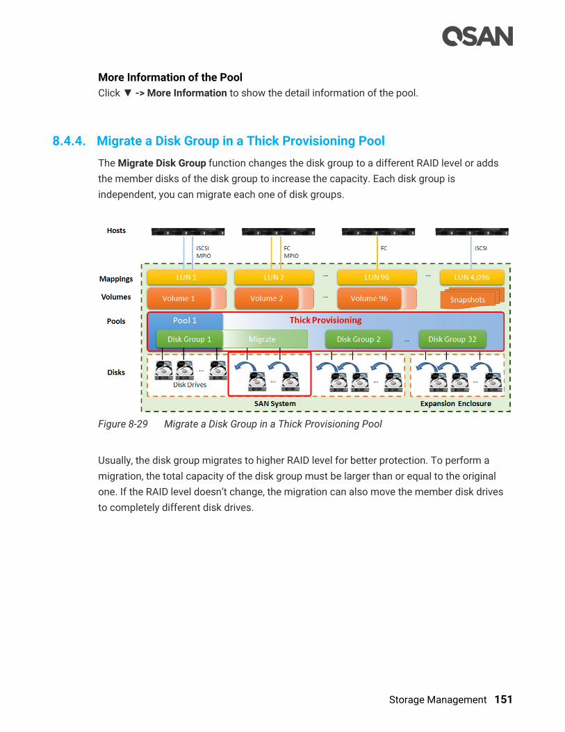
Storage Management 151
More Information of the Pool
Click ▼ -> More Information to show the detail information of the pool.
8.4.4. Migrate a Disk Group in a Thick Provisioning Pool
The Migrate Disk Group function changes the disk group to a different RAID level or adds
the member disks of the disk group to increase the capacity. Each disk group is
independent, you can migrate each one of disk groups.
Figure 8-29 Migrate a Disk Group in a Thick Provisioning Pool
Usually, the disk group migrates to higher RAID level for better protection. To perform a
migration, the total capacity of the disk group must be larger than or equal to the original
one. If the RAID level doesn’t change, the migration can also move the member disk drives
to completely different disk drives.
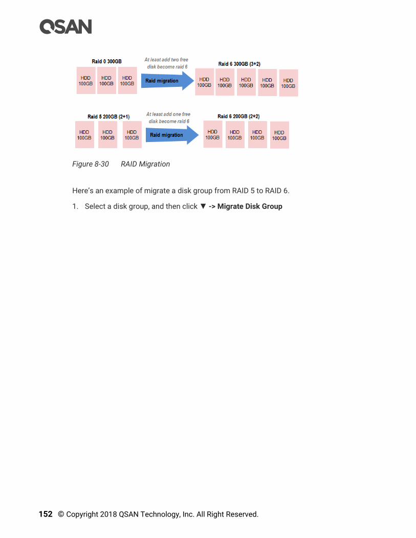
152 © Copyright 2018 QSAN Technology, Inc. All Right Reserved.
Figure 8-30 RAID Migration
Here’s an example of migrate a disk group from RAID 5 to RAID 6.
1. Select a disk group, and then click ▼ -> Migrate Disk Group

Storage Management 153
Figure 8-31 Migrate RAID Level Step 1
2. Select a RAID Level from the drop-down list.
3. Please select disks for pool. The maximum quantity of disk in a disk group is 64. Select
an Enclosure ID from the drop-down list to select disks from expansion enclosures.
4. Click the OK button to execute migration.
5. Migration starts. The status of the Disks, Pools and Volumes are changing. The
complete percentage of migration is displayed in the Status.
6. It’s done when the complete percentage reaches 100%.

154 © Copyright 2018 QSAN Technology, Inc. All Right Reserved.
TIP:
The capacity after migration must be larger than the current capacity.
TIP:
A traditional RAID level can be migrated to RAID EE level, but RAID EE level
can be migrated to RAID EE level only.
TIP:
Thin provisioning pool cannot execute the Migrate Disk Group option; it
uses the Add Disk Group option to enlarge the capacity. For more
information, please refer to the chapter 9, Thin Provisioning.
Operation Limitations during Migration
There are some operation limitations when a pool is being migrated. The System would
reject these operations:
Add dedicated spare.
Remove a dedicated spare.
Create a new volume.
Delete a volume.
Extend a volume.
Scrub a volume.
Perform another migration operation.
Scrub entire pool.
Take a snapshot.
Delete a snapshot.
Expose a snapshot.
Rollback to a snapshot.
TIP:
Pool migration cannot be executed during rebuilding or volume extension.

Storage Management 155
8.4.5. Add a Disk Group in a Thick Provisioning Pool
The Add Disk Group function adds a disk group to a pool to increase the capacity.
Figure 8-32 Add a Disk Group in a Thick Provisioning Pool
Here is an example of adding a disk group into a thick provisioning pool with 2 disks
configured in RAID 1.
1. Select a pool, click ▼ -> Add Disk Group to add a disk group in a thick provisioning pool.

156 © Copyright 2018 QSAN Technology, Inc. All Right Reserved.
Figure 8-33 Add a Disk Group to a Thick Provisioning Pool
2. Select a RAID Level from the drop-down list and also select a Quantity of Subgroups if
the combination RAID level is selected.
3. Select disks to add into a disk group. The maximum quantity of disk in a disk group is 64.
Select an Enclosure ID from the drop-down list to select disks from expansion
enclosures.
4. Click the OK button to add a disk group into the pool.
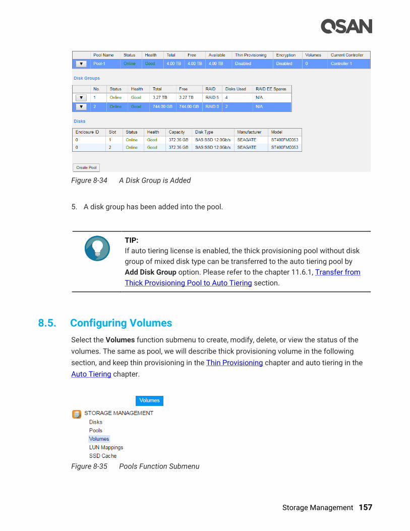
Storage Management 157
Figure 8-34 A Disk Group is Added
5. A disk group has been added into the pool.
TIP:
If auto tiering license is enabled, the thick provisioning pool without disk
group of mixed disk type can be transferred to the auto tiering pool by
Add Disk Group option. Please refer to the chapter 11.6.1, Transfer from
Thick Provisioning Pool to Auto Tiering section.
8.5. Configuring Volumes
Select the Volumes function submenu to create, modify, delete, or view the status of the
volumes. The same as pool, we will describe thick provisioning volume in the following
section, and keep thin provisioning in the Thin Provisioning chapter and auto tiering in the
Auto Tiering chapter.
Figure 8-35 Pools Function Submenu

158 © Copyright 2018 QSAN Technology, Inc. All Right Reserved.
8.5.1. Create a Volume
Here is an example of creating a volume in think provisioning Pool.
1. Select the Volumes function submenu, click the Create Volume button.
Figure 8-36 Create a Volume in Thick Provisioning Pool Step 1
2. Enter a Volume Name for the pool. The maximum length of the volume name is 32
characters. Valid characters are [ A~Z | a~z | 0~9 | -_<> ].
3. Select a Pool Name from the drop-down list. It will also display the available capacity of
the pool.
4. Enter required Capacity. The unit can be selected from the drop-down list.
5. Select the Volume Type. The options are RAID Volume (for general RAID usage) and
Backup Volume (for the target volume of local clone or remote replication).
6. Click the Next button to continue.
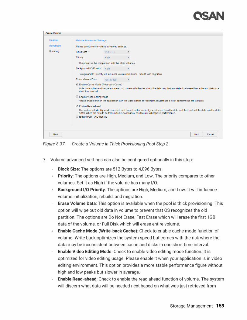
Storage Management 159
Figure 8-37 Create a Volume in Thick Provisioning Pool Step 2
7. Volume advanced settings can also be configured optionally in this step:
。 Block Size: The options are 512 Bytes to 4,096 Bytes.
。 Priority: The options are High, Medium, and Low. The priority compares to other
volumes. Set it as High if the volume has many I/O.
。 Background I/O Priority: The options are High, Medium, and Low. It will influence
volume initialization, rebuild, and migration.
。 Erase Volume Data: This option is available when the pool is thick provisioning. This
option will wipe out old data in volume to prevent that OS recognizes the old
partition. The options are Do Not Erase, Fast Erase which will erase the first 1GB
data of the volume, or Full Disk which will erase entire volume.
。 Enable Cache Mode (Write-back Cache): Check to enable cache mode function of
volume. Write back optimizes the system speed but comes with the risk where the
data may be inconsistent between cache and disks in one short time interval.
。 Enable Video Editing Mode: Check to enable video editing mode function. It is
optimized for video editing usage. Please enable it when your application is in video
editing environment. This option provides a more stable performance figure without
high and low peaks but slower in average.
。 Enable Read-ahead: Check to enable the read ahead function of volume. The system
will discern what data will be needed next based on what was just retrieved from

160 © Copyright 2018 QSAN Technology, Inc. All Right Reserved.
disk and then preload this data into the disk's buffer. This feature will improve
performance when the data being retrieved is sequential.
。 Enable Fast RAID Rebuild: This option is available when the pool is created in
protection RAID level (e.g., RAID 1, 3, 5, 6, 0+1, 10, 30, 50, and 60). For more
information, please refer to the chapter 8.5.5, Fast RAID Rebuild section.
8. Click the Next button to continue.
Figure 8-38 Create a Volume in Thick Provisioning Pool Step 3
9. After confirmation at summary page, click the Finish button to create a volume.
10. The volume has been created. It will be initialized in protection RAID level (e.g., RAID 1, 3,
5, 6, 0+1, 10, 30, 50, and 60).
Figure 8-39 A Volume in Thick Provisioning Pool is Created and Initializing

Storage Management 161
11. A volume has been created. If necessary, click Create Volume button to create another.
TIP:
SANOS supports instant RAID volume availability. The volume can be
used immediately when it is initializing or rebuilding.
TIP:
If the pool contains some disk drives of 4Kn type, it is not available to set
512, 1024, or 2048 block size. When the case happens, it will pop up a
warning message and suggest changing the block size to 4096.
8.5.2. List Volumes
Select one of the volumes; it will display the related LUN Mappings if the volume is mapped.
The volume properties can be configured by clicking the functions button to the left side
of the specific volume.
Figure 8-40 List Volumes
This table shows the column descriptions.
Table 8-12 Volume Column Descriptions
Column Name Description
Volume Name The volume name.
Status The status of the volume:
Online: The volume is online.
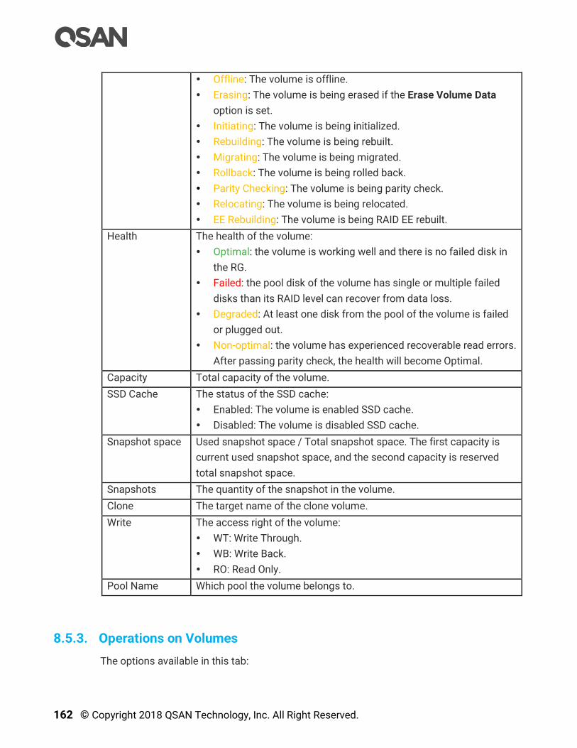
162 © Copyright 2018 QSAN Technology, Inc. All Right Reserved.
Offline: The volume is offline.
Erasing: The volume is being erased if the Erase Volume Data
option is set.
Initiating: The volume is being initialized.
Rebuilding: The volume is being rebuilt.
Migrating: The volume is being migrated.
Rollback: The volume is being rolled back.
Parity Checking: The volume is being parity check.
Relocating: The volume is being relocated.
EE Rebuilding: The volume is being RAID EE rebuilt.
Health The health of the volume:
Optimal: the volume is working well and there is no failed disk in
the RG.
Failed: the pool disk of the volume has single or multiple failed
disks than its RAID level can recover from data loss.
Degraded: At least one disk from the pool of the volume is failed
or plugged out.
Non-optimal: the volume has experienced recoverable read errors.
After passing parity check, the health will become Optimal.
Capacity Total capacity of the volume.
SSD Cache The status of the SSD cache:
Enabled: The volume is enabled SSD cache.
Disabled: The volume is disabled SSD cache.
Snapshot space Used snapshot space / Total snapshot space. The first capacity is
current used snapshot space, and the second capacity is reserved
total snapshot space.
Snapshots The quantity of the snapshot in the volume.
Clone The target name of the clone volume.
Write The access right of the volume:
WT: Write Through.
WB: Write Back.
RO: Read Only.
Pool Name Which pool the volume belongs to.
8.5.3. Operations on Volumes
The options available in this tab:
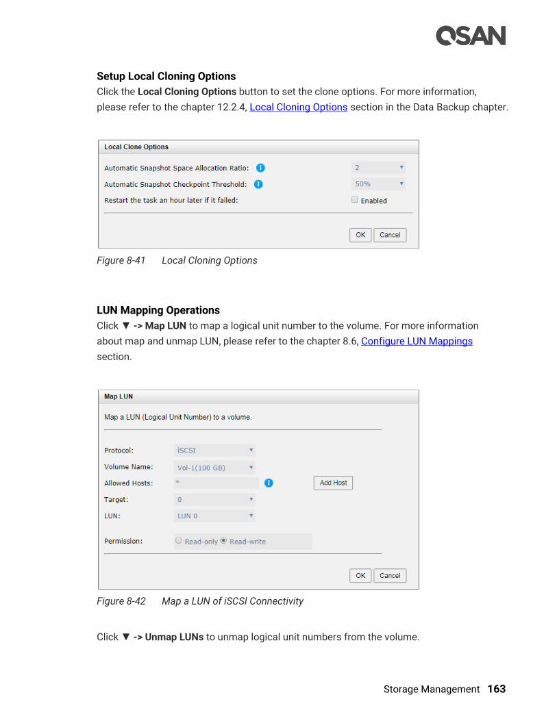
Storage Management 163
Setup Local Cloning Options
Click the Local Cloning Options button to set the clone options. For more information,
please refer to the chapter 12.2.4, Local Cloning Options section in the Data Backup chapter.
Figure 8-41 Local Cloning Options
LUN Mapping Operations
Click ▼ -> Map LUN to map a logical unit number to the volume. For more information
about map and unmap LUN, please refer to the chapter 8.6, Configure LUN Mappings
section.
Figure 8-42 Map a LUN of iSCSI Connectivity
Click ▼ -> Unmap LUNs to unmap logical unit numbers from the volume.

164 © Copyright 2018 QSAN Technology, Inc. All Right Reserved.
Figure 8-43 Unmap LUNs
Snapshot Operations
Click ▼ -> Set Snapshot Space to set snapshot space for preparing to take snapshots. For
more information about snapshot, please refer to the chapter 12.1, Managing Snapshots
section in the Data Backup chapter.
Figure 8-44 Set Snapshot Space
Click ▼ -> Take Snapshot to take a snapshot of the volume.
Click ▼ -> Schedule Snapshots to set the snapshots by schedule.
Click ▼ -> List Snapshots to list all snapshots of the volume.
Click ▼ -> Cleanup Snapshots to clean all snapshots of the volume and release the
snapshot space.

Storage Management 165
Local Clone Operations
Click ▼ -> Create Local Clone to set the target volume for clone. For more information
about local clone, please refer to the chapter 12.2, Managing Local Clones section in the
Data Backup chapter.
Figure 8-45 Create Local Clone
Click ▼ -> Clear Clone to clear the clone.
Click ▼ -> Start Clone to start the clone.
Click ▼ -> Stop Clone to stop the clone.
Click ▼ -> Schedule Clone to set the clone function by schedule.
Click ▼ -> Change Replication Options to change the clone to Replication relationship. For
more information about remote replication, please refer to the chapter 12.3, Managing
Remote Replications section in the Data Backup chapter.
SSD Cache Options
Click ▼ -> Enable SSD Cache to enable SSD cache for the volume. For more information
about SSD cache, please refer to the chapter 10, SSD Cache chapter.
Click ▼ -> Disable SSD Cache to disable SSD cache for the volume.
Change Volume Properties
Click ▼ -> Change Volume Properties to change the volume properties of the volume.
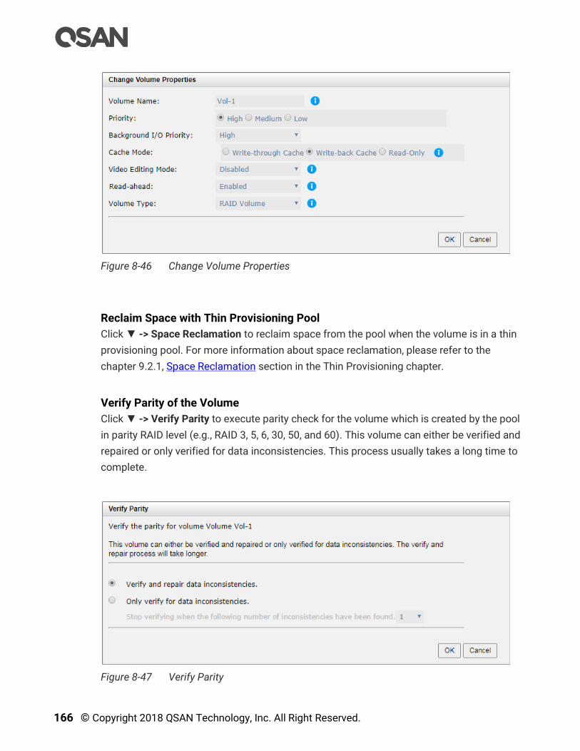
166 © Copyright 2018 QSAN Technology, Inc. All Right Reserved.
Figure 8-46 Change Volume Properties
Reclaim Space with Thin Provisioning Pool
Click ▼ -> Space Reclamation to reclaim space from the pool when the volume is in a thin
provisioning pool. For more information about space reclamation, please refer to the
chapter 9.2.1, Space Reclamation section in the Thin Provisioning chapter.
Verify Parity of the Volume
Click ▼ -> Verify Parity to execute parity check for the volume which is created by the pool
in parity RAID level (e.g., RAID 3, 5, 6, 30, 50, and 60). This volume can either be verified and
repaired or only verified for data inconsistencies. This process usually takes a long time to
complete.
Figure 8-47 Verify Parity
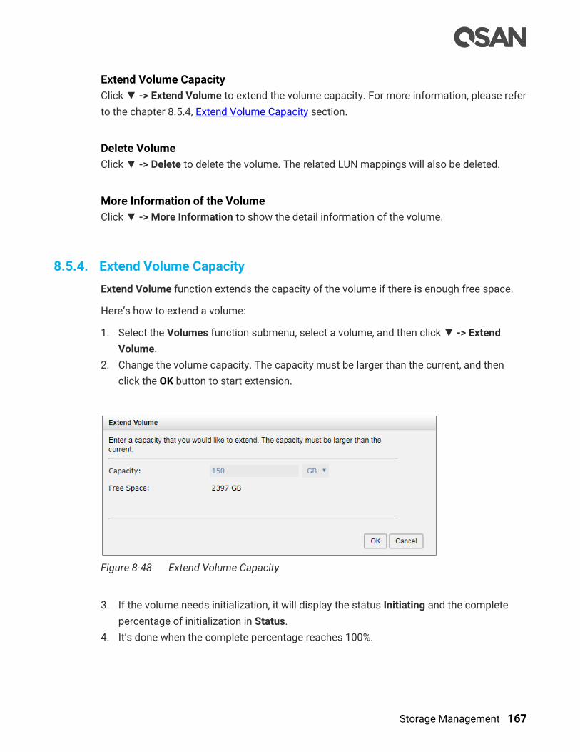
Storage Management 167
Extend Volume Capacity
Click ▼ -> Extend Volume to extend the volume capacity. For more information, please refer
to the chapter 8.5.4, Extend Volume Capacity section.
Delete Volume
Click ▼ -> Delete to delete the volume. The related LUN mappings will also be deleted.
More Information of the Volume
Click ▼ -> More Information to show the detail information of the volume.
8.5.4. Extend Volume Capacity
Extend Volume function extends the capacity of the volume if there is enough free space.
Here’s how to extend a volume:
1. Select the Volumes function submenu, select a volume, and then click ▼ -> Extend
Volume.
2. Change the volume capacity. The capacity must be larger than the current, and then
click the OK button to start extension.
Figure 8-48 Extend Volume Capacity
3. If the volume needs initialization, it will display the status Initiating and the complete
percentage of initialization in Status.
4. It’s done when the complete percentage reaches 100%.
168 © Copyright 2018 QSAN Technology, Inc. All Right Reserved.
TIP:
The extension capacity must be larger than the current capacity.
TIP:
Extension cannot be executed during rebuilding or migration.
8.5.5. Fast RAID Rebuild
When executing rebuild, the Fast RAID Rebuild feature skips any partition of the volume
where no write changes have occurred, it will focus only on the parts that have changed.
This mechanism may reduce the amount of time needed for the rebuild task. It also reduces
the risk of RAID failure cause of reducing the time required for the RAID status from
degraded mode to healthy. At the same time, it frees up CPU resources more quickly to be
available for other I/O and demands. For more information, please refer to the Fast Rebuild
White Paper.
Enable Fast RAID Rebuild
Here is an example of enabling the Fast RAID Rebuild function when creating a volume.
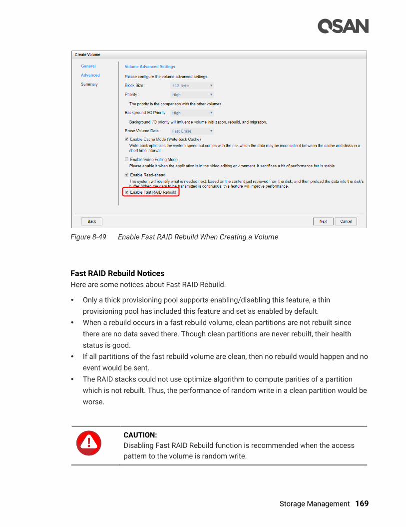
Storage Management 169
Figure 8-49 Enable Fast RAID Rebuild When Creating a Volume
Fast RAID Rebuild Notices
Here are some notices about Fast RAID Rebuild.
Only a thick provisioning pool supports enabling/disabling this feature, a thin
provisioning pool has included this feature and set as enabled by default.
When a rebuild occurs in a fast rebuild volume, clean partitions are not rebuilt since
there are no data saved there. Though clean partitions are never rebuilt, their health
status is good.
If all partitions of the fast rebuild volume are clean, then no rebuild would happen and no
event would be sent.
The RAID stacks could not use optimize algorithm to compute parities of a partition
which is not rebuilt. Thus, the performance of random write in a clean partition would be
worse.
CAUTION:
Disabling Fast RAID Rebuild function is recommended when the access
pattern to the volume is random write.

170 © Copyright 2018 QSAN Technology, Inc. All Right Reserved.
8.6. Configure LUN Mappings
Select the LUN Mappings function submenu to map, unmap or view the status of LUN
(Logical Unit Number) for each volume.
Figure 8-50 Pools Function Submenu
8.6.1. Map a LUN of iSCSI Connectivity
Here’s an example of mapping a LUN of iSCSI connectivity.
1. Select the LUN Mappings function submenu, click the Map LUN button.
Figure 8-51 Map a LUN of iSCSI Connectivity
2. Select the Protocol as iSCSI.
3. Select a Volume from the drop-down list.
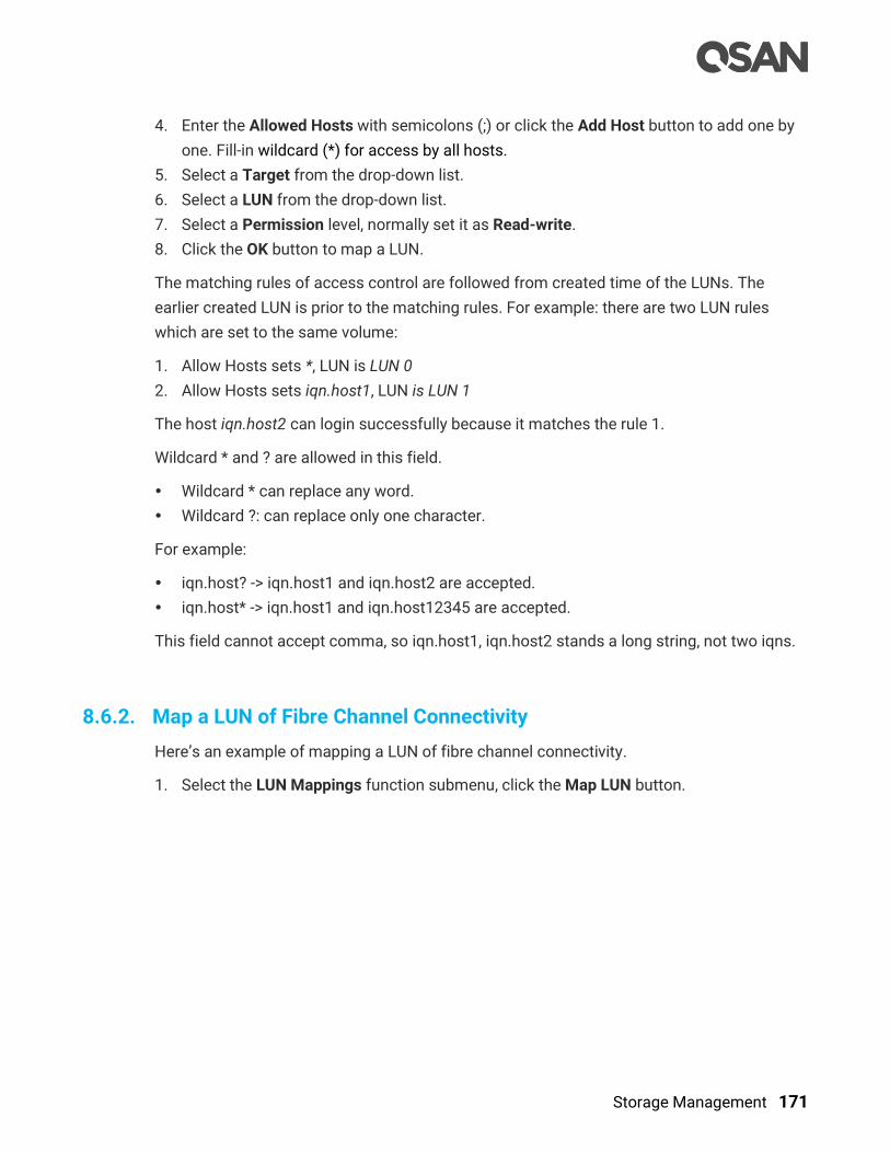
Storage Management 171
4. Enter the Allowed Hosts with semicolons (;) or click the Add Host button to add one by
one. Fill-in wildcard (*) for access by all hosts.
5. Select a Target from the drop-down list.
6. Select a LUN from the drop-down list.
7. Select a Permission level, normally set it as Read-write.
8. Click the OK button to map a LUN.
The matching rules of access control are followed from created time of the LUNs. The
earlier created LUN is prior to the matching rules. For example: there are two LUN rules
which are set to the same volume:
1. Allow Hosts sets *, LUN is LUN 0
2. Allow Hosts sets iqn.host1, LUN is LUN 1
The host iqn.host2 can login successfully because it matches the rule 1.
Wildcard * and ? are allowed in this field.
Wildcard * can replace any word.
Wildcard ?: can replace only one character.
For example:
iqn.host? -> iqn.host1 and iqn.host2 are accepted.
iqn.host* -> iqn.host1 and iqn.host12345 are accepted.
This field cannot accept comma, so iqn.host1, iqn.host2 stands a long string, not two iqns.
8.6.2. Map a LUN of Fibre Channel Connectivity
Here’s an example of mapping a LUN of fibre channel connectivity.
1. Select the LUN Mappings function submenu, click the Map LUN button.
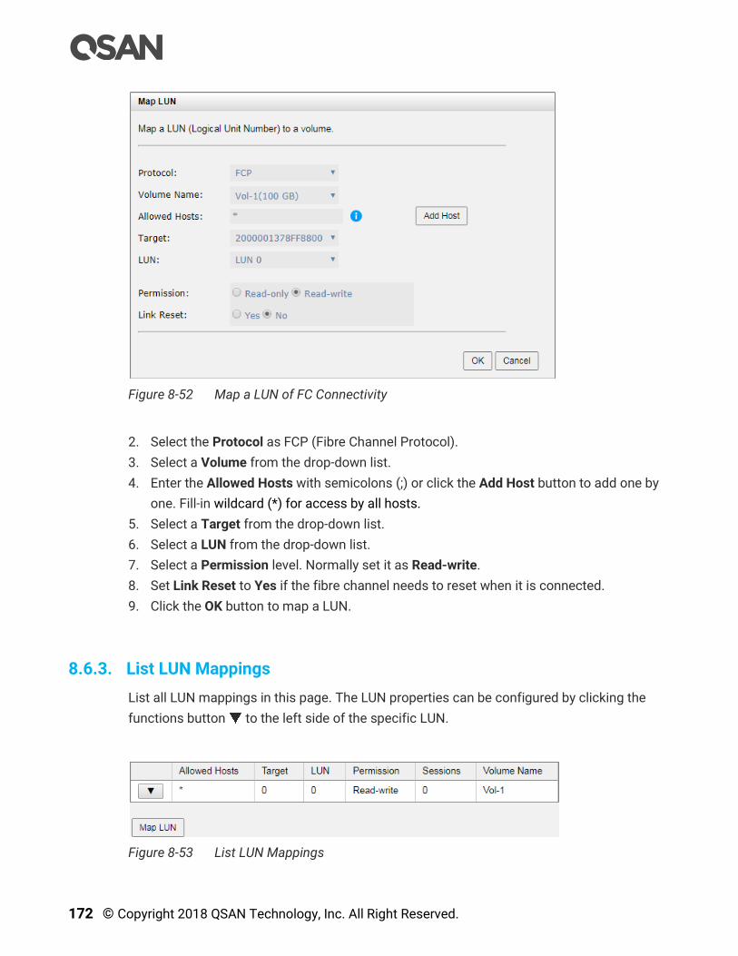
172 © Copyright 2018 QSAN Technology, Inc. All Right Reserved.
Figure 8-52 Map a LUN of FC Connectivity
2. Select the Protocol as FCP (Fibre Channel Protocol).
3. Select a Volume from the drop-down list.
4. Enter the Allowed Hosts with semicolons (;) or click the Add Host button to add one by
one. Fill-in wildcard (*) for access by all hosts.
5. Select a Target from the drop-down list.
6. Select a LUN from the drop-down list.
7. Select a Permission level. Normally set it as Read-write.
8. Set Link Reset to Yes if the fibre channel needs to reset when it is connected.
9. Click the OK button to map a LUN.
8.6.3. List LUN Mappings
List all LUN mappings in this page. The LUN properties can be configured by clicking the
functions button to the left side of the specific LUN.
Figure 8-53 List LUN Mappings
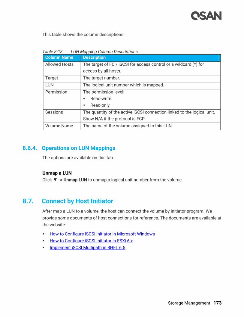
Storage Management 173
This table shows the column descriptions.
Table 8-13 LUN Mapping Column Descriptions
Column Name Description
Allowed Hosts The target of FC / iSCSI for access control or a wildcard (*) for
access by all hosts.
Target The target number.
LUN The logical unit number which is mapped.
Permission The permission level:
Read-write
Read-only
Sessions The quantity of the active iSCSI connection linked to the logical unit.
Show N/A if the protocol is FCP.
Volume Name The name of the volume assigned to this LUN.
8.6.4. Operations on LUN Mappings
The options are available on this tab:
Unmap a LUN
Click ▼ -> Unmap LUN to unmap a logical unit number from the volume.
8.7. Connect by Host Initiator
After map a LUN to a volume, the host can connect the volume by initiator program. We
provide some documents of host connections for reference. The documents are available at
the website:
How to Configure iSCSI Initiator in Microsoft Windows
How to Configure iSCSI Initiator in ESXi 6.x
Implement iSCSI Multipath in RHEL 6.5
174 © Copyright 2018 QSAN Technology, Inc. All Right Reserved.
8.8. Disk Roaming
Disks can be re-sequenced in the same system or move all member disks in the same pool
from system-1 to system-2. This is called disk roaming. System can execute disk roaming
online. Please follow these steps.
1. Select the Pools function submenu, selects a pool. And then click ▼ -> Deactivate.
2. Click the OK button to apply. The Status changes to Offline.
3. Move all member disks of the pool to another system.
4. In Volumes tab, select the pool. And then click ▼ -> Activate.
5. Click the OK button to apply. The Status changes to Online.
Disk roaming has some constraints as described in the following.
1. Check the firmware version of two systems first. It is better for both systems to have the
same firmware version or the firmware version of the system-2 is newer.
2. All physical disks of the pool should be moved from system-1 to system-2 together. The
configuration of both pool and volume will be kept but LUN configuration will be cleared
in order to avoid conflict with the current setting of the system-2.
INFORMATION:
XCubeSAN series does NOT support disk roaming from AegisSAN LX,
AegisSAN Q500, nor AegisSAN V100.
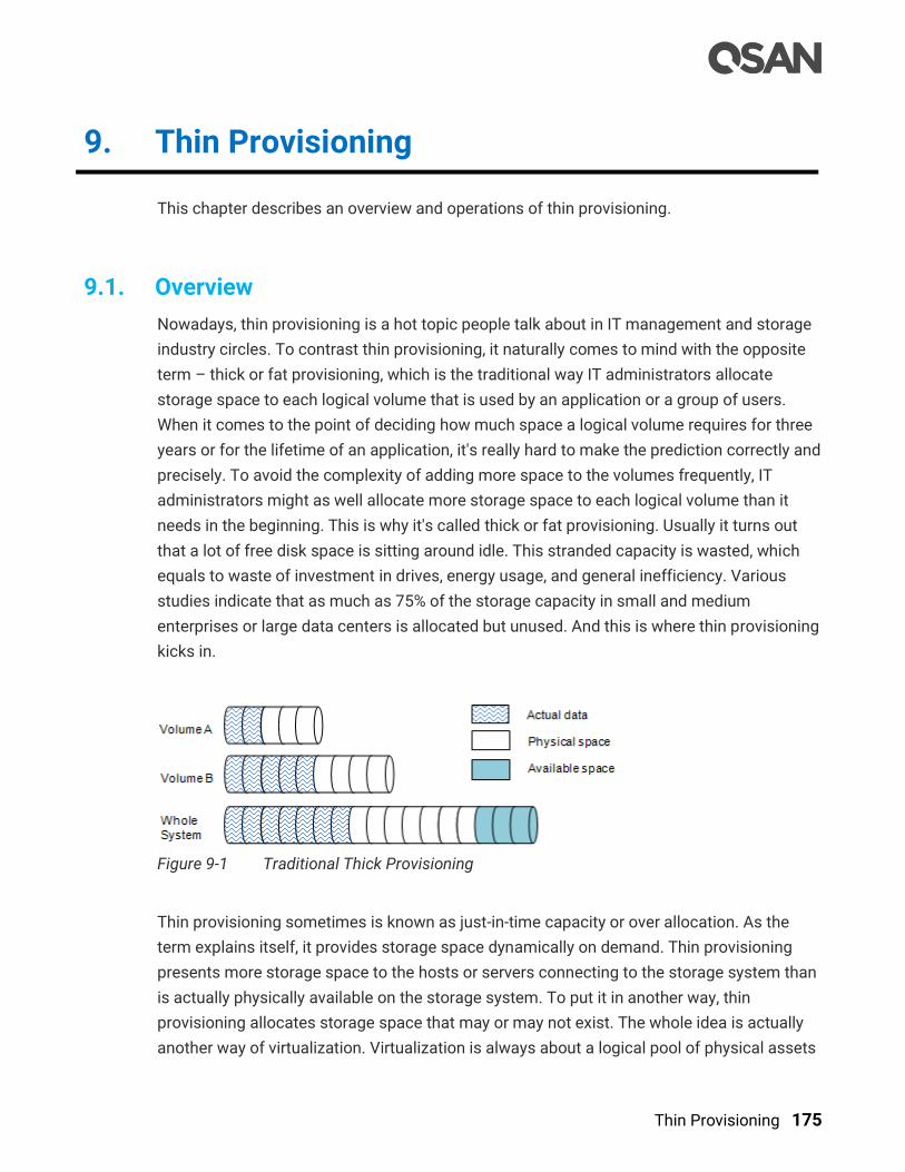
Thin Provisioning 175
9. Thin Provisioning
This chapter describes an overview and operations of thin provisioning.
9.1. Overview
Nowadays, thin provisioning is a hot topic people talk about in IT management and storage
industry circles. To contrast thin provisioning, it naturally comes to mind with the opposite
term – thick or fat provisioning, which is the traditional way IT administrators allocate
storage space to each logical volume that is used by an application or a group of users.
When it comes to the point of deciding how much space a logical volume requires for three
years or for the lifetime of an application, it's really hard to make the prediction correctly and
precisely. To avoid the complexity of adding more space to the volumes frequently, IT
administrators might as well allocate more storage space to each logical volume than it
needs in the beginning. This is why it's called thick or fat provisioning. Usually it turns out
that a lot of free disk space is sitting around idle. This stranded capacity is wasted, which
equals to waste of investment in drives, energy usage, and general inefficiency. Various
studies indicate that as much as 75% of the storage capacity in small and medium
enterprises or large data centers is allocated but unused. And this is where thin provisioning
kicks in.
Figure 9-1 Traditional Thick Provisioning
Thin provisioning sometimes is known as just-in-time capacity or over allocation. As the
term explains itself, it provides storage space dynamically on demand. Thin provisioning
presents more storage space to the hosts or servers connecting to the storage system than
is actually physically available on the storage system. To put it in another way, thin
provisioning allocates storage space that may or may not exist. The whole idea is actually
another way of virtualization. Virtualization is always about a logical pool of physical assets

176 © Copyright 2018 QSAN Technology, Inc. All Right Reserved.
and provides better utilization over those assets. Here the virtualization mechanism behind
thin provisioning is storage pool. The capacity of the storage pool is shared by all volumes.
When write requests come in, the space will be drawn dynamically from this storage pool to
meet the needs.
Figure 9-2 Thin Provisioning
9.1.1. Thick Provisioning vs. Thin Provisioning
The efficiency of thin or thick provisioning is a function of the use case, not of the
technology. Thick provisioning is typically more efficient when the amount of resource used
very closely approximates to the amount of resource allocated. Thin provisioning offers
more efficiency where the amount of resource used is much smaller than allocated, so that
the benefit of providing only the resource needed exceeds the cost of the virtualization
technology used.
Figure 9-3 Benefits of Thin Provisioning
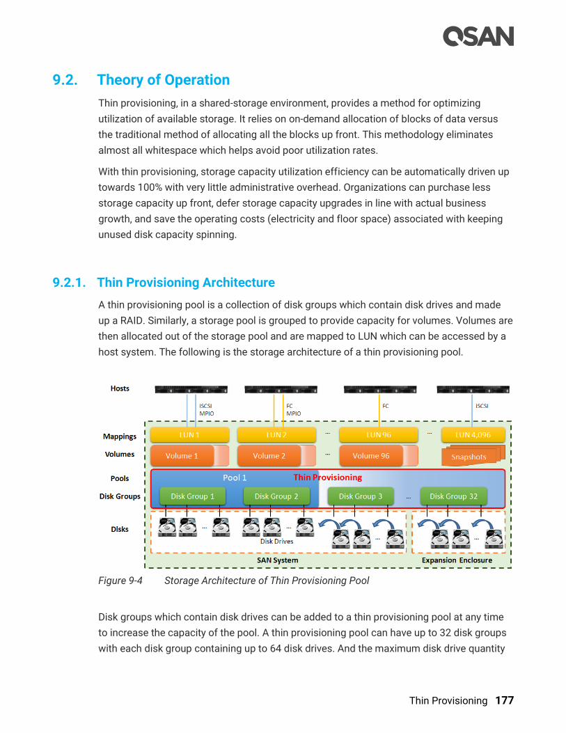
Thin Provisioning 177
9.2. Theory of Operation
Thin provisioning, in a shared-storage environment, provides a method for optimizing
utilization of available storage. It relies on on-demand allocation of blocks of data versus
the traditional method of allocating all the blocks up front. This methodology eliminates
almost all whitespace which helps avoid poor utilization rates.
With thin provisioning, storage capacity utilization efficiency can be automatically driven up
towards 100% with very little administrative overhead. Organizations can purchase less
storage capacity up front, defer storage capacity upgrades in line with actual business
growth, and save the operating costs (electricity and floor space) associated with keeping
unused disk capacity spinning.
9.2.1. Thin Provisioning Architecture
A thin provisioning pool is a collection of disk groups which contain disk drives and made
up a RAID. Similarly, a storage pool is grouped to provide capacity for volumes. Volumes are
then allocated out of the storage pool and are mapped to LUN which can be accessed by a
host system. The following is the storage architecture of a thin provisioning pool.
Figure 9-4 Storage Architecture of Thin Provisioning Pool
Disk groups which contain disk drives can be added to a thin provisioning pool at any time
to increase the capacity of the pool. A thin provisioning pool can have up to 32 disk groups
with each disk group containing up to 64 disk drives. And the maximum disk drive quantity

178 © Copyright 2018 QSAN Technology, Inc. All Right Reserved.
in a pool is 256. The maximum addressable capacity of each disk group is 64TB. So the
maximum capacity in a system is 256TB. For more information about pool operation, please
refer to the chapter 9.3, Configuring Thin Provisioning Pools section.
Table 9-1 Thin Provisioning Pool Parameters
Item Value
Maximum disk group quantity in a pool 32
Maximum disk drive quantity in a disk group
(include dedicated spares)
64
Maximum RAID EE spare quantity in a disk group 8
Maximum disk drive quantity in a pool
(include dedicated spares)
256
Maximum pool quantity per system 64
Maximum dedicated spare quantity in a pool 8
Maximum addressable capacity of a disk group 64TB
Maximum addressable capacity of a thin provisioning pool 256TB
Maximum addressable capacity of total thin provisioning
pools
(include auto tiering pools)
1,024TB
Provisioning granularity 1GB
9.2.2. Space Reclamation
Previously allocated, but currently unused volume space can be reclaimed in disk pools
after all data within a granularity have been deleted from volumes by hosts. Data must be
permanently deleted to be considered as unused space. The unused space is returned to
the pool.
Similar to the manual operation of reclaiming volume pace is the auto-reclamation process,
which is the continual process of automatically reclaiming spaces that are "not in use" or
"zeroed-out" and returning them to the pool without user intervention. The auto-reclamation
process has some benefits over running the manual operation. For more information about
the operation, refer to the chapter 9.4.1, Create a Volume in a Thin Provisioning Pool section.

Thin Provisioning 179
9.2.3. Thin Provisioning Policies
Because thin provisioning is just-in-time capacity or over allocation, thin provisioning polices
have been designed to warn in advance. There are 6 levels of threshold percentage and the
default values defined as the following table.
Table 9-2 Thin Provisioning Policies and Default Values
No. Threshold Level Action
1 60% Information Take no Action
2 70% Information Take no Action
3 80% Information Take no Action
4 85% Warning Reclaim Space
5 90% Warning Delete Snapshots
6 95% Warning De-activate Pool
When the used capacity of the thin provisioning pool reaches 60%, the system will send an
event with information level to inform users. This is the same as 70% and 80%. To 85%, in
addition to the system issued an event with warning level, but also began to implement
space reclamation. After reaching 90%, it starts deleting the snapshot to keep the incoming
data space. If it reaches 95%, the pool will be deactivated to avoid data loss.
The event log levels and actions can be changed when the usage of the pool capacity
reaches the threshold. For more information about the operation, refer to the chapter 9.3.3,
Operations on Thin Provisioning Pools section.
CAUTION:
Please always watch the system logs of thin provisioning pool. If the used
capacity of the thin provisioning pool reaches 95%, the system will
deactivate the pool to avoid data loss. So the host cannot access the pool
at this time. You have to expand the pool capacity, and then activate the
pool to resolve the issue.
9.3. Configure Thin Provisioning Pools
This section will describe the operations of configuring thin provisioning pool.
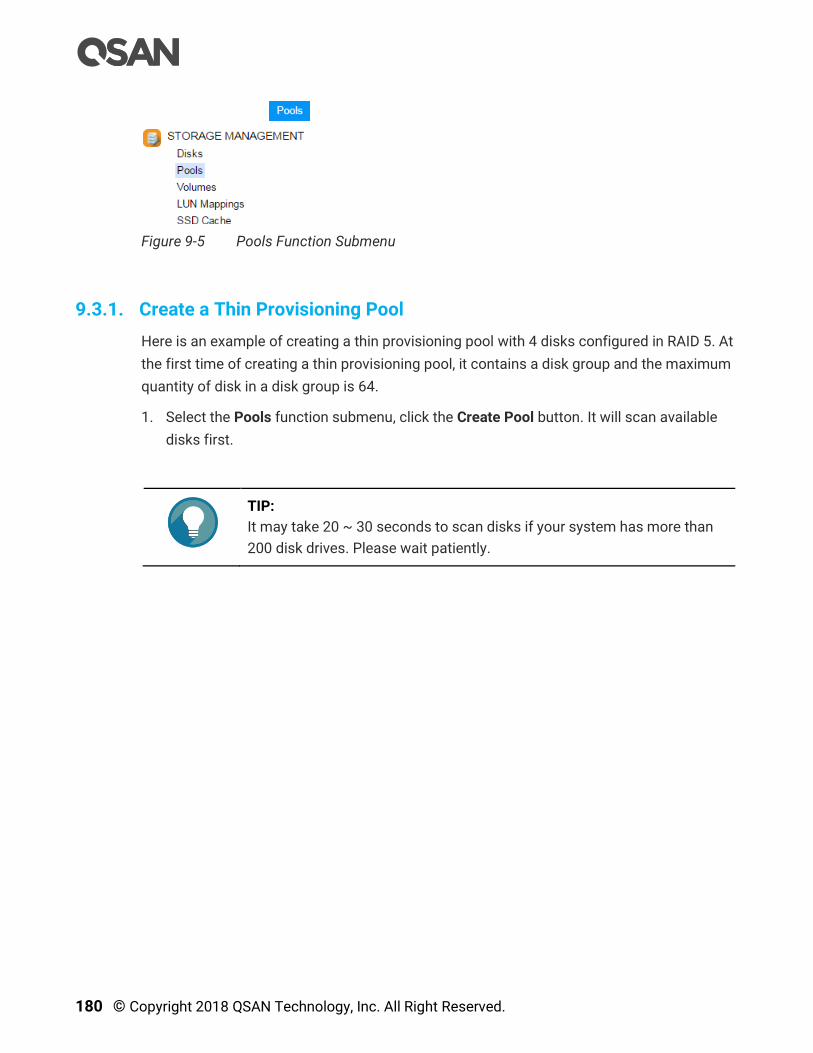
180 © Copyright 2018 QSAN Technology, Inc. All Right Reserved.
Figure 9-5 Pools Function Submenu
9.3.1. Create a Thin Provisioning Pool
Here is an example of creating a thin provisioning pool with 4 disks configured in RAID 5. At
the first time of creating a thin provisioning pool, it contains a disk group and the maximum
quantity of disk in a disk group is 64.
1. Select the Pools function submenu, click the Create Pool button. It will scan available
disks first.
TIP:
It may take 20 ~ 30 seconds to scan disks if your system has more than
200 disk drives. Please wait patiently.

Thin Provisioning 181
Figure 9-6 Create a Thin Provisioning Pool Step 1
2. Select the Pool Type as Thin Provisioning.
3. Enter a Pool Name for the pool. The maximum length of the pool name is 16 characters.
Valid characters are [ A~Z | a~z | 0~9 | -_<> ].
4. Select a Preferred Controller from the drop-down list. The backend I/O resources in this
pool will be processed by the preferred controller which you specified. This option is
available when dual controllers are installed.
5. Check the Enable SED Pool checkbox. Enabling SED pool will use the secure SEDs to
create a pool. Intermixing SEDs and non-SEDs are not supported in a pool.
6. Click the Next button to continue.
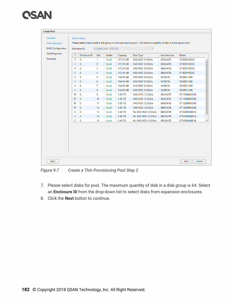
182 © Copyright 2018 QSAN Technology, Inc. All Right Reserved.
Figure 9-7 Create a Thin Provisioning Pool Step 2
7. Please select disks for pool. The maximum quantity of disk in a disk group is 64. Select
an Enclosure ID from the drop-down list to select disks from expansion enclosures.
8. Click the Next button to continue.
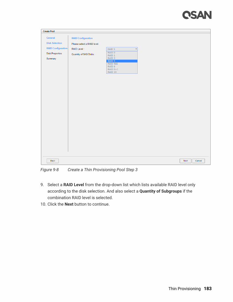
Thin Provisioning 183
Figure 9-8 Create a Thin Provisioning Pool Step 3
9. Select a RAID Level from the drop-down list which lists available RAID level only
according to the disk selection. And also select a Quantity of Subgroups if the
combination RAID level is selected.
10. Click the Next button to continue.
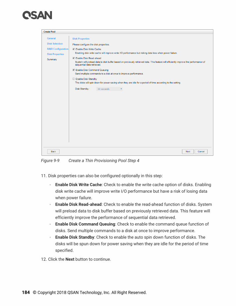
184 © Copyright 2018 QSAN Technology, Inc. All Right Reserved.
Figure 9-9 Create a Thin Provisioning Pool Step 4
11. Disk properties can also be configured optionally in this step:
。 Enable Disk Write Cache: Check to enable the write cache option of disks. Enabling
disk write cache will improve write I/O performance but have a risk of losing data
when power failure.
。 Enable Disk Read-ahead: Check to enable the read-ahead function of disks. System
will preload data to disk buffer based on previously retrieved data. This feature will
efficiently improve the performance of sequential data retrieved.
。 Enable Disk Command Queuing: Check to enable the command queue function of
disks. Send multiple commands to a disk at once to improve performance.
。 Enable Disk Standby: Check to enable the auto spin down function of disks. The
disks will be spun down for power saving when they are idle for the period of time
specified.
12. Click the Next button to continue.
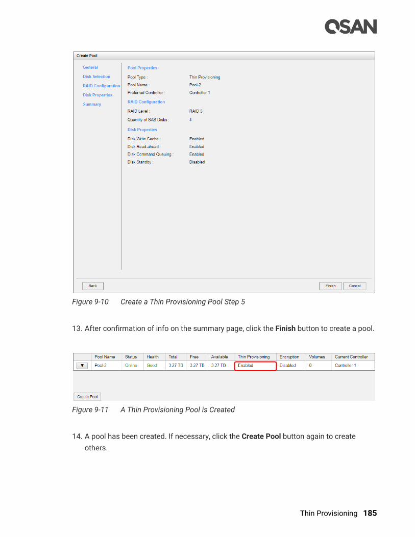
Thin Provisioning 185
Figure 9-10 Create a Thin Provisioning Pool Step 5
13. After confirmation of info on the summary page, click the Finish button to create a pool.
Figure 9-11 A Thin Provisioning Pool is Created
14. A pool has been created. If necessary, click the Create Pool button again to create
others.

186 © Copyright 2018 QSAN Technology, Inc. All Right Reserved.
9.3.2. List Thin Provisioning Pools
Click a pool; it will display the related disk groups. Similarly, click a disk group; it will display
the related disk drives. The pool properties can be configured by clicking the functions
button to the left side of the specific pool.
Figure 9-12 List Thin Provisioning Pools
This table shows the column descriptions.
Table 9-3 Pool Column Descriptions
Column Name Description
Pool Name The pool name.
Status The status of the pool:
Online: The pool is online.
Offline: The pool is offline.
Rebuilding: The pool is being rebuilt.
Migrating: The pool is being migrated.
Relocating: The pool is being relocated.
EE Rebuilding: The pool is being RAID EE rebuilt.
Health The health of the pool:
Good: The pool is good.
Failed: The pool is failed.
Degraded: The pool is not healthy and not completed. The reason
could be lack of disk(s) or have failed disk.
Total Total capacity of the pool.

Thin Provisioning 187
Free Free capacity of the pool.
Available Available capacity of the pool.
Thin
Provisioning
The status of Thin provisioning:
Disabled.
Enabled.
Encryption The Data Secure Mode:
Disabled: The pool is not encrypted.
Enabled: The pool is encrypted.
Volumes The quantity of volumes in the pool.
Current
Controller
(This option is
only visible when
dual controllers
are installed.)
The current running controller of the pool.
Table 9-4 Disk Group Column Descriptions
Column Name Description
No. The number of the disk group.
Status The status of the disk group:
Online: The disk group is online.
Offline: The disk group is offline.
Rebuilding: The disk group is being rebuilt.
Migrating: The disk group is being migrated.
Relocating: The disk group is being relocated.
EE Rebuilding: The disk group is being RAID EE rebuilt.
Health The health of the disk group:
Good: The disk group is good.
Failed: The disk group fails.
Degraded: The pool is not healthy and not complete. The reason
could be missing or failed disks.
Total Total capacity of the disk group.
Free Free capacity of the disk group.
RAID The RAID level of the disk group.
Disks Used The quantity of disk drives in the disk group.
RAID EE Spare The quantity of RAID EE spare disk drives in the disk group. Display
N/A is the RAID level is traditional.

188 © Copyright 2018 QSAN Technology, Inc. All Right Reserved.
Table 9-5 Disk Column Descriptions
Column Name Description
Enclosure ID The enclosure ID.
Slot The position of the disk drive.
Status The status of the disk drive:
Online: The disk drive is online.
Missing: The disk drive is missing in the pool.
Rebuilding: The disk drive is being rebuilt.
Transitioning: The disk drive is being migrated or is replaced by
another disk when rebuilding occurs.
Scrubbing: The disk drive is being scrubbed.
Check Done: The disk drive has been checked the disk health.
Copying Back: The disk drive is being copied back.
Health The health of the disk drive:
Good: The disk drive is good.
Failed: The disk drive is failed.
Error Alert: S.M.A.R.T. error alerts.
Read Errors: The disk drive has unrecoverable read errors.
Capacity The capacity of the disk drive.
Disk Type The type of the disk drive:
[ SAS HDD | NL-SAS HDD | SAS SSD | SATA SSD ]
[ 12.0Gb/s | 6.0Gb/s | 3.0Gb/s | 1.5Gb/s ]
Manufacturer The manufacturer of the disk drive.
Model The model name of disk drive.
9.3.3. Operations on Thin Provisioning Pools
Most operations are described in the Configuring Storage Pools section. For more
information, please refer to the chapter 8.4.3, Operations on Thick Provisioning Pools
section. We describe the operations about thin provisioning in the following.
Change Thin Provisioning Policy of the Pool
Click ▼ -> Change Thin Provisioning Policy in pools to change the policies of the thin
provisioning pool. There are 6 levels of threshold percentage and the default values defined.
The event log levels and actions can be changed when the usage of the pool capacity
reaches the threshold. For more information, please refer to the chapter 9.2.3, Thin
Provisioning Policies section
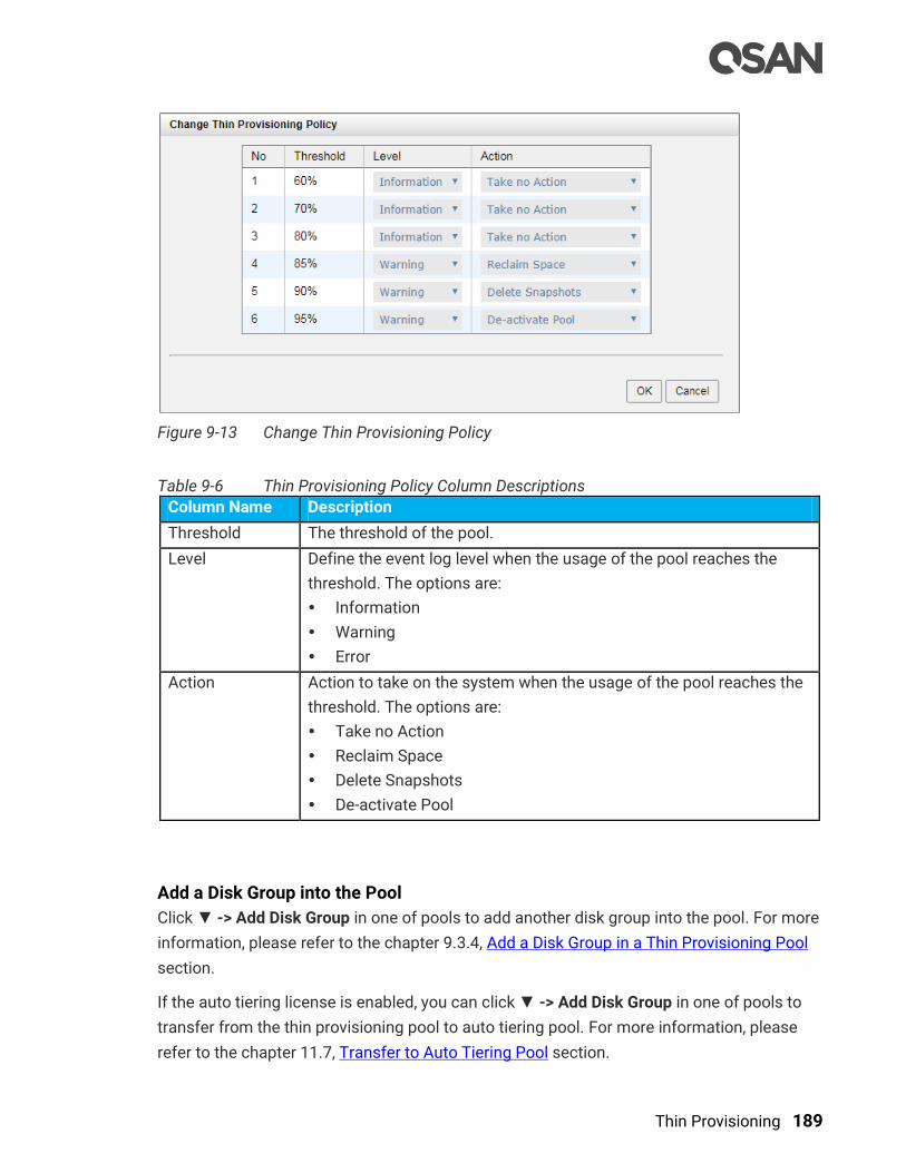
Thin Provisioning 189
Figure 9-13 Change Thin Provisioning Policy
Table 9-6 Thin Provisioning Policy Column Descriptions
Column Name Description
Threshold The threshold of the pool.
Level Define the event log level when the usage of the pool reaches the
threshold. The options are:
Information
Warning
Error
Action Action to take on the system when the usage of the pool reaches the
threshold. The options are:
Take no Action
Reclaim Space
Delete Snapshots
De-activate Pool
Add a Disk Group into the Pool
Click ▼ -> Add Disk Group in one of pools to add another disk group into the pool. For more
information, please refer to the chapter 9.3.4, Add a Disk Group in a Thin Provisioning Pool
section.
If the auto tiering license is enabled, you can click ▼ -> Add Disk Group in one of pools to
transfer from the thin provisioning pool to auto tiering pool. For more information, please
refer to the chapter 11.7, Transfer to Auto Tiering Pool section.

190 © Copyright 2018 QSAN Technology, Inc. All Right Reserved.
Figure 9-14 Transfer Thin Provisioning Pool to Auto Tiering
CAUTION:
The action of transferring from the thin provisioning pool to auto tiering is
irreversible. Carefully consider the consequences before making this
change.
Move Disk Group Member Disks
Click ▼ -> Move Disk Group in disk group to move the member disks of disk group to other
disk drives. Select disks and then click the OK button.
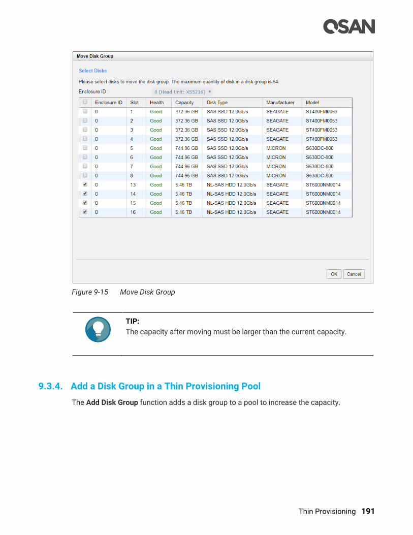
Thin Provisioning 191
Figure 9-15 Move Disk Group
TIP:
The capacity after moving must be larger than the current capacity.
9.3.4. Add a Disk Group in a Thin Provisioning Pool
The Add Disk Group function adds a disk group to a pool to increase the capacity.

192 © Copyright 2018 QSAN Technology, Inc. All Right Reserved.
Figure 9-16 Add a Disk Group in a Thin Provisioning Pool
Here is an example of adding a disk group into a thin provisioning pool with 2 disks
configured in RAID 1.
1. Select a pool, click ▼ -> Add Disk Group to add a disk group in a thin provisioning pool.
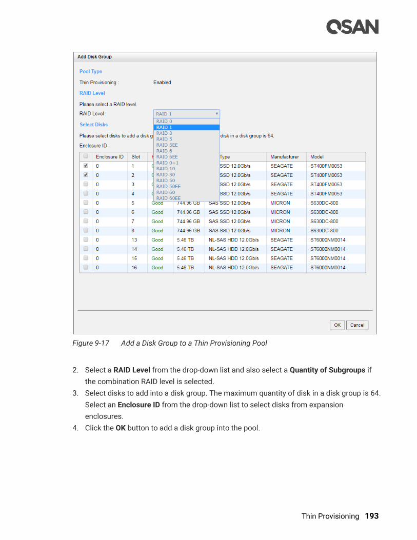
Thin Provisioning 193
Figure 9-17 Add a Disk Group to a Thin Provisioning Pool
2. Select a RAID Level from the drop-down list and also select a Quantity of Subgroups if
the combination RAID level is selected.
3. Select disks to add into a disk group. The maximum quantity of disk in a disk group is 64.
Select an Enclosure ID from the drop-down list to select disks from expansion
enclosures.
4. Click the OK button to add a disk group into the pool.

194 © Copyright 2018 QSAN Technology, Inc. All Right Reserved.
Figure 9-18 A Disk Group is Added
5. A disk group has been added into the pool.
TIP:
If auto tiering license is enabled, the thin provisioning pool without disk
group of mixed disk type can be transferred to the auto tiering pool by
Add Disk Group option. Please refer to the chapter 11.6.2, Transfer from
Thin Provisioning Pool to Auto Tiering section.
9.4. Configure Volumes
This section will describe the operations of configuring volume in a thin provisioning pool.
9.4.1. Create a Volume in a Thin Provisioning Pool
Here is an example of creating a volume of thin provisioning pool.
1. Select the Volumes function submenu, click the Create Volume button.

Thin Provisioning 195
Figure 9-19 Create a Volume in Thin Provisioning Pool Step 1
2. Enter a Volume Name for the pool. The maximum length of the volume name is 32
characters. Valid characters are [ A~Z | a~z | 0~9 | -_<> ].
3. Select a Pool Name from the drop-down list. It will also display the available capacity of
the pool.
4. Enter required Capacity. The unit can be selected from the drop-down list.
5. Select Volume Type. The options are RAID Volume (for general RAID usage) and
Backup Volume (for the target volume of local clone or remote replication).
6. Click the Next button to continue.
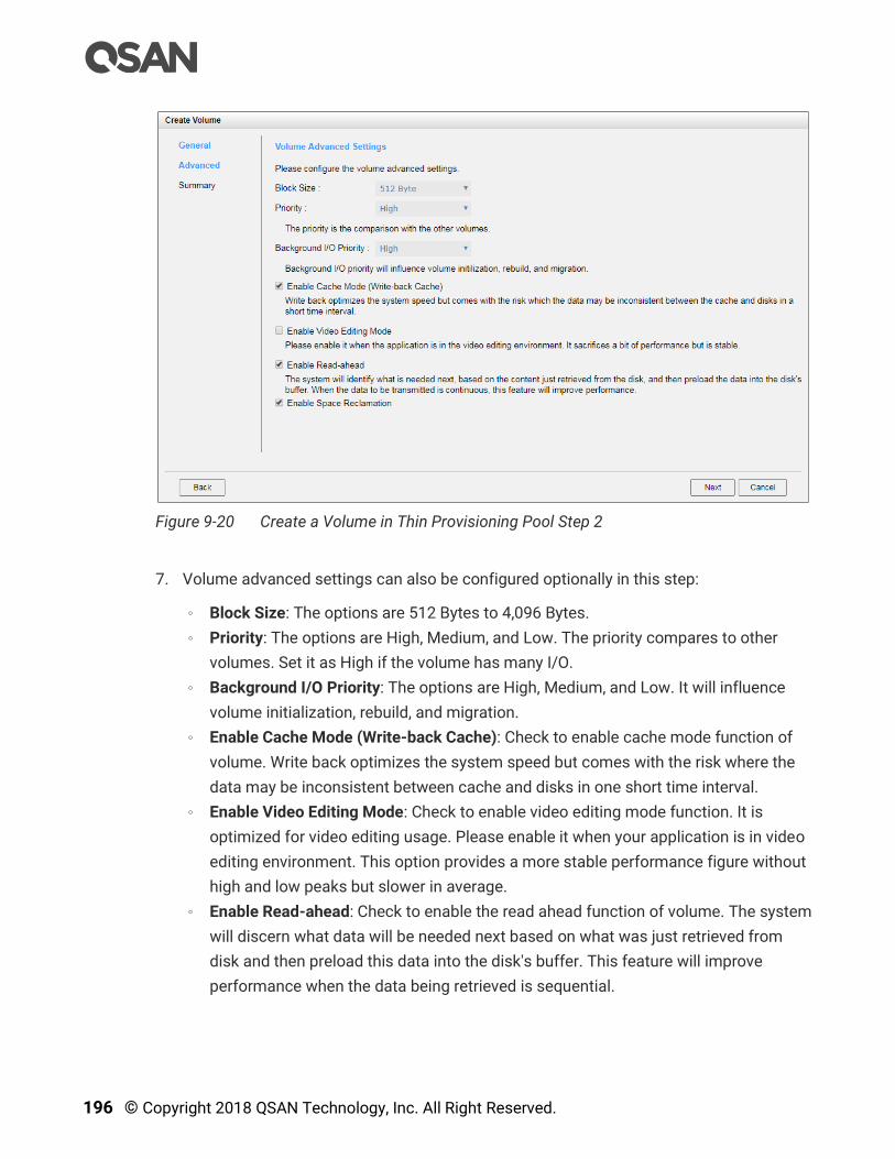
196 © Copyright 2018 QSAN Technology, Inc. All Right Reserved.
Figure 9-20 Create a Volume in Thin Provisioning Pool Step 2
7. Volume advanced settings can also be configured optionally in this step:
。 Block Size: The options are 512 Bytes to 4,096 Bytes.
。 Priority: The options are High, Medium, and Low. The priority compares to other
volumes. Set it as High if the volume has many I/O.
。 Background I/O Priority: The options are High, Medium, and Low. It will influence
volume initialization, rebuild, and migration.
。 Enable Cache Mode (Write-back Cache): Check to enable cache mode function of
volume. Write back optimizes the system speed but comes with the risk where the
data may be inconsistent between cache and disks in one short time interval.
。 Enable Video Editing Mode: Check to enable video editing mode function. It is
optimized for video editing usage. Please enable it when your application is in video
editing environment. This option provides a more stable performance figure without
high and low peaks but slower in average.
。 Enable Read-ahead: Check to enable the read ahead function of volume. The system
will discern what data will be needed next based on what was just retrieved from
disk and then preload this data into the disk's buffer. This feature will improve
performance when the data being retrieved is sequential.

Thin Provisioning 197
。 Enable Space Reclamation: Check to enable the space reclamation function of the
volume when the pool is thin provisioning. For more information about space
reclamation, please refer to the chapter 9.2.2, Space Reclamation section.
8. Click the Next button to continue.
Figure 9-21 Create a Volume in Thin Provisioning Pool Step 3
9. After confirmation at summary page, click the Finish button to create a volume.
10. The volume has been created. It will be initialized in protection RAID level (e.g., RAID 1, 3,
5, 6, 0+1, 10, 30, 50, and 60).
Figure 9-22 A Volume in Thin Provisioning Pool is Created

198 © Copyright 2018 QSAN Technology, Inc. All Right Reserved.
11. A volume has been created. If necessary, click the Create Volume button again to create
others.
TIP:
SANOS supports instant RAID volume availability. The volume can be
used immediately when it is initializing or rebuilding.
TIP:
If the pool contains some disk drives of 4Kn type, it is not available to set
512, 1024, or 2048 block size. When the case happens, it will pop up a
warning message and suggest changing the block size to 4096.
9.4.2. List Volumes and Operations on Volumes
Most operations are described in the chapter 8.5, Configuring Volumes section. For more
information about list volume, please refer to the chapter 8.5.2, List Volumes section. For
more information about operations on volumes, please refer to the chapter 8.5.3, Operations
on Volumes section. We describe the operations about thin provisioning in the following.
Change Volume Properties
Click ▼ -> Change Volume Properties to change the volume properties of the volume.
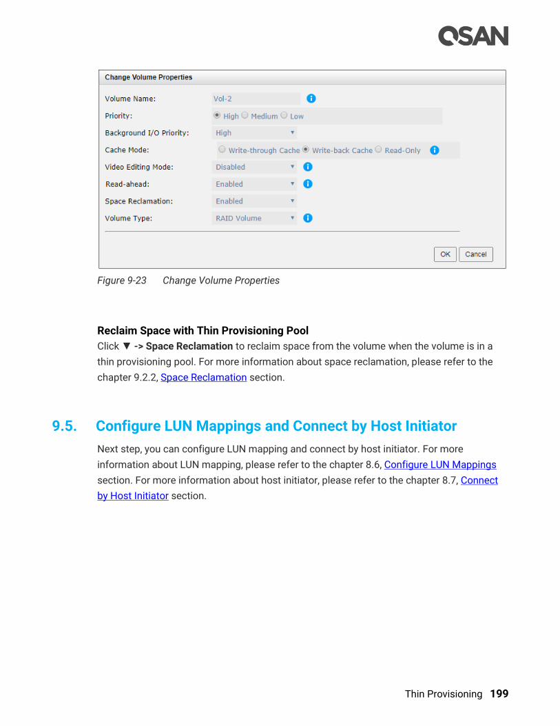
Thin Provisioning 199
Figure 9-23 Change Volume Properties
Reclaim Space with Thin Provisioning Pool
Click ▼ -> Space Reclamation to reclaim space from the volume when the volume is in a
thin provisioning pool. For more information about space reclamation, please refer to the
chapter 9.2.2, Space Reclamation section.
9.5. Configure LUN Mappings and Connect by Host Initiator
Next step, you can configure LUN mapping and connect by host initiator. For more
information about LUN mapping, please refer to the chapter 8.6, Configure LUN Mappings
section. For more information about host initiator, please refer to the chapter 8.7, Connect
by Host Initiator section.
200 © Copyright 2018 QSAN Technology, Inc. All Right Reserved.
10. SSD Cache
This chapter describes an overview and operations of SSD cache. Now we provide two
cache types, SSD read cache and read-write cache.
INFORMATION:
SSD cache 2.0 with read and write cache is available in SANOS firmware
1.1.0.
10.1. Overview
Traditionally, data has been stored on traditional rotating memory, or HDDs (Hard Disk
Drives) and SSDs (Solid-State Drives) are mainly used for mission-critical applications that
demand high-speed storage systems, however tend to be costly. In recent years, the
capacity of HDDs has increased, but their random I/O (Input / Output) has not kept pace. For
some applications such as web commerce, clouds, and virtualization that require both high
capacity and performance, HDDs, though capacious, simply are not fast enough and SSDs
have increased capacity and have declined in cost, making them more attractive for caching
in SAN storage networks.
Smart Response Technology (also known as SSD cache technology) leverages the
strengths of both HDDs and SSDs, to cost-effectively meet the capacity and performance
requirements of enterprise applications. Data is primarily stored on HDDs while SSDs serve
as an extended HDD memory cache for many I/O operations. One of the major benefits of
using SSD cache is the improved application performance, especially for workloads with
frequent I/O activity. The read data of an application that is frequently accessed is copied to
the SSD cache; the write data is stored to the SSD cache temporary and then flush to HDDs
in bulk. So the application receives an immediate performance boost. QSAN SSD cache
enables applications to deliver consistent performance by absorbing bursts of read/write
loads at SSD speeds.
Another important benefit is improved TCO (Total Cost of Ownership) of the system. SSD
cache copies the hot or frequency of data to SSDs in chunks. By offloading many if not most
of the remaining IOPS after SSD cache, the user can fill the remainder of their storage needs
with low cost, high capacity HDDs. This ratio of a small amount of SSD paired with a lot of
HDD offers the best performance at the lowest cost with optimal power efficiency.
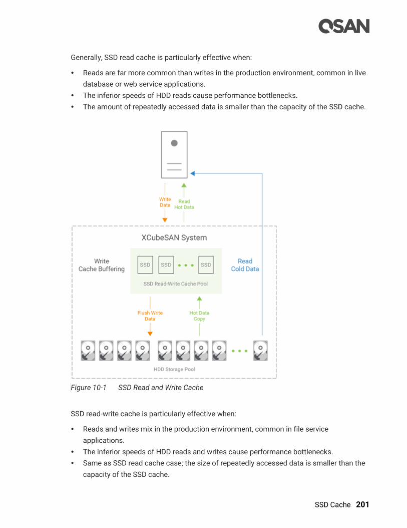
SSD Cache 201
Generally, SSD read cache is particularly effective when:
Reads are far more common than writes in the production environment, common in live
database or web service applications.
The inferior speeds of HDD reads cause performance bottlenecks.
The amount of repeatedly accessed data is smaller than the capacity of the SSD cache.
Figure 10-1 SSD Read and Write Cache
SSD read-write cache is particularly effective when:
Reads and writes mix in the production environment, common in file service
applications.
The inferior speeds of HDD reads and writes cause performance bottlenecks.
Same as SSD read cache case; the size of repeatedly accessed data is smaller than the
capacity of the SSD cache.
202 © Copyright 2018 QSAN Technology, Inc. All Right Reserved.
Willing to take a little risk to increase write performance because it’s write cache
buffering at SSD cache pool. Of course, these write data in SSD cache can be used at
the next read.
10.2. Theory of Operation
SSD cache allows an SSD to function as read cache or write buffer for a HDD volume. In
SSD read cache, it is a secondary cache that improves performance by keeping frequently
accessed data on SSDs where they are read far more quickly than from the HDD volume.
When reads or writes are performed, the data from the HDDs are copied into the SSD cache.
Although the data is duplicated to SSD cache pool, it does not matter if the read cache pool
is corrupted.
In SSD write cache, SSDs are a write buffering storage that improves performance by
storing the write data in SSDs temporary where they are write far more quickly than to the
HDD volume. And then the write data will be flushed to the HDD volume at the appropriate
time. It may take risk of losing data during the period that the write data is stored in SSD
cache if the SSD cache pool is corrupted. The write data has not yet written back to the HDD
volume. So the read-write cache pool needs data protection to protect the write data.
CAUTION:
Using SSD read-write cache may take risk of losing data if the SSD cache
pool is corrupted. User has to monitor the health of the SSD cache pool
carefully.
10.2.1. System Memory and SSD Cache Capacity
SSD cache function needs system memory to store metadata. The usable capacity of SSD
cache is in proportion to the size of the controller system memory. The following table is the
relationship between the system memory per controller and the maximum SSD cache
capacity.

SSD Cache 203
Table 10-1 The Relationship between System Memory and SSD Cache Capacity
System Memory per Controller Maximum SSD Cache Capacity per System
4GB X (Not Support)
8GB ~ 15GB 2TB
16GB ~ 31GB 4TB
32GB ~ 63GB 8TB
64GB ~ 127GB 16TB
128GB 32TB
CAUTION:
SSD cache function is not supported when the system memory is under
8GB per controller.
10.2.2. SSD Cache Pool Architecture
A SSD cache pool is grouped to provide capacity for SSD cache usage of a dedicated
storage pool. The maximum SSD cache pool quantity per system (either dual controller or
single controller) is 4. The following is the storage architecture of SSD cache pool.
Figure 10-2 Storage Architecture of SSD Cache Pool
Take an example of SSD read cache; one or more SSDs with NRAID+ (which is described in
the next section) are grouped into the “SSD Cache Pool 1” and assigned to the “Pool 1” for
use. The maximum SSD quantity in an SSD cache pool is 8. When the SSD read cache is
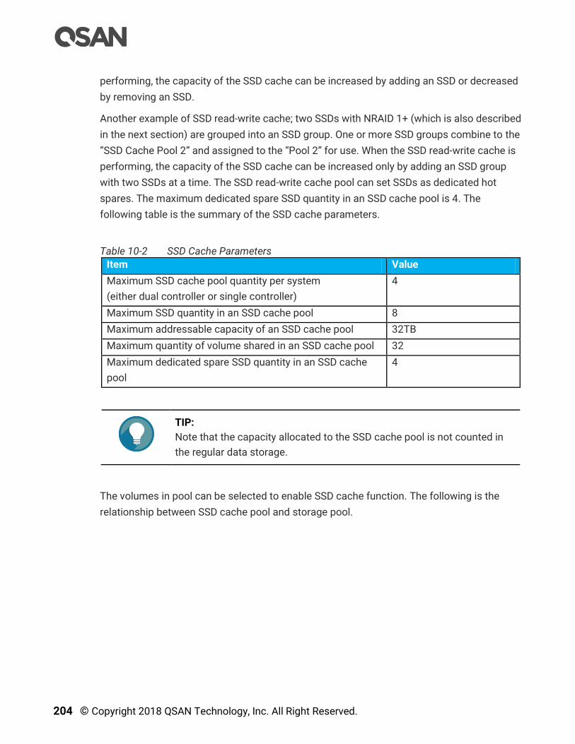
204 © Copyright 2018 QSAN Technology, Inc. All Right Reserved.
performing, the capacity of the SSD cache can be increased by adding an SSD or decreased
by removing an SSD.
Another example of SSD read-write cache; two SSDs with NRAID 1+ (which is also described
in the next section) are grouped into an SSD group. One or more SSD groups combine to the
“SSD Cache Pool 2” and assigned to the “Pool 2” for use. When the SSD read-write cache is
performing, the capacity of the SSD cache can be increased only by adding an SSD group
with two SSDs at a time. The SSD read-write cache pool can set SSDs as dedicated hot
spares. The maximum dedicated spare SSD quantity in an SSD cache pool is 4. The
following table is the summary of the SSD cache parameters.
Table 10-2 SSD Cache Parameters
Item Value
Maximum SSD cache pool quantity per system
(either dual controller or single controller)
4
Maximum SSD quantity in an SSD cache pool 8
Maximum addressable capacity of an SSD cache pool 32TB
Maximum quantity of volume shared in an SSD cache pool 32
Maximum dedicated spare SSD quantity in an SSD cache
pool
4
TIP:
Note that the capacity allocated to the SSD cache pool is not counted in
the regular data storage.
The volumes in pool can be selected to enable SSD cache function. The following is the
relationship between SSD cache pool and storage pool.

SSD Cache 205
Figure 10-3 The Relationship between SSD Cache Pool and Storage Pool
The volumes enabled SSD cache with hot data will consume the capacity of the SSD cache
pool. Users have to consider which volumes are enabled according to the SSD cache
resources. When the SSD cache is performing, you can enable or disable the volume. The
maximum quantity of volume shared in an SSD cache pool is 32.
10.2.3. RAID Level of SSD Cache Pool
SSD read cache with NRAID+
Generally, SSD read cache uses NRAID (Non-RAID) or RAID 0 without data protection to
create the SSD cache storage space. Our SSD read cache technology uses NRAID+ which is
parallel NRAID without striping.
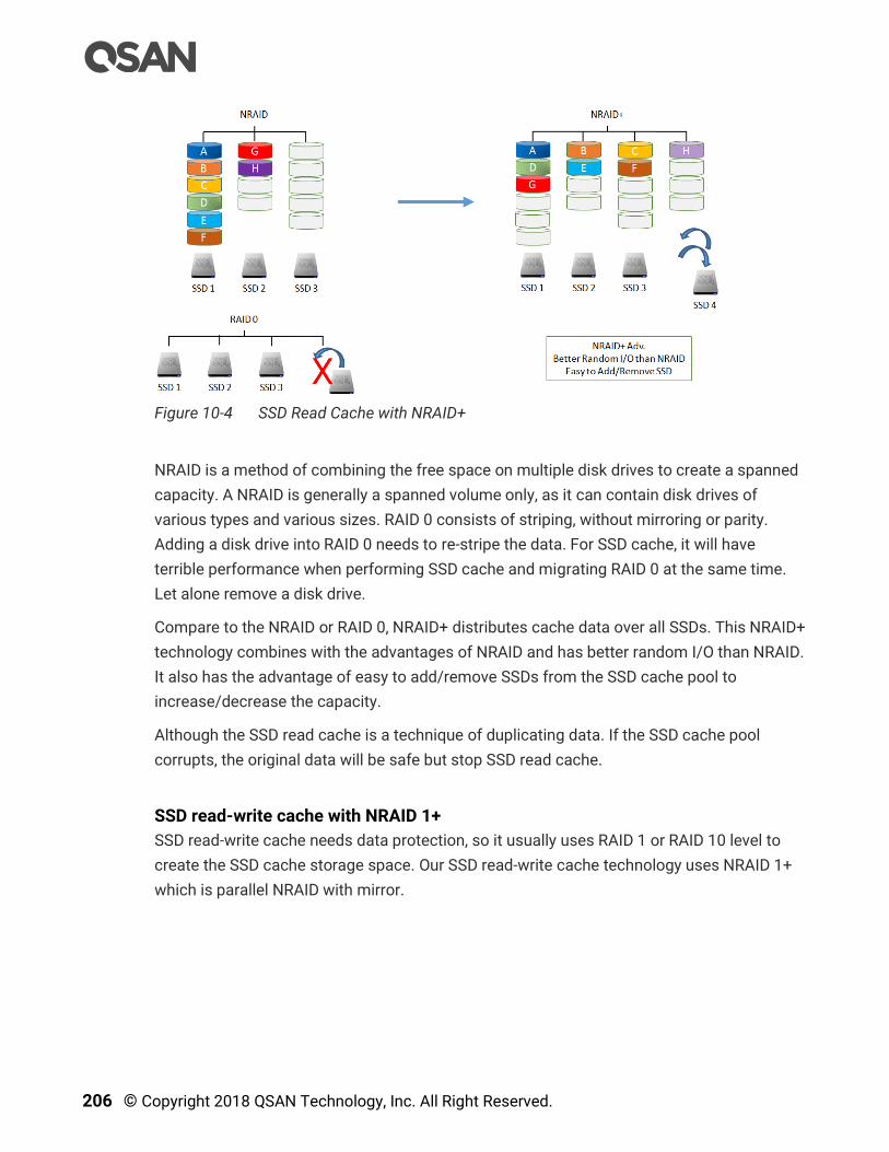
206 © Copyright 2018 QSAN Technology, Inc. All Right Reserved.
Figure 10-4 SSD Read Cache with NRAID+
NRAID is a method of combining the free space on multiple disk drives to create a spanned
capacity. A NRAID is generally a spanned volume only, as it can contain disk drives of
various types and various sizes. RAID 0 consists of striping, without mirroring or parity.
Adding a disk drive into RAID 0 needs to re-stripe the data. For SSD cache, it will have
terrible performance when performing SSD cache and migrating RAID 0 at the same time.
Let alone remove a disk drive.
Compare to the NRAID or RAID 0, NRAID+ distributes cache data over all SSDs. This NRAID+
technology combines with the advantages of NRAID and has better random I/O than NRAID.
It also has the advantage of easy to add/remove SSDs from the SSD cache pool to
increase/decrease the capacity.
Although the SSD read cache is a technique of duplicating data. If the SSD cache pool
corrupts, the original data will be safe but stop SSD read cache.
SSD read-write cache with NRAID 1+
SSD read-write cache needs data protection, so it usually uses RAID 1 or RAID 10 level to
create the SSD cache storage space. Our SSD read-write cache technology uses NRAID 1+
which is parallel NRAID with mirror.
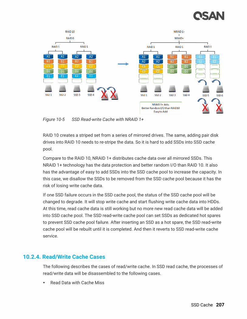
SSD Cache 207
Figure 10-5 SSD Read-write Cache with NRAID 1+
RAID 10 creates a striped set from a series of mirrored drives. The same, adding pair disk
drives into RAID 10 needs to re-stripe the data. So it is hard to add SSDs into SSD cache
pool.
Compare to the RAID 10, NRAID 1+ distributes cache data over all mirrored SSDs. This
NRAID 1+ technology has the data protection and better random I/O than RAID 10. It also
has the advantage of easy to add SSDs into the SSD cache pool to increase the capacity. In
this case, we disallow the SSDs to be removed from the SSD cache pool because it has the
risk of losing write cache data.
If one SSD failure occurs in the SSD cache pool, the status of the SSD cache pool will be
changed to degrade. It will stop write cache and start flushing write cache data into HDDs.
At this time, read cache data is still working but no more new read cache data will be added
into SSD cache pool. The SSD read-write cache pool can set SSDs as dedicated hot spares
to prevent SSD cache pool failure. After inserting an SSD as a hot spare, the SSD read-write
cache pool will be rebuilt until it is completed. And then it reverts to SSD read-write cache
service.
10.2.4. Read/Write Cache Cases
The following describes the cases of read/write cache. In SSD read cache, the processes of
read/write data will be disassembled to the following cases.
Read Data with Cache Miss
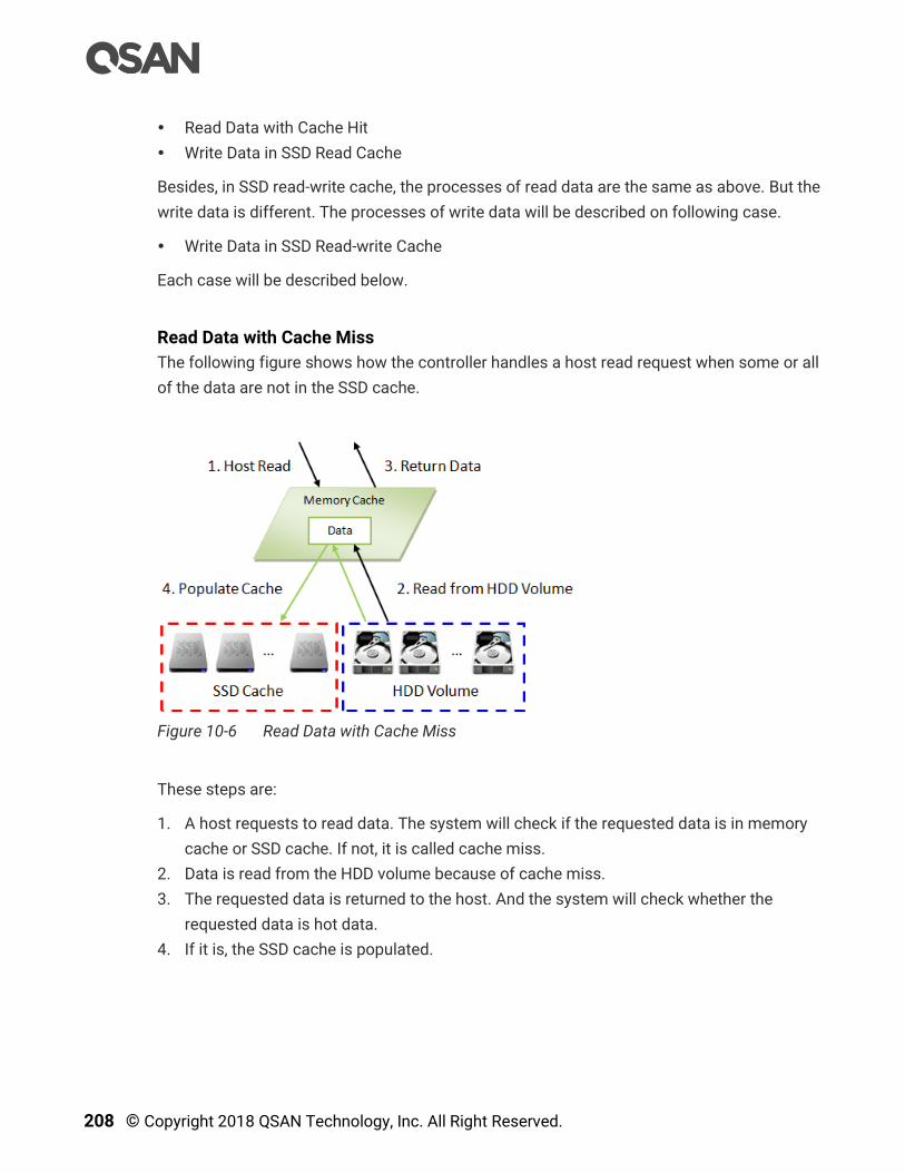
208 © Copyright 2018 QSAN Technology, Inc. All Right Reserved.
Read Data with Cache Hit
Write Data in SSD Read Cache
Besides, in SSD read-write cache, the processes of read data are the same as above. But the
write data is different. The processes of write data will be described on following case.
Write Data in SSD Read-write Cache
Each case will be described below.
Read Data with Cache Miss
The following figure shows how the controller handles a host read request when some or all
of the data are not in the SSD cache.
Figure 10-6 Read Data with Cache Miss
These steps are:
1. A host requests to read data. The system will check if the requested data is in memory
cache or SSD cache. If not, it is called cache miss.
2. Data is read from the HDD volume because of cache miss.
3. The requested data is returned to the host. And the system will check whether the
requested data is hot data.
4. If it is, the SSD cache is populated.

SSD Cache 209
INFORMATION:
The actions that read data from the HDD and then write to the SSD are
called populating the cache. For more information, please refer to the
chapter 10.2.5, Populating the Cache in the next section.
Read Data with Cache Hit
The following figure shows how the controller handles a host read request when the data is
in the SSD cache.
Figure 10-7 Read Data with Cache Hit
These steps are:
1. A host requests a read data. The system finds that the data is in SSD cache, so it is
called cache hit.
2. Data is read from the SSD cache.
3. The requested data is returned to the host.
4. If there is an SSD cache error, data is read from the HDD volume.
Write Data in SSD Read Cache
The following figure shows how the controller handles a host write request in SSD read
cache. The write data can also be frequently accessed data and populated into SSD cache
for next read.

210 © Copyright 2018 QSAN Technology, Inc. All Right Reserved.
Figure 10-8 Write Data in SSD Read Cache
These steps are:
1. A host requests to write data.
2. Data is written to the HDD volume.
3. The status is returned to the host.
4. The SSD cache is populated if the write threshold is reached.
Write Data in SSD Read-write Cache
The following figure shows how the controller handles a host write request in SSD read-
write cache. The write data stays in the SSD cache for a while, and will be flushed to the
HDD volume at the appropriate time.
Figure 10-9 Write Data in SSD Read-write Cache
SSD Cache 211
These steps are:
1. A host requests to write data.
2. Data is written to the SSD cache.
3. The status is returned to the host.
4. Data will be flushed to the HDD volume at the appropriate time.
Flush Write Data to HDD Volume
In SSD read-write cache, the write data will be flushed to the HDD volume in the following
situations.
Flush data to the HDD volumes before the SSD cache pool is deleted.
Flush data to the HDD volumes before the related volume is disabled.
Flush data when the system is idle.
CAUTION:
It will take times to flush data from SSD cache to HDD volumes. Please do
not remove SSDs before complete flushing; otherwise it may take risk of
losing data.
In addition, to avoid taking a long time to complete flushing, please make
sure the front I/O traffic is not heavy when deleting SSD cache pool.
TIP:
It won’t flush data to the HDD volumes when system goes shutdown or
reboots.
10.2.5. Populating the Cache
The actions that read data from the HDD and then write to the SSD are called populating the
cache. Typically, this is a background operation that immediately follows a host read or
write operation. As the goal of the cache is to store frequently accessed data, not every I/O
operation should trigger a cache population, but only ones that pass a certain threshold,
implemented as a counter. There are both a populate-on-read threshold, and a populate-on-
write threshold.
212 © Copyright 2018 QSAN Technology, Inc. All Right Reserved.
Populate-on-read Threshold
When the same data block to be read over the threshold, it is called hot data and populated
to the SSD cache. The threshold must be greater than or equal to 1 in SSD read cache or
SSD read-write cache. The value is forbidden to set 0 because of no action in read cache.
The maximum of the threshold is 4. If larger than 4, the frequently accessed data is hard
into SSD cache, so there is no obvious effect.
Populate-on-write Threshold
When the same data block to be written over the threshold, it is called hot data and
populated to the SSD cache. The threshold must be greater than or equal to 0. If it is set to 0,
no action is performed for a write cache. The value must be greater than or equal to 1 in
SSD read-write cache. The value is forbidden to set 0 because of no action in write cache.
The same as above, the maximum of the threshold is 4. If larger than 4, there is no obvious
effect.
Operation Process
Each cache block on a HDD volume has a read and write counter associated. When a host
requests to read data located in that cache block, the read count is increased. If the data is
not found in the cache and the read count is greater than or equal to the populate-on-read
threshold, then a cache-populate operation is performed concurrently with the host read
operation. If a cache hit occurs, the data is immediately returned from the SSD cache and a
populate operation is not performed. If the read count is smaller than the threshold, a
populate operation is not performed.
Write cases are the same scenario as read.
10.2.6. SSD Cache Tuning
The SSD cache can be tuned to maximize its efficiency base on application usage. Cache
block size, populate-on-read threshold and populate-on-write-threshold are the main
parameters.
Cache Block Size
A large cache block suits applications where frequently accessed data is close to each
other, known as a high locality of reference. A large cache block will also fill up the SSD
cache quickly - this is known as the warm-up time. After the cache is warmed up, the
performance would be quite good for applications with high locality of reference. Such as
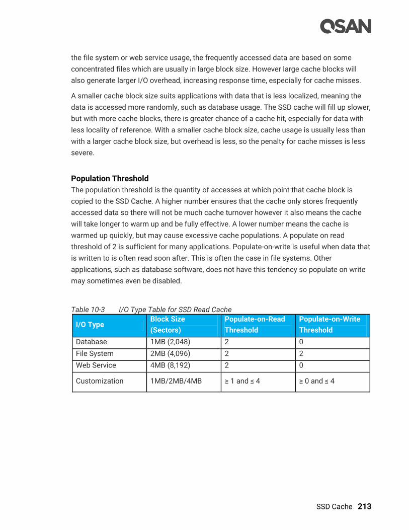
SSD Cache 213
the file system or web service usage, the frequently accessed data are based on some
concentrated files which are usually in large block size. However large cache blocks will
also generate larger I/O overhead, increasing response time, especially for cache misses.
A smaller cache block size suits applications with data that is less localized, meaning the
data is accessed more randomly, such as database usage. The SSD cache will fill up slower,
but with more cache blocks, there is greater chance of a cache hit, especially for data with
less locality of reference. With a smaller cache block size, cache usage is usually less than
with a larger cache block size, but overhead is less, so the penalty for cache misses is less
severe.
Population Threshold
The population threshold is the quantity of accesses at which point that cache block is
copied to the SSD Cache. A higher number ensures that the cache only stores frequently
accessed data so there will not be much cache turnover however it also means the cache
will take longer to warm up and be fully effective. A lower number means the cache is
warmed up quickly, but may cause excessive cache populations. A populate on read
threshold of 2 is sufficient for many applications. Populate-on-write is useful when data that
is written to is often read soon after. This is often the case in file systems. Other
applications, such as database software, does not have this tendency so populate on write
may sometimes even be disabled.
Table 10-3 I/O Type Table for SSD Read Cache
I/O Type Block Size
(Sectors)
Populate-on-Read
Threshold
Populate-on-Write
Threshold
Database 1MB (2,048) 2 0
File System 2MB (4,096) 2 2
Web Service 4MB (8,192) 2 0
Customization 1MB/2MB/4MB ≥ 1 and ≤ 4 ≥ 0 and ≤ 4

214 © Copyright 2018 QSAN Technology, Inc. All Right Reserved.
Table 10-4 I/O Type Table for SSD Read-write Cache
I/O Type Block Size
(Sectors)
Populate-on-Read
Threshold
Populate-on-Write
Threshold
Database 1MB (2,048) 2 1
File System 2MB (4,096) 2 1
Web Service 4MB (8,192) 2 1
Customization 1MB/2MB/4MB ≥ 1 and ≤ 4 ≥ 1 and ≤ 4
As you can see, there are tradeoffs for increasing or decreasing each parameter.
Understanding the data locality of the application is essential and it can be useful to do
some field testing to see what works best.
10.3. Configure SSD Cache
The SSD Cache provides SSD Cache Pools and SSD Cache Statistics function tabs to
configure and monitor SSD cache. This section will describe the operations of configuring
SSD cache.
Figure 10-10 SSD Cache Function Submenu
10.3.1. Enable SSD Cache License
The SSD cache function is optional. Before using it, you have to enable SSD cache license.
Select the Update function tab in the Maintenance function submenu, download Request
License file and send to your local sales to obtain a License Key. After getting the license
key, click the Choose File button to select it, and then click the Apply button to enable. When
the license is enabled, please reboot the system. Each license key is unique and dedicated
to a specific system. If you have already enabled, this option will be invisible.

SSD Cache 215
Figure 10-11 Enable SSD Cache License
10.3.2. Create an SSD Cache Pool
Here is an example of creating an SSD cache pool with 2 SSDs configured in SSD read
cache.
1. Select the SSD Cache function submenu; click the Create SSD Cache Pool button. It will
scan available SSDs first.
Figure 10-12 Create an SSD Cache Pool Step 1
2. Enter an SSD Cache Pool Name for the pool. Maximum length of the pool name is 16
characters. Valid characters are [ A~Z | a~z | 0~9 | -_<> ].

216 © Copyright 2018 QSAN Technology, Inc. All Right Reserved.
3. Select the Cache Type as Read Cache (NRAID+).
4. Select an I/O Type from the drop-down list according to your application.
5. Please select SSDs for SSD cache pool. Maximum quantity of disk is 8. Select an
Enclosure from the drop-down list to select SSDs from expansion enclosures.
6. Click the Next button to continue.
Figure 10-13 Create an SSD Cache Pool Step 2
7. Select a Pool Name from the drop-down list which lists available pools to be assigned to.
8. Within the pool, check Volumes to enable SSD cache, uncheck Volumes to disable.
9. Click the Next button to continue.
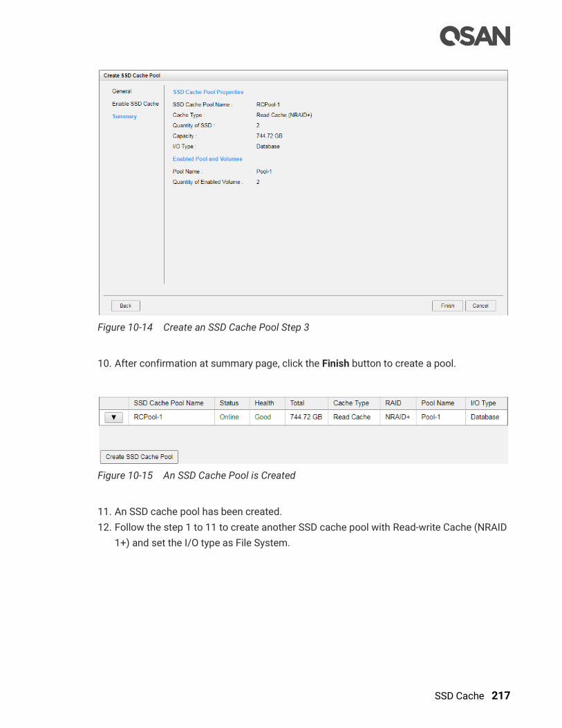
SSD Cache 217
Figure 10-14 Create an SSD Cache Pool Step 3
10. After confirmation at summary page, click the Finish button to create a pool.
Figure 10-15 An SSD Cache Pool is Created
11. An SSD cache pool has been created.
12. Follow the step 1 to 11 to create another SSD cache pool with Read-write Cache (NRAID
1+) and set the I/O type as File System.
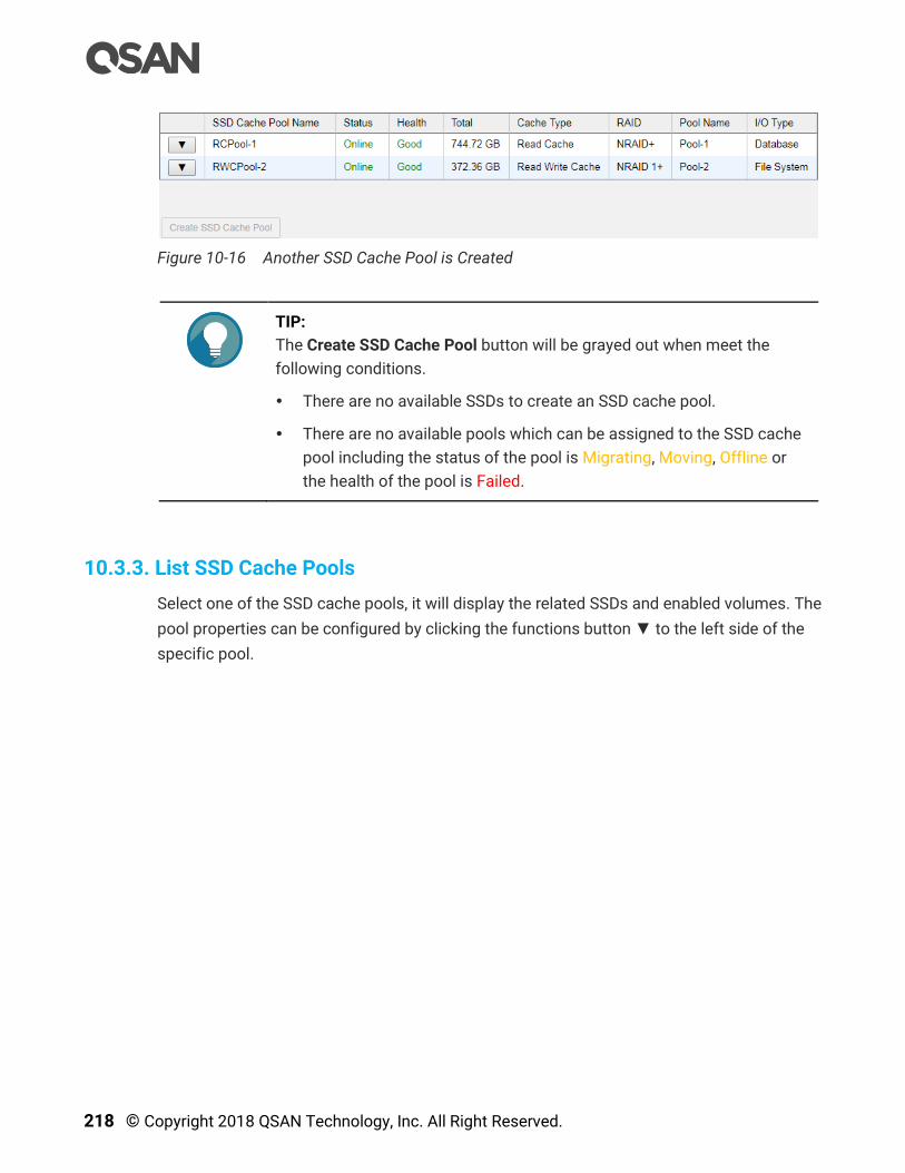
218 © Copyright 2018 QSAN Technology, Inc. All Right Reserved.
Figure 10-16 Another SSD Cache Pool is Created
TIP:
The Create SSD Cache Pool button will be grayed out when meet the
following conditions.
There are no available SSDs to create an SSD cache pool.
There are no available pools which can be assigned to the SSD cache
pool including the status of the pool is Migrating, Moving, Offline or
the health of the pool is Failed.
10.3.3. List SSD Cache Pools
Select one of the SSD cache pools, it will display the related SSDs and enabled volumes. The
pool properties can be configured by clicking the functions button ▼ to the left side of the
specific pool.
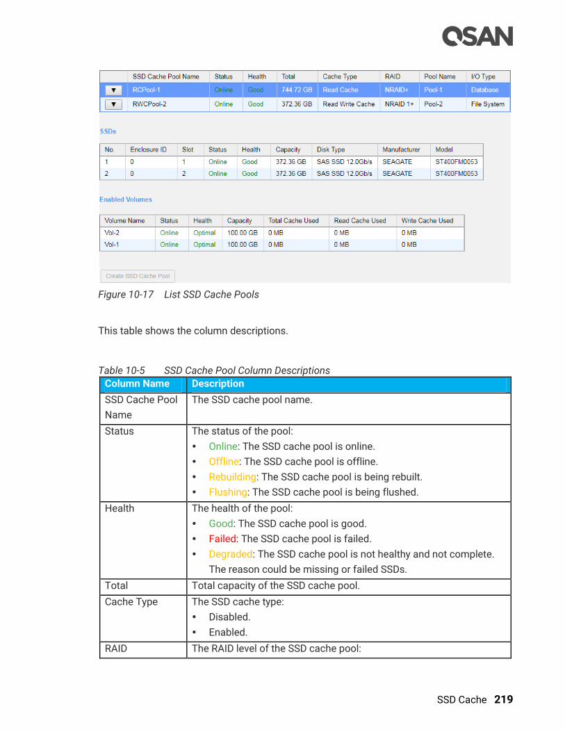
SSD Cache 219
Figure 10-17 List SSD Cache Pools
This table shows the column descriptions.
Table 10-5 SSD Cache Pool Column Descriptions
Column Name Description
SSD Cache Pool
Name
The SSD cache pool name.
Status The status of the pool:
Online: The SSD cache pool is online.
Offline: The SSD cache pool is offline.
Rebuilding: The SSD cache pool is being rebuilt.
Flushing: The SSD cache pool is being flushed.
Health The health of the pool:
Good: The SSD cache pool is good.
Failed: The SSD cache pool is failed.
Degraded: The SSD cache pool is not healthy and not complete.
The reason could be missing or failed SSDs.
Total Total capacity of the SSD cache pool.
Cache Type The SSD cache type:
Disabled.
Enabled.
RAID The RAID level of the SSD cache pool:
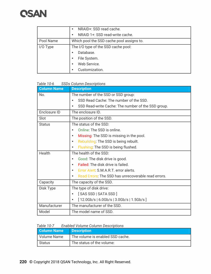
220 © Copyright 2018 QSAN Technology, Inc. All Right Reserved.
NRAID+: SSD read cache.
NRAID 1+: SSD read-write cache.
Pool Name Which pool the SSD cache pool assigns to.
I/O Type The I/O type of the SSD cache pool:
Database.
File System.
Web Service.
Customization.
Table 10-6 SSDs Column Descriptions
Column Name Description
No. The number of the SSD or SSD group:
SSD Read Cache: The number of the SSD.
SSD Read-write Cache: The number of the SSD group.
Enclosure ID The enclosure ID.
Slot The position of the SSD.
Status The status of the SSD:
Online: The SSD is online.
Missing: The SSD is missing in the pool.
Rebuilding: The SSD is being rebuilt.
Flushing: The SSD is being flushed.
Health The health of the SSD:
Good: The disk drive is good.
Failed: The disk drive is failed.
Error Alert: S.M.A.R.T. error alerts.
Read Errors: The SSD has unrecoverable read errors.
Capacity The capacity of the SSD.
Disk Type The type of disk drive:
[ SAS SSD | SATA SSD ]
[ 12.0Gb/s | 6.0Gb/s | 3.0Gb/s | 1.5Gb/s ]
Manufacturer The manufacturer of the SSD.
Model The model name of SSD.
Table 10-7 Enabled Volume Column Descriptions
Column Name Description
Volume Name The volume is enabled SSD cache.
Status The status of the volume:

SSD Cache 221
Online: The volume is online.
Offline: The volume is offline.
Rebuilding: The volume is being rebuilt.
Flushing: The volume is being flushed.
Health The health of the volume:
Optimal: the volume is working well and there is no failed disk in
the RG.
Failed: the pool disk of the volume has single or multiple failed
disks than its RAID level can recover from data loss.
Degraded: At least one disk from the pool of the volume is failed
or plugged out.
Partially optimal: the volume has experienced recoverable read
errors. After passing parity check, the health will become Optimal.
Capacity The capacity of the volume.
Total Cache
Used
The capacity of total cache used.
Write Cache
Used
The capacity of write cache used.
10.3.4. Operations on SSD Cache Pools
The options available in this tab:
Add or Remove SSDs
For an SSD read cache, click ▼ -> Add / Remove SSDs to add into or remove SSDs from the
SSD cache pool. Check SSDs to add into the SSD cache pool, and uncheck SSDs to remove
from the SSD cache pool.
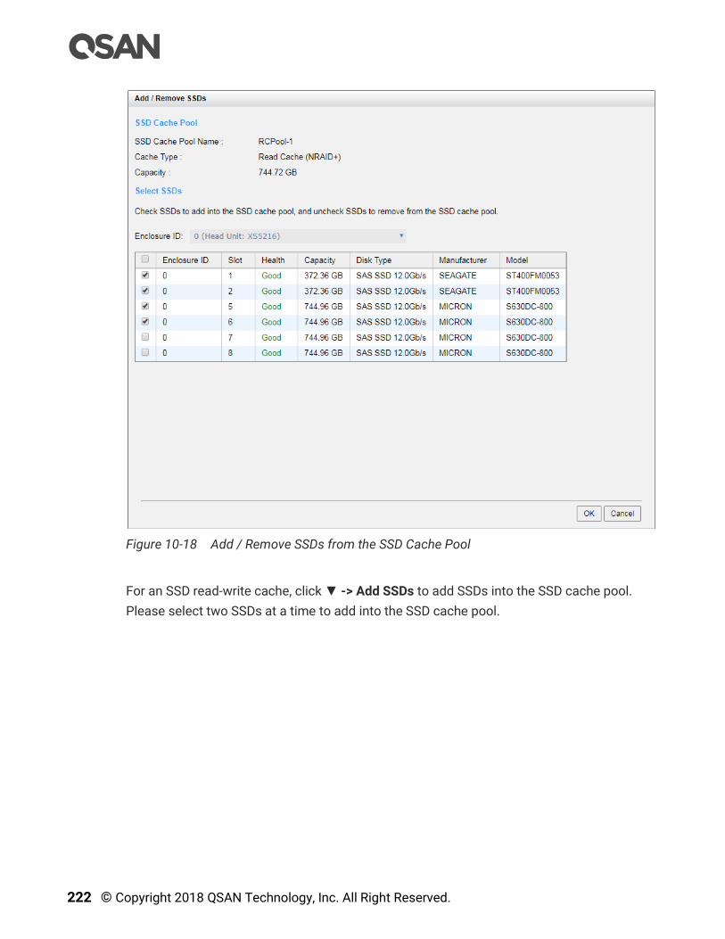
222 © Copyright 2018 QSAN Technology, Inc. All Right Reserved.
Figure 10-18 Add / Remove SSDs from the SSD Cache Pool
For an SSD read-write cache, click ▼ -> Add SSDs to add SSDs into the SSD cache pool.
Please select two SSDs at a time to add into the SSD cache pool.

SSD Cache 223
Figure 10-19 Add SSDs into the SSD Cache Pool
Delete an SSD Cache Pool
Click ▼ -> Delete to delete the SSD cache pool. If deleting an SSD read-write cache pool, it
will take times to flush data from SSDs to HDDs. The SSD cache pool will be deleted after
flushed, otherwise the data may be corrupt.
More Information of the SSD Cache Pool
Click ▼ -> More Information to show the detail information of the SSD cache pool.
10.4. Monitor SSD Cache Statistics
This section will describe the monitoring of SSD cache statistics.
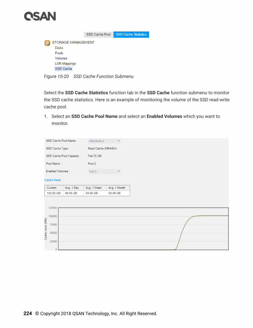
224 © Copyright 2018 QSAN Technology, Inc. All Right Reserved.
Figure 10-20 SSD Cache Function Submenu
Select the SSD Cache Statistics function tab in the SSD Cache function submenu to monitor
the SSD cache statistics. Here is an example of monitoring the volume of the SSD read-write
cache pool.
1. Select an SSD Cache Pool Name and select an Enabled Volumes which you want to
monitor.

SSD Cache 225
Figure 10-21 SSD Cache Statistics
2. The SSD cache statistics include Cache Used, Cache Hits, and Cache Hit Ratio. Each
items have current value, average 1 day value, average 1 week value, and average 1
month value. The diagram displays the current value with 30 seconds refresh and total 4
hours.
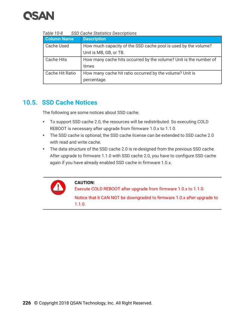
226 © Copyright 2018 QSAN Technology, Inc. All Right Reserved.
Table 10-8 SSD Cache Statistics Descriptions
Column Name Description
Cache Used How much capacity of the SSD cache pool is used by the volume?
Unit is MB, GB, or TB.
Cache Hits How many cache hits occurred by the volume? Unit is the number of
times
Cache Hit Ratio How many cache hit ratio occurred by the volume? Unit is
percentage.
10.5. SSD Cache Notices
The following are some notices about SSD cache.
To support SSD cache 2.0, the resources will be redistributed. So executing COLD
REBOOT is necessary after upgrade from firmware 1.0.x to 1.1.0.
The SSD cache is optional; the SSD cache license can be extended to SSD cache 2.0
with read and write cache.
The data structure of the SSD cache 2.0 is re-designed from the previous SSD cache.
After upgrade to firmware 1.1.0 with SSD cache 2.0, you have to configure SSD cache
again if you have already enabled SSD cache in firmware 1.0.x.
CAUTION:
Execute COLD REBOOT after upgrade from firmware 1.0.x to 1.1.0.
Notice that it CAN NOT be downgraded to firmware 1.0.x after upgrade to
1.1.0.
Auto Tiering 227
11. Auto Tiering
This chapter describes an overview and operations of auto tiering.
INFORMATION:
Auto tiering 2.0 with flexible RAID and disk configurations is available in
SANOS firmware 1.2.0.
11.1. Overview
From the perspective of storage features, the performance of SSD is high, but the cost is
also high per GB. Relatively speaking, the cost of traditional hard drive is low, so as
performance is relatively poor. If we follow the 80/20 rule to configure storage systems, all-
SSD configuration is unreasonable for all but the most intensive applications. In fact, SSD
will be needed in only a small part for most typical applications, regardless of whether or not
a critical application, thus giving SSD resources for general storage needs is hugely cost-
prohibitive. Although traditional hard disk performance is enough for general applications
which I/O requirements are not high, the traditional all-hard-drive configuration is also
gradually been inadequate.
On the other hand, the data itself has a lifecycle. Since the data in the course of its life cycle,
it has experienced different levels of activity. In common usage, when creating the data, it is
usually used. As the age of the data increases, it is accessed less often.
The Solution
Therefore, to balance performance and cost factors, adapting hybrid storage architecture
with a mixture of SSD and traditional HDD seems to be the most reasonable approach for
modern IT environments. Generally, SSD-based storage capacity in 10 to 15% of the total
storage capacity should be enough to fulfill the requirements of critical high I/O applications.
An automated tiering pool is a simple and elegant solution for dynamically matching
storage requirements with changes in the frequency of data access.

228 © Copyright 2018 QSAN Technology, Inc. All Right Reserved.
Figure 11-1 Auto Tiering Pool
11.1.1. Tier Categories
As the name suggestion, auto tiering must have two tiers at least. Automated tiering pool
segregated disk drives into three categories for dual controllers and four for single
controller.
Tier 1: SSD drives for extreme performance tier
Tier 2: SAS drives (15K or 10K RPM SAS HDD) for performance tier
Tier 3: Nearline SAS drives (7.2K or lower RPM SAS HDD) for capacity tier
Tier 4: SATA drives for capacity tier (for single controller only, not recommended)
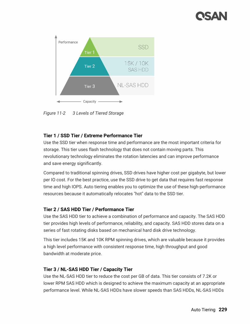
Auto Tiering 229
Figure 11-2 3 Levels of Tiered Storage
Tier 1 / SSD Tier / Extreme Performance Tier
Use the SSD tier when response time and performance are the most important criteria for
storage. This tier uses flash technology that does not contain moving parts. This
revolutionary technology eliminates the rotation latencies and can improve performance
and save energy significantly.
Compared to traditional spinning drives, SSD drives have higher cost per gigabyte, but lower
per IO cost. For the best practice, use the SSD drive to get data that requires fast response
time and high IOPS. Auto tiering enables you to optimize the use of these high-performance
resources because it automatically relocates "hot" data to the SSD tier.
Tier 2 / SAS HDD Tier / Performance Tier
Use the SAS HDD tier to achieve a combination of performance and capacity. The SAS HDD
tier provides high levels of performance, reliability, and capacity. SAS HDD stores data on a
series of fast rotating disks based on mechanical hard disk drive technology.
This tier includes 15K and 10K RPM spinning drives, which are valuable because it provides
a high level performance with consistent response time, high throughput and good
bandwidth at moderate price.
Tier 3 / NL-SAS HDD Tier / Capacity Tier
Use the NL-SAS HDD tier to reduce the cost per GB of data. This tier consists of 7.2K or
lower RPM SAS HDD which is designed to achieve the maximum capacity at an appropriate
performance level. While NL-SAS HDDs have slower speeds than SAS HDDs, NL-SAS HDDs

230 © Copyright 2018 QSAN Technology, Inc. All Right Reserved.
can significantly reduce power consumption and extend capacity in more expensive and
higher performance storage tiers.
In a typical system, most of the application data has very little I/O activity. Because NL-SAS
HDDs cost less per GB, they are the most appropriate media type for the "cold" data. NL-SAS
HDDs consume less power than SAS HDDs and provide total cost of ownership
improvement that take into purchase cost.
11.1.2. Flexible RAID and Disk Configurations
Auto Tiering 2.0 supports flexible RAID and disk configurations. You can create each tier
(disk group) with different RAID level and different quantity of disk. For example, SSD tier
uses 4 disks with RAID 10 for extreme performance, SAS tier uses 6 disks with RAID 6, and
NL-SAS tier uses 8 disks with RAID 5 for capacity. This feature is very important for IT
administrator to arrange storage plan flexibly.
Figure 11-3 Flexible RAID and Disk Configurations
11.2. Theory of Operation
Auto tiering is the automated progression or demotion of data across different tiers (types)
of storage devices and media. The movement of data takes place in an automated way with
the help of software and is assigned to the ideal storage media according to performance
and capacity requirements. It also includes the ability to define rules and policies that
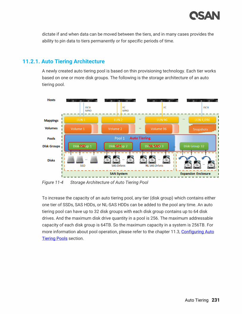
Auto Tiering 231
dictate if and when data can be moved between the tiers, and in many cases provides the
ability to pin data to tiers permanently or for specific periods of time.
11.2.1. Auto Tiering Architecture
A newly created auto tiering pool is based on thin provisioning technology. Each tier works
based on one or more disk groups. The following is the storage architecture of an auto
tiering pool.
Figure 11-4 Storage Architecture of Auto Tiering Pool
To increase the capacity of an auto tiering pool, any tier (disk group) which contains either
one tier of SSDs, SAS HDDs, or NL-SAS HDDs can be added to the pool any time. An auto
tiering pool can have up to 32 disk groups with each disk group contains up to 64 disk
drives. And the maximum disk drive quantity in a pool is 256. The maximum addressable
capacity of each disk group is 64TB. So the maximum capacity in a system is 256TB. For
more information about pool operation, please refer to the chapter 11.3, Configuring Auto
Tiering Pools section.

232 © Copyright 2018 QSAN Technology, Inc. All Right Reserved.
Table 11-1 Auto Tiering Pool Parameters
Item Value
Maximum disk group quantity in a pool 32
Maximum disk drive quantity in a disk group 64
Maximum RAID EE spare quantity in a disk group 8
Maximum disk drive quantity in a pool
(include dedicated spares)
256
Maximum pool quantity per system 64
Maximum dedicated spare quantity in a pool 8
Maximum tiers
(include SSD, SAS HDD, NL-SAS HDD)
3
Maximum addressable capacity of a disk group 64TB
Maximum addressable capacity of an auto tiering pool 256TB
Maximum addressable capacity of total auto tiering pools
(include thin provisioning pools)
1,024TB
Provisioning granularity 1GB
By design, the auto tiering feature allows selecting policies that define how data are moved
between different tiers, and in many cases provides the ability to pin data to tiers
permanently or for specific periods of time.
Auto tiering storage is the assignment of different categories of data to different disk types.
It operates based on relocating the most active data up to the highest available tier and the
least active data down to the lowest tier. Auto tiering works based on an allocation unit
(granularity) of 1GB and relocates data by moving the entire unit to the appropriate tier,
depending on the tiering policy selected for that particular volume.
In order to ensure sufficient space in the higher tiers, 10% of the space is reserved in each
higher tier to prepare for the data allocation for those tiering policies which would allocate
initial space in highest available tiers. By reclaiming this 10% headroom, the least active
units within each tier move to lower tiers. The whole mechanism of auto tiering contains
three steps, statistic collection by accessed counts, ranking hotness data by the statistic
collection, and then relocation data via ranking.
Auto Tiering 233
11.2.2. Intelligent Auto Tiering Mechanism
Auto tiering storage management system manages the data relocation and monitors the
data hotness ratio using half-life coefficient and advanced ranking algorithm. It operates on
three major functions.
Statistics Collection
The volume space is divided into units of equal size in which the hotness is collected and
analyzed per hour. Activity level of a sub LUN is determined by counting the quantity of read
and write access on the sub LUN. Logical volume manager maintains a cumulative I/O
count and weights each I/O by how recently it arrived. The new coming I/O is given a full
weight. After approximately 24 hours, the weight of this IO is nearly cut in half and continues
to decrease. The reduction weight is processing per hour by our precision algorism. This
statistics collection occurs continuously in the background for auto tiering pool.
Ranking
This analysis produces a rank ordering of each sub LUN within the pool. Note that the
policies of volumes would affect how sub LUNs are ranked.
After analysis, the system would generate following information for each tier:
The amount of data to be moved up
The amount of data to be moved down
The amount of data to be moved into a tier.
TIP:
The hotness analysis process which includes statistics collection and
ranking may take minutes to complete.
Relocation
According to the hotness analysis, relocation is processed during the user-defined
relocation window, which is the number of minutes given to the relocation process. When
the window closes, the relocation process would stop relocating data. The other parameter
is relocation rate which controls speed of the relocation process. Valid value of relocation
rate is Fast, Medium, and Slow.
Auto tiering promotes sub LUNs according to the candidate list that it created in the
analysis stage. During relocation, it prioritizes relocating sub LUNs to higher tiers. At the

234 © Copyright 2018 QSAN Technology, Inc. All Right Reserved.
same time, sub LUNs are only relocated to higher tiers if the space they occupy is required
for a higher priority. Using the mechanism, auto tiering makes sure that the higher
performing drives are always used.
During I/O, as data is written to a pool, auto tiering attempts to move it to the higher tiers if
space is available and the tiering policy allows for it. As we describe before, the relocation
process will keep 10% of the free space in all tiers. This space is reserved for any new
allocations of higher priority sub LUNs before the next relocation. Lower tiers are used for
capacity when needed. The entire relocation process is complete automatically based on
the user-defined relocation schedule, or manually if user triggers by himself. The following
figure provides an illustration of how auto tiering can improve sub LUN placement in a pool.
Figure 11-5 Auto Tiering Relocation
11.2.3. Tiering Policies
For a best performance in various environments, auto tiering has a completely automated
feature that implements a set of tiering polices. Tiering policies determine how new
allocations and ongoing relocations should apply within a volume for those requirements.
Auto tiering uses an algorithm to make data relocation decisions based on the activity level
of each unit. It ranks the order of data relocation across all volumes within each separate
pool. The system uses this information in combination with the tiering policy per volume to
create a candidate list for data movement. The following volume policies are available:

Auto Tiering 235
Auto Tiering (Default)
It allows moving a small percentage of the “hot” data to higher tiers while maintaining the
rest of the data in the lower tiers. This policy automatically relocates data to the most
appropriate tier based on the activity level of each data. Sub LUNs are relocated based on
the highest performance disk drives available and its hotness. Although this setting
relocates data based on the performance statistics of the volume, the volume sets with
“Highest available Tier” take precedence. Initial space is allocated in the tier which is
healthier and has more free capacity than other tiers, then relocated according to hotness of
the data. This is the recommended policy and it is the default policy for each newly created
volume.
Start Highest then Auto Tiering
This takes advantage of the both “Highest Available Tier” and “Auto Tiering” policies. “Start
Highest then Auto Tiering” sets the preferred tier for initial data allocation to the highest
performing disks with available space, and then it relocates the volume’s data based on the
performance statistics and the auto-tiering algorithm. With this tiering policy, less active
data is moved to lower tiers, making room for more active data in the higher tiers. Initial
space is allocated in highest available tier first, then relocated according to hotness of the
data.
Highest Available Tier
Use this policy when quick response times are a priority. This tier is effective for volumes
which require high levels of performance whenever they are accessed. The policy starts with
the “hottest” first and places them in the highest available tier until the tier’s capacity or
performance capability limit is hit. Then it places the sub LUNs into the second higher tier.
Initial space is allocated in highest available tier. Auto tiering would prioritize sub LUNs with
highest available tier selected above all other settings.
Lowest Tier
Use this policy when cost effectiveness is the highest priority. With this policy, data is
initially placed on the lowest available tier with capacity. Select this policy for volumes that
are not performance sensitive or response-time sensitive. Regardless of their activity level,
all sub LUN of these volumes will remain on the lowest storage tier available in their pool.
Data of volumes with “Lowest tier” policy would always reside in the lowest tier. Changing
policy of a volume with data in higher tiers to ‘”Lowest tier” would cause all its data in higher
tier to be relocated down to the lowest tier.

236 © Copyright 2018 QSAN Technology, Inc. All Right Reserved.
No Data Movement
If a volume is configured with this policy, no sub LUN provisioned to the volumes is
relocated across tiers. Data remains in its current position, but can still be relocated within
the tier. The system still collects statistics on these sub LUNs after the tiering policy is
changed. Initial space is allocated in the tier which is healthier and has more free capacity
than other tiers. No relocation would be performed in a volume which selects “No data
movement” tiering policy.
The following table summarizes the tiering policies.
Table 11-2 Summary of Tiering Policies
Tiering Policy Description
Auto Tiering Sets the initial data placement to the optimized tier (disk group)
and then relocates the data based on the statistics such that data
is relocated among tiers according to the I/O activity.
Start Highest then
Auto Tiering
First sets the preferred tier for the initial data placement to the
highest tiers with available space, then relocates the data based on
the statistics and the auto tiering algorithm.
Highest Available Tier Sets the preferred tier for the initial data placement to the highest
tiers with available space, and so as the succeeding data
relocation.
Lowest Tier Sets the preferred tier for the initial data placement to the lowest
tiers with available space, and so as the succeeding data
relocation.
No Data Movement Sets the preferred tier for the initial data to the optimized tier, and
retain the data without movement.
11.3. Configure Auto Tiering Pools
This section will describe the operations of configuring auto tiering pool.

Auto Tiering 237
Figure 11-6 Pools Function Submenu
11.3.1. Enable Auto Tiering License
The auto tiering function is optional. Before using it, you have to enable auto tiering license.
Select the Update function tab in the Maintenance function submenu, download Request
License file and send to your local sales to obtain a License Key. After getting the license
key, click the Choose File button to select it, and then click the Apply button to enable. When
the license is enabled, please reboot the system. Each license key is unique and dedicated
to a specific system. If you have already enabled, this option will be invisible.
Figure 11-7 Enable Auto Tiering License
11.3.2. Create an Auto Tiering Pool
Here is an example of creating an auto tiering pool with 3 tiers, each tier has 3 disks
configured in RAID 5. At the first time of creating an auto tiering pool, it may contain at least
2 tiers (disk groups) and the maximum quantity of disk in a tier (disk group) is 64.
1. Select the Pools function submenu, click the Create Pool button. It will scan available
disks first.
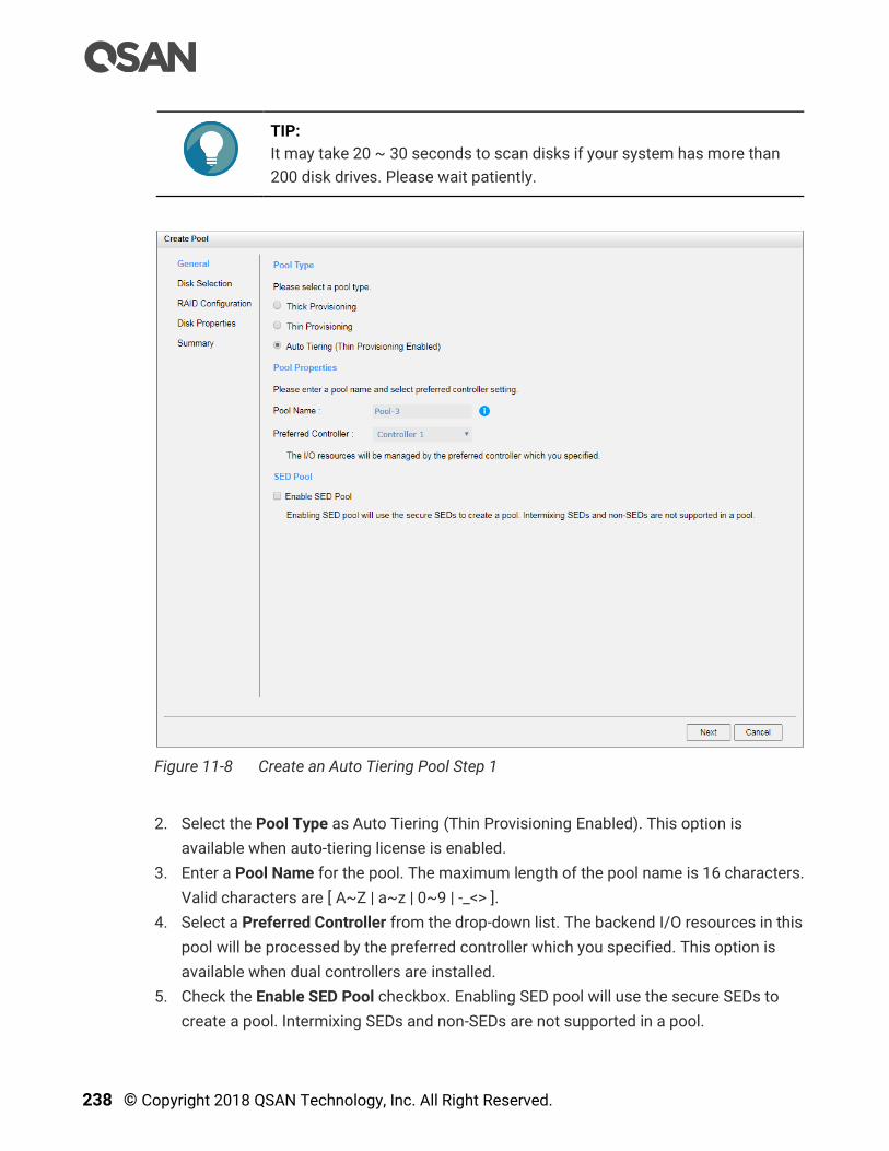
238 © Copyright 2018 QSAN Technology, Inc. All Right Reserved.
TIP:
It may take 20 ~ 30 seconds to scan disks if your system has more than
200 disk drives. Please wait patiently.
Figure 11-8 Create an Auto Tiering Pool Step 1
2. Select the Pool Type as Auto Tiering (Thin Provisioning Enabled). This option is
available when auto-tiering license is enabled.
3. Enter a Pool Name for the pool. The maximum length of the pool name is 16 characters.
Valid characters are [ A~Z | a~z | 0~9 | -_<> ].
4. Select a Preferred Controller from the drop-down list. The backend I/O resources in this
pool will be processed by the preferred controller which you specified. This option is
available when dual controllers are installed.
5. Check the Enable SED Pool checkbox. Enabling SED pool will use the secure SEDs to
create a pool. Intermixing SEDs and non-SEDs are not supported in a pool.

Auto Tiering 239
6. Click the Next button to continue.
Figure 11-9 Create an Auto Tiering Pool Step 2
7. Please select disks for pool and select at least two disk types of disks to add tiers an
auto tiering pool. Each tier is a disk group. The maximum quantity of disk in a disk group
is 64. Select an Enclosure ID from the drop-down list to select disks from expansion
enclosures.
8. Click the Next button to continue.
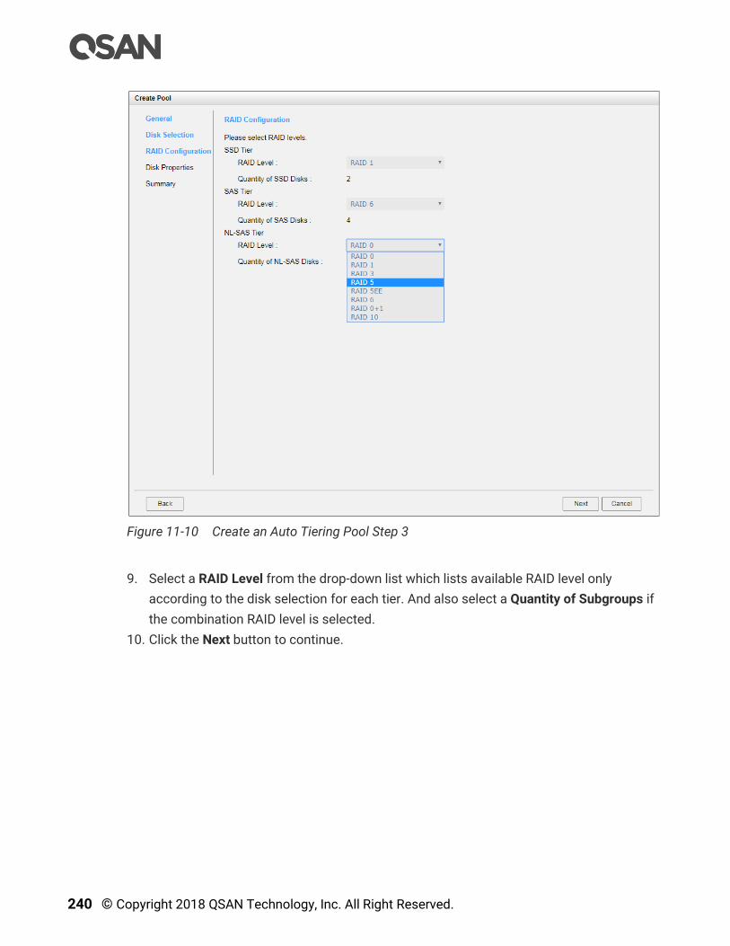
240 © Copyright 2018 QSAN Technology, Inc. All Right Reserved.
Figure 11-10 Create an Auto Tiering Pool Step 3
9. Select a RAID Level from the drop-down list which lists available RAID level only
according to the disk selection for each tier. And also select a Quantity of Subgroups if
the combination RAID level is selected.
10. Click the Next button to continue.

Auto Tiering 241
Figure 11-11 Create an Auto Tiering Pool Step 4
11. Disk properties can also be configured optionally in this step:
。 Enable Disk Write Cache: Check to enable the write cache option of disks. Enabling
disk write cache will improve write I/O performance but have a risk of losing data
when power failure.
。 Enable Disk Read-ahead: Check to enable the read-ahead function of disks. System
will preload data to disk buffer based on previously retrieved data. This feature will
efficiently improve the performance of sequential data retrieved.
。 Enable Disk Command Queuing: Check to enable the command queue function of
disks. Send multiple commands to a disk at once to improve performance.
。 Enable Disk Standby: Check to enable the auto spin down function of disks. The
disks will be spun down for power saving when they are idle for the period of time
specified.
12. Click the Next button to continue.

242 © Copyright 2018 QSAN Technology, Inc. All Right Reserved.
Figure 11-12 Create an Auto Tiering Pool Wizard Step 5
13. By default, we set relocation schedule at 00:00 daily, relocation period set to 00:00
which means let relocation process run until it finishes, and relocation rate to fast.
14. After confirmation at summary page, click the Finish button to create a pool.
Figure 11-13 An Auto Tiering Pool is Created
15. The pool has been created. If necessary, click the Create Pool button again to create
others.
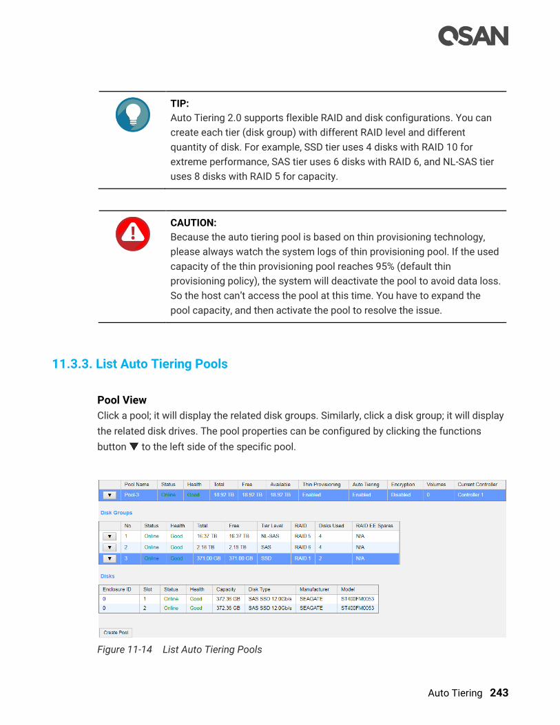
Auto Tiering 243
TIP:
Auto Tiering 2.0 supports flexible RAID and disk configurations. You can
create each tier (disk group) with different RAID level and different
quantity of disk. For example, SSD tier uses 4 disks with RAID 10 for
extreme performance, SAS tier uses 6 disks with RAID 6, and NL-SAS tier
uses 8 disks with RAID 5 for capacity.
CAUTION:
Because the auto tiering pool is based on thin provisioning technology,
please always watch the system logs of thin provisioning pool. If the used
capacity of the thin provisioning pool reaches 95% (default thin
provisioning policy), the system will deactivate the pool to avoid data loss.
So the host can’t access the pool at this time. You have to expand the
pool capacity, and then activate the pool to resolve the issue.
11.3.3. List Auto Tiering Pools
Pool View
Click a pool; it will display the related disk groups. Similarly, click a disk group; it will display
the related disk drives. The pool properties can be configured by clicking the functions
button to the left side of the specific pool.
Figure 11-14 List Auto Tiering Pools
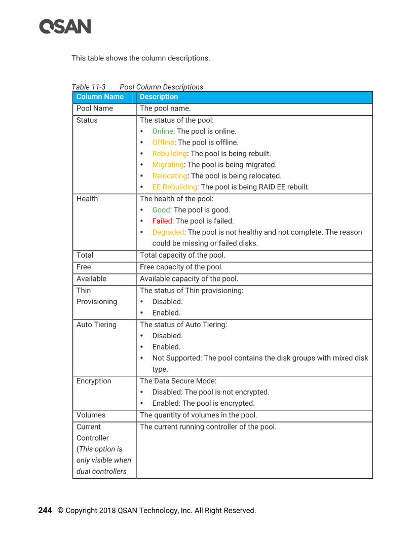
244 © Copyright 2018 QSAN Technology, Inc. All Right Reserved.
This table shows the column descriptions.
Table 11-3 Pool Column Descriptions
Column Name Description
Pool Name The pool name.
Status The status of the pool:
Online: The pool is online.
Offline: The pool is offline.
Rebuilding: The pool is being rebuilt.
Migrating: The pool is being migrated.
Relocating: The pool is being relocated.
EE Rebuilding: The pool is being RAID EE rebuilt.
Health The health of the pool:
Good: The pool is good.
Failed: The pool is failed.
Degraded: The pool is not healthy and not complete. The reason
could be missing or failed disks.
Total Total capacity of the pool.
Free Free capacity of the pool.
Available Available capacity of the pool.
Thin
Provisioning
The status of Thin provisioning:
Disabled.
Enabled.
Auto Tiering The status of Auto Tiering:
Disabled.
Enabled.
Not Supported: The pool contains the disk groups with mixed disk
type.
Encryption The Data Secure Mode:
Disabled: The pool is not encrypted.
Enabled: The pool is encrypted.
Volumes The quantity of volumes in the pool.
Current
Controller
(This option is
only visible when
dual controllers
The current running controller of the pool.

Auto Tiering 245
are installed.)
Table 11-4 Disk Group Column Descriptions
Column Name Description
No The number of disk group.
Status The status of the disk group:
Online: The disk group is online.
Offline: The disk group is offline.
Rebuilding: The disk group is being rebuilt.
Migrating: The disk group is being migrated.
Relocating: The disk group is being relocated.
EE Rebuilding: The disk group is being RAID EE rebuilt.
Health The health of the disk group:
Good: The disk group is good.
Failed: The disk group fails.
Degraded: The disk group is not healthy and not completed. The
reason could be lack of disk(s) or have failed disk.
Total Total capacity of the disk group.
Free Free capacity of the disk group.
RAID The RAID level of the disk group.
Disks Used The quantity of disk drives in the disk group.
RAID EE Spare The quantity of RAID EE spare disk drives in the disk group. Display
N/A is the RAID level is traditional.
Table 11-5 Disk Column Descriptions
Column Name Description
Enclosure ID The enclosure ID.
Slot The position of the disk drive.
Status The status of the disk drive:
Online: The disk drive is online.
Missing: The disk drive is missing in the pool.
Rebuilding: The disk drive is being rebuilt.
Transitioning: The disk drive is being migrated or is replaced by
another disk when rebuilding occurs.
Scrubbing: The disk drive is being scrubbed.
Check Done: The disk drive has been checked the disk health.
Copying Back: The disk drive is being copied back.

246 © Copyright 2018 QSAN Technology, Inc. All Right Reserved.
Health The health of the disk drive:
Good: The disk drive is good.
Failed: The disk drive is failed.
Error Alert: S.M.A.R.T. error alerts.
Read Errors: The disk drive has unrecoverable read errors.
Capacity The capacity of the disk drive.
Disk Type The type of the disk drive:
[ SAS HDD | NL-SAS HDD | SAS SSD | SATA SSD ]
[ 12.0Gb/s | 6.0Gb/s | 3.0Gb/s | 1.5Gb/s ]
Manufacturer The manufacturer of the disk drive.
Model The model name of disk drive.
Auto Tiering View
The Auto Tiering function tab in the Pools function submenu is only visible when auto
tiering license is enabled. Click a pool; it will display the related tiering status. The pool
properties can be configured by clicking the functions button to the left side of the
specific pool.
Figure 11-15 Auto Tiering Pools and Status
This table shows the column descriptions.
Table 11-6 Pool Tiering Status Column Descriptions
Column Name Description
Tier Level Tier categories, there are SSD, SAS, Nearline SAS, and SATA. The
system will hide the tiers without any disk groups.
Tier Capacity Total capacity of the tier.
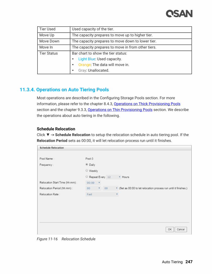
Auto Tiering 247
Tier Used Used capacity of the tier.
Move Up The capacity prepares to move up to higher tier.
Move Down The capacity prepares to move down to lower tier.
Move In The capacity prepares to move in from other tiers.
Tier Status Bar chart to show the tier status:
Light Blue: Used capacity.
Orange: The data will move in.
Gray: Unallocated.
11.3.4. Operations on Auto Tiering Pools
Most operations are described in the Configuring Storage Pools section. For more
information, please refer to the chapter 8.4.3, Operations on Thick Provisioning Pools
section and the chapter 9.3.3, Operations on Thin Provisioning Pools section. We describe
the operations about auto tiering in the following.
Schedule Relocation
Click ▼ -> Schedule Relocation to setup the relocation schedule in auto tiering pool. If the
Relocation Period sets as 00:00, it will let relocation process run until it finishes.
Figure 11-16 Relocation Schedule
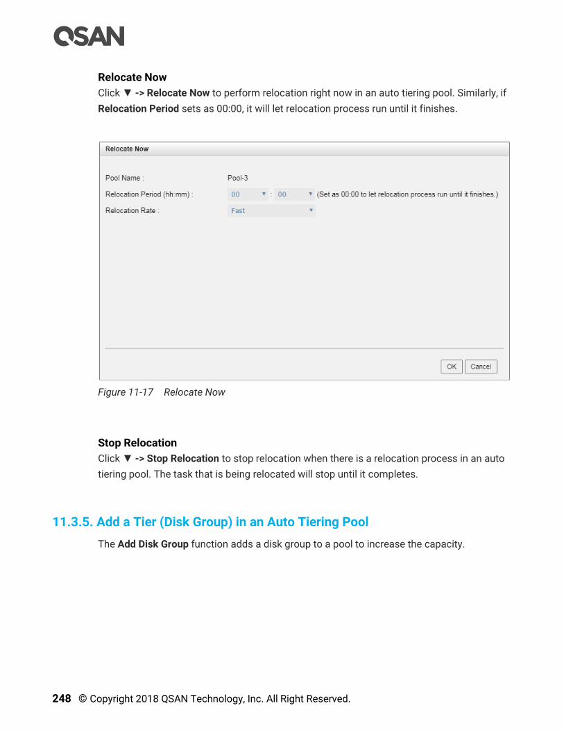
248 © Copyright 2018 QSAN Technology, Inc. All Right Reserved.
Relocate Now
Click ▼ -> Relocate Now to perform relocation right now in an auto tiering pool. Similarly, if
Relocation Period sets as 00:00, it will let relocation process run until it finishes.
Figure 11-17 Relocate Now
Stop Relocation
Click ▼ -> Stop Relocation to stop relocation when there is a relocation process in an auto
tiering pool. The task that is being relocated will stop until it completes.
11.3.5. Add a Tier (Disk Group) in an Auto Tiering Pool
The Add Disk Group function adds a disk group to a pool to increase the capacity.
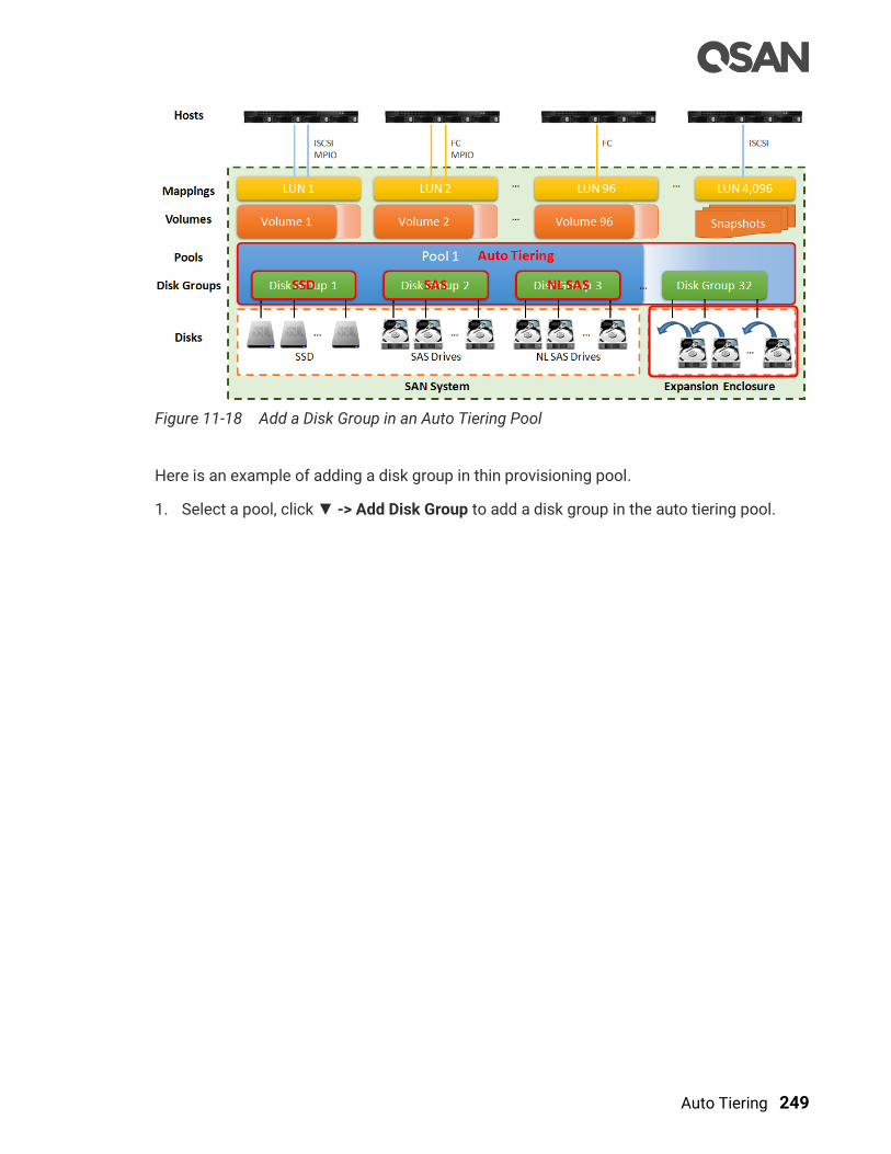
Auto Tiering 249
Figure 11-18 Add a Disk Group in an Auto Tiering Pool
Here is an example of adding a disk group in thin provisioning pool.
1. Select a pool, click ▼ -> Add Disk Group to add a disk group in the auto tiering pool.

250 © Copyright 2018 QSAN Technology, Inc. All Right Reserved.
Figure 11-19 Add Disk Group
2. Select a RAID Level from the drop-down list and also select a Quantity of Subgroups if
the combination RAID level is selected.
3. Please select disks to add a disk group. The maximum quantity of disk in a disk group is
64. Select an Enclosure from the drop-down list to select disks from the expansion
enclosures.
4. Click the OK button to add a disk group.

Auto Tiering 251
11.3.6. Hot Spares in an Auto Tiering Pool
In an auto tiering pool, hot spare drives can only replace the drives of the same disk type.
For example, a SSD tier can only be assigned SSD type drives as hot spares drives.
Figure 11-20 Hot Spares in Auto Tiering Pool
11.4. Configure Volumes
This section will describe the operations of configuring volume in auto tiering pool.
11.4.1. Create a Volume in an Auto Tiering Pool
Here is an example of creating a volume in an auto tiering pool.
1. Select the Volumes function submenu, click the Create Volume button.
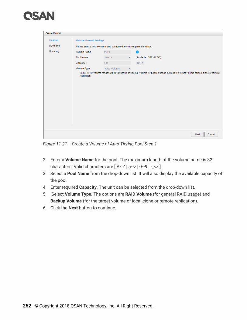
252 © Copyright 2018 QSAN Technology, Inc. All Right Reserved.
Figure 11-21 Create a Volume of Auto Tiering Pool Step 1
2. Enter a Volume Name for the pool. The maximum length of the volume name is 32
characters. Valid characters are [ A~Z | a~z | 0~9 | -_<> ].
3. Select a Pool Name from the drop-down list. It will also display the available capacity of
the pool.
4. Enter required Capacity. The unit can be selected from the drop-down list.
5. Select Volume Type. The options are RAID Volume (for general RAID usage) and
Backup Volume (for the target volume of local clone or remote replication).
6. Click the Next button to continue.

Auto Tiering 253
Figure 11-22 Create a Volume of Auto Tiering Pool Step 2
7. Volume advanced settings can also be configured optionally in this step:
。 Block Size: The options are 512 Bytes to 4,096 Bytes.
。 Priority: The options are High, Medium, and Low. The priority compares to other
volumes. Set it as High if the volume has many I/O.
。 Background I/O Priority: The options are High, Medium, and Low. It will influence
volume initialization, rebuild, and migration.
。 Tiering Policy: The options are Auto Tiering, Start Highest then Auto Tiering, High
Available Tier, Lowest Tier, and No Data Movement. Please refer to the chapter
11.2.3, Tiering Policies section for detail.
。 Enable Cache Mode (Write-back Cache): Check to enable cache mode function of
volume. Write back optimizes the system speed but comes with the risk where the
data may be inconsistent between cache and disks in one short time interval.
。 Enable Video Editing Mode: Check to enable video editing mode function. It is
optimized for video editing usage. Please enable it when your application is in video
editing environment. This option provides a more stable performance figure without
high and low peaks but slower in average.
。 Enable Read-ahead: Check to enable the read ahead function of volume. The system
will discern what data will be needed next based on what was just retrieved from
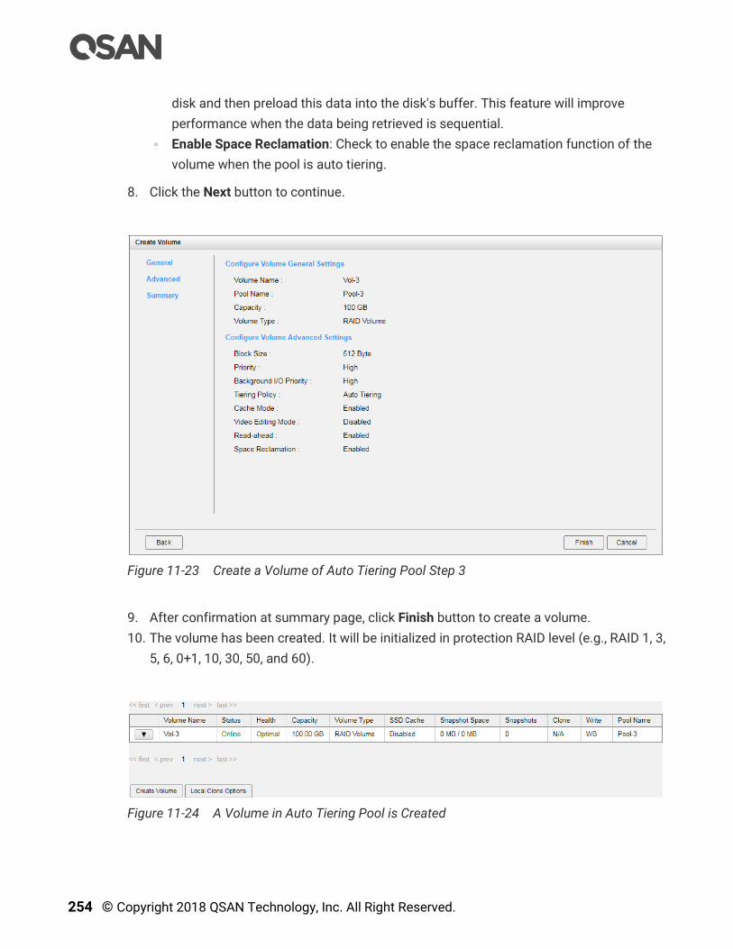
254 © Copyright 2018 QSAN Technology, Inc. All Right Reserved.
disk and then preload this data into the disk's buffer. This feature will improve
performance when the data being retrieved is sequential.
。 Enable Space Reclamation: Check to enable the space reclamation function of the
volume when the pool is auto tiering.
8. Click the Next button to continue.
Figure 11-23 Create a Volume of Auto Tiering Pool Step 3
9. After confirmation at summary page, click Finish button to create a volume.
10. The volume has been created. It will be initialized in protection RAID level (e.g., RAID 1, 3,
5, 6, 0+1, 10, 30, 50, and 60).
Figure 11-24 A Volume in Auto Tiering Pool is Created

Auto Tiering 255
11. A volume has been created. If necessary, click the Create Volume button to create
another.
TIP:
SANOS supports instant RAID volume availability. The volume can be
used immediately when it is initializing or rebuilding.
TIP:
If the pool contains some disk drives of 4Kn type, it is not available to set
512, 1024, or 2048 block size. When the case happens, it will pop up a
warning message and suggest changing the block size to 4096.
11.4.2. List Volumes and Operations on Volumes
Most operations are described in the chapter 8.5, Configuring Volumes section. For more
information about list volume, please refer to the chapter 8.5.2, List Volumes section. For
more information about operations on volumes, please refer to the chapter 8.5.3, Operations
on Volumes section. We describe auto tiering operations below.
Change Volume Properties
Click ▼ -> Change Volume Properties to change the volume properties of the volume.

256 © Copyright 2018 QSAN Technology, Inc. All Right Reserved.
Figure 11-25 Change Volume Properties
Reclaim Space with Thin Provisioning Pool
Click ▼ -> Space Reclamation to reclaim space from the volume when the volume is in an
auto tiering pool. For more information about space reclamation, please refer to the chapter
9.2.2, Space Reclamation section.
11.5. Configure LUN Mappings and Connect by Host Initiator
Next step you can configure LUN mapping and connect by host initiator. For more
information about LUN mapping, please refer to the chapter 8.6, Configure LUN Mappings
section for detail. For more information about host initiator, please refer to the chapter 8.7,
Connect by Host Initiator section for detail.
11.6. Transfer to Auto Tiering Pool
This section describes thick provisioning pool or thin provisioning pool transfer to auto
tiering one. If auto tiering license is enabled, the thick or thin provisioning pool without disk
group of mixed disk type can be transferred to the auto tiering pool by Add Disk Group
option.

Auto Tiering 257
Also note that the thick provisioning pool is preconfigured the space, after transferring to
the auto tiering, the original disk group in the thick provisioning pool will be the lowest tier.
When auto tiering mechanism is running, the hot data are copied to higher tier, but still
occupy the space of the original block. If the data is cold, it will return to the original block
space. So the total capacity of the pool does not change even adding the capacity of higher
tiers.
Figure 11-26 Block Map of Thick Provisioning Pool Transferring to Auto Tiering
Thin provisioning is dynamic allocation of space, if the hot data is moved up to the higher
tier; it will release the original block space. So the total capacity is the sum of all tiers.
Figure 11-27 Block Map of Thin Provisioning Pool Transferring to Auto Tiering
CAUTION:
The action of transferring to auto tiering is irreversible. Consider all
possible consequences before making this change.

258 © Copyright 2018 QSAN Technology, Inc. All Right Reserved.
11.6.1. Transfer from Thick Provisioning Pool to Auto Tiering
First of all, make sure the auto tiering license is enabled. For more information about
enabling license operation, please refer to the chapter 11.3.1, Enable Auto Tiering License
section. And then use Add Disk Group function to add another tier (disk group). Here is an
example of transfer thick provisioning pool to auto tiering one.
1. Create a thick provisioning pool with SAS disk drives. Auto Tiering status is Disabled.
Figure 11-28 Transfer Thick Provisioning Pool to Auto Tiering Step 1
2. Click ▼ -> Add Disk Group to transfer from a thick provisioning pool to an auto tiering
pool. Select Enabled from the Auto Tiering drop-down list. The tier (disk group) must be
added one at a time. Select the RAID Level and Select Disks, and then click the OK
button.
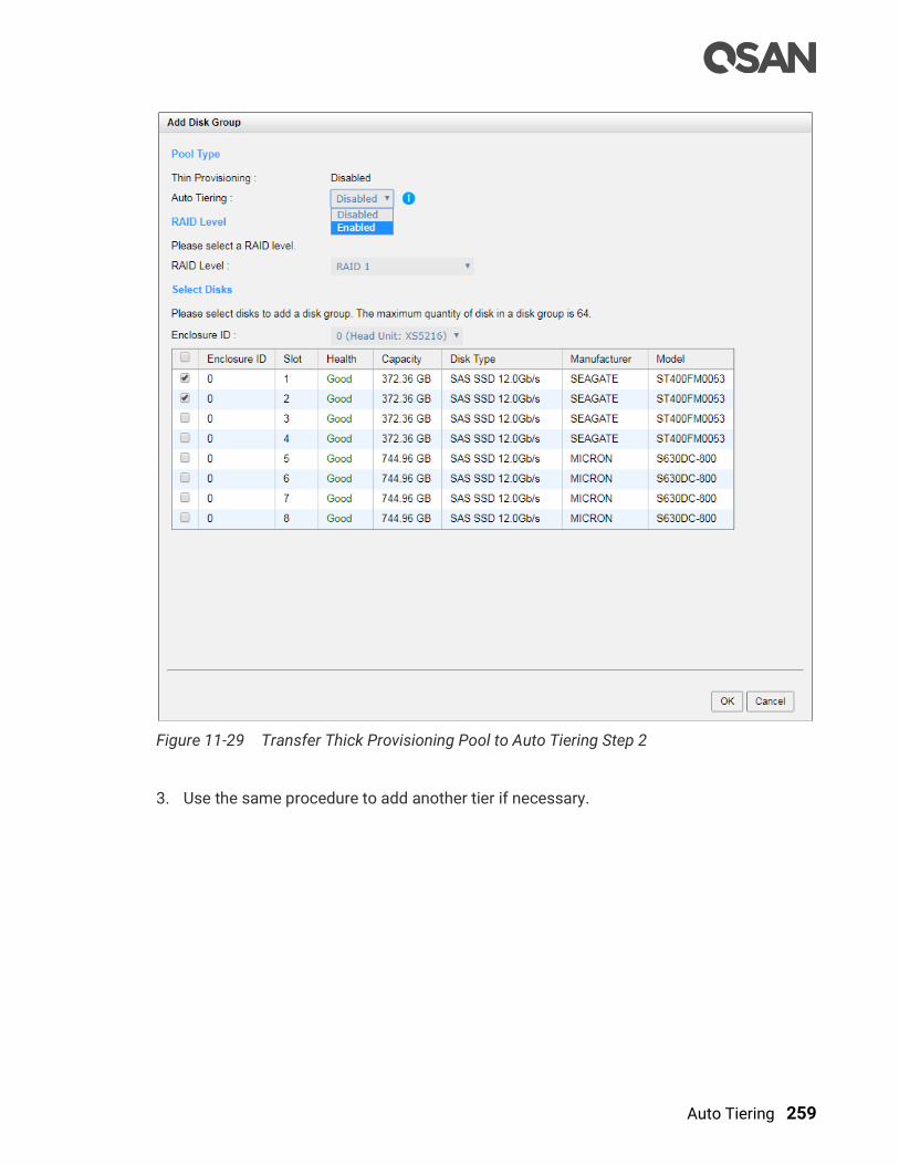
Auto Tiering 259
Figure 11-29 Transfer Thick Provisioning Pool to Auto Tiering Step 2
3. Use the same procedure to add another tier if necessary.
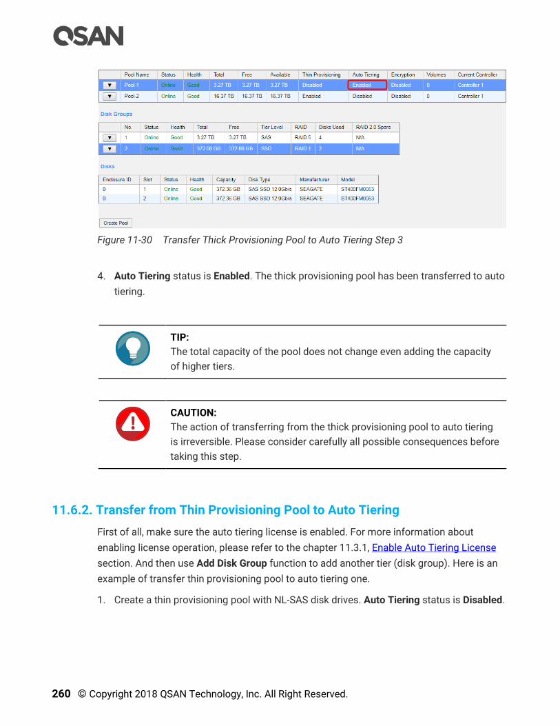
260 © Copyright 2018 QSAN Technology, Inc. All Right Reserved.
Figure 11-30 Transfer Thick Provisioning Pool to Auto Tiering Step 3
4. Auto Tiering status is Enabled. The thick provisioning pool has been transferred to auto
tiering.
TIP:
The total capacity of the pool does not change even adding the capacity
of higher tiers.
CAUTION:
The action of transferring from the thick provisioning pool to auto tiering
is irreversible. Please consider carefully all possible consequences before
taking this step.
11.6.2. Transfer from Thin Provisioning Pool to Auto Tiering
First of all, make sure the auto tiering license is enabled. For more information about
enabling license operation, please refer to the chapter 11.3.1, Enable Auto Tiering License
section. And then use Add Disk Group function to add another tier (disk group). Here is an
example of transfer thin provisioning pool to auto tiering one.
1. Create a thin provisioning pool with NL-SAS disk drives. Auto Tiering status is Disabled.
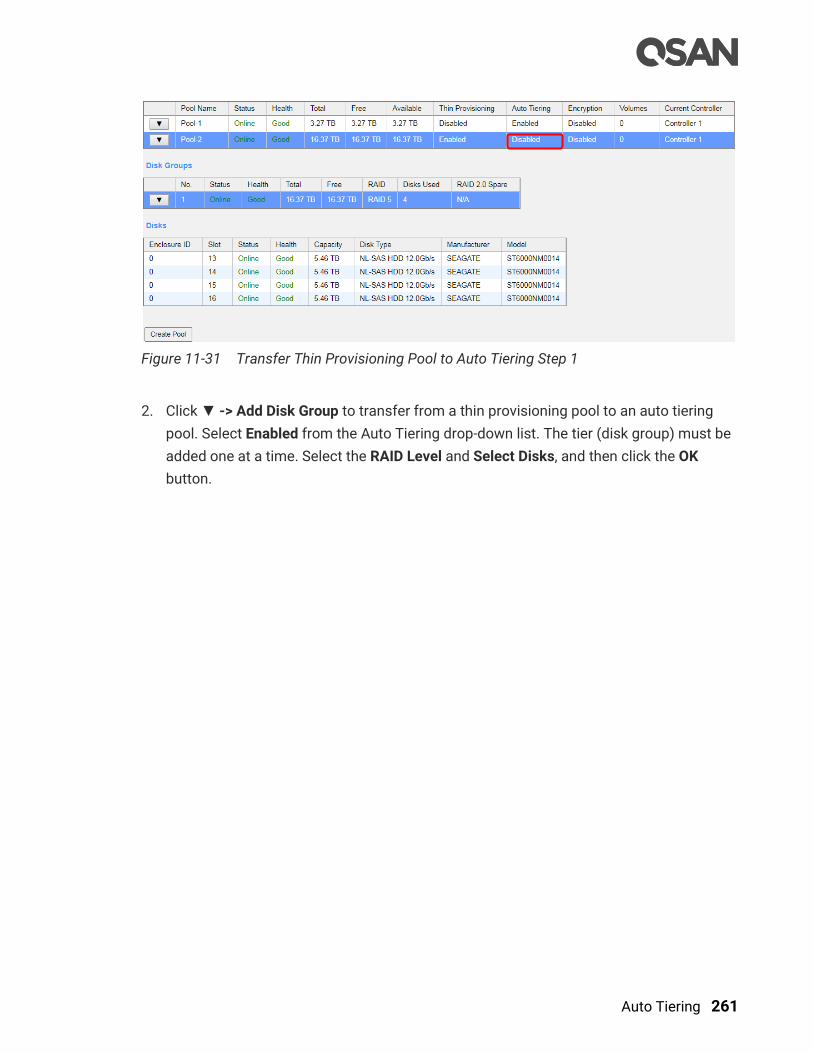
Auto Tiering 261
Figure 11-31 Transfer Thin Provisioning Pool to Auto Tiering Step 1
2. Click ▼ -> Add Disk Group to transfer from a thin provisioning pool to an auto tiering
pool. Select Enabled from the Auto Tiering drop-down list. The tier (disk group) must be
added one at a time. Select the RAID Level and Select Disks, and then click the OK
button.
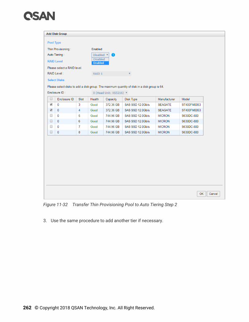
262 © Copyright 2018 QSAN Technology, Inc. All Right Reserved.
Figure 11-32 Transfer Thin Provisioning Pool to Auto Tiering Step 2
3. Use the same procedure to add another tier if necessary.

Auto Tiering 263
Figure 11-33 Transfer Thin Provisioning Pool to Auto Tiering Step 3
4. Auto Tiering status is Enabled. The thin provisioning pool has been transferred to auto
tiering.
TIP:
The total capacity of the pool is the sum of all tiers.
CAUTION:
The action of transferring from the thin provisioning pool to auto tiering is
irreversible. Please consider carefully all possible consequences before
taking this step.
11.7. SSD Cache vs. Auto Tiering
The SSD cache and auto tiering solutions can work together, and complement each other. A
key difference between tiering and cache is that tiering moves data to SSD instead of simply
caching it. Tiering can also move data both from slower storage to faster storage and vice
versa. But SSD cache is essentially a one-way transaction. When the cache is done with the
data it was accelerating it simply nullifies it instead of copying it back to HDD. The
important difference between moves and copies is that a cache does not need to have the
redundancy that tiering does. Tiering stores the only copy of data for potentially a
considerable period of time so it needs to have full data redundancy like RAID or mirroring.
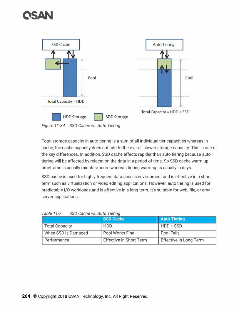
264 © Copyright 2018 QSAN Technology, Inc. All Right Reserved.
Figure 11-34 SSD Cache vs. Auto Tiering
Total storage capacity in auto tiering is a sum of all individual tier capacities whereas in
cache, the cache capacity does not add to the overall slower storage capacity. This is one of
the key differences. In addition, SSD cache affects rapider than auto tiering because auto
tiering will be affected by relocation the data in a period of time. So SSD cache warm-up
timeframe is usually minutes/hours whereas tiering warm-up is usually in days.
SSD cache is used for highly frequent data access environment and is effective in a short
term such as virtualization or video editing applications. However, auto tiering is used for
predictable I/O workloads and is effective in a long term. It's suitable for web, file, or email
server applications.
Table 11-7 SSD Cache vs. Auto Tiering
SSD Cache Auto Tiering
Total Capacity HDD HDD + SSD
When SSD is Damaged Pool Works Fine Pool Fails
Performance Effective in Short Term Effective in Long Term
Data Backup 265
12. Data Backup
This chapter describes an overview and operations of data backup options in SANOS.
SANOS provides built-in data backup services for protecting data from most unpredictable
accidents including:
Volume snapshot which is described in the Managing Snapshots section.
Local volume cloning which is described in the Manage Local Clones section.
Remote replication to have data duplicated to the remote sites, the function is described
in the Managing Remote Replications section.
The DATA BACKUP function menu provides submenus of Snapshots and Replications.
Clone function is built in the Volumes function tab of the Volumes function submenu.
12.1. Managing Snapshots
A volume snapshot is based on copy-on-write technology. It’s a block-based and differential
backup mechanism. Snapshot functionality is designed to be highly efficient, it keeps a
point in time record of block-level, incremental data changes of the target LUN volume.
Snapshot can help recover a LUN volume to a previous state quickly to meet enterprise SLA
(Service Level Agreement) requirements of RPO (Recovery Point Objectives) and RTO
(Recovery Time Objective).
Snapshot is the easiest and most effective measure to protect against ransomware attacks,
virus attacks, accidental file deletion, accidental file modification, or unstable system
hardware caused by a bad I/O cable connection, unstable power supply… etc.
12.1.1. Theory of Operation
Snapshot-on-the-box captures the instant state of data in the target volume in a logical
sense. The underlying logic is copy-on-write, moving out the data which would be written to
certain location where a write action occurs since the time of data capture. The certain
location, named as “Snapshot Volume”, is essentially a new volume which can be attached
to a LUN provisioned to a host as a disk like other ordinary volumes in the system.
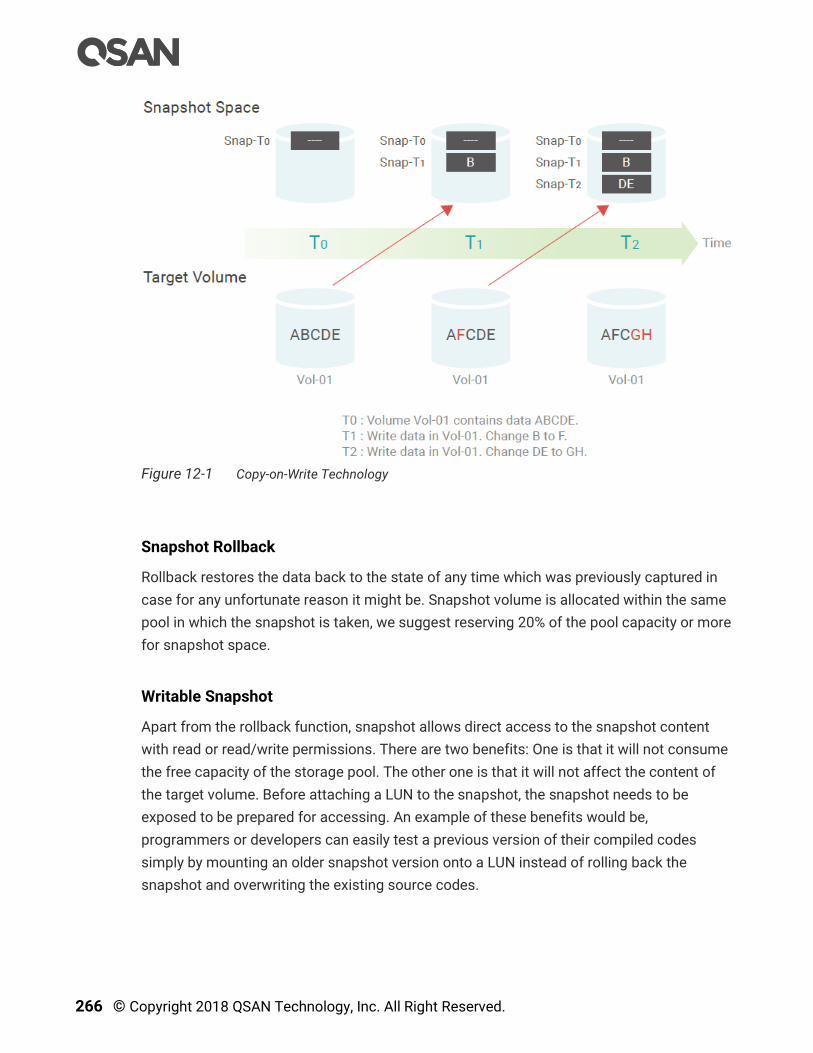
266 © Copyright 2018 QSAN Technology, Inc. All Right Reserved.
Figure 12-1 Copy-on-Write Technology
Snapshot Rollback
Rollback restores the data back to the state of any time which was previously captured in
case for any unfortunate reason it might be. Snapshot volume is allocated within the same
pool in which the snapshot is taken, we suggest reserving 20% of the pool capacity or more
for snapshot space.
Writable Snapshot
Apart from the rollback function, snapshot allows direct access to the snapshot content
with read or read/write permissions. There are two benefits: One is that it will not consume
the free capacity of the storage pool. The other one is that it will not affect the content of
the target volume. Before attaching a LUN to the snapshot, the snapshot needs to be
exposed to be prepared for accessing. An example of these benefits would be,
programmers or developers can easily test a previous version of their compiled codes
simply by mounting an older snapshot version onto a LUN instead of rolling back the
snapshot and overwriting the existing source codes.
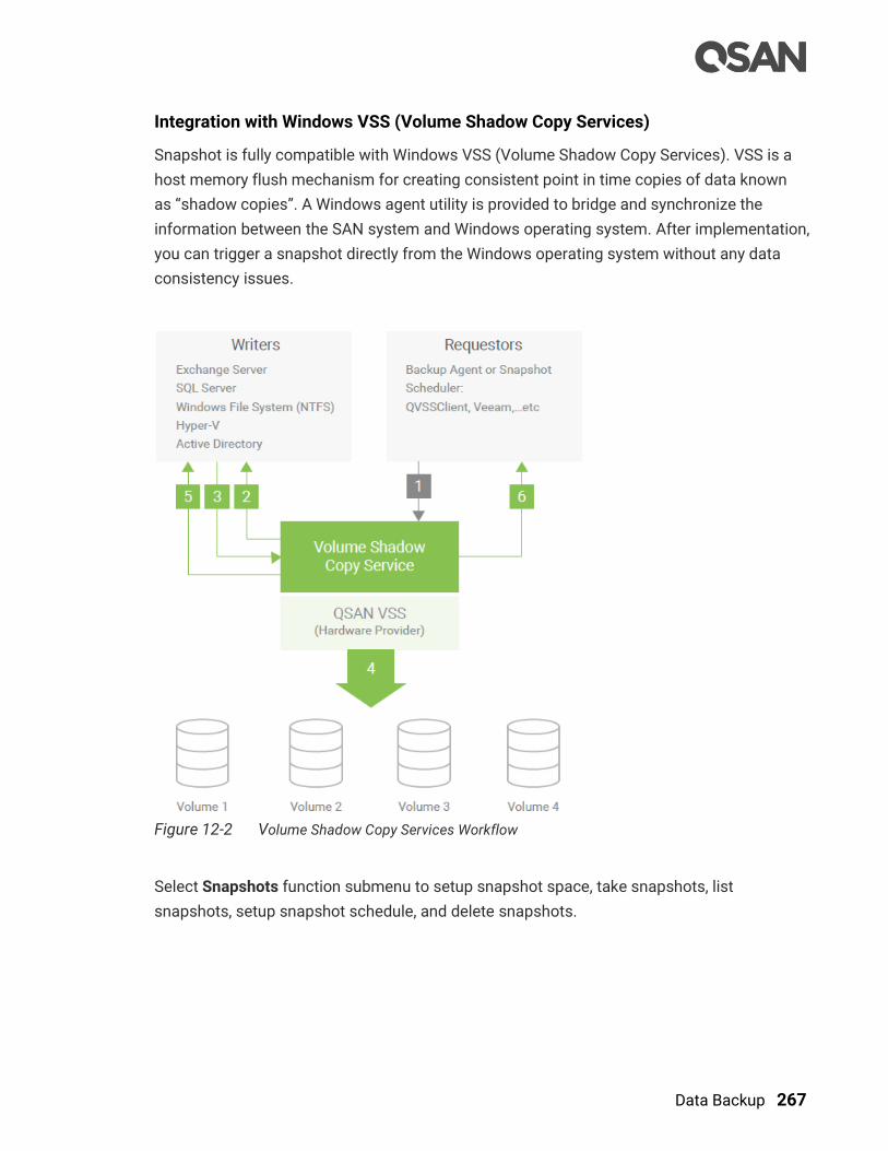
Data Backup 267
Integration with Windows VSS (Volume Shadow Copy Services)
Snapshot is fully compatible with Windows VSS (Volume Shadow Copy Services). VSS is a
host memory flush mechanism for creating consistent point in time copies of data known
as “shadow copies”. A Windows agent utility is provided to bridge and synchronize the
information between the SAN system and Windows operating system. After implementation,
you can trigger a snapshot directly from the Windows operating system without any data
consistency issues.
Figure 12-2 Volume Shadow Copy Services Workflow
Select Snapshots function submenu to setup snapshot space, take snapshots, list
snapshots, setup snapshot schedule, and delete snapshots.
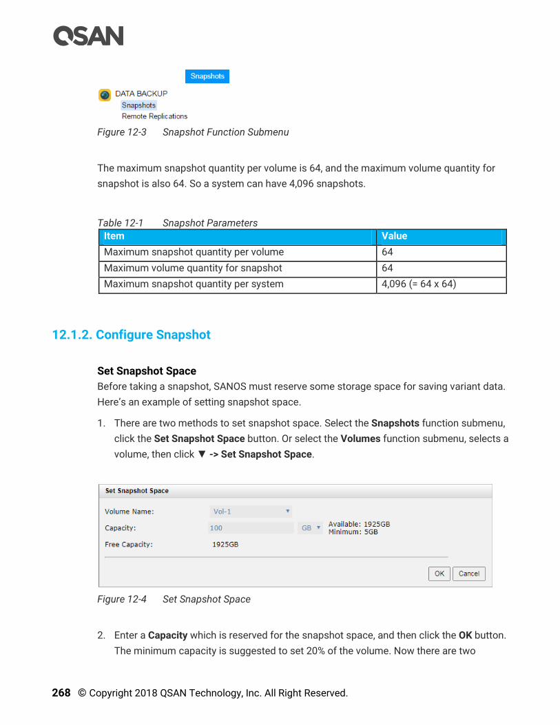
268 © Copyright 2018 QSAN Technology, Inc. All Right Reserved.
Figure 12-3 Snapshot Function Submenu
The maximum snapshot quantity per volume is 64, and the maximum volume quantity for
snapshot is also 64. So a system can have 4,096 snapshots.
Table 12-1 Snapshot Parameters
Item Value
Maximum snapshot quantity per volume 64
Maximum volume quantity for snapshot 64
Maximum snapshot quantity per system 4,096 (= 64 x 64)
12.1.2. Configure Snapshot
Set Snapshot Space
Before taking a snapshot, SANOS must reserve some storage space for saving variant data.
Here’s an example of setting snapshot space.
1. There are two methods to set snapshot space. Select the Snapshots function submenu,
click the Set Snapshot Space button. Or select the Volumes function submenu, selects a
volume, then click ▼ -> Set Snapshot Space.
Figure 12-4 Set Snapshot Space
2. Enter a Capacity which is reserved for the snapshot space, and then click the OK button.
The minimum capacity is suggested to set 20% of the volume. Now there are two

Data Backup 269
capacities in Snapshot Space column in the Volumes function tab. The first capacity is
current used snapshot space, and the second capacity is reserved total snapshot space.
Take a Snapshot
Here’s an example of taking a snapshot of the volume.
1. There are two methods to take snapshot. Select the Snapshots function submenu, click
Take Snapshot button. Or select the Volumes function submenu, selects a volume, then
click ▼ -> Take Snapshot.
Figure 12-5 Take Snapshot
2. Enter a Snapshot Name. The maximum length of the snapshot name is 32 characters.
Valid characters are [ A~Z | a~z | 0~9 | -_<> ].
3. Click the OK button. The snapshot is taken.
List Snapshots
Select the Snapshots function submenu, the drop-down lists at the top enable you to switch
the volumes.
Figure 12-6 List Snapshots
This table shows the column descriptions.

270 © Copyright 2018 QSAN Technology, Inc. All Right Reserved.
Table 12-2 Snapshot Column Descriptions
Column Name Description
Snapshot Name The snapshot name.
Status The status of the snapshot:
N/A: The snapshot is normal.
Replicated: The snapshot is for clone or replication usage.
Undeletable: The snapshot is undeletable.
Aborted: The snapshot is over space and abort.
Health The health of the snapshot:
Good: The snapshot is good.
Failed: The snapshot fails.
Used The amount of the snapshot space that has been used.
Exposure The snapshot is exposed or not.
Permission The permission of the snapshot:
N/A: Unknown when the snapshot is unexposed.
Read-write: The snapshot can be read / write.
Read-only: The snapshot is read only.
LUN The LUN status of the snapshot:
None: The snapshot is not mapped any LUN.
Mapped: The snapshot is mapped a LUN.
Time Created The created time of the snapshot.
Select the Volumes function submenu, selects a volume, then click ▼ -> List Snapshots.
Figure 12-7 List Snapshots
Expose Snapshot
Here’s an example of exposing a snapshot.

Data Backup 271
1. Select the Snapshots function submenu, click ▼ -> Expose Snapshot to set writable
snapshot capacity to expose the snapshot.
Figure 12-8 Set Writable Snapshot Capacity to Expose Snapshot
2. Enter a Capacity which is reserved for the snapshot. If the size is 0, the exposed
snapshot will be read only. Otherwise, the exposed snapshot can be read / written, and
the size will be the maximum capacity for writing.
3. Click the OK button.
4. Click ▼ -> Map LUN to map a LUN to the snapshot. Please refer to the chapter 8.6,
Configure LUN Mappings section for detail.
5. Done. The Snapshot can be used as a volume.
TIP:
If the capacity of exposed snapshot is set to 0, the snapshot is read only.
If it is not 0, the snapshot can be writable and it becomes writable
snapshot.
Unexpose Snapshot
Here’s an example of unexposing a snapshot.
1. Select the Snapshots function submenu, click ▼ -> Unexpose Snapshot to unexposed
snapshot
2. Click OK button.
Configure LUN Mappings
1. Select the Snapshots function submenu, click ▼ -> Map LUN to map a LUN to the
snapshot. Please refer to the chapter 8.6, Configure LUN Mappings section for detail.
2. Click ▼ -> List LUNs to list all LUNs of the snapshot.

272 © Copyright 2018 QSAN Technology, Inc. All Right Reserved.
3. Click ▼ -> Unmap LUNs to unmap LUNs from the snapshot.
Delete One Snapshot
Select Snapshots function submenu, click ▼ -> Delete to delete the snapshot. All snapshots
after deleted one will be deleted.
CAUTION:
If a snapshot has been deleted, the other snapshots which are earlier than
it will also be deleted. The space occupied by these snapshots will be
released after deleting.
Delete All Snapshots
To cleanup all the snapshots, please follow these steps.
1. There are two methods to cleanup snapshots. Select the Snapshots function submenu,
click Delete Snapshots button. Of select the Volumes function submenu, selects a
volume. And then click ▼ -> Delete Snapshots.
2. Click the OK to apply. It will delete all snapshots of the volume and release the snapshot
space.
12.1.3. Configure Rollback Snapshot
Rollback Snapshot
The data in snapshot can rollback to the original volume. Please follow the procedures.
1. Select the Snapshots function submenu, selects a snapshot. And then click ▼ ->
Rollback Snapshot to rollback the snapshot to the volume.
2. Click the OK to apply.
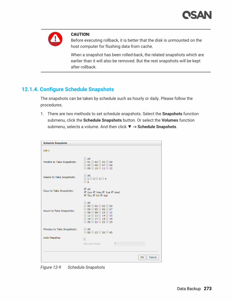
Data Backup 273
CAUTION:
Before executing rollback, it is better that the disk is unmounted on the
host computer for flushing data from cache.
When a snapshot has been rolled-back, the related snapshots which are
earlier than it will also be removed. But the rest snapshots will be kept
after rollback.
12.1.4. Configure Schedule Snapshots
The snapshots can be taken by schedule such as hourly or daily. Please follow the
procedures.
1. There are two methods to set schedule snapshots. Select the Snapshots function
submenu, click the Schedule Snapshots button. Or select the Volumes function
submenu, selects a volume. And then click ▼ -> Schedule Snapshots.
Figure 12-9 Schedule Snapshots

274 © Copyright 2018 QSAN Technology, Inc. All Right Reserved.
2. Check the schedules you want to set. They can be set by monthly, weekly, daily, or hourly.
Check the Auto Mapping box to map a LUN automatically when the snapshot is taken.
And the LUN is allowed to access by the Allowed Hosts column.
3. Click the OK to apply.
INFORMATION:
Daily snapshot will be taken at 00:00 daily.
Weekly snapshot will be taken every Sunday at 00:00.
Monthly snapshot will be taken every first day of the month at 00:00.
12.1.5. Snapshot Notices
Snapshot function applies copy-on-write technique on volume and provides a quick and
efficient backup methodology. When taking a snapshot, it does not copy any data at first
time until a request of data modification comes in. The snapshot copies the original data to
snapshot space and then overwrites the original data with new changes. With this technique,
snapshot only copies the changed data instead of copying whole data. It will save a lot of
disk space.
Data Consistent Snapshot
Before using snapshot, users should understand why sometimes the data becomes
corrupted after rollback of snapshot. Please refer to the following diagram.
When the data is modified from the host computer, the data will pass through file system
and memory of the host (write cache). Then the host will flush the data from memory to
physical disks, no matter the disk is local disk (IDE or SATA), DAS (SCSI or SAS), or SAN
(fibre or iSCSI). From the viewpoint of the storage device, it cannot control the behavior of
the host side. It sometimes happens that when a snapshot is taken, some data is still in
memory and did not flush to disk. Then the snapshot may have an incomplete image of the
original data. The problem does not belong to the storage device. To avoid this data
inconsistency issue between a snapshot and original data, the user has to make the
operating system flushes the data from memory of the host (write cache) into disk before
taking snapshot.

Data Backup 275
Figure 12-10 Host data I/O Route
On Linux and UNIX platforms, a command named sync can be used to make the operating
system flush data from write cache to disk. For the Windows platform, Microsoft also
provides a tool – sync, which does exactly the same thing as the sync command in
Linux/UNIX. It will tell the OS to flush the data on demand. For more information about sync
tool, please refer to http://technet.microsoft.com/en-us/sysinternals/bb897438.aspx
Besides the sync tool, Microsoft developed VSS (volume shadow copy service) to prevent
this issue. VSS is a mechanism for creating consistent “point-in-time” copies of data known
as shadow copies. It is a coordinator between backup software, application (SQL or
Exchange…) and storage systems to make sure snapshots can occur without the problem of
data-irregularities. For more information about the VSS, please refer to
http://technet.microsoft.com/en-us/library/cc785914.aspx. QSAN storage systems fully
support Microsoft VSS.
Run Out of Snapshot Space
Before using snapshot, a snapshot space is needed from pool capacity. After a period of
working snapshot, what if the snapshot size over the snapshot space of user defined? There
are two different situations:
276 © Copyright 2018 QSAN Technology, Inc. All Right Reserved.
1. If there are two or more snapshots existed, the system will try to remove the oldest
snapshots (to release more space for the latest snapshot) until enough space is
released.
2. If there is only one snapshot existed, the snapshot will fail. Because the snapshot space
is run out.
For example, there are two or more snapshots existed on a volume and the latest snapshot
keeps growing. When it comes to the moment that the snapshot space is run out, the
system will try to remove the oldest snapshot to release more space for the latest snapshot
usage. As the latest snapshot is growing, the system keeps removing the old snapshots.
When it comes that the latest snapshot is the only one in system, there is no more snapshot
space which can be released for incoming changes, then snapshot will fail.
Maximum Snapshot Quantity per Volume
There are up to 64 snapshots can be created per volume. What if the 65th snapshot has
been taken? There are two different situations:
1. If the snapshot is configured as schedule snapshot, the latest one (the 65th snapshot)
will replace the oldest one (the first snapshot) and so on.
2. If the snapshot is taken manually, when taking the 65th snapshot will fail and a warning
message will be showed on web user interface.
Rollback and Delete Snapshot
When a snapshot has been rolled back, the related snapshots which are earlier than it will
also be removed. But the rest snapshots will be kept after rollback. If a snapshot has been
deleted, the other snapshots which are earlier than it will also be deleted. The space
occupied by these snapshots will be released after deleting.
12.2. Managing Local Clones
Local clone is used to make a duplicate copy of a volume in the same storage pool as well
as in a separate storage pool within the same enclosure. In setting up local clone task, the
first clone is a full copy. From now on, the cloning is a differential copy, created using
snapshot functionality. Manual and scheduled tasks are available for management flexibility.
In the event that the source volume is broken and it fails, IT managers can quickly switch to
the cloned volume and resume data services.
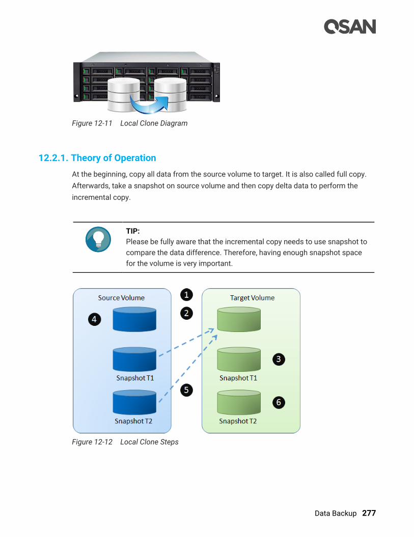
Data Backup 277
Figure 12-11 Local Clone Diagram
12.2.1. Theory of Operation
At the beginning, copy all data from the source volume to target. It is also called full copy.
Afterwards, take a snapshot on source volume and then copy delta data to perform the
incremental copy.
TIP:
Please be fully aware that the incremental copy needs to use snapshot to
compare the data difference. Therefore, having enough snapshot space
for the volume is very important.
Figure 12-12 Local Clone Steps

278 © Copyright 2018 QSAN Technology, Inc. All Right Reserved.
In general, local clone operates as follows:
1. Create a local clone task, 2 snapshots are taken on the Source Volume.
2. Data from the Source Snapshot T1 is copied to the Target Volume.
3. The Target Snapshot T1 is refreshed and becomes the common base.
4. Host keeps writing new data to the Source Volume.
5. At next synchronization, the Source Snapshot T2 is refreshed and copies only the
changes since the last synchronization.
6. The Target Snapshot T2 is refreshed and becomes the common base.
The local clone operations are under the Volumes function tab which provides to setup local
clone task, start or stop the tasks, setup local clone schedule, and delete tasks. The
maximum clone task quantity per volume is 1, and the maximum clone task quantity per
system is 64.
Table 12-3 Local Clone Parameters
Item Value
Maximum clone task quantity per volume
(Maximum clone pairs per source volume)
1
Maximum clone task quantity per system 64
Rollback Local Clone
Rollback local clone operates are in the following:
1. After completing the local clone task, the data can be rolled-back.
2. Exchange the roles of source and target volume, follow the operations on local clone to
create a local clone task. Notice that the data in original volume will be destroyed. You
have to comprehensive consideration before doing.
3. Or create a new target volume to backup to.
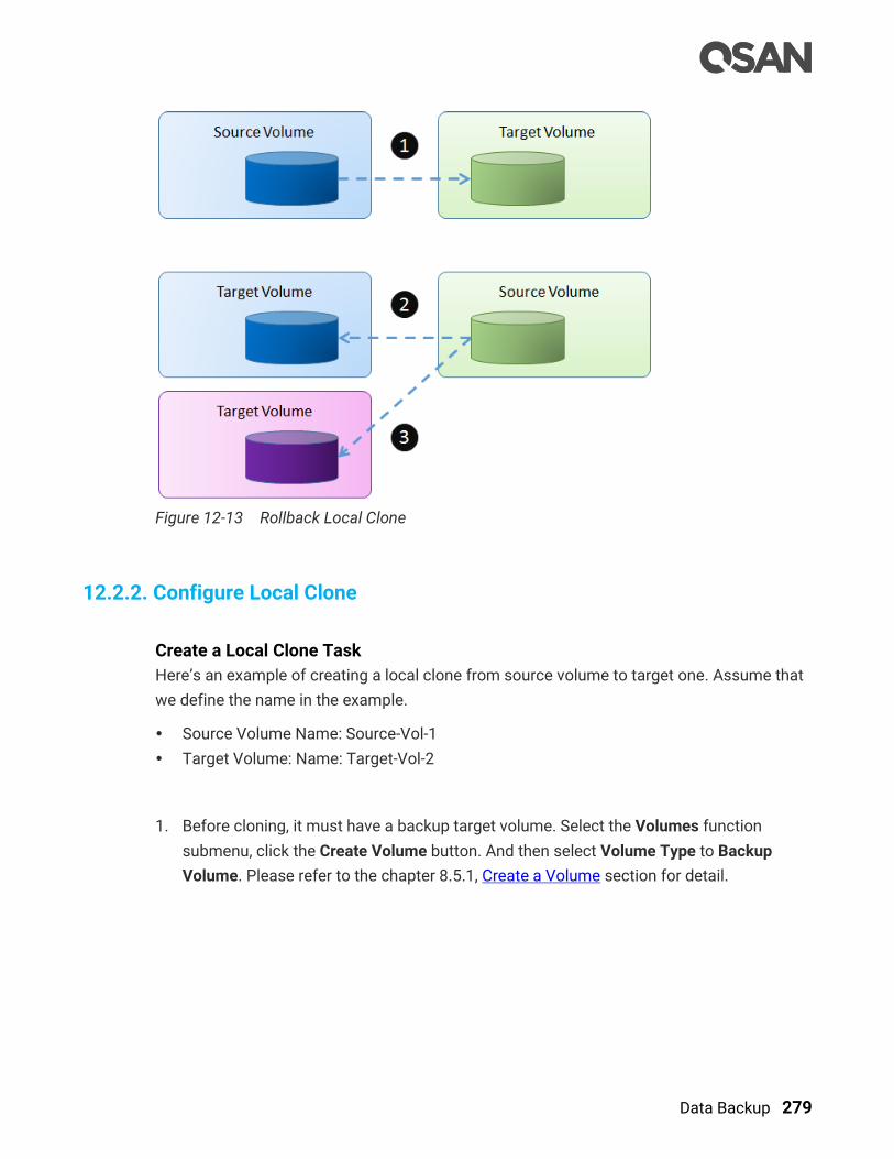
Data Backup 279
Figure 12-13 Rollback Local Clone
12.2.2. Configure Local Clone
Create a Local Clone Task
Here’s an example of creating a local clone from source volume to target one. Assume that
we define the name in the example.
Source Volume Name: Source-Vol-1
Target Volume: Name: Target-Vol-2
1. Before cloning, it must have a backup target volume. Select the Volumes function
submenu, click the Create Volume button. And then select Volume Type to Backup
Volume. Please refer to the chapter 8.5.1, Create a Volume section for detail.
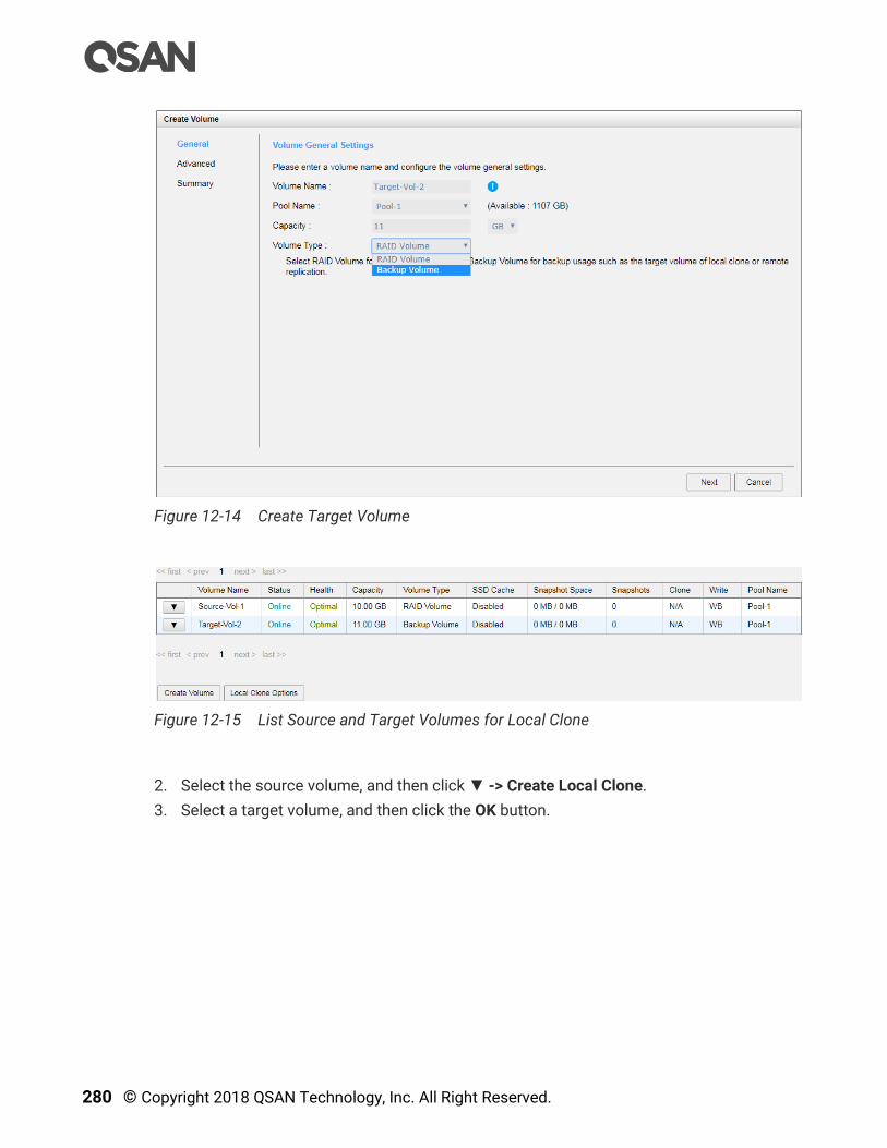
280 © Copyright 2018 QSAN Technology, Inc. All Right Reserved.
Figure 12-14 Create Target Volume
Figure 12-15 List Source and Target Volumes for Local Clone
2. Select the source volume, and then click ▼ -> Create Local Clone.
3. Select a target volume, and then click the OK button.

Data Backup 281
Figure 12-16 Create Local Clone
TIP:
The volume type of the target volume should be set as Backup Volume.
Please refer to the chapter 8.5.1, Create a Volume in the Storage
Management chapter.
4. At this time, if the source volume has no snapshot space, it will be allocated snapshot
space for clone usage automatically. The capacity will depend on the parameter of
Cloning Options.
5. Done, now ready to start cloning volumes.
Figure 12-17 List Source and Target Volumes
Start Local Clone Task
To start cloning, please follow the procedures.
1. Select the source volume, and then click ▼ -> Start Local Clone.
2. Click the OK button. The source volume will take a snapshot, and then start cloning.
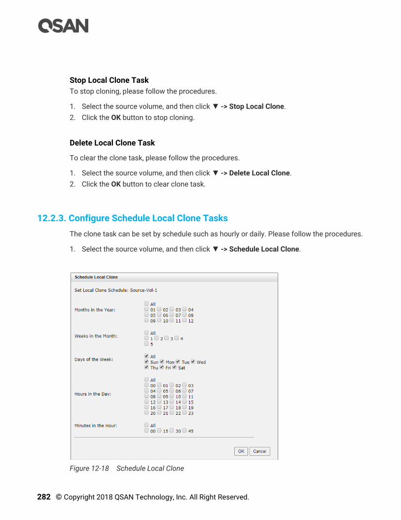
282 © Copyright 2018 QSAN Technology, Inc. All Right Reserved.
Stop Local Clone Task
To stop cloning, please follow the procedures.
1. Select the source volume, and then click ▼ -> Stop Local Clone.
2. Click the OK button to stop cloning.
Delete Local Clone Task
To clear the clone task, please follow the procedures.
1. Select the source volume, and then click ▼ -> Delete Local Clone.
2. Click the OK button to clear clone task.
12.2.3. Configure Schedule Local Clone Tasks
The clone task can be set by schedule such as hourly or daily. Please follow the procedures.
1. Select the source volume, and then click ▼ -> Schedule Local Clone.
Figure 12-18 Schedule Local Clone
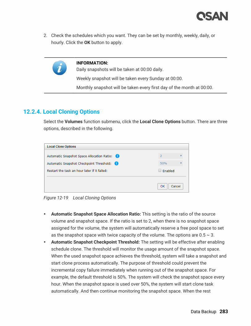
Data Backup 283
2. Check the schedules which you want. They can be set by monthly, weekly, daily, or
hourly. Click the OK button to apply.
INFORMATION:
Daily snapshots will be taken at 00:00 daily.
Weekly snapshot will be taken every Sunday at 00:00.
Monthly snapshot will be taken every first day of the month at 00:00.
12.2.4. Local Cloning Options
Select the Volumes function submenu, click the Local Clone Options button. There are three
options, described in the following.
Figure 12-19 Local Cloning Options
Automatic Snapshot Space Allocation Ratio: This setting is the ratio of the source
volume and snapshot space. If the ratio is set to 2, when there is no snapshot space
assigned for the volume, the system will automatically reserve a free pool space to set
as the snapshot space with twice capacity of the volume. The options are 0.5 ~ 3.
Automatic Snapshot Checkpoint Threshold: The setting will be effective after enabling
schedule clone. The threshold will monitor the usage amount of the snapshot space.
When the used snapshot space achieves the threshold, system will take a snapshot and
start clone process automatically. The purpose of threshold could prevent the
incremental copy failure immediately when running out of the snapshot space. For
example, the default threshold is 50%. The system will check the snapshot space every
hour. When the snapshot space is used over 50%, the system will start clone task
automatically. And then continue monitoring the snapshot space. When the rest

284 © Copyright 2018 QSAN Technology, Inc. All Right Reserved.
snapshot space has been used 50%, in other words, the total snapshot space has been
used 75%, the system will start clone task again.
Restart the task an hour later if failed The setting will be effective after enabling a
scheduled clone. When running out of snapshot space, the volume clone process will be
stopped because there is no more available snapshot space. If this option is checked,
the system will clear the snapshots of clone in order to release snapshot space
automatically, and the clone task will be restarted after an hour. This task will start a full
copy.
CAUTION:
The default snapshot space allocated by the system is two times the
capacity of source volume. That is the best value of our suggestion. If
user sets snapshot space manually and lower than the default value,
understand that if the snapshot space is not enough, the clone task will
fail.
12.2.5. Local Clone Notices
While the clone is processing manually, the incremental data of the volume is over the
snapshot space. The clone will complete the task, but the clone snapshot will fail. At the
next time, when trying to start clone, it will get a warning message “There is not enough of
snapshot space for the operation”. The user needs to clean up the snapshot space in order
to use the clone feature. Each time the clone snapshot failed, it means that the system
loses the reference value of incremental data. So it will need to make a full copy the next
time a clone task starts.
12.3. Managing Remote Replications
Remote replication is a block-level, asynchronous, differential remote volume backup
function through LAN or WAN. It has many powerful capabilities such as unlimited
bandwidth, traffic shaping, and multiple connections per replication task.
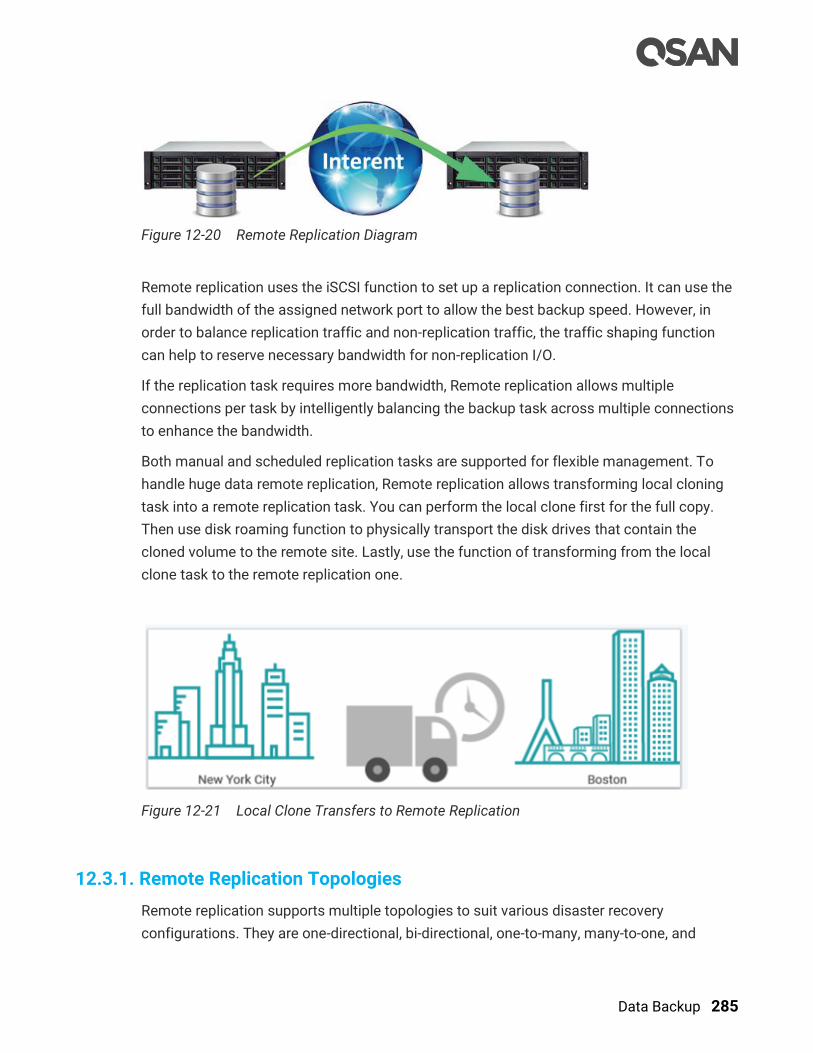
Data Backup 285
Figure 12-20 Remote Replication Diagram
Remote replication uses the iSCSI function to set up a replication connection. It can use the
full bandwidth of the assigned network port to allow the best backup speed. However, in
order to balance replication traffic and non-replication traffic, the traffic shaping function
can help to reserve necessary bandwidth for non-replication I/O.
If the replication task requires more bandwidth, Remote replication allows multiple
connections per task by intelligently balancing the backup task across multiple connections
to enhance the bandwidth.
Both manual and scheduled replication tasks are supported for flexible management. To
handle huge data remote replication, Remote replication allows transforming local cloning
task into a remote replication task. You can perform the local clone first for the full copy.
Then use disk roaming function to physically transport the disk drives that contain the
cloned volume to the remote site. Lastly, use the function of transforming from the local
clone task to the remote replication one.
Figure 12-21 Local Clone Transfers to Remote Replication
12.3.1. Remote Replication Topologies
Remote replication supports multiple topologies to suit various disaster recovery
configurations. They are one-directional, bi-directional, one-to-many, many-to-one, and
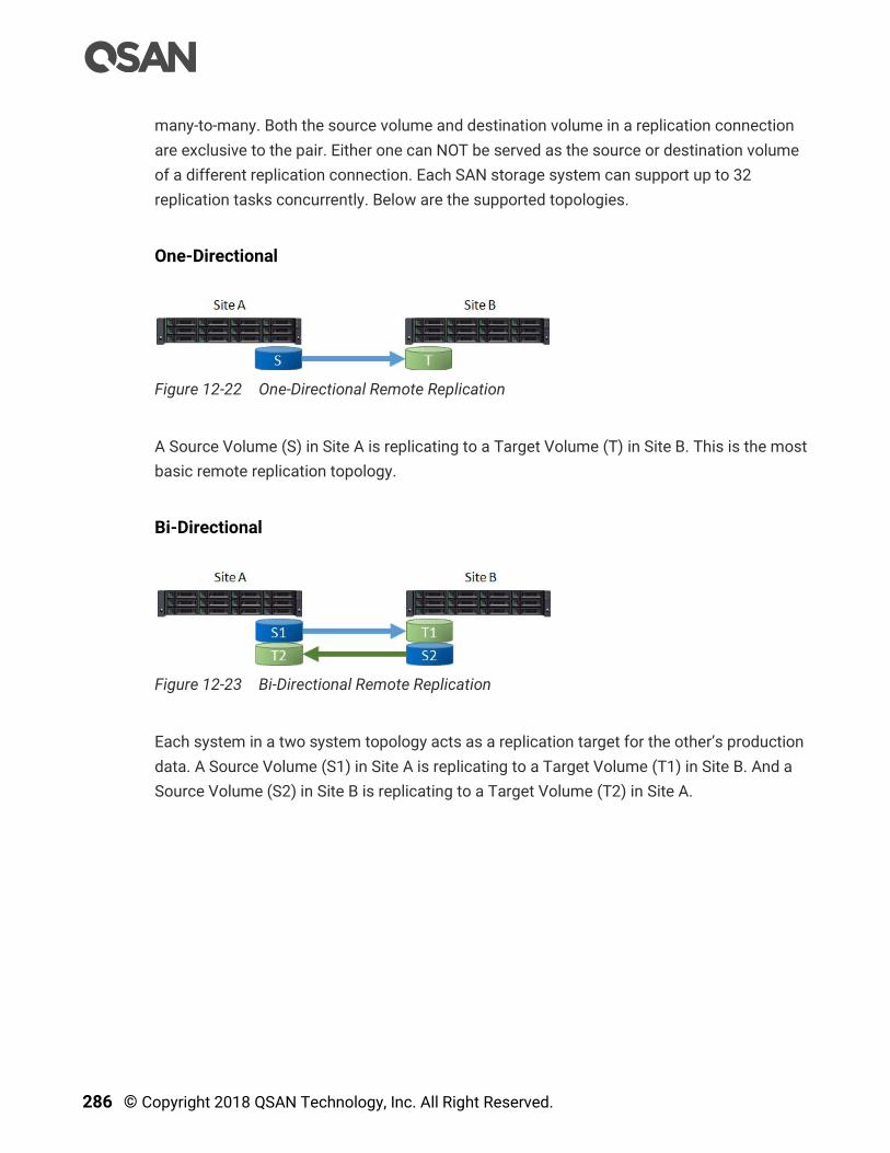
286 © Copyright 2018 QSAN Technology, Inc. All Right Reserved.
many-to-many. Both the source volume and destination volume in a replication connection
are exclusive to the pair. Either one can NOT be served as the source or destination volume
of a different replication connection. Each SAN storage system can support up to 32
replication tasks concurrently. Below are the supported topologies.
One-Directional
Figure 12-22 One-Directional Remote Replication
A Source Volume (S) in Site A is replicating to a Target Volume (T) in Site B. This is the most
basic remote replication topology.
Bi-Directional
Figure 12-23 Bi-Directional Remote Replication
Each system in a two system topology acts as a replication target for the other’s production
data. A Source Volume (S1) in Site A is replicating to a Target Volume (T1) in Site B. And a
Source Volume (S2) in Site B is replicating to a Target Volume (T2) in Site A.
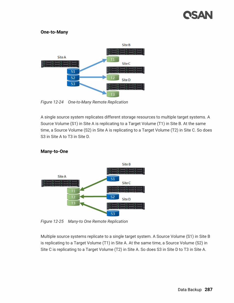
Data Backup 287
One-to-Many
Figure 12-24 One-to-Many Remote Replication
A single source system replicates different storage resources to multiple target systems. A
Source Volume (S1) in Site A is replicating to a Target Volume (T1) in Site B. At the same
time, a Source Volume (S2) in Site A is replicating to a Target Volume (T2) in Site C. So does
S3 in Site A to T3 in Site D.
Many-to-One
Figure 12-25 Many-to One Remote Replication
Multiple source systems replicate to a single target system. A Source Volume (S1) in Site B
is replicating to a Target Volume (T1) in Site A. At the same time, a Source Volume (S2) in
Site C is replicating to a Target Volume (T2) in Site A. So does S3 in Site D to T3 in Site A.
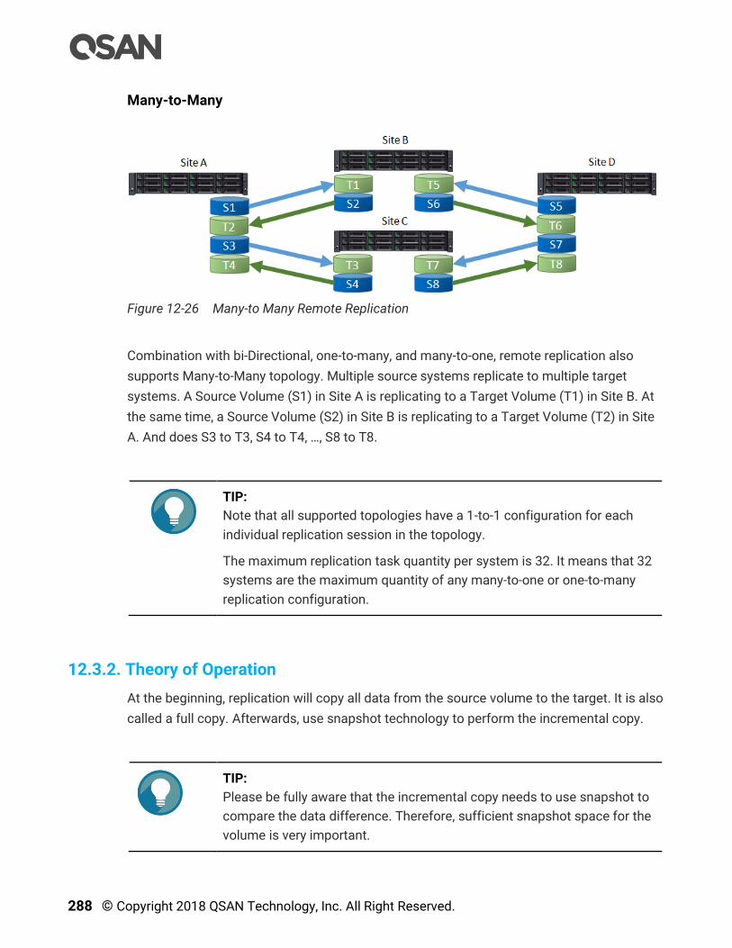
288 © Copyright 2018 QSAN Technology, Inc. All Right Reserved.
Many-to-Many
Figure 12-26 Many-to Many Remote Replication
Combination with bi-Directional, one-to-many, and many-to-one, remote replication also
supports Many-to-Many topology. Multiple source systems replicate to multiple target
systems. A Source Volume (S1) in Site A is replicating to a Target Volume (T1) in Site B. At
the same time, a Source Volume (S2) in Site B is replicating to a Target Volume (T2) in Site
A. And does S3 to T3, S4 to T4, …, S8 to T8.
TIP:
Note that all supported topologies have a 1-to-1 configuration for each
individual replication session in the topology.
The maximum replication task quantity per system is 32. It means that 32
systems are the maximum quantity of any many-to-one or one-to-many
replication configuration.
12.3.2. Theory of Operation
At the beginning, replication will copy all data from the source volume to the target. It is also
called a full copy. Afterwards, use snapshot technology to perform the incremental copy.
TIP:
Please be fully aware that the incremental copy needs to use snapshot to
compare the data difference. Therefore, sufficient snapshot space for the
volume is very important.
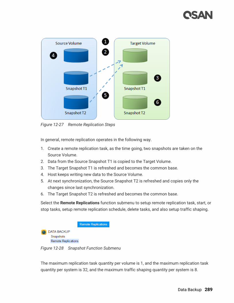
Data Backup 289
Figure 12-27 Remote Replication Steps
In general, remote replication operates in the following way.
1. Create a remote replication task, as the time going, two snapshots are taken on the
Source Volume.
2. Data from the Source Snapshot T1 is copied to the Target Volume.
3. The Target Snapshot T1 is refreshed and becomes the common base.
4. Host keeps writing new data to the Source Volume.
5. At next synchronization, the Source Snapshot T2 is refreshed and copies only the
changes since last synchronization.
6. The Target Snapshot T2 is refreshed and becomes the common base.
Select the Remote Replications function submenu to setup remote replication task, start, or
stop tasks, setup remote replication schedule, delete tasks, and also setup traffic shaping.
Figure 12-28 Snapshot Function Submenu
The maximum replication task quantity per volume is 1, and the maximum replication task
quantity per system is 32, and the maximum traffic shaping quantity per system is 8.

290 © Copyright 2018 QSAN Technology, Inc. All Right Reserved.
Table 12-4 Remote Replication Parameters
Item Value
Maximum remote replication task quantity per volume
(Maximum remote replication pairs per source volume) 1
Maximum remote replication task quantity per system 32
Maximum traffic shaping quantity per system 8
Maximum iSCSI multi-path quantity in a remote replication
task 2
Maximum iSCSI multiple connection quantity per remote
replication task path 4
12.3.3. Configure Remote Replication
Create a Remote Replication Task
Here’s an example of creating a remote replication task from source volume to target one.
Assume that we define the name and the IP addresses in the example.
Figure 12-29 Example of Creating a Remote Replication Task
Site A Source Unit Configuration:
Controller 1, Onboard LAN 1 IP Address: 10.10.1.1
Controller 1, Onboard LAN 2 IP Address: 10.10.1.2
Controller 2, Onboard LAN 1 IP Address: 10.10.1.3
Controller 2, Onboard LAN 2 IP Address: 10.10.1.4
Source Volume Name: Source-Vol-1
Site B Target Unit Configuration:
Controller 1, Onboard LAN 1 IP Address: 10.10.1.101
Controller 1, Onboard LAN 2 IP Address: 10.10.1.102
Controller 2, Onboard LAN 1 IP Address: 10.10.1.103
Controller 2, Onboard LAN 2 IP Address: 10.10.1.104
Target Volume: Name: Target-Vol-2

Data Backup 291
Operate SANOS web UI of Site B target unit:
1. Before replication, it must have a backup target volume. Select the Volumes function
submenu, click the Create Volume button. And then select Volume Type to Backup
Volume. Please refer to the chapter 8.5.1, Create a Volume section in the Storage
Management chapter.
Figure 12-30 Create Target Volume in Site B
2. After creating a target volume, please also setup snapshot space. So the snapshot of
the source volume can replicate to the target volume. Please refer to the chapter 12.1.2,
Configure Snapshot section.
Figure 12-31 List Target Volume in Site B
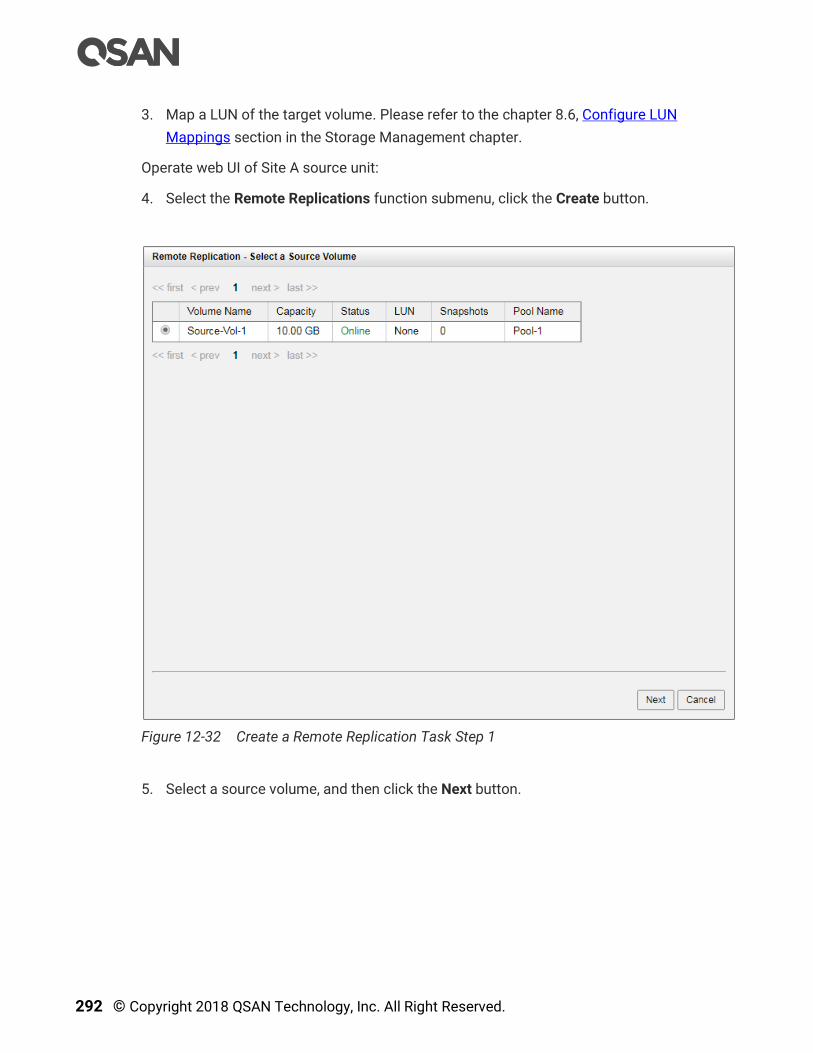
292 © Copyright 2018 QSAN Technology, Inc. All Right Reserved.
3. Map a LUN of the target volume. Please refer to the chapter 8.6, Configure LUN
Mappings section in the Storage Management chapter.
Operate web UI of Site A source unit:
4. Select the Remote Replications function submenu, click the Create button.
Figure 12-32 Create a Remote Replication Task Step 1
5. Select a source volume, and then click the Next button.
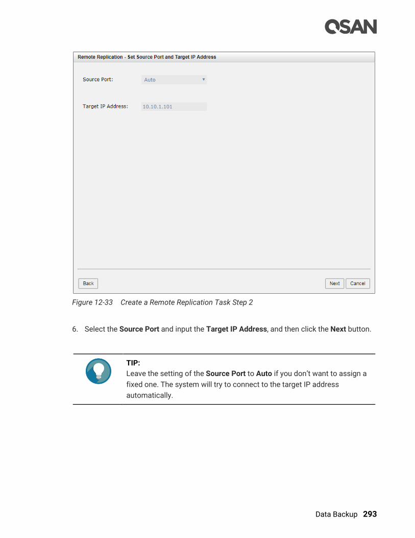
Data Backup 293
Figure 12-33 Create a Remote Replication Task Step 2
6. Select the Source Port and input the Target IP Address, and then click the Next button.
TIP:
Leave the setting of the Source Port to Auto if you don’t want to assign a
fixed one. The system will try to connect to the target IP address
automatically.

294 © Copyright 2018 QSAN Technology, Inc. All Right Reserved.
Figure 12-34 Create a Remote Replication Task Step 3
7. Select an Authentication Method and input the CHAP Username and CHAP Password if
needed. Select a Target Name, and then click the Next button.
TIP:
This CHAP account is the iSCSI authentication of the Site B target unit.
For more information about CHAP, please refer to the chapter 7.3.4,
Configure iSCSI CHAP Accounts section in the Host Configuration
chapter.
Select No Authentication Method if there is no CHAP enabling in the Site
B target unit.

Data Backup 295
Figure 12-35 Create a Remote Replication Task Step 4
8. Select a Target LUN in Site B target unit. Finally, click the Finish button.
Figure 12-36 Remote Replication Task is Created
9. The replication task is created. At this time, if the source volume has no snapshot space,
it will be allocated snapshot space for replication usage automatically. The size will
depend on the parameter of replication options.
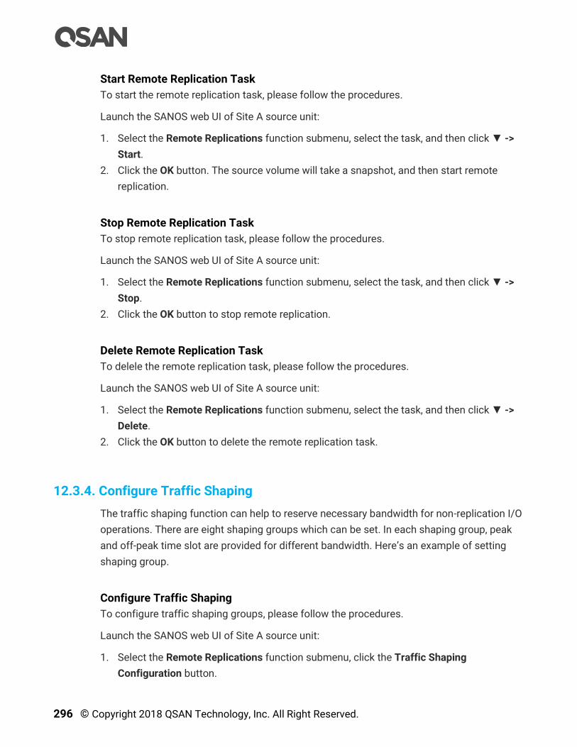
296 © Copyright 2018 QSAN Technology, Inc. All Right Reserved.
Start Remote Replication Task
To start the remote replication task, please follow the procedures.
Launch the SANOS web UI of Site A source unit:
1. Select the Remote Replications function submenu, select the task, and then click ▼ ->
Start.
2. Click the OK button. The source volume will take a snapshot, and then start remote
replication.
Stop Remote Replication Task
To stop remote replication task, please follow the procedures.
Launch the SANOS web UI of Site A source unit:
1. Select the Remote Replications function submenu, select the task, and then click ▼ ->
Stop.
2. Click the OK button to stop remote replication.
Delete Remote Replication Task
To delele the remote replication task, please follow the procedures.
Launch the SANOS web UI of Site A source unit:
1. Select the Remote Replications function submenu, select the task, and then click ▼ ->
Delete.
2. Click the OK button to delete the remote replication task.
12.3.4. Configure Traffic Shaping
The traffic shaping function can help to reserve necessary bandwidth for non-replication I/O
operations. There are eight shaping groups which can be set. In each shaping group, peak
and off-peak time slot are provided for different bandwidth. Here’s an example of setting
shaping group.
Configure Traffic Shaping
To configure traffic shaping groups, please follow the procedures.
Launch the SANOS web UI of Site A source unit:
1. Select the Remote Replications function submenu, click the Traffic Shaping
Configuration button.
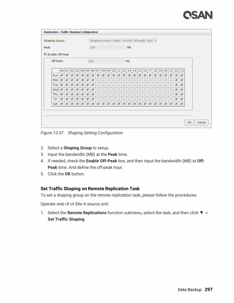
Data Backup 297
Figure 12-37 Shaping Setting Configuration
2. Select a Shaping Group to setup.
3. Input the bandwidth (MB) at the Peak time.
4. If needed, check the Enable Off-Peak box, and then input the bandwidth (MB) at Off-
Peak time. And define the off-peak hour.
5. Click the OK button.
Set Traffic Shaping on Remote Replication Task
To set a shaping group on the remote replication task, please follow the procedures.
Operate web UI of Site A source unit:
1. Select the Remote Replications function submenu, select the task, and then click ▼ ->
Set Traffic Shaping.
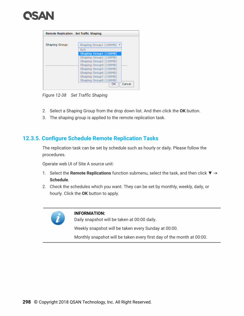
298 © Copyright 2018 QSAN Technology, Inc. All Right Reserved.
Figure 12-38 Set Traffic Shaping
2. Select a Shaping Group from the drop down list. And then click the OK button.
3. The shaping group is applied to the remote replication task.
12.3.5. Configure Schedule Remote Replication Tasks
The replication task can be set by schedule such as hourly or daily. Please follow the
procedures.
Operate web UI of Site A source unit:
1. Select the Remote Replications function submenu, select the task, and then click ▼ ->
Schedule.
2. Check the schedules which you want. They can be set by monthly, weekly, daily, or
hourly. Click the OK button to apply.
INFORMATION:
Daily snapshot will be taken at 00:00 daily.
Weekly snapshot will be taken every Sunday at 00:00.
Monthly snapshot will be taken every first day of the month at 00:00.
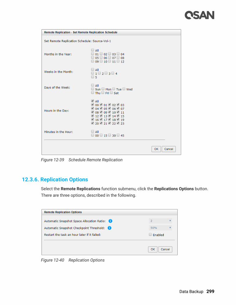
Data Backup 299
Figure 12-39 Schedule Remote Replication
12.3.6. Replication Options
Select the Remote Replications function submenu, click the Replications Options button.
There are three options, described in the following.
Figure 12-40 Replication Options
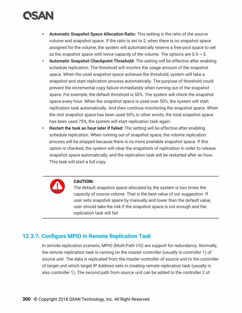
300 © Copyright 2018 QSAN Technology, Inc. All Right Reserved.
Automatic Snapshot Space Allocation Ratio: This setting is the ratio of the source
volume and snapshot space. If the ratio is set to 2, when there is no snapshot space
assigned for the volume, the system will automatically reserve a free pool space to set
as the snapshot space with twice capacity of the volume. The options are 0.5 ~ 3.
Automatic Snapshot Checkpoint Threshold: The setting will be effective after enabling
schedule replication. The threshold will monitor the usage amount of the snapshot
space. When the used snapshot space achieves the threshold, system will take a
snapshot and start replication process automatically. The purpose of threshold could
prevent the incremental copy failure immediately when running out of the snapshot
space. For example, the default threshold is 50%. The system will check the snapshot
space every hour. When the snapshot space is used over 50%, the system will start
replication task automatically. And then continue monitoring the snapshot space. When
the rest snapshot space has been used 50%, in other words, the total snapshot space
has been used 75%, the system will start replication task again.
Restart the task an hour later if failed: The setting will be effective after enabling
schedule replication. When running out of snapshot space, the volume replication
process will be stopped because there is no more available snapshot space. If this
option is checked, the system will clear the snapshots of replication in order to release
snapshot space automatically, and the replication task will be restarted after an hour.
This task will start a full copy.
CAUTION:
The default snapshot space allocated by the system is two times the
capacity of source volume. That is the best value of our suggestion. If
user sets snapshot space by manually and lower than the default value,
user should take the risk if the snapshot space is not enough and the
replication task will fail.
12.3.7. Configure MPIO in Remote Replication Task
In remote replication scenario, MPIO (Multi-Path I/O) are support for redundancy. Normally,
the remote replication task is running on the master controller (usually is controller 1) of
source unit. The data is replicated from the master controller of source unit to the controller
of target unit which target IP Address sets in creating remote replication task (usually is
also controller 1). The second path from source unit can be added to the controller 2 of

Data Backup 301
target unit. The maximum MPIO in remote replication task is 2 paths. The following is the
remote replication MPIO diagram.
Figure 12-41 Remote Replication MPIO Diagram
How Redundancy Works with Remote Replication
If controller 1 fails on the source unit, the replication connection will be taken over by
controller 2 and the replication task will continue running.
Figure 12-42 Remote Replication Source Controller Fail Diagram
In another scenario, when controller1 fails on the target unit, the replication connection will
be failed over to the second path from the controller 1 of the source unit to controller 2 of
target unit.

302 © Copyright 2018 QSAN Technology, Inc. All Right Reserved.
Figure 12-43 Remote Replication Target Controller Fail Diagram
Add Multipath in Remote Replication Task
Here’s an example of adding the second path in the remote replication. Assume that we
define the IP addresses in the example.
Site A Source Unit Configuration:
Controller 1, Onboard LAN 1 IP Address: 10.10.1.1
Controller 1, Onboard LAN 2 IP Address: 10.10.1.2
Controller 2, Onboard LAN 1 IP Address: 10.10.1.3
Controller 2, Onboard LAN 2 IP Address: 10.10.1.4
Source Volume Name: Source-Vol-1
Site B Target Unit Configuration:
Controller 1, Onboard LAN 1 IP Address: 10.10.1.101
Controller 1, Onboard LAN 2 IP Address: 10.10.1.102
Controller 2, Onboard LAN 1 IP Address: 10.10.1.103
Controller 2, Onboard LAN 2 IP Address: 10.10.1.104
Target Volume: Name: Target-Vol-2
Operate web UI of Site A source unit:
1. Select the Remote Replications function submenu, select the task, and then click ▼ ->
Add Multipath.

Data Backup 303
Figure 12-44 Add Multipath in Remote Replication Step 1
2. Select the Source Port and input the Target IP Address, and then click the Next button.
TIP:
Leave the setting of Source Port to Auto if you don’t want to assign. The
system will try to connect to the target IP address automatically.
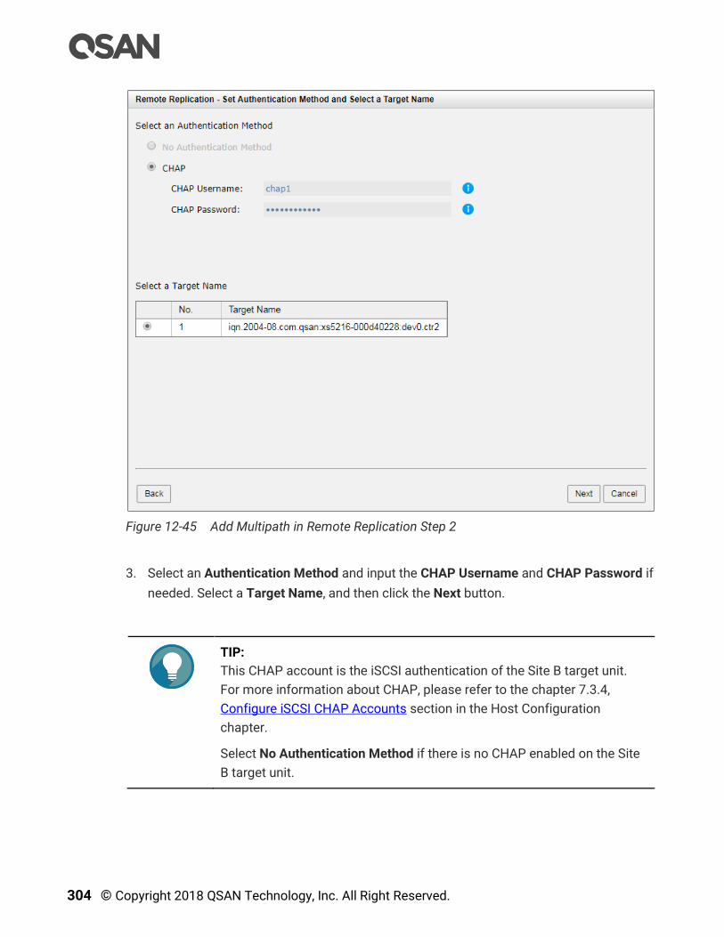
304 © Copyright 2018 QSAN Technology, Inc. All Right Reserved.
Figure 12-45 Add Multipath in Remote Replication Step 2
3. Select an Authentication Method and input the CHAP Username and CHAP Password if
needed. Select a Target Name, and then click the Next button.
TIP:
This CHAP account is the iSCSI authentication of the Site B target unit.
For more information about CHAP, please refer to the chapter 7.3.4,
Configure iSCSI CHAP Accounts section in the Host Configuration
chapter.
Select No Authentication Method if there is no CHAP enabled on the Site
B target unit.

Data Backup 305
Figure 12-46 Add Multipath in Remote Replication Step 3
4. Select a Target LUN in Site B target unit. Finally, click Finish button.
Figure 12-47 List Multipath in Remote Replication Task

306 © Copyright 2018 QSAN Technology, Inc. All Right Reserved.
5. The second path in remote replication task is added.
Delete Multipath in Remote Replication Task
To delete multi path of the replication task, please follow the procedures.
Operate web UI of Site A source unit:
1. Select the Remote Replications function submenu, select the task path, and then click
▼ -> Delete Path.
2. Click the OK button to delete the path.
12.3.8. Configure MC/S in Remote Replication Task Path
MC/S (Multiple Connections per Session) is another feature in remote replication. If there
are more than one iSCSI ports available on source unit, and they can connect to the other
iSCSI ports of the target unit, MC/S can be added for increasing the replicating speed. The
maximum MC/S per task path is 4 connections.
Add Connections in Remote Replication Task Path
Here’s an example of adding the second connection in the remote replication task. Assume
that we define the IP addresses in the example.
Site A Source Unit Configuration:
Controller 1, Onboard LAN 1 IP Address: 10.10.1.1
Controller 1, Onboard LAN 2 IP Address: 10.10.1.2
Controller 2, Onboard LAN 1 IP Address: 10.10.1.3
Controller 2, Onboard LAN 2 IP Address: 10.10.1.4
Source Volume Name: Source-Vol-1
Site B Target Unit Configuration:
Controller 1, Onboard LAN 1 IP Address: 10.10.1.101
Controller 1, Onboard LAN 2 IP Address: 10.10.1.102
Controller 2, Onboard LAN 1 IP Address: 10.10.1.103
Controller 2, Onboard LAN 2 IP Address: 10.10.1.104
Target Volume: Name: Target-Vol-2
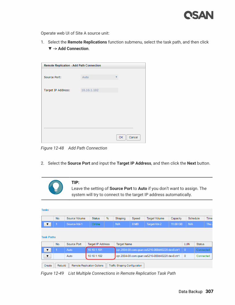
Data Backup 307
Operate web UI of Site A source unit:
1. Select the Remote Replications function submenu, select the task path, and then click
▼ -> Add Connection.
Figure 12-48 Add Path Connection
2. Select the Source Port and input the Target IP Address, and then click the Next button.
TIP:
Leave the setting of Source Port to Auto if you don’t want to assign. The
system will try to connect to the target IP address automatically.
Figure 12-49 List Multiple Connections in Remote Replication Task Path

308 © Copyright 2018 QSAN Technology, Inc. All Right Reserved.
3. The second connection in remote replication task path is added. If necessary, click ▼ ->
Add Connection to add another.
Delete Connections in Remote Replication Task Path
To delete multi connections per session of the replication task path, please follow the
procedures.
1. Operate Site A source unit. Select the Remote Replications function submenu, select the
task path, and then click ▼ -> Delete Connection.
Figure 12-50 Delete Path Connection
2. Select the connection(s) which want to be deleted, and then click the OK button.
3. The multiple connection(s) are deleted.
TIP:
When deleting multiple connections, note that at least one connection
must remain.

Data Backup 309
12.3.9. Local Clone Transfers to Remote Replication
It is always being a problem that to do full copy over LAN or WAN when the replication task
is executed at the first time. It may take days or weeks to replicate data from source to
target within limited network bandwidth. We provide two methods to help users shorten the
time of executing a full copy.
1. One is to skip full copy on a new, clean volume. The term “clean” means that the volume
has never been written data since created. For a new created volume which has not
been accessed, the system will recognize it and skip full copy automatically when the
remote replication task is created on this volume at the first time.
TIP:
Any I/O access to the new created volume will make it as “not clean”, even
though executing “Erase” function when a volume is created. The full copy
will take place in such a case.
2. The other way is to use local volume clone function, which is a local data copy function
between volumes to execute full copy at the first time. Then carry all the physical disk
drives of the target volume and move to the target unit. Finally, turn the local clone task
into remote replication task with differential copy afterward.
Figure 12-51 Local Clone Transfers to Remote Replication Diagram

310 © Copyright 2018 QSAN Technology, Inc. All Right Reserved.
To do that volume disk local clone transfers to remote replication, please follow the
procedures.
Launch SANOS web UI of Site A source unit:
1. Select the Volumes function submenu, select a source volume, and click ▼ -> Create
Local Clone to create a local clone task. For more information about local clone, please
refer to the chapter 12.2.2, Configure Local Clone section.
2. Click ▼ -> Start Local Clone to execute full copy the data from source volume to target
one.
3. Click ▼ -> Covert to Remote Replication to change the local clone task to a remote
replication task.
Figure 12-52 List Source and Target Volumes for Local Clone
4. The Clone column of the source volume will be changed from the name of the target
volume into QRep.
CAUTION:
Converting a local clone task to a remote replication one is only available
when the clone task has been finished. This change is irreversible.
5. Select the Pools function submenu, select the pool, and click ▼ -> Deactive.
6. Plug out all the physical disk drives, and carry them to Site B, plug them into the target
unit.
Operate web UI of Site B target unit:
7. Select the Pools function submenu, select the pool, and click ▼ -> Active.
8. Select the Volumes function submenu, please setup snapshot space. So the snapshot
of the source volume can replicate to the target volume. Please refer to the chapter
12.1.2, Configure Snapshot section.

Data Backup 311
9. Map a LUN of the target volume. Please refer to the chapter 8.6, Configure LUN
Mappings section in the Storage Management chapter.
Launch SANOS web UI of Site A source unit:
10. Select the Remote Replications function submenu, click the Rebuild button to rebuild
the remote replication task which is changed from a clone task formerly.
Figure 12-53 Rebuild Clone Relationship Step 1
11. Select a source volume, and then click the Next button.

312 © Copyright 2018 QSAN Technology, Inc. All Right Reserved.
Figure 12-54 Rebuild Clone Relationship Step 2
12. Select the Source Port and input the Target IP Address, and then click the Next button.
TIP:
Leave the setting of Source Port to Auto if you don’t want to assign a
fixed one. The system will try to connect to the target IP address
automatically.
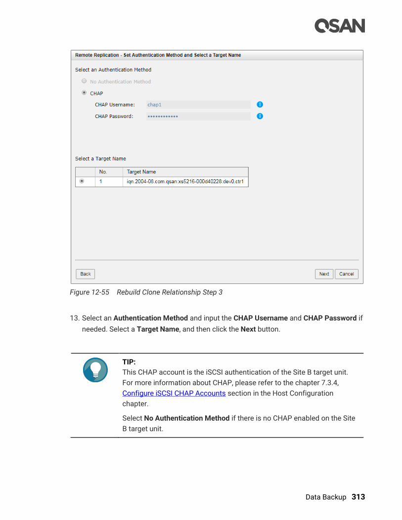
Data Backup 313
Figure 12-55 Rebuild Clone Relationship Step 3
13. Select an Authentication Method and input the CHAP Username and CHAP Password if
needed. Select a Target Name, and then click the Next button.
TIP:
This CHAP account is the iSCSI authentication of the Site B target unit.
For more information about CHAP, please refer to the chapter 7.3.4,
Configure iSCSI CHAP Accounts section in the Host Configuration
chapter.
Select No Authentication Method if there is no CHAP enabled on the Site
B target unit.
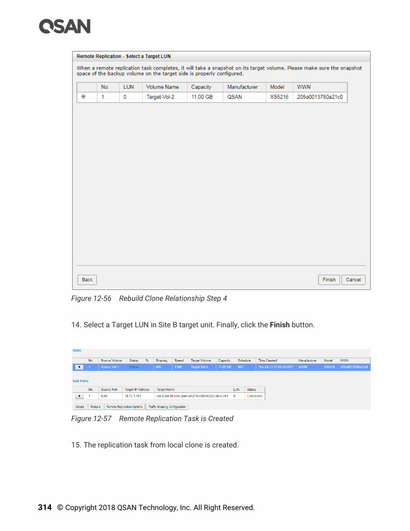
314 © Copyright 2018 QSAN Technology, Inc. All Right Reserved.
Figure 12-56 Rebuild Clone Relationship Step 4
14. Select a Target LUN in Site B target unit. Finally, click the Finish button.
Figure 12-57 Remote Replication Task is Created
15. The replication task from local clone is created.
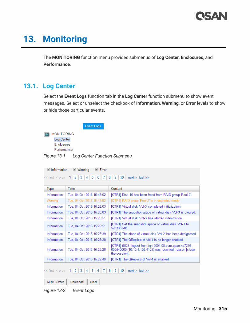
Monitoring 315
13. Monitoring
The MONITORING function menu provides submenus of Log Center, Enclosures, and
Performance.
13.1. Log Center
Select the Event Logs function tab in the Log Center function submenu to show event
messages. Select or unselect the checkbox of Information, Warning, or Error levels to show
or hide those particular events.
Figure 13-1 Log Center Function Submenu
Figure 13-2 Event Logs
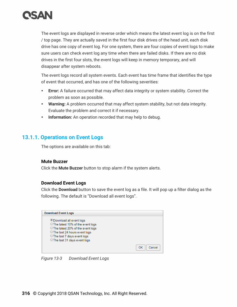
316 © Copyright 2018 QSAN Technology, Inc. All Right Reserved.
The event logs are displayed in reverse order which means the latest event log is on the first
/ top page. They are actually saved in the first four disk drives of the head unit, each disk
drive has one copy of event log. For one system, there are four copies of event logs to make
sure users can check event log any time when there are failed disks. If there are no disk
drives in the first four slots, the event logs will keep in memory temporary, and will
disappear after system reboots.
The event logs record all system events. Each event has time frame that identifies the type
of event that occurred, and has one of the following severities:
Error: A failure occurred that may affect data integrity or system stability. Correct the
problem as soon as possible.
Warning: A problem occurred that may affect system stability, but not data integrity.
Evaluate the problem and correct it if necessary.
Information: An operation recorded that may help to debug.
13.1.1. Operations on Event Logs
The options are available on this tab:
Mute Buzzer
Click the Mute Buzzer button to stop alarm if the system alerts.
Download Event Logs
Click the Download button to save the event log as a file. It will pop up a filter dialog as the
following. The default is “Download all event logs”.
Figure 13-3 Download Event Logs

Monitoring 317
Clear Event Logs
Click the Clear button to clear all event logs.
TIP:
Please plug-in any of the first four hard drives, then event logs can be
saved and displayed in next system boot up. Otherwise, the event logs
cannot be saved.
13.2. Monitoring Enclosures
The Enclosures function submenu provides Hardware Monitoring and SES tabs to show
and monitor enclosure information.
Figure 13-4 Enclosure Function Submenu
13.2.1. Hardware Monitoring
Select the Hardware Monitoring function tab in the Enclosures function submenu shows the
information of current voltages, temperatures, status of power supply’s, and fan modules.

318 © Copyright 2018 QSAN Technology, Inc. All Right Reserved.
Figure 13-5 Hardware Monitoring

Monitoring 319
Monitoring Notifications
The status of the voltage and temperature are Good if their values are between Low
Warning and High Warning. If the value is lower than Low Warning or higher than High
Warning, the system will send a warning event log. If it is lower than Low Critical or higher
than High Critical, an error event log will be sent.
TIP:
For better protection and avoiding a single short period of abnormal
voltage or temperature, its recommend to enable Auto Shutdown setting
which could trigger an automatic shutdown. This is done using several
sensors placed on key systems that the system checks every 30 seconds
for present voltages or temperatures. The following items are trigger
conditions.
The value of voltage or temperature is lower than Low Critical or
higher than High Critical.
When one of these sensors reports above the threshold for three
contiguous minutes, the system will be shutdown automatically.
For more information about auto shutdown, please refer to the chapter
6.3.1, Boot Management Settings section in the System Settings chapter.
Fan Module Mechanism
Fan speed will adjust automatically according to system thermal and the status of power
and fan. For more information, please refer to the chapter 2.6, Fan Module and the chapter
6.3, Removing / Installing the Fan Module in the XCubeSAN Hardware Owner’s Manual.
13.2.2. Configuring SES
SES (SCSI Enclosure Services) is an enclosure management standard. The host can
communicate with the enclosure using a LUN and a specialized set of SCSI commands to
monitor hardware characteristics. Select SES function tab in Enclosure function submenu to
enable or disable the management of SES. Enable SES will map an iSCSI LUN or a FC LUN.
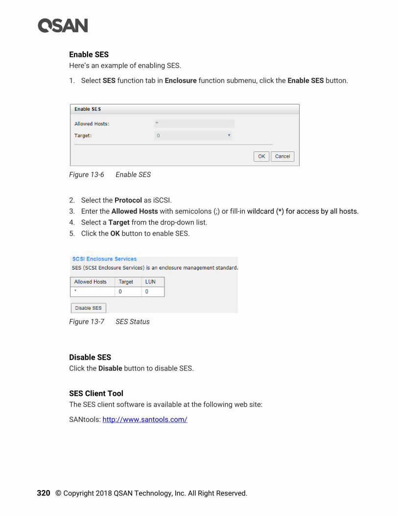
320 © Copyright 2018 QSAN Technology, Inc. All Right Reserved.
Enable SES
Here’s an example of enabling SES.
1. Select SES function tab in Enclosure function submenu, click the Enable SES button.
Figure 13-6 Enable SES
2. Select the Protocol as iSCSI.
3. Enter the Allowed Hosts with semicolons (;) or fill-in wildcard (*) for access by all hosts.
4. Select a Target from the drop-down list.
5. Click the OK button to enable SES.
Figure 13-7 SES Status
Disable SES
Click the Disable button to disable SES.
SES Client Tool
The SES client software is available at the following web site:
SANtools: http://www.santools.com/
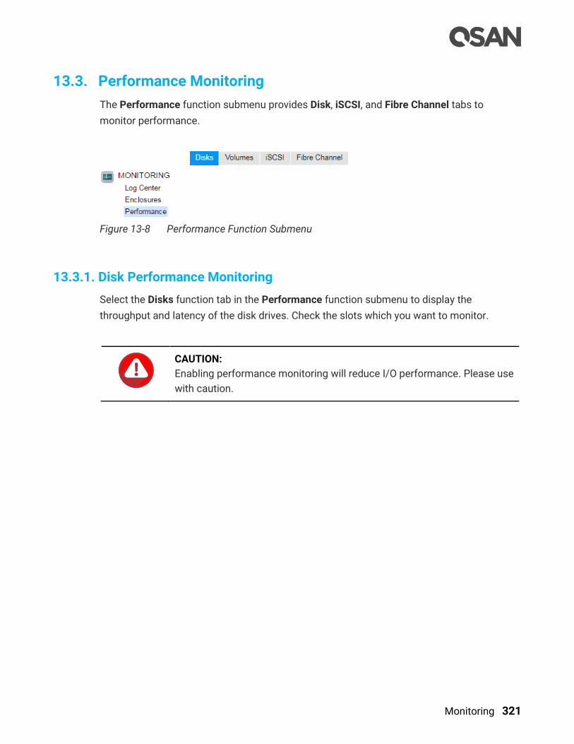
Monitoring 321
13.3. Performance Monitoring
The Performance function submenu provides Disk, iSCSI, and Fibre Channel tabs to
monitor performance.
Figure 13-8 Performance Function Submenu
13.3.1. Disk Performance Monitoring
Select the Disks function tab in the Performance function submenu to display the
throughput and latency of the disk drives. Check the slots which you want to monitor.
CAUTION:
Enabling performance monitoring will reduce I/O performance. Please use
with caution.

322 © Copyright 2018 QSAN Technology, Inc. All Right Reserved.
Figure 13-9 Disk Performance Monitoring
13.3.2. Volume Performance Monitoring
Select the Volume function tab in the Performance function submenu to display throughput
and IOPS of volumes. Each time you can monitor 10 volumes. Note that enabling
performance monitoring may impact I/O performance. Please click the Select Volumes
button to select the volumes for performance monitoring.

Monitoring 323
Figure 13-10 Select Volumes to Monitor
Please check the volumes to enable performance monitoring.
Figure 13-11 Volume Performance Monitoring

324 © Copyright 2018 QSAN Technology, Inc. All Right Reserved.
13.3.3. iSCSI Port Performance Monitoring
Select the iSCSI function tab in the Performance function submenu to display TX
(Transmission) and RX (Reception) of the iSCSI ports. Check the interfaces which you want
to monitor.
Figure 13-12 iSCSI Performance Monitoring
13.3.4. Fibre Channel Port Monitoring
Select the Fibre Channel function tab in the Performance function submenu display TX
(Transmission) and RX (Reception) of the fibre channels. Check the interfaces which you
want to monitor.

SED and ISE Support 325
14. SED and ISE Support
With data security issues at the time, the company places a high priority on ensuring that
sensitive data is protected from unauthorized access. Whether it is due to internal policies
or external compliance, access to data remains a matter of high importance for all
organizations. These organizations will seek out storage manufacturers that provide a
stored data protection method, SED (Self-Encrypting Drive), that has both authentication and
encryption features.
In addition, ISE (Instant Secure Erase) drive is designed to protect data on hard disk drives
by instantly resetting the drive back to factory settings and changing the encryption key so
that any data remaining on the drive is cryptographically erased. This means all data on the
drive is permanently and instantly unreadable, as needed.
INFORMATION:
SED (Self-Encryption Drive) and ISE (Instant Secure Erase) drive support is
available in SANOS firmware 1.3.0.
14.1. Overview
When disk drives are retired and moved outside from the data center into someone else’s
hands, the data on those drives is put at significant risk. IT administrators routinely retire
drives for a variety of reasons, including:
Returning drives for warranty, repair, maintenance, or expired lease agreements
Removal and disposal of disk drives
Repurposing drives to another storage
Through the study found that almost all drives eventually leave the enterprise or data center,
but the corporate data resides on such drives, and when most leave the data center, the
data they contain is still readable. Even data that has been striped across many drives in a
RAID protection is vulnerable to data theft, because just a typical single stripe in today’s
high-capacity arrays is large enough to expose the sensitive and secured data.

326 © Copyright 2018 QSAN Technology, Inc. All Right Reserved.
Drive Control Challenges and Disposal Costs
In an effort to avoid data breaches, corporations have tried many ways to erase the data on
retired drives before they leave the houses and potentially fall into the bad guy. Current
retirement practices are all expensive and time-consuming, such as:
Overwriting drive data
Degaussing or physically shredding
Hire professional disposal services
These designed to make data unreadable rely on significant human involvement in the
process, and are thus subject to both technical and human failure.
The Solution
Every day, thousands of disk drives leave data centers as old systems are retired. But what
if all those disk drives had been automatically and transparently encrypting that data,
enabling it to be instantly and securely erased? SED comprehensively resolve these issues,
making encryption for drive retirement both easy and affordable.
SED has build-in an encryption controller and an encryption key on the disk drive itself. It can
provide instant secure erase (cryptographic erase or making the data no longer readable),
and to enable auto-locking to secure active data if a drive is misplaced or stolen from a
system while in use.
While ISE provides instant secure erase only. When it’s time to retire or repurpose the drive,
the owner sends a command to the drive to perform a cryptographic erase. Cryptographic
erase simply replaces the encryption key inside the encrypted drive, making it impossible to
ever decrypt the data encrypted with the deleted key.
Benefits
SED & ISE reduce IT operating expenses by freeing IT from both drive control headaches
and disposal costs. By using SED & ISE, they are without hindering IT efficiency.
Furthermore, SED & ISE simplify decommissioning and preserve hardware value for returns
and repurposing by:
Securing warranty and expired lease returns
Eliminating the need to overwrite or destroy the drive
Enabling drives to be repurposed securely
In addition, the drive owner may choose to employ the SED in the auto-lock mode to help
secure active data against theft. Utilizing the SED in auto-lock mode simply requires
securing the drive during its normal use with an authentication key. When secured in this
SED and ISE Support 327
manner, the drive’s data encryption key is locked whenever the drive is powered down. In
other words, the moment the SED is switched off or unplugged, it automatically locks down
the drive’s data.
When the SED is then powered back on, the SED requires authentication before being able to
unlock its encryption key and read any data on the drive, thus protecting against
misplacement and insider or external theft.
14.2. Theory of Operation
SED has two functions. There are authentication which is operated by AK (Authentication
Key) and encryption data which is operated by DEK (Data Encryption Key). ISE drive has
encryption data only by DEK but no authentication.
14.2.1. SED Operation Process
An AK is generated by a user entered password. After enabling authentication key
successfully, recommend to export the key file to an external media (e.g.: external disk drive,
USB drive, etc.) and store it in a safe location. You must be able to use the authentication
key file to recover in case of an unforeseen event.
TIP:
Recommend backup the key, or you risk losing all data on the SEDs.
A new clean SED is not locked; it has to be written an AK into the SED first. It’s called initiate
SED. The following describes the steps that occur during the authentication process of a
secured drive.
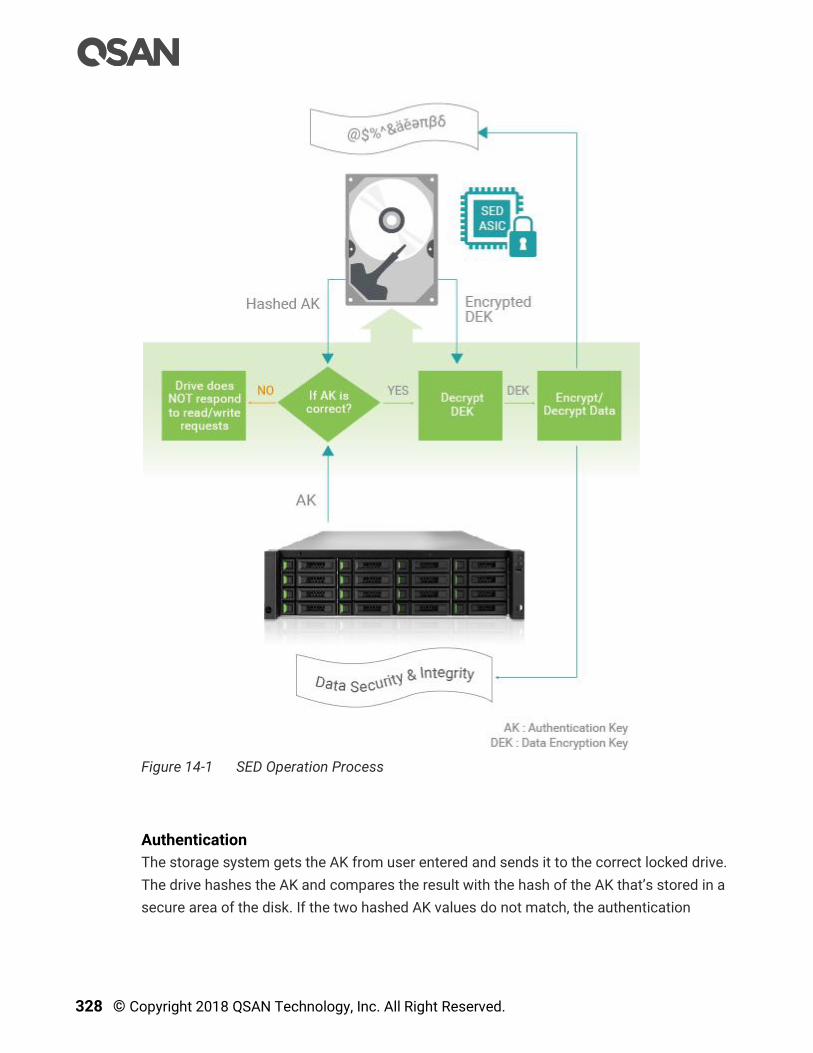
328 © Copyright 2018 QSAN Technology, Inc. All Right Reserved.
Figure 14-1 SED Operation Process
Authentication
The storage system gets the AK from user entered and sends it to the correct locked drive.
The drive hashes the AK and compares the result with the hash of the AK that’s stored in a
secure area of the disk. If the two hashed AK values do not match, the authentication
SED and ISE Support 329
process ends, and the drive will not permit reading data from the disk. The drive remains
locked.
Decrypt the DEK
If the two hashes match, the drive is then unlocked, and the drive uses the AK it received
from the storage system to decrypt the DEK (which was previously encrypted with the AK)
that’s stored in a secure area of the disk. Once the authentication process is successfully
completed, the drive is unlocked until the next time it is powered down. Note that this
authentication process only occurs when the drive is first powered on. It does not repeat
with each I/O.
The DEK Encrypts and Decrypts the Data
The DEK is then used to encrypt data to be written to the disk and to decrypt data that’s
being read from the disk. The drive now works in standard fashion during data transfers,
with encryption and decryption transparently occurring in the background.
14.2.2. ISE Technology
Each ISE drive (SED as well) randomly generates an encryption key in the factory that is
embedded on the drive. The ISE automatically performs full disk encryption; when a write is
performed; clear text enters the drive and is first encrypted (using the DEK embedded within
the drive) before being written to the disk. When a read is performed, the encrypted data on
the disk is decrypted before leaving the drive. During normal operation an ISE is completely
transparent to the system, appearing to be the same as a non-encrypting drive. The self-
encrypting is constantly encrypting, encryption cannot be accidentally turned off.

330 © Copyright 2018 QSAN Technology, Inc. All Right Reserved.
Figure 14-2 ISE Technology
ISE technology greatly simplifies repurposing of the drive and disposal. An owner wishing to
repurpose a drive simply performs a key erase to replace the encryption key. The drive
deletes the encryption key and replaces it with a new encryption key generated randomly
within the drive. After key erase, any data that had been written to the disk is unreadable;
data that was encrypted with the previous key is unintelligible when decrypted with the new
encryption key. The drive is left as it was delivered from the factory.
Instant Erase Limitation
If ISEs are free and not be used as any pool member, they can be performed instant erase.
The same limitation as SEDs, however SEDs can be erased by the AK is enabled. Another
case is that the unknown SED is put in lock mode, the way to erase it is to perform erase
SED by PSID which is a unique number in each drive, printed on the disk label, and visible to
anyone with physical access to the SED. The owner would simply perform a secure erase to
replace the encryption key.

SED and ISE Support 331
TIP:
SEDs or ISE drives can be erased only if their usage status is free.
14.3. Configure Authentication Key
This section will describe the operations of configuring AK.
Figure 14-3 Disk Encryption Function Submenu
14.3.1. Operations on Authentication Key
The options available in this tab:
Enable Authentication Key
Before using SED, you have to enable AK. Note that all SEDs in the system use this AK. Here
is an example of enabling an AK.
1. Select the Authentication Key function tab in the Disk Encryption function submenu.
Figure 14-4 Authentication Key is Disabled
2. Click the Enable Authentication Key button to enable.
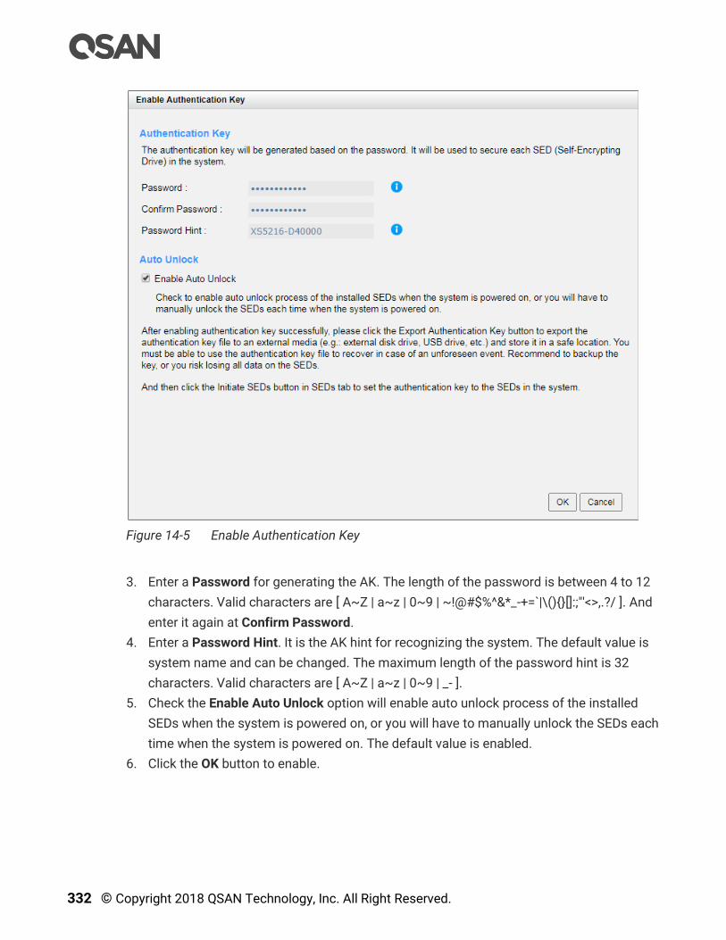
332 © Copyright 2018 QSAN Technology, Inc. All Right Reserved.
Figure 14-5 Enable Authentication Key
3. Enter a Password for generating the AK. The length of the password is between 4 to 12
characters. Valid characters are [ A~Z | a~z | 0~9 | ~!@#$%^&*_-+=`|\(){}[]:;"'<>,.?/ ]. And
enter it again at Confirm Password.
4. Enter a Password Hint. It is the AK hint for recognizing the system. The default value is
system name and can be changed. The maximum length of the password hint is 32
characters. Valid characters are [ A~Z | a~z | 0~9 | _- ].
5. Check the Enable Auto Unlock option will enable auto unlock process of the installed
SEDs when the system is powered on, or you will have to manually unlock the SEDs each
time when the system is powered on. The default value is enabled.
6. Click the OK button to enable.
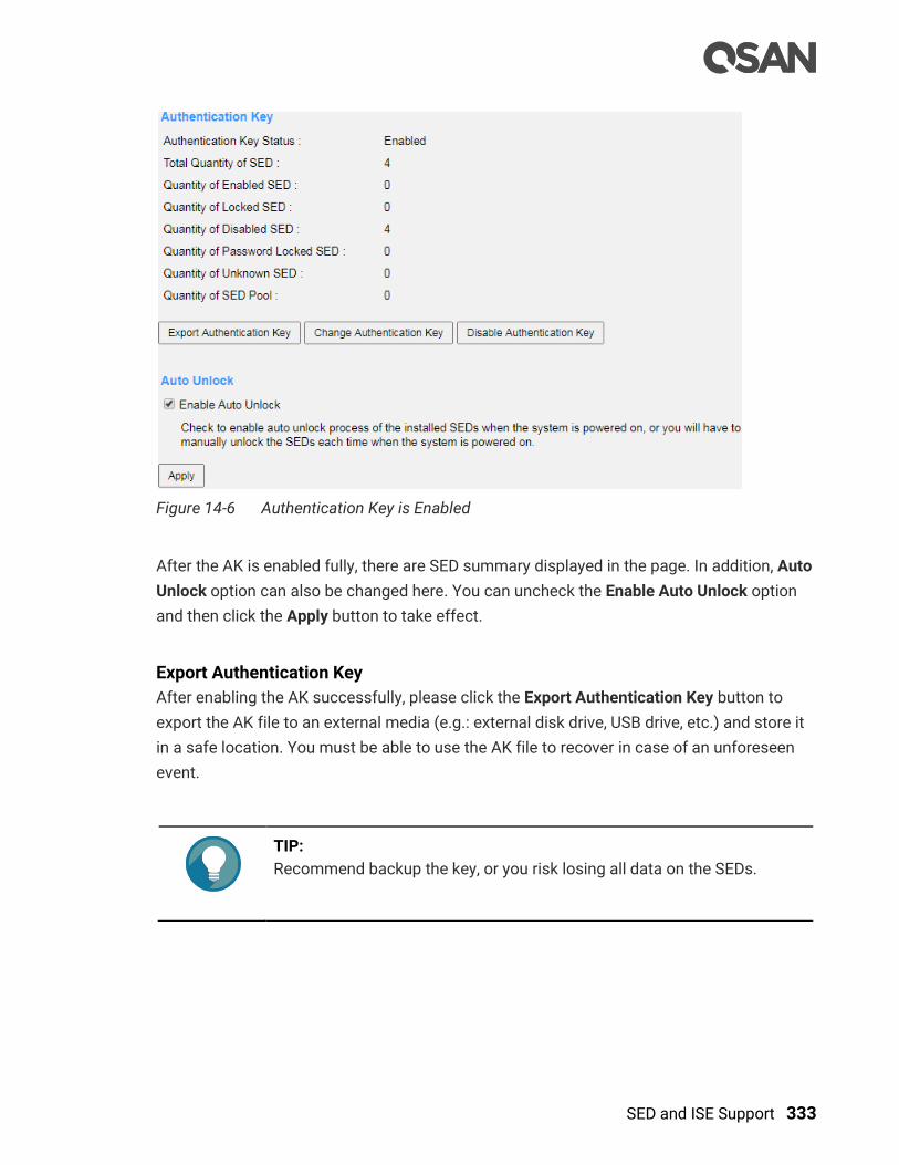
SED and ISE Support 333
Figure 14-6 Authentication Key is Enabled
After the AK is enabled fully, there are SED summary displayed in the page. In addition, Auto
Unlock option can also be changed here. You can uncheck the Enable Auto Unlock option
and then click the Apply button to take effect.
Export Authentication Key
After enabling the AK successfully, please click the Export Authentication Key button to
export the AK file to an external media (e.g.: external disk drive, USB drive, etc.) and store it
in a safe location. You must be able to use the AK file to recover in case of an unforeseen
event.
TIP:
Recommend backup the key, or you risk losing all data on the SEDs.

334 © Copyright 2018 QSAN Technology, Inc. All Right Reserved.
Figure 14-7 Export Authentication Key
1. Enter an Export File name to export the AK file. The default vale is the password hint
plus date and time.
2. Click the OK button to export.
Change Authentication Key
Click the Change Authentication Key button to change the AK. Before changing the AK,
please stop all I/O of the encryption pools within the SEDs. The new AK will be regenerated
based on the new password and set the new authentication key to all enabled SEDs in the
system. If the I/O are still running, it may risk losing data during changing the AK. Here is an
example of changing the AK.
1. Click the Change Authentication Key button to change.

SED and ISE Support 335
Figure 14-8 Change Authentication Key
2. Change the Password for generating the AK. The length of the password is between 4 to
12 characters. Valid characters are [ A~Z | a~z | 0~9 | ~!@#$%^&*_-+=`|\(){}[]:;"'<>,.?/ ].
And enter it again at Confirm Password.
3. Change the Password Hint if necessary. The maximum length of the password hint is 32
characters. Valid characters are [ A~Z | a~z | 0~9 | _- ].
4. Click the OK button to change. If there are enabled SEDs in the system, the system will
change them one by one and display the results.
Disable Authentication Key
If you no longer use disk encryption and there are no encryption pools within the SEDs. The
AK can be disabled. Click the Disable Authentication Key button to disable it.

336 © Copyright 2018 QSAN Technology, Inc. All Right Reserved.
Figure 14-9 Disable Authentication Key
Click the OK button to confirm.
TIP:
The Disable Authentication Key function can be operated when there is
no encryption pools within the SEDs and the SED status of all SEDs is
disabled or unknown.
14.4. Configure SEDs
The SEDs function tab in the Disk Encryption function submenu is only visible when the AK
is enabled. Select the SEDs function tab to display the status of SEDs, initiate SEDs, unlock
SEDs, or erase SEDs.
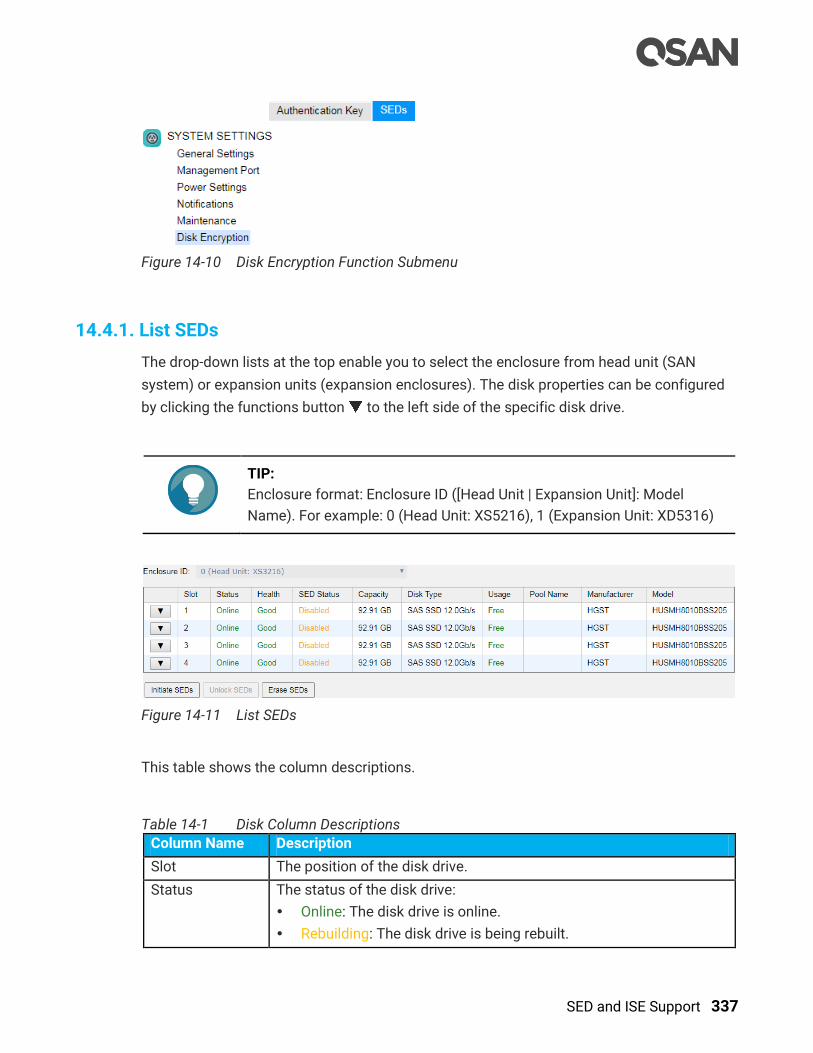
SED and ISE Support 337
Figure 14-10 Disk Encryption Function Submenu
14.4.1. List SEDs
The drop-down lists at the top enable you to select the enclosure from head unit (SAN
system) or expansion units (expansion enclosures). The disk properties can be configured
by clicking the functions button to the left side of the specific disk drive.
TIP:
Enclosure format: Enclosure ID ([Head Unit | Expansion Unit]: Model
Name). For example: 0 (Head Unit: XS5216), 1 (Expansion Unit: XD5316)
Figure 14-11 List SEDs
This table shows the column descriptions.
Table 14-1 Disk Column Descriptions
Column Name Description
Slot The position of the disk drive.
Status The status of the disk drive:
Online: The disk drive is online.
Rebuilding: The disk drive is being rebuilt.
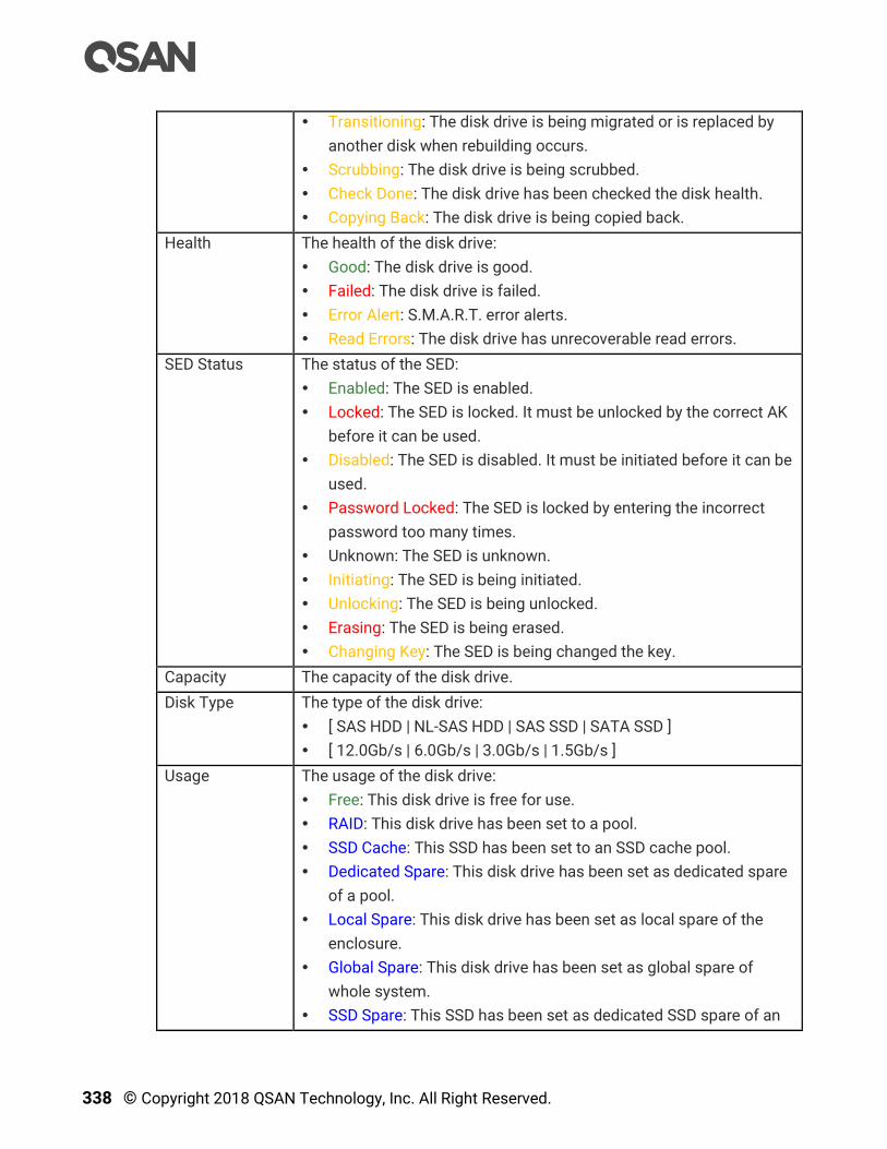
338 © Copyright 2018 QSAN Technology, Inc. All Right Reserved.
Transitioning: The disk drive is being migrated or is replaced by
another disk when rebuilding occurs.
Scrubbing: The disk drive is being scrubbed.
Check Done: The disk drive has been checked the disk health.
Copying Back: The disk drive is being copied back.
Health The health of the disk drive:
Good: The disk drive is good.
Failed: The disk drive is failed.
Error Alert: S.M.A.R.T. error alerts.
Read Errors: The disk drive has unrecoverable read errors.
SED Status The status of the SED:
Enabled: The SED is enabled.
Locked: The SED is locked. It must be unlocked by the correct AK
before it can be used.
Disabled: The SED is disabled. It must be initiated before it can be
used.
Password Locked: The SED is locked by entering the incorrect
password too many times.
Unknown: The SED is unknown.
Initiating: The SED is being initiated.
Unlocking: The SED is being unlocked.
Erasing: The SED is being erased.
Changing Key: The SED is being changed the key.
Capacity The capacity of the disk drive.
Disk Type The type of the disk drive:
[ SAS HDD | NL-SAS HDD | SAS SSD | SATA SSD ]
[ 12.0Gb/s | 6.0Gb/s | 3.0Gb/s | 1.5Gb/s ]
Usage The usage of the disk drive:
Free: This disk drive is free for use.
RAID: This disk drive has been set to a pool.
SSD Cache: This SSD has been set to an SSD cache pool.
Dedicated Spare: This disk drive has been set as dedicated spare
of a pool.
Local Spare: This disk drive has been set as local spare of the
enclosure.
Global Spare: This disk drive has been set as global spare of
whole system.
SSD Spare: This SSD has been set as dedicated SSD spare of an
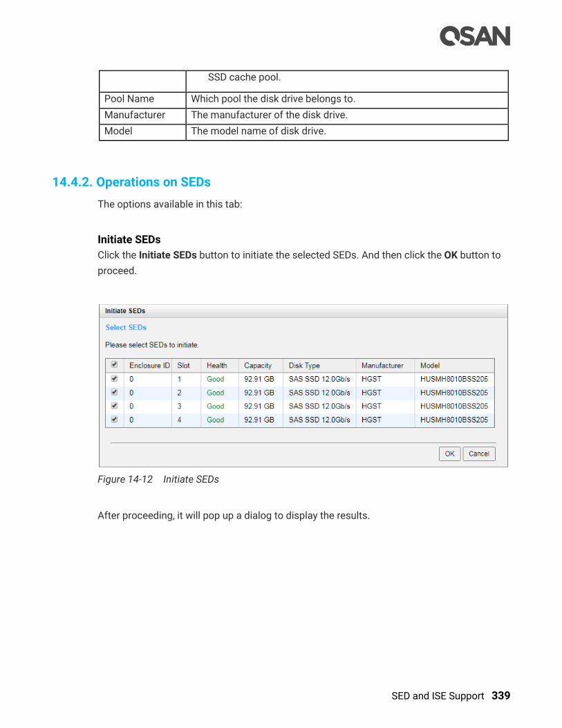
SED and ISE Support 339
SSD cache pool.
Pool Name Which pool the disk drive belongs to.
Manufacturer The manufacturer of the disk drive.
Model The model name of disk drive.
14.4.2. Operations on SEDs
The options available in this tab:
Initiate SEDs
Click the Initiate SEDs button to initiate the selected SEDs. And then click the OK button to
proceed.
Figure 14-12 Initiate SEDs
After proceeding, it will pop up a dialog to display the results.
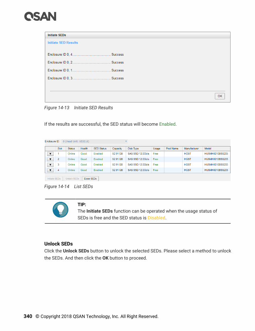
340 © Copyright 2018 QSAN Technology, Inc. All Right Reserved.
Figure 14-13 Initiate SED Results
If the results are successful, the SED status will become Enabled.
Figure 14-14 List SEDs
TIP:
The Initiate SEDs function can be operated when the usage status of
SEDs is free and the SED status is Disabled.
Unlock SEDs
Click the Unlock SEDs button to unlock the selected SEDs. Please select a method to unlock
the SEDs. And then click the OK button to proceed.
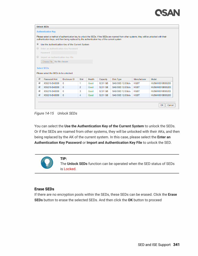
SED and ISE Support 341
Figure 14-15 Unlock SEDs
You can select the Use the Authentication Key of the Current System to unlock the SEDs.
Or if the SEDs are roamed from other systems, they will be unlocked with their AKs, and then
being replaced by the AK of the current system. In this case, please select the Enter an
Authentication Key Password or Import and Authentication Key File to unlock the SED.
TIP:
The Unlock SEDs function can be operated when the SED status of SEDs
is Locked.
Erase SEDs
If there are no encryption pools within the SEDs, these SEDs can be erased. Click the Erase
SEDs button to erase the selected SEDs. And then click the OK button to proceed

342 © Copyright 2018 QSAN Technology, Inc. All Right Reserved.
Figure 14-16 Erase SEDs
After proceeding, it will pop up a dialog to display the results. If the results are successful,
the SED status will become Disabled.
TIP:
The Erase SEDs function can be operated when the usage status of SEDs
is free.
CAUTION:
Erasing the SEDs will change the DEK and delete all data on the SED. The
data on SED can never be restored, please exercise caution.
Erase SED by PSID
If you don’ know where the SED comes from, or the status of the SED is unknown and you
don’t know its password. The last method is to erase the SED by PSID (Physical Secure ID)
which is on the label of the disk drive. Click ▼ -> Erase SED by PSID to erase the SED by
PSID.
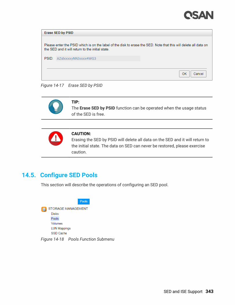
SED and ISE Support 343
Figure 14-17 Erase SED by PSID
TIP:
The Erase SED by PSID function can be operated when the usage status
of the SED is free.
CAUTION:
Erasing the SED by PSID will delete all data on the SED and it will return to
the initial state. The data on SED can never be restored, please exercise
caution.
14.5. Configure SED Pools
This section will describe the operations of configuring an SED pool.
Figure 14-18 Pools Function Submenu
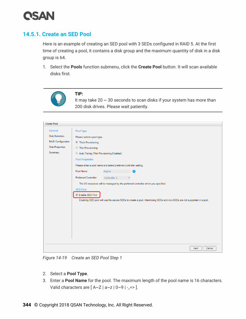
344 © Copyright 2018 QSAN Technology, Inc. All Right Reserved.
14.5.1. Create an SED Pool
Here is an example of creating an SED pool with 3 SEDs configured in RAID 5. At the first
time of creating a pool, it contains a disk group and the maximum quantity of disk in a disk
group is 64.
1. Select the Pools function submenu, click the Create Pool button. It will scan available
disks first.
TIP:
It may take 20 ~ 30 seconds to scan disks if your system has more than
200 disk drives. Please wait patiently.
Figure 14-19 Create an SED Pool Step 1
2. Select a Pool Type.
3. Enter a Pool Name for the pool. The maximum length of the pool name is 16 characters.
Valid characters are [ A~Z | a~z | 0~9 | -_<> ].

SED and ISE Support 345
4. Select a Preferred Controller from the drop-down list. The backend I/O resources in this
pool will be processed by the preferred controller which you specified. This option is
available when dual controllers are installed.
5. Check the Enable SED Pool checkbox. Enabling SED pool will use the secure SEDs to
create a pool. Intermixing SEDs and non-SEDs are not supported in a pool.
6. Click the Next button to continue.
Figure 14-20 Create an SED Pool Step 2
7. Please select disks for pool. The maximum quantity of disk in a disk group is 64. Select
an Enclosure ID from the drop-down list to select disks from expansion enclosures.
8. Click the Next button to continue.
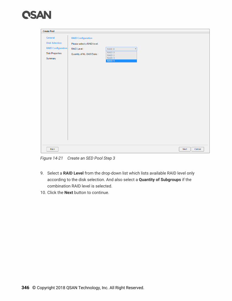
346 © Copyright 2018 QSAN Technology, Inc. All Right Reserved.
Figure 14-21 Create an SED Pool Step 3
9. Select a RAID Level from the drop-down list which lists available RAID level only
according to the disk selection. And also select a Quantity of Subgroups if the
combination RAID level is selected.
10. Click the Next button to continue.

SED and ISE Support 347
Figure 14-22 Create an SED Pool Step 4
11. Disk properties can also be configured optionally in this step:
。 Enable Disk Write Cache: Check to enable the write cache option of disks. Enabling
disk write cache will improve write I/O performance but have a risk of losing data
when power failure.
。 Enable Disk Read-ahead: Check to enable the read-ahead function of disks. System
will preload data to disk buffer based on previously retrieved data. This feature will
efficiently improve the performance of sequential data retrieved.
。 Enable Disk Command Queuing: Check to enable the command queue function of
disks. Send multiple commands to a disk at once to improve performance.
。 Enable Disk Standby: Check to enable the auto spin down function of disks. The
disks will be spun down for power saving when they are idle for the period of time
specified.
12. Click the Next button to continue.

348 © Copyright 2018 QSAN Technology, Inc. All Right Reserved.
Figure 14-23 Create an SED Pool Step 5
13. After confirmation of info on the summary page, click the Finish button to create a pool.
Figure 14-24 An SED Pool is Created
14. An SED pool has been created. If necessary, click the Create Pool button again to create
others.
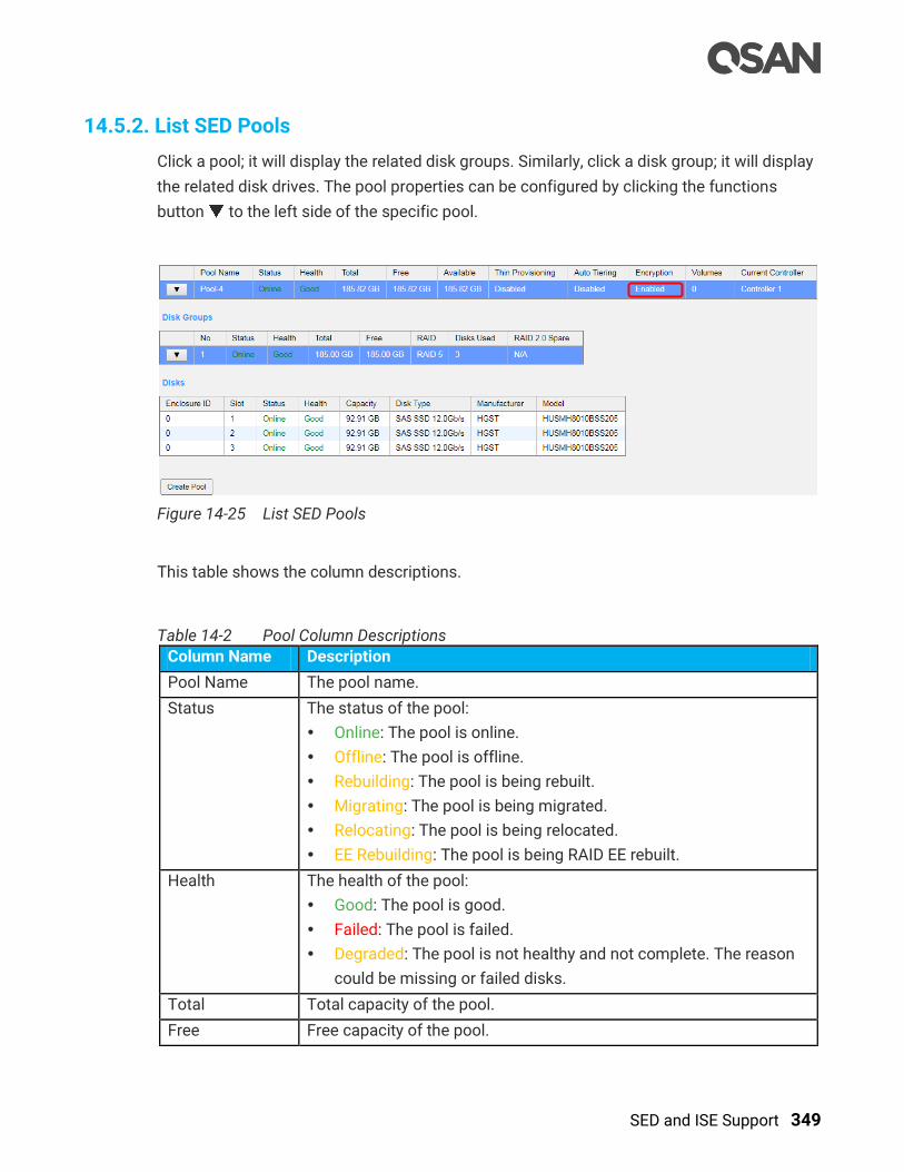
SED and ISE Support 349
14.5.2. List SED Pools
Click a pool; it will display the related disk groups. Similarly, click a disk group; it will display
the related disk drives. The pool properties can be configured by clicking the functions
button to the left side of the specific pool.
Figure 14-25 List SED Pools
This table shows the column descriptions.
Table 14-2 Pool Column Descriptions
Column Name Description
Pool Name The pool name.
Status The status of the pool:
Online: The pool is online.
Offline: The pool is offline.
Rebuilding: The pool is being rebuilt.
Migrating: The pool is being migrated.
Relocating: The pool is being relocated.
EE Rebuilding: The pool is being RAID EE rebuilt.
Health The health of the pool:
Good: The pool is good.
Failed: The pool is failed.
Degraded: The pool is not healthy and not complete. The reason
could be missing or failed disks.
Total Total capacity of the pool.
Free Free capacity of the pool.

350 © Copyright 2018 QSAN Technology, Inc. All Right Reserved.
Available Available capacity of the pool.
Thin
Provisioning
The status of Thin provisioning:
Disabled: The pool is thick provisioned.
Enabled: The pool is thin provisioned.
Auto Tiering The status of Auto Tiering:
Disabled: The pool is auto tiering disabled.
Enabled: The pool is auto tiering enabled.
Not Supported: The pool contains the disk groups with mixed disk
type.
Encryption The Data Secure Mode:
Disabled: The pool is not encrypted.
Enabled: The pool is encrypted.
Volumes The quantity of volumes in the pool.
Current
Controller
(This option is
only visible when
dual controllers
are installed.)
The current running controller of the pool.
Table 14-3 Disk Group Column Descriptions
Column Name Description
No The number of disk group.
Status The status of the disk group:
Online: The disk group is online.
Offline: The disk group is offline.
Rebuilding: The disk group is being rebuilt.
Migrating: The disk group is being migrated.
Relocating: The disk group is being relocated.
EE Rebuilding: The disk group is being RAID EE rebuilt.
Health The health of the disk group:
Good: The disk group is good.
Failed: The disk group fails.
Degraded: The disk group is not healthy and not completed. The
reason could be lack of disk(s) or have failed disk.
Total Total capacity of the disk group.
Free Free capacity of the disk group.

SED and ISE Support 351
RAID The RAID level of the disk group.
Disks Used The quantity of disk drives in the disk group.
RAID 2.0 Spare The quantity of RAID 2.0 spare disk drives in the disk group. Display
N/A is the RAID level is traditional.
Table 14-4 Disk Column Descriptions
Column Name Description
Enclosure ID The enclosure ID.
Slot The position of the disk drive.
Status The status of the disk drive:
Online: The disk drive is online.
Missing: The disk drive is missing in the pool.
Rebuilding: The disk drive is being rebuilt.
Transitioning: The disk drive is being migrated or is replaced by
another disk when rebuilding occurs.
Scrubbing: The disk drive is being scrubbed.
Check Done: The disk drive has been checked the disk health.
Copying Back: The disk drive is being copied back.
Health The health of the disk drive:
Good: The disk drive is good.
Failed: The disk drive is failed.
Error Alert: S.M.A.R.T. error alerts.
Read Errors: The disk drive has unrecoverable read errors.
Capacity The capacity of the disk drive.
Disk Type The type of the disk drive:
[ SAS HDD | NL-SAS HDD | SAS SSD | SATA SSD ]
[ 12.0Gb/s | 6.0Gb/s | 3.0Gb/s | 1.5Gb/s ]
Manufacturer The manufacturer of the disk drive.
Model The model name of disk drive.
14.5.3. Operations on SED Pools
Most operations are described in the Configuring Storage Pools section in the XCubeSAN
SANOS 4.0 User’s Manual. We describe the restrictions about SED pool in the following.
352 © Copyright 2018 QSAN Technology, Inc. All Right Reserved.
Add a Disk Group into the Pool
Click ▼ -> Add Disk Group to add a disk group. Disks can only choose SEDs. Select SEDs
and then click the OK button.
Move Disk Group Member Disks
Click ▼ -> Move Disk Group in disk group to move the member SEDs of the disk group to
other SEDs. They cannot move to non SED. Select SEDs and then click the OK button.
Rebuild on SED Pools
Rebuilding an SED pool will use SED as spare disk, whether it is from global, local, or
dedicated spare.
Create an SSD Cache Pool on SED Pools
Most operations are described in the SSD Cache chapter in the XCubeSAN SANOS 4.0
User’s Manual. We describe the restrictions about creating an SSD cache pool on an SED
pool in the following.
Create an SSD Cache Pool
Select the SSD Cache function submenu; click the Create SSD Cache Pool button. It will
scan available SSDs with SED only.
Data Backup on Encrypted Volumes
Most operations are described in the Data Backup chapter in the XCubeSAN SANOS 4.0
User’s Manual. We describe the tips about data backup on encrypted volumes in he
following.
Local Clone on Encrypted Volume
If executing local clone from an encrypted volume to a non-encrypted volume, it will pop up
a warning message.
Remote Replication on Encrypted Volume
If executing remote replication from an encrypted volume, It will pop up a warning message.
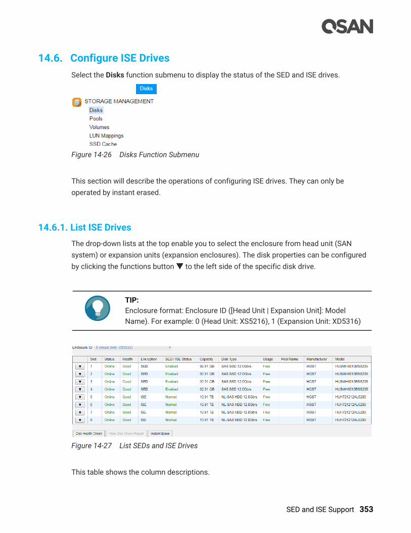
SED and ISE Support 353
14.6. Configure ISE Drives
Select the Disks function submenu to display the status of the SED and ISE drives.
Figure 14-26 Disks Function Submenu
This section will describe the operations of configuring ISE drives. They can only be
operated by instant erased.
14.6.1. List ISE Drives
The drop-down lists at the top enable you to select the enclosure from head unit (SAN
system) or expansion units (expansion enclosures). The disk properties can be configured
by clicking the functions button to the left side of the specific disk drive.
TIP:
Enclosure format: Enclosure ID ([Head Unit | Expansion Unit]: Model
Name). For example: 0 (Head Unit: XS5216), 1 (Expansion Unit: XD5316)
Figure 14-27 List SEDs and ISE Drives
This table shows the column descriptions.
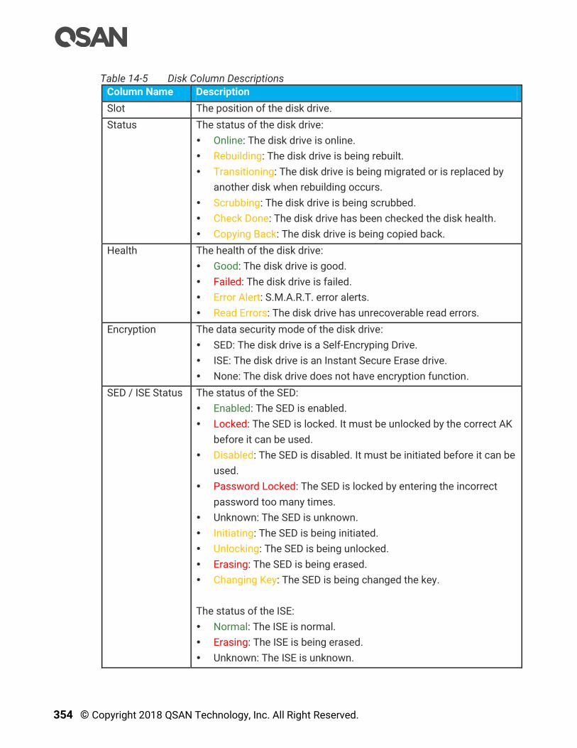
354 © Copyright 2018 QSAN Technology, Inc. All Right Reserved.
Table 14-5 Disk Column Descriptions
Column Name Description
Slot The position of the disk drive.
Status The status of the disk drive:
Online: The disk drive is online.
Rebuilding: The disk drive is being rebuilt.
Transitioning: The disk drive is being migrated or is replaced by
another disk when rebuilding occurs.
Scrubbing: The disk drive is being scrubbed.
Check Done: The disk drive has been checked the disk health.
Copying Back: The disk drive is being copied back.
Health The health of the disk drive:
Good: The disk drive is good.
Failed: The disk drive is failed.
Error Alert: S.M.A.R.T. error alerts.
Read Errors: The disk drive has unrecoverable read errors.
Encryption The data security mode of the disk drive:
SED: The disk drive is a Self-Encryping Drive.
ISE: The disk drive is an Instant Secure Erase drive.
None: The disk drive does not have encryption function.
SED / ISE Status The status of the SED:
Enabled: The SED is enabled.
Locked: The SED is locked. It must be unlocked by the correct AK
before it can be used.
Disabled: The SED is disabled. It must be initiated before it can be
used.
Password Locked: The SED is locked by entering the incorrect
password too many times.
Unknown: The SED is unknown.
Initiating: The SED is being initiated.
Unlocking: The SED is being unlocked.
Erasing: The SED is being erased.
Changing Key: The SED is being changed the key.
The status of the ISE:
Normal: The ISE is normal.
Erasing: The ISE is being erased.
Unknown: The ISE is unknown.
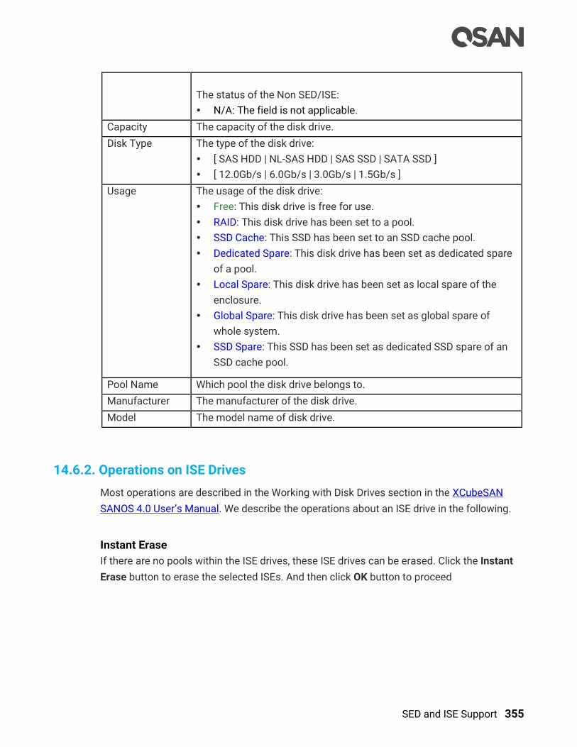
SED and ISE Support 355
The status of the Non SED/ISE:
N/A: The field is not applicable.
Capacity The capacity of the disk drive.
Disk Type The type of the disk drive:
[ SAS HDD | NL-SAS HDD | SAS SSD | SATA SSD ]
[ 12.0Gb/s | 6.0Gb/s | 3.0Gb/s | 1.5Gb/s ]
Usage The usage of the disk drive:
Free: This disk drive is free for use.
RAID: This disk drive has been set to a pool.
SSD Cache: This SSD has been set to an SSD cache pool.
Dedicated Spare: This disk drive has been set as dedicated spare
of a pool.
Local Spare: This disk drive has been set as local spare of the
enclosure.
Global Spare: This disk drive has been set as global spare of
whole system.
SSD Spare: This SSD has been set as dedicated SSD spare of an
SSD cache pool.
Pool Name Which pool the disk drive belongs to.
Manufacturer The manufacturer of the disk drive.
Model The model name of disk drive.
14.6.2. Operations on ISE Drives
Most operations are described in the Working with Disk Drives section in the XCubeSAN
SANOS 4.0 User’s Manual. We describe the operations about an ISE drive in the following.
Instant Erase
If there are no pools within the ISE drives, these ISE drives can be erased. Click the Instant
Erase button to erase the selected ISEs. And then click OK button to proceed

356 © Copyright 2018 QSAN Technology, Inc. All Right Reserved.
Figure 14-28 Instant Erase ISE drives
After proceeding, it will pop up a dialog to display the results.
Figure 14-29 Instant Erase Results
TIP:
The Instant Erase function can be operated when the usage status of ISE
drives is free.

SED and ISE Support 357
CAUTION:
Erasing the ISE drives will change the DEK and delete all data on the ISE
drive. The data on ISE drive can never be restored, please exercise
caution.

358 © Copyright 2018 QSAN Technology, Inc. All Right Reserved.
15. Troubleshooting
This chapter describes how to perform troubleshooting of software. Hardware
troubleshooting is described in the chapter 6, Quick Maintenance in the XCubeSAN
Hardware Owner’s Manual.
15.1. Fault Isolation Methodology
This section presents the basic methodology used to quickly locate faults within the storage
system.
15.1.1. Basic Steps
The basic fault isolation steps are listed below:
Gather fault information, including using system LEDs. Please refer to the chapter 5,
Description of LEDs and Buttons in the XCubeSAN Hardware Owner’s Manual for detail.
Review event logs. Please refer to the chapter 13.1, Log Center section in the Monitoring
chapter.
Determine where the fault is occurring in the system. If the fault is occurring from
hardware, please refer to the chapter 6, Quick Maintenance in the XCubeSAN Hardware
Owner’s Manual for detail.
If required, isolate the fault to a disk drive, configuration, or system. Please refer to the
chapter 15.1.3, Diagnostic Steps section.
If all troubleshooting steps are inconclusive, please contact support for help.
15.1.2. Stopping I/O
When troubleshooting disk drive and connectivity faults, it’s necessary to stop I/O to the
affected volume data from all hosts and remote systems as a data protection precaution.
As an additional data protection precaution, it is helpful to conduct regularly scheduled
backups of your data.

1. SED and ISE Support
With data security issues at the time, the company places a high priority on ensuring that
sensitive data is protected from unauthorized access. Whether it is due to internal policies
or external compliance, access to data remains a matter of high importance for all
organizations. These organizations will seek out storage manufacturers that provide a
stored data protection method, SED (Self-Encrypting Drive), that has both authentication and
encryption features.
In addition, ISE (Instant Secure Erase) drive is designed to protect data on hard disk drives
by instantly resetting the drive back to factory settings and changing the encryption key so
that any data remaining on the drive is cryptographically erased. This means all data on the
drive is permanently and instantly unreadable, as needed.
INFORMATION:
SED (Self-Encryption Drive) and ISE (Instant Secure Erase) drive support is
available in SANOS firmware 1.3.0.
1.1. Overview
15.1.3. Diagnostic Steps
The diagnostic steps are listed below:
If disk drive errors in the event logs are occurring, we suggest replacing a healthy one.
For more information, please refer to the chapter 15.2, Rebuild section.
If the fault is occurring from volume configuration. For example, the pool or volume
configuration is deleted by accident. Please refer to the chapter 15.3, Volume
Restoration section for disaster recovery.
If the fault is occurring from other hardware components of the system, the faulty
component will need to be replaced.
15.2. Rebuild
If any single disk drive of the storage pool in protection RAID level (e.g., RAID 1, 3, 5, 6, 0+1,
10, 30, 50, and 60) fails or has been removed, then the status of pool will be changed to
degraded mode. At the same time, the system will search the spare disk to execute volume
rebuild the degraded pool into complete one.
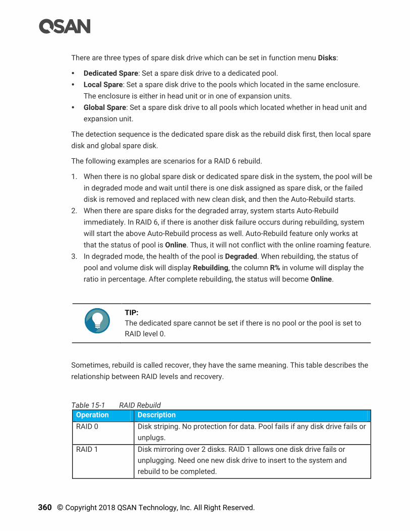
360 © Copyright 2018 QSAN Technology, Inc. All Right Reserved.
There are three types of spare disk drive which can be set in function menu Disks:
Dedicated Spare: Set a spare disk drive to a dedicated pool.
Local Spare: Set a spare disk drive to the pools which located in the same enclosure.
The enclosure is either in head unit or in one of expansion units.
Global Spare: Set a spare disk drive to all pools which located whether in head unit and
expansion unit.
The detection sequence is the dedicated spare disk as the rebuild disk first, then local spare
disk and global spare disk.
The following examples are scenarios for a RAID 6 rebuild.
1. When there is no global spare disk or dedicated spare disk in the system, the pool will be
in degraded mode and wait until there is one disk assigned as spare disk, or the failed
disk is removed and replaced with new clean disk, and then the Auto-Rebuild starts.
2. When there are spare disks for the degraded array, system starts Auto-Rebuild
immediately. In RAID 6, if there is another disk failure occurs during rebuilding, system
will start the above Auto-Rebuild process as well. Auto-Rebuild feature only works at
that the status of pool is Online. Thus, it will not conflict with the online roaming feature.
3. In degraded mode, the health of the pool is Degraded. When rebuilding, the status of
pool and volume disk will display Rebuilding, the column R% in volume will display the
ratio in percentage. After complete rebuilding, the status will become Online.
TIP:
The dedicated spare cannot be set if there is no pool or the pool is set to
RAID level 0.
Sometimes, rebuild is called recover, they have the same meaning. This table describes the
relationship between RAID levels and recovery.
Table 15-1 RAID Rebuild
Operation Description
RAID 0 Disk striping. No protection for data. Pool fails if any disk drive fails or
unplugs.
RAID 1 Disk mirroring over 2 disks. RAID 1 allows one disk drive fails or
unplugging. Need one new disk drive to insert to the system and
rebuild to be completed.
1. SED and ISE Support
With data security issues at the time, the company places a high priority on ensuring that
sensitive data is protected from unauthorized access. Whether it is due to internal policies
or external compliance, access to data remains a matter of high importance for all
organizations. These organizations will seek out storage manufacturers that provide a
stored data protection method, SED (Self-Encrypting Drive), that has both authentication and
encryption features.
In addition, ISE (Instant Secure Erase) drive is designed to protect data on hard disk drives
by instantly resetting the drive back to factory settings and changing the encryption key so
that any data remaining on the drive is cryptographically erased. This means all data on the
drive is permanently and instantly unreadable, as needed.
INFORMATION:
SED (Self-Encryption Drive) and ISE (Instant Secure Erase) drive support is
available in SANOS firmware 1.3.0.
1.1. Overview
N-way mirror Extension to RAID 1 level. It has N copies of the disk. N-way mirror
allows N-1 disk drives failure or unplugging.
RAID 3 Striping with parity on the dedicated disk. RAID 3 allows one disk drive
failure or unplugging.
RAID 5 Striping with interspersed parity over the member disks. RAID 5 allows
one disk drive failure or unplugging.
RAID 6 2-dimensional parity protection over the member disks. RAID 6 allows
two disk drives failure or unplugging. If it needs to rebuild two disk
drives at the same time, it will rebuild the first one, then the other in
sequence.
RAID 0+1 Mirroring of RAID 0 volumes. RAID 0+1 allows two disk drive failures
or unplugging, but at the same array.
RAID 10 Striping over the member of RAID 1 volumes. RAID 10 allows two disk
drive failure or unplugging, but in different arrays.
RAID 30 Striping over the member of RAID 3 volumes. RAID 30 allows two disk
drive failure or unplugging, but in different arrays.
RAID 50 Striping over the member of RAID 5 volumes. RAID 50 allows two disk
drive failures or unplugging, but in different arrays.
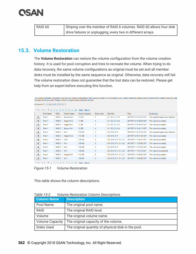
362 © Copyright 2018 QSAN Technology, Inc. All Right Reserved.
RAID 60 Striping over the member of RAID 6 volumes. RAID 60 allows four disk
drive failures or unplugging, every two in different arrays.
15.3. Volume Restoration
The Volume Restoration can restore the volume configuration from the volume creation
history. It is used for pool corruption and tries to recreate the volume. When trying to do
data recovery, the same volume configurations as original must be set and all member
disks must be installed by the same sequence as original. Otherwise, data recovery will fail.
The volume restoration does not guarantee that the lost data can be restored. Please get
help from an expert before executing this function.
Figure 15-1 Volume Restoration
This table shows the column descriptions.
Table 15-2 Volume Restoration Column Descriptions
Column Name Description
Pool Name The original pool name.
RAID The original RAID level.
Volume The original volume name.
Volume Capacity The original capacity of the volume.
Disks Used The original quantity of physical disk in the pool.

1. SED and ISE Support
With data security issues at the time, the company places a high priority on ensuring that
sensitive data is protected from unauthorized access. Whether it is due to internal policies
or external compliance, access to data remains a matter of high importance for all
organizations. These organizations will seek out storage manufacturers that provide a
stored data protection method, SED (Self-Encrypting Drive), that has both authentication and
encryption features.
In addition, ISE (Instant Secure Erase) drive is designed to protect data on hard disk drives
by instantly resetting the drive back to factory settings and changing the encryption key so
that any data remaining on the drive is cryptographically erased. This means all data on the
drive is permanently and instantly unreadable, as needed.
INFORMATION:
SED (Self-Encryption Drive) and ISE (Instant Secure Erase) drive support is
available in SANOS firmware 1.3.0.
1.1. Overview
Disk Slot The original physical disk locations.
Time The last action time of the volume.
Event Logs The last event of the volume.
TIP:
When attempting data recovery, the same volume configurations as the
original must be set and all member disks must be installed by the same
sequence as original. Otherwise, data recovery will fail.
CAUTION:
Performing data recovery does not guarantee that the lost data can be
restored 100%. It depends on the real operation and the degree of
physical damages on disks. Users assume all risk when attempting data
recovery procedures.

364 © Copyright 2018 QSAN Technology, Inc. All Right Reserved.
15.3.1. Configure Volume Restoration
The options available in this tab:
Restore the Volume
Click ▼ -> Restore to restore the deleted volume in the pool. And then click the OK button to
proceed.

Support and Other Resources 365
16. Support and Other Resources
16.1. Getting Technical Support
After installing your device, locate the serial number on the sticker located on the side of the
chassis or from the SANOS UI -> MAINTINANCE > System Information and use it to register
your product at https://partner.qsan.com/ (End-User Registration). We recommend
registering your product in QSAN partner website for firmware updates, document download,
and latest news in eDM. To contact QSAN Support, please use the following information.
Via the Web: https://qsan.com/support
Via Telephone: +886-2-7720-2118 extension 136
(Service hours: 09:30 - 18:00, Monday - Friday, UTC+8)
Via Skype Chat, Skype ID: qsan.support
(Service hours: 09:30 - 02:00, Monday - Friday, UTC+8, Summer time: 09:30 - 01:00)
Via Email: [email protected]
Information to Collect
Product name, model or version, and serial number
Operating system name and version
Firmware version
Error messages or capture screenshots
Product-specific reports and logs
Add-on products or components installed
Third-party products or components installed
Information for Technical Support
The following system information is necessary for technical support. Please refer to
following for what and where to get the information of your XCubeSAN Series model.
If the technical support requests you to download the Service Package, please navigate in
the SANOS UI -> SYSTEM SETTING -> Maintenance -> System Information, and then click
the Download Service Package button to download. Then the system will automatically
generate a zip file the default download location of your web browser.
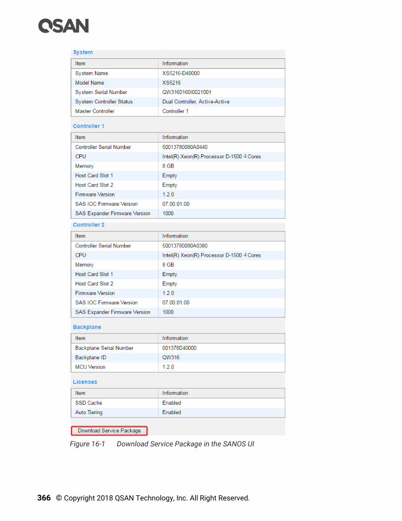
366 © Copyright 2018 QSAN Technology, Inc. All Right Reserved.
Figure 16-1 Download Service Package in the SANOS UI

Support and Other Resources 367
16.2. Online Customer Support
For better customer support, every XCubeSAN series models include the console cable (two
for dual controller models), one for single controller models) for online support. Please
follow the procedures below to setup the online help environment for QSAN support team.
The following procedure will help you to setup the serial console via the console cable that
is enclosed in the shipping carton. The following image is the appearance of the console
cable.
Figure 16-2 Appearance of a Console Cable
Procedures to Setup the Serial Console
1. Setup the serial cable between the controller and one server/host like in the below
image.
Figure 16-3 Connect the Console Cable

368 © Copyright 2018 QSAN Technology, Inc. All Right Reserved.
2. You must use terminal software such as HyperTerminal or Putty to open the console
after the connection is made.
INFORMATION:
For more information about terminal software, please refer to
HyperTerminal: http://www.hilgraeve.com/hyperterminal/
PuTTY: http://www.putty.org/
3. Here we first demonstrate HyperTerminal. The console settings are on the following.
Baud rate: 115200, 8 data bit, no parity, 1 stop bit, and no flow control
Terminal type: vt100
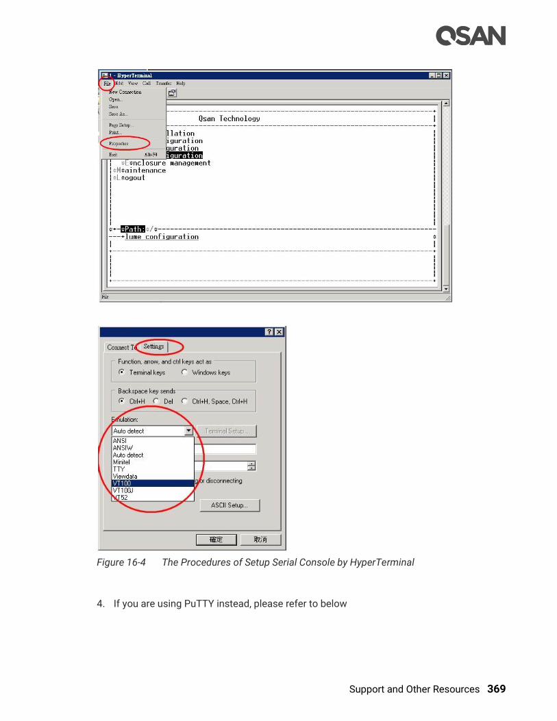
Support and Other Resources 369
Figure 16-4 The Procedures of Setup Serial Console by HyperTerminal
4. If you are using PuTTY instead, please refer to below
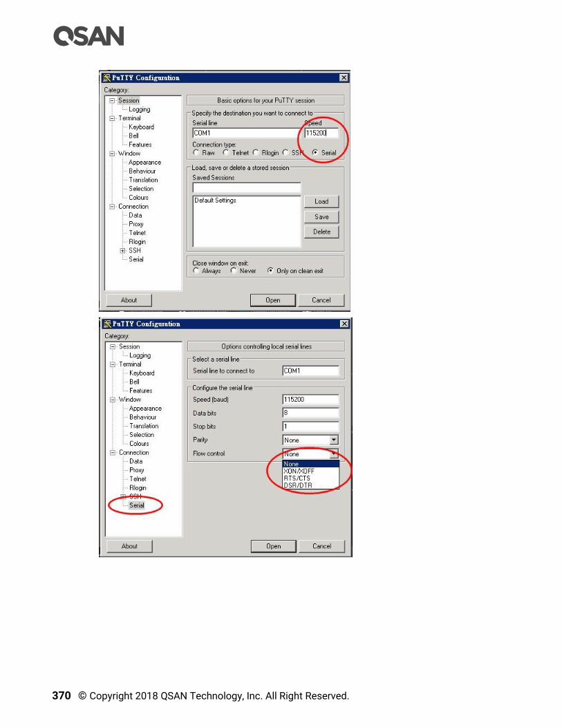
370 © Copyright 2018 QSAN Technology, Inc. All Right Reserved.

Support and Other Resources 371
Figure 16-5 The Procedures of Setup Serial Console by PuTTY
5. Users should be able to login the controller system via console cable by following the
procedures above.
Setup the Connection for Online Support
Following is the procedure to setup the connection for online support via TeamViewer:
1. Please download the TeamViewer from following hyper link:
https://www.teamviewer.com/en/download/
2. Install TeamViewer.
3. Please provide the ID/password showed on the application to QSAN support team
member to join the online support session.
16.3. Accessing Product Updates
To download product updates, please visit QSAN website:
https://qsan.com/download
372 © Copyright 2018 QSAN Technology, Inc. All Right Reserved.
16.4. Documentation Feedback
QSAN is committed to providing documentation that meets and exceeds your expectations.
To help us improve the documentation, email any errors, suggestions, or comments to
When submitting your feedback, include the document title, part number, revision, and
publication date located on the front cover of the document.

Appendix 373
Appendix
Glossary and Acronym List
Common Terminology
Item Description
RAID Redundant Array of Independent Disks. There are different RAID
levels with different degree of data protection, data availability, and
performance to host environment.
Disk The Physical Disk belongs to the member disk of one specific RAID
group.
Pool A collection of removable media. One pool consists of a set of
volumes and owns one RAID level attribute.
Volume Each pool could be divided into several volumes. The volumes from
one pool have the same RAID level, but may have different volume
capacity.
LUN Logical Unit Number. A logical unit number (LUN) is a unique
identifier which enables it to differentiate among separate devices
(each one is a logical unit).
WebUI Web User Interface.
WT Write-Through cache-write policy. A cache technique in which the
completion of a write request is not signaled until data is safely
stored in non-volatile media. Each data is synchronized in both data
cache and accessed physical disks.
WB Write-Back cache-write policy. A cache technique in which the
completion of a write request is signaled as soon as the data is in
cache and actual writing to non-volatile media occurs at a later time.
It speeds up system write performance but needs to bear the risk
where data may be inconsistent between data cache and the physical
disks in one short time interval.
RO Set the volume to be Read-Only.
DS Dedicated Spare disks. The spare disks are only used by one specific

374 © Copyright 2018 QSAN Technology, Inc. All Right Reserved.
RAID group. Others could not use these dedicated spare disks for any
rebuilding purpose.
LS Local Spare disks. The spare disks are only used by the RAID groups
of the local enclosure. Other enclosure could not use these local
spare disks for any rebuilding purpose.
GS Global Spare disks. It is shared for rebuilding purpose. If some RAID
groups need to use the global spare disks for rebuilding, they could
get the spare disks out from the common spare disks pool for such
requirement.
DG DeGraded mode. Not all of the array’s member disks are functioning,
but the array is able to respond to application read and write requests
to its virtual disks.
SCSI Small Computer System Interface
SAS Serial Attached SCSI
S.M.A.R.T. Self-Monitoring Analysis and Reporting Technology
WWN World Wide Name
HBA Host Bus Adapter
SES SCSI Enclosure Services
NIC Network Interface Card
BBM Battery Backup Module
SCM Super Capacitor Module
FC / iSCSI / SAS Terminology
Item Description
FC Fibre Channel
FC-P2P Point-to-Point
FC-AL Arbitrated Loop
FC-SW Switched Fabric
iSCSI Internet Small Computer Systems Interface
LACP Link Aggregation Control Protocol
MPIO Multipath Input/Output
MC/S Multiple Connections per Session
MTU Maximum Transmission Unit
CHAP Challenge Handshake Authentication Protocol. An optional security

Appendix 375
mechanism to control access to an iSCSI storage system over the
iSCSI data ports.
iSNS Internet Storage Name Service
SAS Serial Attached SCSI
Dual Controller Terminology
Item Description
SBB Storage Bridge Bay. The objective of the Storage Bridge Bay Working
Group (SBB) is to create a specification that defines mechanical,
electrical and low-level enclosure management requirements for an
enclosure controller slot that will support a variety of storage
controllers from a variety of independent hardware vendors (“IHVs”)
and system vendors.
6G MUX Bridge board is for SATA II disk to support dual controller mode.
376 © Copyright 2018 QSAN Technology, Inc. All Right Reserved.
End-User License Agreement (EULA)
Please read this document carefully before you use our product or open the package
containing our product.
YOU AGREE TO ACCEPT TERMS OF THIS EULA BY USING OUR PRODUCT, OPENING THE
PACKAGE CONTAINING OUR PRODUCT OR INSTALLING THE SOFTWARE INTO OUR
PRODUCT. IF YOU DO NOT AGREE TO TERMS OF THIS EULA, YOU MAY RETURN THE
PRODUCT TO THE RESELLER WHERE YOU PURCHASED IT FOR A REFUND IN
ACCORDANCE WITH THE RESELLER'S APPLICABLE RETURN POLICY.
General
QSAN Technology, Inc. ("QSAN") is willing to grant you (“User”) a license of software,
firmware and/or other product sold, manufactured or offered by QSAN (“the Product”)
pursuant to this EULA.
License Grant
QSAN grants to User a personal, non-exclusive, non-transferable, non-distributable, non-
assignable, non-sub-licensable license to install and use the Product pursuant to the terms
of this EULA. Any right beyond this EULA will not be granted.
Intellectual Property Right
Intellectual property rights relative to the Product are the property of QSAN or its licensor(s).
User will not acquire any intellectual property by this EULA.
License Limitations
User may not, and may not authorize or permit any third party to: (a) use the Product for any
purpose other than in connection with the Product or in a manner inconsistent with the
design or documentations of the Product; (b) license, distribute, lease, rent, lend, transfer,
assign or otherwise dispose of the Product or use the Product in any commercial hosted or
service bureau environment; (c) reverse engineer, decompile, disassemble or attempt to
discover the source code for or any trade secrets related to the Product, except and only to
the extent that such activity is expressly permitted by applicable law notwithstanding this
limitation; (d) adapt, modify, alter, translate or create any derivative works of the Licensed
Software; (e) remove, alter or obscure any copyright notice or other proprietary rights notice
on the Product; or (f) circumvent or attempt to circumvent any methods employed by QSAN
to control access to the components, features or functions of the Product.

Appendix 377
Disclaimer
QSAN DISCLAIMS ALL WARRANTIES OF PRODUCT, INCLUDING BUT NOT LIMITED TO ANY
MERCHANTABILITY, FITNESS FOR A PARTICULAR PURPOSE, WORKMANLIKE EFFORT,
TITLE, AND NON-INFRINGEMENT. ALL PRODUCTS ARE PROVIDE “AS IS” WITHOUT
WARRANTY OF ANY KIND. QSAN MAKES NO WARRANTY THAT THE PRODUCT WILL BE
FREE OF BUGS, ERRORS, VIRUSES OR OTHER DEFECTS.
IN NO EVENT WILL QSAN BE LIABLE FOR THE COST OF COVER OR FOR ANY DIRECT,
INDIRECT, SPECIAL, PUNITIVE, INCIDENTAL, CONSEQUENTIAL OR SIMILAR DAMAGES OR
LIABILITIES WHATSOEVER (INCLUDING, BUT NOT LIMITED TO LOSS OF DATA,
INFORMATION, REVENUE, PROFIT OR BUSINESS) ARISING OUT OF OR RELATING TO THE
USE OR INABILITY TO USE THE PRODUCT OR OTHERWISE UNDER OR IN CONNECTION
WITH THIS EULA OR THE PRODUCT, WHETHER BASED ON CONTRACT, TORT (INCLUDING
NEGLIGENCE), STRICT LIABILITY OR OTHER THEORY EVEN IF QSAN HAS BEEN ADVISED
OF THE POSSIBILITY OF SUCH DAMAGES.
Limitation of Liability
IN ANY CASE, QSAN’S LIABILITY ARISING OUT OF OR IN CONNECTION WITH THIS EULA OR
THE PRODUCT WILL BE LIMITED TO THE TOTAL AMOUNT ACTUALLY AND ORIGINALLY
PAID BY CUSTOMER FOR THE PRODUCT. The foregoing Disclaimer and Limitation of
Liability will apply to the maximum extent permitted by applicable law. Some jurisdictions
do not allow the exclusion or limitation of incidental or consequential damages, so the
exclusions and limitations set forth above may not apply.
Termination
If User breaches any of its obligations under this EULA, QSAN may terminate this EULA and
take remedies available to QSAN immediately.
Miscellaneous
QSAN reserves the right to modify this EULA.
QSAN reserves the right to renew the software or firmware anytime.
QSAN may assign its rights and obligations under this EULA to any third party without
condition.
This EULA will be binding upon and will inure to User’s successors and permitted
assigns.
378 © Copyright 2018 QSAN Technology, Inc. All Right Reserved.
This EULA shall be governed by and constructed according to the laws of R.O.C. Any
disputes arising from or in connection with this EULA, User agree to submit to the
jurisdiction of Taiwan Shilin district court as first instance trial.