XC440C - XC440D - Emerson Climate XC440C - XC440D are designed to manage compressors or fans in a...
28
XC440C - XC440D
Transcript of XC440C - XC440D - Emerson Climate XC440C - XC440D are designed to manage compressors or fans in a...

XC440C - XC440D
1592001600 XC440C-D GB r2.1 26.08.2015 XC440C - XC440D 2/28
INDEX
1. GENERAL WARNING 4
1.1 PLEASE READ BEFORE USING THIS MANUAL 4
1.2 SAFETY PRECAUTIONS 4
2. GENERAL DESCRIPTION 4
3. FIRST INSTALLATION 4 3.1 HOW TO SET THE KIND OF GAS 5 3.2 HOW TO SET THE RANGE OF THE PRESSURE PROBES 5 3.3 HOW TO SET THE KIND OF DISPLAY: RELATIVE OR ABSOLUTE PRESSURE 5
4. USER INTERFACE 6 4.1 DISPLAYING 6 4.2 KEYBOARD 6 4.3 THE ICONS 6
5. HOW TO SEE AND MODIFY THE SET POINT 7 5.1 HOW TO SEE THE SET POINT OF COMPRESSORS OR FANS 7 5.2 HOW TO MODIFY THE SET POINT OF COMPRESSORS OR FANS 7
6. PARAMETERS PROGRAMMING 8 6.1 HOW TO ENTER THE “PR1” PARAMETER LIST 8 6.2 HOW TO ENTER IN PARAMETERS LIST “PR2” 8 6.3 HOW TO CHANGE PARAMETER VALUES 8
7. HOW TO DISABLED AN OUTPUT 9 7.1 HOW TO DISABLED AN OUTPUT DURING A MAINTENANCE SESSION. 9 7.2 OUTPUT DISABLED SIGNALLING. 9 7.3 REGULATION WITH SOME OUTPUTS DISABLED. 9
8. RUNNING HOURS OF LOADS 9 8.1 HOW TO DISPLAY THE RUNNING HOURS OF A LOAD. 9 8.2 HOW TO RESET THE RUNNING HOURS OF A LOAD. 9
9. ALARM MENU 10 9.1 HOW TO SEE THE ALARMS 10
10. USE OF THE PROGRAMMING “HOT KEY “ 10 10.1 HOW TO PROGRAM A HOT KEY FROM THE INSTRUMENT (UPLOAD) 10 10.2 HOW TO PROGRAM AN INSTRUMENT USING A HOT KEY (DOWNLOAD) 10
11. KEYBOARD LOCKING 10 11.1 HOW TO LOCK THE KEYBOARD 10 11.2 TO UNLOCK THE KEYBOARD 10
12. LIST OF PARAMETERS 11 12.1 PLANT DIMENSIONING AND TYPE OF REGULATION. 11
1592001600 XC440C-D GB r2.1 26.08.2015 XC440C - XC440D 3/28
12.2 PROBES CONFIGURATION 12 12.3 OTHERS INPUTS CONFIGURATION 12 12.4 DISPLAY AND MEASUREMENT UNIT 12 12.5 COMPRESSORS REGULATION 12 12.6 FANS REGULATION 13 12.7 ALARMS – COMPRESSOR SECTION 13 12.8 ALARMS – FANS SECTION 13 12.9 ANALOG OUTPUT (OPTIONAL ONLY FOR XC440D) 14 12.10 OTHER 14
13. TYPE OF REGULATION 14 13.1 DEAD BAND – ONLY FOR COMPRESSORS 14 13.2 PROPORTIONAL BAND – FOR COMPRESSORS OR FANS 15
14. MOUNTING & INSTALLATION 16
15. ELECTRICAL CONNECTIONS 17 15.1 PROBES CONNECTION 17
16. RS485 SERIAL LINK 17
17. ALARM LIST 17 17.1 TYPES OF ALARMS AND SIGNALLING MANAGED 18 17.2 ALARM MUTING 19 17.3 ALARM CONDITIONS – SUMMARY TABLE 19
18. TECHNICAL FEATURES 20
19. WIRING CONNECTIONS 20
20. DEFAULT VALUE XR440C 21
21. DEFAULT VALUE XR440D 23

1592001600 XC440C-D GB r2.1 26.08.2015 XC440C - XC440D 4/28
1. General warning
1.1 Please read before using this manual
This manual is part of the product and should be kept near the instrument for easy and quick reference.
The instrument shall not be used for purposes different from those described hereunder. It cannot be used as a safety
device.
Check the application limits before proceeding.
Dixell Srl reserves the right to change the composition of its products, even without notice, ensuring the same and
unchanged functionality.
1.2 Safety Precautions
Check the supply voltage is correct before connecting the instrument.
Do not expose to water or moisture: use the controller only within the operating limits avoiding sudden temperature
changes with high atmospheric humidity to prevent formation of condensation
Warning: disconnect all electrical connections before any kind of maintenance.
The instrument must not be opened.
In case of failure or faulty operation send the instrument back to the distributor or to “Dixell Srl” (see address) with a
detailed description of the fault.
Consider the maximum current which can be applied to each relay (see Technical Data).
Ensure that the wires for probes, loads and the power supply are separated and far enough from each other, without
crossing or intertwining.
Fit the probe where it is not accessible by the end user.
In case of applications in industrial environments, the use of mains filters (our mod. FT1) in parallel with inductive loads
could be useful.
2. General description
The XC440C - XC440D are designed to manage compressors or fans in a condensing systems such as a pack.
The compressors can be simple, multistage or with different capacities.
Control is by means of a neutral zone or proportional band and is based on the pressure or temperature sensed in the LP
suction (compressors) or HP (condenser) circuits. A special algorithm balances the run hours of the compressors to
distribute the work load uniformly. The controllers can convert pressure and display it as temperature.
The front panel offers complete information on the systems status by displaying the suction and condenser pressure
(temperatures), the status of the loads, possible alarms or maintenance conditions.
Each load has its own alarm input that is able to stop it when activated.
By means of the HOT KEY the controller can be easy programmed at power on. The controller can be connected to the
Dixell controlling and monitoring system, thanks to the serial TTL output, using the standard ModBus RTU protocol.
3. First installation
At first installation, it’s necessary the following:
1. Select the kind of gas.
2. Set the range of the pressure probes.
In the following paragraph a short cut for the above operations.
Chapters 6 Parameters programming and 12 List of parameters will explain in detail these operations.
1592001600 XC440C-D GB r2.1 26.08.2015 XC440C - XC440D 5/28
3.1 How to set the kind of gas
The controller has memorised the relation between temperature and pressure for some gases.
The pre-set gases is: r404.
If another gas is used, act as in the following:
1. Enter the Programming mode by pressing the Set and DOWN key for 3s.
2. Select the “Pr2” parameter. Then enter the password 3 –2 1.
3. Select the FtyP, kind of gas, parameter.
4. Press the “SET” key: the value of the parameter will start blinking.
5. Use “UP” or “DOWN” to change the gas amount the following: Select the gas among the following: r22= R22;
r404=R404A; 507=R507; 134=134; r717= ammonia.
6. Press “SET” to store the new value and move to the following parameter.
To exit: Press SET + UP or wait 30s without pressing a key.
NOTE: the set value is stored even when the procedure is exited by waiting the time-out to expire.
3.2 How to set the range of the pressure probes
According to the part number a controller is pre-set to work with the following pressure probes:
XC440C - XC440D – xxxxA, or XC440C - XC440D – xxxxE: PP11: -0.5÷11 bar (-7÷160 PSI) - relative pressure; XC440C -
XC440D – xxxxB: PP30: 0÷30 bar (0÷435PSI) - relative pressure
If the probes you’re using have a different range act as in the following:
To set the pressure range of the Probe use the parameters:
PA04: Adjustment of read out corresponding to 4mA
PA20: Adjustment of read out corresponding to 20mA
Practically these parameters has to be set with the start and end scale of the probe range.
WARNING: set a value correspondent to absolute pressure.
E.I. PP11 relative pressure transducer, range -0.5÷11.0 bar. PA04=0.50; PA20=12.00.
PP30 relative pressure transducer, range: 0÷30bar. PA04=1.00; PA20=31.00.
How to do:
1. Enter the Programming mode by pressing the Set and DOWN key for 3s.
2. Select the “Pr2” parameter. Then enter the password 3 –2 1.
3. Select the PA04, adjustment of read out corresponding to 4mA, parameter.
4. Press the “SET” key: the value of the parameter will start blinking.
5. Set the lower value of the probe range (lower value +1 if the probe detects relative pressure).
6. Push the SET key to confirm the value. The PA20: adjustment of read out corresponding to 20mA parameter will
be displayed.
7. Set the higher value of the range (higher value +1 if the probe detects relative pressure).
8. Push the SET key to confirm the value. Next parameter will be displayed.
Do the same things for the Probe 2, FA04, FA20 parameters.
3.3 How to set the kind of display: relative or absolute pressure
After setting the probe range by means of the PA04, PA20 parameters, it’s possible to select if the absolute or relative
pressure has to be displayed.
The controller is pre-set for RELATIVE PRESSURE displaying.
If the absolute pressure has to be displayed, act as in the following:
9. Enter the Programming mode by pressing the Set and DOWN key for 3s.
10. Select the “Pr2” parameter. Then enter the password 3 –2 - 1.
1. Select by pushing the UP key the rELP parameter.
2. Push the SET to modify the value.
3. Set the AbS value and push the SET key to confirm it.
To exit: Press SET + UP or wait 30s without pressing a key.
1592001600 XC440C-D GB r2.1 26.08.2015 XC440C - XC440D 6/28
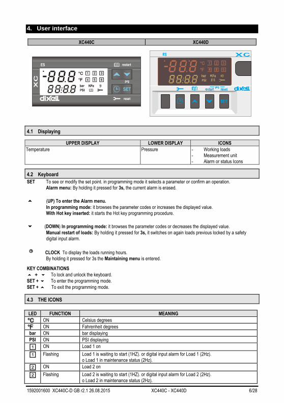
4. User interface
XC440C XC440D
4.1 Displaying
UPPER DISPLAY LOWER DISPLAY ICONS
Temperature Pressure - Working loads
- Measurement unit
- Alarm or status Icons
4.2 Keyboard
SET To see or modify the set point. in programming mode it selects a parameter or confirm an operation.
Alarm menu: By holding it pressed for 3s, the current alarm is erased.
o (UP) To enter the Alarm menu.
In programming mode: it browses the parameter codes or increases the displayed value.
With Hot key inserted: it starts the Hot key programming procedure.
n (DOWN) In programming mode: it browses the parameter codes or decreases the displayed value.
Manual restart of loads: By holding it pressed for 3s, it switches on again loads previous locked by a safety
digital input alarm.
e CLOCK To display the loads running hours.
By holding it pressed for 3s the Maintaining menu is entered.
KEY COMBINATIONS
o + n To lock and unlock the keyboard.
SET + n To enter the programming mode.
SET + o To exit the programming mode.
4.3 THE ICONS
LED FUNCTION MEANING
ON Celsius degrees
ON Fahrenheit degrees
bar ON bar displaying
PSI ON PSI displaying
ON Load 1 on
Flashing Load 1 is waiting to start (1HZ). or digital input alarm for Load 1 (2Hz).
o Load 1 in maintenance status (2Hz).
ON Load 2 on
Flashing Load 2 is waiting to start (1HZ). or digital input alarm for Load 2 (2Hz).
o Load 2 in maintenance status (2Hz).

1592001600 XC440C-D GB r2.1 26.08.2015 XC440C - XC440D 7/28
ON Load 3 on
Flashing Load 3 is waiting to start (1HZ). or digital input alarm for Load 3 (2Hz).
o Load 3 in maintenance status (2Hz).
ON Load 4 on
Flashing Load 4 is waiting to start (1HZ). or digital input alarm for Load 4 (2Hz).
o Load 4 in maintenance status (2Hz).
ON Load 5 on
Flashing Load 5 is waiting to start (1HZ). or digital input alarm for Load 5 (2Hz).
o Load 5 in maintenance status (2Hz).
ON The Maintenance menu has been entered
Flashing One or more loads have been placed in maintenance status
ON Alarm is happening
ON All the stored alarms have been seen
Flashing A new alarm has happened.
5. How to see and modify the set point
5.1 How to see the set point of compressors or fans
If the controller can manage compressors or fans, the set point are displayed in sequence, otherwise only the set point of the
enabled section will be displayed.
1) Push and release the SET key;
2) The Lower display will show the “SEtC” label for compressor/ “SEtF” label for fans, will the Upper
display will show its value.
To exit: push the SET key or wait for 30 without pressing any keys.
5.2 How to modify the set point of compressors or fans
WARNING: before setting the target set points for the first time, check and, if necessary, modify the type of freon
(par. FtyP) and the default unit of measurement (par. dEU) for compressors and fans
PROCEDURE
1. Set the kind of freon by means of the FtyP parameter (see 3.1 How to set the kind of gas)
2. Set the measurement unit (dEU par.).
3. Check and if necessary modify the set point limits (LSE and HSE par.).
1. Push the SET key for more than 2 seconds;
2. The Lower display will show the “SEtC” label for compressor/“SEtF” label for fans, will the Upper
display will show its value flashing.
3. To change the Set value push the o or n within 30s.
4. To memorise the new value and pass to the normal display push the SET key.
To exit: push the SET key or wait for 30 without pressing any keys.

1592001600 XC440C-D GB r2.1 26.08.2015 XC440C - XC440D 8/28
6. Parameters programming
6.1 How to enter the “Pr1” parameter list
To enter the “Pr1” parameter list, user accessible, operate as follows:
1. Hold pressed the SET and DOWN key for 3s.
2. The controller displays the name of the parameter in the Lower display, its value on the Upper display.
3. Press the “SET” key: the value of the parameter will start blinking.
4. Use “UP” or “DOWN” to change the value.
5. Press “SET” to store the new value and move to the following parameter.
To exit: Press SET + UP or wait 30s without pressing a key.
NOTE: the set value is stored even when the procedure is exited by waiting the time-out to expire.
6.2 How to enter in parameters list “Pr2”
The “Pr2” parameter list is protected by a security code (Password).
SECURITY CODE is 321
To access parameters in “Pr2”:
1. Enter the “Pr1” level.
2. Select “Pr2” parameter and press the “SET” key.
3. The flashing value “0 --” is displayed.
4. Use o or n to input the security code and confirm the figure by pressing “SET” key.
5. Repeat operations 2 and 3 for the other digits.
NOTE: each parameter in “Pr2” can be removed or put into “Pr1” (user level) by pressing “SET” + n. When a parameter is
present also in “Pr1” decimal point of the lower display is on.
6.3 How to change parameter values
1. Enter the Programming mode.
2. Select the required parameter with o or n.
3. Press the “SET” key the value start blinking.
4. Use o or n to change its value.
5. Press “SET” to store the new value and move to the following parameter.
To exit: Press SET + UP or wait 15s without pressing a key.
NOTE: the new programming is stored even when the procedure is exited by waiting the time-out.
1592001600 XC440C-D GB r2.1 26.08.2015 XC440C - XC440D 9/28
7. How to disabled an output
To disabled an output during a maintenance session means to exclude the output from the regulation.
7.1 How to disabled an output during a maintenance session.
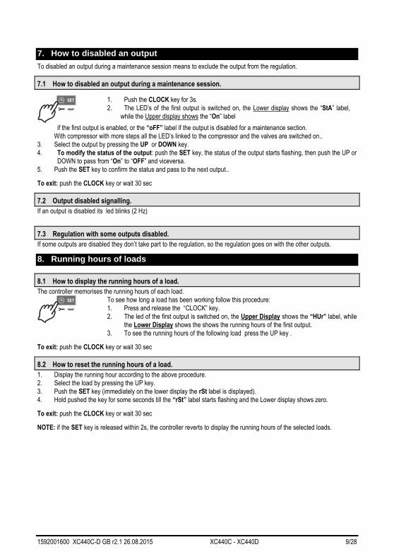
1. Push the CLOCK key for 3s.
2. The LED’s of the first output is switched on, the Lower display shows the “StA” label,
while the Upper display shows the “On” label
if the first output is enabled, or the “oFF” label if the output is disabled for a maintenance section.
With compressor with more steps all the LED’s linked to the compressor and the valves are switched on..
3. Select the output by pressing the UP or DOWN key.
4. To modify the status of the output: push the SET key, the status of the output starts flashing, then push the UP or
DOWN to pass from “On” to “OFF” and viceversa.
5. Push the SET key to confirm the status and pass to the next output..
To exit: push the CLOCK key or wait 30 sec
7.2 Output disabled signalling.
If an output is disabled its led blinks (2 Hz)
7.3 Regulation with some outputs disabled.
If some outputs are disabled they don’t take part to the regulation, so the regulation goes on with the other outputs.
8. Running hours of loads
8.1 How to display the running hours of a load.
The controller memorises the running hours of each load.
To see how long a load has been working follow this procedure:
1. Press and release the “CLOCK” key.
2. The led of the first output is switched on, the Upper Display shows the “HUr” label, while
the Lower Display shows the shows the running hours of the first output.
3. To see the running hours of the following load press the UP key .
To exit: push the CLOCK key or wait 30 sec
8.2 How to reset the running hours of a load.
1. Display the running hour according to the above procedure.
2. Select the load by pressing the UP key.
3. Push the SET key (immediately on the lower display the rSt label is displayed).
4. Hold pushed the key for some seconds till the “rSt” label starts flashing and the Lower display shows zero.
To exit: push the CLOCK key or wait 30 sec
NOTE: if the SET key is released within 2s, the controller reverts to display the running hours of the selected loads.
1592001600 XC440C-D GB r2.1 26.08.2015 XC440C - XC440D 10/28
9. Alarm Menu
The controller memorises the last 20 alarms happened, together with their duration..
To see the alarm codes see par. par. 17 Alarm list
9.1 How to see the alarms
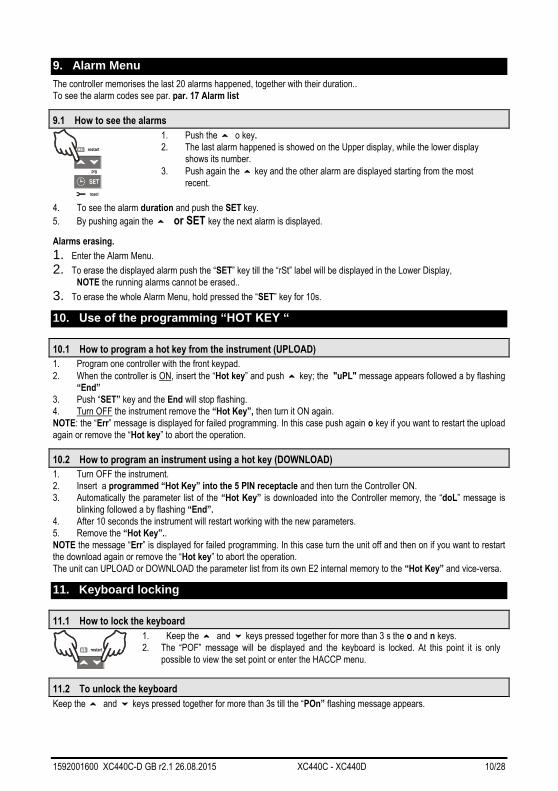
1. Push the o o key.
2. The last alarm happened is showed on the Upper display, while the lower display
shows its number.
3. Push again the o key and the other alarm are displayed starting from the most
recent.
4. To see the alarm duration and push the SET key.
5. By pushing again the o or SET key the next alarm is displayed.
Alarms erasing.
1. Enter the Alarm Menu.
2. To erase the displayed alarm push the “SET” key till the “rSt” label will be displayed in the Lower Display,
NOTE the running alarms cannot be erased..
3. To erase the whole Alarm Menu, hold pressed the “SET” key for 10s.
10. Use of the programming “HOT KEY “
10.1 How to program a hot key from the instrument (UPLOAD)
1. Program one controller with the front keypad.
2. When the controller is ON, insert the “Hot key” and push o key; the "uPL" message appears followed a by flashing
“End”
3. Push “SET” key and the End will stop flashing.
4. Turn OFF the instrument remove the “Hot Key”, then turn it ON again.
NOTE: the “Err” message is displayed for failed programming. In this case push again o key if you want to restart the upload
again or remove the “Hot key” to abort the operation.
10.2 How to program an instrument using a hot key (DOWNLOAD)
1. Turn OFF the instrument.
2. Insert a programmed “Hot Key” into the 5 PIN receptacle and then turn the Controller ON.
3. Automatically the parameter list of the “Hot Key” is downloaded into the Controller memory, the “doL” message is
blinking followed a by flashing “End”.
4. After 10 seconds the instrument will restart working with the new parameters.
5. Remove the “Hot Key”..
NOTE the message “Err” is displayed for failed programming. In this case turn the unit off and then on if you want to restart
the download again or remove the “Hot key” to abort the operation.
The unit can UPLOAD or DOWNLOAD the parameter list from its own E2 internal memory to the “Hot Key” and vice-versa.
11. Keyboard locking
11.1 How to lock the keyboard
1. Keep the o and n keys pressed together for more than 3 s the o and n keys.
2. The “POF” message will be displayed and the keyboard is locked. At this point it is only
possible to view the set point or enter the HACCP menu.
11.2 To unlock the keyboard
Keep the o and n keys pressed together for more than 3s till the “POn” flashing message appears.

1592001600 XC440C-D GB r2.1 26.08.2015 XC440C - XC440D 11/28
12. List of parameters
12.1 Plant dimensioning and type of regulation.
oA1, oA2, oA3, oA4 oA5 only for XC440D Outputs 1- 4(5) configuration: by means of these parameters the plant can be
dimensioned according to the number and type of compressors or fans and the number of steps for each one.
Each relay according to the configuration of the oA(i) parameter can work as:
- Compressor: oAi = cPr,
- Step: oAi = StP
- Fan: oAi = FAn
- Alarm: oAi = ALr
- Not used: oAi = nu
NOTE: also the “Lin” value is present. This value must not be used..
According to the oA1÷oA5 configuration, 2 kinds of plant can be defined:
Rack with compressors only: all the oAi different from FAn Rack with fans only: all the oAi different from CPr of StP
WARNING: It’s not allowed to configure a plant with both compressors and fans.
COMPRESSORS CONFIGURATION
With step compressors the output of compressor has to be set before the output of the step.
ES. Compressor with 3 steps: oA1 = cPr, oA2= StP, oA2 = StP, (oA5 = nu). If an oAi set as step without any previous oAi set as cPr the configuration alarm “CStP” will be activated.
If compressor with different capacities are used (CtyP=dPo), all the oAi must to be configured as cPr (compressor)
otherwise the configuration alarm “CStP” will be activated.
RACK WITH FANS ONLY
If the controller is used for fans, all the oAi must be set as FAn or “nu” not used
CtyP: Compressor type: it selects if the compressors have the same power (homogeneous) or not.
dPo = compressor with different capacities: in this case the regulation is neutral zone.
StP = homogeneous: the regulation can be neutral zone or proportional band.
Scr = don’t set it
StP valve outputs polarity: polarity of the outputs for capacity valves. It determines the state of the relays associated
with the capacity valves (only for homogeneous and stepped-capacity compressors): oP=valve enabled with open
contact; cL= valve enabled with closed contact.
PC1 ..PC4, PC5 only for XC440D Power of compressor 1...5: for setting the power of single compressors. Available only
if CtyP=dPo. The power is identified by a value (range 1÷255) proportional to the capacity of single compressor.
E.I. 3 compressors with following capacity: 10, 20, 40 HP. The parameters have to be set in these way: PC1=10,
PC2=20, PC3=40.
FtyP Freon Type: set the kind of freon used in the plant: r22 = R22; r404= R404A ; 507= R507; 134=134; r717=r717
(ammonia),
rty: Type of regulation (see par. 13 Type of regulation)
db = neutral zone, Pb = proportional band.
CH Type of action: CL = cooling (direct action); Ht = heating (inverse action).
with dead band regulation:
- if pressure/temperature is lower than regulation band, resources are activated.
- if pressure/temperature is bigger than regulation band, resources are deactivated.
with proportional band regulation:
- if pressure/temperature decreases crossing various bands, the resources are activated
- if pressure/temperature increases crossing various bands, the resources are deactivated
Sty Compressor rotation: YES = rotation: this algorithm distributes the working time between the various loads
to ensure even run times. no = fixed sequence: the compressors are enabled and disabled in fixed sequence: first,
second etc.
rot Fans rotation: YES = rotation: this algorithm distributes the working time between the various loads to ensure even
run times. no = fixed sequence: the compressors are enabled and disabled in fixed sequence: first, second etc.

1592001600 XC440C-D GB r2.1 26.08.2015 XC440C - XC440D 12/28
12.2 Probes configuration
12.2.1 Probe configuration
Pbc Probe 1 setting. Cur = 4 ÷ 20 mA probe; ntc = NTC probe, Ptc = NTC probe.
PA04 Adjustment of read out for the Probe 1 (used only if Pbc=Cur). corresponding to 4mA input signal, given by the
suction probe (0 ÷31 bar or 0÷450 PSI or 0÷3100KPA)
Warning: set a value correspondent to absolute pressure. If the transducer measures relative pressure increase
the range of 1 bar.
See also par. 3.2 How to set the range of the pressure probes
E.I. PP11 relative pressure transducer, range -0.5÷12.0 bar. PA04=0.5 (-0.5+1); PA20=12.0 (11+1).
PP30 relative pressure transducer, range: 0÷30bar. PA04=1; PA20=31.
PA20 Adjustment of read out for the Probe 1 corresponding to 20mA input signal, given by the suction probe (0 ÷
31.0 bar or 0÷450 PSI or 0÷3100KPA)) SEE THE WARNING FOR PA04.
CAL Probe 1 calibration (-12.0÷12.0 bar; -12.0÷12.0°C or -20÷20 PSI/°F)
12.3 Others inputs configuration
i1c Configurable digital input polarity (terminals 10-11 for XC440C and terminals 1-2 for XC440D): oP: the digital
input is activated by opening the contact; CL: the digital input is activated by closing the contact.
i1F Configurable digital input polarity functions (terminals 10-11 for XC440C and terminals 1-2 for XC440D): ES =
Energy saving; oFF = instrument shut down; LLi = liquid level alarm
did Configurable digital input delay: (enabled only if i1F=LL) 0÷255min
ALIP Alarm input for compressors and fans polarity: oP: the digital input is activated by opening the contact; CL: the
digital input is activated by closing the contact.
ALMr Manual reset of alarms for compressors and fans.
no= automatic recover of alarm: regulation restart when the correspondent digital input is disabled; yES = manual
recover for the alarms of compressors and fans
See also par. 17.1.2 EA1÷EA5: Compressors or fans safeties alarm.
12.4 Display and Measurement unit
dEU: Default measurement unit for displaying (bar=bar; °C=°C, PSI=PSI; °F=°F)
NOTE1: The dEU parameter sets the measurement unit also for the set point and the following parameters: CAL,
FCAL, Pbd, ESC, LSE, HSE, Pb, ESF, LSF, HSF, LAL, HA, LAF, HAF..
NOTE2: The controller automatically converts values of set point and following parameters CAL, FCAL, Pbd,
ESC, LSE, HSE, Pb, ESF, LSF, HSF, LAL, HA, LAF, HAF in the measurement unit set in dEU parameter. In any
case after modifying this parameter it’s better check and modify if necessary the set point and the above
parameters.
rES Resolution for °C and bar (in = integer; dE = decimal point)
dSP2 Default visualisation of lower display: nu= not used; P1= probe one; P2= probe two; SET1; SET2
dEU2 Lower display probe format: PrS= Pressure; tPr= temperature
rELP Pressure displaying: AbS = absolute pressure; rEL = relative pressure.
NOTE: In this case the pressure displayed, the set point and the following parameters LSE HSE, LSF and HSF
are automatically decreased by 1.0 bar or 14 PSI
12.5 Compressors regulation
Pdb: Proportional band or neutral zone width (0.10÷5.00bar/0.5÷30°C or 1÷80PSI/1÷50°F)
The band (or zone) is symmetrical compared to the target set point, with extremes: set+Pbd/2 ... set-Pbd/2. The
measurement unit depends on the dEU par.
ESC Energy saving value for compressors: (-20÷20bar; -50÷50°C) this value is add to the compressor set point.
Onon Minimum time between 2 following switching ON of the same compressor (0÷255 min).
oFon Minimum time between the switching off of a compressor and the following switching on. (0÷255min).
Note: usually onon is greater than oFon.

1592001600 XC440C-D GB r2.1 26.08.2015 XC440C - XC440D 13/28
Don Time delay between the insertion of two different compressors (0÷99.5min; res. 10s).
doF Time delay between switching off of two different compressors (0÷99.5 min; res. 10s)
donF Minimum time a stage stays switched ON (0÷99.5 min; res. 10s)
Maon Maximum time for compressor ON
FdLy “don” delay enabled also for the first call. If enabled, the triggering of the step is delayed for a “don” value,
respect to the call. (no = “don” not enabled; yES=”don” enabled)
FdLF “doF” delay enabled also for the first switching off. It enables the “doF” delay between the request of a
release and the actual switching off. (no = “doF” not enabled; yES=”doF” enabled)
Odo Regulation delay on start-up: (0÷255s) on switching ON the instrument starts working after the time delay
imposed in this parameter.
LSE Minimum set point: The measurement unit depends on dEU parameter. It sets the minimum value that can be
used for the set point, to prevent the end user from setting incorrect values.
HSE Maximum set point: The measurement unit depends on dEU parameter. It sets the maximum acceptable value
for set point.
12.6 Fans regulation
Pb Proportional band zone width (00.10÷5.00bar/0.5÷30°C or 1÷80PSI/1÷50°F). Set the dEU par. and the target
set point for fans before setting this parameter. The band is symmetrical compared to the target set point, with
extremes: set+Pb/2 ... set-Pb/2. The measurement unit depends on the dEU par.
ESF Energy saving value for fans: (-20÷20bar; -50÷50°C) this value is add to the fans set point.
Fon Time delay between the insertion of two different fans (0÷255sec).
FoF Time delay between switching off of two different compressors (0÷255 sec)
LSF Minimum set point for fans: The measurement unit depends on dEU parameter. It sets the minimum value that
can be used for the set point, to prevent the end user from setting incorrect values.
HSF Maximum set point for fans: The measurement unit depends on dEU parameter. It sets the maximum
acceptable value for set point.
12.7 Alarms – compressor section
PAo Alarm probe exclusion at power on. it is the period starting from instrument switch on, before an alarm probe is
signalled. (0÷255 min). During this time if the pressure is out of range all the compressor are switched on.
LAL Low pressure (temperature) alarm – compressor section: The measurement unit depends on dEU parameter.
It’s always subtracted to the set point. When the value SET-LAL is reached the A03C alarm is enabled, (possibly
after the tAo delay time).
HAL High pressure (temperature) alarm– compressor section: The measurement unit depends on dEU parameter.
It’s always added to the set point. When the value SET+HAL is reached the A04C alarm is enabled, (possibly
after the tAo delay time).
tAo Low and High pressure (temperature) alarms delay– compressor section: (0÷255 min) time interval between
the detection of a pressure (temperature) alarm condition and alarm signalling.
Ser Service request: (1÷9990 hours, res. 10h) number of running hours after that the “A14” maintenance call is
generated.
SPr number of steps engaged with faulty probe. (0÷#compr).
PoPr capacity engaged with faulty probe (0÷100%) It’s used only if CtyP=dPo.
12.8 Alarms – fans section
LAF Low pressure alarm – fans section: The measurement unit depends on the dEU parameter. It’s always referred
to fan set point When the value SETF-LAF is reached the LA2 alarm is enabled, (possibly after the AFd delay
time).
HAF High pressure alarm – fans section: The measurement unit depends on the dEU parameter. It’s always referred
to the set point. When the value SETF+HAF is reached the HA2 alarm is enabled, (possibly after the AFd delay
time).
AFd Low and High pressure alarms delay – fans section: (0÷255 min) time interval between the detection of a
pressure alarm condition in the fans section and alarm signalling.
FPr Number of fans engaged with faulty probe. (0÷#fans).
1592001600 XC440C-D GB r2.1 26.08.2015 XC440C - XC440D 14/28
12.9 Analog output (optional only for XC440D)
LAO Start of scale for analog output: it’s temperature (pressure) detected by the probe which is associated the 4mA
value: (0.0÷51.0bar; -50.0÷150.0°C)
UAO End of scale for analog output: it’s temperature (pressure) detected by the probe which is associated the 20mA
value: (0.0÷51.0bar; -50.0÷150.0°C)
AOM Minimum value for analog output (4 ÷ 20mA)
SAO Percentage of analog output in case of probe failure: (0 ÷ 100%)
12.10 Other
tbA Alarm relay silencing: by pushing one of the keypad buttons. no= alarm relay stays on; yES= alarm relay is
switched off by pushing any keys.
OAP Alarm relay output polarity: cL=closed when activated; oP= opened when activated
oFF Switching ON/OFF enabling from keyboard: (no = disabled; yES = enabled) It permits the switching ON/OFF
of the instrument by pressing the SET key for more than 4s.
Ad1 Compressors address (1 –247) It is used in monitoring system.
Ad2 Fans address (1 –247) It is used in monitoring system.
rEL Software release for internal use.
Ptb Parameter table code: readable only.
Pr2 Access to security code protected menu
13. Type of regulation
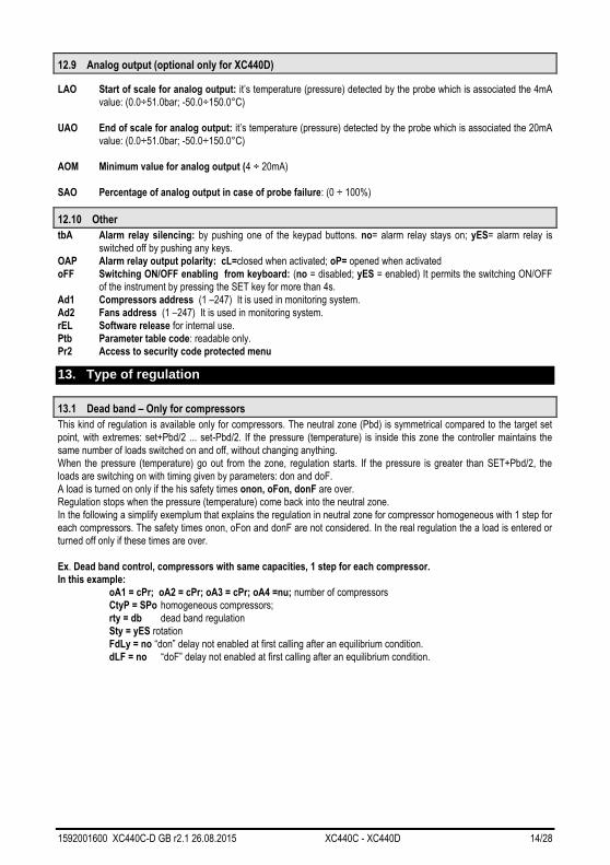
13.1 Dead band – Only for compressors
This kind of regulation is available only for compressors. The neutral zone (Pbd) is symmetrical compared to the target set
point, with extremes: set+Pbd/2 ... set-Pbd/2. If the pressure (temperature) is inside this zone the controller maintains the
same number of loads switched on and off, without changing anything.
When the pressure (temperature) go out from the zone, regulation starts. If the pressure is greater than SET+Pbd/2, the
loads are switching on with timing given by parameters: don and doF.
A load is turned on only if the his safety times onon, oFon, donF are over.
Regulation stops when the pressure (temperature) come back into the neutral zone.
In the following a simplify exemplum that explains the regulation in neutral zone for compressor homogeneous with 1 step for
each compressors. The safety times onon, oFon and donF are not considered. In the real regulation the a load is entered or
turned off only if these times are over.
Ex. Dead band control, compressors with same capacities, 1 step for each compressor.
In this example:
oA1 = cPr; oA2 = cPr; oA3 = cPr; oA4 =nu; number of compressors
CtyP = SPo homogeneous compressors;
rty = db dead band regulation
Sty = yES rotation
FdLy = no “don” delay not enabled at first calling after an equilibrium condition.
dLF = no “doF” delay not enabled at first calling after an equilibrium condition.

1592001600 XC440C-D GB r2.1 26.08.2015 XC440C - XC440D 15/28
Set
C3
CompressorStatus
Time
Pressure
On
C2On
C1 On
Compressor inserction area
neutral zone
don
doF
don
doFdoF
don
Delayfunctioning Time
Time
Set + (Pbd/2)
Set - (Pbd/2)
Compressor disconnection area
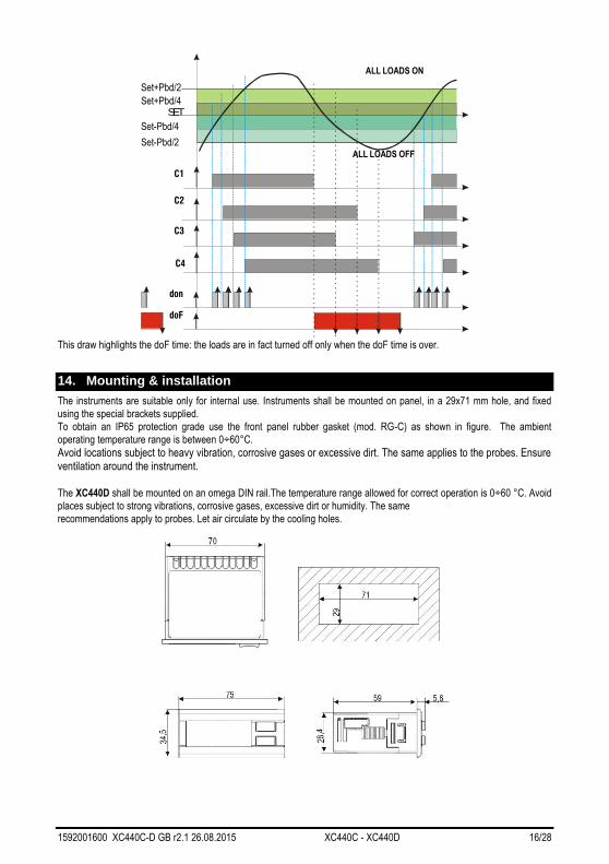
13.2 Proportional Band – for compressors or fans
The regulation band (Pbd) is divided into as many parts as there are stages according to the following formula:
# step = oAi = CPr or StP (number of compressors or steps).
The numbers of stages switched ON is proportional to the value of the input signal: when this distances itself from the target
set point and enters the various bands, the compressors are switched ON, to be then turned OFF when the signal brings
near the set point.
In this way if the pressure is greater than regulation band, all the compressors are on, if the pressure (temperature) is lower
than the regulation band all the compressors are off.
Naturally also for this regulations all the delays (don and doF) safety times (onon, oFon and donF) are valid.
Regulation according to the running hours
The algorithm switch on and off the loads according to the running hours of each load. In this way the running hours are
balanced.
Example
oA1 = cPr; oA2 = cPr; oA3 = cPr; oA4 = cPr: 4 compressors
CtyP = SPo homogeneous compressors.
rty = Pb proportional band regulation
Sty = yES rotation
FdLy = no “don” delay at first call not enabled.
dLF= no “doF” delay at first call not enabled.
1592001600 XC440C-D GB r2.1 26.08.2015 XC440C - XC440D 16/28
C1
C2
C3
C4
SET
Set+Pbd/2
Set-Pbd/2
ZIC
Set+Pbd/4
Set-Pbd/4
don
doF
ALL LOADS ON
ALL LOADS OFF
This draw highlights the doF time: the loads are in fact turned off only when the doF time is over.
14. Mounting & installation
The instruments are suitable only for internal use. Instruments shall be mounted on panel, in a 29x71 mm hole, and fixed
using the special brackets supplied.
To obtain an IP65 protection grade use the front panel rubber gasket (mod. RG-C) as shown in figure. The ambient
operating temperature range is between 0÷60°C.
Avoid locations subject to heavy vibration, corrosive gases or excessive dirt. The same applies to the probes. Ensure ventilation around the instrument. The XC440D shall be mounted on an omega DIN rail.The temperature range allowed for correct operation is 0÷60 °C. Avoid
places subject to strong vibrations, corrosive gases, excessive dirt or humidity. The same
recommendations apply to probes. Let air circulate by the cooling holes.

1592001600 XC440C-D GB r2.1 26.08.2015 XC440C - XC440D 17/28
Figure 1
15. Electrical connections
The controller is provided with screw terminal blocks for wires having section not bigger than 2.5 mm2:
Check power supply data before connection wires.
Keep the probe and the digital input wires separate from the power cable.
Do not exceed the maximum rating current for each relay, check technical data and if the load is bigger, use filtered
contactors.
Before connecting cables make sure the power supply complies with the instrument’s requirements. Separate the input
connection cables from the power supply cables, from the outputs and the power connections. Do not exceed the
maximum current allowed on each relay, in case of heavier loads use a suitable external relay.
15.1 Probes connection
Pressure probe (4 - 20 mA): respect the polarity. If using terminal ends be sure there are no bear parts which could cause
short circuiting or introduce noise disturbance at high frequencies. To minimise the induced disturbances use shielded
cables with the shield connected to earth.
Temperature probe: it is recommended to place the temperature probe away from direct air streams to correctly measure
the temperature.
16. RS485 serial link
All models can be integrated into the monitoring and alarm system XJ500 using the TTL serial port. They use the standard
ModBus RTU protocol, so they can be fitted in a system integrator using this protocol.
The controller has 2 serial addresses first one Ad1 for compressor section, second one Ad2 for fan section.
XJ500: Use Ad1 parameter for Compressor, and Ad2 for fans.
If the Ad2 parameters have the same value of Ad1, the status of the fans is not monitored.
X-WEB300/3000: the values of the 2 addresses Ad1 and Ad2 ca be the same.
17. Alarm list
Usually alarm conditions are signalled by means of:
1. Activation of alarm output relay
2. Buzzer activation
3. Message on proper display
4. Log of alarm: code and duration.
The table at paragraph 17.3

1592001600 XC440C-D GB r2.1 26.08.2015 XC440C - XC440D 18/28
17.1 Types of alarms and signalling managed
17.1.1 A12: Configuration alarm
The following configuration parameters are checked after each modification.:
OA1 OA5 Outputs 1- 5 configuration
CtyP Compressor type
When these parameters are set in wrong way an alarm message is generated:
the label A12 is shown on the upper display, while the lower display signals what wrong setting has created the error:
The following table contains the displayed messages:
Mess. Errata Corrige
nLod Number of loads higher than loads
available in the controller Check number of oAi set as load, this number has to be
lower of equal to the number of relay of the controller.
cStP Load (step) configuration error A relay oA(i) has been set as compressor without a
previous relay oA(i-1) has been set as compressor. EI
oA1 = StP
FAP2 P2 probe not available for fan
regulation Some relays have been set as compressors (oAi = CPr)
some others have been set as fans (oAi = FAn). Set all
the oAi as compressors or fans.
CSP2 P2 probe not available for screw
compressor Check CtyP and set it different from Scr.
17.1.2 EA1÷EA5: Compressors or fans safeties alarm.
Terminals
WARNING: THESE TERMINALS REQUIRE A FREE OF VOLTAGE CONNECTION.
The terminals really used depends on the number of loads. The protections regarding the compressors and fans are
connected to these inputs. If one of these protections is enabling (E.I. for lack of oil or overheating, etc,) the corresponding
load is turn off.
Parameters
ALIP: It establishes if the input is activated by closing (ALIP = cL) or by opening (ALIP = oP) the terminals.
Actions
Every time one input is activated the corresponding output is turned off.
Recovery
Recovery depends on ALMr parameter:
With ALMr = no The instrument restart the standard operating mode when the input is disabled.
With ALMr = yES manual recover for the alarms of compressors and fans. Push the DOWN key for 3s.
17.1.3 P1: probe failure alarm
It is generated by failure in the probe P1.
Parameters
According to the configuration of the controller one of the following parameters is used:
SPr: number of steps engaged with faulty probe. (0÷# oAi = cPr or StP). PoPr: capacity engaged with faulty probe (0÷255) It’s used only if CtyP=dPo.
FPr: Number of fans engaged with faulty probe. (0÷# oAi = FAn)
Recovery
Automatic as soon as probe restarts working.
17.1.4 HA, LA, HA2, LA2High and low pressure (temperature) alarms
This alarm signals that the pressure (temperature) is out of limits established by parameters LAL and HAL for compressors
and LAF –HAF for fans.
The tAo and AFd parameters set the delay between alarm condition and alarm signalling.
Action
The alarm is signalled with standard action. The outputs are unchanged.
1592001600 XC440C-D GB r2.1 26.08.2015 XC440C - XC440D 19/28
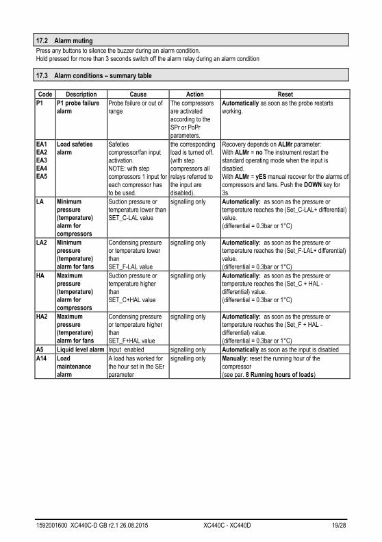
17.2 Alarm muting
Press any buttons to silence the buzzer during an alarm condition.
Hold pressed for more than 3 seconds switch off the alarm relay during an alarm condition
17.3 Alarm conditions – summary table
Code Description Cause Action Reset
P1 P1 probe failure
alarm Probe failure or out of
range
The compressors
are activated
according to the
SPr or PoPr
parameters.
Automatically as soon as the probe restarts
working.
EA1
EA2
EA3
EA4
EA5
Load safeties
alarm Safeties
compressor/fan input
activation.
NOTE: with step
compressors 1 input for
each compressor has
to be used.
the corresponding
load is turned off.
(with step
compressors all
relays referred to
the input are
disabled).
Recovery depends on ALMr parameter:
With ALMr = no The instrument restart the
standard operating mode when the input is
disabled.
With ALMr = yES manual recover for the alarms of
compressors and fans. Push the DOWN key for
3s.
LA Minimum
pressure
(temperature)
alarm for
compressors
Suction pressure or
temperature lower than
SET_C-LAL value
signalling only Automatically: as soon as the pressure or
temperature reaches the (Set_C-LAL+ differential)
value.
(differential = 0.3bar or 1°C)
LA2 Minimum
pressure
(temperature)
alarm for fans
Condensing pressure
or temperature lower
than
SET_F-LAL value
signalling only Automatically: as soon as the pressure or
temperature reaches the (Set_F-LAL+ differential)
value.
(differential = 0.3bar or 1°C)
HA Maximum
pressure
(temperature)
alarm for
compressors
Suction pressure or
temperature higher
than
SET_C+HAL value
signalling only Automatically: as soon as the pressure or
temperature reaches the (Set_C + HAL -
differential) value.
(differential = 0.3bar or 1°C)
HA2 Maximum
pressure
(temperature)
alarm for fans
Condensing pressure
or temperature higher
than
SET_F+HAL value
signalling only Automatically: as soon as the pressure or
temperature reaches the (Set_F + HAL -
differential) value.
(differential = 0.3bar or 1°C)
A5 Liquid level alarm Input enabled signalling only Automatically as soon as the input is disabled
A14 Load
maintenance
alarm
A load has worked for
the hour set in the SEr
parameter
signalling only
Manually: reset the running hour of the
compressor
(see par. 8 Running hours of loads)

1592001600 XC440C-D GB r2.1 26.08.2015 XC440C - XC440D 20/28
18. Technical features
Housing: Self extinguishing ABS.
Case: XC440C Front panel 32x74 mm, depth 60mm;
XC440D DIN modules 70x85 mm; depth 61mm
Mounting : XC440C panel mounting in a 29x71 mm panel cut-out
XC440D DIN RAIL mounted in a omega (3) din rail Frontal protection: IP65 with frontal gasket mod RG-C model.
Connections: screw terminal block,
Power supply: XC440C 12Vac/dc 10%, 24Vac/dc 10%, 50-60Hz.
XC440D 110Vac ± 10%, 230Vac ±10%, 50-60Hz
Power absorption: 5VA max.
Display: 3 digits red led and 4 digit orange led.
Inputs: 1 NTC probe, or 1 PTC probe or 1 4÷20mA transducer.
Digital inputs: XC440C 5 free voltage; XC440D 6 free voltage;
Relay outputs: 5 relay SPST 8(3)A, 250Vac
Serial output : TTL standard
Communication protocol: ModBus – RTU
Data storing: on the non-volatile memory (EEPROM).
Kind of action: 1B; Pollution grade: normal; Software class: A.
Operating temperature: 0÷60 °C.; Storage temperature: -25÷60 °C.
Relative humidity: 2085% (no condensing)
Measuring range: NTC probe: -40÷110°C.
Resolution: 0,1 °C or 1°C; Accuracy (ambient temp. 25°C): ±0,7 °C ±1 digit
19. Wiring connections
1
13
2
14
3 4
16
5
17
9
21
6
18
10
22
8(3)A250V8(3)A8(3) A8(3)A8(3) A
7
19
11
23
8
20
Hot
Key
Supply24V=
LOAD4LOAD3LOAD2LOAD1ALARM
ID1 ID2 ID3 ID4 IDCnf 4÷20mA= 3(gnd); 4(In); 5( )+
12V§
Probe:
PP11 / PP30: Brown (5), White (4)
PTC/NTC: 3-4
4÷20mA= ; 9( )11(In); 12(gnd) +
PTC/NTC= 11(In); 12(gnd)
Load2 Load4Load1 Loa d3
4÷20mAoutput
8(3 )A/ 250VacXC440D
13 14 15 16 17 18 19 20 23 24
1 2 3 9 10 11 124 5 6 7 8
cSupply
HOT
KEY
ID1ID2ID3ID4Conf.
8(3)A8(3)A 8(3)A8(3)A
Load5
Pb1ID5
c
12Vdc
Probe:
PP11 / PP30: Brown (9), White (11)
PTC/NTC: 11-12
1592001600 XC440C-D GB r2.1 26.08.2015 XC440C - XC440D 21/28
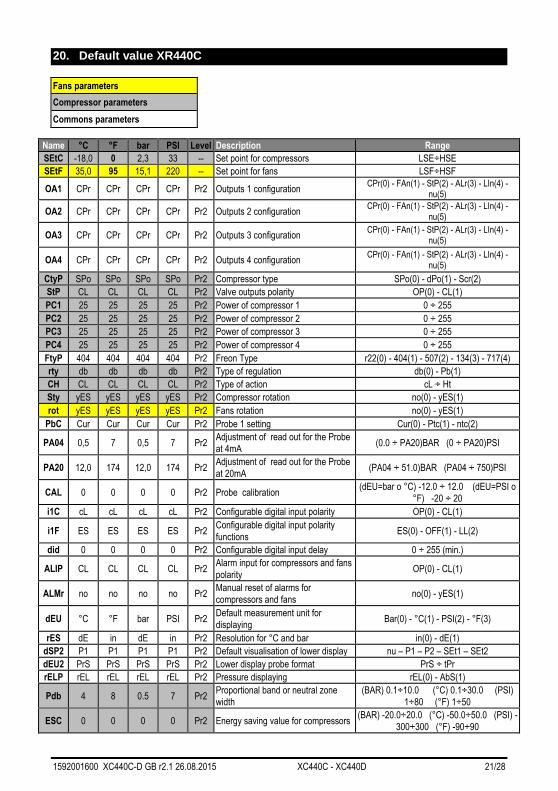
20. Default value XR440C
Name °C °F bar PSI Level Description Range
SEtC -18,0 0 2,3 33 -- Set point for compressors LSE÷HSE
SEtF 35,0 95 15,1 220 -- Set point for fans LSF÷HSF
OA1 CPr CPr CPr CPr Pr2 Outputs 1 configuration CPr(0) - FAn(1) - StP(2) - ALr(3) - LIn(4) -
nu(5)
OA2 CPr CPr CPr CPr Pr2 Outputs 2 configuration CPr(0) - FAn(1) - StP(2) - ALr(3) - LIn(4) -
nu(5)
OA3 CPr CPr CPr CPr Pr2 Outputs 3 configuration CPr(0) - FAn(1) - StP(2) - ALr(3) - LIn(4) -
nu(5)
OA4 CPr CPr CPr CPr Pr2 Outputs 4 configuration CPr(0) - FAn(1) - StP(2) - ALr(3) - LIn(4) -
nu(5)
CtyP SPo SPo SPo SPo Pr2 Compressor type SPo(0) - dPo(1) - Scr(2)
StP CL CL CL CL Pr2 Valve outputs polarity OP(0) - CL(1)
PC1 25 25 25 25 Pr2 Power of compressor 1 0 ÷ 255
PC2 25 25 25 25 Pr2 Power of compressor 2 0 ÷ 255
PC3 25 25 25 25 Pr2 Power of compressor 3 0 ÷ 255
PC4 25 25 25 25 Pr2 Power of compressor 4 0 ÷ 255
FtyP 404 404 404 404 Pr2 Freon Type r22(0) - 404(1) - 507(2) - 134(3) - 717(4)
rty db db db db Pr2 Type of regulation db(0) - Pb(1)
CH CL CL CL CL Pr2 Type of action cL ÷ Ht
Sty yES yES yES yES Pr2 Compressor rotation no(0) - yES(1)
rot yES yES yES yES Pr2 Fans rotation no(0) - yES(1)
PbC Cur Cur Cur Cur Pr2 Probe 1 setting Cur(0) - Ptc(1) - ntc(2)
PA04 0,5 7 0,5 7 Pr2 Adjustment of read out for the Probe
at 4mA (0.0 ÷ PA20)BAR (0 ÷ PA20)PSI
PA20 12,0 174 12,0 174 Pr2 Adjustment of read out for the Probe
at 20mA (PA04 ÷ 51.0)BAR (PA04 ÷ 750)PSI
CAL 0 0 0 0 Pr2 Probe calibration (dEU=bar o °C) -12.0 ÷ 12.0 (dEU=PSI o
°F) -20 ÷ 20
i1C cL cL cL cL Pr2 Configurable digital input polarity OP(0) - CL(1)
i1F ES ES ES ES Pr2 Configurable digital input polarity
functions ES(0) - OFF(1) - LL(2)
did 0 0 0 0 Pr2 Configurable digital input delay 0 ÷ 255 (min.)
ALIP CL CL CL CL Pr2 Alarm input for compressors and fans
polarity OP(0) - CL(1)
ALMr no no no no Pr2 Manual reset of alarms for
compressors and fans no(0) - yES(1)
dEU °C °F bar PSI Pr2 Default measurement unit for
displaying Bar(0) - °C(1) - PSI(2) - °F(3)
rES dE in dE in Pr2 Resolution for °C and bar in(0) - dE(1)
dSP2 P1 P1 P1 P1 Pr2 Default visualisation of lower display nu – P1 – P2 – SEt1 – SEt2
dEU2 PrS PrS PrS PrS Pr2 Lower display probe format PrS ÷ tPr
rELP rEL rEL rEL rEL Pr2 Pressure displaying rEL(0) - AbS(1)
Pdb 4 8 0.5 7 Pr2 Proportional band or neutral zone
width
(BAR) 0.1÷10.0 (°C) 0.1÷30.0 (PSI)
1÷80 (°F) 1÷50
ESC 0 0 0 0 Pr2 Energy saving value for compressors (BAR) -20.0÷20.0 (°C) -50.0÷50.0 (PSI) -
300÷300 (°F) -90÷90
Fans parameters
Compressor parameters
Commons parameters

1592001600 XC440C-D GB r2.1 26.08.2015 XC440C - XC440D 22/28
Name °C °F bar PSI Level Description Range
OnOn 5 5 5 5 Pr2
Minimum time between 2 following
switching ON of the same
compressor
0 ÷ 255 (min.)
OFOn 2 2 2 2 Pr2
Minimum time between the switching
off of a compressor and the following
switching on
0 ÷ 255 (min.)
don 0,3 0,3 0,3 0,3 Pr2 Time delay between the insertion of
two different compressors 0 ÷ 99.5 (min.10sec)
doF 0,1 0,1 0,1 0,1 Pr2 Time delay between switching off of
two different compressors 0 ÷ 99.5 (min.10sec)
donF 0,3 0,3 0,3 0,3 Pr2 Minimum time a stage stays switched
ON 0 ÷ 99.5 (min.10sec)
MAon 0 0 0 0 Pr2 Maximum time for compressor ON 0 ÷ 24 h
FdLy no no no no Pr2 “don” delay enabled also for the first
call no(0) - yES(1)
FdLF no no no no Pr2 doF” delay enabled also for the first
switching off no(0) - yES(1)
odo 20 20 20 20 Pr2 Regulation delay on start-up 0 ÷ 255 (sec.)
LSE -40 -40 0,3 5 Pr2 Minimum set point)
BAR: (PA04÷HSE)abs; ((PA04-
1.013)÷HSE)rel; °C: -50.0÷HSE; PSI:
(PA04÷HSE)abs o ((PA04-14)÷HSE)rel; °F:
-58.0÷HSE
HSE 10 50 7,2 100 Pr2 Maximum set point
BAR :(LSE÷PA20)abs o (LSE÷(PA20-
1.013))rel; °C:LSE ÷ 150.0; PSI:(LSE ÷
PA20)abs o (LSE÷(PA20-14))rel; °F: LSE
÷ 302
Pb 4 8 2.0 24 Pr2 Proportional band zone width (BAR) 0.1÷10.0 (°C) 0.1÷30.0 (PSI)
1÷80 (°F) 1÷50.0
ESF 0 0 0 0 Pr2 Energy saving value for fans (BAR) -20.0÷20.0 (°C) -50.0÷50.0 (PSI) -
300÷300 (°F) -90÷90
Fon 15 15 15 15 Pr2 Time delay between the insertion of
two different fans 0 ÷ 255 (sec)
FoF 5 5 5 5 Pr2 Time delay between switching off of
two different fans 0 ÷ 255 (sec)
LSF 10 50 7,2 100 Pr2 Lower set for fans
BAR:(FA04 ÷ HSF)abs, ((FA04 - 1.013) ÷
HSF)rel; °C:-50.0 ÷ HSF; PSI: (FA04 ÷
HSF)abs o ((FA04-14) ÷ HSF)rel; °F: -58.0
÷ HSF
HSF 60 140 27,8 404 Pr2 Higher set for fans
BAR: (LSF ÷ F20); abs: (LSF ÷ (F20-
1.0))rel; °C:LSF ÷ 150.0; PSI: (LSF ÷
FA20)abs o (LSF÷(FA20 - 14))rel; °F: LSF
÷ 302
PAO 30 30 30 30 Pr2 Alarm probe exclusion at power on 0 ÷ 255 (min.)
LAL 15,0 30 1,5 21 Pr1 Low pressure (temperature) alarm –
compressor section
(0.1 ÷ 30.0)BAR (0.1 ÷ 100.0)°C (1 ÷
430)PSI (1 ÷ 200.0)°F
HAL 20.0 40 2,5 46 Pr1 High pressure (temperature) alarm–
compressor section
(0.1 ÷ 30.0)BAR (0.1 ÷ 100.0)°C (1 ÷
430)PSI (1 ÷ 200.0)°F
tAo 15 15 15 15 Pr1 Low and High pressure (temperature)
alarms delay– compressor section 0 ÷ 255 (min.)
SEr 999 999 999 999 Pr2 Service request 1 ÷ 999 (0= ESCLUSO) (10 ore)
SPr 2 2 2 2 Pr2 number of steps engaged with faulty
probe 0 ÷ (nCPR)
PoPr 50 50 50 50 Pr2 capacity engaged with faulty probe 0 ÷ 100 (%)
LAF 20 40 6,7 96 Pr1 Low pressure alarm – fans section (0.1 ÷ 30.0)BAR (0.1 ÷ 100.0)°C (1 ÷
430)PSI (1 ÷ 200.0)°F
1592001600 XC440C-D GB r2.1 26.08.2015 XC440C - XC440D 23/28
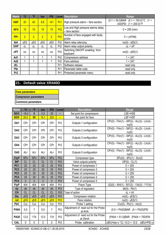
Name °C °F bar PSI Level Description Range
HAF 20 40 9,8 141 Pr1 High pressure alarm – fans section (0.1 ÷ 30.0)BAR (0.1 ÷ 100.0)°C (1 ÷
430)PSI (1 ÷ 200.0)°F
AFd 15 15 15 15 Pr2 Low and High pressure alarms delay
– fans section 0 ÷ 255 (min)
FPr 2 2 2 2 Pr2 Number of fans engaged with faulty
probe 0 ÷ (nFAN)
tbA yES yES yES yES Pr2 Alarm relay silencing no(0) - yES(1)
OAP cL cL cL cL Pr2 Alarm relay output polarity cL ÷ oP
oFF no no no no Pr2 Switching ON/OFF enabling from
keyboard no(0) - yES(1)
Ad1 1 1 1 1 Pr2 Compressors address 1 ÷ 247
Ad2 1 1 1 1 Pr2 Fans address 1 ÷ 247
rEL Pr1 Software release read only
Ptb Pr1 Parameter table code read only
Pr2 Pr1 Protected parameter menu read only
21. Default value XR440D
Name °C °F bar PSI Level Description Range
SEtC -18,0 0 2,3 33 -- Set point for compressors LSE÷HSE
SEtF 35,0 95 15,1 220 -- Set point for fans LSF÷HSF
OA1 CPr CPr CPr CPr Pr2 Outputs 1 configuration CPr(0) - FAn(1) - StP(2) - ALr(3) - LIn(4) -
nu(5)
OA2 CPr CPr CPr CPr Pr2 Outputs 2 configuration CPr(0) - FAn(1) - StP(2) - ALr(3) - LIn(4) -
nu(5)
OA3 CPr CPr CPr CPr Pr2 Outputs 3 configuration CPr(0) - FAn(1) - StP(2) - ALr(3) - LIn(4) -
nu(5)
OA4 CPr CPr CPr CPr Pr2 Outputs 4 configuration CPr(0) - FAn(1) - StP(2) - ALr(3) - LIn(4) -
nu(5)
OA5 ALr ALr ALr ALr Pr2 Outputs 5 configuration CPr(0) - FAn(1) - StP(2) - ALr(3) - LIn(4) -
nu(5)
CtyP SPo SPo SPo SPo Pr2 Compressor type SPo(0) - dPo(1) - Scr(2)
StP CL CL CL CL Pr2 Valve outputs polarity OP(0) - CL(1)
PC1 25 25 25 25 Pr2 Power of compressor 1 0 ÷ 255
PC2 25 25 25 25 Pr2 Power of compressor 2 0 ÷ 255
PC3 25 25 25 25 Pr2 Power of compressor 3 0 ÷ 255
PC4 25 25 25 25 Pr2 Power of compressor 4 0 ÷ 255
PC5 0 0 0 0 Pr2 Power of compressor 5 0 ÷ 255
FtyP 404 404 404 404 Pr2 Freon Type r22(0) - 404(1) - 507(2) - 134(3) - 717(4)
rty db db db db Pr2 Type of regulation db(0) - Pb(1)
CH CL CL CL CL Pr2 Type of action cL ÷ Ht
Sty yES yES yES yES Pr2 Compressor rotation no(0) - yES(1)
rot yES yES yES yES Pr2 Fans rotation no(0) - yES(1)
PbC Cur Cur Cur Cur Pr2 Probe 1 setting Cur(0) - Ptc(1) - ntc(2)
PA04 0,5 7 0,5 7 Pr2 Adjustment of read out for the Probe
at 4mA (0.0 ÷ PA20)BAR (0 ÷ PA20)PSI
PA20 12,0 174 12,0 174 Pr2 Adjustment of read out for the Probe
at 20mA (PA04 ÷ 51.0)BAR (PA04 ÷ 750)PSI
CAL 0 0 0 0 Pr2 Probe calibration (dEU=bar o °C) -12.0 ÷ 12.0 (dEU=PSI o
Fans parameters
Compressor parameters
Commons parameters
1592001600 XC440C-D GB r2.1 26.08.2015 XC440C - XC440D 24/28
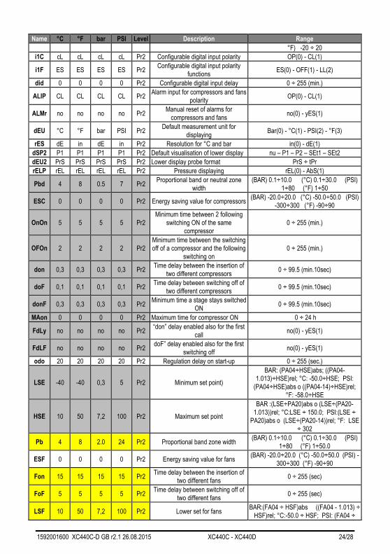
Name °C °F bar PSI Level Description Range
°F) -20 ÷ 20
i1C cL cL cL cL Pr2 Configurable digital input polarity OP(0) - CL(1)
i1F ES ES ES ES Pr2 Configurable digital input polarity
functions ES(0) - OFF(1) - LL(2)
did 0 0 0 0 Pr2 Configurable digital input delay 0 ÷ 255 (min.)
ALIP CL CL CL CL Pr2 Alarm input for compressors and fans
polarity OP(0) - CL(1)
ALMr no no no no Pr2 Manual reset of alarms for
compressors and fans no(0) - yES(1)
dEU °C °F bar PSI Pr2 Default measurement unit for
displaying Bar(0) - °C(1) - PSI(2) - °F(3)
rES dE in dE in Pr2 Resolution for °C and bar in(0) - dE(1)
dSP2 P1 P1 P1 P1 Pr2 Default visualisation of lower display nu – P1 – P2 – SEt1 – SEt2
dEU2 PrS PrS PrS PrS Pr2 Lower display probe format PrS ÷ tPr
rELP rEL rEL rEL rEL Pr2 Pressure displaying rEL(0) - AbS(1)
Pbd 4 8 0.5 7 Pr2 Proportional band or neutral zone
width
(BAR) 0.1÷10.0 (°C) 0.1÷30.0 (PSI)
1÷80 (°F) 1÷50
ESC 0 0 0 0 Pr2 Energy saving value for compressors (BAR) -20.0÷20.0 (°C) -50.0÷50.0 (PSI)
-300÷300 (°F) -90÷90
OnOn 5 5 5 5 Pr2
Minimum time between 2 following
switching ON of the same
compressor
0 ÷ 255 (min.)
OFOn 2 2 2 2 Pr2
Minimum time between the switching
off of a compressor and the following
switching on
0 ÷ 255 (min.)
don 0,3 0,3 0,3 0,3 Pr2 Time delay between the insertion of
two different compressors 0 ÷ 99.5 (min.10sec)
doF 0,1 0,1 0,1 0,1 Pr2 Time delay between switching off of
two different compressors 0 ÷ 99.5 (min.10sec)
donF 0,3 0,3 0,3 0,3 Pr2 Minimum time a stage stays switched
ON 0 ÷ 99.5 (min.10sec)
MAon 0 0 0 0 Pr2 Maximum time for compressor ON 0 ÷ 24 h
FdLy no no no no Pr2 “don” delay enabled also for the first
call no(0) - yES(1)
FdLF no no no no Pr2 doF” delay enabled also for the first
switching off no(0) - yES(1)
odo 20 20 20 20 Pr2 Regulation delay on start-up 0 ÷ 255 (sec.)
LSE -40 -40 0,3 5 Pr2 Minimum set point)
BAR: (PA04÷HSE)abs; ((PA04-
1.013)÷HSE)rel; °C: -50.0÷HSE; PSI:
(PA04÷HSE)abs o ((PA04-14)÷HSE)rel;
°F: -58.0÷HSE
HSE 10 50 7,2 100 Pr2 Maximum set point
BAR :(LSE÷PA20)abs o (LSE÷(PA20-
1.013))rel; °C:LSE ÷ 150.0; PSI:(LSE ÷
PA20)abs o (LSE÷(PA20-14))rel; °F: LSE
÷ 302
Pb 4 8 2.0 24 Pr2 Proportional band zone width (BAR) 0.1÷10.0 (°C) 0.1÷30.0 (PSI)
1÷80 (°F) 1÷50.0
ESF 0 0 0 0 Pr2 Energy saving value for fans (BAR) -20.0÷20.0 (°C) -50.0÷50.0 (PSI) -
300÷300 (°F) -90÷90
Fon 15 15 15 15 Pr2 Time delay between the insertion of
two different fans 0 ÷ 255 (sec)
FoF 5 5 5 5 Pr2 Time delay between switching off of
two different fans 0 ÷ 255 (sec)
LSF 10 50 7,2 100 Pr2 Lower set for fans BAR:(FA04 ÷ HSF)abs ((FA04 - 1.013) ÷
HSF)rel; °C:-50.0 ÷ HSF; PSI: (FA04 ÷

1592001600 XC440C-D GB r2.1 26.08.2015 XC440C - XC440D 25/28
Name °C °F bar PSI Level Description Range
HSF)abs o ((FA04-14) ÷ HSF)rel; °F: -58.0
÷ HSF
HSF 60 140 27,8 404 Pr2 Higher set for fans
BAR : (LSF ÷ F20)abs (LSF ÷ (F20-
1.013))rel; °C:LSF ÷ 150.0; PSI: (LSF ÷
FA20)abs o (LSF÷(FA20 - 14))rel; °F: LSF
÷ 302
PAO 30 30 30 30 Pr2 Alarm probe exclusion at power on 0 ÷ 255 (min.)
LAL 15,0 30 1,5 21 Pr1 Low pressure (temperature) alarm –
compressor section
(0.1 ÷ 30.0)BAR (0.1 ÷ 100.0)°C (1 ÷
430)PSI (1 ÷ 200.0)°F
HAL 20.0 40 2,5 46 Pr1 High pressure (temperature) alarm–
compressor section
(0.1 ÷ 30.0)BAR (0.1 ÷ 100.0)°C (1 ÷
430)PSI (1 ÷ 200.0)°F
tAo 15 15 15 15 Pr1 Low and High pressure (temperature)
alarms delay– compressor section 0 ÷ 255 (min.)
SEr 999 999 999 999 Pr2 Service request 1 ÷ 999 (0= ESCLUSO) (10 ore)
SPr 2 2 2 2 Pr2 number of steps engaged with faulty
probe 0 ÷ (nCPR)
PoPr 50 50 50 50 Pr2 capacity engaged with faulty probe 0 ÷ 100 (%)
LAF 20 40 6,7 96 Pr1 Low pressure alarm – fans section (0.1 ÷ 30.0)BAR (0.1 ÷ 100.0)°C (1 ÷
430)PSI (1 ÷ 200.0)°F
HAF 20 40 9,8 141 Pr1 High pressure alarm – fans section (0.1 ÷ 30.0)BAR (0.1 ÷ 100.0)°C (1 ÷
430)PSI (1 ÷ 200.0)°F
AFd 15 15 15 15 Pr2 Low and High pressure alarms delay
– fans section 0 ÷ 255 (min)
FPr 2 2 2 2 Pr2 Number of fans engaged with faulty
probe 0 ÷ (nFAN)
LAO 0 0 0 0 Pr2 Start of scale for analog output
AOC=Pb : 0.0÷51.0(BAR) -
50.0÷150.0(°C) 0÷750(PSI) -
58÷302(°F);
UAO 1 1 1 1 Pr2 End of scale for analog output
AOC=Pb : 0.0÷51.0(BAR) -
50.0÷150.0(°C) 0÷750(PSI) -
58÷302(°F)
AOM 4 4 4 4 Pr2 Minimum value for analog output 4 ÷ 20
SAO 4 4 4 4 Pr2 Percentage of analog output in case
of probe failure 0 ÷ 100 (%)
tbA yES yES yES yES Pr2 Alarm relay silencing no(0) - yES(1)
OAP cL cL cL cL Pr2 Alarm relay output polarity cL ÷ oP
oFF no no no no Pr2 Switching ON/OFF enabling from
keyboard no(0) - yES(1)
Ad1 1 1 1 1 Pr2 Compressors address 1 ÷ 247
Ad2 1 1 1 1 Pr2 Fans address 1 ÷ 247
rEL Pr1 Software release read only
Ptb Pr1 Parameter table code read only
Pr2 Pr1 Protected parameter menu read only
1592001600 XC440C-D GB r2.1 26.08.2015 XC440C - XC440D 26/28
NOTE

1592001600 XC440C-D GB r2.1 26.08.2015 XC440C - XC440D 27/28

1592001600 XC440C-D GB r2.1 26.08.2015 XC440C - XC440D 28/28