
XBee/XBee-PRO DigiMesh 2.4 RF Module User Guide · TransparentandAPIoperatingmodes 26...
157
XBee/XBee-PRO DigiMesh 2.4 Radio Frequency (RF) Module User Guide
Transcript of XBee/XBee-PRO DigiMesh 2.4 RF Module User Guide · TransparentandAPIoperatingmodes 26...
XBee/XBee-PRO DigiMesh 2.4Radio Frequency (RF) Module
User Guide

Revision history—90000991
Revision Date Description
S January2016
Updated several AT commands.
T February2016
Editorial revision to AT commands.
U June 2016 Removed the 1S command. Fixed an error in the 0x90 frame table. Clarifiedthe routing table size.
V June 2017 Modified regulatory and certification information as required by RED (RadioEquipment Directive).
W May 2018 Added note on range estimation. Changed IC to ISED.
Trademarks and copyrightDigi, Digi International, and the Digi logo are trademarks or registered trademarks in the UnitedStates and other countries worldwide. All other trademarks mentioned in this document are theproperty of their respective owners.© 2018 Digi International Inc. All rights reserved.
DisclaimersInformation in this document is subject to change without notice and does not represent acommitment on the part of Digi International. Digi provides this document “as is,” without warranty ofany kind, expressed or implied, including, but not limited to, the implied warranties of fitness ormerchantability for a particular purpose. Digi may make improvements and/or changes in this manualor in the product(s) and/or the program(s) described in this manual at any time.
WarrantyTo view product warranty information, go to the following website:www.digi.com/howtobuy/terms
Send commentsDocumentation feedback: To provide feedback on this document, send your comments [email protected].
Customer supportDigi Technical Support: Digi offers multiple technical support plans and service packages to help ourcustomers get the most out of their Digi product. For information on Technical Support plans andpricing, contact us at +1 952.912.3444 or visit us at www.digi.com/support.
XBee/XBee-PRO DigiMesh 2.4 RF Module User Guide 2
Contents
XBee/XBee-PRO DigiMesh 2.4 RF Module User GuideWorldwide acceptance 10Antenna options 10Part numbers 10
Technical specificationsPerformance specifications 12Power requirements 12General specifications 13Networking and security specifications 13Regulatory conformity summary 13
HardwareMechanical drawings 16Mounting considerations 17Hardware diagram 18Pin signals 19
Notes 20Recommended pin connections 20
Design notes 20Power supply design 20Board layout 20Antenna performance 21Keepout area 21
DC characteristics 23ADC operating characteristics 23ADC timing and performance characteristics 24
ModesTransparent and API operating modes 26
Transparent operating mode 26API operating mode 26Comparing Transparent and API modes 26
Additional modes 28Commandmode 28Idle mode 28
XBee/XBee-PRO DigiMesh 2.4 RF Module User Guide 3
XBee/XBee-PRO DigiMesh 2.4 RF Module User Guide 4
Receive mode 28Sleepmodes 28Transmit mode 29
Enter Commandmode 29Troubleshooting 29
Send AT commands 29Exit Commandmode 30
Configure the XBee/XBee-PRO DigiMesh 2.4Software libraries 32Configure the device using XCTU 32
Serial communicationSerial interface 34UART data flow 34
Serial data 34Serial buffers 35
Serial buffer issues 35Serial flow control 36
CTS flow control 36RTS flow control 36
Work with networked devicesNetwork commissioning and diagnostics 38
Local configuration 38Remote configuration 38
Establish andmaintain network links 39Build aggregate routes 39DigiMesh routing examples 39Replace nodes 40
Test links in a network - loopback cluster 40Test links between adjacent devices 41
Example 42RSSI indicators 43Discover all the devices on a network 43Trace route option 43NACK messages 44The Commissioning Pushbutton 45Associate LED 46
Monitor I/O lines 48Queried sampling 48Periodic I/O sampling 50Detect digital I/O changes 50
Network configurationsDigiMesh networking 53
Routers and end devices 54Network identifiers 54
Operating channels 54
XBee/XBee-PRO DigiMesh 2.4 RF Module User Guide 5
Unicast addressing 54Broadcast addressing 55
Routing 55Route discovery 55DigiMesh throughput 56Transmission timeouts 56
Sleep modesAbout sleepmodes 59
Asynchronous modes 59Synchronous modes 59
Normal mode 59Asynchronous pin sleepmode 60Asynchronous cyclic sleepmode 60Asynchronous cyclic sleep with pin wake upmode 60Synchronous sleep support mode 60Synchronous cyclic sleepmode 61The sleep timer 61Sleep coordinator sleepmodes in the DigiMesh network 61Synchronization messages 62Become a sleep coordinator 64
Preferred sleep coordinator option 64Resolution criteria and selection option 64Commissioning Pushbutton option 65Auto-early wake-up sleep option 66
Select sleep parameters 66Start a sleeping synchronous network 66Add a new node to an existing network 67Change sleep parameters 68Rejoin nodes that lose sync 68Diagnostics 69
Query sleep cycle 69Sleep status 69Missed sync messages command 70Sleep status API messages 70
AT commandsSpecial commands 72
AC (Apply Changes) 72FR (Software Reset) 72RE command 72WR command 72
MAC/PHY commands 73CH (Operating Channel) 73ID (Network ID) 73MT (Broadcast Multi-Transmits) 73CA (CCA Threshold) 74PL (TX Power Level) 74RR (Unicast Mac Retries) 75ED (Energy Detect) 75BC (Bytes Transmitted) 75DB (Last Packet RSSI) 76
XBee/XBee-PRO DigiMesh 2.4 RF Module User Guide 6
GD (Good Packets Received) 76EA (MAC ACK Failure Count) 76TR (Transmission Failure Count) 77UA (Unicasts Attempted Count) 77%H (MAC Unicast One Hop Time) 77%8 (MAC Broadcast One Hop Time) 77
Network commands 77CE (Routing / Messaging Mode) 78BH command 78NH (Network Hops) 78DM (DigiMesh Options) 78NN (Network Delay Slots) 79MR (Mesh Unicast Retries) 79
Addressing commands 79SH command 79SL command 80DH command 80DL command 80NI command 80NT (Network Discovery Back-off) 81NO (Network Discovery Options) 81CI (Cluster ID) 82DE command 82SE command 82
Diagnostic - addressing commands 82N? (Network Discovery Timeout) 82
Addressing discovery/configuration commands 83AG (Aggregator Support) 83DN (Discover Node) 83ND (Network Discover) 84FN (Find Neighbors) 84
Security commands 85EE (Encryption Enable) 85KY (AES Encryption Key) 85
Serial interfacing commands 85BD (Baud Rate) 85NB (Parity) 86RO command 86FT (Flow Control Threshold) 87API Mode 87AO command 87
I/O settings commands 88CB command 88D0 (DIO0/AD0) 88D1 (DIO1/AD1) 89D2 (DIO2/AD2) 89D3 (DIO3/AD3) 89D4 (DIO4/AD4) 90D5 (DIO5/AD5/ASSOCIATED_INDICATOR) 90D6 (DIO6/RTS) 91D7 (DIO7/CTS) 91D8 (DIO8/SLEEP_REQUEST) 92D9 (ON_SLEEP) 92P0 (DIO10/RSSI/PWM0 Configuration) 93P1 (DIO11/PWM1 Configuration) 93

XBee/XBee-PRO DigiMesh 2.4 RF Module User Guide 7
P2 (DIO12 Configuration) 94PR (Pull-up/Down Resistor Enable) 94M0 (PWM0 Duty Cycle) 95M1 (PWM1 Duty Cycle) 95LT command 96RP command 96
I/O sampling commands 96IC (DIO Change Detect) 96IF (Sleep Sample Rate) 97IR (Sample Rate) 97IS command 98
Sleep commands 98SM command 98SO command 99SN command 100SP (Sleep Time) 100ST (Wake Time) 100WH (Wake Host Delay) 101
Diagnostic - sleep status/timing commands 101SS (Sleep Status) 101OS (Operating Sleep Time) 102OW (Operating Wake Time) 102MS (Missed Sync Messages) 102SQ (Missed Sleep Sync Count) 102
Commandmode options 103CC (Command Character) 103CT command 103CN command 103GT command 103
Firmware version/information commands 104VL command 104VR command 104HV command 104DD command 104NP (Maximum Packet Payload Bytes) 105CK (Configuration CRC) 105
Operate in API modeAPI mode overview 107
API frame specifications 107Calculate and verify checksums 109Escaped characters in API frames 110
Frame descriptions 111API frame exchanges 111Code to support future API frames 113AT Command frame - 0x08 114AT Command - Queue Parameter Value frame - 0x09 115Transmit Request frame - 0x10 117Explicit Addressing Command frame - 0x11 120Remote AT Command Request frame - 0x17 123AT Command Response frame - 0x88 125Modem Status frame - 0x8A 126Transmit Status frame - 0x8B 127Route Information Packet frame - 0x8D 129

XBee/XBee-PRO DigiMesh 2.4 RF Module User Guide 8
Aggregate Addressing Update frame - 0x8E 132Receive Packet frame - 0x90 134Explicit Rx Indicator frame - 0x91 136Data Sample Rx Indicator frame - 0x92 138Node Identification Indicator frame - 0x95 140Remote Command Response frame - 0x97 143
Regulatory informationUnited States (FCC) 146
OEM labeling requirements 146FCC notices 146RF exposure statement 147FCC-approved antennas (2.4 GHz) 147
Australia (C-Tick) 153Labeling requirements 153
Brazil ANATEL 153Modelo XBee-Pro S3B: 154
ISED (Innovation, Science and Economic Development Canada) 154Labeling requirements 154
Europe 154Maximum power and frequency specifications 155OEM labeling requirements 155Restrictions 155Declarations of conformity 155Approved antennas 156
Japan 156Labeling requirements 156
XBee/XBee-PRO DigiMesh 2.4 RF Module User Guide
The XBee/XBee-PRO DigiMesh 2.4 supports the unique needs of low-cost, low-power, wireless sensornetworks. The devices require minimal power and provide reliable data delivery between remotedevices. The devices operate within the ISM 2.4 MHz frequency band.These devices support routing table sizes of 32 nodes. Networks larger than this send a routediscovery before each transmission. For larger networks this can be bandwidth expensive, so we offerRF optimization services to help you properly configure a network.
Worldwide acceptance 10Antenna options 10Part numbers 10
XBee/XBee-PRO DigiMesh 2.4 RF Module User Guide 9
XBee/XBee-PRO DigiMesh 2.4 RF Module User Guide Worldwide acceptance
XBee/XBee-PRO DigiMesh 2.4 RF Module User Guide 10
Worldwide acceptanceWe manufacture and certify the XBee/XBee-PRO DigiMesh 2.4s to certain industry standards. Thesestandards enable you to understand what the devices can do and where you can use them.The Federal Communications Commission (FCC) approves the devices for use in the United States. Fordetails, see United States (FCC). If a system contains XBee/XBee-PRO DigiMesh 2.4s, the systeminherits Digi’s certifications.The devices are certified to operate in the industrial, scientific, andmedical (ISM) 2.4 GHz frequencyband.We manufacture the devices under International Organization for Standardization (ISO) 9001:2000registered standards.We optimize the devices for use in the United States and Canada. For a complete list of agencyapprovals, see Regulatory information.
Antenna optionsDigi devices come in a variety of antenna options. The options that allow you to connect an externalantenna are reverse polarity standard subminiature assembly (RPSMA) and U.FL. Typically, you makeconnections with either a dipole antenna with a U.FL connection, or a U.FL to RPSMA antenna adaptercable.RPSMA is the more traditional antenna connector, however, if the device is going to be inside of anenclosure, you would need to locate the device near the edge of the enclosure to allow the connectorto pass through an available bulkhead. The RPSMA connector uses the same body as a regular SMAconnector, but changes the gender of the center conductor. The female RPSMA actually has a malecenter conductor. We equip the XBee devices with an RPSMA female plug, while the antenna is anRPSMAmale jack.The U.FL connection allows for connectivity to an external antenna. U.FL is a small antenna connectionfor use with a pigtail connector. A pigtail is a short (typically 4 - 6 in) cable that either terminates intoan external antenna port such as an RPSMA, N or TNC connection or an antenna. You would attach theRPSMA connector to a bulkhead. These options allow you to mount the device away from the edge ofthe enclosure in your product and centrally locate the radio. U.FL is fragile and is not designed formultiple insertions without a specialized tool to separate the pigtail without damaging the connector;for more information, see http://www.digikey.com/product-detail/en/U.FL-LP(V)-N-2/HR5017-ND/513034.The other available antenna options are printed circuit board (PCB) and wire antennas. We form thePCB antenna directly on the device with conductive traces. A PCB antenna performs about the sameas a wire antenna.An integrated wire antenna consists of a small wire (about 80 mm) sticking up perpendicular to thePCB. It uses a 1/4-wave wire that we solder directly to the PCB of the OEM device.All Digi devices with antenna connectors have less than 0.1 dB loss; we do not consider one to be"better" than the other in terms of reliability or insertion loss. RF device specifications such as -110dBm receiver sensitivity, +3 0 dBm TX power, and so forth, already include any insertion loss due tothe soldered RF connector.
Part numbersThe part numbers for these devices are available at the following link:www.digi.com/products/xbee-rf-solutions/modules/xbee-digimesh-2-4#partnumbers
Technical specifications
The following tables provide the device's technical specifications.
Performance specifications 12Power requirements 12General specifications 13Networking and security specifications 13Regulatory conformity summary 13
XBee/XBee-PRO DigiMesh 2.4 RF Module User Guide 11
Technical specifications Performance specifications
XBee/XBee-PRO DigiMesh 2.4 RF Module User Guide 12
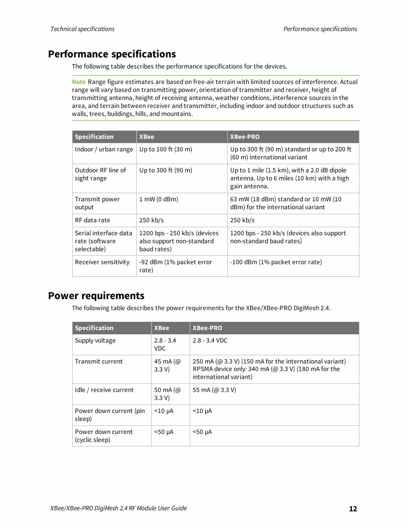
Performance specificationsThe following table describes the performance specifications for the devices.
Note Range figure estimates are based on free-air terrain with limited sources of interference. Actualrange will vary based on transmitting power, orientation of transmitter and receiver, height oftransmitting antenna, height of receiving antenna, weather conditions, interference sources in thearea, and terrain between receiver and transmitter, including indoor and outdoor structures such aswalls, trees, buildings, hills, andmountains.
Specification XBee XBee-PRO
Indoor / urban range Up to 100 ft (30 m) Up to 300 ft (90 m) standard or up to 200 ft(60 m) international variant
Outdoor RF line ofsight range
Up to 300 ft (90 m) Up to 1 mile (1.5 km), with a 2.0 dB dipoleantenna. Up to 6 miles (10 km) with a highgain antenna.
Transmit poweroutput
1 mW (0 dBm) 63 mW (18 dBm) standard or 10 mW (10dBm) for the international variant
RF data rate 250 kb/s 250 kb/s
Serial interface datarate (softwareselectable)
1200 bps - 250 kb/s (devicesalso support non-standardbaud rates)
1200 bps - 250 kb/s (devices also supportnon-standard baud rates)
Receiver sensitivity -92 dBm (1% packet errorrate)
-100 dBm (1% packet error rate)
Power requirementsThe following table describes the power requirements for the XBee/XBee-PRO DigiMesh 2.4.
Specification XBee XBee-PRO
Supply voltage 2.8 - 3.4VDC
2.8 - 3.4 VDC
Transmit current 45 mA (@3.3 V)
250 mA (@ 3.3 V) (150 mA for the international variant)RPSMA device only: 340 mA (@ 3.3 V) (180 mA for theinternational variant)
Idle / receive current 50 mA (@3.3 V)
55 mA (@ 3.3 V)
Power down current (pinsleep)
<10 µA <10 µA
Power down current(cyclic sleep)
<50 µA <50 µA

Technical specifications General specifications
XBee/XBee-PRO DigiMesh 2.4 RF Module User Guide 13
General specificationsThe following table describes the general specifications for the devices.
Specification XBee XBee-PRO
Operating frequencyband
ISM 2.4 GHz ISM 2.4 GHz
Dimensions 2.438 cm x 2.761 cm (0.960 in x 1.087 in) 2.438 cm x 3.294 cm (0.960 inx 1.297 in)
Operating temperature -40 to 85 °C (industrial) -40 to 85 °C (industrial)
Relative humidity 0 to 95% non-condensing 0 to 95% non-condensing
Antenna options 1/4 wave wire antenna, embedded PCBantenna, RPSMA RF connector, U.FL RFconnector
1/4 wave wire antenna,RPSMA RF connector, U.FL RFconnector
Networking and security specificationsThe following table describes the networking and security specifications for the devices.
Specification XBee XBee-PRO
Supported networktopologies
Mesh, point-to-point, point-to-multipoint, peer-to-peer
Mesh, point-to-point, point-to-multipoint, peer-to-peer
Number of channels(software selectable)
16 direct sequence channels 12 direct sequence channels
Addressing options PAN ID, channel and 64-bitaddresses
PAN ID, channel and 64-bitaddresses
Encryption 128 bit Advanced EncryptionStandard (AES)
128 bit AES
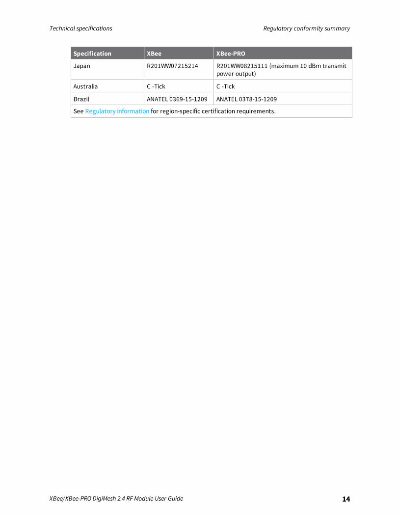
Regulatory conformity summaryThis table describes the agency approvals for the devices.
Specification XBee XBee-PRO
United States (FCC Part15.247)
OUR-XBEE OUR-XBEEPRO
Industry Canada (IC) 4214A-XBEE 4214A-XBEEPRO
Europe (CE) Yes Yes (maximum 10 dBm transmit power output)
RoHS Lead-free and RoHScompliant
Lead-free and RoHS compliant
Technical specifications Regulatory conformity summary
XBee/XBee-PRO DigiMesh 2.4 RF Module User Guide 14
Specification XBee XBee-PRO
Japan R201WW07215214 R201WW08215111 (maximum 10 dBm transmitpower output)
Australia C -Tick C -Tick
Brazil ANATEL 0369-15-1209 ANATEL 0378-15-1209
See Regulatory information for region-specific certification requirements.
Hardware
Mechanical drawings 16Mounting considerations 17Hardware diagram 18Pin signals 19Design notes 20DC characteristics 23ADC operating characteristics 23ADC timing and performance characteristics 24
XBee/XBee-PRO DigiMesh 2.4 RF Module User Guide 15
Hardware Mechanical drawings
XBee/XBee-PRO DigiMesh 2.4 RF Module User Guide 16
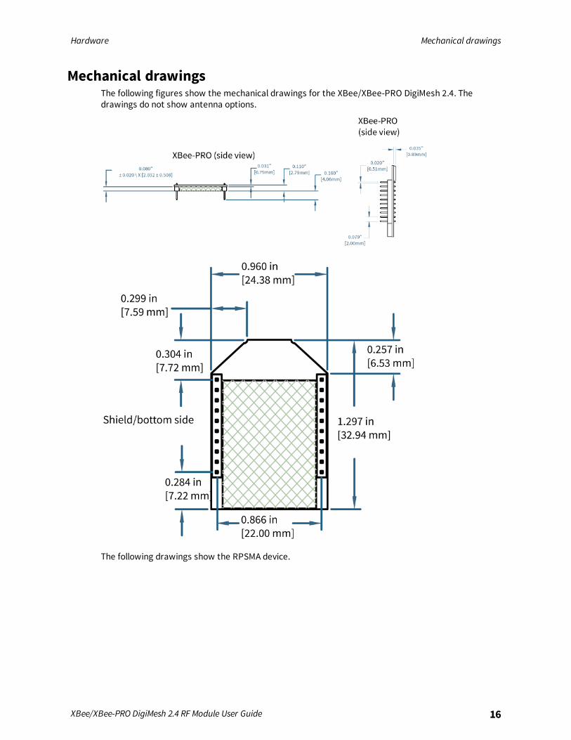
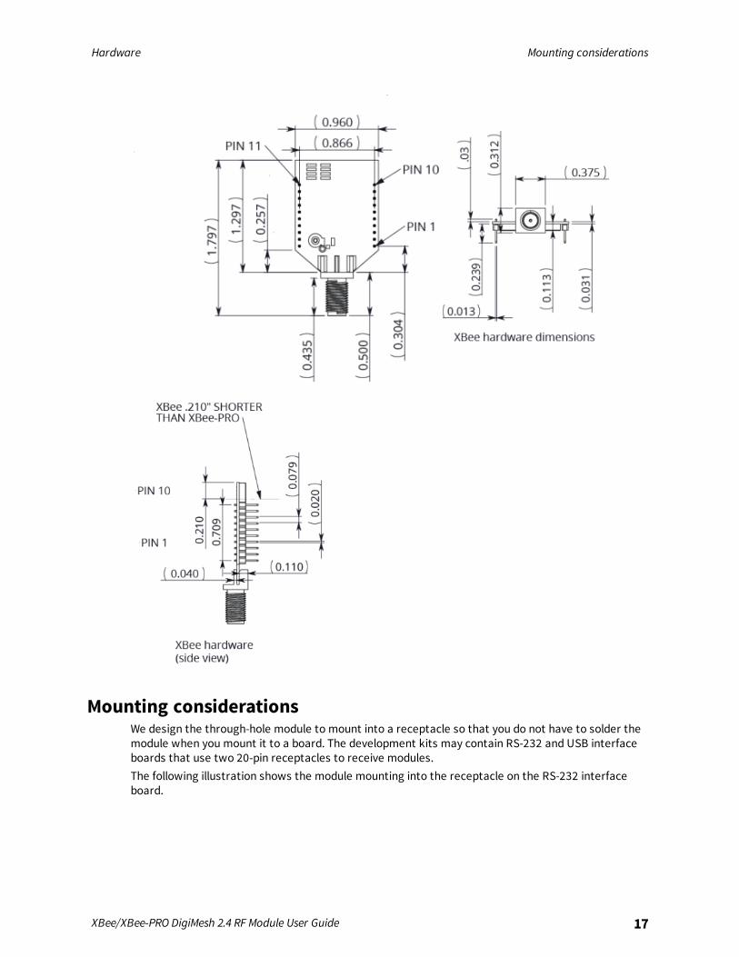
Mechanical drawingsThe following figures show the mechanical drawings for the XBee/XBee-PRO DigiMesh 2.4. Thedrawings do not show antenna options.
The following drawings show the RPSMA device.
Hardware Mounting considerations
XBee/XBee-PRO DigiMesh 2.4 RF Module User Guide 17
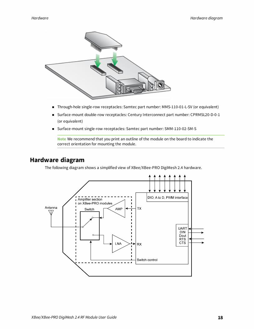
Mounting considerationsWe design the through-hole module to mount into a receptacle so that you do not have to solder themodule when you mount it to a board. The development kits may contain RS-232 and USB interfaceboards that use two 20-pin receptacles to receive modules.The following illustration shows the module mounting into the receptacle on the RS-232 interfaceboard.
Hardware Hardware diagram
XBee/XBee-PRO DigiMesh 2.4 RF Module User Guide 18
n Through-hole single-row receptacles: Samtec part number: MMS-110-01-L-SV (or equivalent)
n Surface-mount double-row receptacles: Century Interconnect part number: CPRMSL20-D-0-1(or equivalent)
n Surface-mount single-row receptacles: Samtec part number: SMM-110-02-SM-S
Note We recommend that you print an outline of the module on the board to indicate thecorrect orientation for mounting the module.
Hardware diagramThe following diagram shows a simplified view of XBee/XBee-PRO DigiMesh 2.4 hardware.

Hardware Pin signals
XBee/XBee-PRO DigiMesh 2.4 RF Module User Guide 19
Pin signalsThe following table shows the pin signals and their descriptions.
Pin# Pin name Direction Description
1 Vcc - Power supply
2 DOUT Output UART data out
3 DIN/CONFIG Input UART data in
4 DIO12 Either Digital I/O 12
5 RESET Input/opendrainoutput
Device reset. The reset pulse must be at least 100 µs.Drive this line as an open drain/collector. The devicedrives this line low when a reset occurs. Never drive thisline high.
6 PWM0/RSSI/DIO10 Either PWM output 0 / RX signal strength indicator / Digital I/O
7 PWM/DIO11 Either PWM output 1 / Digital I/O 11
8 Reserved - Do not connect
9 DTR / SLEEP_RQ / DIO8
Either Pin sleep control line or Digital I/O 8
10 GND - Ground
11 AD4/ DIO4 Either Analog input 4 or Digital I/O 4
12 CTS/ DIO7 Either Clear-to-send flow control or Digital I/O 7
13 ON/SLEEP Output Device Status Indicator or Digital I/O 9
14 VREF - You must connect this line if you want to use analog I/Osampling. Must be between 2.6 V and Vcc.
15 Associate / DIO5/ AD5 Either Associated indicator, Digital I/O 5
16 RTS/ DIO6 Either Request-to-send flow control, Digital I/O 6
17 AD3 / DIO3 Either Analog input 3 or Digital I/O 3
18 AD2 / DIO2 Either Analog input 2 or Digital I/O 2
Hardware Design notes
XBee/XBee-PRO DigiMesh 2.4 RF Module User Guide 20
Pin# Pin name Direction Description
19 AD1 / DIO1 Either Analog input 1 or Digital I/O 1
20 AD0 / DIO0 /CommissioningPushbutton
Either Analog input 0, Digital I/O 0, or CommissioningPushbutton
NotesThe table specifies signal direction with respect to the device.The device includes a 50 kΩpull-up resistor attached to RESET.You can configure several of the input pull-ups using the PR command.Leave any unused pins disconnected.
Recommended pin connectionsThe only required pin connections for two-way communication are VCC, GND, DOUT and DIN. Tosupport serial firmware updates, you must connect VCC, GND, DOUT, DIN, RTS, and DTR.Do not connect any pins that are not in use. Use the PR command to pull all inputs on the radio highwith internal pull-up resistors. Unused outputs do not require any specific treatment.For applications that need to ensure the lowest sleep current, never leave unconnected inputsfloating. Use internal or external pull-up or pull-down resistors, or set the unused I/O lines to outputs.You can connect other pins to external circuitry for convenience of operation including the AssociateLED pin (pin 15) and the Commissioning pin (pin 20). The Associate LED pin flashes differentlydepending on the state of the module, and a pushbutton attached to pin 20 can enable variousdeployment and troubleshooting functions without you sending UART commands. For moreinformation, see The Commissioning Pushbutton.For analog sampling, attach the VREF pin (pin 14) to a voltage reference.
Design notesThe following guidelines help to ensure a robust design.
Power supply designA poor power supply can lead to poor device performance, especially if you do not keep the supplyvoltage within tolerance or if it is excessively noisy. To help reduce noise, place a 1.0 μF and 8.2 pFcapacitor as near as possible to pin 1 on the PCB. If you are using a switching regulator for the powersupply, switch the frequencies above 500 kHz. Limit the power supply ripple to a maximum 100 mVpeak to peak.
Board layoutWe design XBee devices to be self sufficient and have minimal sensitivity to nearby processors,crystals or other printed circuit board (PCB) components. Keep power and ground traces thicker thansignal traces andmake sure that they are able to comfortably support the maximum currentspecifications. There are no other special PCB design considerations to integrate XBee devices, withthe exception of antennas.

Hardware Design notes
XBee/XBee-PRO DigiMesh 2.4 RF Module User Guide 21
Antenna performanceAntenna location is important for optimal performance. The following suggestions help you achieveoptimal antenna performance. Point the antenna up vertically (upright). Antennas radiate and receivethe best signal perpendicular to the direction they point, so a vertical antenna's omnidirectionalradiation pattern is strongest across the horizon.Position the antennas away from metal objects whenever possible. Metal objects between thetransmitter and receiver can block the radiation path or reduce the transmission distance. Objectsthat are often overlooked include:
n metal poles
n metal studs
n structure beams
n concrete, which is usually reinforced with metal rods
If you place the device inside a metal enclosure, use an external antenna. Common objects that havemetal enclosures include:
n vehicles
n elevators
n ventilation ducts
n refrigerators
n microwave ovens
n batteries
n tall electrolytic capacitors
Do not place XBee devices with the chip or integrated PCB antenna inside a metal enclosure.Do not place any ground planes or metal objects above or below the antenna.For the best results, mount the device at the edge of the host PCB. Ensure that the ground, power,and signal planes are vacant immediately below the antenna section.
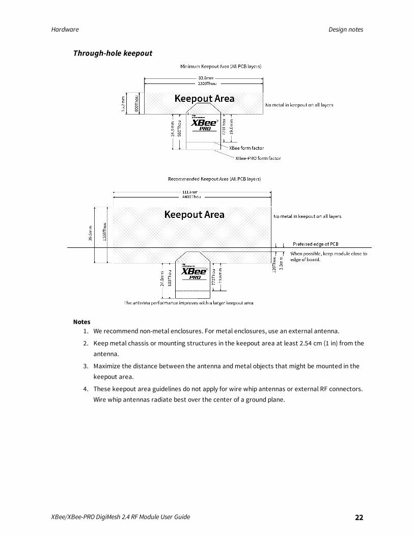
Keepout areaWe recommend that you allow a “keepout” area, as shown in the following drawing.
Hardware Design notes
XBee/XBee-PRO DigiMesh 2.4 RF Module User Guide 22
Through-hole keepout
Notes1. We recommend non-metal enclosures. For metal enclosures, use an external antenna.
2. Keepmetal chassis or mounting structures in the keepout area at least 2.54 cm (1 in) from theantenna.
3. Maximize the distance between the antenna andmetal objects that might be mounted in thekeepout area.
4. These keepout area guidelines do not apply for wire whip antennas or external RF connectors.Wire whip antennas radiate best over the center of a ground plane.
Hardware DC characteristics
XBee/XBee-PRO DigiMesh 2.4 RF Module User Guide 23
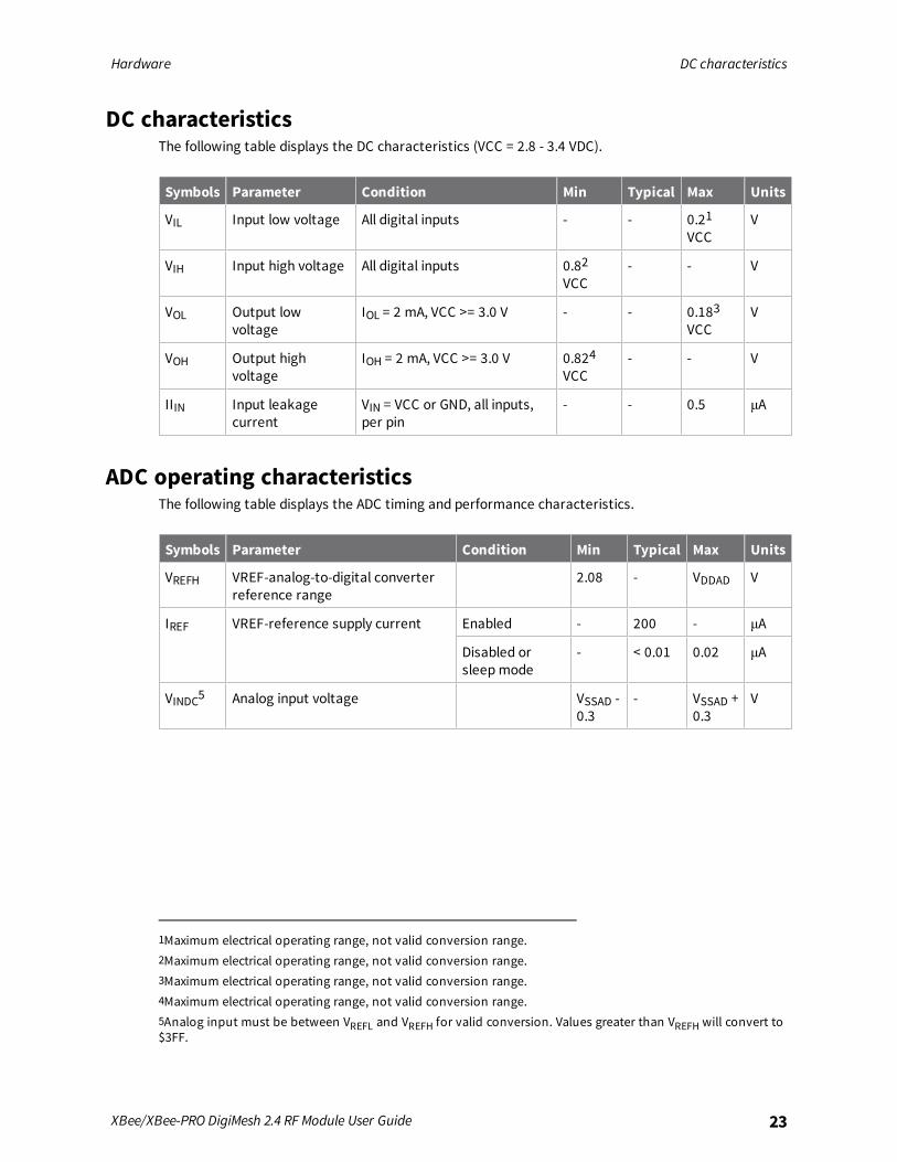
DC characteristicsThe following table displays the DC characteristics (VCC = 2.8 - 3.4 VDC).
Symbols Parameter Condition Min Typical Max Units
VIL Input low voltage All digital inputs - - 0.21VCC
V
VIH Input high voltage All digital inputs 0.82VCC
- - V
VOL Output lowvoltage
IOL = 2 mA, VCC >= 3.0 V - - 0.183VCC
V
VOH Output highvoltage
IOH = 2 mA, VCC >= 3.0 V 0.824VCC
- - V
IIIN Input leakagecurrent
VIN = VCC or GND, all inputs,per pin
- - 0.5 μA
ADC operating characteristicsThe following table displays the ADC timing and performance characteristics.
Symbols Parameter Condition Min Typical Max Units
VREFH VREF-analog-to-digital converterreference range
2.08 - VDDAD V
IREF VREF-reference supply current Enabled - 200 - μA
Disabled orsleepmode
- < 0.01 0.02 μA
VINDC5 Analog input voltage VSSAD -0.3
- VSSAD +0.3
V
1Maximum electrical operating range, not valid conversion range.2Maximum electrical operating range, not valid conversion range.3Maximum electrical operating range, not valid conversion range.4Maximum electrical operating range, not valid conversion range.5Analog input must be between VREFL and VREFH for valid conversion. Values greater than VREFH will convert to$3FF.
Hardware ADC timing and performance characteristics
XBee/XBee-PRO DigiMesh 2.4 RF Module User Guide 24
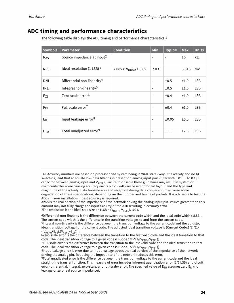
ADC timing and performance characteristicsThe following table displays the ADC timing and performance characteristics.1
Symbols Parameter Condition Min Typical Max Units
RAS Source impedance at input2 - - 10 kΩ
RES Ideal resolution (1 LSB)3 2.08V > VDDAD > 3.6V 2.031 3.516 mV
DNL Differential non-linearity4 - ±0.5 ±1.0 LSB
INL Integral non-linearity5 - ±0.5 ±1.0 LSB
EZS Zero-scale error6 - ±0.4 ±1.0 LSB
FFS Full-scale error7 - ±0.4 ±1.0 LSB
EIL Input leakage error8 - ±0.05 ±5.0 LSB
ETU Total unadjusted error9 - ±1.1 ±2.5 LSB
1All Accuracy numbers are based on processor and system being in WAIT state (very little activity and no I/Oswitching) and that adequate low-pass filtering is present on analog input pins (filter with 0.01 µF to 0.1 µFcapacitor between analog input and VREFL). Failure to observe these guidelines may result in system ormicrocontroller noise causing accuracy errors which will vary based on board layout and the type andmagnitude of the activity. Data transmission and reception during data conversion may cause somedegradation of these specifications, depending on the number and timing of packets. It is advisable to test theADCs in your installation if best accuracy is required.2RAS is the real portion of the impedance of the network driving the analog input pin. Values greater than thisamount may not fully charge the input circuitry of the ATD resulting in accuracy error.3The resolution is the ideal step size or 1LSB = (VREFH–VREFL)/1024.
4Differential non-linearity is the difference between the current code width and the ideal code width (1LSB).The current code width is the difference in the transition voltages to and from the current code.5Integral non-linearity is the difference between the transition voltage to the current code and the adjustedideal transition voltage for the current code. The adjusted ideal transition voltage is (Current Code.1/2)*(1/((VREFH+EFS).(VREFL+EZS))).6Zero-scale error is the difference between the transition to the first valid code and the ideal transition to thatcode. The Ideal transition voltage to a given code is (Code.1/2)*(1/(VREFH·VREFL)).7Full-scale error is the difference between the transition to the last valid code and the ideal transition to thatcode. The ideal transition voltage to a given code is (Code.1/2)*(1/(VREFH·VREFL)).8Input leakage error is error due to input leakage across the real portion of the impedance of the networkdriving the analog pin. Reducing the impedance of the network reduces this error.9Total unadjusted error is the difference between the transition voltage to the current code and the idealstraight-line transfer function. This measure of error includes inherent quantization error (1/2 LSB) and circuiterror (differential, integral, zero-scale, and full-scale) error. The specified value of ETU assumes zero EIL (noleakage or zero real source impedance).
Modes
The XBee/XBee-PRO DigiMesh 2.4 is in Receive Mode when it is not transmitting data. The deviceshifts into the other modes of operation under the following conditions:
n Transmit mode (Serial data in the serial receive buffer is ready to be packetized)
n Sleepmode
n Command Mode (Commandmode sequence is issued (not available when using the SPI port))
Transparent and API operating modes 26Additional modes 28Enter Commandmode 29Send AT commands 29Exit Commandmode 30
XBee/XBee-PRO DigiMesh 2.4 RF Module User Guide 25
Modes Transparent and API operating modes
XBee/XBee-PRO DigiMesh 2.4 RF Module User Guide 26
Transparent and API operating modesThe firmware operates in several different modes. Two top-level modes establish how the devicecommunicates with other devices through its serial interface: Transparent operating mode and APIoperating mode.
Transparent operating modeDevices operate in this mode by default. The device acts as a serial line replacement when it is inTransparent operating mode. The device queues all UART data it receives through the DIN pin for RFtransmission. When a device receives RF data, it sends the data out through the DOUT pin. You can setthe configuration parameters using the AT Command interface.
API operating modeAPI operating mode is an alternative to Transparent mode. API mode is a frame-based protocol thatallows you to direct data on a packet basis. It can be particularly useful in large networks where youneed control over the operation of the radio network or when you need to know which node a datapacket originated from. The device communicates UART data in packets, also known as API frames.This mode allows for structured communications with serial devices. It is helpful in managing largernetworks and is more appropriate for performing tasks such as collecting data from multiple locationsor controlling multiple devices remotely.For more information, see API frame specifications.
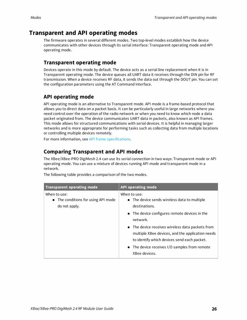
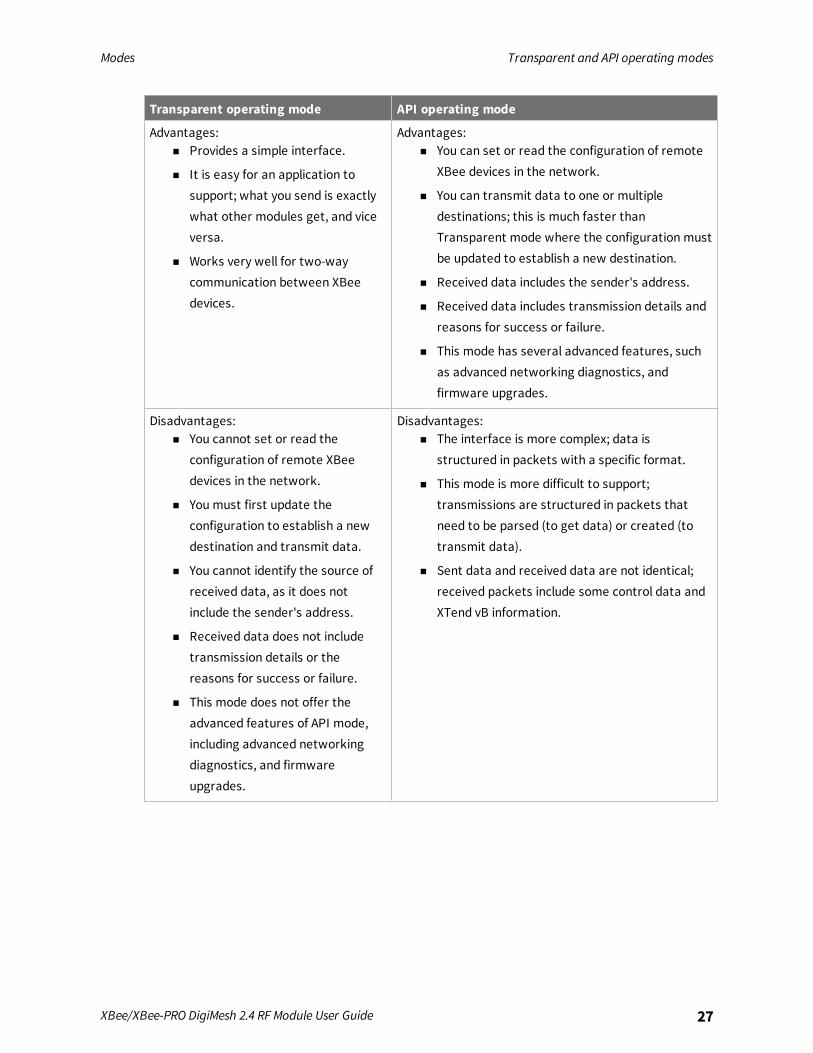
Comparing Transparent and API modesThe XBee/XBee-PRO DigiMesh 2.4 can use its serial connection in two ways: Transparent mode or APIoperating mode. You can use a mixture of devices running API mode and transparent mode in anetwork.The following table provides a comparison of the two modes.
Transparent operating mode API operating mode
When to use:n The conditions for using API mode
do not apply.
When to use:n The device sends wireless data to multiple
destinations.
n The device configures remote devices in thenetwork.
n The device receives wireless data packets frommultiple XBee devices, and the application needsto identify which devices send each packet.
n The device receives I/O samples from remoteXBee devices.
Modes Transparent and API operating modes
XBee/XBee-PRO DigiMesh 2.4 RF Module User Guide 27
Transparent operating mode API operating mode
Advantages:n Provides a simple interface.
n It is easy for an application tosupport; what you send is exactlywhat other modules get, and viceversa.
n Works very well for two-waycommunication between XBeedevices.
Advantages:n You can set or read the configuration of remote
XBee devices in the network.
n You can transmit data to one or multipledestinations; this is much faster thanTransparent mode where the configuration mustbe updated to establish a new destination.
n Received data includes the sender's address.
n Received data includes transmission details andreasons for success or failure.
n This mode has several advanced features, suchas advanced networking diagnostics, andfirmware upgrades.
Disadvantages:n You cannot set or read the
configuration of remote XBeedevices in the network.
n You must first update theconfiguration to establish a newdestination and transmit data.
n You cannot identify the source ofreceived data, as it does notinclude the sender's address.
n Received data does not includetransmission details or thereasons for success or failure.
n This mode does not offer theadvanced features of API mode,including advanced networkingdiagnostics, and firmwareupgrades.
Disadvantages:n The interface is more complex; data is
structured in packets with a specific format.
n This mode is more difficult to support;transmissions are structured in packets thatneed to be parsed (to get data) or created (totransmit data).
n Sent data and received data are not identical;received packets include some control data andXTend vB information.
Modes Additional modes
XBee/XBee-PRO DigiMesh 2.4 RF Module User Guide 28
Additional modesIn addition to the serial communication modes, several modes apply to how devices communicatewith each other.
Command modeCommandmode is a state in which the firmware interprets incoming characters as commands.Commandmode allows you to modify the device’s firmware using parameters you can set using ATcommands. When you want to read or set any setting of the device, you have to send it an ATcommand. Every AT command starts with the letters "AT", followed by the two characters thatidentify the command that is being issued and then by some optional configuration values. For moredetails, see Enter Commandmode.
Idle modeThe device is in Idle mode when it is not receiving or transmitting data. During Idle mode, the devicelistens for valid data on both the RF and serial ports.
Receive modeIf a destination node receives a valid RF packet, the destination node transfers the data to its serialtransmit buffer. For the serial interface to report receive data on the RF network, that data mustmeet the following criteria:
n ID match
n Channel match
n Address match
Sleep modesSleepmodes allows the device to enter states of low power consumption when not in use. The deviceis almost completely off during sleep, and is incapable of sending or receiving data until it wakes up.XBee devices support both pin sleep, where the module enters sleepmode upon pin transition, andcyclic sleep, where the module sleeps for a fixed time. While asleep, nodes cannot receive RFmessages or read commands from the UART port.The sleepmodes are:
n Normal mode. Normal mode is the default for a newly powered-on node. In this mode, a nodedoes not sleep. Normal mode nodes should be mains-powered.
n Asynchronous Pin Sleepmode. This mode allows the device to sleep and wake according to thestate of the Sleep_RQ pin (pin 9).
n Asynchronous Cyclic Sleep Mode. This mode allows the device to sleep for a specified time andwake for a short time to poll.
n Asynchronous Cyclic Sleep with Pin Wake Upmode. In this mode you can wake the device upprematurely using the Sleep_RQ pin.
Modes Enter Command mode
XBee/XBee-PRO DigiMesh 2.4 RF Module User Guide 29
n Synchronous Sleep Support mode. A node in this mode synchronizes itself with a sleepingnetwork, but does not sleep itself. At any time, the node responds to new nodes that attemptto join the sleeping network using a sync message.
n Synchronous Cyclic Sleepmode. A node in synchronous cyclic sleepmode sleeps for aprogrammed time, wakes in unison with other nodes, exchanges data and sync messages, andthen returns to sleep.
Transmit modeWhen the device receives serial data and is ready to packetize it, it exits Idle mode and attempts totransmit the serial data.
Enter Command modeTo get a device to switch into this mode, you must issue the following sequence: GT + CC(+++) + GT.When the device sees a full second of silence in the data stream (the guard time) followed by thestring +++ (without Enter or Return) and another full second of silence, it knows to stop sending datathrough and start accepting commands locally.
Note Do not press Return or Enter after typing +++ because it will interrupt the guard time silenceand prevent you from entering Commandmode.
When you send the Commandmode sequence, the device sends OK out the UART pin. The device maydelay sending the OK if it has not transmitted all of the serial data it received.When the device is in Commandmode, it listens for user input and is able to receive AT commands onthe UART. If CT time (default is 10 seconds) passes without any user input, the device drops out ofCommandmode and returns to Receive mode.You can customize the guard times and timeout in the device’s configuration settings. For informationon how to do this, see CC (Command Character), CT command and GT command.
TroubleshootingFailure to enter Commandmode is commonly due to baud rate mismatch. Ensure that the baud rateof the connection matches the baud rate of the device. By default, the BR parameter = 3 (9600 b/s).
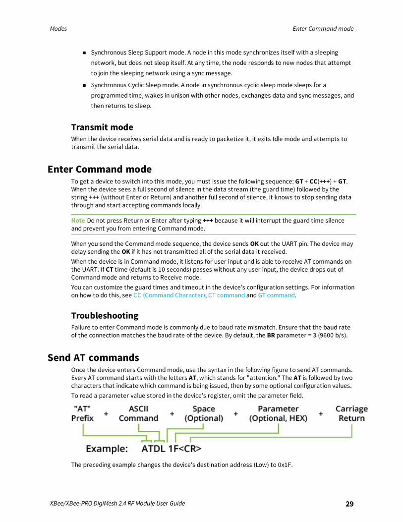
Send AT commandsOnce the device enters Commandmode, use the syntax in the following figure to send AT commands.Every AT command starts with the letters AT, which stands for "attention." The AT is followed by twocharacters that indicate which command is being issued, then by some optional configuration values.To read a parameter value stored in the device’s register, omit the parameter field.
The preceding example changes the device's destination address (Low) to 0x1F.
Modes Exit Command mode
XBee/XBee-PRO DigiMesh 2.4 RF Module User Guide 30
Multiple AT commandsYou can sendmultiple AT commands at a time when they are separated by a comma in Commandmode; for example, ATSH,SL.
Parameter formatRefer to the list of AT commands for the format of individual AT command parameters. Valid formatsfor hexidecimal values include with or without a leading 0x for example FFFF or 0xFFFF.
Response to AT commandsWhen reading parameters, the device returns the current parameter value instead of anOKmessage.
Exit Command mode1. Send the CN (Exit Command Mode) command followed by a carriage return.
or:
2. If the device does not receive any valid AT commands within the time specified by CT(Command Mode Timeout), it returns to Transparent or API mode. The default Command ModeTimeout is 10 seconds.
For an example of programming the device using AT Commands and descriptions of each configurableparameter, see AT commands.
Configure the XBee/XBee-PRO DigiMesh 2.4
Software libraries 32Configure the device using XCTU 32
XBee/XBee-PRO DigiMesh 2.4 RF Module User Guide 31
Configure the XBee/XBee-PRO DigiMesh 2.4 Software libraries
XBee/XBee-PRO DigiMesh 2.4 RF Module User Guide 32
Software librariesOne way to communicate with the XBee/XBee-PRO DigiMesh 2.4 is by using a software library. Thelibraries available for use with the XBee/XBee-PRO DigiMesh 2.4 include:
n XBee Java library
n XBee Python library
n XBee ANSI C library
The XBee Java Library is a Java API. The package includes the XBee library, its source code and acollection of samples that help you develop Java applications to communicate with your XBee devices.The XBee Python Library is a Python API that dramatically reduces the time to market of XBeeprojects developed in Python and facilitates the development of these types of applications, making itan easy process.The XBee ANSI C Library project is a collection of portable ANSI C code for communicating with thedevices in API mode.
Configure the device using XCTUXBee Configuration and Test Utility (XCTU) is a multi-platform program that enables users to interactwith Digi radio frequency (RF) devices through a graphical interface. The application includes built-intools that make it easy to set up, configure, and test Digi RF devices.For instructions on downloading and using XCTU, see the XCTU User Guide.
Serial communication
Serial interface 34UART data flow 34Serial buffers 35Serial flow control 36
XBee/XBee-PRO DigiMesh 2.4 RF Module User Guide 33
Serial communication Serial interface
XBee/XBee-PRO DigiMesh 2.4 RF Module User Guide 34
Serial interfaceThe XBee/XBee-PRO DigiMesh 2.4 provides a serial interface to an RF link. The XBee/XBee-PRODigiMesh 2.4 converts serial data to RF data and sends that data to any device in an RF network. Thedevice can communicate through its serial port with any logic and voltage compatible universalasynchronous receiver/transmitter (UART) or through a level translator to any serial device.
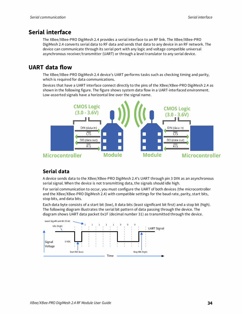
UART data flowThe XBee/XBee-PRO DigiMesh 2.4 device’s UART performs tasks such as checking timing and parity,which is required for data communications.Devices that have a UART interface connect directly to the pins of the XBee/XBee-PRO DigiMesh 2.4 asshown in the following figure. The figure shows system data flow in a UART-interfaced environment.Low-asserted signals have a horizontal line over the signal name.
Serial dataA device sends data to the XBee/XBee-PRO DigiMesh 2.4's UART through pin 3 DIN as an asynchronousserial signal. When the device is not transmitting data, the signals should idle high.For serial communication to occur, you must configure the UART of both devices (the microcontrollerand the XBee/XBee-PRO DigiMesh 2.4) with compatible settings for the baud rate, parity, start bits,stop bits, and data bits.Each data byte consists of a start bit (low), 8 data bits (least significant bit first) and a stop bit (high).The following diagram illustrates the serial bit pattern of data passing through the device. Thediagram shows UART data packet 0x1F (decimal number 31) as transmitted through the device.
Serial communication Serial buffers
XBee/XBee-PRO DigiMesh 2.4 RF Module User Guide 35
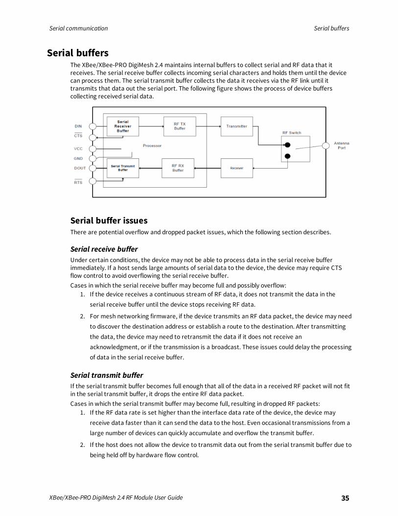
Serial buffersThe XBee/XBee-PRO DigiMesh 2.4 maintains internal buffers to collect serial and RF data that itreceives. The serial receive buffer collects incoming serial characters and holds them until the devicecan process them. The serial transmit buffer collects the data it receives via the RF link until ittransmits that data out the serial port. The following figure shows the process of device bufferscollecting received serial data.
Serial buffer issuesThere are potential overflow and dropped packet issues, which the following section describes.
Serial receive bufferUnder certain conditions, the device may not be able to process data in the serial receive bufferimmediately. If a host sends large amounts of serial data to the device, the device may require CTSflow control to avoid overflowing the serial receive buffer.Cases in which the serial receive buffer may become full and possibly overflow:
1. If the device receives a continuous stream of RF data, it does not transmit the data in theserial receive buffer until the device stops receiving RF data.
2. For mesh networking firmware, if the device transmits an RF data packet, the device may needto discover the destination address or establish a route to the destination. After transmittingthe data, the device may need to retransmit the data if it does not receive anacknowledgment, or if the transmission is a broadcast. These issues could delay the processingof data in the serial receive buffer.
Serial transmit bufferIf the serial transmit buffer becomes full enough that all of the data in a received RF packet will not fitin the serial transmit buffer, it drops the entire RF data packet.Cases in which the serial transmit buffer may become full, resulting in dropped RF packets:
1. If the RF data rate is set higher than the interface data rate of the device, the device mayreceive data faster than it can send the data to the host. Even occasional transmissions from alarge number of devices can quickly accumulate and overflow the transmit buffer.
2. If the host does not allow the device to transmit data out from the serial transmit buffer due tobeing held off by hardware flow control.
Serial communication Serial flow control
XBee/XBee-PRO DigiMesh 2.4 RF Module User Guide 36
Serial flow controlThe RTS and CTS device pins provide RTS and/or CTS flow control. CTS flow control signals the host tostop sending serial data to the device. RTS flow control lets the host signal the device so it will notsend the data in the serial transmit buffer out the UART. Use the D6 and D7 commands to enable RTSand CTS flow control.
CTS flow controlCTS flow control is enabled by default; you can disable it with the D7 command. When the serialreceive buffer fills with the number of bytes specified by the FT parameter, the device de-asserts CTS(sets it high) to signal the host device to stop sending serial data. The device re-asserts CTS when lessthan FT-16 bytes are in the UART receive buffer; for more information, see FT (Flow ControlThreshold).
RTS flow controlIf you send the D6 command to enable RTS flow control, the device does not send data in the serialtransmit buffer out the DOUT pin as long as RTS is de-asserted (set high). Do not de-assert RTS forlong periods of time or the serial transmit buffer will fill. If the device receives an RF data packet andthe serial transmit buffer does not have enough space for all of the data bytes, it discards the entireRF data packet.

Work with networked devices
Network commissioning and diagnostics 38Establish andmaintain network links 39Test links in a network - loopback cluster 40Test links between adjacent devices 41Monitor I/O lines 48
XBee/XBee-PRO DigiMesh 2.4 RF Module User Guide 37
Work with networked devices Network commissioning and diagnostics
XBee/XBee-PRO DigiMesh 2.4 RF Module User Guide 38
Network commissioning and diagnosticsWe call the process of discovering and configuring devices in a network for operation, "networkcommissioning." Devices include several device discovery and configuration features. In addition toconfiguring devices, you must develop a strategy to place devices to ensure reliable routes. Toaccommodate these requirements, modules include features to aid in placing devices, configuringdevices, and network diagnostics.
Local configurationYou can configure devices locally using serial commands in Transparent or API mode, or remotelyusing remote API commands. Devices that are in API mode can send configuration commands to setor read the configuration settings of any device in the network.
Remote configurationWhen you do not have access to the device's serial port, you can use a separate device in API mode toremotely configure it. To remotely configure devices, use the following steps.
Send a remote commandTo send a remote command, populate the Remote AT Command Request frame - 0x17 with:
1. The 64-bit address of the remote device.
2. The correct command options value.
3. Optionally, the command and parameter data.
4. If you want a command response, set the Frame ID field to a non-zero value.
The firmware only supports unicasts of remote commands. You cannot broadcast remote commands.XCTU has a Frames Generator tool that can assist you with building and sending a remote AT frame;see Frames generator tool in the XCTU User Guide.
Apply changes on remote devicesWhen you use remote commands to change the command parameter settings on a remote device,you must apply the parameter changes or they do not take effect. For example, if you change the BDparameter, the actual serial interface rate does not change on the remote device until you apply thechanges. You can apply the changes using remote commands in one of three ways:
1. Set the apply changes option bit in the API frame.
2. Send an AC command to the remote device.
3. Send the WR command followed by the FR command to the remote device to save the changesand reset the device.
Remote command response
If a local device sends a command request to a remote device, and the API frame ID is non-zero, theremote device sends a remote command response transmission back to the local device.
When the local device receives a remote command response transmission, it sends a remotecommand response API frame out its UART. The remote command response indicates:
1. The status of the command, which is either success or the reason for failure.
2. In the case of a command query, it includes the register value.
Work with networked devices Establish and maintain network links
XBee/XBee-PRO DigiMesh 2.4 RF Module User Guide 39
The device that sends a remote command does not receive a remote command response frame if:1. It could not reach the destination device.
2. You set the frame ID to 0 in the remote command request.
Establish and maintain network links
Build aggregate routesIn many applications, many or all of the nodes in the network must transmit data to a centralaggregator node. In a new DigiMesh network, the overhead of these nodes discovering routes to theaggregator node can be extensive and taxing on the network. To eliminate this overhead, you can usethe AG command to automatically build routes to an aggregate node in a DigiMesh network.To send a unicast, devices configured for Transparent mode (AP = 0) must set their DH/DL registers tothe MAC address of the node that they need to transmit to. In networks of Transparent mode devicesthat transmit to an aggregator node it is necessary to set every device's DH/DL registers to the MACaddress of the aggregator node. This can be a tedious process. A simple and effective method is to usethe AG command to set the DH/DL registers of all the nodes in a DigiMesh network to that of theaggregator node.Upon deploying a DigiMesh network, you can issue the AG command on the desired aggregator nodeto cause all nodes in the network to build routes to the aggregator node. You can optionally use theAG command to automatically update the DH/DL registers to match the MAC address of theaggregator node.The AG command requires a 64-bit parameter. The parameter indicates the current value of theDH/DL registers on a device; typically you should replace this value with the 64-bit address of the nodesending the AG broadcast. However, if you do not want to update the DH/DL of the device receivingthe AG broadcast you can use the invalid address of 0xFFFE. The receiving nodes that are configuredin API mode output an Aggregator Update API frame (0x8E) if they update their DH/DL address; for adescription of the frame, see Aggregate Addressing Update frame - 0x8E.All devices that receive an AG broadcast update their routing table information to build a route to thesending device, regardless of whether or not their DH/DL address is updated. The devices use thisrouting information for future DigiMesh unicast transmissions.
DigiMesh routing examples
Example one:In a scenario where you deploy a network, and then you want to update the DH and DL registers of allthe devices in the network so that they use the MAC address of the aggregator node, which has theMAC address 0x0013A200 4052C507, you could use the following technique.
1. Deploy all devices in the network with the default DH/DL of 0xFFFF.
2. Serially, send an ATAGFFFF command to the aggregator node so it sends the broadcasttransmission to the rest of the nodes.
All the nodes in the network that receive the AG broadcast set their DH to 0x0013A200 and their DL to0x4052C507. These nodes automatically build a route to the aggregator node.
Example two:If you want all of the nodes in the network to build routes to an aggregator node with a MAC addressof 0x0013A200 4052C507 without affecting the DH and DL registers of any nodes in the network:
Work with networked devices Test links in a network - loopback cluster
XBee/XBee-PRO DigiMesh 2.4 RF Module User Guide 40
1. Send the ATAGFFFE command to the aggregator node. This sends an AG broadcast to all of thenodes in the network.
2. All of the nodes internally update only their routing table information to contain a route to theaggregator node.
3. None of the nodes update their DH and DL registers because none of the registers are set tothe 0xFFFE address.
Replace nodesYou can use the AG command to update the routing table and DH/DL registers in the network afteryou replace a device. To update only the routing table information without affecting the DH and DLregisters, use the process in example two, above.To update the DH and DL registers of the network, use example three, below.
Example three:This example shows how to cause all devices to update their DH and DL registers to the MAC addressof the sending device. In this case, assume you are using a device with a serial number of 0x0013A2004052C507 as a network aggregator, and the sending device has a MAC address of 0x0013A200F5E4D3B2 To update the DH and DL registers to the sending device's MAC address:
1. Replace the aggregator with 0x0013A200 F5E4D3B2.
2. Send the ATAG0013A200 4052C507 command to the new device.
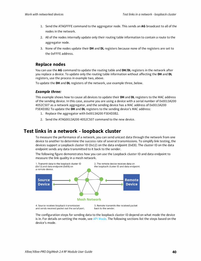
Test links in a network - loopback clusterTo measure the performance of a network, you can send unicast data through the network from onedevice to another to determine the success rate of several transmissions. To simplify link testing, thedevices support a Loopback cluster ID (0x12) on the data endpoint (0xE8). The cluster ID on the dataendpoint sends any data transmitted to it back to the sender.The following figure demonstrates how you can use the Loopback cluster ID and data endpoint tomeasure the link quality in a mesh network.
The configuration steps for sending data to the loopback cluster ID depend on what mode the deviceis in. For details on setting the mode, see API Mode. The following sections list the steps based on thedevice's mode.
Work with networked devices Test links between adjacent devices
XBee/XBee-PRO DigiMesh 2.4 RF Module User Guide 41
Transparent operating mode configuration (AP = 0)To send data to the loopback cluster ID on the data endpoint of a remote device:
1. Set the CI command to 0x12.
2. Set the DH and DL commands to the address of the remote device.
After exiting Commandmode, the device transmits any serial characters it received to the remotedevice, which returns those characters to the sending device.
API operating mode configuration (AP = 1 or AP = 2)Send an Explicit Addressing Command frame - 0x11 using 0x12 as the cluster ID and 0xE8 as both thesource and destination endpoint.The remote device echoes back the data packets it receives to the sending device.
Test links between adjacent devicesIt often helps to test the quality of a link between two adjacent modules in a network. You can use theTest Link Request Cluster ID to send a number of test packets between any two devices in a network.To clarify the example, we refer to "device A" and "device B" in this section.To request that device B perform a link test against device A:
1. Use device A in API mode (AP = 1) to send an Explicit Addressing Command (0x11) frame todevice B.
2. Address the frame to the Test Link Request Cluster ID (0x0014) and destination endpoint: 0xE6.
3. Include a 12-byte payload in the Explicit Addressing Command frame with the following format:
Number ofbytes Field name Description
8 Destinationaddress
The address the device uses to test its link. For this example, use thedevice A address.
2 Payload size The size of the test packet. Use the NP command to query themaximum payload size for the device.
2 Iterations The number of packets to send. This must be a number between 1 and4000.
4. Device B should transmit test link packets.
5. When device B completes transmitting the test link packets, it sends the following data packetto device A's Test Link Result Cluster (0x0094) on endpoint (0xE6).
6. Device A outputs the following information as an API Explicit RX Indicator (0x91) frame:
Number ofbytes Field name Description
8 Destinationaddress
The address the device used to test its link.
Work with networked devices Test links between adjacent devices
XBee/XBee-PRO DigiMesh 2.4 RF Module User Guide 42
Number ofbytes Field name Description
2 Payload size The size of the test packet device A sent to test the link.
2 Iterations The number of packets that device A sent.
2 Success The number of packets that were successfullyacknowledged.
2 Retries The number of MAC retries used to transfer all the packets.
1 Result 0x00 - the command was successful.0x03 - invalid parameter used.
1 RR The maximum number of MAC retries allowed.
1 maxRSSI The strongest RSSI reading observed during the test.
1 minRSSI The weakest RSSI reading observed during the test.
1 avgRSSI The average RSSI reading observed during the test.
ExampleSuppose that you want to test the link between device A (SH/SL = 0x0013A200 40521234) and deviceB (SH/SL=0x0013A 200 4052ABCD) by transmitting 1000 40-byte packets:Send the following API packet to the serial interface of device A.In the following example packet, whitespace marks fields, bold text is the payload portion of thepacket:7E 0020 11 01 0013A20040521234 FFFE E6 E6 0014 C105 00 00 0013A2004052ABCD 0028 03E8 EBWhen the test is finished, the following API frame may be received:7E 0027 91 0013A20040521234 FFFE E6 E6 0094 C105 00 0013A2004052ABCD 0028 03E8 03E7 006400 0A 50 53 52 9FThis means:
n 999 out of 1000 packets were successful.
n The device made 100 retries.
n RR = 10.
n maxRSSI = -80 dBm.
n minRSSI = -83 dBm.
n avgRSSI = -82 dBm.
If the Result field does not equal zero, an error has occurred. Ignore the other fields in the packet.If the Success field equals zero, ignore the RSSI fields.The device that sends the request for initiating the Test link and outputs the result does not need tobe the sender or receiver of the test. It is possible for a third node, "device C", to request device A toperform a test link against device B and send the results back to device C to be output. It is alsopossible for device B to request device A to perform the previously mentioned test. In other words, theframes can be sent by either device A, device B or device C and in all cases the test is the same: deviceA sends data to device B and reports the results.
Work with networked devices Test links between adjacent devices
XBee/XBee-PRO DigiMesh 2.4 RF Module User Guide 43
RSSI indicatorsThe received signal strength indicator (RSSI) measures the amount of power present in a radio signal.It is an approximate value for signal strength received on an antenna.You can use the DB command to measure the RSSI on a device. DB returns the RSSI value measured in-dBm of the last packet the device received. This number can be misleading in multi-hop DigiMeshnetworks. The DB value only indicates the received signal strength of the last hop. If a transmissionspans multiple hops, the DB value provides no indication of the overall transmission path, or thequality of the worst link, it only indicates the quality of the last link.To determine the DB value in hardware:
1. Use the PO command to enable the RSSI pulse-width modulation (PWM) functionality.
2. Use the RSSI/PWM module pin (pin 6). When the device receives data, it sets the RSSI PWMduty cycle to a value based on the RSSI of the packet it receives.
This value only indicates the quality of the last hop of a multi-hop transmission. You could connect thispin to an LED to indicate if the link is stable or not.
Discover all the devices on a networkYou can use the ND (Network Discovery) command to discover all devices on a network. When yousend the ND command:
1. The device sends a broadcast ND command through the network.
2. All devices that receive the command send a response that includes their addressinginformation, node identifier string and other relevant information. For more information on thenode identifier string, see NI command.
ND is useful for generating a list of all device addresses in a network.When a device receives the network discovery command, it waits a random time before sending itsown response. You can use the NT command to set the maximum time delay on the device that youuse to send the ND command.
n The device that sends the ND includes its NT setting in the transmission to provide a delaywindow for all devices in the network.
n The default NT value is 0x82 (13 seconds).
Trace route optionIn many networks, it is useful to determine the route that a DigiMesh unicast takes to its destination;particularly, when you set up a network or want to diagnose problems within a network.
Note Because of the large number of Route Information Packet frames that a unicast with traceroute enabled can generate, we suggest you only use the trace route option for occasional diagnosticpurposes and not for normal operations.
The Transmit Request (0x10) frame contains a trace route option, which transmits routinginformation packets to the originator of the unicast using the intermediate nodes.When a device sends a unicast with the trace route option enabled, the unicast transmits to itsdestination devices, which forward the unicast to its eventual destination. The destination devicetransmits a Route Information Packet (0x8D) frame back along the route to the unicast originator.The Route Information Packet frame contains:
Work with networked devices Test links between adjacent devices
XBee/XBee-PRO DigiMesh 2.4 RF Module User Guide 44
n Addressing information for the unicast.
n Addressing information for the intermediate hop.
n Other link quality information.
For a full description of the Route Information Packet frame, see Route Information Packet frame -0x8D.
Trace route exampleSuppose that you successfully unicast a data packet with trace route enabled from device A to deviceE, through devices B, C, and D. The following sequence would occur:
n After the data packet makes a successful MAC transmission from device A to device B, device Aoutputs a Route Information Packet frame indicating that the transmission of the data packetfrom device A to device E was successful in forwarding one hop from device A to device B.
n After the data packet makes a successful MAC transmission from device B to device C, device Btransmits a Route Information Packet frame to device A. When device A receives the RouteInformation packet, it outputs it over its serial interface.
n After the data packet makes a successful MAC transmission from device C to device D, device Ctransmits a Route Information Packet frame to device A (through device B). When device Areceives the Route Information packet, it outputs it over its serial interface.
n After the data packet makes a successful MAC transmission from device D to device E, device Dtransmits a Route Information Packet frame to device A (through device C and device B). Whendevice A receives the Route Information packet, it outputs it over its serial interface.
There is no guarantee that Route Information Packet frames will arrive in the same order as theroute taken by the unicast packet. On a weak route, it is also possible for the transmission of RouteInformation Packet frames to fail before arriving at the unicast originator.
Discover devices within RF rangen You can use the FN (Find Neighbors) command to discover the devices that are immediate
neighbors (within RF range) of a particular device.
n FN is useful in determining network topology and determining possible routes.
You can send FN locally on a device in Commandmode or you can use a local AT Command frame -0x08.To use FN remotely, send the target node a Remote AT Command Request frame - 0x17 using FN asthe name of the AT command.The device you use to send FN transmits a zero-hop broadcast to all of its immediate neighbors. All ofthe devices that receive this broadcast send an RF packet to the device that transmitted the FNcommand. If you sent FN remotely, the target devices respond directly to the device that sent the FNcommand. The device that sends FN outputs a response packet in the same format as an ATCommand Response frame - 0x88.
NACK messagesTransmit Request (0x10 and 0x11) frames contain a negative-acknowledge character (NACK) APIoption (Bit 2 of the Transmit Options field).
Work with networked devices Test links between adjacent devices
XBee/XBee-PRO DigiMesh 2.4 RF Module User Guide 45
If you use this option when transmitting data, when a MAC acknowledgment failure occurs on one ofthe hops to the destination device, the device generates a Route Information Packet (0x8D) frameand sends it to the originator of the unicast.This information is useful because it allows you to identify and repair marginal links.
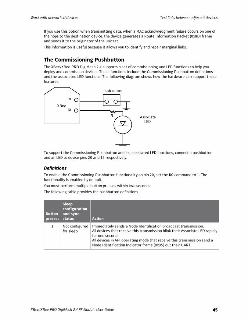
The Commissioning PushbuttonThe XBee/XBee-PRO DigiMesh 2.4 supports a set of commissioning and LED functions to help youdeploy and commission devices. These functions include the Commissioning Pushbutton definitionsand the associated LED functions. The following diagram shows how the hardware can support thesefeatures.
To support the Commissioning Pushbutton and its associated LED functions, connect a pushbuttonand an LED to device pins 20 and 15 respectively.
DefinitionsTo enable the Commissioning Pushbutton functionality on pin 20, set the D0 command to 1. Thefunctionality is enabled by default.You must perform multiple button presses within two seconds.The following table provides the pushbutton definitions.
Buttonpresses
Sleepconfigurationand syncstatus Action
1 Not configuredfor sleep
Immediately sends a Node Identification broadcast transmission.All devices that receive this transmission blink their Associate LED rapidlyfor one second.All devices in API operating mode that receive this transmission send aNode Identification Indicator frame (0x95) out their UART.
Work with networked devices Test links between adjacent devices
XBee/XBee-PRO DigiMesh 2.4 RF Module User Guide 46
Buttonpresses
Sleepconfigurationand syncstatus Action
1 Configured forasynchronoussleep
Wakes the device for 30 seconds.Immediately sends a Node Identification broadcast transmission.All devices that receive this transmission blink their Associate LED rapidlyfor one second.All devices in API operating mode that receive this transmission send aNode Identification Indicator frame (0x95) out their UART.
1 Configured forsynchronoussleep
Wakes the module for 30 seconds or until the synchronized networkgoes to sleep.Queues a Node Identification broadcast transmission that it sends at thebeginning of the next network wake cycle.All devices that receive this transmission blink their Associate LED rapidlyfor one second.All devices in API operating mode that receive this transmission send aNode Identification Indicator frame (0x95) out their UART.
2 Not configuredforsynchronoussleep
No effect.
2 Configured forsynchronoussleep
Causes a node configured with sleeping router nomination enabled toimmediately nominate itself as the network sleep coordinator. For moreinformation, see SO command.
4 Any Sends an RE command to restore device parameters to default values.
Use the Commissioning PushbuttonUse the CB command to simulate button presses in software. Send CB with a parameter set to thenumber of button presses to perform. For example, if you send ATCB1, the device performs the action(s) associated with a single button press.Node Identification Indicator frame - 0x95 is similar to Remote Command Response frame - 0x97 – itcontains the device’s address, node identifier string (NI command), and other relevant data. Alldevices in API operating mode that receive the Node Identification Indicator frame send it out theirUART as a Node Identification Indicator frame.If you enable the Commissioning Pushbutton during sleep, it increases the sleeping current draw,especially in Asynchronous pin sleep (SM = 1) mode. When asleep, hold down the CommissioningPushbutton for up to two seconds to wake the device from sleep, then issue the two or four buttonpresses.
Associate LEDThe Associate pin (pin 15) provides an indication of the device's sleep status and diagnosticinformation. To take advantage of these indications, connect an LED to the Associate pin.To enable the Associate LED functionality, set the D5 command to 1; it is enabled by default. Ifenabled, the Associate pin is configured as an output. This section describes the behavior of the pin.The Associate pin indicates the synchronization status of a sleep compatible XBee/XBee-PRODigiMesh 2.4. If a device is not sleep compatible, the pin functions as a power indicator.
Work with networked devices Test links between adjacent devices
XBee/XBee-PRO DigiMesh 2.4 RF Module User Guide 47
Use the LT command to override the blink rate of the Associate pin. If you set LT to 0, the device usesthe default blink time: 500 ms for a sleep coordinator, 250 ms otherwise.The following table describes the Associate LED functionality.
Sleepmode LED status Meaning
0 On, blinking The device has power and is operating properly
1, 4, 5 Off The device is in a low power mode
1, 4, 5 On, blinking The device has power, is awake and is operating properly
7 On, solid The network is asleep, or the device has not synchronized with thenetwork, or has lost synchronization with the network
7, 8 On, slow blinking(500 ms blink time)
The device is acting as the network sleep coordinator and isoperating properly
7, 8 On, fast blinking(250 ms blink time)
The device is properly synchronized with the network
8 Off The device is in a low power mode
8 On, solid The device has not synchronized or has lost synchronization with thenetwork
Diagnostics supportThe Associate pin works with the Commissioning Pushbutton to provide additional diagnosticbehaviors to aid in deploying and testing a network. If you press the Commissioning Pushbutton once,the device transmits a broadcast Node Identification Indicator (0x95) frame at the beginning of thenext wake cycle if the device is sleep compatible, or immediately if the device is not sleep compatible.If you enable the Associate LED functionality using the D5 command, a device that receives thistransmission blinks its Associate pin rapidly for one second.
Work with networked devices Monitor I/O lines
XBee/XBee-PRO DigiMesh 2.4 RF Module User Guide 48
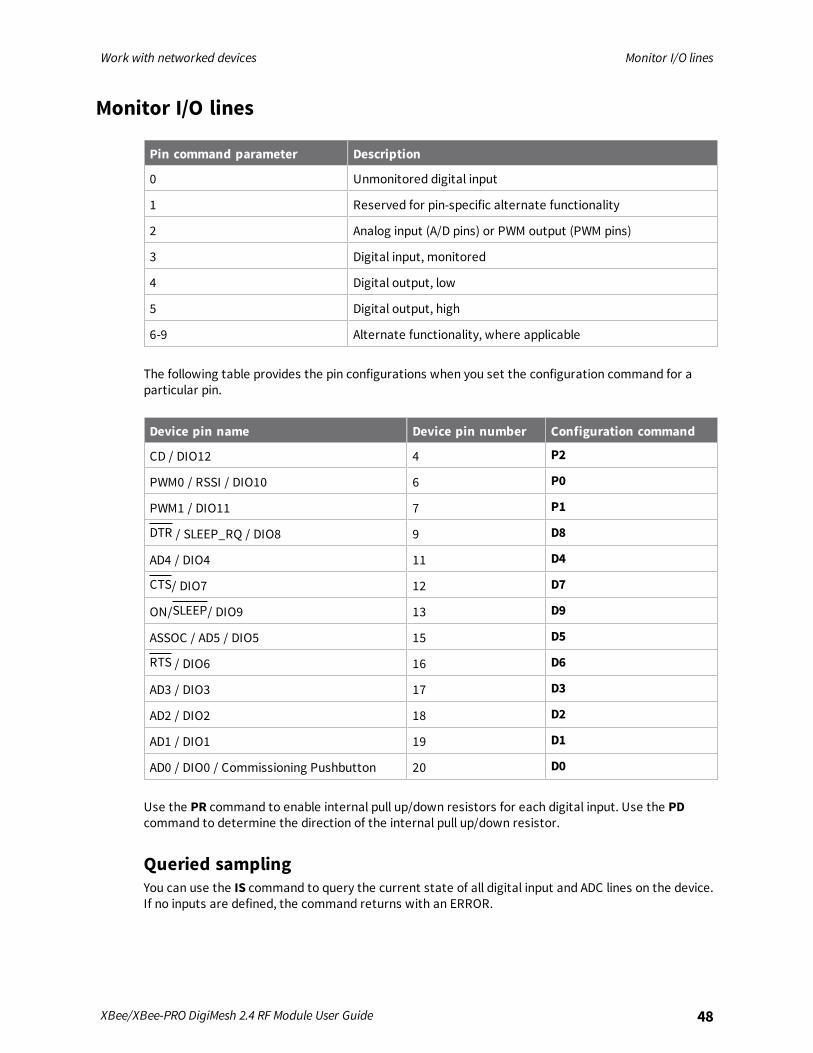
Monitor I/O lines
Pin command parameter Description
0 Unmonitored digital input
1 Reserved for pin-specific alternate functionality
2 Analog input (A/D pins) or PWM output (PWM pins)
3 Digital input, monitored
4 Digital output, low
5 Digital output, high
6-9 Alternate functionality, where applicable
The following table provides the pin configurations when you set the configuration command for aparticular pin.
Device pin name Device pin number Configuration command
CD / DIO12 4 P2
PWM0 / RSSI / DIO10 6 P0
PWM1 / DIO11 7 P1
DTR / SLEEP_RQ / DIO8 9 D8
AD4 / DIO4 11 D4
CTS/ DIO7 12 D7
ON/SLEEP/ DIO9 13 D9
ASSOC / AD5 / DIO5 15 D5
RTS / DIO6 16 D6
AD3 / DIO3 17 D3
AD2 / DIO2 18 D2
AD1 / DIO1 19 D1
AD0 / DIO0 / Commissioning Pushbutton 20 D0
Use the PR command to enable internal pull up/down resistors for each digital input. Use the PDcommand to determine the direction of the internal pull up/down resistor.
Queried samplingYou can use the IS command to query the current state of all digital input and ADC lines on the device.If no inputs are defined, the command returns with an ERROR.
Work with networked devices Monitor I/O lines
XBee/XBee-PRO DigiMesh 2.4 RF Module User Guide 49
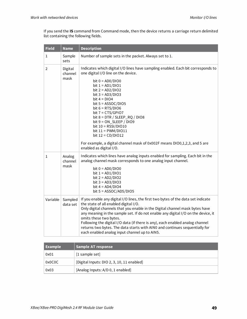
If you send the IS command from Commandmode, then the device returns a carriage return delimitedlist containing the following fields.
Field Name Description
1 Samplesets
Number of sample sets in the packet. Always set to 1.
2 Digitalchannelmask
Indicates which digital I/O lines have sampling enabled. Each bit corresponds toone digital I/O line on the device.
bit 0 = AD0/DIO0bit 1 = AD1/DIO1bit 2 = AD2/DIO2bit 3 = AD3/DIO3bit 4 = DIO4bit 5 = ASSOC/DIO5bit 6 = RTS/DIO6bit 7 = CTS/GPIO7bit 8 = DTR / SLEEP_RQ / DIO8bit 9 = ON_SLEEP / DIO9bit 10 = RSSI/DIO10bit 11 = PWM/DIO11bit 12 = CD/DIO12
For example, a digital channel mask of 0x002F means DIO0,1,2,3, and 5 areenabled as digital I/O.
1 Analogchannelmask
Indicates which lines have analog inputs enabled for sampling. Each bit in theanalog channel mask corresponds to one analog input channel.
bit 0 = AD0/DIO0bit 1 = AD1/DIO1bit 2 = AD2/DIO2bit 3 = AD3/DIO3bit 4 = AD4/DIO4bit 5 = ASSOC/AD5/DIO5
Variable Sampleddata set
If you enable any digital I/O lines, the first two bytes of the data set indicatethe state of all enabled digital I/O.Only digital channels that you enable in the Digital channel mask bytes haveany meaning in the sample set. If do not enable any digital I/O on the device, itomits these two bytes.Following the digital I/O data (if there is any), each enabled analog channelreturns two bytes. The data starts with AIN0 and continues sequentially foreach enabled analog input channel up to AIN5.
Example Sample AT response
0x01 [1 sample set]
0x0C0C [Digital Inputs: DIO 2, 3, 10, 11 enabled]
0x03 [Analog Inputs: A/D 0, 1 enabled]
Work with networked devices Monitor I/O lines
XBee/XBee-PRO DigiMesh 2.4 RF Module User Guide 50
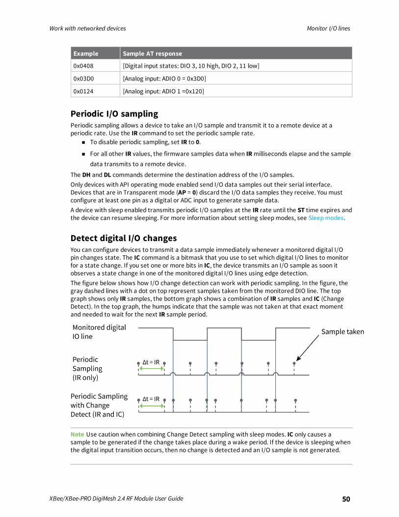
Example Sample AT response
0x0408 [Digital input states: DIO 3, 10 high, DIO 2, 11 low]
0x03D0 [Analog input: ADIO 0 = 0x3D0]
0x0124 [Analog input: ADIO 1 =0x120]
Periodic I/O samplingPeriodic sampling allows a device to take an I/O sample and transmit it to a remote device at aperiodic rate. Use the IR command to set the periodic sample rate.
n To disable periodic sampling, set IR to 0.
n For all other IR values, the firmware samples data when IRmilliseconds elapse and the sampledata transmits to a remote device.
The DH and DL commands determine the destination address of the I/O samples.Only devices with API operating mode enabled send I/O data samples out their serial interface.Devices that are in Transparent mode (AP = 0) discard the I/O data samples they receive. You mustconfigure at least one pin as a digital or ADC input to generate sample data.A device with sleep enabled transmits periodic I/O samples at the IR rate until the ST time expires andthe device can resume sleeping. For more information about setting sleepmodes, see Sleepmodes.
Detect digital I/O changesYou can configure devices to transmit a data sample immediately whenever a monitored digital I/Opin changes state. The IC command is a bitmask that you use to set which digital I/O lines to monitorfor a state change. If you set one or more bits in IC, the device transmits an I/O sample as soon itobserves a state change in one of the monitored digital I/O lines using edge detection.The figure below shows how I/O change detection can work with periodic sampling. In the figure, thegray dashed lines with a dot on top represent samples taken from the monitored DIO line. The topgraph shows only IR samples, the bottom graph shows a combination of IR samples and IC (ChangeDetect). In the top graph, the humps indicate that the sample was not taken at that exact momentand needed to wait for the next IR sample period.
Note Use caution when combining Change Detect sampling with sleepmodes. IC only causes asample to be generated if the change takes place during a wake period. If the device is sleeping whenthe digital input transition occurs, then no change is detected and an I/O sample is not generated.

Work with networked devices Monitor I/O lines
XBee/XBee-PRO DigiMesh 2.4 RF Module User Guide 51
Use IR in conjunction with IC in this instance, since IR generates an I/O sample upon wakeup andensures that the change is properly observed.
Network configurations
DigiMesh networking 53Network identifiers 54Routing 55
XBee/XBee-PRO DigiMesh 2.4 RF Module User Guide 52
Network configurations DigiMesh networking
XBee/XBee-PRO DigiMesh 2.4 RF Module User Guide 53
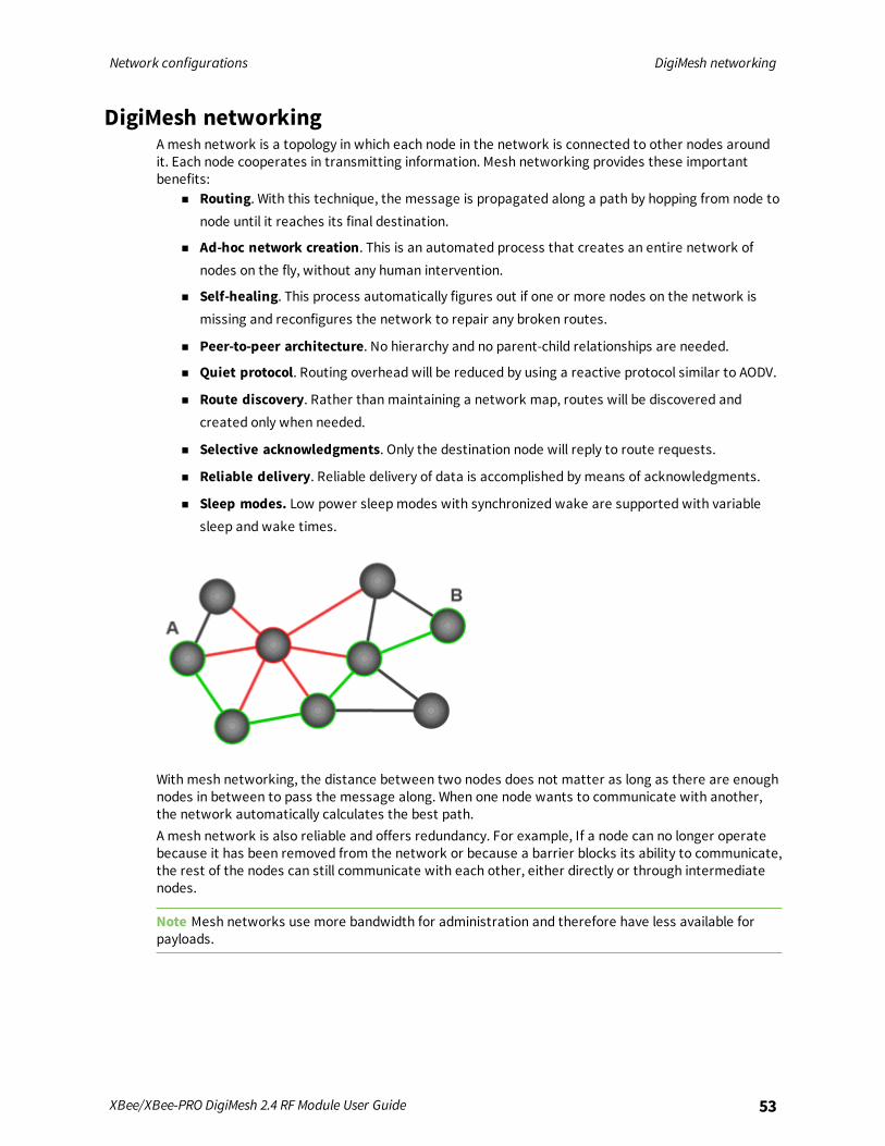
DigiMesh networkingA mesh network is a topology in which each node in the network is connected to other nodes aroundit. Each node cooperates in transmitting information. Mesh networking provides these importantbenefits:
n Routing. With this technique, the message is propagated along a path by hopping from node tonode until it reaches its final destination.
n Ad-hoc network creation. This is an automated process that creates an entire network ofnodes on the fly, without any human intervention.
n Self-healing. This process automatically figures out if one or more nodes on the network ismissing and reconfigures the network to repair any broken routes.
n Peer-to-peer architecture. No hierarchy and no parent-child relationships are needed.
n Quiet protocol. Routing overhead will be reduced by using a reactive protocol similar to AODV.
n Route discovery. Rather than maintaining a network map, routes will be discovered andcreated only when needed.
n Selective acknowledgments. Only the destination node will reply to route requests.
n Reliable delivery. Reliable delivery of data is accomplished by means of acknowledgments.
n Sleep modes. Low power sleepmodes with synchronized wake are supported with variablesleep and wake times.
With mesh networking, the distance between two nodes does not matter as long as there are enoughnodes in between to pass the message along. When one node wants to communicate with another,the network automatically calculates the best path.A mesh network is also reliable and offers redundancy. For example, If a node can no longer operatebecause it has been removed from the network or because a barrier blocks its ability to communicate,the rest of the nodes can still communicate with each other, either directly or through intermediatenodes.
Note Mesh networks use more bandwidth for administration and therefore have less available forpayloads.

Network configurations Network identifiers
XBee/XBee-PRO DigiMesh 2.4 RF Module User Guide 54
Routers and end devicesYou can use the CE command to configure devices in a DigiMesh network to act as routers or enddevices. All devices in a DigiMesh network act as routers by default. Any devices that you configure asrouters actively relay network unicast and broadcast traffic.
Network identifiersYou define DigiMesh networks with a unique network identifier. Use the ID command to set thisidentifier. For devices to communicate, you must configure them with the same network identifier andthe same operating channel. For devices to communicate, the CH and ID commands must be equal onall devices in the network.The ID command directs the devices to talk to each other by establishing that they are all part of thesame network. The ID parameter allows multiple DigiMesh networks to co-exist on the same physicalchannel.
Operating channelsThe XBee/XBee-PRO DigiMesh 2.4 operates over the 2.4 GHz band using direct sequence spreadspectrum (DSSS) modulation. DSSS modulation allows the device to operate over a channel orfrequency that you specify.The 2.4 GHz frequency band defines 16 operating channels. XBee devices support all 16 channels andXBee-PRO devices support 12 of the 16 channels.Use the CH command to select the operating channel on a device. CH tells the device the frequency touse to communicate.For devices to communicate, the CH and ID commands must be equal on all devices in the network.Note these requirements for communication:
n A device can only receive data from other devices within the same network (with the same IDvalue) and using the same channel (with the same CH value).
n A device can only transmit data to other devices within the same network (with the same IDvalue) and using the same channel (with the same CH value).
Unicast addressingWhen devices transmit using DigiMesh unicast, the network uses retries and acknowledgments(ACKs) for reliable data delivery. In a retry and acknowledgment scheme, for every data packet that adevice sends, the receiving device must send an acknowledgment back to the transmitting device tolet the sender know that the data packet arrived at the receiver. If the transmitting device does notreceive an acknowledgment then it re-sends the packet. It sends the packet a finite number of timesbefore the system times out.The MR (Mesh Network Retries) parameter determines the number of mesh network retries. Thesender device transmits RF data packets up toMR + 1 times across the network route, and thereceiver transmits ACKs when it receives the packet. If the sender does not receive a network ACKwithin the time it takes for a packet to traverse the network twice, the sender retransmits thepacket.If a device sends a unicast that uses both MAC and NWK retries and acknowledgments:
n Use MAC retries and acknowledgments for transmissions between adjacent devices in theroute.
n Use NWK retries and acknowledgments across the entire route.
Network configurations Routing
XBee/XBee-PRO DigiMesh 2.4 RF Module User Guide 55
To send unicast messages while in Transparent operating mode, set the DH and DL on thetransmitting device to match the corresponding SH and SL parameter values on the receiving device.
Broadcast addressingAll of the routers in a network receive and repeat broadcast transmissions. Broadcast transmissionsdo not use ACKs, so the sending device sends the broadcast multiple times. By default, the sendingdevice sends a broadcast transmission four times. The transmissions become automatic retrieswithout acknowledgments. This results in all nodes repeating the transmission four times as well.In order to avoid RF packet collisions, the network inserts a random delay before each router relaysthe broadcast message. You can change this random delay time with the NN parameter.Sending frequent broadcast transmissions can quickly reduce the available network bandwidth. Usebroadcast transmissions sparingly.The broadcast address is a 64 bit address with the lowest 16 bits set to 1. The upper bits are set to 0.To send a broadcast transmission:
n Set DH to 0.
n Set DL to 0xFFFF.
In API operating mode, this sets the destination address to 0x000000000000FFFF.
RoutingA device within a mesh network determines reliable routes using a routing algorithm and table. Therouting algorithm uses a reactive method derived from Ad-hoc On-demand Distance Vector (AODV).The firmware uses an associative routing table to map a destination node address with its next hop. Adevice sends a message to the next hop address, and the message either reaches its destination orforwards to an intermediate router that routes the message on to its destination.If a message has a broadcast address, it is broadcast to all neighbors, then all routers that receive themessage rebroadcast the message MT+1 times. Eventually, the message reaches the entire network.Packet tracking prevents a node from resending a broadcast message more thanMT+1 times. Thismeans that a node that relays a broadcast will only relay it after it receives it the first time and it willdiscard repeated instances of the same packet.
Route discoveryRoute discovery is a process that occurs when:
1. The source node does not have a route to the requested destination.
2. A route fails. This happens when the source node uses up its network retries without receivingan ACK.
Route discovery begins by the source node broadcasting a route request (RREQ). We call any routerthat receives the RREQ and is not the ultimate destination, an intermediate node.Intermediate nodes may either drop or forward a RREQ, depending on whether the new RREQ has abetter route back to the source node. If so, the node saves, updates and broadcasts the RREQ.When the ultimate destination receives the RREQ, it unicasts a route reply (RREP) back to the sourcenode along the path of the RREQ. It does this regardless of route quality and regardless of how manytimes it has seen an RREQ before.This allows the source node to receive multiple route replies. The source node selects the route withthe best round trip route quality, which it uses for the queued packet and for subsequent packets withthe same destination address.
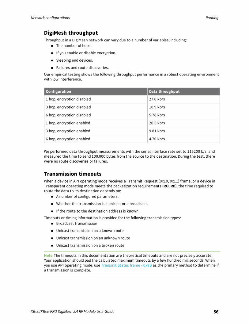
Network configurations Routing
XBee/XBee-PRO DigiMesh 2.4 RF Module User Guide 56
DigiMesh throughputThroughput in a DigiMesh network can vary due to a number of variables, including:
n The number of hops.
n If you enable or disable encryption.
n Sleeping end devices.
n Failures and route discoveries.
Our empirical testing shows the following throughput performance in a robust operating environmentwith low interference.
Configuration Data throughput
1 hop, encryption disabled 27.0 kb/s
3 hop, encryption disabled 10.9 kb/s
6 hop, encryption disabled 5.78 kb/s
1 hop, encryption enabled 20.5 kb/s
3 hop, encryption enabled 9.81 kb/s
6 hop, encryption enabled 4.70 kb/s
We performed data throughput measurements with the serial interface rate set to 115200 b/s, andmeasured the time to send 100,000 bytes from the source to the destination. During the test, therewere no route discoveries or failures.
Transmission timeoutsWhen a device in API operating mode receives a Transmit Request (0x10, 0x11) frame, or a device inTransparent operating mode meets the packetization requirements (RO, RB), the time required toroute the data to its destination depends on:
n A number of configured parameters.
n Whether the transmission is a unicast or a broadcast.
n If the route to the destination address is known.
Timeouts or timing information is provided for the following transmission types:n Broadcast transmission
n Unicast transmission on a known route
n Unicast transmission on an unknown route
n Unicast transmission on a broken route
Note The timeouts in this documentation are theoretical timeouts and are not precisely accurate.Your application should pad the calculatedmaximum timeouts by a few hundredmilliseconds. Whenyou use API operating mode, use Transmit Status frame - 0x8B as the primary method to determine ifa transmission is complete.

Network configurations Routing
XBee/XBee-PRO DigiMesh 2.4 RF Module User Guide 57
Unicast one hop time
unicastOneHopTime is a building block of many of the following calculations. It represents the amountof time it takes to send a unicast transmission between two adjacent nodes. The amount of timedepends on the RR parameter.
DigiMesh networks assume that the average number of MAC-level retries across a multi-hop wirelesslink will be three or less. The following table defines the retires and the associated time.
RR (mac retries) Unicast one hop time
0 unicastOneHopTime = 5 ms
1 unicastOneHopTime = 24 ms
2 unicastOneHopTime = 40 ms
3 unicastOneHopTime = 63 ms
Transmit a broadcastAll of the routers in a network must relay a broadcast transmission.The maximum delay occurs when the sender and receiver are on the opposite ends of the network.The NH and%H parameters define the maximum broadcast delay as follows:
BroadcastTxTime = NH * NN * %8Unless BH < NH, in which case the formula is:
BroadcastTxTime = BH * NN * %8
Transmit a unicast with a known routeWhen a device knows a route to a destination node, the transmission time is largely a function of thenumber of hops and retries. The timeout associated with a unicast assumes that the maximumnumber of hops is necessary, as specified by the NH command.You can estimate the timeout in the following manner:
knownRouteUnicastTime=2*NH*MR*unicastOneHopTime
Transmit a unicast with an unknown routeIf the transmitting device does not know the route to the destination, it begins by sending a routediscovery. If the route discovery is successful, then the transmitting device transmits data. You canestimate the timeout associated with the entire operation as follows:
unknownRouteUnicastTime=BroadcastTxTime+(NH*unicastOneHopTime)+knownRouteUnicastTime
Transmit a unicast with a broken routeIf the route to a destination node changes after route discovery completes, a node begins byattempting to send the data along the previous route. After it fails, it initiates route discovery and,when the route discovery finishes, transmits the data along the new route. You can estimate thetimeout associated with the entire operation as follows:
brokenRouteUnicastTime=BroadcastTxTime+(NH*unicastOneHopTime)+(2*knownRouteUnicastTime)

Sleep modes
About sleepmodes 59Normal mode 59Asynchronous pin sleepmode 60Asynchronous cyclic sleepmode 60Asynchronous cyclic sleep with pin wake upmode 60Synchronous sleep support mode 60Synchronous cyclic sleepmode 61The sleep timer 61Sleep coordinator sleepmodes in the DigiMesh network 61Synchronization messages 62Become a sleep coordinator 64Select sleep parameters 66Start a sleeping synchronous network 66Add a new node to an existing network 67Change sleep parameters 68Rejoin nodes that lose sync 68Diagnostics 69
XBee/XBee-PRO DigiMesh 2.4 RF Module User Guide 58
Sleep modes About sleep modes
XBee/XBee-PRO DigiMesh 2.4 RF Module User Guide 59
About sleep modesA number of low-power modes exist to enable devices to operate for extended periods of time onbattery power. Use the SM command to enable these sleepmodes. The sleepmodes arecharacterized as either:
n Asynchronous (SM = 1, 4, 5).
n Synchronous (SM = 7, 8).
In DigiMesh networks, a device functions in one of three roles:1. A sleep coordinator.
2. A potential coordinator.
3. A non-coordinator.
The difference between a potential coordinator and a non-coordinator is that a non-coordinator nodehas its SO parameter set so that it will not participate in coordinator election and cannot ever be asleep coordinator.
Asynchronous modesn Do not use asynchronous sleepmodes in a synchronous sleeping network, and vice versa.
n Use the asynchronous sleepmodes to control the sleep state on a device by device basis.
n Do not use devices operating in asynchronous sleepmode to route data.
n We strongly encourage you to set asynchronous sleeping devices as end-devices using the CEcommand. This prevents the node from attempting to route data.
Synchronous modesSynchronous sleepmakes it possible for all nodes in the network to synchronize their sleep and waketimes. All synchronized cyclic sleep nodes enter and exit a low power state at the same time.This forms a cyclic sleeping network.
n A device acting as a sleep coordinator sends a special RF packet called a sync message tosynchronize nodes.
n To make a device in the network a coordinator, a node uses several resolution criteria.
n The sleep coordinator sends one sync message at the beginning of each wake period. Thecoordinator sends the sync message as a broadcast and every node in the network repeats it.
n You can change the sleep and wake times for the entire network by locally changing thesettings on an individual device. The network uses the most recently set sleep settings.
Normal modeSet SM to 0 to enter Normal mode.Normal mode is the default sleepmode. If a device is in this mode, it does not sleep and is alwaysawake.Use mains-power for devices in Normal mode.A device in Normal mode synchronizes to a sleeping network, but does not observe synchronizationdata routing rules; it routes data at any time, regardless of the network's wake state.
Sleep modes Asynchronous pin sleep mode
XBee/XBee-PRO DigiMesh 2.4 RF Module User Guide 60
When synchronized, a device in Normal mode relays sync messages that sleep-compatible nodesgenerate, but does not generate sync messages itself.Once a device in Normal mode synchronizes with a sleeping network, you can put it into a sleep-compatible sleepmode at any time.
Asynchronous pin sleep modeSet SM to 1 to enter asynchronous pin sleepmode.Pin sleep allows the device to sleep and wake according to the state of the SLEEP_RQ pin (pin 9).When you assert SLEEP_RQ (high), the device finishes any transmit or receive operations and enters alow-power state.When you de-assert SLEEP_RQ (low), the device wakes from pin sleep.
Asynchronous cyclic sleep modeSet SM to 4 to enter asynchronous cyclic sleepmode.Cyclic sleep allows the device to sleep for a specific time and wake for a short time to poll.If the device receives serial or RF data while awake, it extends the time before it returns to sleep bythe specific amount the ST command provides. Otherwise, it enters sleepmode immediately.The ON_SLEEP line (pin 13) is asserted (high) when the device wakes, and is de-asserted (low) whenthe device sleeps.If you use the D7 command to enable hardware flow control, the CTS pin asserts (low) when thedevice wakes and can receive serial data, and de-asserts (high) when the device sleeps.
Asynchronous cyclic sleep with pin wake up modeSet SM to 5 to enter asynchronous cyclic sleep with pin wake upmode.This mode is a slight variation on asynchronous cyclic sleepmode (SM = 4) that allows you to wake adevice prematurely by asserting the SLEEP_RQ pin (pin 9).In this mode, you can wake the device after the sleep period expires, or if a high-to-low transitionoccurs on the SLEEP_RQ pin.
Synchronous sleep support modeSet SM to 7 to enter synchronous sleep support mode.A device in synchronous sleep support mode synchronizes itself with a sleeping network, but does notsleep itself. At any time, the node responds to new nodes that attempt to join the sleeping networkwith a sync message. A sleep support node only transmits normal data when the other nodes in thesleeping network are awake.Sleep support nodes are especially useful:
n When you use them as preferred sleep coordinator nodes.
n As aids in adding new nodes to a sleeping network.
Note Because sleep support nodes do not sleep, they should be mains powered.

Sleep modes Synchronous cyclic sleep mode
XBee/XBee-PRO DigiMesh 2.4 RF Module User Guide 61
Synchronous cyclic sleep modeSet SM to 8 to enter synchronous cyclic sleepmode.A device in synchronous cyclic sleepmode sleeps for a programmed time, wakes in unison with othernodes, exchanges data and sync messages, and then returns to sleep. While asleep, it cannot receiveRF messages or receive data (including commands) from the UART port.Generally, the network’s sleep coordinator specifies the sleep and wake times based on its SP and STsettings. The device only uses these parameters at startup until the device synchronizes with thenetwork.When a device has synchronized with the network, you can query its sleep and wake times with theOS andOW commands respectively.If D9 = 1 (ON_SLEEP enabled) on a cyclic sleep node, the ON_SLEEP line asserts when the device isawake and de-asserts when the device is asleep.If D7 = 1, the device de-asserts CTS while asleep.A newly-powered, unsynchronized, sleeping device polls for a synchronizedmessage and then sleepsfor the period that the SP command specifies, repeating this cycle until it synchronizes by receiving async message. Once it receives a sync message, the device synchronizes itself with the network.
Note Configure all nodes in a synchronous sleep network to operate in either synchronous sleepsupport mode or synchronous cyclic sleepmode. asynchronous sleeping nodes are not compatiblewith synchronous sleeping nodes.
The sleep timerIf the device receives serial or RF data in Asynchronous cyclic sleepmode and Asynchronous cyclicsleep with pin wake upmodes (SM = 4 or SM = 5), it starts a sleep timer (time until sleep).
n If the device receives any data serially or by RF link, the timer resets.
n Use ST (Wake Time) to set the duration of the timer.
n When the sleep timer expires the device returns to sleep.
Sleep coordinator sleep modes in the DigiMesh networkIn a synchronized sleeping network, one node acts as the sleep coordinator. During normaloperations, at the beginning of a wake cycle the sleep coordinator sends a sync message as abroadcast to all nodes in the network. This message contains synchronization information and thewake and sleep times for the current cycle. All cyclic sleep nodes that receive a sync message remainawake for the wake time and then sleep for the specified sleep period.The sleep coordinator sends one sync message at the beginning of each cycle with the current wakeand sleep times. All router nodes that receive this sync message relay the message to the rest of thenetwork. If the sleep coordinator does not hear a rebroadcast of the sync message by one of itsimmediate neighbors, then it re-sends the message one additional time.If you change the SP or ST parameters, the network does not apply the new settings until thebeginning of the next wake time. For more information, see Change sleep parameters.A sleeping router network is robust enough that an individual node can go several cycles withoutreceiving a sync message, due to RF interference, for example. As a node misses sync messages, thetime available for transmitting messages during the wake time reduces to maintain synchronizationaccuracy. By default, a device reduces its active sleep time progressively as it misses sync messages.
Sleep modes Synchronization messages
XBee/XBee-PRO DigiMesh 2.4 RF Module User Guide 62
Synchronization messagesA sleep coordinator regularly sends sync messages to keep the network in sync. Unsynchronizednodes also sendmessages requesting sync information.Sleep compatible nodes use Deployment mode when they first power up and the sync message hasnot been relayed. A sleep coordinator in Deployment mode rapidly sends sync messages until itreceives a relay of one of those messages. Deployment mode:
n Allows you to effectively deploy a network.
n Allows a sleep coordinator that resets to rapidly re-synchronize with the rest of the network.
If a node exits deployment mode and then receives a sync message from a sleep coordinator that is inDeployment mode, it rejects the sync message and sends a corrective sync to the sleep coordinator.Use the SO (sleep options) command to disable deployment mode. This option is enabled by default.A sleep coordinator that is not in deployment mode sends a sync message at the beginning of thewake cycle. The sleep coordinator listens for a neighboring node to relay the sync. If it does not hearthe relay, the sleep coordinator sends the sync one additional time.A node that is not a sleep coordinator and has never been synchronized sends a message requestingsync information at the beginning of its wake cycle. Synchronized nodes which receive one of thesemessages respond with a synchronization packet.If you use the SO command to configure nodes as non-coordinators, and if the non-coordinators go sixor more sleep cycles without hearing a sync, they send a message requesting sync at the beginning oftheir wake period.The following diagram illustrates the synchronization behavior of sleep compatible devices.
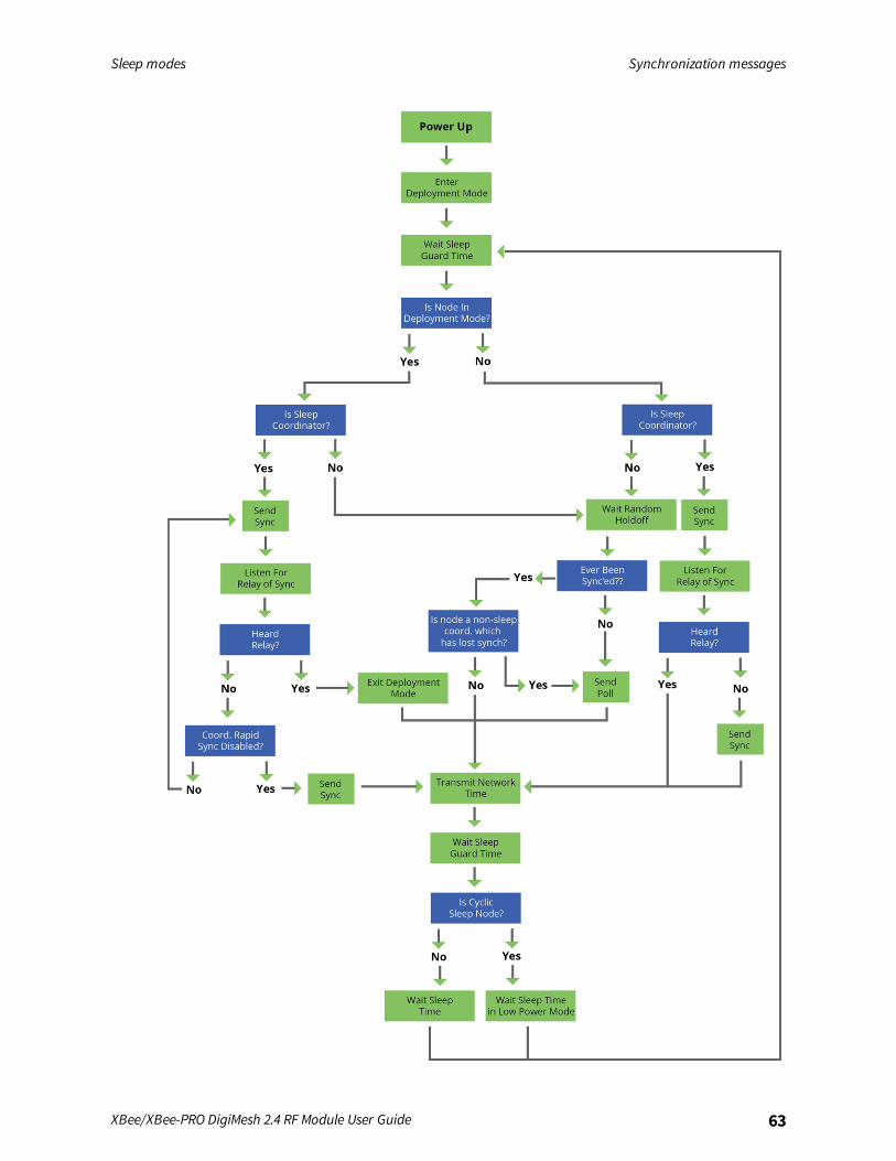
Sleep modes Synchronization messages
XBee/XBee-PRO DigiMesh 2.4 RF Module User Guide 63
Sleep modes Become a sleep coordinator
XBee/XBee-PRO DigiMesh 2.4 RF Module User Guide 64
Become a sleep coordinatorIn DigiMesh networks, a device can become a sleep coordinator in one of four ways:
n Define a preferred sleep coordinator
n A potential sleep coordinator misses three or more sync messages
n Press the Commissioning Pushbutton twice on a potential sleep coordinator
n Change the sleep timing values on a potential sleep coordinator
Preferred sleep coordinator optionYou can specify that a node always act as a sleep coordinator. To do this, set the preferred sleepcoordinator bit (bit 0) in the SO command to 1.A node with the sleep coordinator bit set always sends a sync message at the beginning of a wakecycle. To avoid network congestion and synchronization conflicts, do not set this bit on more than onenode in the network.Although it is not necessary to specify a preferred sleep coordinator, doing so improves networkperformance.A node that is centrally located in the network can serve as a good sleep coordinator, because itminimizes the number of hops a sync message takes to get across the network.A sleep support node and/or a node that is mains powered is a good candidate to be a sleepcoordinator.
CAUTION! Use the preferred sleep coordinator bit with caution. The advantages of usingthe option become weaknesses if you use it on a node that is not in the proper positionor configuration.
You can also use the preferred sleep coordinator option when you set up a network for the first time.When you start a network, you can configure a node as a sleep coordinator so it will begin sendingsleepmessages. After you set up the network, disable the preferred sleep coordinator bit.
Resolution criteria and selection optionThere is an optional selection process with resolution criteria that occurs on a node if it loses contactwith the network sleep coordinator. By default, this process is disabled. Use the SO command toenable this process. This process occurs automatically if a node loses contact with the previous sleepcoordinator.If you enable the process on any sleep compatible node, it is eligible to become the sleep coordinatorfor the network.A sleep compatible node may become a sleep coordinator if it:
n Misses three or more sync messages.
n Is not configured as a non-coordinator (presumably because the sleep coordinator has beendisabled).
Depending on the platform and other configurable options, such a node eventually uses the selectionprocess after a number of sleep cycles without a sync.A node that uses the selection process begins acting as the new network sleep coordinator.
Sleep modes Become a sleep coordinator
XBee/XBee-PRO DigiMesh 2.4 RF Module User Guide 65
It is possible for multiple nodes to declare themselves as the sleep coordinator. If this occurs, thefirmware uses the following resolution criteria to identify the sleep coordinator from among the nodesusing the selection process:
1. Newer sleep parameters: the network considers a node using newer sleep parameters (SP andST) as higher priority to a node using older sleep parameters. See Change sleep parameters.
2. Preferred sleep coordinator: a node acting as a preferred sleep coordinator is higher priority toother nodes.
3. Sleep support node: sleep support nodes are higher priority to cyclic sleep nodes. You canmodify this behavior using the SO parameter.
4. Serial number: If the previous factors do not resolve the priority, the network considers thenode with the higher serial number to be higher priority.
Commissioning Pushbutton optionUse the Commissioning Pushbutton to select a device to act as the sleep coordinator.If you enable the Commissioning Pushbutton functionality, you can immediately select a device as asleep coordinator by pressing the Commissioning Pushbutton twice or by issuing the CB2 command.The device you select in this manner is still subject to the resolution criteria process.Only sleep coordinator nodes honor Commissioning Pushbutton nomination requests. A nodeconfigured as a non-sleep coordinator ignores commissioning button nomination requests.
Change sleep parametersAny sleep compatible node in the network that does not have the non-coordinator sleep option setcan make changes to the network’s sleep and wake times. If you change a node’s SP or ST to valuesdifferent from those that the network is using, the node becomes the sleep coordinator. The nodebegins sending sync messages with the new sleep parameters at the beginning of the next wakecycle.
n For normal operations, a device uses the sleep and wake parameters it gets from the sleepsync message, not the ones specified in its SP and ST parameters. It does not update the SPand ST parameters with the values of the sync message. Use the OS andOW commands toquery the operating network sleep and wake times currently being used by the node.
n Changing network parameters can cause a node to become a sleep coordinator and changethe sleep settings of the network. The following commands can cause this to occur: NH, NN,andMR.
For most applications, we recommend configuring the NH, NN, andMR network parameters duringinitial deployment only. The default values of NH andNN are optimized to work for most deployments.
Sleep guard timesTo compensate for variations in the timekeeping hardware of the various devices in a sleeping routernetwork, the network allocates sleep guard times at the beginning and end of the wake period. Thesize of the sleep guard time varies based on the sleep and wake times you select and the number ofsleep cycles that elapse since receiving the last sync message. The sleep guard time guarantees thata destination module will be awake when the source device sends a transmission. As a node missesmore andmore consecutive sync messages, the sleep guard time increases in duration and decreasesthe available transmission time.
Sleep modes Select sleep parameters
XBee/XBee-PRO DigiMesh 2.4 RF Module User Guide 66
Auto-early wake-up sleep optionIf you have nodes that are missing sync messages and could be going out of sync with the rest of thenetwork, enabling an early wake gives the device a better chance to hear the sync messages that arebeing broadcast.Similar to the sleep guard time, the auto early wake-up option decreases the sleep period based onthe number of sync messages a node misses. This option comes at the expense of battery life.Use the SO command to disable auto-early wake-up sleep. This option is enabled by default.
Select sleep parametersChoosing proper sleep parameters is vital to creating a robust sleep-enabled network with a desirablebattery life. To select sleep parameters that will be good for most applications, follow these steps:
1. Choose NN andNH.
Based on the placement of the nodes in your network, select the appropriate values forthe NH (Network Hops) andNN (Network Delay Slots) parameters.
We optimize the default values of NH andNN to work for the majority of deployments.In most cases, we suggest that you do not modify these parameters from their defaultvalues. Decreasing these parameters for small networks can improve battery life, buttake care to not make the values too small.
2. Calculate the Sync Message Propagation Time (SMPT).
This is the maximum amount of time it takes for a sleep synchronization message topropagate to every node in the network. You can estimate this number with thefollowing formula:SMPT = NN*NH*(MT+1)*18 ms.
3. Select the duty cycle you want.
4. Choose the sleep period and wake time.
The wake time must be long enough to transmit the desired data as well as the sync message.The ST parameter automatically adjusts upwards to its minimum value when you change otherAT commands that affect it (SP, NN, andNH).Use a value larger than this minimum. If a device misses successive sync messages, it reducesits available transmit time to compensate for possible clock drift. Budget a large enough STtime to allow for the device to miss a few sync messages and still have time for normal datatransmissions.
Start a sleeping synchronous networkBy default, all new nodes operate in normal (non-sleep) mode. To start a synchronous sleepingnetwork, follow these steps:
1. Set SO to 1 to enable the preferred sleep coordinator option on one of the nodes.
2. Set its SM to a synchronous sleep compatible mode (7 or 8) with its SP and ST set to a quickcycle time. The purpose of a quick cycle time is to allow the network to send commands quicklythrough the network during commissioning.
Sleep modes Add a new node to an existing network
XBee/XBee-PRO DigiMesh 2.4 RF Module User Guide 67
3. Power on the new nodes within range of the sleep coordinator. The nodes quickly receive async message and synchronize themselves to the short cycle SP and ST set on the sleepcoordinator.
4. Configure the new nodes to the sleepmode you want, either cyclic sleeping modes or sleepsupport modes.
5. Set the SP and ST values on the sleep coordinator to the values you want for the network.
6. Wait a sleep cycle for the sleeping nodes to sync themselves to the new SP and ST values.
7. Disable the preferred sleep coordinator option bit on the sleep coordinator unless you want apreferred sleep coordinator.
8. Deploy the nodes to their positions.
Alternatively, prior to deploying the network you can use the WR command to set up nodes with theirsleep settings pre-configured and written to flash. If this is the case, you can use the CommissioningPushbutton and associate LED to aid in deployment:
1. If you are going to use a preferred sleep coordinator in the network, deploy it first.
2. If there will not be a preferred sleep coordinator, select a node for deployment, power it on andpress the Commissioning Pushbutton twice. This causes the node to begin emitting syncmessages.
3. Verify that the first node is emitting sync messages by watching its associate LED. A slow blinkindicates that the node is acting as a sleep coordinator.
4. Power on nodes in range of the sleep coordinator or other nodes that have synchronized withthe network. If the synchronized node is asleep, you can wake it by pressing theCommissioning Pushbutton once.
5. Wait a sleep cycle for the new node to sync itself.
6. Verify that the node syncs with the network. The associate LED blinks when the device isawake and synchronized.
7. Continue this process until you deploy all of the nodes.
Add a new node to an existing networkTo add a new node to the network, the node must receive a sync message from a node already in thenetwork. On power-up, an unsynchronized, sleep compatible node periodically sends a broadcastrequesting a sync message and then sleeps for its SP period. Any node in the network that receivesthis message responds with a sync. Because the network can be asleep for extended periods of time,and cannot respond to requests for sync messages, there are methods you can use to sync a newnode while the network is asleep.
1. Power the new node on within range of a sleep support node. Sleep support nodes are alwaysawake and able to respond to sync requests promptly.
2. You can wake a sleeping cyclic sleep node in the network using the Commissioning Pushbutton.Place the new node in range of the existing cyclic sleep node. Wake the existing node byholding down the Commissioning Pushbutton for two seconds, or until the node wakes. Theexisting node stays awake for 30 seconds and responds to sync requests while it is awake.
Sleep modes Change sleep parameters
XBee/XBee-PRO DigiMesh 2.4 RF Module User Guide 68
If you do not use one of these two methods, you must wait for the network to wake up before addingthe new node.Place the new node in range of the network with a sleep/wake cycle that is shorter than the wakeperiod of the network.The new node periodically sends sync requests until the network wakes up and it receives a syncmessage.
Change sleep parametersTo change the sleep and wake cycle of the network, select any sleep coordinator capable node in thenetwork and change the SP and/or ST of the node to values different than those the networkcurrently uses.
n If you use a preferred sleep coordinator or if you know which node acts as the sleepcoordinator, we suggest that you use this node to make changes to network settings.
n If you do not know the network sleep coordinator, you can use any node that does not have thenon-sleep coordinator sleep option bit set. For details on the bit, see SO command.
When you make changes to a node’s sleep parameters, that node becomes the network’s sleepcoordinator unless it has the non-sleep coordinator option selected. It sends a sync message with thenew sleep settings to the entire network at the beginning of the next wake cycle. The networkimmediately begins using the new sleep parameters after it sends this sync.Changing sleep parameters increases the chances that nodes will lose sync. If a node does not receivethe sync message with the new sleep settings, it continues to operate on its old settings. To minimizethe risk of a node losing sync and to facilitate the re-syncing of a node that does lose sync, take thefollowing precautions:
1. Whenever possible, avoid changing sleep parameters.
2. Enable the missed sync early wake up sleep option in the SO command. This option is enabledby default. This command tells a node to wake up progressively earlier based on the number ofcycles it goes without receiving a sync. This increases the probability that the un-synced nodewill be awake when the network wakes up and sends the sync message.
Note Using this sleep option increases reliability but may decrease battery life. Nodes using this sleepoption that miss sync messages increase their wake time and decrease their sleep time during cycleswhere they miss the sync message. This increases power consumption.
When you are changing between two sets of sleep settings, choose settings so that the wake periodsof the two sleep settings occur at the same time. In other words, try to satisfy the following equation:
(SP1 + ST1) = N * (SP2 + ST2)
where SP1/ST1 and SP2/ST2 are the desired sleep settings and N is an integer.
Rejoin nodes that lose syncDigiMesh networks get their robustness from routing redundancies which may be available. Werecommend architecting the network with redundant mesh nodes to increase robustness.If a scenario exists where the only route connecting a subnet to the rest of the network depends on asingle node, and that node fails or the wireless link fails due to changing environmental conditions (acatastrophic failure condition), then multiple subnets may arise using the same wake and sleep
Sleep modes Diagnostics
XBee/XBee-PRO DigiMesh 2.4 RF Module User Guide 69
intervals. When this occurs the first task is to repair, replace, and strengthen the weak link with newand/or redundant devices to fix the problem and prevent it from occurring in the future.When you use the default DigiMesh sleep parameters, separated subnets do not drift out of phasewith each other. Subnets can drift out of phase with each other if you configure the network in one ofthe following ways:
n If you disable the non-sleep coordinator bit in the SO command onmultiple devices in thenetwork, they are eligible for the network to nominate them as a sleep coordinator. For moredetails, see SO command.
n If the devices in the network do not use the auto early wake-up sleep option.
If a network has multiple subnets that drift out of phase with each other, get the subnets back inphase with the following steps:
1. Place a sleep support node in range of both subnets.
2. Select a node in the subnet that you want the other subnet to sync with.
3. Use this node to slightly change the sleep cycle settings of the network, for example,increment ST.
4. Wait for the subnet’s next wake cycle. During this cycle, the node you select to change thesleep cycle parameters sends the new settings to the entire subnet it is in range of, includingthe sleep support node that is in range of the other subnet.
5. Wait for the out of sync subnet to wake up and send a sync. When the sleep support nodereceives this sync, it rejects it and sends a sync to the subnet with the new sleep settings.
6. The subnets will now be in sync. You can remove the sleep support node.
7. You can also change the sleep cycle settings back to the previous settings.
If you only need to replace a few nodes, you can use this method:1. Reset the out of sync node and set its sleepmode to Synchronous Cyclic Sleepmode (SM = 8).
2. Set up a short sleep cycle.
3. Place the node in range of a sleep support node or wake a sleeping node with theCommissioning Pushbutton.
4. The out of sync node receives a sync from the node that is synchronized to the network. It thensyncs to the network sleep settings.
DiagnosticsThe following diagnostics are useful in applications that manage a sleeping router network:
Query sleep cycleUse the OS andOW commands to query the current operational sleep and wake times that a deviceuses.
Sleep statusUse the SS command to query useful information regarding the sleep status of the device. Use thiscommand to query if the node is currently acting as a network sleep coordinator.
Sleep modes Diagnostics
XBee/XBee-PRO DigiMesh 2.4 RF Module User Guide 70
Missed sync messages commandUse the MS command to query the number of cycles that elapsed since the device received a syncmessage.
Sleep status API messagesWhen you use the SO command to enable this option, a device that is in API operating mode outputsmodem status frames immediately after it wakes up and prior to going to sleep.
AT commands
Special commands 72MAC/PHY commands 73Network commands 77Addressing commands 79Diagnostic - addressing commands 82Addressing discovery/configuration commands 83Security commands 85Serial interfacing commands 85I/O settings commands 88I/O sampling commands 96Sleep commands 98Diagnostic - sleep status/timing commands 101Commandmode options 103Firmware version/information commands 104
XBee/XBee-PRO DigiMesh 2.4 RF Module User Guide 71

AT commands Special commands
XBee/XBee-PRO DigiMesh 2.4 RF Module User Guide 72
Special commandsThe following commands are special commands.
AC (Apply Changes)Immediately applies new settings without exiting Commandmode.
Parameter rangeN/A
DefaultN/A
FR (Software Reset)Resets the device. The device responds immediately with anOK and performs a reset 100 ms later.If you issue FRwhile the device is in Command Mode, the reset effectively exits Commandmode.
Parameter rangeN/A
DefaultN/A
RE commandRestore device parameters to factory defaults.
Parameter rangeN/A
DefaultN/A
WR commandWrites parameter values to non-volatile memory so that parameter modifications persist throughsubsequent resets.
Note Once you issue a WR command, do not send any additional characters to the device until afteryou receive the OK response.
Parameter rangeN/A
DefaultN/A
AT commands MAC/PHY commands
XBee/XBee-PRO DigiMesh 2.4 RF Module User Guide 73
MAC/PHY commandsThe following AT commands are MAC/PHY commands.
CH (Operating Channel)Set or read the operating channel devices used to transmit and receive data. The channel is one ofthree addressing configurations available to the device. The other configurations are the PAN ID (IDcommand) and destination addresses (DL and DH commands).In order for devices to communicate with each other, they must share the same channel number. Anetwork can use different channels to prevent devices in one network from listening to thetransmissions of another. Adjacent channel rejection is 23 dB.The command uses 802.15.4 channel numbers. Center frequency = 2405 MHz + (CH - 11 decimal) * 5MHz.
Parameter range0xB - 0x1A
Default0xC (12 decimal)
ID (Network ID)Set or read the user network identifier.Devices must have the same network identifier to communicate with each other.Devices can only communicate with other devices that have the same network identifier and channelconfigured.When receiving a packet, the device check this after the preamble ID. If you are using Originalequipment manufacturer (OEM) network IDs, 0xFFFF uses the factory value.
Parameter range0 - 0xFFFF
Default0x7FFF
MT (Broadcast Multi-Transmits)Set or read the number of additional MAC-level broadcast transmissions. All broadcast packets aretransmittedMT+1 times to ensure they are received.
Parameter range0 - 0xF
Default3
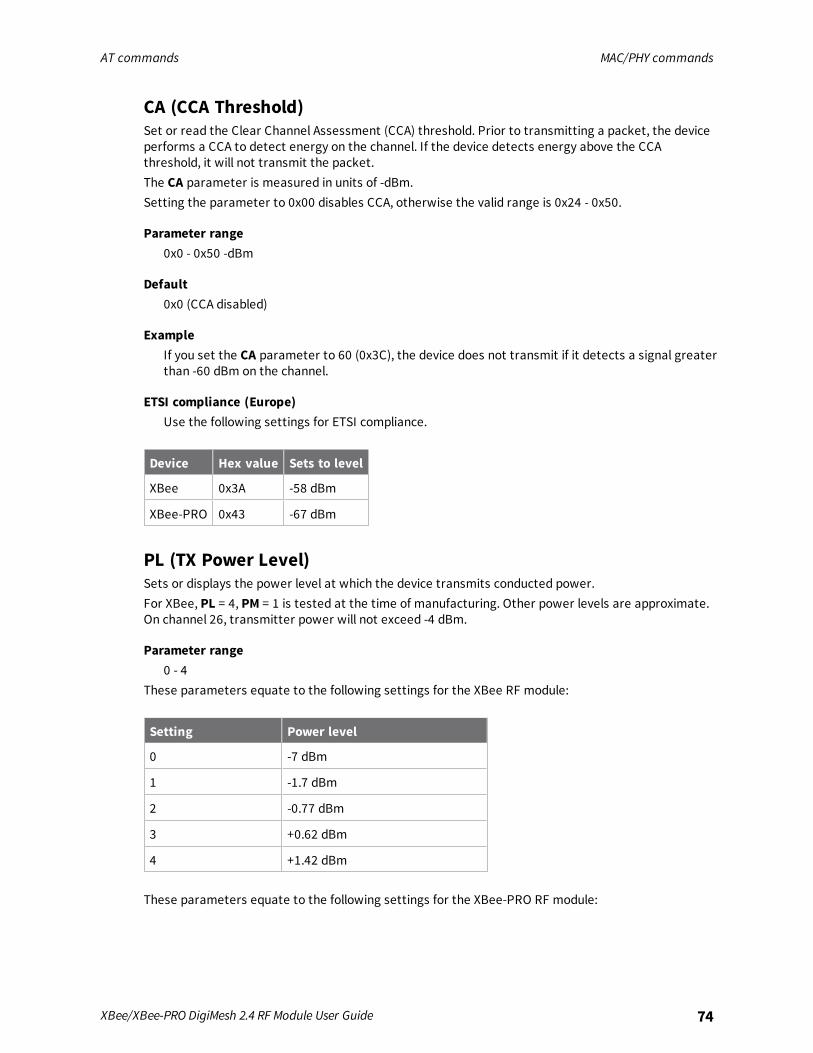
AT commands MAC/PHY commands
XBee/XBee-PRO DigiMesh 2.4 RF Module User Guide 74
CA (CCA Threshold)Set or read the Clear Channel Assessment (CCA) threshold. Prior to transmitting a packet, the deviceperforms a CCA to detect energy on the channel. If the device detects energy above the CCAthreshold, it will not transmit the packet.The CA parameter is measured in units of -dBm.Setting the parameter to 0x00 disables CCA, otherwise the valid range is 0x24 - 0x50.
Parameter range0x0 - 0x50 -dBm
Default0x0 (CCA disabled)
ExampleIf you set the CA parameter to 60 (0x3C), the device does not transmit if it detects a signal greaterthan -60 dBm on the channel.
ETSI compliance (Europe)Use the following settings for ETSI compliance.
Device Hex value Sets to level
XBee 0x3A -58 dBm
XBee-PRO 0x43 -67 dBm
PL (TX Power Level)Sets or displays the power level at which the device transmits conducted power.For XBee, PL = 4, PM = 1 is tested at the time of manufacturing. Other power levels are approximate.On channel 26, transmitter power will not exceed -4 dBm.
Parameter range0 - 4
These parameters equate to the following settings for the XBee RF module:
Setting Power level
0 -7 dBm
1 -1.7 dBm
2 -0.77 dBm
3 +0.62 dBm
4 +1.42 dBm
These parameters equate to the following settings for the XBee-PRO RF module:
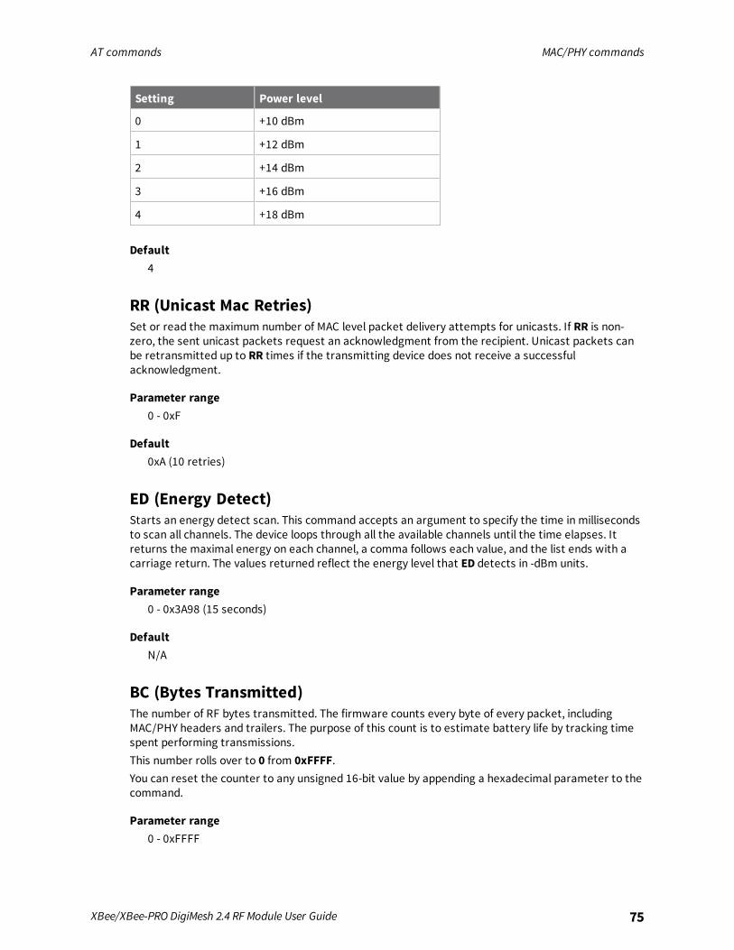
AT commands MAC/PHY commands
XBee/XBee-PRO DigiMesh 2.4 RF Module User Guide 75
Setting Power level
0 +10 dBm
1 +12 dBm
2 +14 dBm
3 +16 dBm
4 +18 dBm
Default4
RR (Unicast Mac Retries)Set or read the maximum number of MAC level packet delivery attempts for unicasts. If RR is non-zero, the sent unicast packets request an acknowledgment from the recipient. Unicast packets canbe retransmitted up to RR times if the transmitting device does not receive a successfulacknowledgment.
Parameter range0 - 0xF
Default0xA (10 retries)
ED (Energy Detect)Starts an energy detect scan. This command accepts an argument to specify the time in millisecondsto scan all channels. The device loops through all the available channels until the time elapses. Itreturns the maximal energy on each channel, a comma follows each value, and the list ends with acarriage return. The values returned reflect the energy level that ED detects in -dBm units.
Parameter range0 - 0x3A98 (15 seconds)
DefaultN/A
BC (Bytes Transmitted)The number of RF bytes transmitted. The firmware counts every byte of every packet, includingMAC/PHY headers and trailers. The purpose of this count is to estimate battery life by tracking timespent performing transmissions.This number rolls over to 0 from 0xFFFF.You can reset the counter to any unsigned 16-bit value by appending a hexadecimal parameter to thecommand.
Parameter range0 - 0xFFFF
AT commands MAC/PHY commands
XBee/XBee-PRO DigiMesh 2.4 RF Module User Guide 76
Default0
DB (Last Packet RSSI)Reports the RSSI in -dBm of the last received RF data packet. DB returns a hexadecimal value for the -dBmmeasurement.For example, if DB returns 0x60, then the RSSI of the last packet received was -96 dBm.DB only indicates the signal strength of the last hop. It does not provide an accurate qualitymeasurement for a multihop link.If the XBee/XBee-PRO DigiMesh 2.4 has been reset and has not yet received a packet, DB reports 0.This value is volatile (the value does not persist in the device's memory after a power-up sequence).
Parameter rangeN/A
Default0
GD (Good Packets Received)This count increments when a device receives a good frame with a valid MAC header on the RFinterface. Received MAC ACK packets do not increment this counter. Once the number reaches0xFFFF, it does not count further events.To reset the counter to any 16-bit unsigned value, append a hexadecimal parameter to the command.This value is volatile (the value does not persist in the device's memory after a power-up sequence).
Parameter rangeN/A
DefaultN/A
EA (MAC ACK Failure Count)The number of unicast transmissions that time out awaiting a MAC ACK. This can be up to RR +1timeouts per unicast when RR > 0.This count increments whenever a MAC ACK timeout occurs on a MAC-level unicast. When the numberreaches 0xFFFF, the firmware does not count further events.To reset the counter to any 16-bit unsigned value, append a hexadecimal parameter to the command.This value is volatile (the value does not persist in the device's memory after a power-up sequence).
Parameter range
Default
Parameter rangeN/A
AT commands Network commands
XBee/XBee-PRO DigiMesh 2.4 RF Module User Guide 77
DefaultN/A
TR (Transmission Failure Count)This value is volatile (the value does not persist in the device's memory after a power-up sequence).
Parameter rangeN/A
DefaultN/A
UA (Unicasts Attempted Count)The number of unicast transmissions expecting an acknowledgment (when RR > 0).This value is volatile (the value does not persist in the device's memory after a power-up sequence).
Parameter range0 - 0xFFFF
Default0
%H (MAC Unicast One Hop Time)The MAC unicast one hop time timeout in milliseconds. If you change the MAC parameters it canchange this value.
Parameter range[read-only]
DefaultN/A
%8 (MAC Broadcast One Hop Time)The MAC broadcast one hop time timeout in milliseconds. If you change MAC parameters, it canchange this value.
Parameter range[read-only]
DefaultN/A
Network commandsThe following commands are network commands.
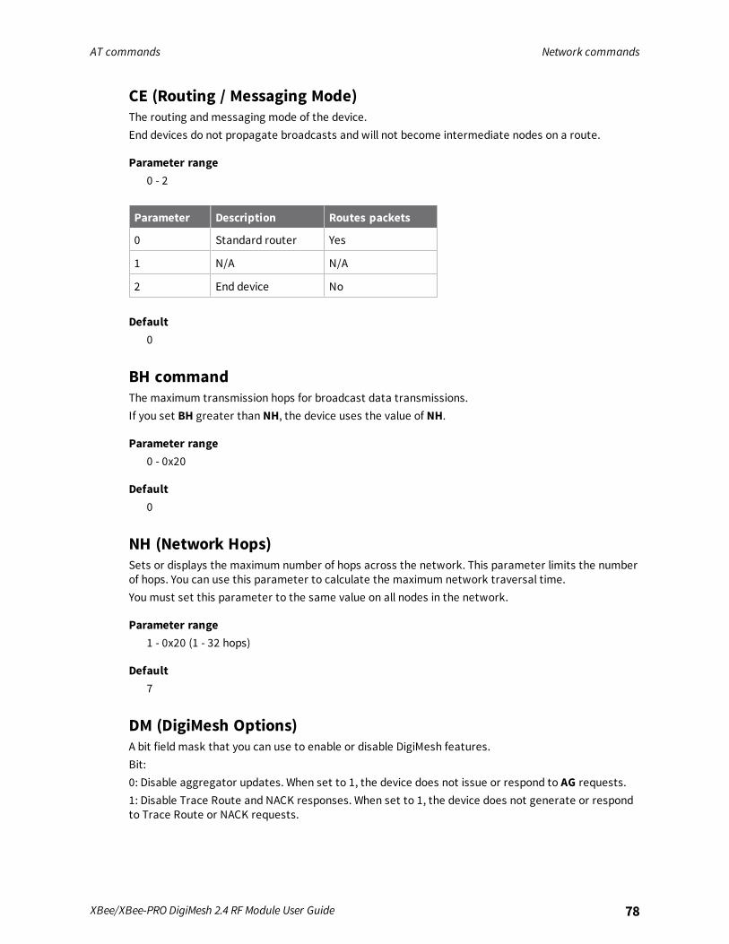
AT commands Network commands
XBee/XBee-PRO DigiMesh 2.4 RF Module User Guide 78
CE (Routing / Messaging Mode)The routing andmessaging mode of the device.End devices do not propagate broadcasts and will not become intermediate nodes on a route.
Parameter range0 - 2
Parameter Description Routes packets
0 Standard router Yes
1 N/A N/A
2 End device No
Default0
BH commandThe maximum transmission hops for broadcast data transmissions.If you set BH greater than NH, the device uses the value of NH.
Parameter range0 - 0x20
Default0
NH (Network Hops)Sets or displays the maximum number of hops across the network. This parameter limits the numberof hops. You can use this parameter to calculate the maximum network traversal time.You must set this parameter to the same value on all nodes in the network.
Parameter range1 - 0x20 (1 - 32 hops)
Default7
DM (DigiMesh Options)A bit field mask that you can use to enable or disable DigiMesh features.Bit:0: Disable aggregator updates. When set to 1, the device does not issue or respond to AG requests.1: Disable Trace Route and NACK responses. When set to 1, the device does not generate or respondto Trace Route or NACK requests.
AT commands Addressing commands
XBee/XBee-PRO DigiMesh 2.4 RF Module User Guide 79
Parameter range0 - 0x03 (bit field)
Default0
NN (Network Delay Slots)Set or read the maximum random number of network delay slots before rebroadcasting a networkpacket.One network delay slot is approximately 13 ms.
Parameter range1 - 0xA network delay slots
Default3
MR (Mesh Unicast Retries)Set or read the maximum number of network packet delivery attempts. If MR is non-zero, the packetsa device sends request a network acknowledgment, and can be resent up toMR+1 times if the devicedoes not receive an acknowledgment.Changing this value dramatically changes how long a route request takes.We recommend that you set this value to 1.If you set this parameter to 0, it disables network ACKs. Initially, the device can find routes, but aroute will never be repaired if it fails.
Parameter range0 - 7 mesh unicast retries
Default1
Addressing commandsThe following AT commands are addressing commands.
SH commandDisplays the upper 32 bits of the unique IEEE 64-bit extended address assigned to the product familyin the factory.
The 64-bit source address is always enabled. This value is read-only and it never changes.
Parameter range0 - 0xFFFFFFFF [read-only]
AT commands Addressing commands
XBee/XBee-PRO DigiMesh 2.4 RF Module User Guide 80
DefaultSet in the factory
SL commandDisplays the lower 32 bits of the unique IEEE 64-bit RF extended address assigned to the productfamily in the factory.The 64-bit source address is always enabled. This value is read-only and it never changes.
Parameter range0 - 0xFFFFFFFF [read-only]
DefaultSet in the factory
DH commandSet or read the upper 32 bits of the 64-bit destination address. When you combine DH with DL, itdefines the destination address that the device uses for transmissions in Transparent mode.The destination address is also used for I/O sampling in both Transparent and API modes.To transmit using a 16-bit address, set DH to 0 and DL less than 0xFFFF.0x000000000000FFFF is the broadcast address.
Parameter range0 - 0xFFFFFFFF
Default0
DL commandSet or display the lower 32 bits of the 64-bit destination address. When you combine DH with DL, itdefines the destination address that the device uses for transmissions in Transparent mode.The destination address is also used for I/O sampling in both Transparent and API modes.0x000000000000FFFF is the broadcast address.
Parameter range0 - 0xFFFFFFFF
Default0xFFFF
NI commandStores the node identifier string for a device, which is a user-defined name or description of thedevice. This can be up to 20 ASCII characters.
n XCTU prevents you from exceeding the string limit of 20 characters for this command. If youare using another software application to send the string, you can enter longer strings, but thesoftware on the device returns an error.
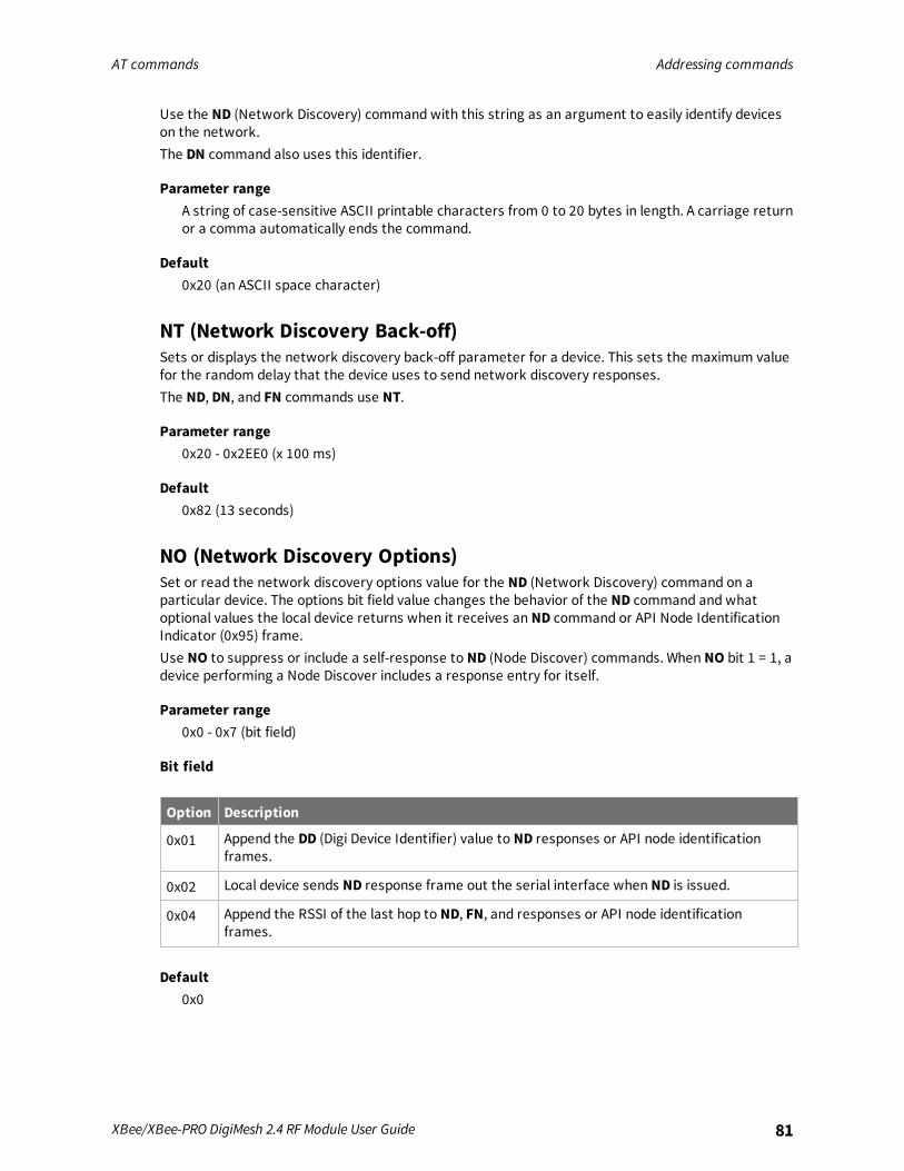
AT commands Addressing commands
XBee/XBee-PRO DigiMesh 2.4 RF Module User Guide 81
Use the ND (Network Discovery) command with this string as an argument to easily identify deviceson the network.The DN command also uses this identifier.
Parameter rangeA string of case-sensitive ASCII printable characters from 0 to 20 bytes in length. A carriage returnor a comma automatically ends the command.
Default0x20 (an ASCII space character)
NT (Network Discovery Back-off)Sets or displays the network discovery back-off parameter for a device. This sets the maximum valuefor the random delay that the device uses to send network discovery responses.The ND, DN, and FN commands use NT.
Parameter range0x20 - 0x2EE0 (x 100 ms)
Default0x82 (13 seconds)
NO (Network Discovery Options)Set or read the network discovery options value for the ND (Network Discovery) command on aparticular device. The options bit field value changes the behavior of the ND command and whatoptional values the local device returns when it receives an ND command or API Node IdentificationIndicator (0x95) frame.Use NO to suppress or include a self-response to ND (Node Discover) commands. When NO bit 1 = 1, adevice performing a Node Discover includes a response entry for itself.
Parameter range0x0 - 0x7 (bit field)
Bit field
Option Description
0x01 Append the DD (Digi Device Identifier) value to ND responses or API node identificationframes.
0x02 Local device sends ND response frame out the serial interface when ND is issued.
0x04 Append the RSSI of the last hop to ND, FN, and responses or API node identificationframes.
Default0x0
AT commands Diagnostic - addressing commands
XBee/XBee-PRO DigiMesh 2.4 RF Module User Guide 82
CI (Cluster ID)The application layer cluster ID value. The device uses this value as the cluster ID for all datatransmissions.If you set this value to 0x12 (loopback Cluster ID), the destination node echoes any transmittedpacket back to the source device.
Parameter range0 - 0xFFFF
Default0x11 (Transparent data cluster ID)
DE commandSets or displays the application layer destination ID value. The value is used as the destinationendpoint for all data transmissions. The default value (0xE8) is the Digi data endpoint.
Parameter range0 - 0xFF
Default0xE8
SE commandSets or displays the application layer source endpoint value. The value is used as the source endpointfor all data transmissions. The default value (0xE8) is the Digi data endpoint.Sets or displays the application layer source endpoint value used for data transmissions.This command only affects outgoing transmissions in transparent mode (AP=0).0xE8 is the Digi data endpoint used for outgoing data transmissions.0xE6 is the Digi device object endpoint used for configuration and commands.
Parameter range0 - 0xFF
Default0xE8
Diagnostic - addressing commandsThe following AT command is a Diagnostic - addressing command.
N? (Network Discovery Timeout)The maximum response time, in milliseconds, for ND (Network Discovery) responses and DN (DiscoverNode) responses. The timeout is based on the NT (Network Discovery Back-off Time) and the networkpropagation time.
AT commands Addressing discovery/configuration commands
XBee/XBee-PRO DigiMesh 2.4 RF Module User Guide 83
Parameter range[read-only]
Default0x3D6A
Addressing discovery/configuration commands
AG (Aggregator Support)The AG command sends a broadcast through the network that has the following effects on nodes thatreceive the broadcast:
n The receiving node establishes a DigiMesh route back to the originating node, if there is spacein the routing table.
n The DH and DL of the receiving node update to the address of the originating node if the AGparameter matches the current DH/DL of the receiving node.
n API-enabled devices with updated DH and DL send an Aggregate Addressing Update frame(0x8E) out the serial port.
Note The AG command is only available on products that support DigiMesh.
Parameter rangeAny 64-bit address
DefaultN/A
DN (Discover Node)Resolves an NI (Node identifier) string to a physical address (case sensitive).The following events occur after DN discovers the destination node:When DN is sent in Commandmode:
1. The device sets DL and DH to the extended (64-bit) address of the device with the matching NIstring.
2. The receiving device returns OK (or ERROR).
3. The device exits Commandmode to allow for immediate communication. If an ERROR isreceived, then Commandmode does not exit.
When DN is sent as a AT Command frame - 0x08:1. The receiving device returns 0xFFFE followed by its 64-bit extended addresses in a Remote
Command Response frame - 0x97.
2. The device returns an ERRORmessage if it is given without a destination node (that is withouta parameter) or if the given destination node does not respond within N?milliseconds.
AT commands Addressing discovery/configuration commands
XBee/XBee-PRO DigiMesh 2.4 RF Module User Guide 84
Parameter range20-byte ASCII string
DefaultN/A
ND (Network Discover)Discovers and reports all of the devices it finds on a network. If you sendND through a local API frame,each network node returns a separate AT Command Response (0x88) or Remote Command Response(0x97) frame, respectively.
Parameter rangeN/A
DefaultN/A
FN (Find Neighbors)Discovers and reports all devices found within immediate (1 hop) RF range. FN reports the followinginformation for each device it discovers:
MY<CR> (always 0xFFFE)SH<CR>SL<CR>NI<CR> (Variable length)PARENT_NETWORK ADDRESS<CR> (2 Bytes) (always 0xFFFE)DEVICE_TYPE<CR> (1 Byte: 0 = Coordinator, 1 = Router, 2 = End Device)STATUS<CR> (1 Byte: Reserved)PROFILE_ID<CR> (2 Bytes)MANUFACTURER_ID<CR> (2 Bytes)DIGI DEVICE TYPE<CR> (4 Bytes. Optionally included based on NO settings.)RSSI OF LAST HOP<CR> (1 Byte. Optionally included based on NO settings.)<CR>
If you send the FN command in Commandmode, after (NT*100) ms + overhead time, the commandends by returning a carriage return, represented by <CR>.If you send the FN command through a local AT Command (0x08) or remote AT command (0x17) APIframe, each response returns as a separate AT Command Response (0x88) or Remote CommandResponse (0x97) frame, respectively. The data consists of the bytes in the previous list without thecarriage return delimiters. The NI string ends in a 0x00 null character.
Parameter rangeN/A
DefaultN/A
AT commands Security commands
XBee/XBee-PRO DigiMesh 2.4 RF Module User Guide 85
Security commandsThe following AT commands are security commands.
EE (Encryption Enable)Enables or disables 128-bit Advanced Encryption Standard (AES) encryption.Set this command parameter the same on all devices in a network.
Parameter range0 - 1
Parameter Description
0 Encryption Disabled
1 Encryption Enabled
Default0
KY (AES Encryption Key)Sets the 16-byte network security key value that the device uses for encryption and decryption.This command is write-only. If you attempt to read KY, the device returns anOK status.Set this command parameter the same on all devices in a network.
Parameter range128-bit value
DefaultN/A
Serial interfacing commandsThe following AT commands are serial interfacing commands.
BD (Baud Rate)Sets or displays the serial interface baud rate for communication between the device's serial port andthe host.To request non-standard baud rates with values above 0x80, you can use the Serial Console toolbar inXCTU to configure the serial connection (if the console is connected), or click the Connect button (ifthe console is not yet connected).When you send non-standard baud rates to a device, it stores the closest interface data raterepresented by the number in the BD register. Read the BD command by sending ATBDwithout aparameter value, and the device returns the value stored in the BD register.
Parameter rangeStandard baud rates: 0x0 - 0x7
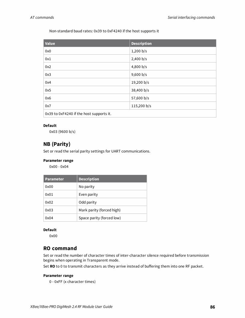
AT commands Serial interfacing commands
XBee/XBee-PRO DigiMesh 2.4 RF Module User Guide 86
Non-standard baud rates: 0x39 to 0xF4240 if the host supports it
Value Description
0x0 1,200 b/s
0x1 2,400 b/s
0x2 4,800 b/s
0x3 9,600 b/s
0x4 19,200 b/s
0x5 38,400 b/s
0x6 57,600 b/s
0x7 115,200 b/s
0x39 to 0xF4240 if the host supports it.
Default0x03 (9600 b/s)
NB (Parity)Set or read the serial parity settings for UART communications.
Parameter range0x00 - 0x04
Parameter Description
0x00 No parity
0x01 Even parity
0x02 Odd parity
0x03 Mark parity (forced high)
0x04 Space parity (forced low)
Default0x00
RO commandSet or read the number of character times of inter-character silence required before transmissionbegins when operating in Transparent mode.Set RO to 0 to transmit characters as they arrive instead of buffering them into one RF packet.
Parameter range0 - 0xFF (x character times)
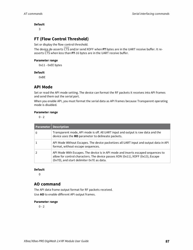
AT commands Serial interfacing commands
XBee/XBee-PRO DigiMesh 2.4 RF Module User Guide 87
Default3
FT (Flow Control Threshold)Set or display the flow control threshold.The device de-asserts CTS and/or send XOFF when FT bytes are in the UART receive buffer. It re-asserts CTS when less than FT-16 bytes are in the UART receive buffer.
Parameter range0x11 - 0xEE bytes
Default0xBE
API ModeSet or read the API mode setting. The device can format the RF packets it receives into API framesand send them out the serial port.When you enable API, you must format the serial data as API frames because Transparent operatingmode is disabled.
Parameter range0 - 2
Parameter Description
0 Transparent mode, API mode is off. All UART input and output is raw data and thedevice uses the RO parameter to delineate packets.
1 API Mode Without Escapes. The device packetizes all UART input and output data in APIformat, without escape sequences.
2 API Mode With Escapes. The device is in API mode and inserts escaped sequences toallow for control characters. The device passes XON (0x11), XOFF (0x13), Escape(0x7D), and start delimiter 0x7E as data.
Default0
AO commandThe API data frame output format for RF packets received.Use AO to enable different API output frames.
Parameter range0 - 2

AT commands I/O settings commands
XBee/XBee-PRO DigiMesh 2.4 RF Module User Guide 88
Parameter Description
0 API Rx Indicator - 0x90, this is for standard data frames.
1 API Explicit Rx Indicator - 0x91, this is for Explicit Addressing data frames.
Default0
I/O settings commandsThe following AT commands are I/O settings commands.
CB commandUse CB to simulate commissioning pushbutton presses in software.Set the parameter value to the number of button presses that you want to simulate. For example,send CB1 to perform the action of pressing the Commissioning Pushbutton once.See The Commissioning Pushbutton.See Commissioning pushbutton.
Parameter range0 - 4
DefaultN/A
D0 (DIO0/AD0)Sets or displays the DIO0/AD0 configuration (pin 20).
Parameter range0 - 5
Parameter Description
0 Disabled
1 Commissioning Pushbutton
2 ADC
3 Digital input
4 Digital output, low
5 Digital output, high
Default1
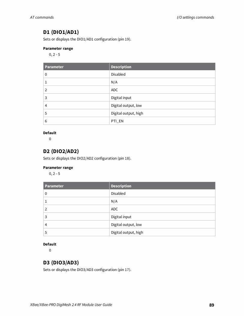
AT commands I/O settings commands
XBee/XBee-PRO DigiMesh 2.4 RF Module User Guide 89
D1 (DIO1/AD1)Sets or displays the DIO1/AD1 configuration (pin 19).
Parameter range0, 2 - 5
Parameter Description
0 Disabled
1 N/A
2 ADC
3 Digital input
4 Digital output, low
5 Digital output, high
6 PTI_EN
Default0
D2 (DIO2/AD2)Sets or displays the DIO2/AD2 configuration (pin 18).
Parameter range0, 2 - 5
Parameter Description
0 Disabled
1 N/A
2 ADC
3 Digital input
4 Digital output, low
5 Digital output, high
Default0
D3 (DIO3/AD3)Sets or displays the DIO3/AD3 configuration (pin 17).
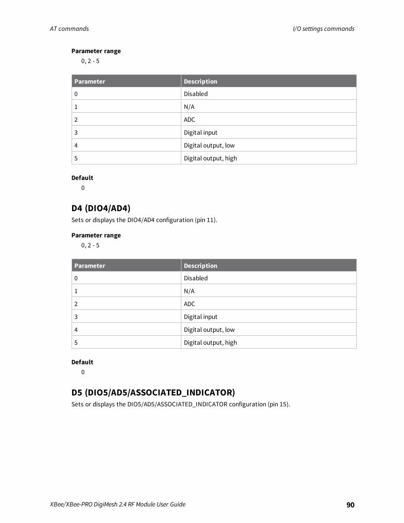
AT commands I/O settings commands
XBee/XBee-PRO DigiMesh 2.4 RF Module User Guide 90
Parameter range0, 2 - 5
Parameter Description
0 Disabled
1 N/A
2 ADC
3 Digital input
4 Digital output, low
5 Digital output, high
Default0
D4 (DIO4/AD4)Sets or displays the DIO4/AD4 configuration (pin 11).
Parameter range0, 2 - 5
Parameter Description
0 Disabled
1 N/A
2 ADC
3 Digital input
4 Digital output, low
5 Digital output, high
Default0
D5 (DIO5/AD5/ASSOCIATED_INDICATOR)Sets or displays the DIO5/AD5/ASSOCIATED_INDICATOR configuration (pin 15).
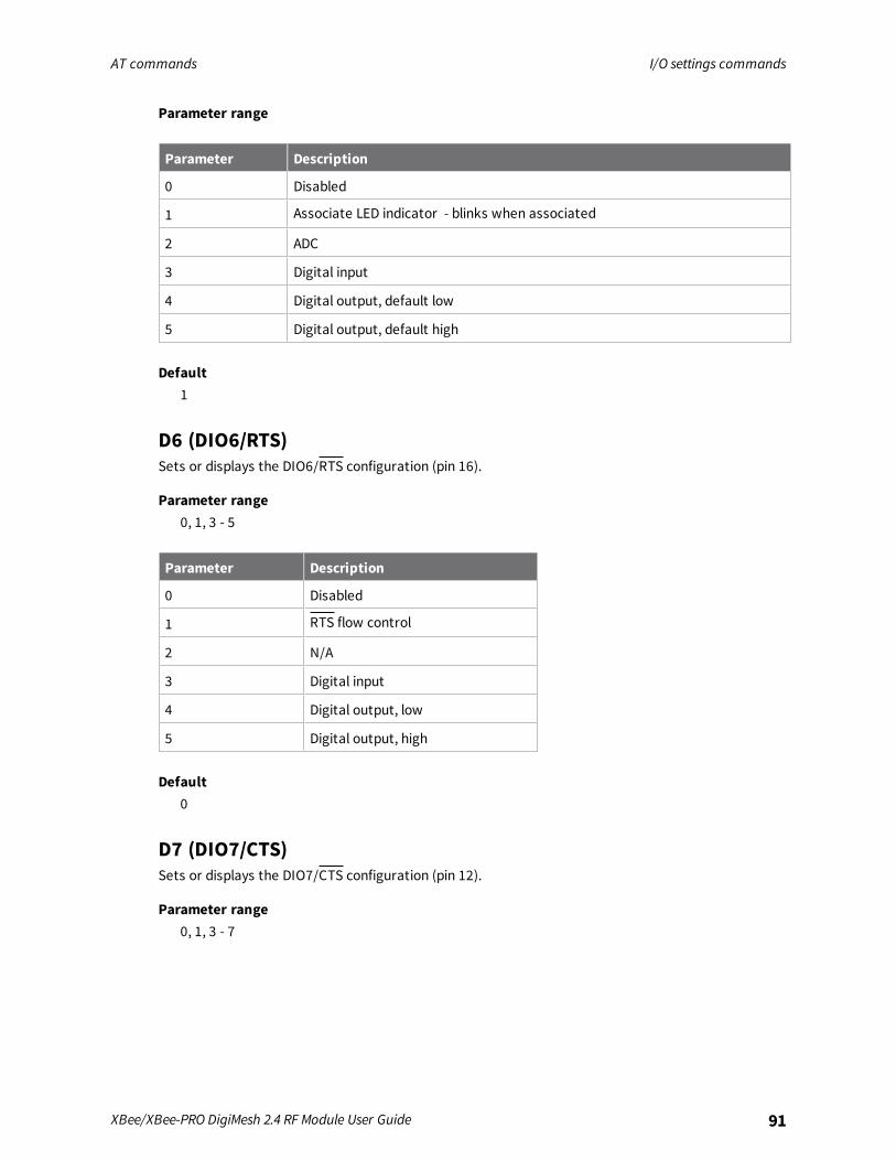
AT commands I/O settings commands
XBee/XBee-PRO DigiMesh 2.4 RF Module User Guide 91
Parameter range
Parameter Description
0 Disabled
1 Associate LED indicator - blinks when associated
2 ADC
3 Digital input
4 Digital output, default low
5 Digital output, default high
Default1
D6 (DIO6/RTS)Sets or displays the DIO6/RTS configuration (pin 16).
Parameter range0, 1, 3 - 5
Parameter Description
0 Disabled
1 RTS flow control
2 N/A
3 Digital input
4 Digital output, low
5 Digital output, high
Default0
D7 (DIO7/CTS)Sets or displays the DIO7/CTS configuration (pin 12).
Parameter range0, 1, 3 - 7
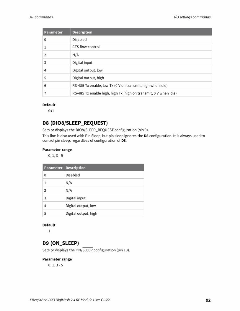
AT commands I/O settings commands
XBee/XBee-PRO DigiMesh 2.4 RF Module User Guide 92
Parameter Description
0 Disabled
1 CTS flow control
2 N/A
3 Digital input
4 Digital output, low
5 Digital output, high
6 RS-485 Tx enable, low Tx (0 V on transmit, high when idle)
7 RS-485 Tx enable high, high Tx (high on transmit, 0 V when idle)
Default0x1
D8 (DIO8/SLEEP_REQUEST)Sets or displays the DIO8/SLEEP_REQUEST configuration (pin 9).This line is also used with Pin Sleep, but pin sleep ignores the D8 configuration. It is always used tocontrol pin sleep, regardless of configuration of D8.
Parameter range0, 1, 3 - 5
Parameter Description
0 Disabled
1 N/A
2 N/A
3 Digital input
4 Digital output, low
5 Digital output, high
Default1
D9 (ON_SLEEP)Sets or displays the ON/SLEEP configuration (pin 13).
Parameter range0, 1, 3 - 5
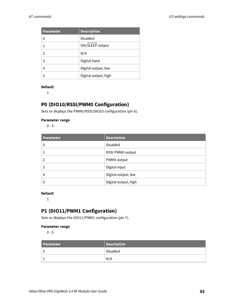
AT commands I/O settings commands
XBee/XBee-PRO DigiMesh 2.4 RF Module User Guide 93
Parameter Description
0 Disabled
1 ON/SLEEP output
2 N/A
3 Digital input
4 Digital output, low
5 Digital output, high
Default1
P0 (DIO10/RSSI/PWM0 Configuration)Sets or displays the PWM0/RSSI/DIO10 configuration (pin 6).
Parameter range0 - 5
Parameter Description
0 Disabled
1 RSSI PWM0 output
2 PWM0 output
3 Digital input
4 Digital output, low
5 Digital output, high
Default1
P1 (DIO11/PWM1 Configuration)Sets or displays the DIO11/PWM1 configuration (pin 7).
Parameter range0 - 5
Parameter Description
0 Disabled
1 N/A
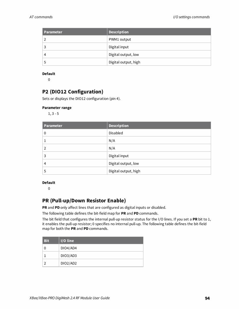
AT commands I/O settings commands
XBee/XBee-PRO DigiMesh 2.4 RF Module User Guide 94
Parameter Description
2 PWM1 output
3 Digital input
4 Digital output, low
5 Digital output, high
Default0
P2 (DIO12 Configuration)Sets or displays the DIO12 configuration (pin 4).
Parameter range1, 3 - 5
Parameter Description
0 Disabled
1 N/A
2 N/A
3 Digital input
4 Digital output, low
5 Digital output, high
Default0
PR (Pull-up/Down Resistor Enable)PR and PD only affect lines that are configured as digital inputs or disabled.The following table defines the bit-field map for PR and PD commands.The bit field that configures the internal pull-up resistor status for the I/O lines. If you set a PR bit to 1,it enables the pull-up resistor; 0 specifies no internal pull-up. The following table defines the bit-fieldmap for both the PR and PD commands.
Bit I/O line
0 DIO4/AD4
1 DIO3/AD3
2 DIO2/AD2
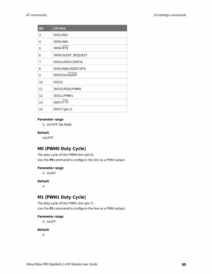
AT commands I/O settings commands
XBee/XBee-PRO DigiMesh 2.4 RF Module User Guide 95
Bit I/O line
3 DIO1/AD1
4 DIO0/AD0
5 DIO6/RTS
6 DIO8/SLEEP_REQUEST
7 DIO14/DIN/CONFIG
8 DIO5/AD6/ASSOCIATE
9 DIO9/On/SLEEP
10 DIO12
11 DIO10/RSSI/PWM0
12 DIO11/PWM1
13 DIO7/CTS
14 DOUT (pin 2)
Parameter range0 - 0x7FFF (bit field)
Default0x1FFF
M0 (PWM0 Duty Cycle)The duty cycle of the PWM0 line (pin 6).Use the P0 command to configure the line as a PWM output.
Parameter range0 - 0x3FF
Default0
M1 (PWM1 Duty Cycle)The duty cycle of the PWM1 line (pin 7).Use the P1 command to configure the line as a PWM output.
Parameter range0 - 0x3FF
Default0
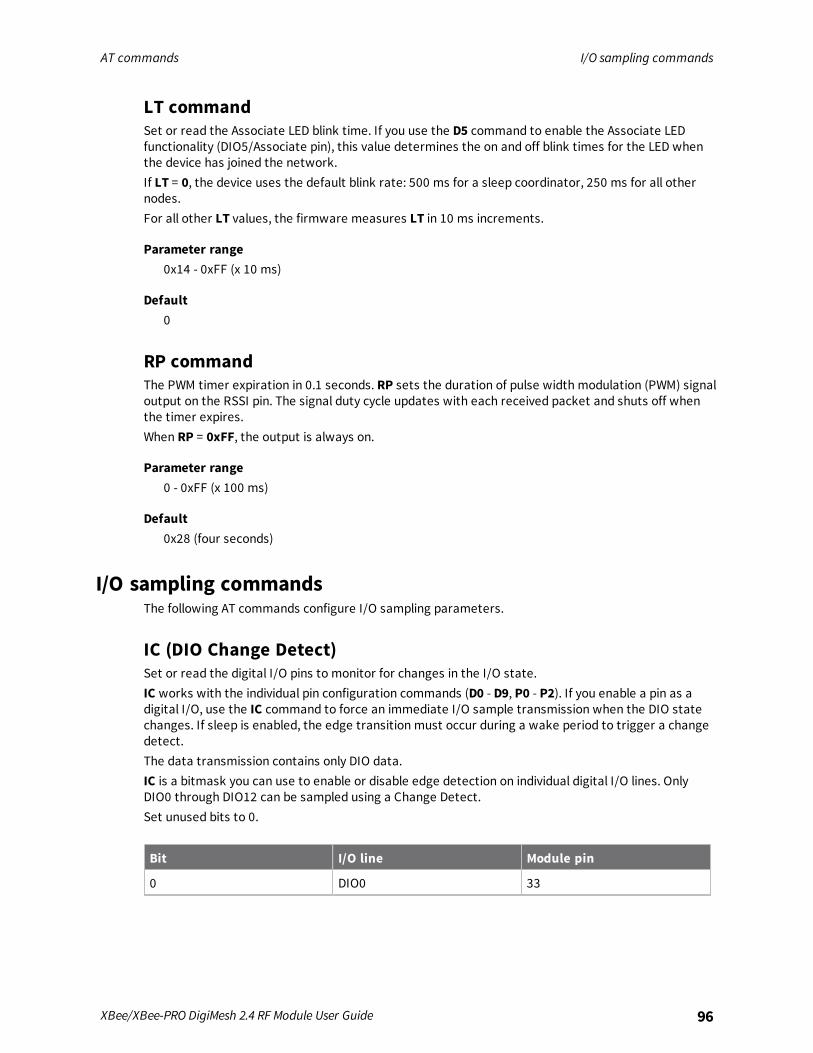
AT commands I/O sampling commands
XBee/XBee-PRO DigiMesh 2.4 RF Module User Guide 96
LT commandSet or read the Associate LED blink time. If you use the D5 command to enable the Associate LEDfunctionality (DIO5/Associate pin), this value determines the on and off blink times for the LED whenthe device has joined the network.If LT = 0, the device uses the default blink rate: 500 ms for a sleep coordinator, 250 ms for all othernodes.For all other LT values, the firmware measures LT in 10 ms increments.
Parameter range0x14 - 0xFF (x 10 ms)
Default0
RP commandThe PWM timer expiration in 0.1 seconds. RP sets the duration of pulse width modulation (PWM) signaloutput on the RSSI pin. The signal duty cycle updates with each received packet and shuts off whenthe timer expires.When RP = 0xFF, the output is always on.
Parameter range0 - 0xFF (x 100 ms)
Default0x28 (four seconds)
I/O sampling commandsThe following AT commands configure I/O sampling parameters.
IC (DIO Change Detect)Set or read the digital I/O pins to monitor for changes in the I/O state.IC works with the individual pin configuration commands (D0 - D9, P0 - P2). If you enable a pin as adigital I/O, use the IC command to force an immediate I/O sample transmission when the DIO statechanges. If sleep is enabled, the edge transition must occur during a wake period to trigger a changedetect.The data transmission contains only DIO data.IC is a bitmask you can use to enable or disable edge detection on individual digital I/O lines. OnlyDIO0 through DIO12 can be sampled using a Change Detect.Set unused bits to 0.
Bit I/O line Module pin
0 DIO0 33
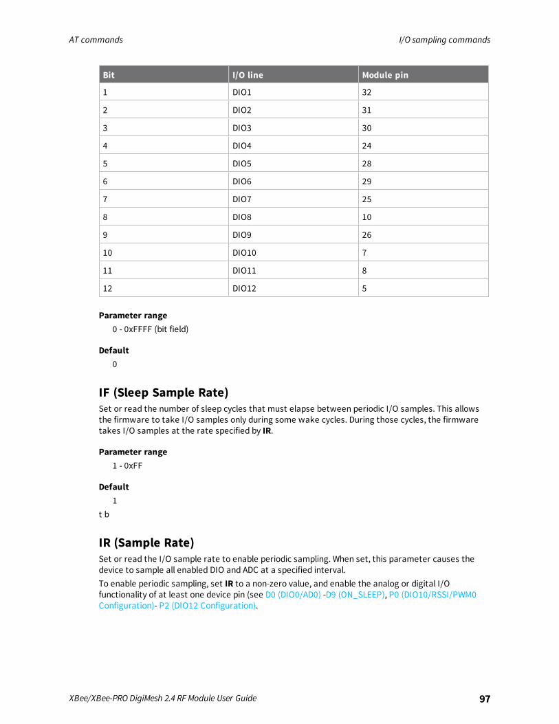
AT commands I/O sampling commands
XBee/XBee-PRO DigiMesh 2.4 RF Module User Guide 97
Bit I/O line Module pin
1 DIO1 32
2 DIO2 31
3 DIO3 30
4 DIO4 24
5 DIO5 28
6 DIO6 29
7 DIO7 25
8 DIO8 10
9 DIO9 26
10 DIO10 7
11 DIO11 8
12 DIO12 5
Parameter range0 - 0xFFFF (bit field)
Default0
IF (Sleep Sample Rate)Set or read the number of sleep cycles that must elapse between periodic I/O samples. This allowsthe firmware to take I/O samples only during some wake cycles. During those cycles, the firmwaretakes I/O samples at the rate specified by IR.
Parameter range1 - 0xFF
Default1
t b
IR (Sample Rate)Set or read the I/O sample rate to enable periodic sampling. When set, this parameter causes thedevice to sample all enabled DIO and ADC at a specified interval.To enable periodic sampling, set IR to a non-zero value, and enable the analog or digital I/Ofunctionality of at least one device pin (see D0 (DIO0/AD0) -D9 (ON_SLEEP), P0 (DIO10/RSSI/PWM0Configuration)- P2 (DIO12 Configuration).
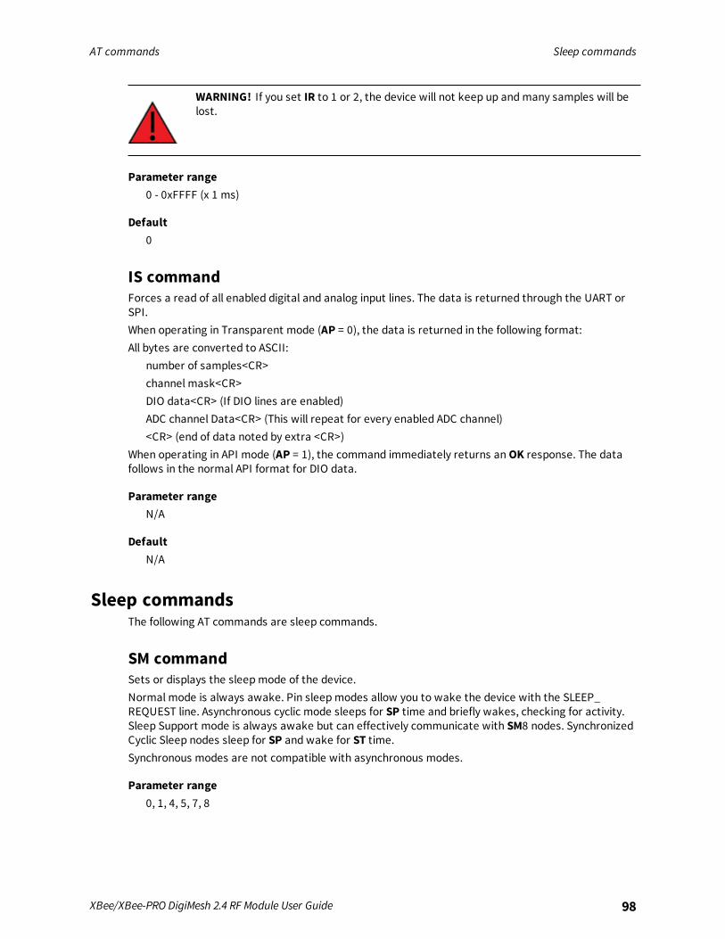
AT commands Sleep commands
XBee/XBee-PRO DigiMesh 2.4 RF Module User Guide 98
WARNING! If you set IR to 1 or 2, the device will not keep up andmany samples will belost.
Parameter range0 - 0xFFFF (x 1 ms)
Default0
IS commandForces a read of all enabled digital and analog input lines. The data is returned through the UART orSPI.When operating in Transparent mode (AP = 0), the data is returned in the following format:All bytes are converted to ASCII:
number of samples<CR>channel mask<CR>DIO data<CR> (If DIO lines are enabled)ADC channel Data<CR> (This will repeat for every enabled ADC channel)<CR> (end of data noted by extra <CR>)
When operating in API mode (AP = 1), the command immediately returns anOK response. The datafollows in the normal API format for DIO data.
Parameter rangeN/A
DefaultN/A
Sleep commandsThe following AT commands are sleep commands.
SM commandSets or displays the sleepmode of the device.Normal mode is always awake. Pin sleepmodes allow you to wake the device with the SLEEP_REQUEST line. Asynchronous cyclic mode sleeps for SP time and briefly wakes, checking for activity.Sleep Support mode is always awake but can effectively communicate with SM8 nodes. SynchronizedCyclic Sleep nodes sleep for SP and wake for ST time.Synchronous modes are not compatible with asynchronous modes.
Parameter range0, 1, 4, 5, 7, 8
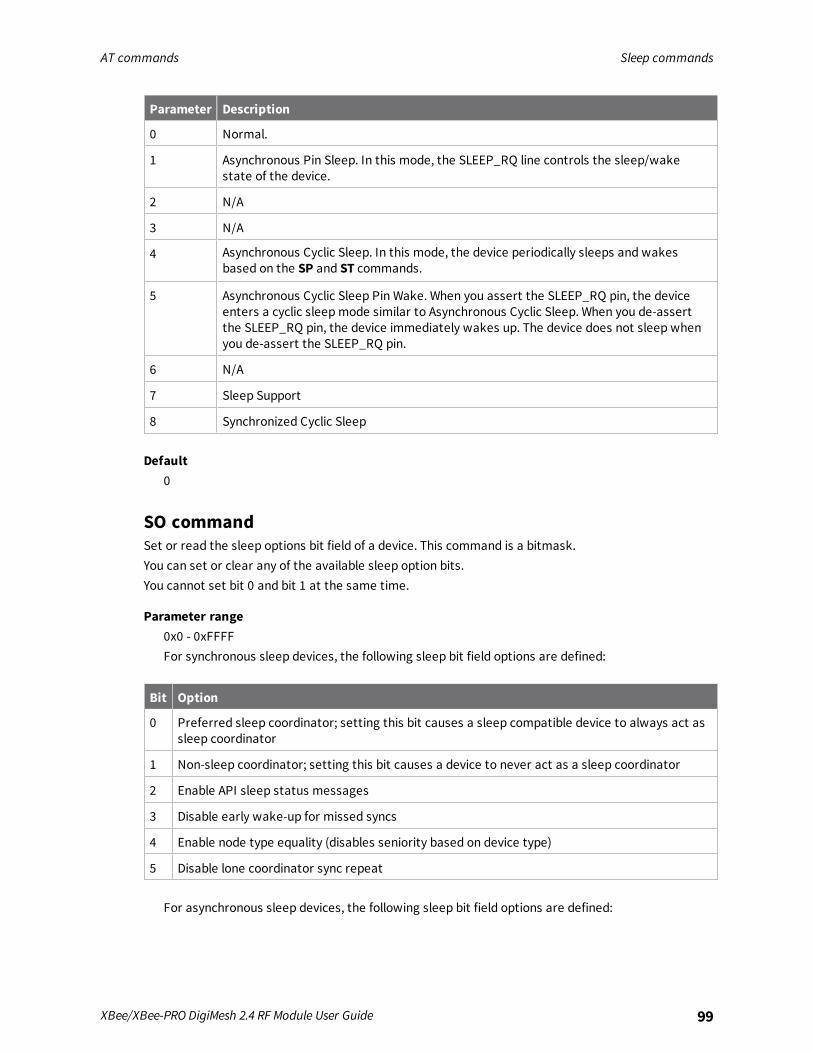
AT commands Sleep commands
XBee/XBee-PRO DigiMesh 2.4 RF Module User Guide 99
Parameter Description
0 Normal.
1 Asynchronous Pin Sleep. In this mode, the SLEEP_RQ line controls the sleep/wakestate of the device.
2 N/A
3 N/A
4 Asynchronous Cyclic Sleep. In this mode, the device periodically sleeps and wakesbased on the SP and ST commands.
5 Asynchronous Cyclic Sleep Pin Wake. When you assert the SLEEP_RQ pin, the deviceenters a cyclic sleepmode similar to Asynchronous Cyclic Sleep. When you de-assertthe SLEEP_RQ pin, the device immediately wakes up. The device does not sleep whenyou de-assert the SLEEP_RQ pin.
6 N/A
7 Sleep Support
8 Synchronized Cyclic Sleep
Default0
SO commandSet or read the sleep options bit field of a device. This command is a bitmask.You can set or clear any of the available sleep option bits.You cannot set bit 0 and bit 1 at the same time.
Parameter range0x0 - 0xFFFFFor synchronous sleep devices, the following sleep bit field options are defined:
Bit Option
0 Preferred sleep coordinator; setting this bit causes a sleep compatible device to always act assleep coordinator
1 Non-sleep coordinator; setting this bit causes a device to never act as a sleep coordinator
2 Enable API sleep status messages
3 Disable early wake-up for missed syncs
4 Enable node type equality (disables seniority based on device type)
5 Disable lone coordinator sync repeat
For asynchronous sleep devices, the following sleep bit field options are defined:

AT commands Sleep commands
XBee/XBee-PRO DigiMesh 2.4 RF Module User Guide 100
Bit Option
8 Always wake for ST time
Default0x2 (non-sleep coordinator)
SN commandSet or read the number of sleep periods value. This command controls the number of sleep periodsthat must elapse between assertions of the ON_SLEEP line during the wake time of AsynchronousCyclic Sleep. This allows external circuitry to sleep longer than the SP time.During cycles when ON_SLEEP is de-asserted, the device wakes up and checks for any serial or RFdata. If it receives any such data, then it asserts the ON_SLEEP line and the device wakes up fully.Otherwise, the device returns to sleep after checking.This command does not work with synchronous sleep devices.
Parameter range1 - 0xFFFF
Default1
ExampleSet to 1 to set ON_SLEEP high after each SP time (default).If SN = 3, the ON_SLEEP line asserts only every third wakeup; SN = 9, every ninth wakeup; and soforth.
SP (Sleep Time)Sets or displays the device's sleep time. This command defines the amount of time the device sleepsper cycle.
Parameter range0x1 - 0x15F900 (x 10 ms)
Default0xC8
ST (Wake Time)Sets or displays the wake time of the device.For devices in asynchronous sleep, ST defines the amount of time that a device stays awake after itreceives RF or serial data.For devices in synchronous sleep, ST defines the amount of time that a device stays awake whenoperating in cyclic sleepmode. The command adjusts the value upwards automatically if it is too smallto function properly based on other settings.For devices in synchronous sleep, the minimum wake time is a function of MT, SP, NH, NN, andplatform dependent values. If you increase SP, NH, NN, or MT, the ST value raises automatically. Themaximum value is one hour (0x36EE80 ms).
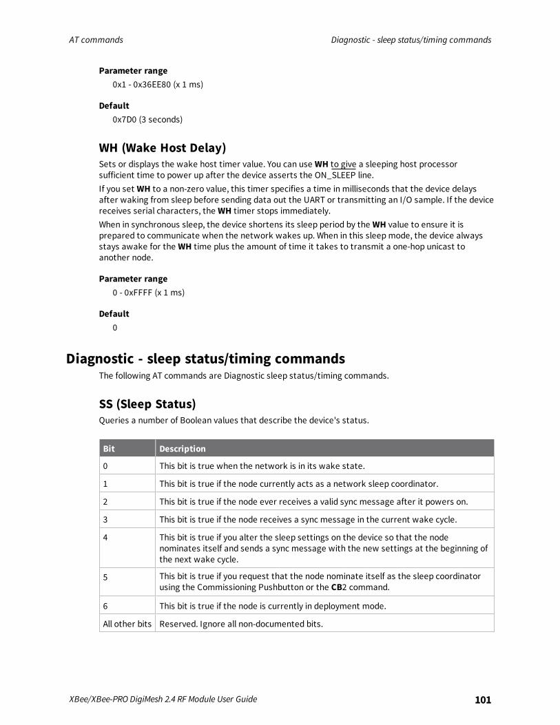
AT commands Diagnostic - sleep status/timing commands
XBee/XBee-PRO DigiMesh 2.4 RF Module User Guide 101
Parameter range0x1 - 0x36EE80 (x 1 ms)
Default0x7D0 (3 seconds)
WH (Wake Host Delay)Sets or displays the wake host timer value. You can use WH to give a sleeping host processorsufficient time to power up after the device asserts the ON_SLEEP line.If you set WH to a non-zero value, this timer specifies a time in milliseconds that the device delaysafter waking from sleep before sending data out the UART or transmitting an I/O sample. If the devicereceives serial characters, the WH timer stops immediately.When in synchronous sleep, the device shortens its sleep period by the WH value to ensure it isprepared to communicate when the network wakes up. When in this sleepmode, the device alwaysstays awake for the WH time plus the amount of time it takes to transmit a one-hop unicast toanother node.
Parameter range0 - 0xFFFF (x 1 ms)
Default0
Diagnostic - sleep status/timing commandsThe following AT commands are Diagnostic sleep status/timing commands.
SS (Sleep Status)Queries a number of Boolean values that describe the device's status.
Bit Description
0 This bit is true when the network is in its wake state.
1 This bit is true if the node currently acts as a network sleep coordinator.
2 This bit is true if the node ever receives a valid sync message after it powers on.
3 This bit is true if the node receives a sync message in the current wake cycle.
4 This bit is true if you alter the sleep settings on the device so that the nodenominates itself and sends a sync message with the new settings at the beginning ofthe next wake cycle.
5 This bit is true if you request that the node nominate itself as the sleep coordinatorusing the Commissioning Pushbutton or the CB2 command.
6 This bit is true if the node is currently in deployment mode.
All other bits Reserved. Ignore all non-documented bits.
AT commands Diagnostic - sleep status/timing commands
XBee/XBee-PRO DigiMesh 2.4 RF Module User Guide 102
Parameter rangeN/A[read-only]
DefaultN/A
OS (Operating Sleep Time)Reads the current network sleep time that the device is synchronized to, in units of 10 milliseconds. Ifthe device has not been synchronized, thenOS returns the value of SP.If the device synchronizes with a sleeping router network,OSmay differ from SP.
Parameter rangeN/A
DefaultN/A
OW (Operating Wake Time)Reads the current network wake time that a device is synchronized to, in 1 ms units.If the device has not been synchronized, thenOW returns the value of ST.If the device synchronizes with a sleeping router network,OW may differ from ST.
Parameter rangeN/A
DefaultN/A
MS (Missed Sync Messages)Reads the number of sleep or wake cycles since the device received a sync message.
Parameter rangeN/A
DefaultN/A
SQ (Missed Sleep Sync Count)Counts the number of sleep cycles in which the device does not receive a sleep sync.Set the value to 0 to reset this value.When the value reaches 0xFFFF it does not increment anymore.
Parameter rangeN/A
AT commands Command mode options
XBee/XBee-PRO DigiMesh 2.4 RF Module User Guide 103
DefaultN/A
Command mode optionsThe following commands are Commandmode option commands.
CC (Command Character)The character value the device uses to enter Commandmode.The default value (0x2B) is the ASCII code for the plus (+) character. You must enter it three timeswithin the guard time to enter Commandmode. To enter Commandmode, there is also a requiredperiod of silence before and after the command sequence characters of the Commandmodesequence (GT + CC + GT). The period of silence prevents inadvertently entering Commandmode.
Parameter range0 - 0xFFRecommended: 0x20 - 0x7F (ASCII)
Default0x2B (the ASCII plus character: +)
CT commandSets or displays the Commandmode timeout parameter. If a device does not receive any validcommands within this time period, it returns to Idle mode from Commandmode.
Parameter range2 - 0x1770 (x 100 ms)
Default0x64 (10 seconds)
CN commandImmediately exits Command Mode and applies pending changes.
Parameter rangeN/A
DefaultN/A
GT commandSet the required period of silence before and after the command sequence characters of theCommandmode sequence (GT + CC + GT). The period of silence prevents inadvertently enteringCommandmode.
AT commands Firmware version/information commands
XBee/XBee-PRO DigiMesh 2.4 RF Module User Guide 104
Parameter range0x2 - 0xCE4 (x 1 ms)
Default0x3E8 (one second)
Firmware version/information commandsThe following AT commands are firmware commands.
VL commandShows detailed version information including the application build date and time.
Parameter rangeN/A
DefaultN/A
VR commandReads the firmware version on a device.
Parameter range0 - 0xFFFFFFFF [read-only]
DefaultSet in the factory
HV commandDisplay the hardware version number of the device.
Parameter range0 - 0xFFFF [read-only]
DefaultSet in firmware
DD commandStores the Digi device type identifier value. Use this value to differentiate between multiple XBeedevices.If you change DD, RE command will not restore defaults. The only way to get DD back to default valuesis to explicitly set it to defaults.
Parameter range0 - 0xFFFFFFFF
AT commands Firmware version/information commands
XBee/XBee-PRO DigiMesh 2.4 RF Module User Guide 105
Default0x50000
NP (Maximum Packet Payload Bytes)Reads the maximum number of RF payload bytes that you can send in a transmission.Using APS encryption (API transmit option bit enabled), reduces the maximum payload size by 9 bytes.Using source routing (AR < 0xFF), further reduces the maximum payload size.
Note NP returns a hexadecimal value. For example, if NP returns 0x54, this is equivalent to 84 bytes.
Parameter range0 - 0xFFFF (bytes) [read-only]
DefaultN/A
CK (Configuration CRC)Displays the cyclic redundancy check (CRC) of the current AT command configuration settings.This command allows you to detect an unexpected configuration change on a device. Use the codethat the device returns to determine if a node has the configuration you want.After a firmware update this commandmay return a different value.
Parameter range0 - 0xFFFFFFFF
DefaultN/A
Operate in API mode
API mode overview 107Frame descriptions 111
XBee/XBee-PRO DigiMesh 2.4 RF Module User Guide 106
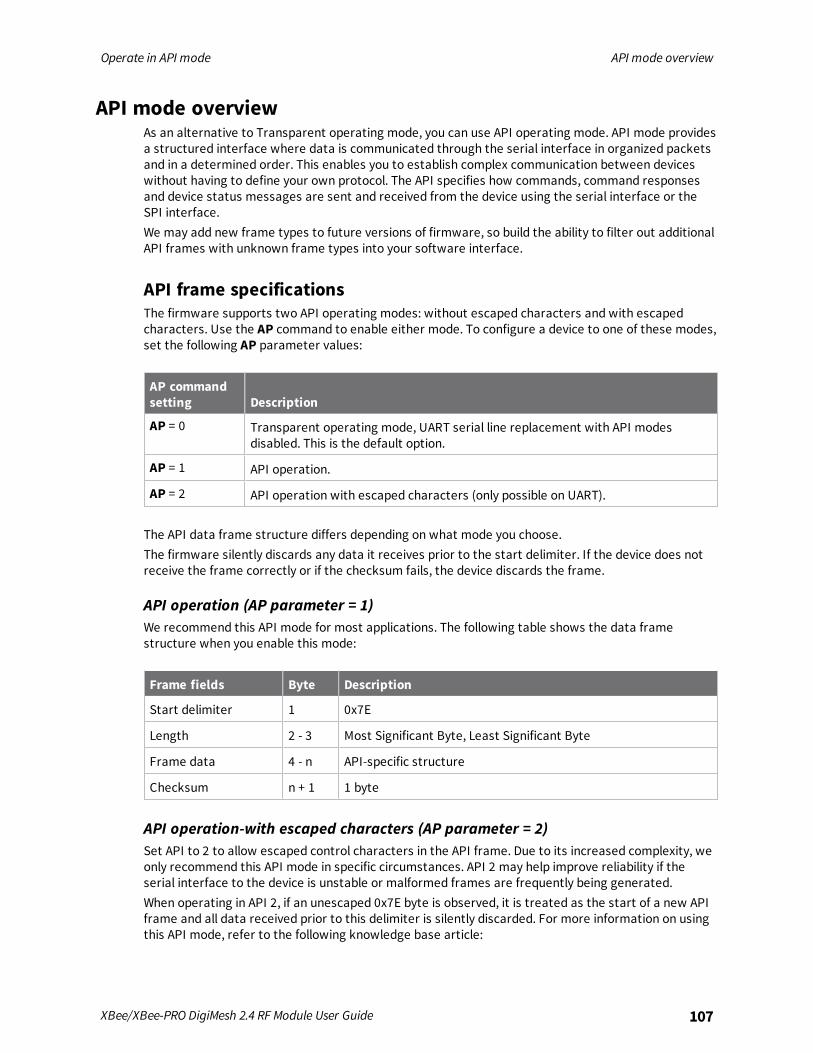
Operate in API mode API mode overview
XBee/XBee-PRO DigiMesh 2.4 RF Module User Guide 107
API mode overviewAs an alternative to Transparent operating mode, you can use API operating mode. API mode providesa structured interface where data is communicated through the serial interface in organized packetsand in a determined order. This enables you to establish complex communication between deviceswithout having to define your own protocol. The API specifies how commands, command responsesand device status messages are sent and received from the device using the serial interface or theSPI interface.We may add new frame types to future versions of firmware, so build the ability to filter out additionalAPI frames with unknown frame types into your software interface.
API frame specificationsThe firmware supports two API operating modes: without escaped characters and with escapedcharacters. Use the AP command to enable either mode. To configure a device to one of these modes,set the following AP parameter values:
AP commandsetting Description
AP = 0 Transparent operating mode, UART serial line replacement with API modesdisabled. This is the default option.
AP = 1 API operation.
AP = 2 API operation with escaped characters (only possible on UART).
The API data frame structure differs depending on what mode you choose.The firmware silently discards any data it receives prior to the start delimiter. If the device does notreceive the frame correctly or if the checksum fails, the device discards the frame.
API operation (AP parameter = 1)We recommend this API mode for most applications. The following table shows the data framestructure when you enable this mode:
Frame fields Byte Description
Start delimiter 1 0x7E
Length 2 - 3 Most Significant Byte, Least Significant Byte
Frame data 4 - n API-specific structure
Checksum n + 1 1 byte
API operation-with escaped characters (AP parameter = 2)Set API to 2 to allow escaped control characters in the API frame. Due to its increased complexity, weonly recommend this API mode in specific circumstances. API 2 may help improve reliability if theserial interface to the device is unstable or malformed frames are frequently being generated.When operating in API 2, if an unescaped 0x7E byte is observed, it is treated as the start of a new APIframe and all data received prior to this delimiter is silently discarded. For more information on usingthis API mode, refer to the following knowledge base article:
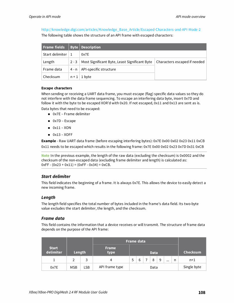
Operate in API mode API mode overview
XBee/XBee-PRO DigiMesh 2.4 RF Module User Guide 108
http://knowledge.digi.com/articles/Knowledge_Base_Article/Escaped-Characters-and-API-Mode-2The following table shows the structure of an API frame with escaped characters:
Frame fields Byte Description
Start delimiter 1 0x7E
Length 2 - 3 Most Significant Byte, Least Significant Byte Characters escaped if needed
Frame data 4 - n API-specific structure
Checksum n + 1 1 byte
Escape charactersWhen sending or receiving a UART data frame, you must escape (flag) specific data values so they donot interfere with the data frame sequencing. To escape an interfering data byte, insert 0x7D andfollow it with the byte to be escaped XOR’d with 0x20. If not escaped, 0x11 and 0x13 are sent as is.Data bytes that need to be escaped:
n 0x7E – Frame delimiter
n 0x7D – Escape
n 0x11 – XON
n 0x13 – XOFF
Example - Raw UART data frame (before escaping interfering bytes): 0x7E 0x00 0x02 0x23 0x11 0xCB0x11 needs to be escaped which results in the following frame: 0x7E 0x00 0x02 0x23 0x7D 0x31 0xCB
Note In the previous example, the length of the raw data (excluding the checksum) is 0x0002 and thechecksum of the non-escaped data (excluding frame delimiter and length) is calculated as:0xFF - (0x23 + 0x11) = (0xFF - 0x34) = 0xCB.
Start delimiterThis field indicates the beginning of a frame. It is always 0x7E. This allows the device to easily detect anew incoming frame.
LengthThe length field specifies the total number of bytes included in the frame's data field. Its two-bytevalue excludes the start delimiter, the length, and the checksum.
Frame dataThis field contains the information that a device receives or will transmit. The structure of frame datadepends on the purpose of the API frame:
Startdelimiter Length
Frame data
ChecksumFrametype Data
1 2 3 4 5 6 7 8 9 ... n n+1
0x7E MSB LSB API frame type Data Single byte

Operate in API mode API mode overview
XBee/XBee-PRO DigiMesh 2.4 RF Module User Guide 109
n Frame type is the API frame type identifier. It determines the type of API frame and indicateshow the Data field organizes the information.
n Data contains the data itself. This information and its order depend on the what type of framethat the Frame type field defines.
ChecksumChecksum is the last byte of the frame and helps test data integrity. It is calculated by taking the hashsum of all the API frame bytes that came before it, except the first three bytes (start delimiter andlength).The device does not process frames sent through the serial interface with incorrect checksums, andignores their data.
Calculate and verify checksumsTo calculate the checksum of an API frame:
1. Add all bytes of the packet, except the start delimiter 0x7E and the length (the second andthird bytes).
2. Keep only the lowest 8 bits from the result.
3. Subtract this quantity from 0xFF.
To verify the checksum of an API frame:1. Add all bytes including the checksum; do not include the delimiter and length.
2. If the checksum is correct, the last two digits on the far right of the sum equal 0xFF.
ExampleConsider the following sample data packet: 7E 00 0A 01 01 50 01 00 48 65 6C 6C 6F B8+
Byte(s) Description
7E Start delimeter
00 0A Length bytes
01 API identifier
01 API frame ID
50 01 Destination address low
00 Option byte
48 65 6C 6C 6F Data packet
B8 Checksum
To calculate the check sum you add all bytes of the packet, excluding the frame delimiter 7E and thelength (the second and third bytes):7E 00 0A 01 01 50 01 00 48 65 6C 6C 6F B8Add these hex bytes:

Operate in API mode API mode overview
XBee/XBee-PRO DigiMesh 2.4 RF Module User Guide 110
Now take the result of 0x247 and keep only the lowest 8 bits which in this example is 0xC4 (the twofar right digits). Subtract 0x47 from 0xFF and you get 0x3B (0xFF - 0xC4 = 0x3B). 0x3B is the checksumfor this data packet.If an API data packet is composed with an incorrect checksum, the XBee/XBee-PRO DigiMesh 2.4 willconsider the packet invalid and will ignore the data.To verify the check sum of an API packet add all bytes including the checksum (do not include thedelimiter and length) and if correct, the last two far right digits of the sum will equal FF.01 + 01 + 50 + 01 + 00 + 48 + 65 + 6C + 6C + 6F + B8 = 2FF
Escaped characters in API framesIf operating in API mode with escaped characters (AP parameter = 2), when sending or receiving aserial data frame, specific data values must be escaped (flagged) so they do not interfere with thedata frame sequencing. To escape an interfering data byte, insert 0x7D and follow it with the byte tobe escaped (XORed with 0x20).The following data bytes need to be escaped:
n 0x7E: start delimiter
n 0x7D: escape character
n 0x11: XON
n 0x13: XOFF
To escape a character:1. Insert 0x7D (escape character).
2. Append it with the byte you want to escape, XORed with 0x20.
In API mode with escaped characters, the length field does not include any escape characters in theframe and the firmware calculates the checksum with non-escaped data.
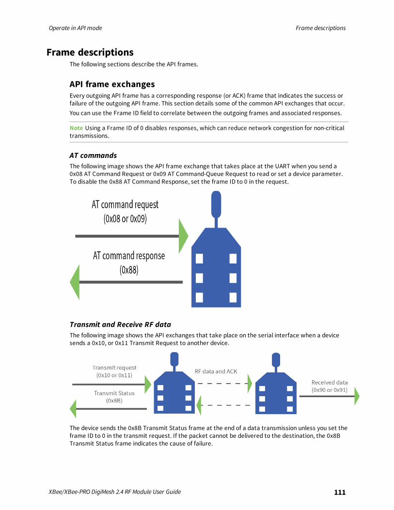
Operate in API mode Frame descriptions
XBee/XBee-PRO DigiMesh 2.4 RF Module User Guide 111
Frame descriptionsThe following sections describe the API frames.
API frame exchangesEvery outgoing API frame has a corresponding response (or ACK) frame that indicates the success orfailure of the outgoing API frame. This section details some of the common API exchanges that occur.You can use the Frame ID field to correlate between the outgoing frames and associated responses.
Note Using a Frame ID of 0 disables responses, which can reduce network congestion for non-criticaltransmissions.
AT commandsThe following image shows the API frame exchange that takes place at the UART when you send a0x08 AT Command Request or 0x09 AT Command-Queue Request to read or set a device parameter.To disable the 0x88 AT Command Response, set the frame ID to 0 in the request.
Transmit and Receive RF dataThe following image shows the API exchanges that take place on the serial interface when a devicesends a 0x10, or 0x11 Transmit Request to another device.
The device sends the 0x8B Transmit Status frame at the end of a data transmission unless you set theframe ID to 0 in the transmit request. If the packet cannot be delivered to the destination, the 0x8BTransmit Status frame indicates the cause of failure.
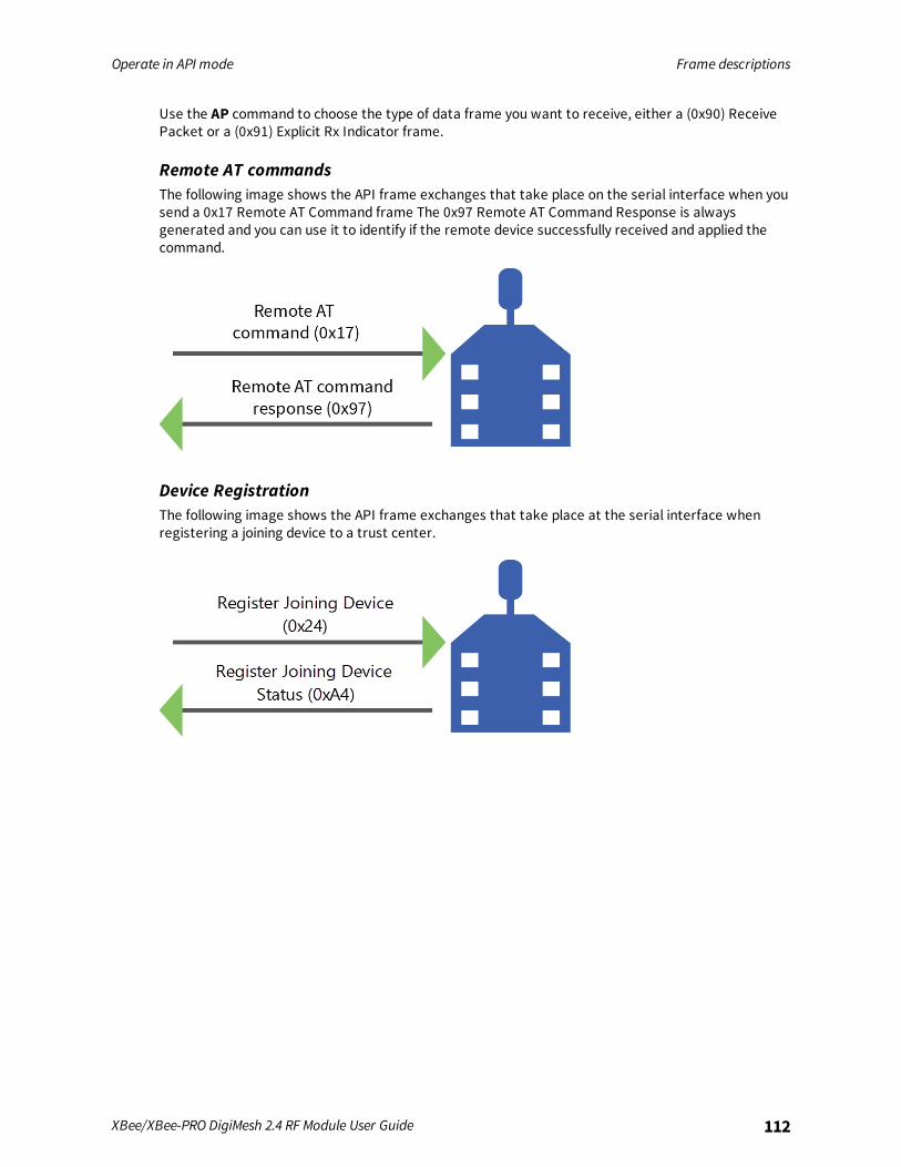
Operate in API mode Frame descriptions
XBee/XBee-PRO DigiMesh 2.4 RF Module User Guide 112
Use the AP command to choose the type of data frame you want to receive, either a (0x90) ReceivePacket or a (0x91) Explicit Rx Indicator frame.
Remote AT commandsThe following image shows the API frame exchanges that take place on the serial interface when yousend a 0x17 Remote AT Command frame The 0x97 Remote AT Command Response is alwaysgenerated and you can use it to identify if the remote device successfully received and applied thecommand.
Device RegistrationThe following image shows the API frame exchanges that take place at the serial interface whenregistering a joining device to a trust center.
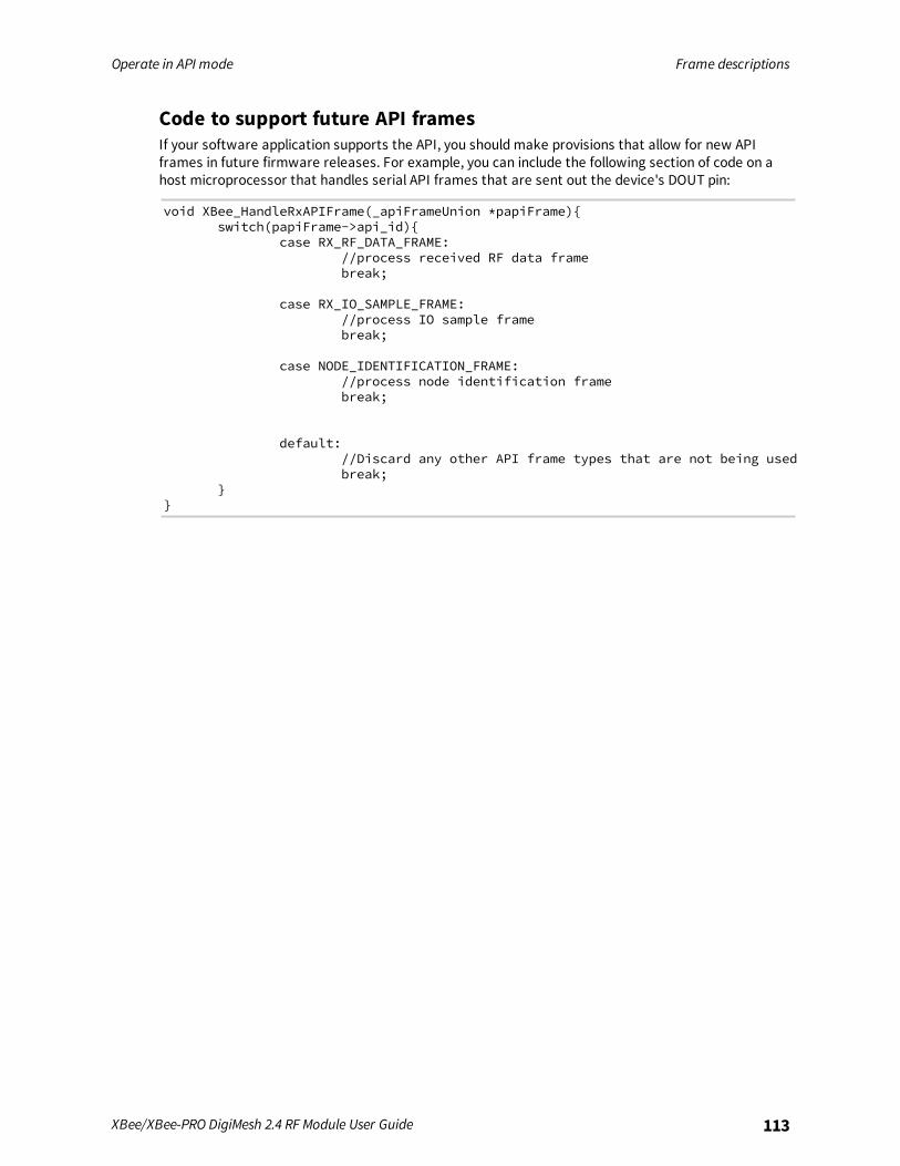
Operate in API mode Frame descriptions
XBee/XBee-PRO DigiMesh 2.4 RF Module User Guide 113
Code to support future API framesIf your software application supports the API, you should make provisions that allow for new APIframes in future firmware releases. For example, you can include the following section of code on ahost microprocessor that handles serial API frames that are sent out the device's DOUT pin:
void XBee_HandleRxAPIFrame(_apiFrameUnion *papiFrame){switch(papiFrame->api_id){
case RX_RF_DATA_FRAME://process received RF data framebreak;
case RX_IO_SAMPLE_FRAME://process IO sample framebreak;
case NODE_IDENTIFICATION_FRAME://process node identification framebreak;
default://Discard any other API frame types that are not being usedbreak;
}}
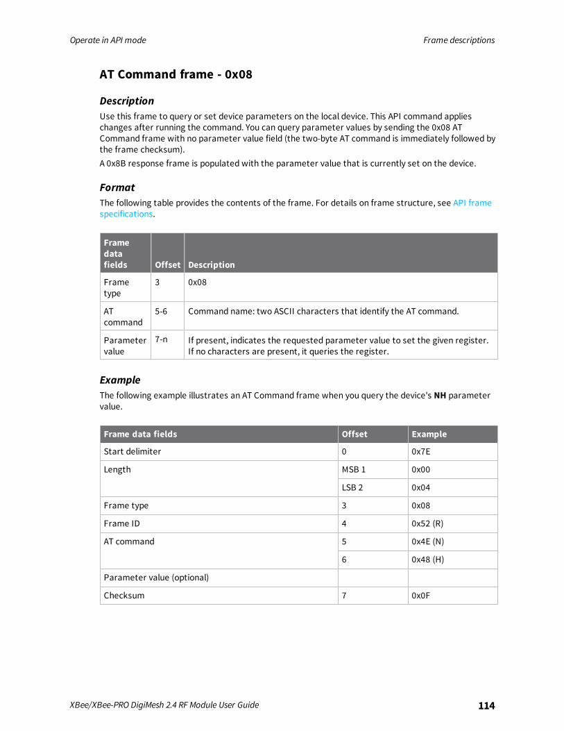
Operate in API mode Frame descriptions
XBee/XBee-PRO DigiMesh 2.4 RF Module User Guide 114
AT Command frame - 0x08
DescriptionUse this frame to query or set device parameters on the local device. This API command applieschanges after running the command. You can query parameter values by sending the 0x08 ATCommand frame with no parameter value field (the two-byte AT command is immediately followed bythe frame checksum).A 0x8B response frame is populated with the parameter value that is currently set on the device.
FormatThe following table provides the contents of the frame. For details on frame structure, see API framespecifications.
Framedatafields Offset Description
Frametype
3 0x08
ATcommand
5-6 Command name: two ASCII characters that identify the AT command.
Parametervalue
7-n If present, indicates the requested parameter value to set the given register.If no characters are present, it queries the register.
ExampleThe following example illustrates an AT Command frame when you query the device's NH parametervalue.
Frame data fields Offset Example
Start delimiter 0 0x7E
Length MSB 1 0x00
LSB 2 0x04
Frame type 3 0x08
Frame ID 4 0x52 (R)
AT command 5 0x4E (N)
6 0x48 (H)
Parameter value (optional)
Checksum 7 0x0F
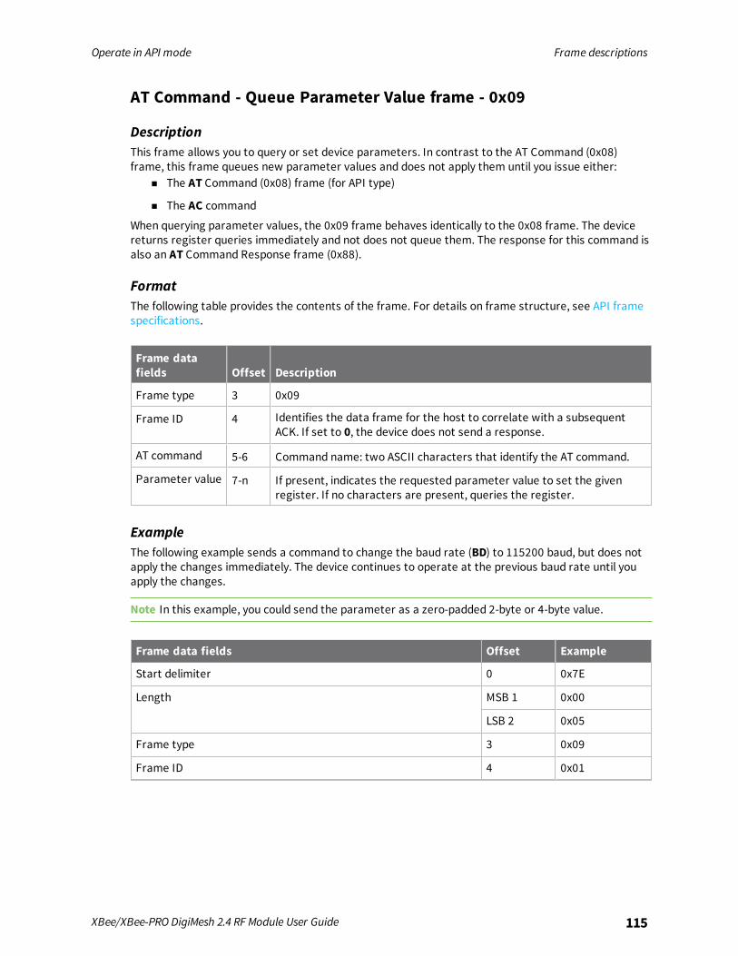
Operate in API mode Frame descriptions
XBee/XBee-PRO DigiMesh 2.4 RF Module User Guide 115
AT Command - Queue Parameter Value frame - 0x09
DescriptionThis frame allows you to query or set device parameters. In contrast to the AT Command (0x08)frame, this frame queues new parameter values and does not apply them until you issue either:
n The AT Command (0x08) frame (for API type)
n The AC command
When querying parameter values, the 0x09 frame behaves identically to the 0x08 frame. The devicereturns register queries immediately and not does not queue them. The response for this command isalso an AT Command Response frame (0x88).
FormatThe following table provides the contents of the frame. For details on frame structure, see API framespecifications.
Frame datafields Offset Description
Frame type 3 0x09
Frame ID 4 Identifies the data frame for the host to correlate with a subsequentACK. If set to 0, the device does not send a response.
AT command 5-6 Command name: two ASCII characters that identify the AT command.
Parameter value 7-n If present, indicates the requested parameter value to set the givenregister. If no characters are present, queries the register.
ExampleThe following example sends a command to change the baud rate (BD) to 115200 baud, but does notapply the changes immediately. The device continues to operate at the previous baud rate until youapply the changes.
Note In this example, you could send the parameter as a zero-padded 2-byte or 4-byte value.
Frame data fields Offset Example
Start delimiter 0 0x7E
Length MSB 1 0x00
LSB 2 0x05
Frame type 3 0x09
Frame ID 4 0x01

Operate in API mode Frame descriptions
XBee/XBee-PRO DigiMesh 2.4 RF Module User Guide 116
Frame data fields Offset Example
AT command 5 0x42 (B)
6 0x44 (D)
Parameter value (BD7 = 115200 baud) 7 0x07
Checksum 8 0x68

Operate in API mode Frame descriptions
XBee/XBee-PRO DigiMesh 2.4 RF Module User Guide 117
Transmit Request frame - 0x10
DescriptionThis frame causes the device to send payload data as an RF packet to a specific destination.
n For broadcast transmissions, set the 64-bit destination address to 0x000000000000FFFF .
n For unicast transmissions, set the 64 bit address field to the address of the desired destinationnode.
n Set the reserved field to 0xFFFE.
n Query the NP command to read the maximum number of payload bytes.
You can set the broadcast radius from 0 up to NH. If set to 0, the value of NH specifies the broadcastradius (recommended). This parameter is only used for broadcast transmissions.You can read the maximum number of payload bytes with the NP command.
Note Using source routing reduces the RF payload by two bytes per intermediate hop in the sourceroute.
FormatThe following table provides the contents of the frame. For details on the frame structure, see APIframe specifications.
Framedatafields Offset Description
Frametype
3 0x10
Frame ID 4 Identifies the data frame for the host to correlate with a subsequent ACK. Ifset to 0, the device does not send a response.
64-bitdestinationaddress
5-12 MSB first, LSB last. Set to the 64-bit address of the destination device.Broadcast = 0x000000000000FFFF
Reserved 13-14 Set to 0xFFFE.
Broadcastradius
15 Sets the maximum number of hops a broadcast transmission can occur. If setto 0, the broadcast radius is set to the maximum hops value.
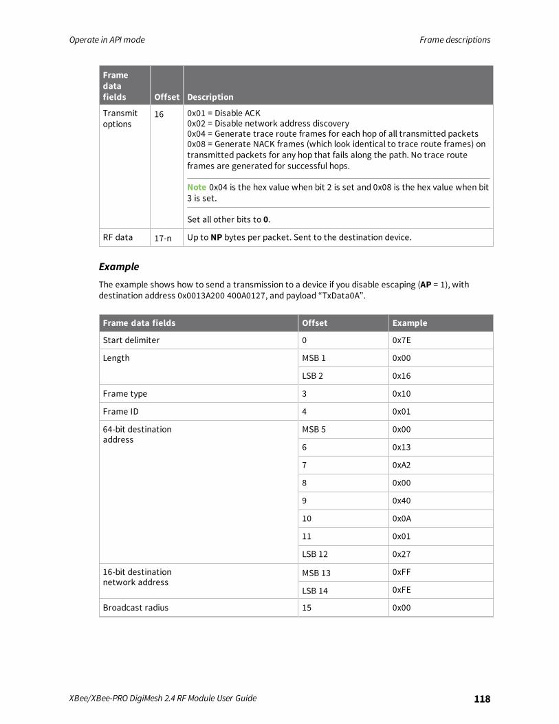
Operate in API mode Frame descriptions
XBee/XBee-PRO DigiMesh 2.4 RF Module User Guide 118
Framedatafields Offset Description
Transmitoptions
16 0x01 = Disable ACK0x02 = Disable network address discovery0x04 = Generate trace route frames for each hop of all transmitted packets0x08 = Generate NACK frames (which look identical to trace route frames) ontransmitted packets for any hop that fails along the path. No trace routeframes are generated for successful hops.
Note 0x04 is the hex value when bit 2 is set and 0x08 is the hex value when bit3 is set.
Set all other bits to 0.
RF data 17-n Up to NP bytes per packet. Sent to the destination device.
Example
The example shows how to send a transmission to a device if you disable escaping (AP = 1), withdestination address 0x0013A200 400A0127, and payload “TxData0A”.
Frame data fields Offset Example
Start delimiter 0 0x7E
Length MSB 1 0x00
LSB 2 0x16
Frame type 3 0x10
Frame ID 4 0x01
64-bit destinationaddress
MSB 5 0x00
6 0x13
7 0xA2
8 0x00
9 0x40
10 0x0A
11 0x01
LSB 12 0x27
16-bit destinationnetwork address
MSB 13 0xFF
LSB 14 0xFE
Broadcast radius 15 0x00
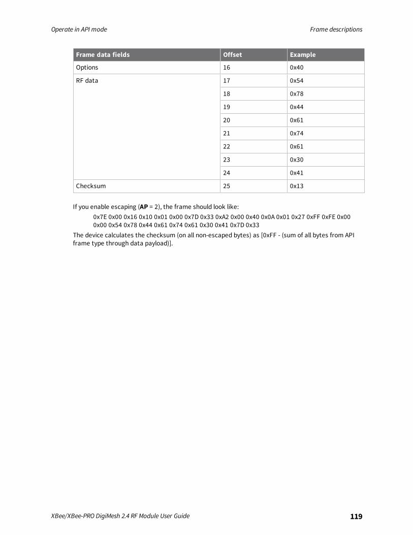
Operate in API mode Frame descriptions
XBee/XBee-PRO DigiMesh 2.4 RF Module User Guide 119
Frame data fields Offset Example
Options 16 0x40
RF data 17 0x54
18 0x78
19 0x44
20 0x61
21 0x74
22 0x61
23 0x30
24 0x41
Checksum 25 0x13
If you enable escaping (AP = 2), the frame should look like:0x7E 0x00 0x16 0x10 0x01 0x00 0x7D 0x33 0xA2 0x00 0x40 0x0A 0x01 0x27 0xFF 0xFE 0x000x00 0x54 0x78 0x44 0x61 0x74 0x61 0x30 0x41 0x7D 0x33
The device calculates the checksum (on all non-escaped bytes) as [0xFF - (sum of all bytes from APIframe type through data payload)].
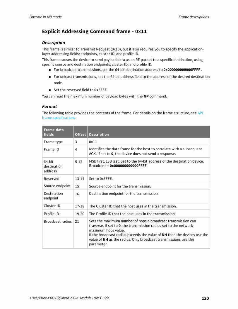
Operate in API mode Frame descriptions
XBee/XBee-PRO DigiMesh 2.4 RF Module User Guide 120
Explicit Addressing Command frame - 0x11
DescriptionThis frame is similar to Transmit Request (0x10), but it also requires you to specify the application-layer addressing fields: endpoints, cluster ID, and profile ID.This frame causes the device to send payload data as an RF packet to a specific destination, usingspecific source and destination endpoints, cluster ID, and profile ID.
n For broadcast transmissions, set the 64-bit destination address to 0x000000000000FFFF .
n For unicast transmissions, set the 64 bit address field to the address of the desired destinationnode.
n Set the reserved field to 0xFFFE.You can read the maximum number of payload bytes with the NP command.
FormatThe following table provides the contents of the frame. For details on the frame structure, see APIframe specifications.
Frame datafields Offset Description
Frame type 3 0x11
Frame ID 4 Identifies the data frame for the host to correlate with a subsequentACK. If set to 0, the device does not send a response.
64-bitdestinationaddress
5-12 MSB first, LSB last. Set to the 64-bit address of the destination device.Broadcast = 0x000000000000FFFF
Reserved 13-14 Set to 0xFFFE.
Source endpoint 15 Source endpoint for the transmission.
Destinationendpoint
16 Destination endpoint for the transmission.
Cluster ID 17-18 The Cluster ID that the host uses in the transmission.
Profile ID 19-20 The Profile ID that the host uses in the transmission.
Broadcast radius 21 Sets the maximum number of hops a broadcast transmission cantraverse. If set to 0, the transmission radius set to the networkmaximum hops value.If the broadcast radius exceeds the value of NH then the devices use thevalue of NH as the radius. Only broadcast transmissions use thisparameter.
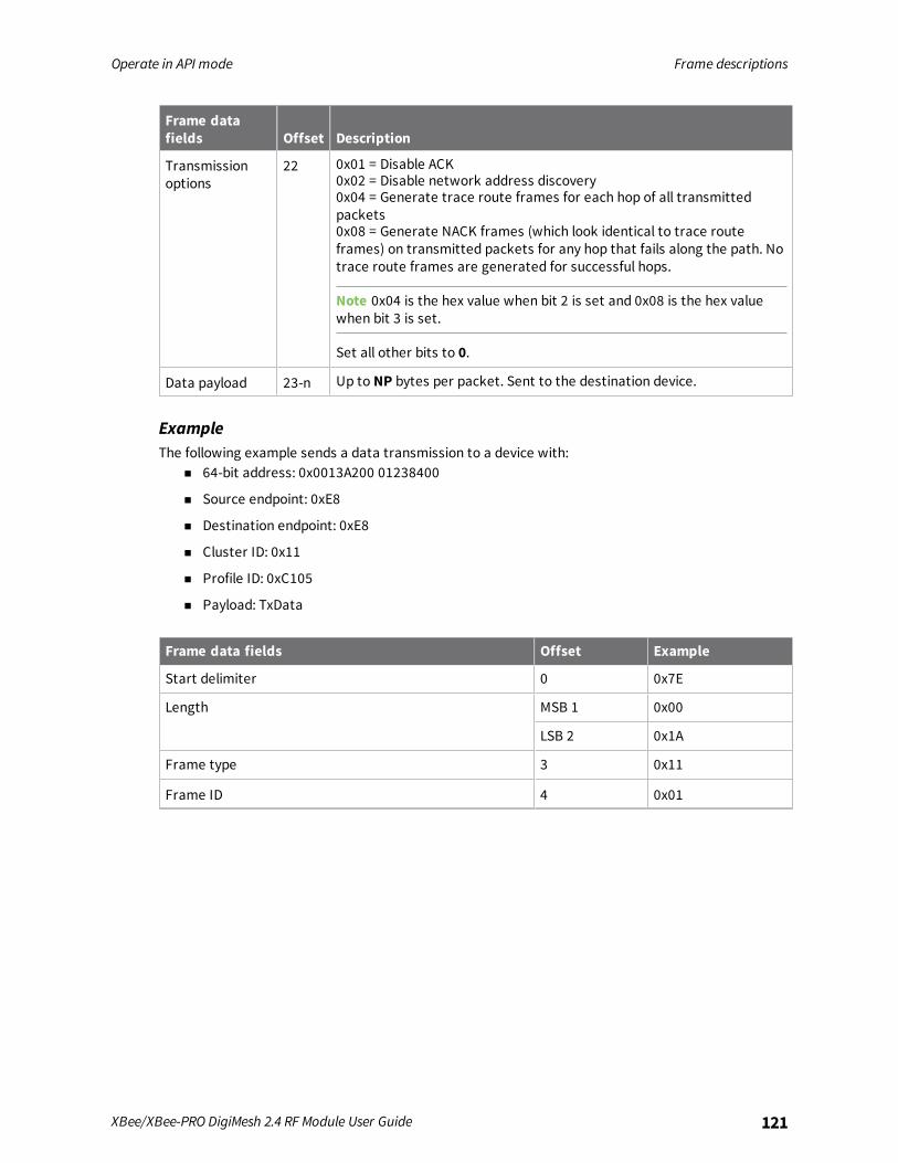
Operate in API mode Frame descriptions
XBee/XBee-PRO DigiMesh 2.4 RF Module User Guide 121
Frame datafields Offset Description
Transmissionoptions
22 0x01 = Disable ACK0x02 = Disable network address discovery0x04 = Generate trace route frames for each hop of all transmittedpackets0x08 = Generate NACK frames (which look identical to trace routeframes) on transmitted packets for any hop that fails along the path. Notrace route frames are generated for successful hops.
Note 0x04 is the hex value when bit 2 is set and 0x08 is the hex valuewhen bit 3 is set.
Set all other bits to 0.
Data payload 23-n Up to NP bytes per packet. Sent to the destination device.
ExampleThe following example sends a data transmission to a device with:
n 64-bit address: 0x0013A200 01238400
n Source endpoint: 0xE8
n Destination endpoint: 0xE8
n Cluster ID: 0x11
n Profile ID: 0xC105
n Payload: TxData
Frame data fields Offset Example
Start delimiter 0 0x7E
Length MSB 1 0x00
LSB 2 0x1A
Frame type 3 0x11
Frame ID 4 0x01

Operate in API mode Frame descriptions
XBee/XBee-PRO DigiMesh 2.4 RF Module User Guide 122
Frame data fields Offset Example
64-bit destination address MSB 5 0x00
6 0x13
7 0xA2
8 0x00
9 0x01
10 0x23
11 0x84
LSB12 0x00
Reserved 13 0xFF
14 0xFE
Source endpoint 15 0xE8
Destination endpoint 16 0xE8
Cluster ID 17 0x00
18 0x11
Profile ID 19 0xC1
20 0x05
Broadcast radius 21 0x00
Transmit options 22 0x00
Data payload 23 0x54
24 0x78
25 0x44
26 0x61
27 0x74
28 0x61
Checksum 29 0xA6
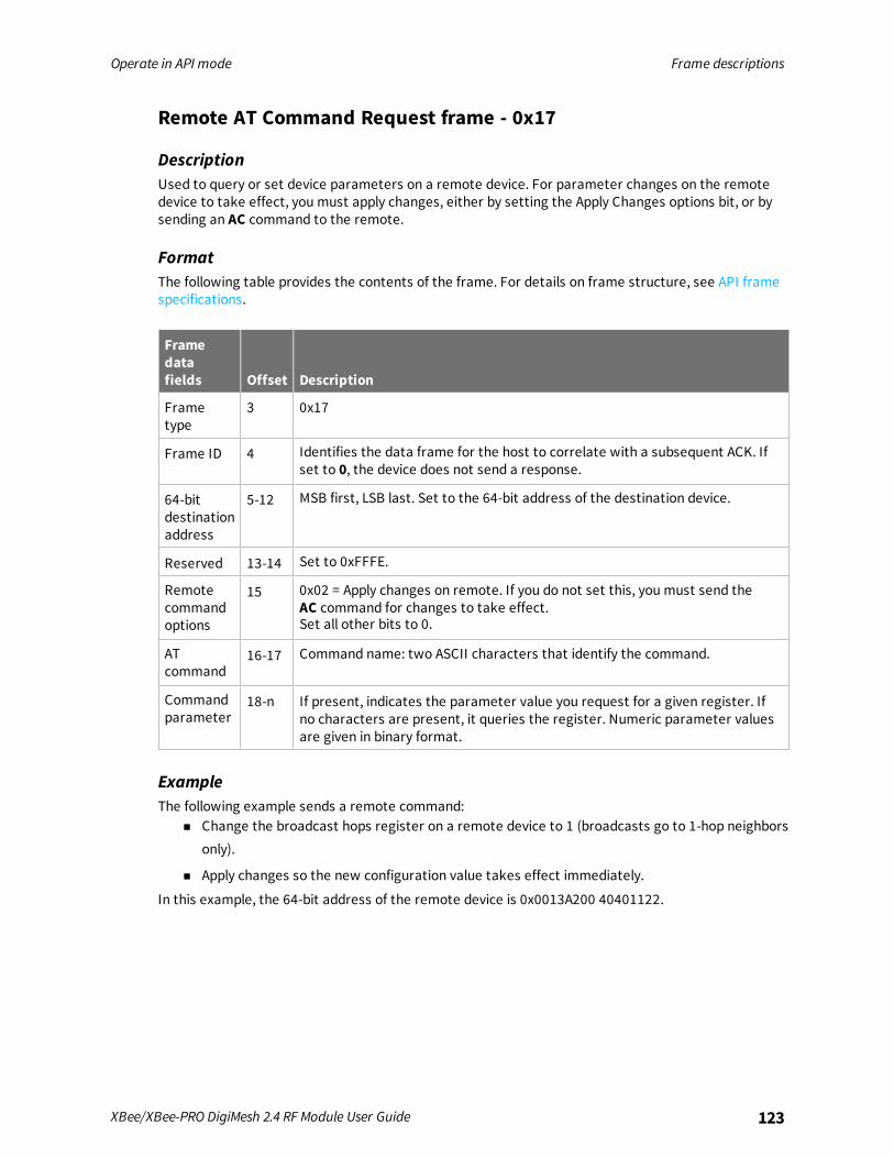
Operate in API mode Frame descriptions
XBee/XBee-PRO DigiMesh 2.4 RF Module User Guide 123
Remote AT Command Request frame - 0x17
DescriptionUsed to query or set device parameters on a remote device. For parameter changes on the remotedevice to take effect, you must apply changes, either by setting the Apply Changes options bit, or bysending an AC command to the remote.
FormatThe following table provides the contents of the frame. For details on frame structure, see API framespecifications.
Framedatafields Offset Description
Frametype
3 0x17
Frame ID 4 Identifies the data frame for the host to correlate with a subsequent ACK. Ifset to 0, the device does not send a response.
64-bitdestinationaddress
5-12 MSB first, LSB last. Set to the 64-bit address of the destination device.
Reserved 13-14 Set to 0xFFFE.
Remotecommandoptions
15 0x02 = Apply changes on remote. If you do not set this, you must send theAC command for changes to take effect.Set all other bits to 0.
ATcommand
16-17 Command name: two ASCII characters that identify the command.
Commandparameter
18-n If present, indicates the parameter value you request for a given register. Ifno characters are present, it queries the register. Numeric parameter valuesare given in binary format.
ExampleThe following example sends a remote command:
n Change the broadcast hops register on a remote device to 1 (broadcasts go to 1-hop neighborsonly).
n Apply changes so the new configuration value takes effect immediately.
In this example, the 64-bit address of the remote device is 0x0013A200 40401122.
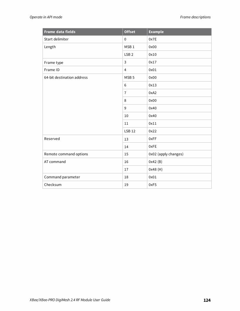
Operate in API mode Frame descriptions
XBee/XBee-PRO DigiMesh 2.4 RF Module User Guide 124
Frame data fields Offset Example
Start delimiter 0 0x7E
Length MSB 1 0x00
LSB 2 0x10
Frame type 3 0x17
Frame ID 4 0x01
64-bit destination address MSB 5 0x00
6 0x13
7 0xA2
8 0x00
9 0x40
10 0x40
11 0x11
LSB 12 0x22
Reserved 13 0xFF
14 0xFE
Remote command options 15 0x02 (apply changes)
AT command 16 0x42 (B)
17 0x48 (H)
Command parameter 18 0x01
Checksum 19 0xF5

Operate in API mode Frame descriptions
XBee/XBee-PRO DigiMesh 2.4 RF Module User Guide 125
AT Command Response frame - 0x88
DescriptionA device sends this frame in response to an AT Command (0x08 or 0x09) frame. Some commands sendback multiple frames; for example, the ND command.
Format
Frame datafields Offset Description
Frame type 3 0x88
Frame ID 4 Identifies the data frame for the host to correlate with a subsequent ACK. Ifset to 0, the device does not send a response.
ATcommand
5-6 Command name: two ASCII characters that identify the command.
Commandstatus
7 0 = OK1 = ERROR2 = Invalid command3 = Invalid parameter
Commanddata
8-n The register data in binary format. If the host sets the register, the devicedoes not return this field.
ExampleIf you change the BD parameter on a local device with a frame ID of 0x01, and the parameter is valid,the user receives the following response.
Frame datafields Offset Example
Start delimiter 0 0x7E
Length MSB 1 0x00
LSB 2 0x05
Frame type 3 0x88
Frame ID 4 0x01
AT command 5 0x42 (B)
6 0x44 (D)
Command status 7 0x00
Command data (No command data implies the parameter was set rather thanqueried)
Checksum 8 0xF0

Operate in API mode Frame descriptions
XBee/XBee-PRO DigiMesh 2.4 RF Module User Guide 126
Modem Status frame - 0x8A
DescriptionDevices send the status messages in this frame in response to specific conditions.
FormatThe following table provides the contents of the frame. For details on frame structure, see API framespecifications.
Frame data fields Offset Description
Frame type 3 0x8A
Status 4 0x00 = Hardware reset0x01 = Watchdog timer reset0x0B = Network woke up0x0C = Network went to sleep
ExampleWhen a device powers up, it returns the following API frame.
Frame data fields Offset Example
Start delimiter 0 0x7E
Length MSB 1 0x00
LSB 2 LSB 2 0x02
Frame type 3 0x8A
Status 4 0x00
Checksum 5 0x75
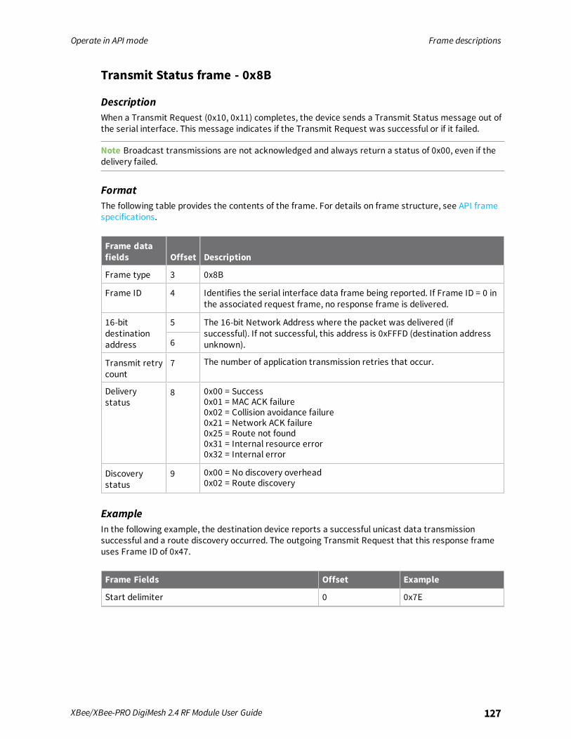
Operate in API mode Frame descriptions
XBee/XBee-PRO DigiMesh 2.4 RF Module User Guide 127
Transmit Status frame - 0x8B
DescriptionWhen a Transmit Request (0x10, 0x11) completes, the device sends a Transmit Status message out ofthe serial interface. This message indicates if the Transmit Request was successful or if it failed.
Note Broadcast transmissions are not acknowledged and always return a status of 0x00, even if thedelivery failed.
FormatThe following table provides the contents of the frame. For details on frame structure, see API framespecifications.
Frame datafields Offset Description
Frame type 3 0x8B
Frame ID 4 Identifies the serial interface data frame being reported. If Frame ID = 0 inthe associated request frame, no response frame is delivered.
16-bitdestinationaddress
5 The 16-bit Network Address where the packet was delivered (ifsuccessful). If not successful, this address is 0xFFFD (destination addressunknown).6
Transmit retrycount
7 The number of application transmission retries that occur.
Deliverystatus
8 0x00 = Success0x01 = MAC ACK failure0x02 = Collision avoidance failure0x21 = Network ACK failure0x25 = Route not found0x31 = Internal resource error0x32 = Internal error
Discoverystatus
9 0x00 = No discovery overhead0x02 = Route discovery
ExampleIn the following example, the destination device reports a successful unicast data transmissionsuccessful and a route discovery occurred. The outgoing Transmit Request that this response frameuses Frame ID of 0x47.
Frame Fields Offset Example
Start delimiter 0 0x7E
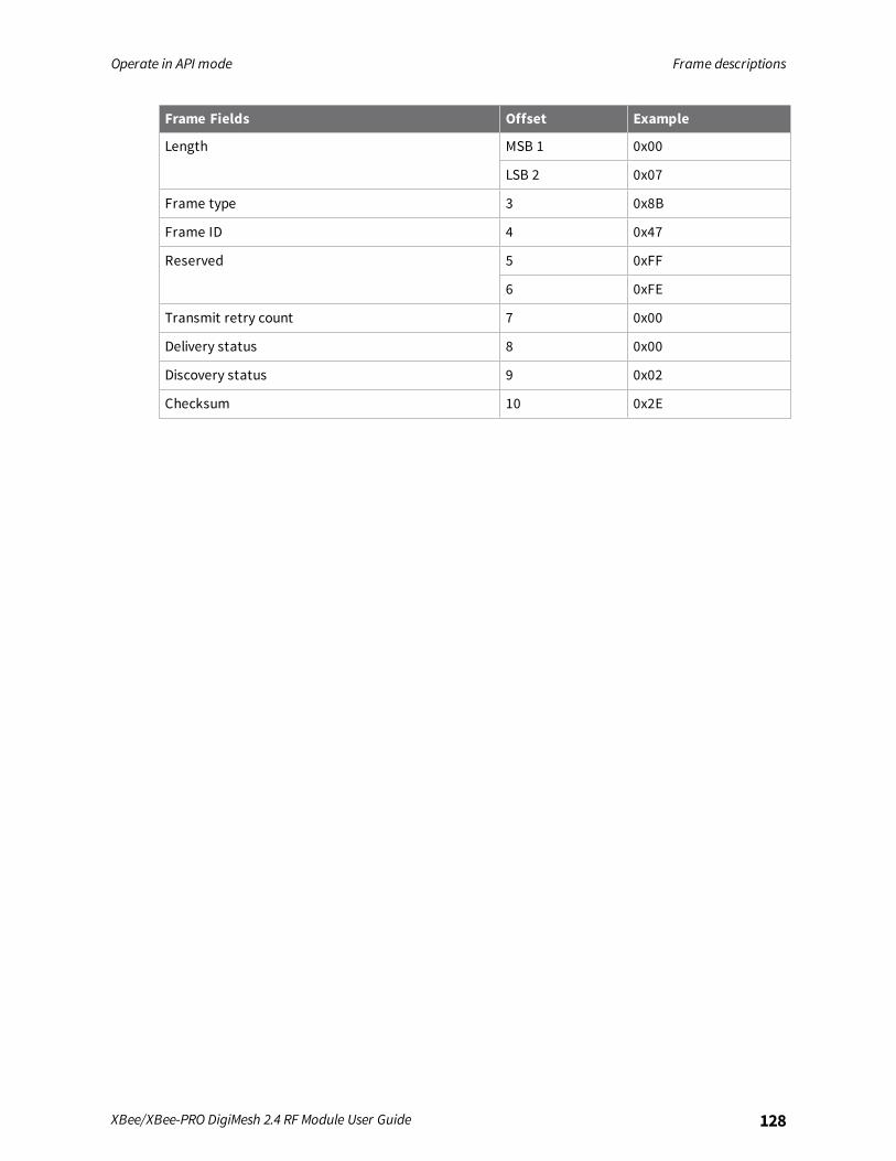
Operate in API mode Frame descriptions
XBee/XBee-PRO DigiMesh 2.4 RF Module User Guide 128
Frame Fields Offset Example
Length MSB 1 0x00
LSB 2 0x07
Frame type 3 0x8B
Frame ID 4 0x47
Reserved 5 0xFF
6 0xFE
Transmit retry count 7 0x00
Delivery status 8 0x00
Discovery status 9 0x02
Checksum 10 0x2E

Operate in API mode Frame descriptions
XBee/XBee-PRO DigiMesh 2.4 RF Module User Guide 129
Route Information Packet frame - 0x8D
DescriptionIf you enable NACK or the Trace Route option on a DigiMesh unicast transmission, a device can outputthis frame for the transmission.
FormatThe following table provides the contents of the frame. For details on frame structure, see API framespecifications.
Frame data fields Offset Description
Frame type 3 0x8D
Source event 4 0x11 = NACK0x12 = Trace route
Length 5 The number of bytes that follow, excluding the checksum. If thelength increases, new items have been added to the end of the listfor future revisions.
Timestamp 6-9 System timer value on the node generating the Route InformationPacket. The timestamp is in microseconds. Only use this value forrelative time measurements because the time stamp count restartsapproximately every hour.
ACK timeout count 10 The number of MAC ACK timeouts that occur.
TX blocked count 11 The number of times the transmission was blocked due to receptionin progress.
Reserved 12 Reserved, set to 0s.
Destination address 13-20 The address of the final destination node of this network-leveltransmission.
Source address 21-28 Address of the source node of this network-level transmission.
Responder address 29-36 Address of the node that generates this Route Information packetafter it sends (or attempts to send) the packet to the next hop (theReceiver node).
Receiver address 37-44 Address of the node that the device sends (or attempts to send) thedata packet.
ExampleThe following example represents a possible Route Information Packet. A device receives the packetwhen it performs a trace route on a transmission from one device (serial number 0x0013A2004052AAAA) to another (serial number 0x0013A200 4052DDDD).This particular frame indicates that the network successfully forwards the transmission from onedevice (serial number 0x0013A200 4052BBBB) to another device (serial number 0x0013A2004052CCCC).

Operate in API mode Frame descriptions
XBee/XBee-PRO DigiMesh 2.4 RF Module User Guide 130
Frame data fields Offset Example
Start delimiter 0 0x7E
Length MSB 1 0x00
LSB 2 0x2A
Frame type 3 0x8D
Source event 4 0x12
Length 5 0x27
Timestamp MSB 6 0x9C
7 0x93
8 0x81
LSB 9 0x7F
ACK timeout count 10 0x00
TX blocked count 11 0x00
Reserved 12 0x00
Destination address MSB 13 0x00
14 0x13
15 0xA2
16 0x00
17 0x40
18 0x52
19 0xAA
LSB 20 0xAA
Source address MSB 21 0x00
22 0x13
23 0xA2
24 0x00
25 0x40
26 0x52
27 0xDD
LSB 28 0xDD
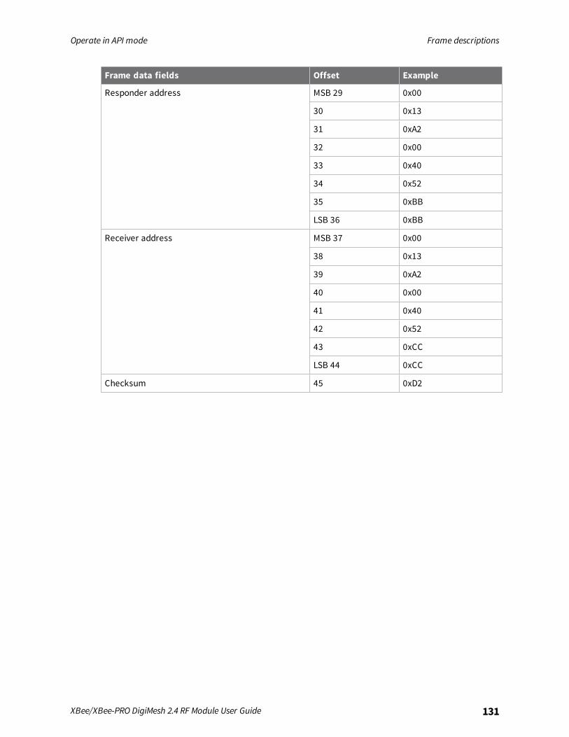
Operate in API mode Frame descriptions
XBee/XBee-PRO DigiMesh 2.4 RF Module User Guide 131
Frame data fields Offset Example
Responder address MSB 29 0x00
30 0x13
31 0xA2
32 0x00
33 0x40
34 0x52
35 0xBB
LSB 36 0xBB
Receiver address MSB 37 0x00
38 0x13
39 0xA2
40 0x00
41 0x40
42 0x52
43 0xCC
LSB 44 0xCC
Checksum 45 0xD2
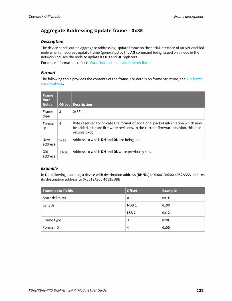
Operate in API mode Frame descriptions
XBee/XBee-PRO DigiMesh 2.4 RF Module User Guide 132
Aggregate Addressing Update frame - 0x8E
DescriptionThe device sends out an Aggregate Addressing Update frame on the serial interface of an API-enablednode when an address update frame (generated by the AG command being issued on a node in thenetwork) causes the node to update its DH and DL registers.For more information, refer to Establish andmaintain network links.
FormatThe following table provides the contents of the frame. For details on frame structure, see API framespecifications.
Framedatafields Offset Description
Frametype
3 0x8E
FormatID
4 Byte reserved to indicate the format of additional packet information which maybe added in future firmware revisions. In the current firmware revision, this fieldreturns 0x00.
Newaddress
5-12 Address to which DH and DL are being set.
Oldaddress
13-20 Address to which DH and DL were previously set.
ExampleIn the following example, a device with destination address (DH/DL) of 0x0013A200 4052AAAA updatesits destination address to 0x0013A200 4052BBBB.
Frame data fields Offset Example
Start delimiter 0 0x7E
Length MSB 1 0x00
LSB 2 0x12
Frame type 3 0x8E
Format ID 4 0x00
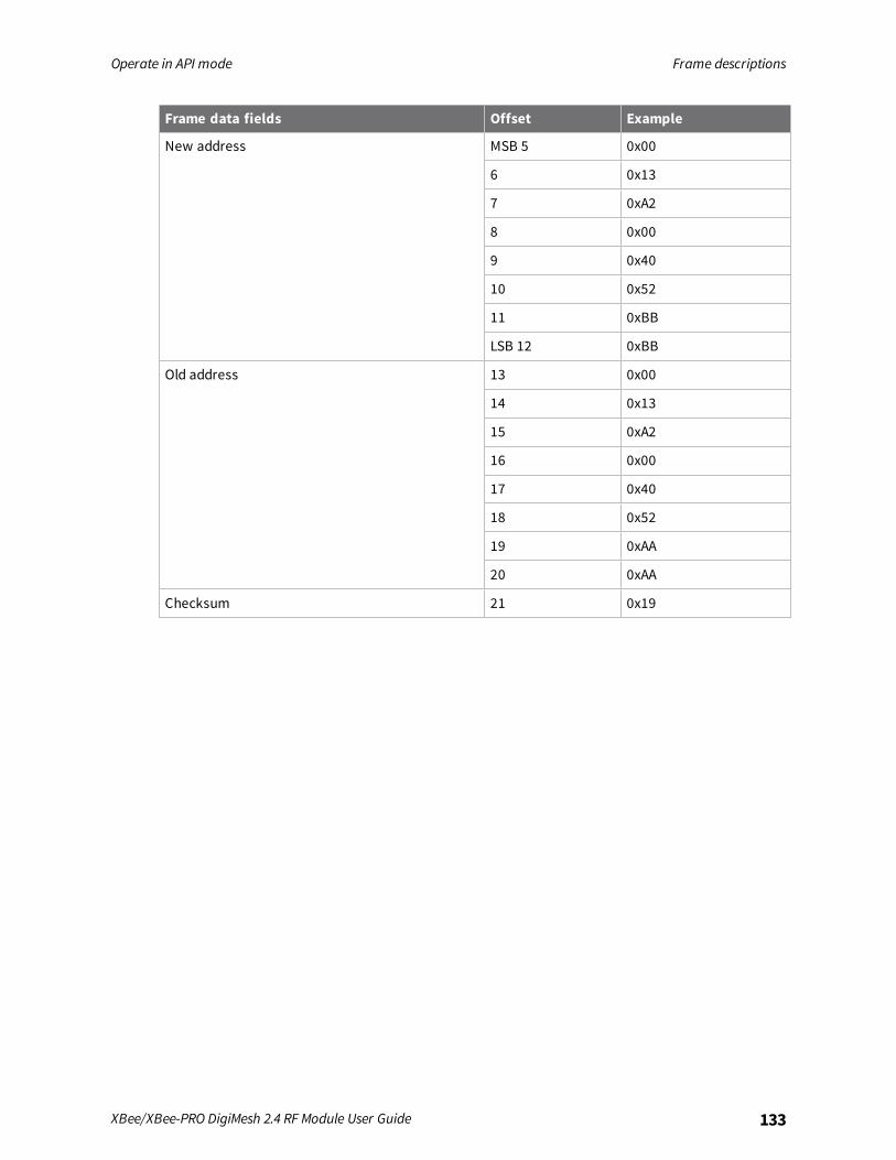
Operate in API mode Frame descriptions
XBee/XBee-PRO DigiMesh 2.4 RF Module User Guide 133
Frame data fields Offset Example
New address MSB 5 0x00
6 0x13
7 0xA2
8 0x00
9 0x40
10 0x52
11 0xBB
LSB 12 0xBB
Old address 13 0x00
14 0x13
15 0xA2
16 0x00
17 0x40
18 0x52
19 0xAA
20 0xAA
Checksum 21 0x19
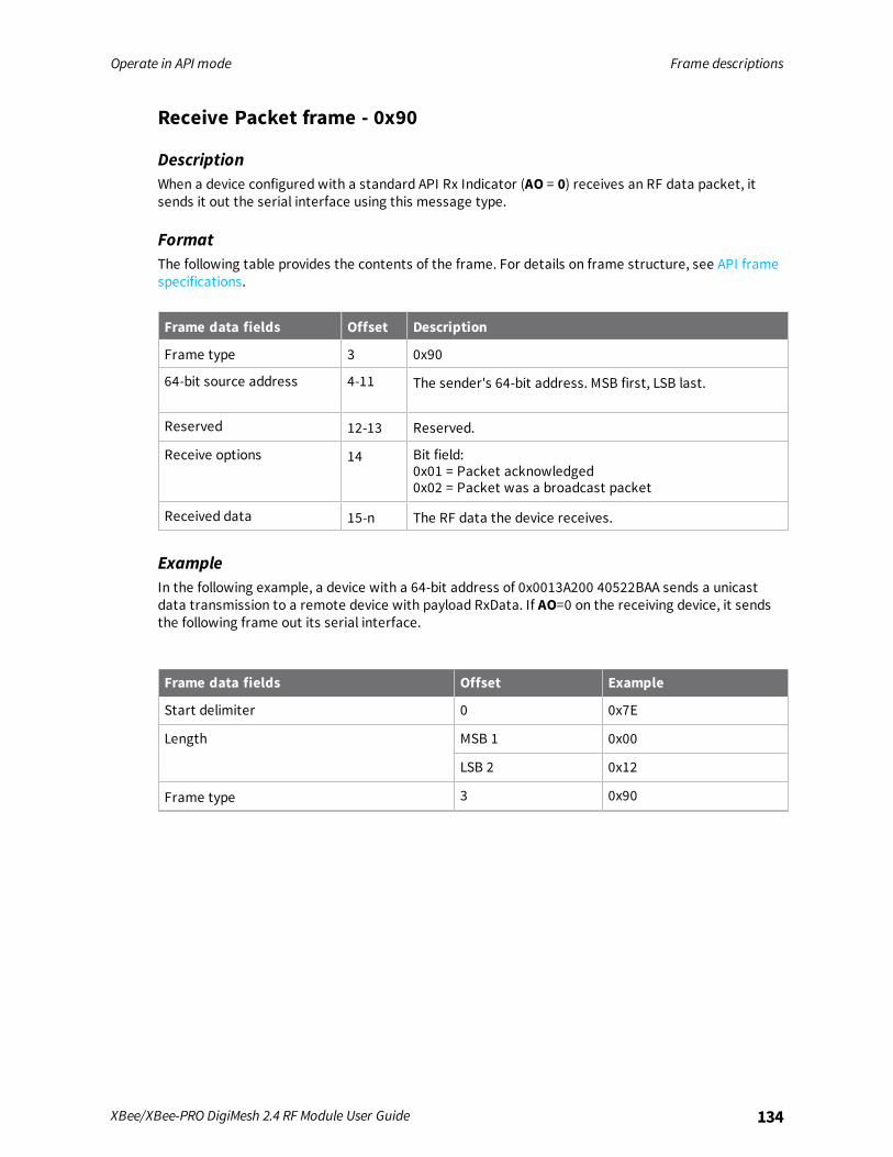
Operate in API mode Frame descriptions
XBee/XBee-PRO DigiMesh 2.4 RF Module User Guide 134
Receive Packet frame - 0x90
DescriptionWhen a device configured with a standard API Rx Indicator (AO = 0) receives an RF data packet, itsends it out the serial interface using this message type.
FormatThe following table provides the contents of the frame. For details on frame structure, see API framespecifications.
Frame data fields Offset Description
Frame type 3 0x90
64-bit source address 4-11 The sender's 64-bit address. MSB first, LSB last.
Reserved 12-13 Reserved.
Receive options 14 Bit field:0x01 = Packet acknowledged0x02 = Packet was a broadcast packet
Received data 15-n The RF data the device receives.
ExampleIn the following example, a device with a 64-bit address of 0x0013A200 40522BAA sends a unicastdata transmission to a remote device with payload RxData. If AO=0 on the receiving device, it sendsthe following frame out its serial interface.
Frame data fields Offset Example
Start delimiter 0 0x7E
Length MSB 1 0x00
LSB 2 0x12
Frame type 3 0x90
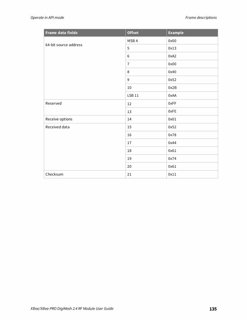
Operate in API mode Frame descriptions
XBee/XBee-PRO DigiMesh 2.4 RF Module User Guide 135
Frame data fields Offset Example
64-bit source addressMSB 4 0x00
5 0x13
6 0xA2
7 0x00
8 0x40
9 0x52
10 0x2B
LSB 11 0xAA
Reserved 12 0xFF
13 0xFE
Receive options 14 0x01
Received data 15 0x52
16 0x78
17 0x44
18 0x61
19 0x74
20 0x61
Checksum 21 0x11

Operate in API mode Frame descriptions
XBee/XBee-PRO DigiMesh 2.4 RF Module User Guide 136
Explicit Rx Indicator frame - 0x91
DescriptionWhen a device configured with explicit API Rx Indicator (AO = 1) receives an RF packet, it sends it outthe serial interface using this message type.
Note If a Transmit Request frame - 0x10 is sent to a device with AO = 1, the receiving device receivesa 0x91 frame with the Source endpoint (SE), Destination endpoint (DE), and Cluster ID (CI) that wereset on the transmitting device in Transparent mode, and not the default values.
The Cluster ID and endpoints must be used to identify the type of transaction that occurred.
FormatThe following table provides the contents of the frame. For details on frame structure, see API framespecifications.
Frame data fields Offset Description
Frame type 3 0x91
64-bit source address 4-11 MSB first, LSB last. The sender's 64-bit address.
Reserved 12-13 Reserved.
Source endpoint 14 Endpoint of the source that initiates transmission.
Destination endpoint 15 Endpoint of the destination where the message is addressed.
Cluster ID 16-17 The Cluster ID where the frame is addressed.
Profile ID 18-19 The Profile ID where the fame is addressed.
Receive options 20 Bit field:0x01 = Packet acknowledged0x02 = Packet was a broadcast packetIgnore all other bits.
Received data 21-n Received RF data.
ExampleIn the following example, a device with a 64-bit address of 0x0013A200 40522BAA sends a broadcastdata transmission to a remote device with payload RxData.If a device sends the transmission:
n With source and destination endpoints of 0xE0
n Cluster ID = 0x2211
n Profile ID = 0xC105
If AO = 1 on the receiving device, it sends the following frame out its serial interface.
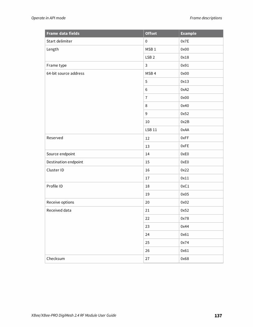
Operate in API mode Frame descriptions
XBee/XBee-PRO DigiMesh 2.4 RF Module User Guide 137
Frame data fields Offset Example
Start delimiter 0 0x7E
Length MSB 1 0x00
LSB 2 0x18
Frame type 3 0x91
64-bit source address MSB 4 0x00
5 0x13
6 0xA2
7 0x00
8 0x40
9 0x52
10 0x2B
LSB 11 0xAA
Reserved 12 0xFF
13 0xFE
Source endpoint 14 0xE0
Destination endpoint 15 0xE0
Cluster ID 16 0x22
17 0x11
Profile ID 18 0xC1
19 0x05
Receive options 20 0x02
Received data 21 0x52
22 0x78
23 0x44
24 0x61
25 0x74
26 0x61
Checksum 27 0x68
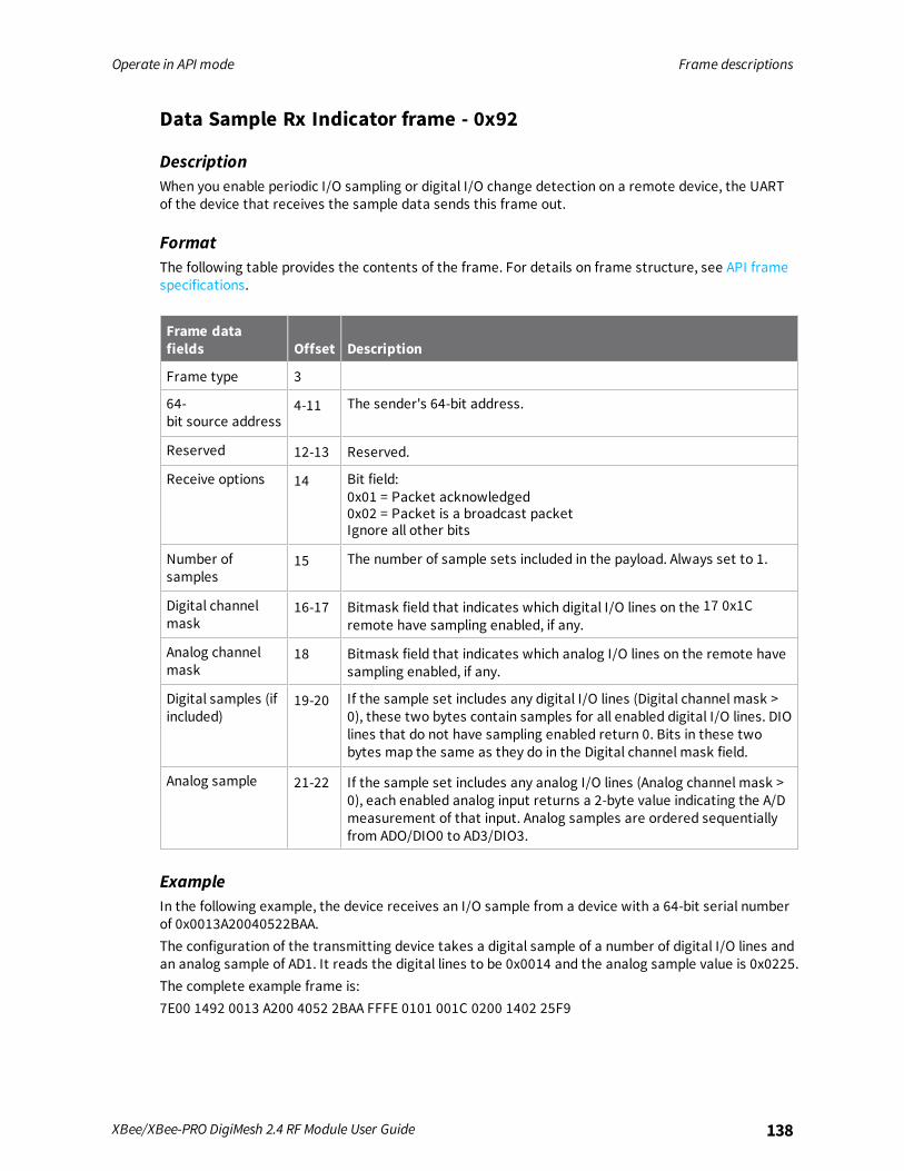
Operate in API mode Frame descriptions
XBee/XBee-PRO DigiMesh 2.4 RF Module User Guide 138
Data Sample Rx Indicator frame - 0x92
DescriptionWhen you enable periodic I/O sampling or digital I/O change detection on a remote device, the UARTof the device that receives the sample data sends this frame out.
FormatThe following table provides the contents of the frame. For details on frame structure, see API framespecifications.
Frame datafields Offset Description
Frame type 3
64-bit source address
4-11 The sender's 64-bit address.
Reserved 12-13 Reserved.
Receive options 14 Bit field:0x01 = Packet acknowledged0x02 = Packet is a broadcast packetIgnore all other bits
Number ofsamples
15 The number of sample sets included in the payload. Always set to 1.
Digital channelmask
16-17 Bitmask field that indicates which digital I/O lines on the 17 0x1Cremote have sampling enabled, if any.
Analog channelmask
18 Bitmask field that indicates which analog I/O lines on the remote havesampling enabled, if any.
Digital samples (ifincluded)
19-20 If the sample set includes any digital I/O lines (Digital channel mask >0), these two bytes contain samples for all enabled digital I/O lines. DIOlines that do not have sampling enabled return 0. Bits in these twobytes map the same as they do in the Digital channel mask field.
Analog sample 21-22 If the sample set includes any analog I/O lines (Analog channel mask >0), each enabled analog input returns a 2-byte value indicating the A/Dmeasurement of that input. Analog samples are ordered sequentiallyfrom ADO/DIO0 to AD3/DIO3.
ExampleIn the following example, the device receives an I/O sample from a device with a 64-bit serial numberof 0x0013A20040522BAA.The configuration of the transmitting device takes a digital sample of a number of digital I/O lines andan analog sample of AD1. It reads the digital lines to be 0x0014 and the analog sample value is 0x0225.The complete example frame is:7E00 1492 0013 A200 4052 2BAA FFFE 0101 001C 0200 1402 25F9
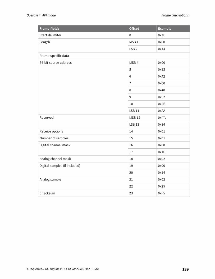
Operate in API mode Frame descriptions
XBee/XBee-PRO DigiMesh 2.4 RF Module User Guide 139
Frame fields Offset Example
Start delimiter 0 0x7E
Length MSB 1 0x00
LSB 2 0x14
Frame-specific data
64-bit source address MSB 4 0x00
5 0x13
6 0xA2
7 0x00
8 0x40
9 0x52
10 0x2B
LSB 11 0xAA
Reserved MSB 12 0xfffe
LSB 13 0x84
Receive options 14 0x01
Number of samples 15 0x01
Digital channel mask 16 0x00
17 0x1C
Analog channel mask 18 0x02
Digital samples (if included) 19 0x00
20 0x14
Analog sample 21 0x02
22 0x25
Checksum 23 0xF5

Operate in API mode Frame descriptions
XBee/XBee-PRO DigiMesh 2.4 RF Module User Guide 140
Node Identification Indicator frame - 0x95
DescriptionA device receives this frame when:
n it transmits a node identification message to identify itself
n AO = 0The data portion of this frame is similar to a network discovery response. For more information, seeND (Network Discover).
FormatThe following table provides the contents of the frame. For details on frame structure, see API framespecifications.
Frame datafields Offset Description
Frame type 3 0x95
64-bit sourceaddress
4-11 MSB first, LSB last. The sender's 64-bit address.
Reserved 12-13 Reserved.
Receiveoptions
14 Bit field:0x01 = Packet acknowledged0x02 = Packet was a broadcast packet0x40 = Point-multipoint packet0x80 = Directed broadcast packet0xC0 = DigiMesh packetIgnore all other bits
Reserved 15-16 Reserved.
64-bit remoteaddress
17-24 Indicates the 64-bit address of the remote device that transmitted theNode Identification Indicator frame.
NI string 25-26 Node identifier string on the remote device. The NI string is terminatedwith a NULL byte (0x00).
Reserved 27-28 Reserved.
Device type 29 0=Coordinator1=Normal Mode2=End DeviceFor more options, see NO (Network Discovery Options).
Source event 30 1=Frame sent by node identification pushbutton event - See D0(DIO0/AD0).
Digi Profile ID 31-32 Set to the Digi application profile ID.

Operate in API mode Frame descriptions
XBee/XBee-PRO DigiMesh 2.4 RF Module User Guide 141
Frame datafields Offset Description
DigiManufacturerID
33-34 Set to the Digi Manufacturer ID.
Digi DD value(optional)
35-38 Reports the DD value of the responding device. Use the NO command toenable this field.
RSSI (optional) 39 Received signal strength indicator. Use the NO command to enable thisfield.
ExampleIf you press the commissioning pushbutton on a remote device with 64-bit address0x0013A200407402AC and a default NI string sends a Node Identification, all devices on the networkreceive the following node identification indicator:A remote device with 64-bit address 0x0013A200407402AC and a default NI string sends a NodeIdentification, all devices on the network receive the following node identification indicator:
0x7e 0025 9500 13a2 0040 7402 acff fec2 fffe 0013 a200 4074 02ac 2000 fffe 0101c105 101e
If you press the commissioning button on a remote router device with 64-bit address 0x0013A20040522BAA, 16-bit address 0x7D84, and default NI string, devices on the network receive the nodeidentification indicator.
Frame data fields Offset Example
Start delimiter 0 0x7E
Length MSB 1 0x00
LSB 2 0x25
Frame type 3 0x95
64-bit source address MSB 4 0x00
5 0x13
6 0xA2
7 0x00
8 0x40
9 0x74
10 0x02
LSB 11 0xAC
Reserved 12 0xFF
13 0xFE
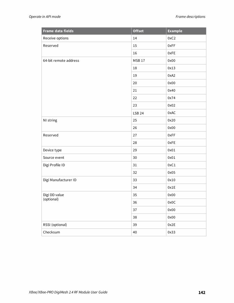
Operate in API mode Frame descriptions
XBee/XBee-PRO DigiMesh 2.4 RF Module User Guide 142
Frame data fields Offset Example
Receive options 14 0xC2
Reserved 15 0xFF
16 0xFE
64-bit remote address MSB 17 0x00
18 0x13
19 0xA2
20 0x00
21 0x40
22 0x74
23 0x02
LSB 24 0xAC
NI string 25 0x20
26 0x00
Reserved 27 0xFF
28 0xFE
Device type 29 0x01
Source event 30 0x01
Digi Profile ID 31 0xC1
32 0x05
Digi Manufacturer ID 33 0x10
34 0x1E
Digi DD value(optional)
35 0x00
36 0x0C
37 0x00
38 0x00
RSSI (optional) 39 0x2E
Checksum 40 0x33
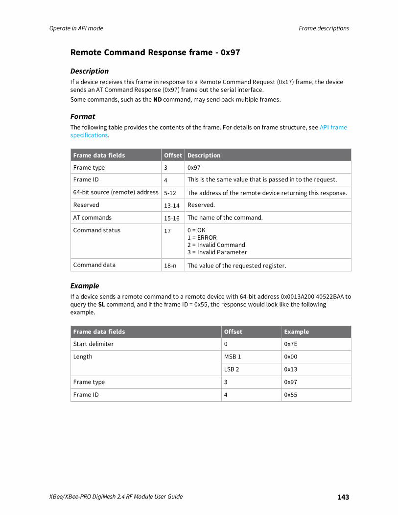
Operate in API mode Frame descriptions
XBee/XBee-PRO DigiMesh 2.4 RF Module User Guide 143
Remote Command Response frame - 0x97
DescriptionIf a device receives this frame in response to a Remote Command Request (0x17) frame, the devicesends an AT Command Response (0x97) frame out the serial interface.Some commands, such as the ND command, may send back multiple frames.
FormatThe following table provides the contents of the frame. For details on frame structure, see API framespecifications.
Frame data fields Offset Description
Frame type 3 0x97
Frame ID 4 This is the same value that is passed in to the request.
64-bit source (remote) address 5-12 The address of the remote device returning this response.
Reserved 13-14 Reserved.
AT commands 15-16 The name of the command.
Command status 17 0 = OK1 = ERROR2 = Invalid Command3 = Invalid Parameter
Command data 18-n The value of the requested register.
ExampleIf a device sends a remote command to a remote device with 64-bit address 0x0013A200 40522BAA toquery the SL command, and if the frame ID = 0x55, the response would look like the followingexample.
Frame data fields Offset Example
Start delimiter 0 0x7E
Length MSB 1 0x00
LSB 2 0x13
Frame type 3 0x97
Frame ID 4 0x55
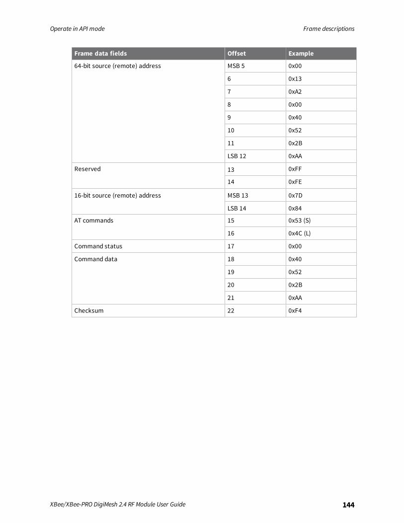
Operate in API mode Frame descriptions
XBee/XBee-PRO DigiMesh 2.4 RF Module User Guide 144
Frame data fields Offset Example
64-bit source (remote) address MSB 5 0x00
6 0x13
7 0xA2
8 0x00
9 0x40
10 0x52
11 0x2B
LSB 12 0xAA
Reserved 13 0xFF
14 0xFE
16-bit source (remote) address MSB 13 0x7D
LSB 14 0x84
AT commands 15 0x53 (S)
16 0x4C (L)
Command status 17 0x00
Command data 18 0x40
19 0x52
20 0x2B
21 0xAA
Checksum 22 0xF4
Regulatory information
United States (FCC) 146Australia (C-Tick) 153Brazil ANATEL 153ISED (Innovation, Science and Economic Development Canada) 154Europe 154Japan 156
XBee/XBee-PRO DigiMesh 2.4 RF Module User Guide 145

Regulatory information United States (FCC)
XBee/XBee-PRO DigiMesh 2.4 RF Module User Guide 146
United States (FCC)XBee/XBee-PRO RF Modules comply with Part 15 of the FCC rules and regulations. Compliance withthe labeling requirements, FCC notices and antenna usage guidelines is required.To fulfill FCC certification requirements, the OEM must comply with the following regulations:
n The system integrator must ensure that the text on the external label provided with thisdevice is placed on the outside of the final product.
n XBee/XBee-PRO RF modules may only be used with antennas that have been tested andapproved for use with this module; refer to FCC-approved antennas (2.4 GHz).
OEM labeling requirements
WARNING! As an Original Equipment Manufacturer (OEM) you must ensure that FCClabeling requirements are met. You must include a clearly visible label on the outside ofthe final product enclosure that displays the following content:
Contains FCC ID: OUR-XBEE/OUR-XBEEPRO1
The enclosed device complies with Part 15 of the FCC Rules. Operation is subject to thefollowing two conditions: (i. ) this device may not cause harmful interference and (ii. ) thisdevice must accept any interference received, including interference that may cause undesiredoperation.
FCC noticesIMPORTANT: The XBee / XBee-PRO RF Module has been certified by the FCC for use with otherproducts without any further certification (as per FCC section 2.1091). Modifications not expresslyapproved by Digi could void the user's authority to operate the equipment.IMPORTANT: OEMs must test final product to comply with unintentional radiators (FCC section 15.107and 15.109) before declaring compliance of their final product to Part 15 of the FCC rules.IMPORTANT: The RF module has been certified for remote and base radio applications. If the modulewill be used for portable applications, please take note of the following instructions:
n For XBee modules where the antenna gain is less than 13.8 dBi, no additional SAR testing isrequired. The 20 cm separation distance is not required for antenna gain less than 13.8 dBi.
n For XBee modules where the antenna gain is greater than 13.8 dBi and for all XBee-PROmodules, the device must undergo SAR testing.
This equipment has been tested and found to comply with the limits for a Class B digital device,pursuant to Part 15 of the FCC Rules. These limits are designed to provide reasonable protectionagainst harmful interference in a residential installation. This equipment generates, uses and canradiate radio frequency energy and, if not installed and used in accordance with the instructions, maycause harmful interference to radio communications. However, there is no guarantee thatinterference will not occur in a particular installation.If this equipment does cause harmful interference to radio or television reception, which can bedetermined by turning the equipment off and on, the user is encouraged to try to correct theinterference by one or more of the following measures:
1The FCC ID for the XBee is “OUR-XBEE.” The FCC ID for the XBee-PRO is “OUR-XBEEPRO.”
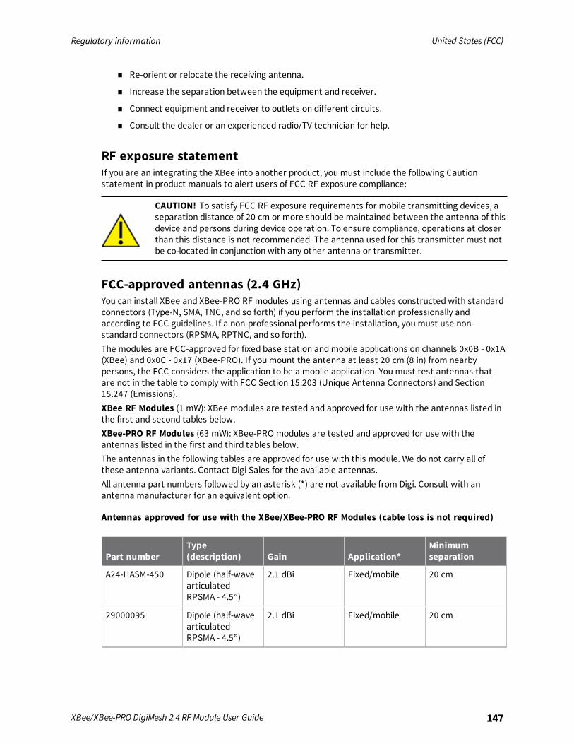
Regulatory information United States (FCC)
XBee/XBee-PRO DigiMesh 2.4 RF Module User Guide 147
n Re-orient or relocate the receiving antenna.
n Increase the separation between the equipment and receiver.
n Connect equipment and receiver to outlets on different circuits.
n Consult the dealer or an experienced radio/TV technician for help.
RF exposure statementIf you are an integrating the XBee into another product, you must include the following Cautionstatement in product manuals to alert users of FCC RF exposure compliance:
CAUTION! To satisfy FCC RF exposure requirements for mobile transmitting devices, aseparation distance of 20 cm or more should be maintained between the antenna of thisdevice and persons during device operation. To ensure compliance, operations at closerthan this distance is not recommended. The antenna used for this transmitter must notbe co-located in conjunction with any other antenna or transmitter.
FCC-approved antennas (2.4 GHz)You can install XBee and XBee-PRO RF modules using antennas and cables constructed with standardconnectors (Type-N, SMA, TNC, and so forth) if you perform the installation professionally andaccording to FCC guidelines. If a non-professional performs the installation, you must use non-standard connectors (RPSMA, RPTNC, and so forth).The modules are FCC-approved for fixed base station andmobile applications on channels 0x0B - 0x1A(XBee) and 0x0C - 0x17 (XBee-PRO). If you mount the antenna at least 20 cm (8 in) from nearbypersons, the FCC considers the application to be a mobile application. You must test antennas thatare not in the table to comply with FCC Section 15.203 (Unique Antenna Connectors) and Section15.247 (Emissions).XBee RF Modules (1 mW): XBee modules are tested and approved for use with the antennas listed inthe first and second tables below.XBee-PRO RF Modules (63 mW): XBee-PRO modules are tested and approved for use with theantennas listed in the first and third tables below.The antennas in the following tables are approved for use with this module. We do not carry all ofthese antenna variants. Contact Digi Sales for the available antennas.All antenna part numbers followed by an asterisk (*) are not available from Digi. Consult with anantenna manufacturer for an equivalent option.
Antennas approved for use with the XBee/XBee-PRO RF Modules (cable loss is not required)
Part numberType(description) Gain Application*
Minimumseparation
A24-HASM-450 Dipole (half-wavearticulatedRPSMA - 4.5”)
2.1 dBi Fixed/mobile 20 cm
29000095 Dipole (half-wavearticulatedRPSMA - 4.5”)
2.1 dBi Fixed/mobile 20 cm
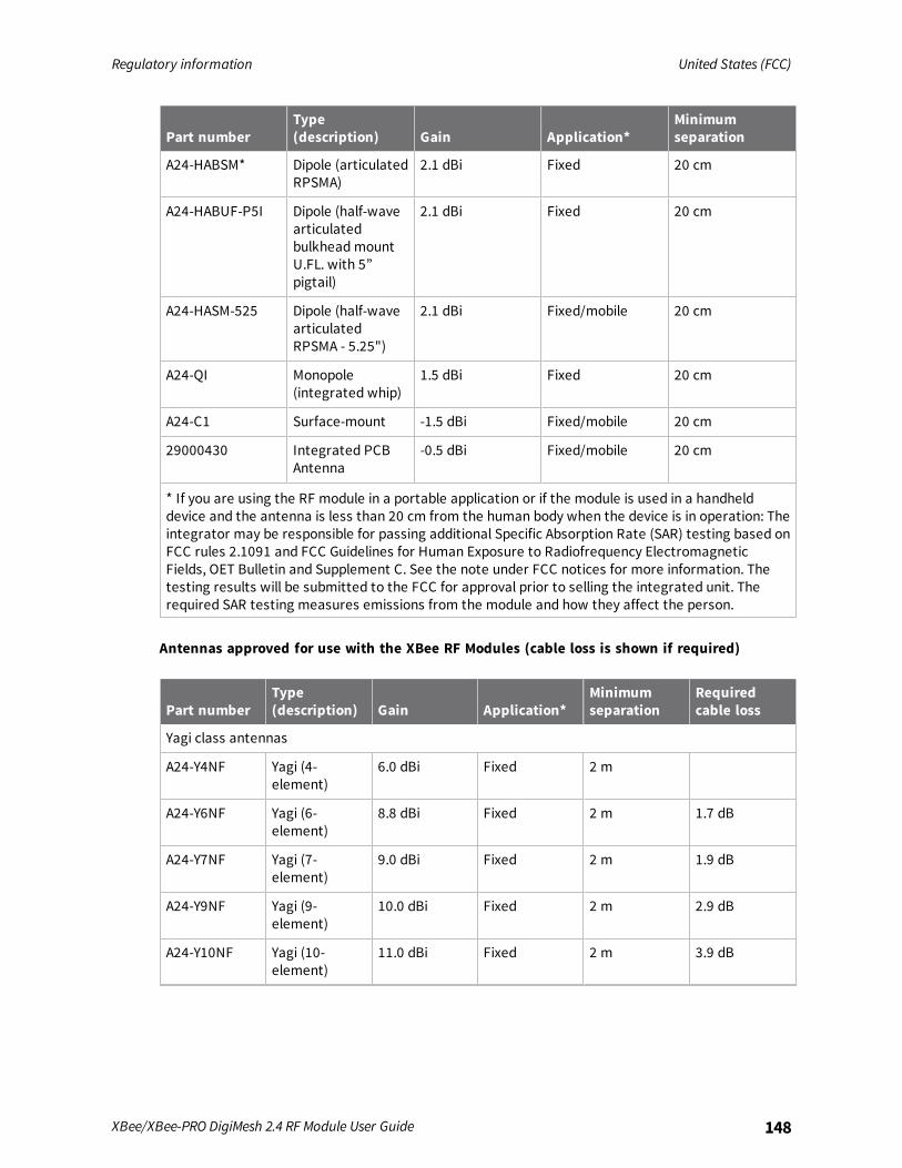
Regulatory information United States (FCC)
XBee/XBee-PRO DigiMesh 2.4 RF Module User Guide 148
Part numberType(description) Gain Application*
Minimumseparation
A24-HABSM* Dipole (articulatedRPSMA)
2.1 dBi Fixed 20 cm
A24-HABUF-P5I Dipole (half-wavearticulatedbulkheadmountU.FL. with 5”pigtail)
2.1 dBi Fixed 20 cm
A24-HASM-525 Dipole (half-wavearticulatedRPSMA - 5.25")
2.1 dBi Fixed/mobile 20 cm
A24-QI Monopole(integrated whip)
1.5 dBi Fixed 20 cm
A24-C1 Surface-mount -1.5 dBi Fixed/mobile 20 cm
29000430 Integrated PCBAntenna
-0.5 dBi Fixed/mobile 20 cm
* If you are using the RF module in a portable application or if the module is used in a handhelddevice and the antenna is less than 20 cm from the human body when the device is in operation: Theintegrator may be responsible for passing additional Specific Absorption Rate (SAR) testing based onFCC rules 2.1091 and FCC Guidelines for Human Exposure to Radiofrequency ElectromagneticFields, OET Bulletin and Supplement C. See the note under FCC notices for more information. Thetesting results will be submitted to the FCC for approval prior to selling the integrated unit. Therequired SAR testing measures emissions from the module and how they affect the person.
Antennas approved for use with the XBee RF Modules (cable loss is shown if required)
Part numberType(description) Gain Application*
Minimumseparation
Requiredcable loss
Yagi class antennas
A24-Y4NF Yagi (4-element)
6.0 dBi Fixed 2 m
A24-Y6NF Yagi (6-element)
8.8 dBi Fixed 2 m 1.7 dB
A24-Y7NF Yagi (7-element)
9.0 dBi Fixed 2 m 1.9 dB
A24-Y9NF Yagi (9-element)
10.0 dBi Fixed 2 m 2.9 dB
A24-Y10NF Yagi (10-element)
11.0 dBi Fixed 2 m 3.9 dB
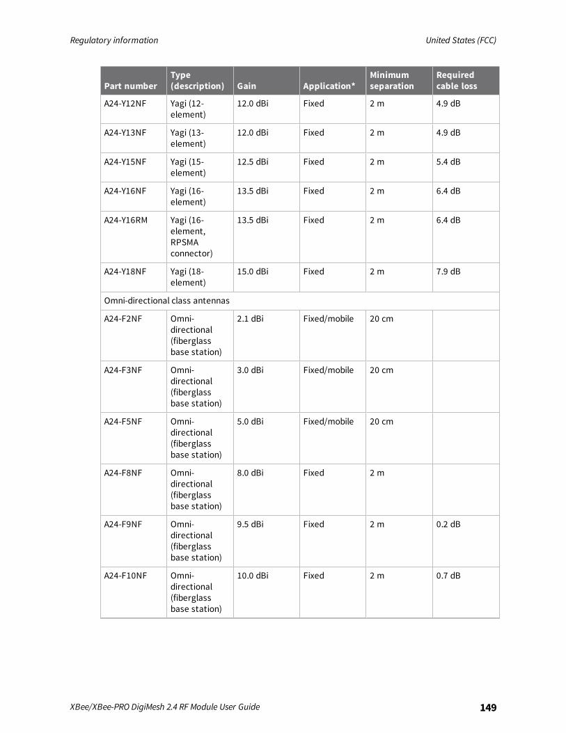
Regulatory information United States (FCC)
XBee/XBee-PRO DigiMesh 2.4 RF Module User Guide 149
Part numberType(description) Gain Application*
Minimumseparation
Requiredcable loss
A24-Y12NF Yagi (12-element)
12.0 dBi Fixed 2 m 4.9 dB
A24-Y13NF Yagi (13-element)
12.0 dBi Fixed 2 m 4.9 dB
A24-Y15NF Yagi (15-element)
12.5 dBi Fixed 2 m 5.4 dB
A24-Y16NF Yagi (16-element)
13.5 dBi Fixed 2 m 6.4 dB
A24-Y16RM Yagi (16-element,RPSMAconnector)
13.5 dBi Fixed 2 m 6.4 dB
A24-Y18NF Yagi (18-element)
15.0 dBi Fixed 2 m 7.9 dB
Omni-directional class antennas
A24-F2NF Omni-directional(fiberglassbase station)
2.1 dBi Fixed/mobile 20 cm
A24-F3NF Omni-directional(fiberglassbase station)
3.0 dBi Fixed/mobile 20 cm
A24-F5NF Omni-directional(fiberglassbase station)
5.0 dBi Fixed/mobile 20 cm
A24-F8NF Omni-directional(fiberglassbase station)
8.0 dBi Fixed 2 m
A24-F9NF Omni-directional(fiberglassbase station)
9.5 dBi Fixed 2 m 0.2 dB
A24-F10NF Omni-directional(fiberglassbase station)
10.0 dBi Fixed 2 m 0.7 dB
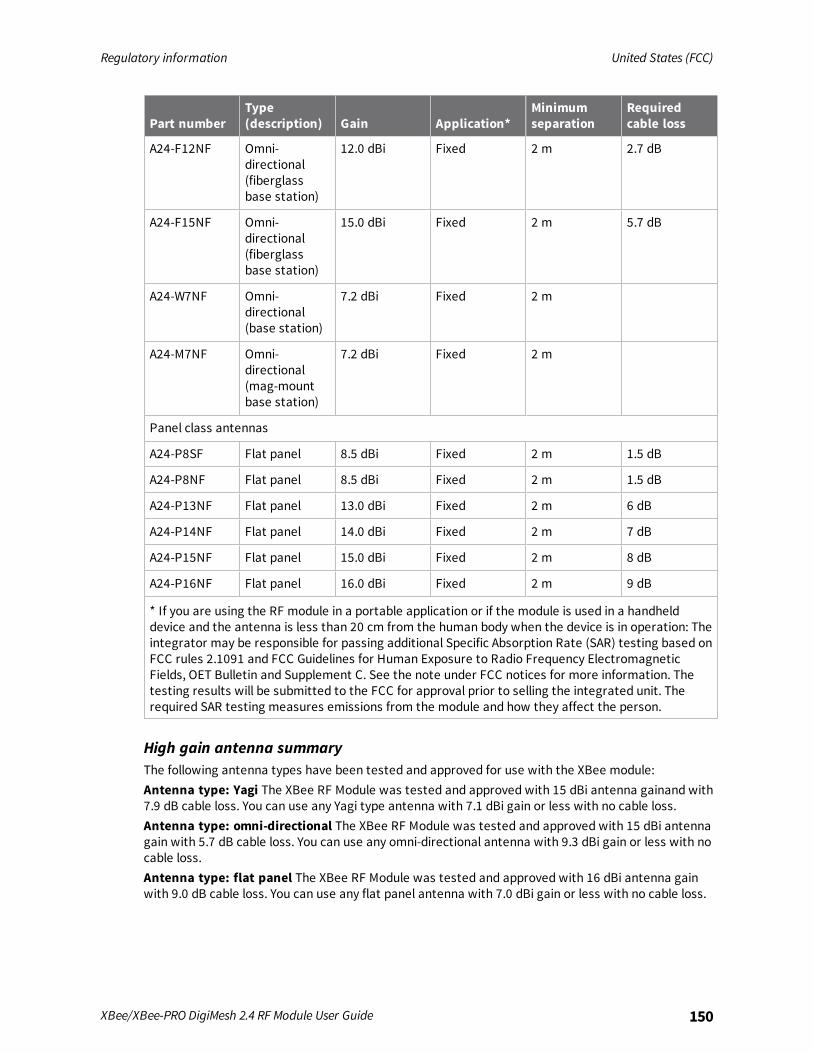
Regulatory information United States (FCC)
XBee/XBee-PRO DigiMesh 2.4 RF Module User Guide 150
Part numberType(description) Gain Application*
Minimumseparation
Requiredcable loss
A24-F12NF Omni-directional(fiberglassbase station)
12.0 dBi Fixed 2 m 2.7 dB
A24-F15NF Omni-directional(fiberglassbase station)
15.0 dBi Fixed 2 m 5.7 dB
A24-W7NF Omni-directional(base station)
7.2 dBi Fixed 2 m
A24-M7NF Omni-directional(mag-mountbase station)
7.2 dBi Fixed 2 m
Panel class antennas
A24-P8SF Flat panel 8.5 dBi Fixed 2 m 1.5 dB
A24-P8NF Flat panel 8.5 dBi Fixed 2 m 1.5 dB
A24-P13NF Flat panel 13.0 dBi Fixed 2 m 6 dB
A24-P14NF Flat panel 14.0 dBi Fixed 2 m 7 dB
A24-P15NF Flat panel 15.0 dBi Fixed 2 m 8 dB
A24-P16NF Flat panel 16.0 dBi Fixed 2 m 9 dB
* If you are using the RF module in a portable application or if the module is used in a handhelddevice and the antenna is less than 20 cm from the human body when the device is in operation: Theintegrator may be responsible for passing additional Specific Absorption Rate (SAR) testing based onFCC rules 2.1091 and FCC Guidelines for Human Exposure to Radio Frequency ElectromagneticFields, OET Bulletin and Supplement C. See the note under FCC notices for more information. Thetesting results will be submitted to the FCC for approval prior to selling the integrated unit. Therequired SAR testing measures emissions from the module and how they affect the person.
High gain antenna summaryThe following antenna types have been tested and approved for use with the XBee module:Antenna type: Yagi The XBee RF Module was tested and approved with 15 dBi antenna gainand with7.9 dB cable loss. You can use any Yagi type antenna with 7.1 dBi gain or less with no cable loss.Antenna type: omni-directional The XBee RF Module was tested and approved with 15 dBi antennagain with 5.7 dB cable loss. You can use any omni-directional antenna with 9.3 dBi gain or less with nocable loss.Antenna type: flat panel The XBee RF Module was tested and approved with 16 dBi antenna gainwith 9.0 dB cable loss. You can use any flat panel antenna with 7.0 dBi gain or less with no cable loss.
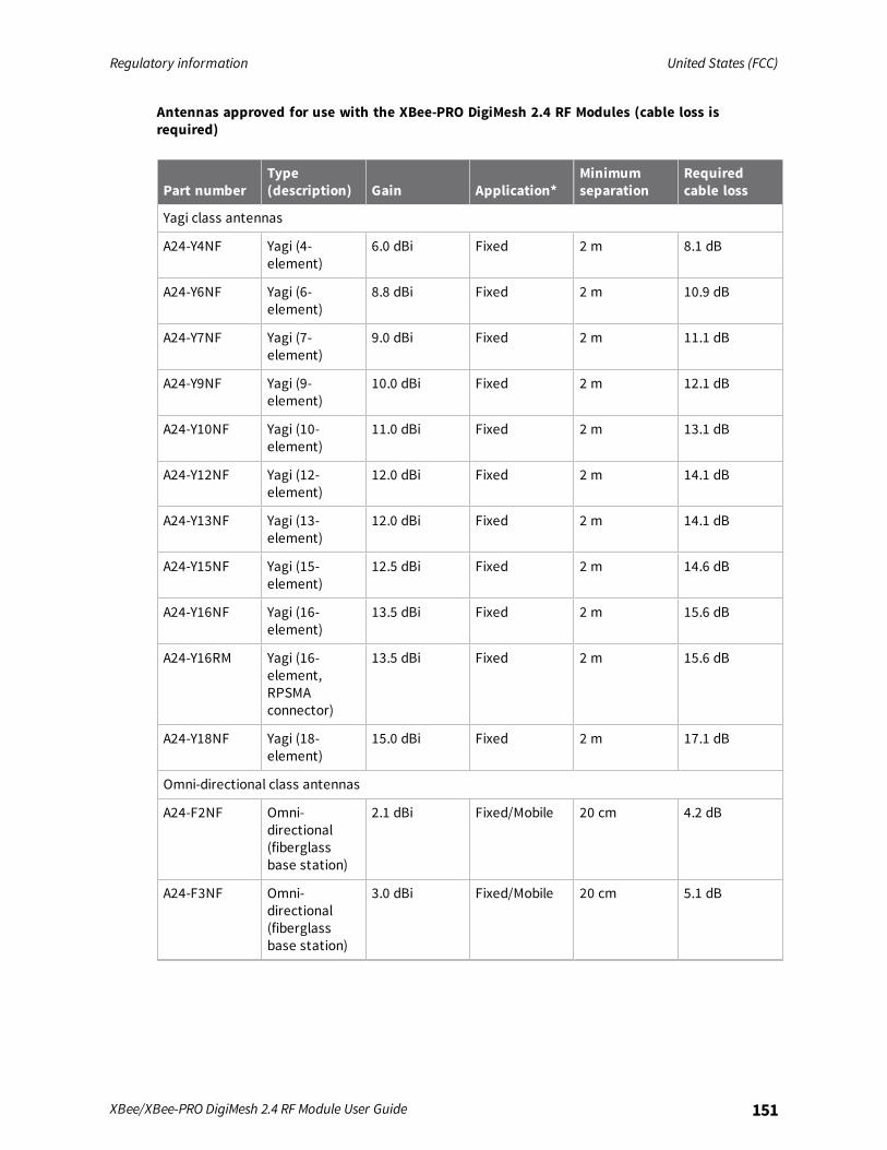
Regulatory information United States (FCC)
XBee/XBee-PRO DigiMesh 2.4 RF Module User Guide 151
Antennas approved for use with the XBee-PRO DigiMesh 2.4 RF Modules (cable loss isrequired)
Part numberType(description) Gain Application*
Minimumseparation
Requiredcable loss
Yagi class antennas
A24-Y4NF Yagi (4-element)
6.0 dBi Fixed 2 m 8.1 dB
A24-Y6NF Yagi (6-element)
8.8 dBi Fixed 2 m 10.9 dB
A24-Y7NF Yagi (7-element)
9.0 dBi Fixed 2 m 11.1 dB
A24-Y9NF Yagi (9-element)
10.0 dBi Fixed 2 m 12.1 dB
A24-Y10NF Yagi (10-element)
11.0 dBi Fixed 2 m 13.1 dB
A24-Y12NF Yagi (12-element)
12.0 dBi Fixed 2 m 14.1 dB
A24-Y13NF Yagi (13-element)
12.0 dBi Fixed 2 m 14.1 dB
A24-Y15NF Yagi (15-element)
12.5 dBi Fixed 2 m 14.6 dB
A24-Y16NF Yagi (16-element)
13.5 dBi Fixed 2 m 15.6 dB
A24-Y16RM Yagi (16-element,RPSMAconnector)
13.5 dBi Fixed 2 m 15.6 dB
A24-Y18NF Yagi (18-element)
15.0 dBi Fixed 2 m 17.1 dB
Omni-directional class antennas
A24-F2NF Omni-directional(fiberglassbase station)
2.1 dBi Fixed/Mobile 20 cm 4.2 dB
A24-F3NF Omni-directional(fiberglassbase station)
3.0 dBi Fixed/Mobile 20 cm 5.1 dB
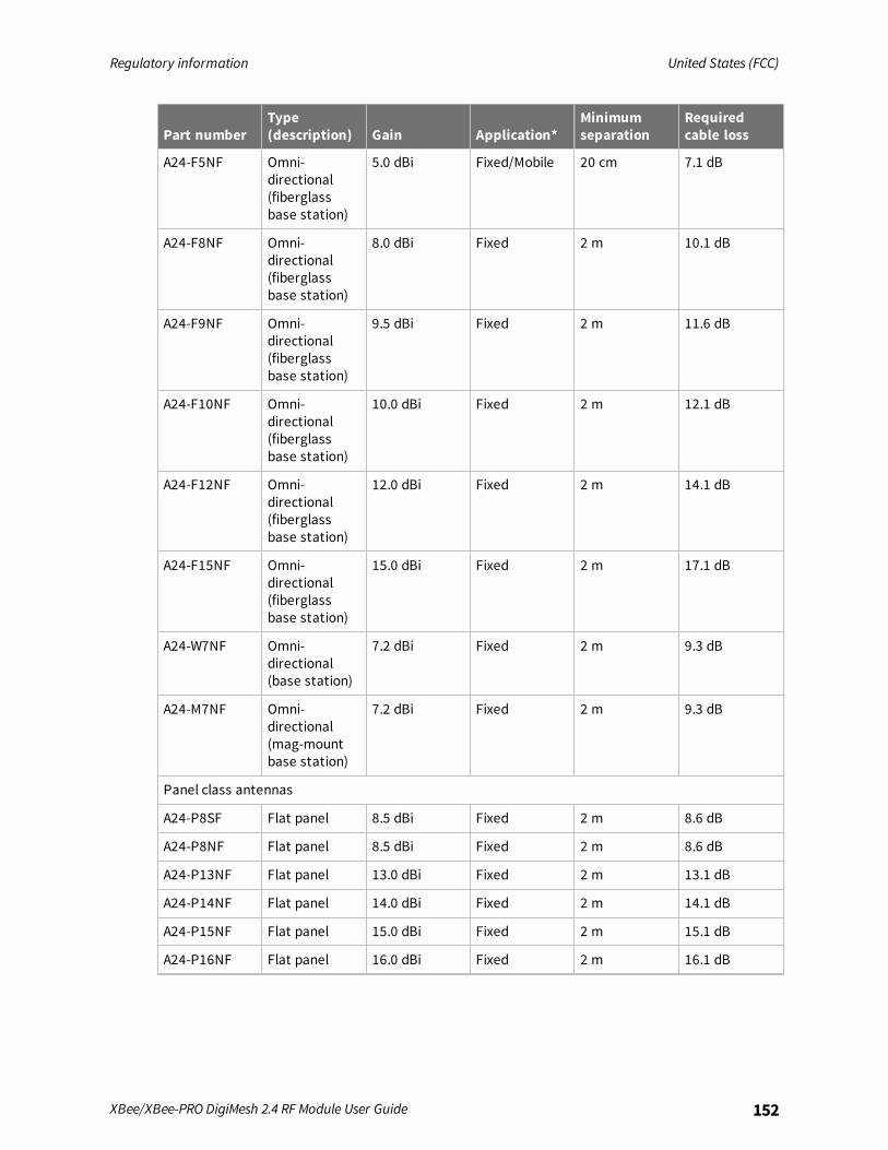
Regulatory information United States (FCC)
XBee/XBee-PRO DigiMesh 2.4 RF Module User Guide 152
Part numberType(description) Gain Application*
Minimumseparation
Requiredcable loss
A24-F5NF Omni-directional(fiberglassbase station)
5.0 dBi Fixed/Mobile 20 cm 7.1 dB
A24-F8NF Omni-directional(fiberglassbase station)
8.0 dBi Fixed 2 m 10.1 dB
A24-F9NF Omni-directional(fiberglassbase station)
9.5 dBi Fixed 2 m 11.6 dB
A24-F10NF Omni-directional(fiberglassbase station)
10.0 dBi Fixed 2 m 12.1 dB
A24-F12NF Omni-directional(fiberglassbase station)
12.0 dBi Fixed 2 m 14.1 dB
A24-F15NF Omni-directional(fiberglassbase station)
15.0 dBi Fixed 2 m 17.1 dB
A24-W7NF Omni-directional(base station)
7.2 dBi Fixed 2 m 9.3 dB
A24-M7NF Omni-directional(mag-mountbase station)
7.2 dBi Fixed 2 m 9.3 dB
Panel class antennas
A24-P8SF Flat panel 8.5 dBi Fixed 2 m 8.6 dB
A24-P8NF Flat panel 8.5 dBi Fixed 2 m 8.6 dB
A24-P13NF Flat panel 13.0 dBi Fixed 2 m 13.1 dB
A24-P14NF Flat panel 14.0 dBi Fixed 2 m 14.1 dB
A24-P15NF Flat panel 15.0 dBi Fixed 2 m 15.1 dB
A24-P16NF Flat panel 16.0 dBi Fixed 2 m 16.1 dB
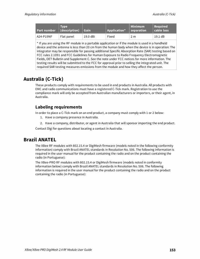
Regulatory information Australia (C-Tick)
XBee/XBee-PRO DigiMesh 2.4 RF Module User Guide 153
Part numberType(description) Gain Application*
Minimumseparation
Requiredcable loss
A24-P19NF Flat panel 19.0 dBi Fixed 2 m 19.1 dB
* If you are using the RF module in a portable application or if the module is used in a handhelddevice and the antenna is less than 20 cm from the human body when the device is in operation: Theintegrator may be responsible for passing additional Specific Absorption Rate (SAR) testing based onFCC rules 2.1091 and FCC Guidelines for Human Exposure to Radio Frequency ElectromagneticFields, OET Bulletin and Supplement C. See the note under FCC notices for more information. Thetesting results will be submitted to the FCC for approval prior to selling the integrated unit. Therequired SAR testing measures emissions from the module and how they affect the person.
Australia (C-Tick)These products comply with requirements to be used in end products in Australia. All products withEMC and radio communications must have a registered C-Tick mark. Registration to use thecompliance mark will only be accepted from Australian manufacturers or importers, or their agent, inAustralia.
Labeling requirementsIn order to place a C-Tick mark on an end product, a company must comply with 1 or 2 below:
1. Have a company presence in Australia.
2. Have a company, distributor, or agent in Australia that will sponsor importing the end product.
Contact Digi for questions about locating a contact in Australia.
Brazil ANATELThe XBee RF modules with 802.15.4 or DigiMesh firmware (models noted in the following conformityinformation) comply with Brazil ANATEL standards in Resolution No. 506. The following information isrequired in the user manual for the product containing the radio and on the product containing theradio (in Portuguese):The XBee-PRO RF modules with 802.15.4 or DigiMesh firmware (models noted in conformityinformation below) comply with Brazil ANATEL standards in Resolution No. 506. The followinginformation is required in the user manual for the product containing the radio and on the productcontaining the radio (in Portuguese):

Regulatory information ISED (Innovation, Science and Economic Development Canada)
XBee/XBee-PRO DigiMesh 2.4 RF Module User Guide 154
Modelo XBee-Pro S3B:
ISED (Innovation, Science and Economic Development Canada)
Labeling requirementsIC requires you to place a clearly visible label on the outside of the final product enclosure, displayingthe following text:
Contains Model XBee Radio, IC: 4214A-XBEEContains Model XBee-PRO Radio, IC: 4214A-XBEEPRO
The integrator is responsible for its product to comply with IC ICES-003 & FCC Part 15, Sub. B -Unintentional Radiators. ICES-003 is the same as FCC Part 15 Sub. B and Industry Canada acceptsFCC test report or CISPR 22 test report for compliance with ICES-003.
EuropeThe RF Module is certified for use in several European countries; for a complete list, go to digi.com.If the XBee/XBee-PRO DigiMesh 2.4 is incorporated into a product, the manufacturer must ensurecompliance of the final product with articles 3.1a and 3.1b of the RE Directive (Radio EquipmentDirective). A Declaration of Conformity must be issued for each of these standards and kept on file asdescribed in the RE Directive (Radio Equipment Directive).
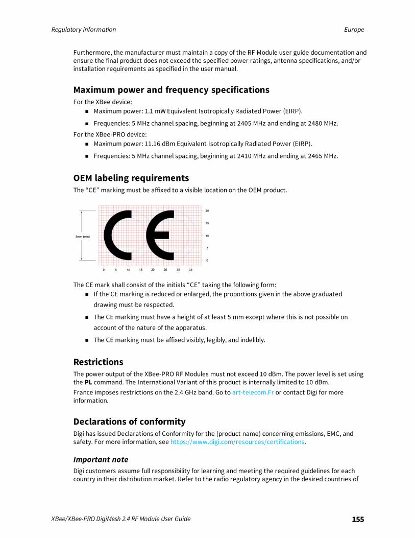
Regulatory information Europe
XBee/XBee-PRO DigiMesh 2.4 RF Module User Guide 155
Furthermore, the manufacturer must maintain a copy of the RF Module user guide documentation andensure the final product does not exceed the specified power ratings, antenna specifications, and/orinstallation requirements as specified in the user manual.
Maximum power and frequency specificationsFor the XBee device:
n Maximum power: 1.1 mW Equivalent Isotropically Radiated Power (EIRP).
n Frequencies: 5 MHz channel spacing, beginning at 2405 MHz and ending at 2480 MHz.
For the XBee-PRO device:n Maximum power: 11.16 dBm Equivalent Isotropically Radiated Power (EIRP).
n Frequencies: 5 MHz channel spacing, beginning at 2410 MHz and ending at 2465 MHz.
OEM labeling requirementsThe “CE” marking must be affixed to a visible location on the OEM product.
The CE mark shall consist of the initials “CE” taking the following form:n If the CE marking is reduced or enlarged, the proportions given in the above graduated
drawing must be respected.
n The CE marking must have a height of at least 5 mm except where this is not possible onaccount of the nature of the apparatus.
n The CE marking must be affixed visibly, legibly, and indelibly.
RestrictionsThe power output of the XBee-PRO RF Modules must not exceed 10 dBm. The power level is set usingthe PL command. The International Variant of this product is internally limited to 10 dBm.France imposes restrictions on the 2.4 GHz band. Go to art-telecom.Fr or contact Digi for moreinformation.
Declarations of conformityDigi has issued Declarations of Conformity for the (product name) concerning emissions, EMC, andsafety. For more information, see https://www.digi.com/resources/certifications.
Important noteDigi customers assume full responsibility for learning andmeeting the required guidelines for eachcountry in their distribution market. Refer to the radio regulatory agency in the desired countries of
Regulatory information Japan
XBee/XBee-PRO DigiMesh 2.4 RF Module User Guide 156
operation for more information.
Approved antennasWhen you integrate high-gain antennas, European regulations stipulate the EIRP power maximums.Use the following guidelines to determine which antennas to use when you design an application.All antenna part numbers followed by an asterisk (*) are not available from Digi. Consult with anantenna manufacturer for an equivalent option.The following antenna types are tested and approved for use with the XBee Module:
YagiRF module was tested and approved with 15 dBi antenna gain with 1 dB cable-loss (EIRP Maximum of14 dBm). Any Yagi type antenna with 14 dBi gain or less can be used with no cable-loss.
Omni-directionalRF module was tested and approved with 15 dBi antenna gain with 1 dB cable-loss (EIRP Maximum of14 dBm). Any Omni-directional type antenna with 14 dBi gain or less can be used with no cable-loss.
Flat panelRF module was tested and approved with 19 dBi antenna gain with 4.8 dB cable-loss (EIRP Maximumof 14.2 dBm). Any Flat Panel type antenna with 14.2 dBi gain or less can be used with no cable-loss.The embedded XBee-PRO was tested and approved for use with the following antennas:
Note At 10 dBm transmit power, the PL parameter value must equal 0, or you must use theinternational variant.
Dipole2.1 dBi, omni-directional, articulated RPSMA, Digi part number A24-HABSM*.
Chip antenna-1.5 dBi.
Attached monopole whip1.5 dBi.
Integrated PCB antenna-0.5 dBiThe RF modem encasement was designed to accommodate the RPSMA antenna option.
JapanIn order to use the XBee-PRO in Japan, you must order the International version. The InternationalXBee-PRO RF Modules are limited to a transmit power output of 10 dBm (10 mW).
Labeling requirementsA clearly visible label on the outside of the final product enclosure must display the following text:

Regulatory information Japan
XBee/XBee-PRO DigiMesh 2.4 RF Module User Guide 157
R201WW07215214 (XBee)R201WW08215111 (XBee-PRO)


