
X-treme & Standard Duty Auger Drives - cidattachments.com€¦ · Save this manual for future...
20
Save this manual for future reference! X-treme & Standard Duty Auger Drives Owner’s/Operator’s Manual Construction Implements Depot, Inc 1248 N. Main Street Denton, NC 27239 (336) 859-2002 For safe operation, read these rules and instructions carefully to avoid accidents that could result in Death or Serious Injury. TO THE OWNER/OPERATOR OF THIS IMPLEMENT Please read this manual “before” unpacking or using this implement for the first time. This manual provides you with the necessary instructions to safely install and use your purchase. Do not let other people use this attachment without first being instructed how to safely use it.
Transcript of X-treme & Standard Duty Auger Drives - cidattachments.com€¦ · Save this manual for future...

Save this manual for future reference!
X-treme & Standard Duty
Auger Drives
Owner’s/Operator’s Manual
Construction Implements Depot, Inc 1248 N. Main Street
Denton, NC 27239
(336) 859-2002
For safe operation, read these rules and instructions carefully to avoid accidents that could result in Death or Serious Injury.
TO THE OWNER/OPERATOR OF THIS IMPLEMENT Please read this manual “before” unpacking or using this implement for the first time. This manual provides you with the necessary instructions to safely install and use your purchase. Do not let other people use this attachment without first being instructed how to safely use it.

Construction Implements Depot PAGE 2 Auger Drives July 2014
Thank You Our sincere appreciation to you on the purchase of a quality Auger Drive designed and manufactured in the USA by Construction Implements Depot, Incorporated. Product experience of a combined 30 years is the cornerstone of our company, and our goal is to provide you with a heavy duty product that will give you years of satisfaction and operation. Our record of successful and satisfied customers is evidence of the concern for quality and designed strength that we place into each and every product we build. As this manual expresses the need for safe operation of your acquisition from Construction Implements Depot, Inc, it is important that you and all operators of this implement become familiar with the operation, maintenance and safety instructions found in this manual, as well as in the manual that accompanied the skid steer machine that will power this attachment. Add some common sense to the items mentioned in these manuals as the recipe for safe operation. We invite you to look at more innovative products on our web site: http://www.cidattachments.com or if in the area stop and visit our modern manufacturing facilities located in Denton, NC. Sincerely, Management & Employees Construction Implements Depot, Inc.
Information Record product information here for future reference. Model () X-treme Auger Drive:
Hex Drive _____ Round Drive _____
Standard Duty Auger Drive: _____
S/N or MFG. Date ______________
Dealer Name _________________
Dealer Phone ____-_____-_______
Date of Purchase ___/____/______
Construction Implements Depot PAGE 3 Auger Drives July 2014
Table of Contents Thank You ........................................... 2
Information ......................................... 2
Orientation ......................................... 3
Importance of Safety .......................... 3
Operator Safety Training Tips ............. 4
Skid Steer Requirements .................... 5
Unpacking Your Shipment .................. 5
Using Your Implement ........................ 5
Connecting Auger Drive to Skid Steer ............................................... 5
Pre-Operation Walk-around Inspection ....................................... 6
Auger Drive Controls ...................... 6
Before the First Hole ...................... 6
Stopping the Auger ........................ 7
Getting Familiar with the Attachment .................................... 7
Adjusting Auger Height .................. 8
Installing the Auger Bit ................... 8
Starting the Job .............................. 8
Adding an Extension ....................... 9
Drilling Tips ..................................... 9
Maintaining your Attachment .......... 10
Modifications ............................... 10
Before Every Use .......................... 10
After Every Use ............................. 11
After Every Season ....................... 11
Hydraulic System .......................... 11
Hardware Torque ......................... 11
Parts .................................................. 12
Standard Duty Auger Drive........... 13
X-treme Auger Drive..................... 14
Decals ........................................... 15
Troubleshooting ............................... 16
Specifications .................................... 17
Limited Warranty .............................. 20
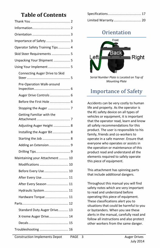
Orientation
Serial Number Plate is Located on Top of
Mounting Plate
Importance of Safety Accidents can be very costly to human life and property. As the operator is the #1 safety device on all types of vehicles or equipment, it is important that the operator read, learn and know all safety recommendations for this product. The user is responsible to his family, friends and co-workers to operate in a safe manner. Ensure that everyone who operates or assists in the operation or maintenance of this product read and understand all the elements required to safely operate this piece of equipment. This attachment has spinning parts that include additional dangers. Throughout this manual you will find safety notes which are very important to read and understand before operating this piece of equipment. These classifications alert you to situations that could be harmful to you or bystanders. When you see these alerts in the manual, carefully read and follow all instructions and also protect other workers from the same danger.
Construction Implements Depot PAGE 4 Auger Drives July 2014
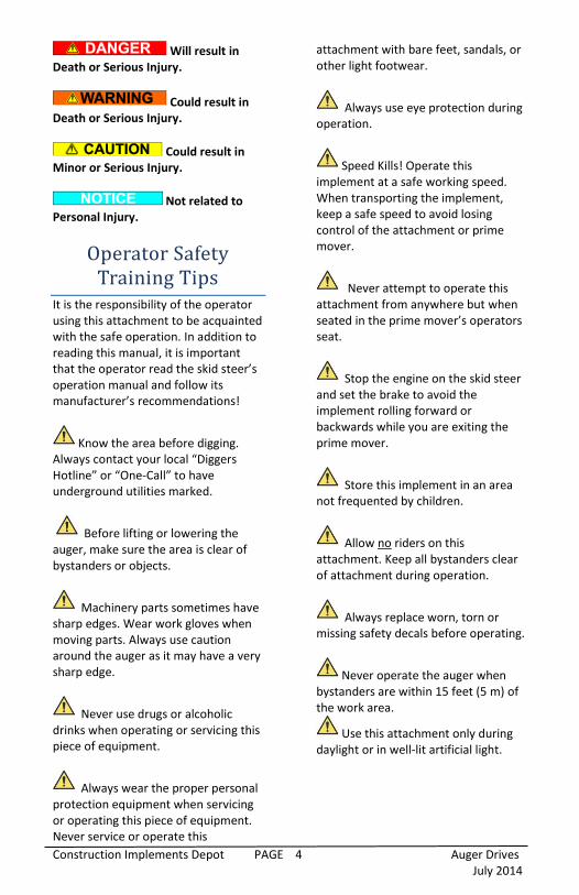
Will result in Death or Serious Injury.
Could result in Death or Serious Injury.
Could result in Minor or Serious Injury.
Not related to Personal Injury.
Operator Safety Training Tips
It is the responsibility of the operator using this attachment to be acquainted with the safe operation. In addition to reading this manual, it is important that the operator read the skid steer’s operation manual and follow its manufacturer’s recommendations!
Know the area before digging. Always contact your local “Diggers Hotline” or “One-Call” to have underground utilities marked.
Before lifting or lowering the auger, make sure the area is clear of bystanders or objects.
Machinery parts sometimes have sharp edges. Wear work gloves when moving parts. Always use caution around the auger as it may have a very sharp edge.
Never use drugs or alcoholic drinks when operating or servicing this piece of equipment.
Always wear the proper personal protection equipment when servicing or operating this piece of equipment. Never service or operate this
attachment with bare feet, sandals, or other light footwear.
Always use eye protection during operation.
Speed Kills! Operate this implement at a safe working speed. When transporting the implement, keep a safe speed to avoid losing control of the attachment or prime mover.
Never attempt to operate this attachment from anywhere but when seated in the prime mover’s operators seat.
Stop the engine on the skid steer and set the brake to avoid the implement rolling forward or backwards while you are exiting the prime mover.
Store this implement in an area not frequented by children.
Allow no riders on this attachment. Keep all bystanders clear of attachment during operation.
Always replace worn, torn or missing safety decals before operating.
Never operate the auger when bystanders are within 15 feet (5 m) of the work area.
Use this attachment only during daylight or in well-lit artificial light.

Construction Implements Depot PAGE 5 Auger Drives July 2014
Skid Steer Requirements
Your auger attachment is compatible with attachment couplers on all major manufacturers’ skid steer machines. This auger should only be used on skid steers with a compatible attachment coupler. This attachment will satisfactorily work on skid steers with either a radial or vertical type of lift arm system. Although the operating steps might vary a little from a radial lift to a vertical lift, the basic function of the auger drive is the same.
Make sure your skid steer is in good working condition. Follow the operating instructions found in the manual that accompanied your skid steer. Failure to do so could result in Minor or Serious Injury.
Unpacking Your
Shipment Your auger drive attachment arrives from the factory banded to a wooden pallet, and requires no final assembly before use, except for installation of the auger tool.
Careless removal of the shipping bands that secure the implement to the pallet could result in Minor or Serious Injury. Clear the area of all bystanders and stand to the side when cutting the bands with a pair of sheet metal shears.
Using Your Implement
Connecting Auger Drive to Skid Steer
Never enter the area underneath the coupler or any part of the attachment when it is in the raised position to avoid an accident that will result in Death or Serious Injury. Verify that the hydraulic hoses are clear from the front of the attaching plate on the attachment and that the mounting plate is free from dirt and debris. When clear, move the skid steer to proximity of attachment plate. Tilt the skid steer coupler forward to align coupling point with the upper part on the back of the attachment plate and raise the coupler slightly.
Connecting Coupler to Attachment
When the top edge of the coupler is seated in the top part of the coupler plate, roll the skid steer tilt function back until the attaching plate is flat against the skid steer coupler. Lock down the coupler levers. Note: If your skid steer is equipped with a hydraulically operated coupler, activate the coupler lock at this time.

Construction Implements Depot PAGE 6 Auger Drives July 2014
Shut the Skid steer’s engine off and release the pressure in the auxiliary circuit.
Wipe off any dirt or dust from the male or female hydraulic flat-face couplers with a clean rag before attaching hoses to keep contaminants from entering the hydraulic system. Connect the attachment hydraulic hoses to the auxiliary supply couplers located on your skid steer loader lift arm. Check the surrounding area for bystanders and clear them before starting the skid steer or attachment. Before operating the attachment, always visually inspect and verify that the coupler lock pins are fully engaged through the latch slots on the attachment plate.
Check Coupler Lock Engagement
Pre-Operation Walk-around Inspection
Before every use, it is important to perform a short inspection and certain maintenance on your auger drive.
Item Check that all shields and
guards are in place. Look for loose bolts and
tighten them if necessary. Check that all safety decals
are in place and can be read. Replace them if necessary.
Check that the auger lock bolt has been installed and is secure. Check condition of auger bit and teeth.
Take care of our environment. Repair any hydraulic leaks.
Auger Drive Controls
Your Auger Drive is designed to operate from the skid steer’s auxiliary hydraulic system, and is operated by a control in the operator’s cab. Consult your skid steer operator’s manual for precise instructions on how to activate and deactivate the auxiliary circuit. Height and tilt functions of the auger drive are operated with the control handles or pedals in the cab. Consult your skid steers operator’s manual for precise instructions regarding these functions.
Before the First Hole
If this is your initial startup with this attachment on this machine, check the skid steer’s hydraulic oil level and add oil, if necessary, before and after doing steps 1, 2 & 3 below. After starting the skid steer, lift the attachment 6” (152mm) off the ground surface: 1. With the skid steer engine RPMs
just above idle, slowly engage the auxiliary hydraulic to rotate the auger bit and let it rotate for twenty seconds. Move the auxiliary control pedal, lever or

Construction Implements Depot PAGE 7 Auger Drives July 2014
switch in the opposite direction reversing the auger bit, letting it run for another twenty seconds. Repeat this twice.
2. Stop the auger rotation and tilt the attachment coupler back until the auger drive is in the transport position.
Auger drive in transport position
3. Lower the attachment to the
ground as you are reversing a few feet. When the auger is lying on the ground and the attachment coupler has been fully lowered, shut off the skid steer’s engine and exit the operator’s compartment.
4. Check the skid steers hydraulic oil level, and add oil if necessary.
5. Inspect the auger drive’s hydraulic plumbing for any noticeable leaks. Correct these leaks before continuing.
Stopping the Auger
The auger bit rotation quits moving when the auxiliary control is neutralized. When you are done drilling, place the auger bit on the ground and lower the attachment coupler to the ground before exiting the cab.
Getting Familiar with the Attachment
Never operate the auger when bystanders are within 15’ (5 m) of your work area. Flying debris or a swinging auger bit could result in Death or Serious Injury.
Be cautious when operating on un-level ground surfaces. A machine roll over could result in Minor or Serious Injury. Always wear your seat belt when operating this type of machinery. Before starting the skid steer engine with this auger attached, make sure you are knowledgeable and comfortable with the operation of the auxiliary controls as outlined in the skid steer owner’s manual. To begin with, when getting ready to drill a hole, tilt the attachment plate forward to allow the auger drive and bit to hang unsupported from the travel bunk on the attachment mount. Learn what the auger drive and auger bit look like in a plumb position when you are seated in the skid steer.
When the auger drive is not resting on the transport plate, move the skid steer very slowly to avoid unnecessary swinging of the auger drive and auger bit. When transporting this attachment, always be aware of your surroundings. While watching the auger, also pay attention to what obstacles or terrain are in front of the auger and also the prime mover’s wheels. Auger Speed – In soft, sandy soils, a faster auger rotation speed is usually desired, whereas in hard, frozen or

Construction Implements Depot PAGE 8 Auger Drives July 2014
rocky types of soil, a slower speed should be used. Recognize which direction will be used for rotating the auger bit into the ground. If the wrong direction is used, the auger bit will not penetrate the soil.
Adjusting Auger Height Use the skid steer loader lift to adjust the elevation of the auger (up & down).
Installing the Auger Bit Make sure the coupling end of the auger bit matches the size and shape of the output shaft on the auger drive unit.
X-treme Drive w/ 2 ” hex or
X-treme Drive w/ 2 9/16” round or
Standard Duty Drive w/ 2” round
Insert the auger bit on the auger drive output shaft, lining up the lock bolt hole. Insert the lock bolt and secure the hardware.
Align lock bolt hole on output shaft
Starting the Job
Know the area before digging. Always contact your local “Diggers Hotline” or “One-Call” to have underground utilities marked to avoid an accident that could result in Death or Serious Injury.
Moving or engaging the auger with bystanders in the area could result in Death or Serious Injury. Before engaging the auger hydraulics, always make sure the area is clear of bystanders.
Exposure to crystalline silica dust along with other hazardous dusts may cause serious or fatal respiratory disease. It is recommended to use dust suppression, dust collection and if necessary personal protective equipment during the operation of any attachment that may cause a high level of dust. 1. Identify and mark the spot for
your hole. Make sure you have verified that there are not any buried utilities in the area you plan on digging in.
2. Raise the skid steer’s lift arms and tilt the coupler forward to allow the auger drive to swing freely from the transport rest and center the auger about 1” (25 mm) above the intended hole spot. Allow the auger bit to self-center itself.
3. Raise the skid steer engine’s speed to about one-half throttle.
4. Start the auger drive before you lower the lift arm to enter the bit into the ground.
5. Apply slight down pressure on the auger with the lift arm circuit on the skid steer. If the engine RPM slows too much, decrease the

Construction Implements Depot PAGE 9 Auger Drives July 2014
amount of down pressure being applied to the auger bit.
6. When you have penetrated the soil to the point you want to clear the auger bit flights of soil, stop the rotation and slowly raise the auger bit from the hole as you slow the rotation. You can rid the soil from the bit two ways:
a. Counter rotate the skid steer and rotate the auger bit to shake off the dirt, or
b. Rotate the auger bit quickly in reverse to shed spoil from bit, depositing the dirt around the outside of the hole.
7. When returning to the hole, center the auger bit over the hole and lower the bit into the hole before beginning to spin the auger.
Adding an Extension
When it is necessary to make a hole with a depth deeper than the length of the auger bit allows, you can add an extension between the auger bit and auger drive. If the lift height of your skid steer allows it, connect the extension to the auger drive output shaft first, and then connect it to the auger bit. If the lift height on your skid steer is not high enough to connect the extension before the initial drilling, drill your hole down to the level near the ground surface. Disconnect the securing hardware from the auger and lift the drive out of the auger bit. Install the auger extension shaft on the auger drive and using the skid steer lift, lower it and insert it into the auger bit standing upright in the hole. Secure the extension to the auger bit with the correct hardware.
Once the hole has been drilled to the desired depth, use caution to avoid dropping the auger bit into the hole. Lift the auger to a height where the extension has been raised above ground level and the first few auger flights are visible. Shut the skid steer off. Have a fellow worker carefully clear some dirt (with a shovel from a safe distance) off the auger bit flighting in order to secure a notched hardwood board to keep the auger from falling back into the hole.
Notched board to hold bit
After the board has been put in place, start the skid steer and lower the auger drive so the auger bit weight is resting on the board. Remove the hardware securing the extension to the auger bit. Lift the extension out of the auger bit and then remove the extension from the auger drive. After the extension has been removed, reconnect the auger drive to the auger but and lift the auger bit out of the ground.
Drilling Tips
Never operate this attachment when bystanders are in proximity of the work area that could result in Minor or Serious Injury from flying debris or a swinging auger bit.

Construction Implements Depot PAGE 10 Auger Drives July 2014
Use care when operating on uneven terrain or any type of sloped surface. Keep your attachment low to the ground when working in these conditions to avoid a roll over that could result in Minor or Serious Injury. 1. In normal soils, lift and clear the
auger flighting at every 24” (.6 m) of dig depth.
2. The rotation of the auger bit can be stopped at any time by returning the auxiliary circuit control lever, switch or pedal to the neutral position.
3. If the auger bit has ‘screwed’ itself into the ground and cannot be lifted out, reverse the rotation of the auger drive and slowly lift the loader arm until the skid steer is capable of lifting the load. Under these circumstances, smaller bites of ground may be required.
4. Realize that different skid steer loaders may vary in lift geometry. The different geometries may require you to slightly move the loader forward or backwards to keep the auger bit plumb. Avoid any type of side load that might damage the auger bit or drive unit.
5. Don’t hesitate to stop drilling and assess whether the auger drive is in the plumb position. Move forward, backwards, left or right to correct any out of plumb position, but do it slowly so as to not damage the auger drive or auger bit.
6. Rust on the auger bit will take more power to turn it on your next job. Lubricate the auger flighting with a light coat of oil to prevent rusting between jobs.
7. If or when the auger bit flighting becomes trapped between two rocks or similar obstacles, refer to
Tip #3 above and use the reverse action to back your bit out of the situation.
8. Excessive down pressure on the auger bit will cause the bit to stall often during operation. Exert only enough down pressure to maintain a steady decent into the soil.
9. Keeping the auger bit points and teeth in good condition will provide you with a more satisfactory hole excavation. Check them often, especially when working in rocky soils.
10. Once your desired depth is achieved, allow the auger to rotate at that depth to clean the hole before raising the bit from the ground.
Maintaining your Attachment
Modifications Modifications to the original design by the end user may result in weakening the designed structure and integrity of this attachment and will void any warranty.
Before Every Use
Always clean any dirt from the hydraulic quick disconnects before connecting the auger drive to the skid steer. Contamination entering the hydraulic system could cause expensive repairs and downtime to the skid steer or auger drive. Check that all fasteners (nuts, bolts, pins, keepers) are in their right place and are tight.

Construction Implements Depot PAGE 11 Auger Drives July 2014
Inspect and replace any worn, torn or missing safety decals.
Investigate the location of any oil leaks and repair immediately. Check the hydraulic oil level in the skid steer and add, if necessary.
After Every Use Check the condition of all cutting teeth and bit points. Order spares and have them on hand before the time they have completely failed. Inspect hydraulic connections, and gearbox seals for any leakage. Make repairs, if necessary.
After Every Season X-treme Auger Drive - Check the gearbox oil level by removing the four bolts at the bottom of the drive housing and removing the motor/planetary assembly. Remove the plug and drain out the old oil and replace with 1 pint (0.47 L) of new 80-90 gear lube.
Remove four bolts to access gear lube
level check plug Standard Duty Auger Drive – Level drive, remove plug and check, change or add 80-90 gear lube. Inspect the implement for any loose or worn parts that may need to be replaced prior to the next cutting season.
Visually inspect the cutting teeth. Order and replace them, if necessary. Clean, sand & repaint any area that looks worn or scratched to prevent further rusting. Use an equipment-paint found at your local hardware store or building center. Store your implement in a shed or cover with a water-proof tarp to protect it from the weather. Store in an area not frequented by children.
Hydraulic System
A small stream of oil from a pinhole leak could penetrate your skin if contacted. To avoid an accident that could result in Death or Serious Injury, never use your hand or other body parts in an attempt to locate a hydraulic leak.
Always release the hydraulic system pressure from the auxiliary circuit prior to removing the attachment or any hydraulic system service work. Be kind to the environment. Repair any hydraulic leaks immediately!
Hardware Torque Grade 2
lb-ft
Grade 5 lb-ft
Grade 8 lb-ft
¼” 66* 8 12
5/16” 10 17 20
3/8” 20 30 45
½” 45 75 110
¾” 160 260 380
*= inch pounds
All values are “dry” torques.

Construction Implements Depot PAGE 12 Auger Drives July 2014
Parts When requiring any parts for your implement, please collect the following
information: Implement Model Number Implement Serial Number
Drive Output Shaft Type (Size & Shape) Auger Size (if auger parts are being ordered
Parts Manual Date (lower right corner) Parts Manual Page
Part Description Quantity Required
Ship-to Name & Address Payment Method
…then call your local dealer for factory fresh parts specifically designed for your attachment.
Contact your CID Dealer to purchase heavy duty auger bits, extensions and accessories!
Use Genuine Parts from
Construction Implements Depot
Construction Implements Depot PAGE 13 Auger Drives July 2014
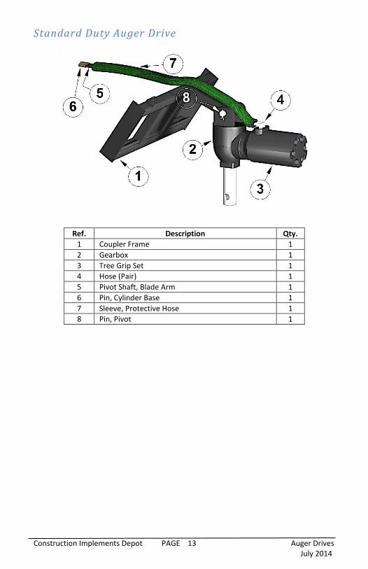
Standard Duty Auger Drive
Ref. Description Qty.
1 Coupler Frame 1
2 Gearbox 1
3 Tree Grip Set 1
4 Hose (Pair) 1
5 Pivot Shaft, Blade Arm 1
6 Pin, Cylinder Base 1
7 Sleeve, Protective Hose 1
8 Pin, Pivot 1

Construction Implements Depot PAGE 14 Auger Drives July 2014
X-treme Auger Drive
Ref. Description Qty.
10 Main Frame & Coupler 1
11
Auger Drive -2” Hex Output Shaft 1
or
Auger Drive – 2 9/16” Round Output Shaft 1
12 Bolt Set (attached bit to auger shaft) 1
13 Hose (Pair) 1
14 Quick Disconnect Coupling Set 1
15 Sleeve, Hose Protector 1
16 Pivot Bracket 1
17 Pin, Pivot 1
18 Pin, Pivot 1
19 Auger Bit – Specify drive type & width A/R
20 Cutter Teeth – Specify auger width 2
21 Point – (If Equipped) - Specify type and length 1
2” Hex Drive
Shown

Construction Implements Depot PAGE 15 Auger Drives July 2014
Decals
1 2
3 4
5
Ref. Description Qty.
1* Decal, (Danger Pinch Points) 2
2* Decal, (Warning, High Pressure Fluid Hazard) 1
3 Decal, Made in the USA 1
4 Decal, Construction Implements Depot 1
5 Decal, Registration & Warranty Info 1
* Replace any worn, torn or missing safety
decals before operating!
Construction Implements Depot PAGE 16 Auger Drives July 2014
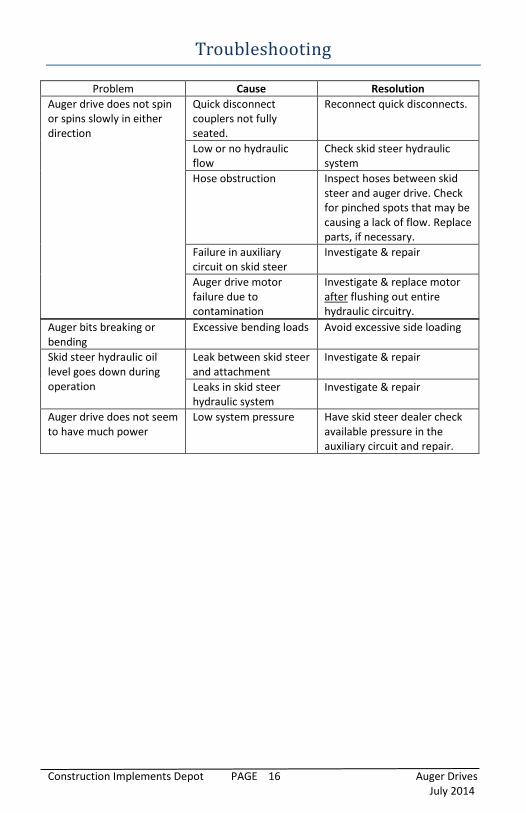
Troubleshooting
Problem Cause Resolution
Auger drive does not spin or spins slowly in either direction
Quick disconnect couplers not fully seated.
Reconnect quick disconnects.
Low or no hydraulic flow
Check skid steer hydraulic system
Hose obstruction Inspect hoses between skid steer and auger drive. Check for pinched spots that may be causing a lack of flow. Replace parts, if necessary.
Failure in auxiliary circuit on skid steer
Investigate & repair
Auger drive motor failure due to contamination
Investigate & replace motor after flushing out entire hydraulic circuitry.
Auger bits breaking or bending
Excessive bending loads Avoid excessive side loading
Skid steer hydraulic oil level goes down during operation
Leak between skid steer and attachment
Investigate & repair
Leaks in skid steer hydraulic system
Investigate & repair
Auger drive does not seem to have much power
Low system pressure Have skid steer dealer check available pressure in the auxiliary circuit and repair.

Construction Implements Depot PAGE 17 Auger Drives July 2014
Specifications
Spec. Model
X-treme Hex Drive X-treme Round Drive Standard Duty Drive
Weight 325 lbs. (147 kg)
325lbs. (147 kg)
304 lbs. (138 kg)
Auger Capacity
3” – 36” (76 – 915 mm)
3” – 18” (76 – 457 mm)
SSL Aux. Hyd. GPM
7-25 GPM (26-94 L/min)
Hyd. Relief Setting
3000 PSI (207 bar)
Warranty 12 months - See complete Warranty Statement for details
X-treme Auger Drive Dimensions
Std. Duty Auger Drive Dimensions

Construction Implements Depot PAGE 18 Auger Drives July 2014
Notes ________________________________________________________________________________________________________________________________________________________________________________________________________________________________________________________________________________________________________________________________________________________________________________________________

Construction Implements Depot PAGE 19 Auger Drives July 2014
Make Every Day
A Safe Day!
Construction Implements Depot PAGE 20 Auger Drives July 2014
1248 N. Main
PO Box 397
Denton, NC 27239
Owner’s Manual
Auger Drives
Website
www.cidattachments.com
For More Information, Contact
Phone: (336)859-2002
Limited Warranty Construction Implements Depot, Inc. products are warranted to be free from defects in workmanship or materials for period of (12) months from initial sale, lease or rental date.
Warranty Exclusions This warranty does not cover normal wear items, including but not limited to, bearings, hoses, ground engaging parts such as, teeth, blades, cutting edges, pilot bits, auger teeth and broom bristles. This warranty does not cover maintenance, service or adjustments. This warranty does not cover damage due to misuse, negligence, accidents, or improper maintenance. This warranty does not cover damage due to improper application, installation, adjustment or setup. This warranty does not cover improper modifications of product. This warranty is void if any components have been disassembled, i.e. pumps, gear boxes, motors. Specially modified attachments built by CID X-treme Attachments to meet your customer's needs shall not be warranted by Construction Implements Depot, Inc. This warranty does not cover replacement parts not supplied by CID, Inc.
Warranty Statement Our obligation under this Limited Warranty shall be solely limited to repairing or replacing any part (see non-covered items) free of charge that, according to our judgment, show evidence of a defect in quality of workmanship or materials for the stated (12) month warranty period. All defective parts must be routed directly to CID, Inc. with freight or delivery charges to be prepaid. This Limited Warranty shall not be interpreted to render CID, Inc. liable for any injury or damage to persons, business or property of any kind nor expenses or losses incurred for labor, supplies, substitute machinery rental, or for any other reason. Repair or replacement parts are subject to the supply conditions at the time of repair or replacements, which may directly affect our ability to obtain material and/or replacements parts. CID, Inc. reserves the right to make improvements in design or changes in specifications at any time without incurring any obligations to owners of previously purchased units. No one but CID, Inc. is allowed to alter, modify or enlarge this warranty nor the exclusions, limitation and reservation at any time.