
X - TKK Tietoliikennelaboratorio · setup/release type signaling ... (Switched Virtual Circuit) IA...
26
X.25 (packet switched data protocol/service/network) • X.25 is a connection-oriented / connectionless protocol suitable for a PSPDN (Packet Switched Public Data Network) • X.25 is ”robust” but requires ”heavy processing” • X.25 involves OSI Layers 1 … 3 in the network • ITU-T (X-series Recommendations)
Transcript of X - TKK Tietoliikennelaboratorio · setup/release type signaling ... (Switched Virtual Circuit) IA...

X.25(packet switched data protocol/service/network)
• X.25 is a connection-oriented / connectionlessprotocol suitable for a PSPDN (Packet SwitchedPublic Data Network)
• X.25 is ”robust” but requires ”heavy processing”• X.25 involves OSI Layers 1 … 3 in the network• ITU-T (X-series Recommendations)

X.25 vs. Frame relay vs. ATM
X.25:♦ Store & forward (L3 processing in network node)♦ Low BW (64 kbit/s, 2 Mbit/s)
FR:♦ Frame relaying (L2 processing in network node)♦ Low to intermediate BW
ATM:♦ Cell relaying (L2 processing in network node)♦ High BW (typically 150 Mbit/s)
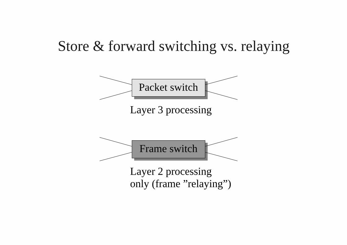
Store & forward switching vs. relaying
Layer 3 processing
Layer 2 processingonly (frame ”relaying”)
Packet switch
Frame switch
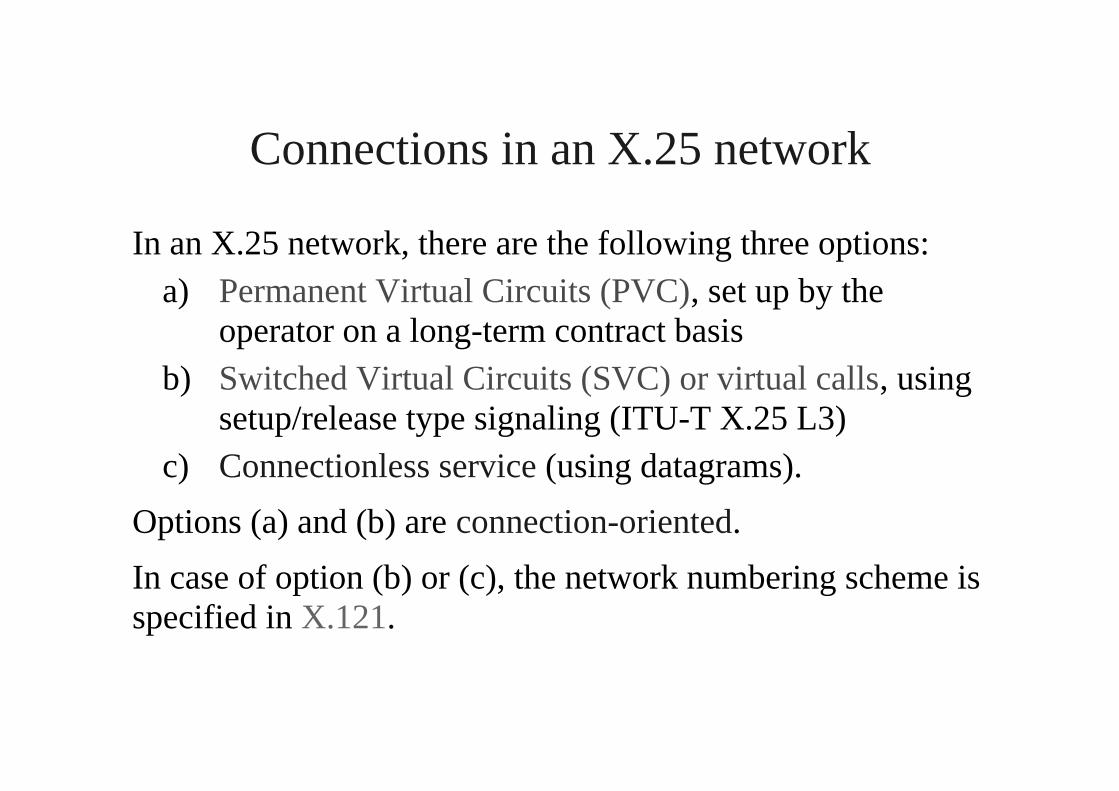
Connections in an X.25 network
In an X.25 network, there are the following three options:a) Permanent Virtual Circuits (PVC), set up by the
operator on a long-term contract basisb) Switched Virtual Circuits (SVC) or virtual calls, using
setup/release type signaling (ITU-T X.25 L3)c) Connectionless service (using datagrams).
Options (a) and (b) are connection-oriented.
In case of option (b) or (c), the network numbering scheme isspecified in X.121.

Characteristics of X.25
• Flow control and error control (frame retransmission)on Layer2 using LAPB
• Flow control and error control (packet retransmission)also on Layer3
• In case of SVC, signaling messages in Layer3
• Physical layer (Layer1): X.21 or X.21bis
• X.25 non-compatible asynchronous terminals can beconnected to a X.25 network via a PAD facility (packetassembly/disassembly facility) specified in X.3

X.25 protocol layers
X.75 inter-network interface
X.25 UNI
X.25 UNIUpper layers
X.25 L3
X.25 L2
Phys. Layer
X.25 L3
X.25 L2
Phys. Layer
X.25 L3
X.25 L2
Phys. Layer
X.25 L3
X.25 L2
Phys. Layer
X.25 L3
X.25 L2
Phys. Layer
Upper layers
X.25 L3
X.25 L2
Phys. Layer
X.25 network
X.25 network

X.25 virtual call example
UNI A packet network(s) UNI B
Call requestIncoming call
Call acceptedCall connected
Data, R=0, S=0Data, R=0, S=0
Data, R=0, S=1

Multiplexing
• 4095 virtual circuits can be used simultaneously over aX.25 interface
• 12 bit virtual circuit number (of local significance)
• individual virtual circuits correspond to applications,processes or terminals
• multiple destinations possible (more than one receiverat the same time) Ø big advantage also of GPRS

Some examples of X.25 packets
Packet type (a sample of > 20 packet types) Service
From DCE to DTE From DTE to DCE VC PVCCall set-up and clearing
Incoming call Call request XCall connected Call accepted X
DataDCE data DTE data X X
Flow control and resetDCE RR DTE RR X XReset indication Reset request X X
VC = virtual call (SVC), PVC = permanent virtual circuit
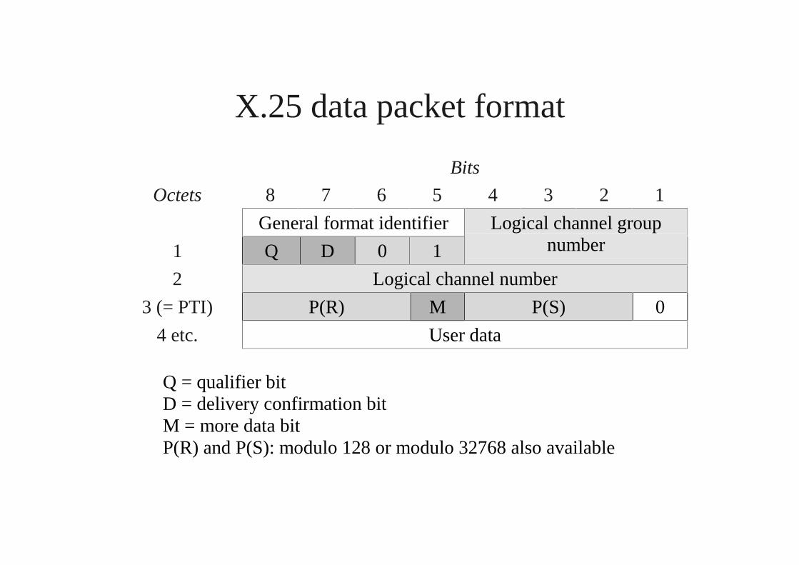
X.25 data packet format
Bits
Octets 8 7 6 5 4 3 2 1
General format identifier
1 Q D 0 1
Logical channel groupnumber
2 Logical channel number
3 (= PTI) P(R) M P(S) 0
4 etc. User data
Q = qualifier bitD = delivery confirmation bitM = more data bitP(R) and P(S): modulo 128 or modulo 32768 also available
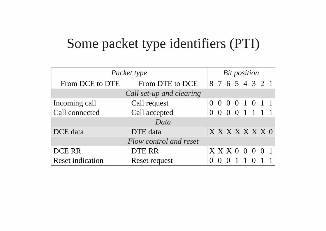
Some packet type identifiers (PTI)
Packet type Bit position
From DCE to DTE From DTE to DCE 8 7 6 5 4 3 2 1Call set-up and clearing
Incoming call Call request 0 0 0 0 1 0 1 1Call connected Call accepted 0 0 0 0 1 1 1 1
DataDCE data DTE data X X X X X X X 0
Flow control and resetDCE RR DTE RR X X X 0 0 0 0 1Reset indication Reset request 0 0 0 1 1 0 1 1
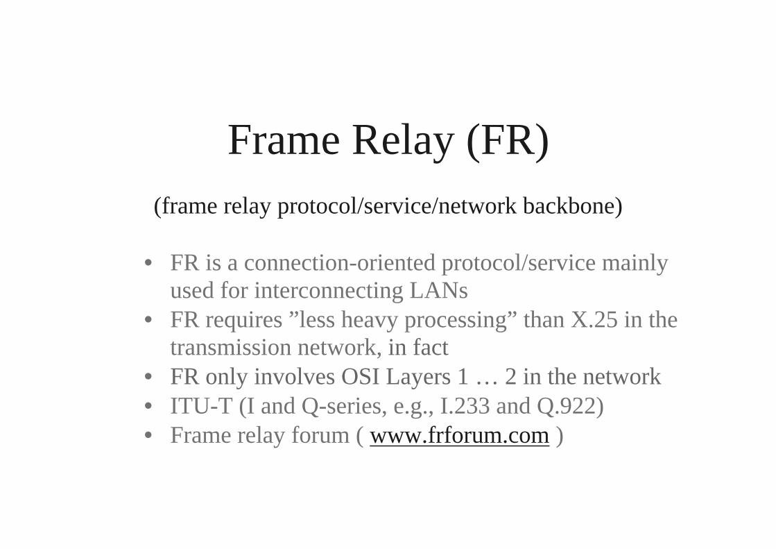
Frame Relay (FR)(frame relay protocol/service/network backbone)
• FR is a connection-oriented protocol/service mainlyused for interconnecting LANs
• FR requires ”less heavy processing” than X.25 in thetransmission network, in fact
• FR only involves OSI Layers 1 … 2 in the network• ITU-T (I and Q-series, e.g., I.233 and Q.922)• Frame relay forum ( www.frforum.com )

FR network connection
Upper layerUpper layer
End-to-end End-to-end
Q.922 core Q.922 core Q.922 core
Physical layer Phy Physical layer
FRAD FRADFR network nodes
Q.922 core
FR relaying within OSI Layer 2
Phy Phy Phy
UNIDLCI 1
Intranetwork interfaceDLCI 2
UNIDLCI 3
Phy Ø FRF.14 (many alternatives)

FR network interface
frame relay access device ≈ frame relay compatible router
Upper layer
Service protocol
Q.922 core Q.922 core Q.922 core
Physical layer Phy Physical layer
FRAD FRADFR network
UNI LAN interfaceUNI
Phy
LAN
LANprotocol
suite

FR Service protocol
• Takes care of end-to-end protocol functions, thusonly present in end devices (e.g., FRADs)
• FRAD = Frame Relay Access Device
• Standardized in ITU-T Q.922 (”Q.922 upper”)
• LAPB (HDLC) -type flow control & error control(retransmission of error-containing frames)
• Flow control (or rather: congestion control) couldmake use of FECN/BECN provided by Q.922 core(some FRADs/routers/bridges can utilize this?)

FR Layer2 protocol (Q.922 core)
• Takes care of some Layer2 functions, and is employedin all FR network nodes
• Standardized in ITU-T Q.922 (”Q.922 core”)
• No LAPB (HDLC) -type flow control & error control inintermediate network nodes!
• ”Core functions” of Q.922 core:- frame assembly /disassembly- discarding of error-containing frames (FCS)- multiplexing and routing at Layer2 (DLCI)- elementary traffic management possible

FR frame format
(fixed bit)
congestion avoidance congestion recovery
Flag FCS Information field Address field Flag
4 DLCI bits 1
FECN BECN DE
6 DLCI bits CR 0
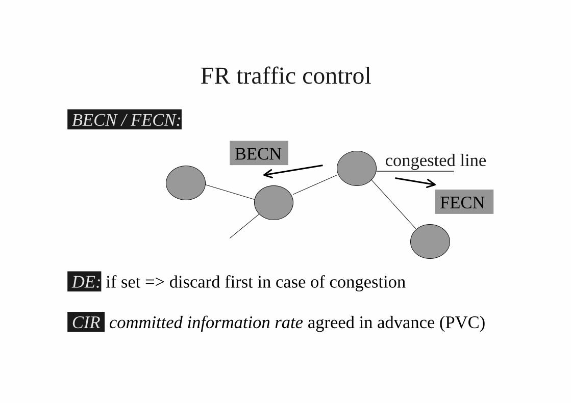
FR traffic control
BECN / FECN:
congested line
DE: if set => discard first in case of congestion
CIR committed information rate agreed in advance (PVC)
BECN
FECN

FR traffic control
Committed information rate:
CIR = Bc / Tc = committed burst size / time interval Tc
Excess information rate:
EIR = Be / Tc = excess burst size / time interval Tc
CIR EIR
send all DE bit set discard all
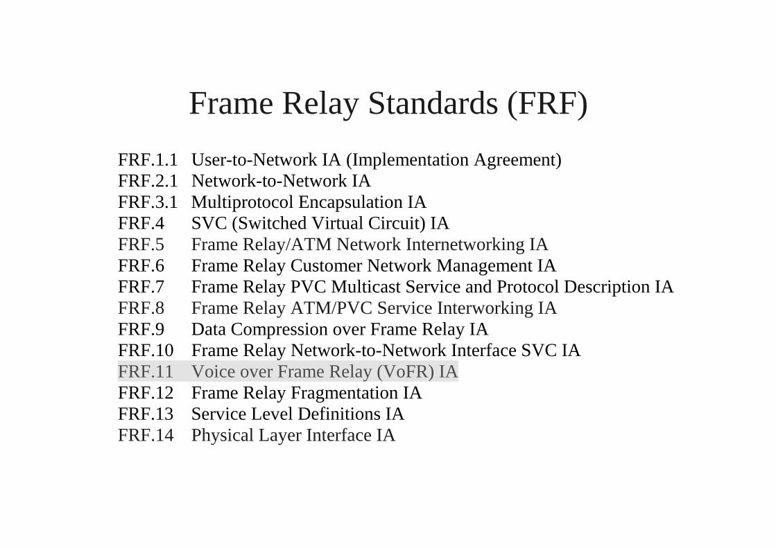
Frame Relay Standards (FRF)
FRF.1.1 User-to-Network IA (Implementation Agreement)FRF.2.1 Network-to-Network IAFRF.3.1 Multiprotocol Encapsulation IAFRF.4 SVC (Switched Virtual Circuit) IAFRF.5 Frame Relay/ATM Network Internetworking IAFRF.6 Frame Relay Customer Network Management IAFRF.7 Frame Relay PVC Multicast Service and Protocol Description IAFRF.8 Frame Relay ATM/PVC Service Interworking IAFRF.9 Data Compression over Frame Relay IAFRF.10 Frame Relay Network-to-Network Interface SVC IAFRF.11 Voice over Frame Relay (VoFR) IAFRF.12 Frame Relay Fragmentation IAFRF.13 Service Level Definitions IAFRF.14 Physical Layer Interface IA

Market success of different technologies - US
$0
$1,000
$2,000
$3,000
$4,000
$5,000
$6,000
$7,000
1996 1997 1998 1999 2000
Private LineX.25SMDSFrameATM

Market success of different technologies – non US
$0
$1,000
$2,000
$3,000
$4,000
$5,000
$6,000
1996 1997 1998 1999 2000
Private LineX.25SMDSFrameATM
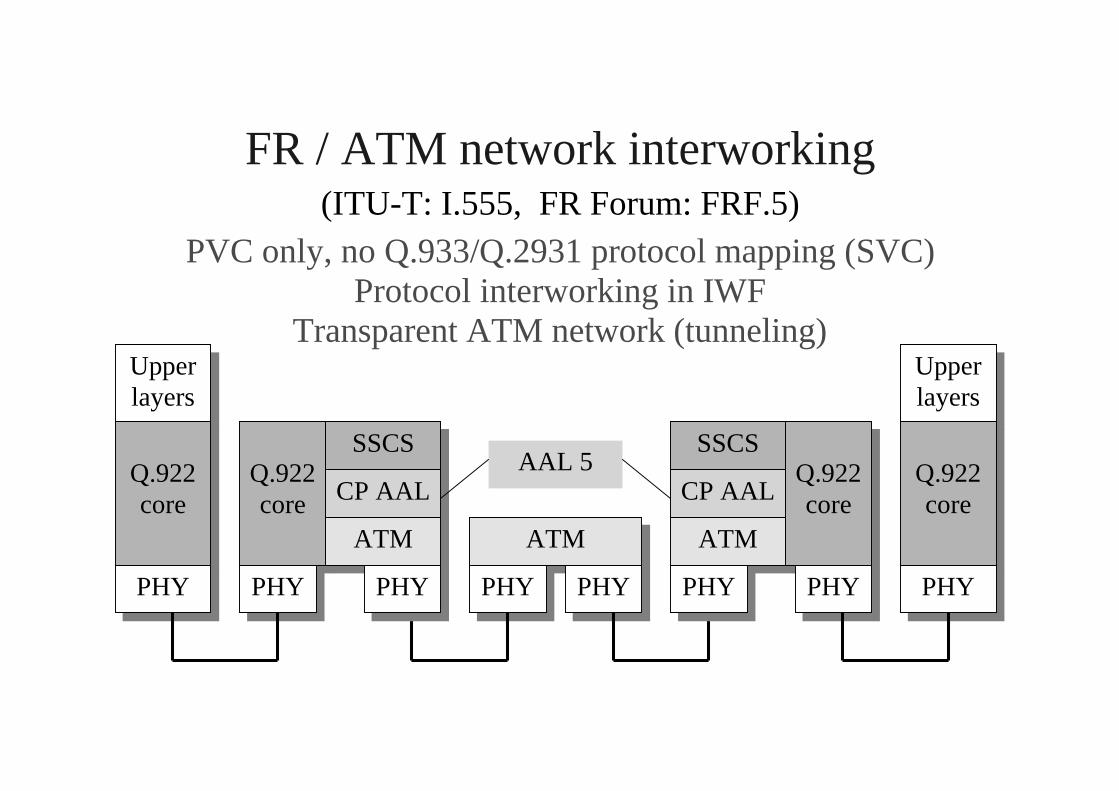
FR / ATM network interworking(ITU-T: I.555, FR Forum: FRF.5)
PVC only, no Q.933/Q.2931 protocol mapping (SVC)Protocol interworking in IWF
Transparent ATM network (tunneling)Upperlayers
Q.922core
Q.922core
SSCS
CP AAL
ATMATM
PHY PHY PHY PHY
Upperlayers
Q.922core
PHY
Q.922core
SSCS
CP AAL
ATM
PHY PHY PHY
AAL 5

FR / ATM service interworking(ITU-T: I.555, FR Forum: FRF.8)
PVC only, no Q.933/Q.2931 protocol mapping (SVC)Protocol translation in IWF at Layer 2 (and higher layers)
(Protocoltranslation)
Upperlayers
Q.922core
Q.922core
ATM
PHY PHY PHY PHY
Upperlayers
Null SSCS
CP AAL
ATM
PHY
Q.922core
PHY PHY
Null SSCS
CP AAL
ATM
PHY
AAL 5

FR / ATM network interworking
AAL 5
T Information field H
8 PAD < 65532 octets
48 octets
FR frame
CS-PDU
SAR-PDU = ATM cell payload PTI+

FR / ATM interworking
Transparent FR frame transmission:♦ Network interworking: yes♦ Service interworking: no
Virtual connection mapping:♦ Network interworking: multiplexing possible♦ Service interworking: VPI/VCI Ø DLCI
Parameter interworking:♦ FECN/BECN Ø PTI, DE Ø CLP♦ CIR, EIR Ø PCR, SCR, MCR, MBS


![Publication [IV] - TKK](https://static.fdocuments.us/doc/165x107/61f2fb971a17171fc95f7b67/publication-iv-tkk.jpg)
