X R. - digital.library.unt.edu/67531/metadc685107/m2/1/high... · platforms on a selected tank pit....
34
DISTRIBUTION SHEET To From Page 1 of 1 J. P. Harris J. R. Bellomy Date 2-15-95 Project Title/Work Order EDT No. 606580 Project W-320 Equipment Removal Systm/D2M49 ECN No. N/A Text Text Only Attach./ EDT/ECN Name MSlN With All Appendix Only Attach. Only . E. Ball . R. Bellomy . R. Crow . P. Harris J. J. Huston T. C. Mackey G. E. McPherson Central Files (2) O.S.T.I. G6-46 X S6-12 X G2-03 X S6-12 S6-12 X S2-03 X S2-41 L8-04 L8-07 X X X X A-6000-13s (01/93) LIEF067
Transcript of X R. - digital.library.unt.edu/67531/metadc685107/m2/1/high... · platforms on a selected tank pit....

DISTRIBUTION SHEET To From Page 1 of 1
J . P. Har r i s J . R . Bellomy Date 2-15-95
Project Title/Work Order EDT No. 606580
Projec t W-320 Equipment Removal Systm/D2M49 ECN No. N/A
Text Text Only Attach./ EDT/ECN Name MSlN With All Appendix Only
Attach. Only
. E . Ball . R. Bellomy
. R . Crow . P. Harr is J . J . Huston T. C . Mackey G . E . McPherson
Central F i l e s (2)
O.S.T.I.
G6-46 X S6-12 X G2-03 X S6-12 S6-12 X S2-03 X S2-41
L8-04
L8-07
X X
X
X
A-6000-13s (01/93) LIEF067
DISCLAIMER
Portions of this document may be illegible in electronic image products. Images are produced from the best available original document.

. Page 1 of
~ . E D T 606580 f E B i895 ENGINEERING DATA TRANSMllTAL *,*3
2. To: (Receiving Organization) 3. From: (Originating Organization)
SST R e t r i e v a l P r o j e c t SST R e t r i e v a l P r o j e c t Eng i neer i ng Engineering 5. Proj./Prog./Dept./Div.: 6. Cog. Engr.:
W320 / Ora. 7F550 I J. R. Bellomv 8. Originator Remarks:
O r i g i n a l I ssue Suppor t ing Document f o r Approval
4. Related EDT No.:
606519
7. Purchase Order No.:
N/A 9. Equip./Conponent No.:
N /A I O . System/Bldg./Facility:
I 241-AY-102, 241-C-106 11. Receiver Remarks: 12. Major Assm. Dwg. No.:
H-2-83726
13. Permit/Permit Application No.:
14. Required Response Date:
ASAP 15. DATA TRANSMITTE
(AI I I (CI I (Dl
(BI DocurnentlDrawing No.
(F)
Impact (E) Ti le or Description of Data Transmitted Level
PROJECT W320 52 INCH EQUIPMENT CONTAINER
REPORT LOAD TEST - TEST
m (G)
Reason for
Trans- mittal
1
16. KEY irnDact Level (FI I Reason for Transmittal (GI I DisDosition (HI & (1)
Origi- Receiv- nator
Dispo- Dispo- t sition sition
1, 2, 3, or 4 (see MRP 5.43)
18. 19. 20. 21. DOE APPROVAL ( i f required) 1 syGf fN L t r . No. [I Approved
J. P. Harris v-5 [I Approved w/comnents Date Authorized Representative Date Cognizant/Project Date [I Disapproved w/comnents
for Receiving Organization Engineer's Manager
J. R. Bellomy Signature of EDT Originator
BD-7400-172-2 (07/91) GEF097
BO-7400-172-1 (07/91)

RELEASE AUTHORIZATION
Document Number: WHC-SD-W320-TRP-002, REV 0
P r o j e c t W320 52- inch Diameter Equipment Con ta ine r Load Tes t - Tes t Report Document Title:
Release Date: 2/22/95
This document was reviewed following the procedures described in WHC-CM-3-4 and is:
APPROVED FOR PUBLIC RELEASE
WHC Information Release Administration Specialist:
February 22, 1995 _y
Kafi M. Broz
TRADEMARK DISCLAIMER. name, trademark, manufacturer, or otherwise, does not necessarily const i tu te or imply i t s endorsement, r e c m n d a t i o n , or favoring by the United States Goverrment or any agency thereof or i t s contractors o r subcontractors.
This report has been reproduced from the best avai lable copy. Avai lable in paper copy and microfiche. Printed i n the United States o f America. from:
Reference herein t o any speci f ic c-rcial product, process, o r service by trade
Available t o the U.S. Department o f Energy and i t s contractors
U.S. Department of Energy O f f i ce of Sc ien t i f i c and Technical Information (OSTI ) P.O. Box 62 Oak Ridge, TN 37831 Telephone: (615) 576-8401
Available t o the pubt ic from: U.S. Department of C-rce National Technical Information Service (NTIS) 5285 Port Royal Road Springfield, VA 22161 Telephone: (703) 487-4650
A-6001-400.2 (09/94) VEF256
SUPPORTING DOCUMENT 1 1. Total Pages 30
2. T i t l e
Project W320 52-inch Diameter Equipment Container Load Test - Test Report
5. Key Words
Project W-320, 49-foot Container, 62-foot
3. Number 4. Rev No.
WHC-SD-W320-TRP-002 0
6. Author
Name: J . R . Bellomy Container, Load Test, Test Report
Organi zat ion/Charge Code 7 F820/D2M49
7. Abstract
This t e s t report summarizes tes t ing ac t iv i t i e s and documents the resu l t s of the load t e s t s performed on-site and of f - s i te t o structural qualify the 52-inch equipment containers designed and fabricated under Project W-320.
8. RELEASE STAMP
A-6400-0'73 (08/94) WEF124

WHC-SD-W320-TRP-002 REVISION 0
PROJECT W-320 52-INCH DIAMETER EQUIPMENT CONTAINER
LOAD TEST TEST REPORT
DISCLAIMER
This report was prepared as an account of work sponsored by an agency of the United States Government. Neither the United States Government nor any agency thereof, nor any of their employees, makes any warranty, express or implied, or assumes any legal liability or responsi- bility for the accuracy, completeness, or usefulness of any information, apparatus, product, or process disclosed, or represents that its use would not infringe privately owned rights. Refer- ence herein to any specific commercial product, process, or service by trade name, trademark, manufacturer, or otherwise does not necessarily constitute or imply its endorsement, recom- mendation, or favoring by the United States Government or any agency thereof. The views and opinions of authors expressed herein do not necessarily state or reflect those of the United States Government or any agency thereof.
J. R. Bellomy February 1995
I
WHC-SD-W320-TRP-002 REVISION 0
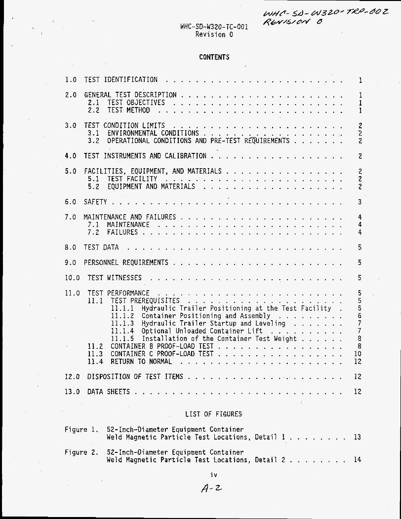
CONTENTS
1.0 INTRODUCTION . . . . . . . . . . . . . . . . . . . . . . . . . . . . 2.0 DESCRIPTION OF TEST . . . . . . . . . . . . . . . . . . . . . . . .
1
2
3.0 TEST METHOD AND TEST EQUIPMENT . . . . . . . . . . . . . . . . . . . 2
4 . 0 TEST RESULTS . . . . . . . . . . . . . . . . . . . . . . . . . . . . 5 . 0 CONCLUSIONS AND RECOMMENDATIONS . . . . . . . . . . . . . . . . . . 6.0 D I S P O S I T I O N OF TEST ITEMS . . . . . . . . . . . . . . . . . . . . . 7.0 REFERENCES . . . . . . . . . . . . . . . . . . . . . . . . . . . . .
3
3
4
5
APPENDICES
A C o m p l e t e d T e s t P r o c e d u r e and Inspec t ion R e c o r d s
ii

WHC-SD-W320-TRP-002 REVISION 0
1.0 INTRODUCTION
Equipment has been designed and fabricated as part of Project W-320 to remotely remove existing contaminated equipment from tanks 241-C-106 and 241- AY-102. (ERS) . The major components of the ERS include the flexible receiver system, the strongback/hydraul ic trailer, the 52-inch diameter equipment containers, the container shot loading system, the emergency container transport trailer, and the 20-ton heavy service gantry cranes. Other miscellaneous components necessary to support operation of the major components during equipment removal activities have also been designed and fabricated.
This equipment is known as the Project W-320 Equipment Removal System
Removal of contaminated equipment from the tanks will be performed by locating the flexible receiver, flexible receiver spool piece assembly, and work platforms on a selected tank pit. high pressure water pump are then positioned near the tank and connected to the flexible receiver. A crane modified with special controls is located adjacent to the tank pit and connected to the flexible receiver and the piece of equipment to be removed. strongback/hydraul ic trailer, and the strongback/hydraul ic trailer positioned within the swing radius o f the crane.
The flexible receiver control trailer and
A 52-inch diameter container is bolted on the
Once all equipment has been installed and operational checks performed, equipment removal activities are initiated. The 52-inch equipment container is raised to the vertical position with the strongback/hydraulic trailer. crane is then used to pull the piece of contaminated equipment from the tank pit and through the flexible receiver. As the equipment is removed, the flexible receiver maintains tank confinement, decontaminates the equipment with a high pressure water spray, performs a radiological assessment (gamma assay) and applies a bag to the equipment. When the piece of equipment has been fully extracted and is at an established height, the flexible receiver bag is remotely tied and sheared. of equipment at the flexible receiver leak containment bag assembly, where a secondary bag is remotely applied on the bottom end.
The
The crane then repositions the bagged piece
Following application of the leak containment bag, the bagged piece o f equipment is raised and centered above the container with the crane. The equipment is then lowered into the container. Once the equipment is within the container, the strongback/hydraul ic trailer is used to reposition the container from the vertical to the horizontal position. The crane is then disconnected and end caps are installed on the container.
After the container has been closed, the strongback/hydraul ic trailer and container are located underneath the shot loading platform. The shot loading system is then used to place shot within the annulus area of the container as required for radiological shielding during transportation and storage. Equipment removal activities are concl uded by transporting the 1 oaded container (using the strongbacklhydraul ic trailer or the emergency container transport trailer) to the onsite storage facility where the gantry cranes are used for offloading.
1
WHC-SD-W320-TRP-002 REVISION 0
A total of there 52-inch diameter equipment containers have been designed and fabricated as part of Project W-320; (Containers A and B) and 1 container 62-foot long (Container C). The 49-fOOt containers were specifically designed to support equipment removal activities at tank 241-C-106 while the 62-foot long container was designed to support equipment removal activities at tank 241-AY-102.
2 identical containers 49-fOOt long
As part of the design verification associated with the 52-inch equipment containers, each of the containers were subjected to a load test. was shipped with the strongback to the hydraulic trailer manufacturer and was successfully load tested during the factory acceptance testing of the hydraulic trailer. the delivery of the hydraulic trailer.
This test report summarizes the load testing performed to structurally qualify the 52-inch diameter equipment containers for their intended application. Test procedures and test results are included and/or discussed for all three of the equipment containers (A, 6, and C).
Container A
Container B and Container C were tested onsite following
2.0 DESCRIPTION OF TEST
The load test performed on Container A was conducted at the AMRO Fabricating Corporations facility in South El Monte, California. The load test was performed by AMRO on July 25, 1994 as part of the Factory Acceptance Test of the strongback/hydraul i c trai 1 er. hydraulic trailer factory acceptance test procedure and was witnessed by members o f Westinghouse Hanford Company (WHC) Projects, WHC Engineering Analysis and WHC Quality Assurance.
Load testing of Containers B and C was conducted at the ICF Kaiser Hanford Company (ICF KH) fabrication facility in the 3000 Area. fol 1 owing the procedure i ncl uded i n WHC-SD-W320-001 (Bel 1 omy 1994) . ICF KH Construction forces performed the test under the direction of WHC Projects. Testing was witnessed by members of WHC Engineering Analysis and WHC Quality Assurance.
Testing foll owed the AMRO prepared
Testing was performed
3.0 TEST METHOD AND TEST EQUIPMENT
All three of the containers were load tested using the strongback/hydraulic trailer and the container test weight assembly (H-2-83735). Each container was located on the strongback/hydraulic trailer and bolted into position in accordance with assembly drawing H-2-83726. onto the top or forward end of each container and test weight plates were placed on the test weight holder and pinned into position.
Plates were added to the test weight assembly as required to achieve the desired weight required for testing. exceeding 125 percent of the heaviest piece of equipment planned to be removed under Project W-320 as a minimum.
The test weight holder was bolted
Each container was tested with a weight
After the installation o f the test weight assembly, the containers were cycled from the horizontal position t o vertical position and back to the horizontal position using the strongback/hydraul ic trailer. returned to the horizontal position, the test weight assembly was removed from
Once a container was
2

WHC-SD-W320-TRP-002 REVISION 0
the container and the container removed from the strongback. Following removal of the container from the strongback, a complete visual inspection of the container was performed to verify that the structural integrity of the container had not been compromised. Magnetic Particle testing was also performed on the inside and outside face of both vertical welds at each of the four attachment plates (a1 1 containers).
Container A was the first container fabricated and was used for qualification of the container, strongback, and hydraulic trailer designs. Initial testing o f the strongback/hydraulic trailer was performed by lifting Container A and the test weight assembly with all 6 plates attached (14,000 pounds). load (14,000 pounds) represented the loa’ding identified on the strongback/hydraulic trailer load chart [reference WHC-SD-W320-DA-00lY page A- 46 (Mackey 1994)] plus an additional 25 percent. After this initial qualification, 2,000 pounds were removed from the test weight assembly. The testing of the trailer hydraulic system was then continued using Container A and the test weight assembly with 5 plates attached (12,000 pounds) which represented loading per the referenced load chart.
This
Containers-B and C were both tested with the test weight assembly with 1 plate attached (4500 pounds). This weight (4,500 pounds) represented 125 percent of the weight of the heaviest piece of equipment planned to be removed under Project W-320.
4.0 TEST RESULTS
The visual inspections were acceptable and did not identify any signs of damage to any area of the containers as a result of the load tests.
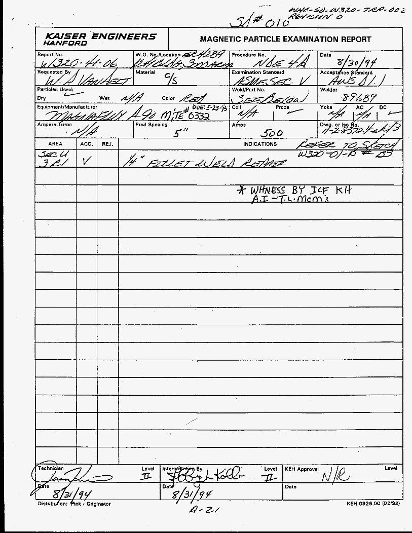
The magnetic particle examinations did not reveal any weld defects induced as a result of the load test. One indication (3/8 inch slag inclusion) was identified on one of the inside welds of Container B. Research of the fabrication records indicated that the final magnetic particle examination of the inside welds had been overlooked during fabrication, which accounted for the presence o f the defect. The slag inclusion was removed and the weld repaired. Following repair, a magnetic particle examination was performed on the weld repair area and found acceptable.
The completed test procedure and inspection records for the container load tests performed on site are included as Appendix A. procedure and inspection records for testing performed by AMRO Fabricating are included in the Certified Vendor Information (CVI) File for the Project W-320 Hydraulic Trailer, CVI file # 22642
The completed test
5.0 CONCLUSIONS AND RECOMMENDATIONS
The container load tests were all determined successful. The testing demonstrates that the containers are structurally sound and will function as designed when used during equipment removal activities. No further load test i ng i s required or recommended.
3

WHC-SD-W320-TRP-002 REVISION 0
6.0 DISPOSITION OF TEST ITEMS
All t es t ing was performed i n accordance with the approved tes t procedure. Containers will be stored onsi te u n t i l needed fo r tes t ing and t ra ining.
4

WHC-SD-W320-TRP-002 REVISION 0
7.0 REFERENCES
Bellomy, J. R . , 1994, P r o j e c t W-320 52-inch diameter Equipment Conta iner Load Test, WHC-SD-W320-TC-001, Revis ion 0, Westinghouse Hanford Company, R i c h l and, Washington.
Mackey, T. C., 1994, S t r u c t u r a l Ana lys is o f t h e Equipment Removal System For Tanks 241-C-106 and 241-AY-102, WHC-SD-W320-DA-001, Rev is ion 0, Westinghouse Hanford Company, R ich l and, Washington.
5

WHC-SD-W320-TRP-002 R E V I S I O N 0
APPENDIX A:
Completed Test Procedure and Inspection Records

PROJECT W-320 52-INCH-DIAMETER EQUIPNENT CONTAINER
LOAD TEST
J . R . Bellomy August 1994
A- 1
1.0
2.0
3.0
4.0
5.0
6.0
7 . 0
8.0
9.0
10.0
11 . 0
12.0
13.0
WHC-SD-W320-TC-001 Revision 0
CONTENTS
TEST IDENTIFICATION . . . . . . . . . . . . . . . . . . . . . . . . 1
GENERAL TEST DESCRIPTION . . . . . . . . . . . . . . . . . . . . . . 1 2.1 TEST OBJECTIVES . . . . . . . . . . . . . . . . . . . . . . . 1 2.2 TEST METHOD . . . . . . . . . . . . . . . . . . . . . . . . . 1
TEST CONDITION LIMITS . . . . . . . . . . . . . . . . . . . . . . . 3.1 ENVIRONMENTAL CONDITIONS . . . . . . . . . . . . . . . . . . 3.2 OPERATIONAL CONDITIONS AND PRE-TEST RE~UIREMENTS . . . . . . .
TEST INSTRUMENTS AND CALIBRATION . . . . . . . . . . . . . . . . . . FACILITIES. EQUIPMENT. AND MATERIALS . . . . . . . . . . . . . . . . 5.1 TEST FACILITY . . . . . . . . . . . . . . . . . . . . . . . . 5.2 EQUIPMENT AND MATERIALS . . . . . . . . . . . . . . . . . . .
SAFETY . . . . . . . . . . . . . . . . . . . . . . . . . . . . . . .
2 '2 2
2
2 2 2
3
MAINTENANCE AND FAILURES . . . . . . . . . . . . . . . . . . . . . . 4 7 . 1 MAINTENANCE . . . . . . . . . . . . . . . . . . . . . . . . . 4 7 . 2 FAILURES . . . . . . . . . . . . . . . . . . . . . . . . . . . 4
TEST DATA . . . . . . . . . . . . . . . . . . . . . . . . . . . . . PERSONNEL REQUIREMENTS . . . . . . . . . . . . . . . . . . . . . . . TEST WITNESSES . . . . . . . . . . . . . . . . . . . . . . . . . .
5
5
5
TEST PERFORMANCE . . . . . . . . . . . . . . . . . . . . . . . . . 5 11.1 TEST PREREQUISITES . . . . . . . . . . . . . . . . . . . . . 5
11.1.1 Hydraulic Trailer Positioning at the Test Facility . 5 11.1.2 Container Positioning and Assembly . . . . . . . . . 6 11.1.3 Hydraulic Trailer Startup and Leveling . . . . . . . 7 11.1.4 Optional Unloaded Container Lift . . . . . . . . . . 7 11.1.5 Installation o f the Container Test Weight . . . . . . 8
11.2 CONTAINER B PROOF-LOAD TEST . . . . . . . . . . . . . . . . . 8 11.3 CONTAINER C PROOF-LOAD TEST . . . . . . . . . . . . . . . . . 10 11.4 RETURN TO NORMAL . . . . . . . . . . . . . . . . . . . . . . 12
DISPOSITION OF TEST ITEMS . . . . . . . . . . . . . . . . . . . . . . . 12
DATA SHEETS . . . . . . . . . . . . . . . . . . . . . . . . . . . . 12
LIST OF FIGURES-
Figure 1 . 52-Inch-Di ameter Equipment Container Weld Magnetic Particle Test Locations. Detail 1 . . . . . .
Figure 2 . 52-Inch-Diameter Equipment Container Weld Magnetic Particle Test Locations. Detail 2 . . . . . .
iv
A - z
13
. 14

PROJECT W-320 52-INCH-DIAMETER EQUIPMENT CONTAINER
LOAD TEST
1.0 TEST IDENTIFICATION
This test procedure establishes the requirements for the ons te load testing of the 52-in.-diameter equipment containers fabricated for use in equipment removal activities associated with Projgct W-320. A tot 1 of three 52-in.-diameter equipment containers have been fabricated under Project W-320: two are identical containers 49 ft in length (containers A and B; see drawing H-2-83724); the third container'is 62 ft in length (container C; see drawing H-2-83728).
This test procedure i ncl udes requi rements for 1 oad testing only containers B and C. factory acceptance test for the hydraulic trailer performed by the manufacturer of the hydraulic trailer. is required before field use.
Container A was load tested successfully as part of the
No further load testing of container A
This test procedure follows the format and content guidelines recommended for test procedures as prescribed in WHC-IP-1026, Engineering Practice Guidelines, Appendix K, "Test Plans, Specifications, Procedures and Reports. "
2.0 GENERAL TEST DESCRIPTION
2.1 TEST OBJECTIVES
The objective o f this test is to verify the structural integrity of the Project W-320 52-in.-diameter equipment containers by cycling the containers from the horizontal to the vertical position in the loaded condition. Successful completion of this test will demonstrate that each container is structurally adequate to perform its intended design function.
2.2 TEST METHOD
The container load test will be performed by installing each container on the strongbacklhydraul ic trailer, attaching a 4,500-lb test weight to the flanged end of the container, raising the container to the full vertical position, then returning it to the horizontal position. Following vertical cycling, the container will be removed from the hydraulic trailer and visually inspected for structural integrity. Magnetic particle inspection then will be performed on the container welds at the points where the container is attached to the strongback.
Containers B and C will be load tested. The test sequence is identical for both containers.
Note: The 4,500-lb test weight exceeds 125 percent o f the weight of the heaviest piece of equipment planned for removal as part of Project W-320.
1
4 -3

&!!/-54 - w3zo - 7 H - d# 2 &%V72SOM d WHC-SD-W320-TC-00 1
Revision 0
3.0 TEST CONDITION LIMITS
The following pre-test requirements shall be met or shall ex is t before tes t ing begins.
3.1 ENVIRONMENTAL CONDITIONS
Testing shall be performed only on a calm day w i t h wind conditions not expected t o exceed 15 m i / h (weather forecasts may-be obtained by call ing t h e . PNL weather forecaster a t 373-2716). Testing shall cease and the container shall be returned t o the horizontal position, i f in the opinion of the Test Director, wind conditions might affect , a t any time, the safe operation of the hydraul i c t r a i 1 er .
3.2 OPERATIONAL CONDITIONS AND PRE-TEST REQUIREdENTS
Before tes t ing begins, the installati-on of the container on the strongback and the t e s t weight on the container shall be verified. hydraulic t r a i l e r shall be in a level condition and a l l operational checks shall have been performed successfully.
The
The hydraulic t r a i l e r shall be operated only under the d i rec t supervision of the Test Director. a l l operational character is t ics o f the hydraulic and e lectr ical systems of the hydraulic t r a i l e r and shall have had experience i n operating the t r a i l e r .
The Test Director shall be familiar w i t h
4.0 TEST INSTRUMENTS AND CALIBRATION
No special t e s t equipment or equipment calibration requirements are necessary t o suppor t performance o f the t e s t .
5.0 FACILITIES, EQUIPMENT, AND MATERIALS
5.1 TEST FACILITY
Testing may be performed a t any location suitable for the safe operation of the hydraulic t r a i l e r . The t r a i l e r shall be positioned on a level , hard- packed gravel, asphalt, or concrete surface.
5.2 EQUIPHENT AND MATERIALS
The fol 1 owing equipment and materi a1 s shall be avai 1 ab7 e t o support tes t ing :
The W-320 strongbacklhydraul i c t r a i 1 e r 52-in. by 49-ft container - Container B (drawing H-2-83724)
2

52-in. by 62-ft container - Container C (drawing H-2-83728) Container test-weight assembly (drawing H-2-83735) %-in . -thick plywood container test-weight gasket Bo1 ting - container to strongb.ack container-attachment assembly -
- Heavy hex nuts, 15-6 UNC-2B, ASTM 194 GR 2H (total of 8 required) - Flat washers, l\-in.-diameter ASTM F436 (total o f 16 required) .
Bo1 ting - strongback container-attachment assembly to strongback - Hex head bolts, 1-8 UNC-2A by 3+in.-long ASTM A325 (total of 32
required) - Hex head bolts, 1-8 UNC-2A X 3+in.-long, ASTM A325 (total o f 16
required) - Flat Washers, l-in.-diameter ASTM F436 (total of 48 required)
Hex head bolts, 15-6 UNC-2A by 5%-in.-long ASTM A325, Type 1, 2k-in. thread (total of 8 required)
Bo1 ting - Test-weight assembly to container - Hex head bolts, 1-8 UNC-2A by 3+-in.-long ASTM A325 (total o f 32
- Flat Washers, 1-in.-diameter ASTM F436 (total o f 32 required) - Plated oval ring hitch pin, %-in.-diameter by 4%-in.-long with
Magnet i c part i cl e inspection equi pment
Required)
cotter pin
Two mobile boom cranes and rigging necessary to lift and position container test weight assembly and 52-in.-diameter equipment containers.
6.0 SAFETY
The following mandatory safety requirements are to be observed at a l l times during testing.
(ICF KH) safety practices and standards of conduct shall be adhered to at all times.
0 Westinghouse Hanford Company (WHC) and/or ICF Kaiser Hanford Company
0 A test zone shall be established and roped off around the perimeter of the hydraulic trailer before testing begins. The test zone boundaries shall be established by the Test Director and the ICF KH Construction Manager. No personnel shall be allowed within the test zone at any time during the operation o f the trailer hydraulic system without the authorization o f the test director.
0 Hard hats, substantial footwear, safety glasses, and gloves (as required) shall be worn by all personnel within the test zone.
3
A - 5

&J4fl-4&Li/3Zt7-7@-- 00 z &&/c/v 6 WHC-SD-W320-TC-001
Revision 0
The Test Director shall be present at all times during operation of the hydraulic trailer and at any time the container is lifted from the horizontal position.
e Safety rails shall remain in position on the hydraulic trailer at all times.
e Personnel performing bo1 ti ng operations or working on the hydraul i c trailer deck in the strongback area or on the rear of the hydraulic trailer shall wear and use safety belts if scaffolding is not present.
At the end of each shift and at any time thTTest Director is not present, the container shall be in the horizontal position (all pressure shall be relieved from the main telescoping hydraulic cylinder), and electrical power to the hydraulic trailer shall be disconnected.
Note: Outrigger cylinders may remain loaded at the end of each shift and in the absence of the Test Director. Internal counterbalance valves are included in each of the outrigger hydraulic cylinders that l o c k the cylinders in position. The electrical system must be energized and a hydraulic pump must be in operation to load or unload the outrigger cy1 i nders .
* The container test procedure as detailed in Section 11.0 shall be followed as detailed in the written sequence. shall a procedural step or verification be bypassed.
Under no circumstances
No adjustment shall be made to any of the hydraulic trailer hydraulic components without the authorization of the Test Director.
7.0 MAINTENANCE AND FAILURES
7.1 MAINTENANCE
Should the hydraulic trailer not be functioning or performing properly, the test shall cease, and adjustments/maintenance shall be performed as required. All maintenance and adjustments t o the trailer hydraulic and _electrical system shall be under the direct supervision of the Test Director.
7.2 FAILURES
Any observable evidence of an unsafe condition or failure of any component of the hydraulic trailer, the container, or the container test-weight assembly shall be brought immediately to the attention o f the Test Director. The Test Director shall evaluate the condition and shall discontinue testing and return the container to the horizontal position in a safe manner, if the condition warrants. required corrective actions have been performed.
Testing may resume only after any
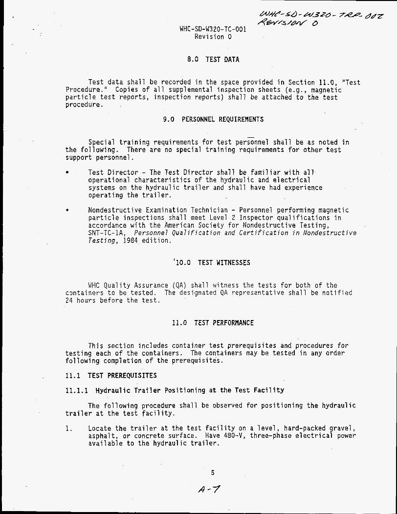
8.0 TEST DATA
Test data shall be recorded in the space provided in Section 11.0, "Test Procedure." Copies of all supplemental inspection sheets (e.g., magnetic particle test reports, inspection reports) shall be attached to the test procedure.
9.0 PERSONNEL REQUIREHENTS
Special training requirements for test personnel shall be as noted in the following. support personnel.
There are no special training requirements for other test
0 Test Director - The Test Director shall be familiar with all operational characteristics of the hydraulic and electrical systems on the hydraulic trailer and shall have had experience operating the trailer.
0 Nondestructive Examination Technician - Personnel performing magnetic particle inspections shall meet Level 2 Inspector qualifications in accordance with the American Society f o r Nondestructive Testing, SNT-TC-lA, Personnel Qualification and Certification in Nondestructive Testing, 1984 edition.
'10.0 TEST WITNESSES
WHC Quality Assurance (QA) shall witness the tests for both of the containers to be tested. 24 hours before the test.
The designated QA representative shall be notified
11.0 TEST PERFORMANCE
This section includes container test prerequisites and procedures for The containers may be tested in any order testing each of the containers.
following completion of the prerequisites.
11.1 TEST PREREQUISITES
11.1.1 Hydraulic Trailer Positioning a t the Test Facility
The following procedure shall be observed for positioning the hydraulic trailer at the test facility.
1. Locate the trailer at the test facility on a level, hard-packed gravel, asphalt, or concrete surface. Have 480-V, three-phase electrical power available to the hydraulic trailer.
5
A - 7

2.
3.
4.
5 .
6.
7 .
8.
9.
Disconnect the t rac tor from the hydraulic t r a i l e r i n accordance w i t h the hydraul i c t r a i 1 e r operations manual . Remove a l l t r a i l e r packing materials installed by the t r a i l e r manufacturer.
Ensure t h a t a l l handrail sections are installed around the front perimeter of the hydraulic t r a i l e r . b
Note: correspond t o position markings on the t r a i l e r side r a i l .
Handrails are marked with unique identification numbers tha t
In s t a l l portable steps or secure a ladder a t one'or b o t h handrail gate posit ions t o provide access t o the forward deck of the hydraulic t r a i 1 e r .
Ensure tha t the forward container s u p p o r t located on the t r a i l e r deck i s located properly and bolted into position for tes t ing o f the f i r s t container.
Note: (container B ) is t o be tested f i r s t . (container C ) i s t o be tested f i r s t , remove the center support from the t r a i l e r deck and s tore i t a t an appropriate location. ident ical and are interchangeable.
Bo th supports may be i n position i f the 49-ft container If the 62-ft container
Both supports are
Inspect the strongback/hydraulic t r a i l e r surface and remove any loose materi a1 s , bo1 t i ng, o r mi scell aneous i terns.
Remove outrigger cylinder retainer brackets a t each of the s ix outriggers and s tore in the control pendant box.
Ins ta l l sand shoes (outrigger pads) on t h e s i x outrigger cylinders
Note: outrigger. fo r outrigger ident i f icat ion. The t o p of each outrigger i s also marked w i t h the outrigger identification number. However, when the outriggers a re re t racted, the identification marking i s concealed.
10. Remove bolting from the container strongback-attachment assembly; stake threads on removed bolts or paint bolts t o identify them as used.
The sand shoes are marked t o correspond w i t h t h e i r mating Refer t o the placard a t the main hydraulic control console
11.1.2 Container Positioning and Assembly
Assembly, 'I as required during assembly operations.
1.
Refer t o drawings H-2-83726, " 4 9 ' - 62 ' X 52" Diameter Transport
L i f t the selected container and position i n t o the strongback and forward container support.
6
4-6
W4P-S.4- w320 - 7e- do 2 R M 2 W U . D
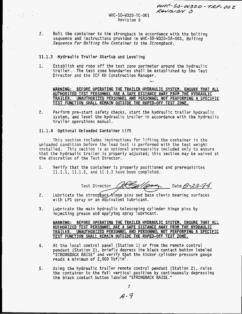
WHC-SD-W320-TC-001 Revision 0
2. Bolt the container t o the strongback in accordance with the bolting sequence and instructions provided in WHC-SD-W320-DA-003, Bolting Sequence for Bolting the Container to the Strongback.
11.1.3 Hydraulic Trailer S t a r t u p and Leveling
1. Establish and rope off the t e s t zone perimeter around the hydraulic t r a i l e r . The t e s t zone boundaries shall be established by the Test Director and the ICF KH Construction Manager.
WARNING: BEFORE OPERATING THE TRAILER HYDRAULIC SYSTEM, ENSURE THAT ALL AUTHORIZED TEST PERSONNEL ARE A SAFE DISTANCE AWAY FROM THE HYDRAULIC TRAILER. UNAUTHORIZED PERSONNEL AND PERSONNEL NOT PERFORMING A SPECIFIC TEST FUNCTION SHALL REMAIN OUTSIDE THE ROPED-OFF TEST ZONE.
2. Perform pre-start safety checks, s t a r t the hydraulic t r a i l e r hydraulic system, and level t h e hydraulic t r a i l e r in accordance with the hydraulic t r a i 1 e r operations manual.
11.1.4 Optional Unloaded Container L i f t
This section includes instructions for l i f t i n g the container i n the unloaded condition before the load t e s t i s performed with the t e s t weight ins ta l led . This section i s an optional prerequisite included only t o ensure t h a t the hydraulic t r a i l e r i s properly adjusted; t h i s section may be waived a t the discret ion of the Test Director.
1.
2.
3.
4.
5 .
Verify t h a t the container i s properly positioned and prerequisites 11.1.1, 11.1.2, and 11.1.3 have been completed.
Test Director Date H-23-94 L u b r with
Lubr
cate the s t r o n g w n g e pins and base clevis bearing surfaces LPS spray or an equivalent lubricant.
cate the main hydraulic telescoping cy1 inder hinge pins by inject ing grease and applying spray 1 ubricant.
WARNING: BEFORE OPERATING THE TRAILER HYDRAULIC SYSTEM. ENSURE THAT ALL AUTHORIZED TEST PERSONNEL ARE A SAFE DISTANCE AWAY FROM THE HYDRAULIC TRAILER. UNAUTHORIZED PERSONNEL AND PERSONNEL NOT PERFORMING A SPECIFIC TEST FUNCTION SHALL REMAIN OUTSIDE THE ROPED-OFF TEST ZONE.
A t the local control panel (Station 1) or from the remote control pendant ( S t a t i o n 2) , briefly depress the black contact b u t t o n labeled "STRONGBACK RAISE" and verify t g a t the kicker cylinder pressure gauge reads a minimum o f 2,000 lbf / in . Using the hydraulic t r a i l e r remote control pendant (Station Z), ra i se the container t o the ful l vertical position by continuously depressing the bl ack contact but ton 1 abel ed "STRONGBACK RAISE. I'
7
W ~ ~ - 5-d - w32.0 - 7Rp- dUZ &W/S/dn/ 0
WHC-SD-W320-TC-001 Revision 0
Note: Raising the strongback/container will take approximately 15 min. When the container/strongback reaches the fu l l vertical position (90 degrees) each of the rear kicker cylinders will contact a hard stop and t r i p a l imit switch. Once the l imit switch tr ips, a solenoid valve automatically actuates and diverts f luid flow from the main telescoping hydraulic cylinder t o the hydraulic f luid reservoir.
6. Using the hydraulic t r a i l e r remote control pendant (Station 2) , lower the container t o the horizontal position by continuously depressing the black contact b u t t o n 1 abeled "STRONGBACK LOWER. I'
Ensure t h a t the container and the strongback are properly seated a t t h e i r forward support positions. .
7.
8. Shut down the hydraulic system and de-energize the electr ical system in accordance w i t h the t r a i 1 e r operations manual.
Note: position or may be retracted a t the discretion of the t e s t director .
The hydraulic t r a i l e r outriggers may remain i n the deployed
11.1.5 Ins ta l la t ion of the Container Test Weight
Refer t o drawing H-2-83735, "Test Weight Arrangement," as required during assembly operations.
1.
2.
3 .
4 .
11.2
1.
2.
Position the container t e s t weight - test-weight holder (baseplate) a t the forward end of the container. test-weight assembly shall be in accordance with drawing H-2-83735.
Handling and rigging of the
Position the %-in. plywood test-weight gasket between the test-weight holder and the container f l ange.
B o l t the container t e s t weight t o the container flange using 16, 1-8 UNC-2A by 3+in.-long ASTM A325 heavy hex bolts and 1-in.-diameter ASTM F436 f l a t washers. i s the tightness resulting from the ful l effor t of a man using an ordinary spud wrench).
Bolts are t o be snug t igh t only ("Snug t i gh t "
Ins ta l l one (1) t e s t plate on the container test-weight holder and pin into place using the 34-in.-diameter by 434-in.-long plated oval r i n g hitch p i n and co t te r pin.
CONTAINER B PROOF-LOAD TEST
Verify tha t container B i s properly positioned and that a l l t e s t prerequisites have been completed.
Date /?-Jc-!% Lubricate the s t r o n g bearing surfaces w i t h LPS spray or an equivalent lubricant.
8
A -/D
3.
4 .
5 .
6.
7.
8.
9.
10.
11.
12.
Lubricate the main hydraulic telescoping cylinder hinge pins by injecting grease and applying spray lubricant.
WARNING: BEFORE OPERATING THE TRAILER HYDRAULIC SYSTEM. ENSURE THAT ALL AUTHORIZED TEST PERSONNEL ARE A SAFE DISTANCE AWAY FROM THE HYDRAULIC TRAILER. UNAUTHORIZED PERSONNEL AND PERSONNEL NOT PERFORMING A SPECIFIC TEST FUNCTION SHALL REMAIN OUTSIDE THE ROPED-OFF TEST ZONE.
At the local control panel (Station 1) or from the remote control pendant (Station Z), briefly depress the black contact button labeled . "STRONGBACK RAISE" and verify tkat the kicker cy1 inder pressure gauge reads a minimum of 2,000 lbf/in . Using the hydraulic trailer remote control pendant (Station Z), raise the container to the full vertical position by continuously depressing the black contact button 1 abel ed "STRONGBACK RAISE. "
Note: Raising the strongback/container will take approximately 15 min. When the container/strongback reaches the full vertical position (90 degrees), each of the rear kicker cylinders will contact a hard stop and trip a limit switch. Once the limit switch trips, a solenoid valve automatically actuates and diverts fluid flow from the main telescoping hydraulic cylinder to the hydraulic fluid reservoir.
Using the hydraulic trailer remote control pendant (Station Z), lower the container to the horizontal position by continuously depressing the bl ack contact button 1 abel ed "STRONGBACK LOWER. I'
Ensure that the container and the strongback are properly seated at their forward support positions.
Shut down the hydraulic system and de-energize the electrical system in accordance with the hydraulic trailer operations manual.
Note: position or may be retracted at the discretion of the Test Director.
Remove the container test-weight assembly from the container and mark the bolting (bolts and nuts) that is removed in such a way that it can be identified as used.
Unbolt the container from the strongback container-attachment assembly and mark the bolting that i s removed in such a way that it can be identified as used.
The hydraulic trailer outriggers may remain in the deployed
Loosen the strongback container attachment assembly bo7 ting and reposition the attachment assembly as necessary to facil i tate removal the container. Mark the bolting in such.a way that it can be identif as used.
of ed
Remove the container from the strongback/hydraul ic trailer and place on a minimum of two container supports.
RWZ5/6w/ D WHC-SD-W320-TC-001
Revision 0
13.
14.
15.
11.3
1.
2.
3 .
4 .
5.
Remove paint from the two vertical welds a t each attachment plate (Figures 1 and 2 ) on the container ( total of four plates) and perform a magnetic par t ic le inspection of the welds.
Visually inspect the container and verify by signing in the space provided below t h a t the structural integrity o f the container was maintained and no signs o f damage occurred as a resu l t of tes t ing .
Note: Visual inspection shall be the responsibility of the WHC QA representative and the Project Cognizant Engineer and/or Structural Engineer.
QA Representative *. W320 Engine Date 8-25-94
When the t e s t of contai leted, the Test Director shall sign below, verifying t h a t the load t e s t for container B i s complete and t ha t resu l t s have been accepted.
Test Direc
QA Represe
CONTAINER C PROOF-LOAD TEST
Verify t h a t container C i s properly positioned and a l l t e s t prerequisites have been performed.
Date 8-2d-H Lubricate the strongb with LPS spray o r an equivalent lubricant.
Lubricate the main hydraulic telescoping cylinder hinge pins by inject ing grease and applying spray lubricant.
WARNING: BEFORE OPERATING THE TRAILER HYDRAULIC SYSTEM, ENSURE THAT ALL AUTHORIZED TEST PERSONNEL ARE A SAFE DISTANCE AWAY FROM THE HYDRAULIC TRAILER. UNAUTHORIZED PERSONNEL AND PERSONNEL NOT PERFORMING A SPECIFIC
vis bearing surfaces
TEST FUNCTION SHALL REMAIN OUTSIDE THE ROPED-OFF TEST ZONE.
A t the local control panel (Station 1) or from the remote control pendant ( S t a t i o n Z), briefly depress the black contact b u t t o n labeled "STRONGBACK RAISE" and verify t p a t the kicker cylinder pressure gauge reads a minimum of 2,000 lbf / in . Using the hydraulic t r a i l e r remote control pendant (Station 2) , ra ise the container t o the fu l l vertical position by continuously depressing the bl ack contact b u t t o n 1 abel ed "STRONGBACK RAISE. I'
Note: Raising the strongback/container will take approximately 15 min. When the container/strongback reaches the ful l vertical position
10
HfwfSmV 6 WHC-SD-W320-TC-001 Revision 0
6.
7 .
8.
9.
10.
11.
12.
13.
14.
(90 degrees), each of the rear kicker cylinders will contact a hard s t o p and t r ip a l imi t switch. Once the l imit switch t r i p s , a solenoid valve automatically actuates and diverts f luid flow from the main telescoping hydraulic cy1 inder t o the hydraulic f luid reservoir.
Using the hydraul i c t r a i l e r remote control pendant ( S t a t ion 2 ) , 1 ower the container t o the horizontal position by continuously depressing the black contact b u t t o n 1 abel ed "STRONGBACK LOWER. I'
Ensure tha t the container and the strongback are properly seated a t t h e i r forward suppor t positions. - S h u t down the hydraulic system and de-energize the e lec t r ica l system in accordance with the hydraulic t r a i l e r operations manual.
Note: posit ion or may be retracted a t the discretion of the Test Director.
The hydraulic t r a i l e r outriggers may remain in the deployed
Remove the container test-weight assembly from the container and mark the bolting (bol ts and nuts) in such a way that i t can be identified as used.
Unbolt the container from the strongback container attachment assembly and mark the bolting i n such a way that i t can be ident i f ied as used.
Loosen the strongback container attachment assembly bo1 t ing and reposition the attachment assembly as necessary t o f a c i l i t a t e removal the container. Mark the bolting i n such a way that i t can be identif as used.
Remove the container from the strongbacklhydraulic t r a i l e r and place a minimum o f two container supports.
Remove paint from the two vertical welds a t each attachment plate (Figures 1 and 2 ) on the container ( total o f four plates) and perform magnetic par t ic le inspection of the welds.
Visually inspect the container and verify by signing in the space provided below that the structural integri ty o f the container was maintained and no signs of damage occurred as a resu l t o f tes t ing.
Note: Visual inspection shall be the responsibility of the WHC QA representative and the Project Cognizant Engineer and/or Structural Eng i neer .
QA Representative
of ed
n
a
11
A -13

1 5 .
&A+7--5&42/3m- 7e* do z &-'s4w d WHC- SD- W3 20-TC- 00 1
Revision 0
Once container C has been tested, the Test Director shall sign below, verifying tha t the load t e s t for container C i s complete and tha t r e su l t s have been accepted.
Test Dir
QA Repre
11.4 RETURN TO NORMAL
WARNING: BEFORE OPERATING THE TRAILER HYDmULIC SYSTEM, ENSURE THAT ALL AUTHORIZED TEST PERSONNEL ARE A SAFE DISTANCE AWAY FROM THE HYDRAULIC TRAILER. UNAUTHORIZED PERSONNEL AND PERSONNEL NOT PERFORMING A SPECIFIC TEST FUNCTION SHALL REMAIN OUTSIDE THE ROPED-OFF TEST ZONE.
1. Retract hydraulic t r a i l e r outriggers and shut down the t r a i l e r hydraulic and e lec t r ica l systems in accordance w i t h the shutdown procedure included the hydraulic t r a i l e r operations manual.
2 .
3 .
4 .
Locate and bolt the strongback container attachment assemblies i n t he i r respective positions on the strongback. Oilly. threads are n o t damaged. '
Bolting i s t o be hand t i g h t Used bolts may be used provided they are marked as used and
I f e i t he r o f the forward supports on the hydraulic t r a i l e r has been removed, re ins ta l l and bolt into position as directed by the Test Director.
I f the hydraulic t r a i l e r i s t o be relocated, prepare i t fo r transportation as directed by the Test Director.
12.0 DISPOSITION OF TEST ITEMS
A t the conclusion of testing, a l l t e s t items (equipment containers and t e s t equipment) shall be relocated and /o r stored as specified by the Test Director or the ICF KH Construction Manager.
13.0 DATA SHEETS
The Test Director shall review the t e s t procedure ((Section 11.0) and ensure t h a t ver i f icat ions have been obtained where required. Copies of magnetic pa r t i c l e inspection reports and any QA surveil 1 ance reports generated as par t of the t e s t performance shall be attached t o the t e s t procedure.
12
fi-i.4
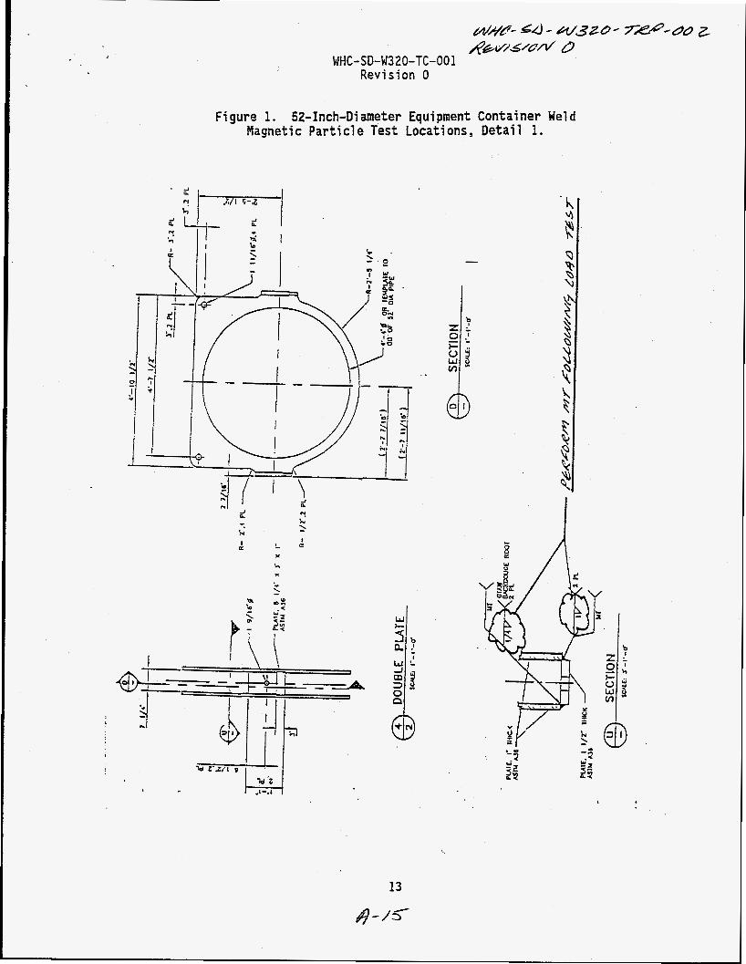
Fi gure 1. 52-Inch-Di meter Equipment Container We1 d Magnetic Parti cl e Test Locations , Detai 1 1.
T k I e
P 0
r'; I w k-
13
4 4 5

WHC-SD-W320-TC-001 Revision 0
Fi gure 2. 52-Inch-Di ameter Equipment Container We1 d Magnetic Particle Test Locations, Detail 2.
14
4 -/b

MAGNETIC PARTICLE EXAMINATION REPORT


K;AISER ENGINEERS HANFclRD
I AREA I ACC. [ REJ. I INDICATIONS
Level KEH Approval Level
Date Jt-
Dat
Distributiod: Pin( - Originator I KEH 0926.00 (02193)
A- i 4

MAGNETIC PA TlON REPORT \
K;LI/S€R EffGlNEERS 1 HANFCIRCI I
Particles Used:
Dn/ Wet
Ampere Turn>/,/ I Prod Spacing I e I’
Examination Standard 1,Acceptance Standard ,
Amps
5nD AREA ACC. REJ. INDICATIONS & & ? =
=-r w ~ J O * / - ~ *03 /
A J 3 J
J
I KXfSER ENGiNEERS HANFURLI
MAGNETIC PARTICLE EXAMINATION REPORT ,
I Particles Used: I WeldPart No. I Welder
6-7667 Yoke ,/ AC / DC
,’
Level
.I 2 KEH Approval
Datd v Date
f KEH 0926.00 102/931 8/3&
A+ z /