![Active GPRS IO Users Manual v2[1]](https://static.fdocuments.us/doc/165x107/577ce6411a28abf103927bc4/active-gprs-io-users-manual-v21.jpg)
X-IO Technologies ISE using Active-Active...
43
XIO Storage October 2011 VMware vSphere Stretched Cluster with X-IO Technologies ISE using Active-Active Mirroring May 2014
Transcript of X-IO Technologies ISE using Active-Active...

XIO Storage
October 2011
VMware vSphere Stretched Cluster with
X-IO Technologies ISE using
Active-Active Mirroring May 2014
Table of Contents
Table of Contents .......................................................................................................... 2
Table of Figures............................................................................................................. 3
Introduction ................................................................................................................... 4
Executive Summary .................................................................................................................................. 4
Stretch Cluster Solutions Benefits ............................................................................................................ 6
Solution Overview ......................................................................................................... 8
ISE AAM Overview .................................................................................................................................... 8
Solution Components .............................................................................................................................. 13
Configuration and Best Practices ............................................................................................................ 14
Failure Scenarios ........................................................................................................ 20
Single Host Failure in Site-1 Datacenter ................................................................................................. 21
Single Host Isolation in Site-1 Datacenter .............................................................................................. 22
Storage Partition Communication Failure ............................................................................................... 23
Datacenter Partition Communication Failure .......................................................................................... 24
Disk Shelf (ISE DataPac) Failure in Site-1 Datacenter ........................................................................... 25
Full Storage Failure in Site-1 Datacenter ................................................................................................ 26
Permanent Device Loss .......................................................................................................................... 27
Full Compute Failure in Site-1 Datacenter .............................................................................................. 28
Loss of Complete Site-1 Datacenter ....................................................................................................... 29
Loss of Witness ....................................................................................................................................... 31
Loss of Witness and Complete Site-1 Datacenter .................................................................................. 32
Datacenter Partition and Witness Communication Failure ..................................................................... 33
Test Case Table ...................................................................................................................................... 34
Conclusion ................................................................................................................... 37
Appendix ...................................................................................................................... 38
Troubleshooting ...................................................................................................................................... 38
Sample Zoning ........................................................................................................................................ 38
Contact X-IO technologies ...................................................................................................................... 43
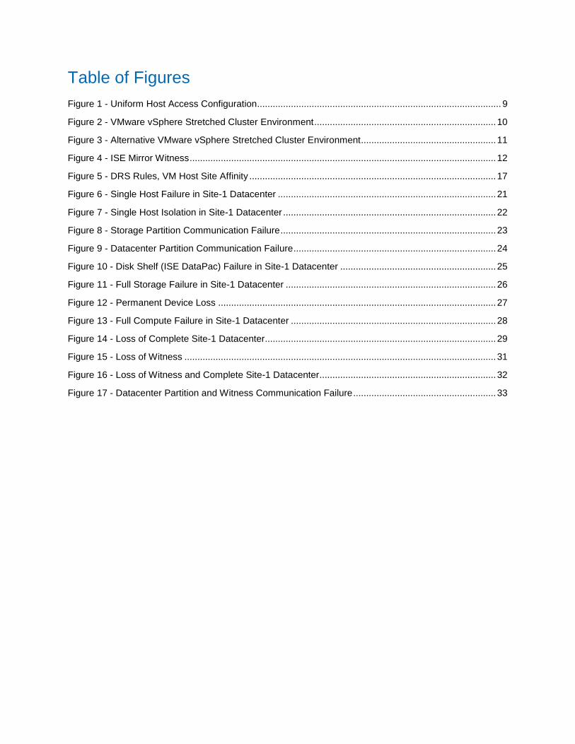
Table of Figures
Figure 1 - Uniform Host Access Configuration .............................................................................................. 9
Figure 2 - VMware vSphere Stretched Cluster Environment ...................................................................... 10
Figure 3 - Alternative VMware vSphere Stretched Cluster Environment .................................................... 11
Figure 4 - ISE Mirror Witness ...................................................................................................................... 12
Figure 5 - DRS Rules, VM Host Site Affinity ............................................................................................... 17
Figure 6 - Single Host Failure in Site-1 Datacenter .................................................................................... 21
Figure 7 - Single Host Isolation in Site-1 Datacenter .................................................................................. 22
Figure 8 - Storage Partition Communication Failure ................................................................................... 23
Figure 9 - Datacenter Partition Communication Failure .............................................................................. 24
Figure 10 - Disk Shelf (ISE DataPac) Failure in Site-1 Datacenter ............................................................ 25
Figure 11 - Full Storage Failure in Site-1 Datacenter ................................................................................. 26
Figure 12 - Permanent Device Loss ........................................................................................................... 27
Figure 13 - Full Compute Failure in Site-1 Datacenter ............................................................................... 28
Figure 14 - Loss of Complete Site-1 Datacenter......................................................................................... 29
Figure 15 - Loss of Witness ........................................................................................................................ 31
Figure 16 - Loss of Witness and Complete Site-1 Datacenter .................................................................... 32
Figure 17 - Datacenter Partition and Witness Communication Failure ....................................................... 33

4 | VMware vSphere Stretched Cluster with X-IO Active-Active Mirroring
Introduction
A VMware vSphere stretched cluster on X-IO Technologies ISE storage with Active-Active Mirroring
provides a solution for maximizing availability and uptime by clustering datacenters at metro distances
apart. This solution provides the absolute highest levels of continuous availability over distance for
today’s enterprise storage and cloud environments. This solution is implemented in environments where
disaster/downtime avoidance is a requirement.
A VMware vSphere stretched cluster configuration is a VMware vSphere solution combined with storage-
based synchronous replication. These solutions are deployed in environments where the distance
between datacenters is generally limited to metropolitan or campus environments. The solutions
described in this white paper consist of X-IO ISE storage systems presenting replicated storage as a
single LUN from different geographically distributed sites. This capability is what X-IO calls Active-Active
Mirroring (AAM). The ISE provides synchronous replication and storage failover between the
geographically distributed sites. These functions work together with VMware vSphere vMotion, vSphere
High Availability, vSphere Fault Tolerance, and vSphere Dynamic Resource Scheduler for a VMware
vSphere storage stretched cluster solution.
Executive Summary
This paper discusses using VMware with X-IO ISE storage to deliver continuous availability solutions. The scope of this paper includes design considerations, constraints, operational best practices, and failure
scenarios. This paper details testing performed by X-IO Technologies. All recommendations and best practices defined in this reference architecture must be implemented to achieve the high availability design of the system.
Audience
This paper is intended for individuals with a technical background who will be designing, deploying, or
managing a VMware stretched cluster with X-IO ISE storage.

5 | VMware vSphere Stretched Cluster with X-IO Active-Active Mirroring
Assumptions
Familiarize yourself with virtualized infrastructures and with networking in a heterogeneous environment.
A basic knowledge of VMware ESX, ESXi and vCenter Server, servers, ISE, ISE Mirroring, and
management software such as ISE Mirror Manager, Virtual View, and vSphere Plugin is required.
This white paper describes testing performed in October 2013 at X-IO headquarters in Colorado Springs,
Colorado, USA.
Reference Material
vSphere Metro Storage Cluster Case Study http://www.vmware.com/files/pdf/techpaper/vSPHR-CS-MTRO-STOR-CLSTR-USLET-102-HI-RES.pdf VMware vSphere 5.1/5.5 Availability VMware vSphere 5.1/5.5 Resource Management Guide VMware vSphere 5.1/5.5 Storage Guide http://www.vmware.com/support/pubs/vsphere-esxi-vcenter-server-pubs.html
X-IO ISE Mirroring Release Notes and X-IO ISE Mirroring User Guide https://xone.xiotech.com/support/supportmatrix/Matrix/ISE%20Mirroring_System_Page.aspx
X-IO ISE Best Practices Guide and Configuration Guide https://xone.xiotech.com/resources/servicedownloads/Best_Practices/Best%20Practices%20Guide_Rev_D.pdf
X-IO ISE Support Matrix (including VMware support status)
https://xone.xiotech.com/support/supportmatrix/Pages/default.aspx
Technical Requirements and Constraints
The following are technical requirements and constraints for a VMware vSphere stretched cluster with
X-IO Technologies ISE using Active-Active Mirroring.
VMware requirements
Note: Refer to the VMware vSphere Metro Storage Cluster Case Study for current requirements.
The maximum supported network latency between sites for the VMware ESXi management
networks is 10 ms round-trip time (RTT).
o 10 ms of latency for vMotion is supported only with VMware vSphere Enterprise Plus
Edition licenses (vSphere vMotion Metro).
A minimum of 622 Mbps network bandwidth, configured with redundant links, is required for the
ESXi vMotion network.
vSphere vCenter Server must be connected to ESXi hosts in both datacenters.
A ‘stretched layer 2 network’ to ensure seamless network capability regardless of which location
the VM runs in.

6 | VMware vSphere Stretched Cluster with X-IO Active-Active Mirroring
Any IP subnet used by the virtual machine must be accessible by all ESXi hosts in all datacenters
within the stretched cluster.
X-IO storage requirements
Storage connectivity using Fibre Channel (FC). FC switched SAN for host-storage connectivity
and storage inter-link connectivity. FCIP inter-site links are not yet supported.
The maximum latency for synchronous storage replication links is 5 ms RTT. VMware also states
the same requirement.
ISE Mirrors created in Active-Active mode.
X-IO ISE Mirror Witness is mandatory for this solution. The Witness must be deployed in a
separate failure domain. The Witness must not be dependent upon the ISE storage.
Ethernet connectivity between both ISEs and Mirror Witness for ISE communication outside the
data path.
For additional X-IO storage requirements and constraints, refer to the X-IO ISE Mirroring Release Notes.
VMware and X-IO storage best practices for configuration are discussed in this document.
Stretch Cluster Solutions Benefits
A stretched cluster is one in which some of the servers within the cluster reside in physically separate locations. The site locations might be in different facilities within a metropolitan area, different buildings, or different floors of a datacenter. VMware stretched cluster infrastructures are implemented with the goal of the same benefits that high availability clusters provide to a local site but with two geographically separated datacenters. The host cluster should behave identically as it would in a single datacenter, regardless of the distance between the nodes. A key stretched cluster benefit is the capability to migrate virtual machines between sites with VMware vSphere vMotion and vSphere Storage vMotion, enabling on-demand and nonintrusive mobility of workloads.
Stretched cluster solutions offer the following benefits:
Workload mobility
Cross-site automated load balancing
Enhanced downtime avoidance
Disaster avoidance
X-IO ISE Mirroring provides the ideal foundation for VMware High Availability and Fault Tolerance
clustering over distance with no added complexity. The following table highlights differences between the
solution use cases of VMware High Availability (HA) and Fault Tolerance (FT), allowing the business to
choose the correct solution. The administrator enables HA and FT in the VMware vSphere setup. FT is an
optional higher level of availability if desired. Recovery Point Objective (RPO) is the maximum tolerable
period during which data is unavailable due to a major incident. Recovery Time Objective (RTO) is the
duration of time in which data availability is restored after a disruption.
7 | VMware vSphere Stretched Cluster with X-IO Active-Active Mirroring
Automatic Distance VM Restart
Based or
Continuous RPO Storage
RTO System
RTO VM Restart
Granularity Stretched L2
Network
Required
VMware
FT Automatic <1 ms Continuous 0 0 0 N/A Yes
VMware
HA Automatic <5 ms VM Restart 0 0 Seconds
to minutes High/Med/
Low Yes
Use Case for VMware HA
A VMware HA solution is an ideal fit for a customer with high availability requirements and two
datacenters that are no more than 5 ms RTT apart. A VMware HA solution includes downtime and
disaster avoidance as well as fully automatic service restarts in the event of a total site outage.
Use Case for VMware FT
A VMware FT solution is an ideal fit for a customer with fault tolerance requirements and two datacenters
that are no more than 1 ms RTT apart, typically campus-type distances. A VMware FT solution provides
continuous availability, where effectively one datacenter is in lock step with the other. This type of
configuration can be thought of as two datacenters configured using RAID-1 redundancy.
Data Availability
The ISE Active-Active mirroring distributes the same block volume to more than one location and ensures that cluster environments with VMware HA and FT can simply leverage this capability and be easily and transparently deployed over distance.
Data Integrity
Synchronous (real time) replication provides a high level of data consistency protection. It ensures that the remote data is identical to the local data. In synchronous replication, an I/O operation from a virtual machine is not complete until confirming the completion at the primary and recovery site. The ISE Active-Active Mirroring’s advanced data caching and distributed cache coherency provide workload resiliency, automatic sharing, balancing and failover of storage domains, and local and remote data access with predictable service levels.
8 | VMware vSphere Stretched Cluster with X-IO Active-Active Mirroring
Solution Overview
A VMware HA/DRS cluster is created across two sites using ESXi 5.1/5.5 hosts and is managed by
vCenter Server 5.1/5.5. The vSphere Management, vMotion, and virtual machine networks are connected
using a network between the two sites. This solution supports a single stretched vSphere cluster.
This architecture uses X-IO storage hardware and software for two datacenters in a VMware stretched
cluster environment. The X-IO solution provides a simple solution with fewer hardware and software
components compared to traditional metro storage cluster solutions. The following are the X-IO
components for this environment:
X-IO ISE with ISE AAM firmware capability - An enterprise-class storage platform.
X-IO ISE Mirror Witness - Software agent executing in a separate failure domain that is used as an arbitrator for AAM solutions.
ISE Mirror Manager - ISE mirror management interface.
ISE AAM Overview
An ISE Mirror in a stretched configuration is considered a single storage subsystem that spans two sites.
In the X-IO stretched cluster configuration, the datastore is read-write accessible from both sites. Each
ISE within a mirror configuration will have active read and write access to a given datastore. This solution
requires ISE Mirrors to be created in Active-Active mode.
In this solution, a primary datastore is synchronously replicated to a read-write secondary datastore. ESXi
hosts from different sites can access the storage on both sites and see both mirrored volumes as a single
LUN and a single datastore. There are host data paths to both mirrored volumes. The setup is simple for
an IT administrator because the volume presentations to the hosts at both sites look the same, given the
active-active architecture.
The addition of active data paths in Active-Active ISE Mirroring provides a transparent recovery from host
accessibility failures. The host read-write access to the distributed volume at both sites allows for
seamless path changes. No custom path management software is required in the host layer to spoof the
identity and control the replication failover when required to trigger the path changes. The volume path
switch-over occurs automatically with native host multipathing.
The host read-write access to the distributed volume on both sites allows for potential performance
benefit by load balancing across two ISEs. An X-IO stretched cluster allows for I/O to be serviced by
100% of the available storage at both physical locations. All I/O can be sent to or received from any
storage controller. Active-Active Mirroring helps offset the latency overhead of replicating over distance
and under some workloads has been proven to improve the performance up to 15% compared to a non-
replicated volume. Active-Active Mirroring can increase performance due to the fact that reads can be
satisfied locally by both mirror copies on either ISE, fully maximizing the disk spindles from both ISEs.
The second storage ISE contributes to the overall system performance.
The X-IO stretched cluster solution supports the category of uniform host access. A uniform host access
configuration is when ESXi hosts from both sites are all connected to ISE storage in the storage cluster
across all sites. Paths presented to ESXi hosts are stretched across distance. The X-IO solution does not
support the non-uniform host access configuration.

9 | VMware vSphere Stretched Cluster with X-IO Active-Active Mirroring
The following diagram logically shows a uniform host access configuration to a distributed virtual machine
file system (VMFS) datastore with read-write access from both datacenters.
Figure 1 - Uniform Host Access Configuration

10 | VMware vSphere Stretched Cluster with X-IO Active-Active Mirroring
The following diagram provides an overview of the VMware vSphere stretched cluster environment that
was tested by X-IO.
Figure 2 - VMware vSphere Stretched Cluster Environment

11 | VMware vSphere Stretched Cluster with X-IO Active-Active Mirroring
The following diagram shows an optional variant configuration that may be deployed in campus
environments where the distance is limited; for example, between buildings, between labs in the same
building, or between racks in the same lab.
Figure 3 - Alternative VMware vSphere Stretched Cluster Environment

12 | VMware vSphere Stretched Cluster with X-IO Active-Active Mirroring
ISE Mirror Witness
The X-IO ISE Mirror Witness is an important component in an X-IO stretched cluster configuration. Both ISEs uses Mirror Witness as a third-party arbitrator when inter-ISE communication is lost so they both do not continue serving I/O “split brain” for the same distributed volume. Continuing to service I/O “split brain” could corrupt the data. The ISE Mirror Witness provides a third-party view of whether it is safe to continue servicing I/O or if one side of the mirror should be disabled from host access. The ISE Mirror Witness is a software agent that runs on a Windows server or virtual machine. Mirror
Witness is recommended to be deployed in a separate failure domain with connectivity to both stretch
cluster sites. The separate failure domain may not necessarily be located in a third site but may be a
different building or different lab within the same building or a different rack in the same lab. The location
is customer specified. The goal is to locate the Witness such that the secondary storage does not lose
access to the Witness if it loses access to the primary storage.
Figure 4 - ISE Mirror Witness

13 | VMware vSphere Stretched Cluster with X-IO Active-Active Mirroring
Solution Components
These components create a VMware vSphere stretched cluster environment.
Note: Refer to the X-IO ISE Support Matrix for current list of support and certification, including VMware
support status.
Hardware Requirements
ESXi 5.1/5.5 hosts. Check VMware HCL for certified server hardware.
Two ISE 200 or ISE 700 per mirror pair
Windows Server 2008 SP2/R2 SP1 or Windows Server 2012/2012 R2 server or VM to run: o ISE Mirror Witness o ISE Mirror Manager
FC switches and HBAs in accordance with the X-IO ISE Support Matrix
FC inter-site link cables with maximum distance of 40 Km. FCIP inter-site links are not yet supported.
Note: ESXi hosts may be either locally booted or boot from SAN (BFS).
Software Requirements
vSphere 5.1/5.5
vSphere products: PowerCLI, vSphere client, vCenter Server, X-IO vCenter plug-in, Orchestrator
ISE firmware 2.6.0 or later
ISE Mirror Witness 1.0.0.0
ISE Mirror Manager 1.0.6.0 or later
ISE Manager with Virtual View or use web browser ISE management interface
Licensing Requirements
vSphere 5 Enterprise Plus License that includes the vSphere vMotion Metro feature
ISE Mirror License

14 | VMware vSphere Stretched Cluster with X-IO Active-Active Mirroring
Configuration and Best Practices
For solution installations, contact the X-IO Account team to submit the X-IO ISE Mirroring Solution
Assurance Worksheet.
Note: VMware best practices noted in this section are from the VMware vSphere Metro Storage Cluster Case Study. Refer to the VMware documentation for current recommendations and more detailed guidance.
vSphere HA and DRS Best Practices
vSphere HA will monitor for failed hosts within a vSphere HA cluster and restart virtual machines on other
hosts within the cluster. VMware DRS is used to distribute load within a cluster. VMware Storage DRS
enables aggregation of datastores into a single unit of consumption from an administrative perspective,
and it balances virtual machine disks when defining thresholds are exceeded. It ensures sufficient disk
resources are available to your workload.
Note: This solution supports a single stretched vSphere cluster.
In this section, we describe the proper setup of vSphere HA, VMware DRS, and VMware Storage DRS,
which is critical to ensure that the environment is properly balanced without impacting availability or
severely increasing operational expenditure. Periodically validating the settings is important. Ignoring the
requirements makes the environment confusing to administer and less predictable during the various
failure scenarios. The following summarizes VMware recommendations for vSphere, DRS and Storage
DRS setup in a stretched cluster environment.
vSphere HA
1. vSphere HA must be enabled.
2. VMware recommends setting the Admission Control policy type to “Percentage of cluster resources reserved as failover spare capacity.” CPU and Memory should be configured to 50% to provide sufficient host resource capacity for a full site failure.
3. VMware recommends specifying a minimum of two additional isolation IP addresses and that
each of these addresses is site local.
vSphere HA advanced setting to be used is das.isolationaddress.
Note: The following knowledge base link has more information on this setting. http://kb.vmware.com/selfservice/microsites/search.do?language=en_US&cmd=displayKC&externalId=1002117
4. VMware recommends increasing the number of heartbeat datastores from two to four.
Four is recommended in a stretched-cluster environment to provide full redundancy in
both locations. Selecting four specific datastores—two from one site and two from the
other—as preferred heartbeat datastores is also recommended.
5. VMware recommends Leave Powered On as the isolation response setting for VMs.
6. VMware recommends choosing “Select any of the cluster data stores taking into account my
preferences.” Select two datastores from each site.
7. VMware recommends placing all the files for a given virtual machines on a single datastore, ensuring
that PDL conditions can be mitigated by vSphere HA.

15 | VMware vSphere Stretched Cluster with X-IO Active-Active Mirroring
8. VMware recommends setting disk.terminateVMOnPDLDefault set to True. This is the default setting.
9. VMware recommends setting das.maskCleanShutdownEnabled to True. This is not the default
setting. A clean shutdown will prevent the virtual machine from restarting.
Note: The following blog has more information about topics (8) and (9) above:
http://blogs.vmware.com/vsphere/2012/06/diskterminatevmonpdldefault-enabled-and-
dasmaskcleanshutdownenabled-disabled.html
10. VMware recommends disabling Disk.AutoRemoveOnPDL (new to vSphere 5.5) for devices to avoid
host rescan when the affected LUN comes back online. The default setting for
Disk.AutoRemoveOnPDL is Enabled, to disable it set Disk.AutoRemoveOnPDL to 0.
vSphere DRS
1. vSphere DRS must be enabled.
2. VMware recommends setting the DRS Automation Level to Manual.
3. VMware recommends implementing DRS affinity rules to enable logical separation of virtual
machines by site.
4. X-IO recommends that VMs be placed on hosts where their master mirror member is preferred.
Note: One of the two members in the ISE mirror is the designated master for cache
coherency locking for Active-Active Mirroring. The mirror master member is an attribute of the
mirror that is visible through ISE Mirror Manager. ISE mirrors may be configured bi-directional
(some mastered at one site and the others mastered at the other site).
5. VMware recommends aligning virtual machine-host affinity with storage configuration.
Run the virtual machines on hosts at the same site as the array configured as the primary
(or master for ISE).
6. VMware recommends implementing “Should rules” (Should Run On Hosts In Group) when
Witness is enabled so that they can be violated by vSphere HA in the case of a site failure.
“Must rules” could lead to prolonged service outages due to the inability for HA to restart
the VMs in the other physical datacenter.
Note: X-IO recommends deploying ISE Mirror Witness in stretched cluster configurations. If
Mirror Witness is not enabled, X-IO recommends implementing “Must rules” instead of
“Should rules.” “Must rules” could also help protect from potential data corruption in true split
brain conditions; however this would limit data mobility between sites.
7. VMware recommends manually defining sites by creating a group of hosts that belong to a site
and adding virtual machines to these sites based on the affinity of the datastore on which they are
provisioned.
vSphere Storage DRS
1. VMware recommends enabling Storage DRS.
16 | VMware vSphere Stretched Cluster with X-IO Active-Active Mirroring
2. VMware recommends configuring Storage DRS in manual mode.
3. VMware recommends creating datastore clusters based on the storage configuration with respect
to storage site affinity.
Datastores with affinity for site A should not be mixed in datastore clusters with
datastores with affinity for site B.
4. VMware recommends aligning naming conventions for datastore clusters with virtual machine-host affinity rules.
For an explanation of the vSphere settings and screenshots, refer to the VMware vSphere Metro Storage Cluster Case Study. For an in-depth explanation of vSphere, VMware DRS, and VMware Storage DRS, refer to the VMware vSphere 5.1/5.5 Availability Guide and the vSphere 5.1/5.5 Resource Management Guide. Proper setting of VM host affinity rules is an important aspect of the setup. With the use of ISE Mirror
Witness (recommended), the rule “Should Run on Hosts in Group” should be used primarily for availability
and mobility. A site failure under “should rules” would ensure that the VMs that failed would be restarted
at the remaining site. The workload from the failed site would be able to resume at the remaining site.
When using Mirror Witness, “Must Run on Hosts in Group” is not recommended due to potential
availability issues in specific scenarios. A site failure under the “must rules” would prevent workload from
being accessible from the remaining site.
Set up the same host affinity rules for related services, such as the application and its related database.
The following screenshot shows an example of VM host site affinity. Site A’s VMs should run on hosts in
Site A’s host group. Site B’s VMs should run on hosts in Site B’s host group. If Site B fails, DRS will allow
the VMs from Site B to restart on hosts in Site A. If “must” rules are used, VMs from the failed site will not
be allowed to restart on hosts in the site that is still available, causing an extended outage for those VMs.

17 | VMware vSphere Stretched Cluster with X-IO Active-Active Mirroring
Figure 5 - DRS Rules, VM Host Site Affinity

18 | VMware vSphere Stretched Cluster with X-IO Active-Active Mirroring
SAN Best Practices
The following summarizes X-IO’s recommendations for SAN setup for ISE Mirroring.
Local Clusters (FC distances)
1. X-IO recommends dual fabrics for redundancy.
2. See the X-IO ISE Best Practices Guide and Configuration Guide for cross-connected fabric
diagrams.
3. X-IO recommends redundant paths from each MRC (i.e., at least one port from each MRC will
connect to each of two fabrics) to ensure that a fabric outage will not result in a downtime event.
Stretched Clusters
1. X-IO recommends dual FC inter-site links (ISLs) for redundancy when feasible.
Note: A single FC ISL is acceptable for a lower-cost solution when dual FC ISLs are not feasible.
A single ISL increases the risk of a loss of FC connectivity. A single FC ISL still results in the
same behavior for all the test scenarios outlined in this paper.
2. X-IO supports a uniform host access configuration. Non-uniform is not supported.
Zoning
1. X-IO recommends either Single Initiator Zoning or 1-to-1 zoning. Open zoning is not
recommended.
2. Single Initiator Zoning
a. Single Initiator Zoning allows for a host World Wide Port Name (WWPN) to be grouped
with each MRC that it needs to see.
b. There will be no need for an extra Mirror Zone that contains all MRC WWPNs that need
to see each other for ISE Mirroring since the MRC WWPNs will already be a part of each
zone.
3. 1-to-1 Zoning + Mirror Zone
a. 1-to1 Zoning will include a host WWPN member and an MRC WWPN member.
b. Many zones will be needed to pair a host WWPN member with each MRC WWPN
member that it needs to see.
c. An extra zone that contains the MRC WWPNs from both ISEs participating in an ISE
Mirror configuration also needs to be created.
The X-IO solution uses native VMware multipathing. No extra software is required to run in the host. The
Path Selection Policy (PSP) used with Active/Active ISE Mirrors is recommended to be Round Robin.
Round Robin provides read/write access from all available paths. The benefit with the X-IO solution is that
it maximizes bandwidth from all available paths for improved performance. If Fixed Path multipathing is
used instead of Round Robin, it is recommended to choose a fixed path that is on the mirror master ISE.
The mirror master is an attribute of the mirror visible through ISE Mirror Manager.

19 | VMware vSphere Stretched Cluster with X-IO Active-Active Mirroring
ISE Best Practices
The following summarizes X-IO’s recommendations that apply to the storage setup.
ISE
1. Maximum of one datastore per mirrored LUN.
2. Maximum of 16 Active-Active mirrored LUNs per ISE pair.
3. Maximum of eight ISE pairs sharing the same ISE Mirror Witness.
4. Maximum of eight ISE pairs sharing the inter-site storage replication links.
5. Place VMs in relation to where they are mastered (site affinity).
6. Run ISE Mirror Manager and ISE Mirror Witness in the same Windows Server VM.
Refer to the X-IO ISE Best Practices Guide and Configuration Guide, X-IO ISE Mirroring Release Notes,
and X-IO ISE Mirroring User Guide for a full list of ISE best practices and constraints.
A key recommendation that applies to ISE in a stretched cluster is placing VMs in relation to where they
are mastered (site affinity). The mirror master is visible in ISE Mirror Manager. The mirror master is a
source volume that was specified during mirror creation. The mirror mastership may change based on
failure conditions outlined in the “Failure Scenarios” section of this document. The mastership will return
to the original location once the mirrors can be resynchronized.
ISE Mirroring can be used with either the ISE 200 series or ISE 700 series hybrid storage arrays. Using
ISE 700 series at both sites provides exceptional balanced performance at both sites, with CADP
upgrades from HDD to SDD occurring on both ISEs. The initial synchronization has algorithms to quickly
balance the performance on both ISEs. With the host performing Round Robin multipath I/Os and reads
occurring locally, a balanced CADP per site is achieved.
vStorage API for Array Integration (VAAI) is an application program interface framework from VMware
that enables certain storage tasks to be offloaded from the VMware server virtualization hardware to the
storage. ISE Mirrors support the Atomic Test and Set (ATS) command but not yet the full VAAI command
set (as of ISE 2.6.0 firmware).
If storage capacity for a given datastore runs out, the size of the underlying ISE volume may be
expanded. To expand the volume, the ISE mirror must be first broken and then re-created after the
volume expansion.

20 | VMware vSphere Stretched Cluster with X-IO Active-Active Mirroring
Failure Scenarios
The following failure scenarios were discussed in the vSphere Metro Storage Cluster Case Study. We will
review them with any added notations as they apply to the X-IO stretched cluster solution.
Single host failure in Site-1 datacenter
Single host isolation in Site-1 datacenter
Storage partition communication failure
Datacenter partition communication failure
Disk shelf (ISE DataPac) failure in Site-1 datacenter
Full storage failure in Site-1 datacenter
Permanent device loss
Full compute failure in Site-1 datacenter
Loss of complete Site-1 datacenter
Loss of Witness
Loss of Witness and complete Site-1 datacenter
Datacenter partition and Witness communication failure
All of these failure scenarios were extensively tested by X-IO. The following were our findings per
scenario.

21 | VMware vSphere Stretched Cluster with X-IO Active-Active Mirroring
Single Host Failure in Site-1 Datacenter
In this scenario, a complete host failure was tested in the Site-1 datacenter.
Figure 6 - Single Host Failure in Site-1 Datacenter
Result Virtual machines were restarted by vSphere HA in accordance with host affinity rules. Explanation The virtual machines can potentially be restarted on a host in the other datacenter given the “should rules.” VMware DRS will attempt to correct any violated affinity rules and migrate virtual machines in
accordance with their rules. Misplacement may not necessarily lead to increased latency with X-IO’s AAM given the efficiency of read/write access at both sites.

22 | VMware vSphere Stretched Cluster with X-IO Active-Active Mirroring
Single Host Isolation in Site-1 Datacenter
In this scenario, single host isolation was tested in the Site-1 datacenter.
Figure 7 - Single Host Isolation in Site-1 Datacenter
Result Because the isolation response was set to the recommended Leave Powered On, virtual machines continued running. Explanation
The event had no effect on the underlying X-IO storage.

23 | VMware vSphere Stretched Cluster with X-IO Active-Active Mirroring
Storage Partition Communication Failure
In this scenario, a failure was tested on the storage network between datacenters.
Figure 8 - Storage Partition Communication Failure
Result Virtual machines remained running with no impact. Explanation Each LUN has storage site affinity defined and VMware DRS rules aligned with this affinity. None of the virtual machines were impacted because their storage remained available within the site. Both ISEs recognized the storage partition and disabled access to paths to the mirror volume that was not acting as the master. The ISE disabled access by returning SCSI sense code 05/25/00. The hosts continued read/write access to the master-side paths of the mirror. When the storage partition was restored, the ISE recognized it and restored access to both sites and automatically resynchronized the data. Host read/write access continued on all available paths while a resynchronization was in progress. The ISEs transparently routed data to the mirror copy with the current data. The resynchronization copied only block ranges that changed while the storage partition existed. For an extended communication failure, the resynchronization copied all written blocks since the volume was created.
24 | VMware vSphere Stretched Cluster with X-IO Active-Active Mirroring
Datacenter Partition Communication Failure
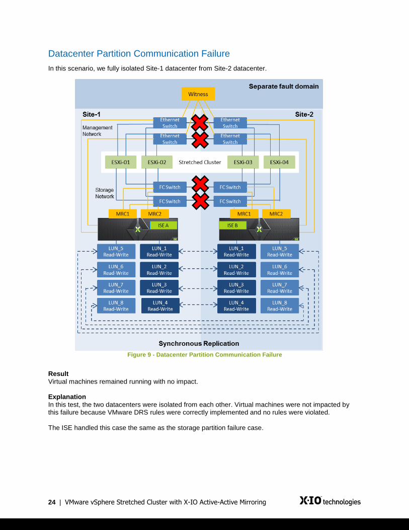
In this scenario, we fully isolated Site-1 datacenter from Site-2 datacenter.
Figure 9 - Datacenter Partition Communication Failure
Result Virtual machines remained running with no impact. Explanation In this test, the two datacenters were isolated from each other. Virtual machines were not impacted by this failure because VMware DRS rules were correctly implemented and no rules were violated. The ISE handled this case the same as the storage partition failure case.
25 | VMware vSphere Stretched Cluster with X-IO Active-Active Mirroring
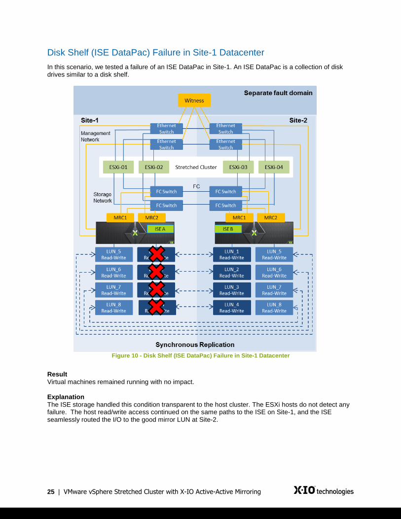
Disk Shelf (ISE DataPac) Failure in Site-1 Datacenter
In this scenario, we tested a failure of an ISE DataPac in Site-1. An ISE DataPac is a collection of disk drives similar to a disk shelf.
Figure 10 - Disk Shelf (ISE DataPac) Failure in Site-1 Datacenter
Result Virtual machines remained running with no impact. Explanation The ISE storage handled this condition transparent to the host cluster. The ESXi hosts do not detect any failure. The host read/write access continued on the same paths to the ISE on Site-1, and the ISE seamlessly routed the I/O to the good mirror LUN at Site-2.

26 | VMware vSphere Stretched Cluster with X-IO Active-Active Mirroring
Full Storage Failure in Site-1 Datacenter
In this scenario, we tested a full storage system failure in Site-1 datacenter.
Figure 11 - Full Storage Failure in Site-1 Datacenter
Result Virtual machines remained running with no impact. Explanation When the full storage system failed in Site-1 datacenter, the failover was seamless as the hosts already had read/write access to the Site-2 storage. From a virtual machine’s perspective it was transparent. No action was required from vSphere or the IT administrator. All I/O passed across the intra-site connection to the other datacenter because virtual machines remained running in Site-1 datacenter while their datastores were accessible only in Site-2 datacenter. vSphere HA did not detect this type of failure. ISE B detected ISE A was down, with loss of both storage FC network communication and management Ethernet network communication. The Mirror Witness also lost communication with ISE A. I/O seamlessly continued through the surviving ISE B as paths were already active.

27 | VMware vSphere Stretched Cluster with X-IO Active-Active Mirroring
Permanent Device Loss
In this scenario, we tested setting a LUN at Site-1 to an offline non-operative state and also tested removing the host presentation of a LUN at Site-1.
Figure 12 - Permanent Device Loss
Result Virtual machines remained running with no impact. Explanation In the scenario of setting a LUN to an offline non-operative state, the ISE handled this failure the same as a DataPac failure. The ESXi hosts do not detect any failure. The host read/write access continued on the same paths to ISE A at Site-1. The ISE seamlessly routed I/O to the good mirror LUN on ISE B at Site-2. In the scenario of removing the host presentation to a LUN at Site-1, the host read/write access continued on available paths to the mirrored LUN at Site-2. The ISE returned SCSI sense code 05/25/00 on the paths to the unpresented LUN, but native multipathing redirects all I/O to remaining available paths and the error was not detected by vSphere HA. Therefore, the virtual machines were not killed by the ESXi hosts.
28 | VMware vSphere Stretched Cluster with X-IO Active-Active Mirroring
Full Compute Failure in Site-1 Datacenter
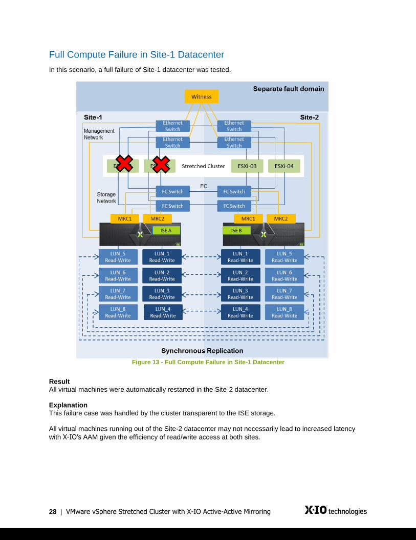
In this scenario, a full failure of Site-1 datacenter was tested.
Figure 13 - Full Compute Failure in Site-1 Datacenter
Result All virtual machines were automatically restarted in the Site-2 datacenter. Explanation This failure case was handled by the cluster transparent to the ISE storage. All virtual machines running out of the Site-2 datacenter may not necessarily lead to increased latency
with X-IO’s AAM given the efficiency of read/write access at both sites.

29 | VMware vSphere Stretched Cluster with X-IO Active-Active Mirroring
Loss of Complete Site-1 Datacenter
In this scenario, a full failure of Site-1 datacenter was tested.
Figure 14 - Loss of Complete Site-1 Datacenter
Result All virtual machines were automatically restarted in the Site-2 datacenter. Explanation In this scenario, the hosts in Site-2 datacenter lost contact with the vSphere HA master node and elected a new vSphere HA master node. The failover was seamless as the hosts already had read/write access to the Site-2 ISE storage. After the failover, the new vSphere HA master node accessed the per-datastore files that vSphere HA uses to record the set of protected virtual machines. The vSphere HA master node attempted to restart those virtual machines that were not running on the surviving hosts in Site-2 datacenter. In our scenario, all virtual machines were restarted within seconds (or up to 2 minutes for the maximum number of virtual machines) after failure and were fully accessible and functional again. The ISE handled this case the same as a detected full storage failure. ISE B detected ISE A was down, with loss of both storage FC network communication and management Ethernet network communication.

30 | VMware vSphere Stretched Cluster with X-IO Active-Active Mirroring
The Mirror Witness also lost communication with ISE A. I/O seamlessly continued through the surviving ISE B as paths were already active. All virtual machines running out of the Site-2 datacenter may not necessarily lead to increased latency
with X-IO’s AAM given the efficiency of read/write access at both sites.

31 | VMware vSphere Stretched Cluster with X-IO Active-Active Mirroring
Loss of Witness
In this scenario, a failure of the ISE Mirror Witness was tested.
Figure 15 - Loss of Witness
Result Virtual machines remained running with no impact. Explanation
In this scenario, the failed or inaccessible Witness had no effect on the underlying X-IO storage I/O. Both ISEs reported the Witness was inaccessible and an alert was sent to notify the administrator. An inaccessible Witness affects the I/O path only if the ISEs are unable to mirror I/Os.
32 | VMware vSphere Stretched Cluster with X-IO Active-Active Mirroring
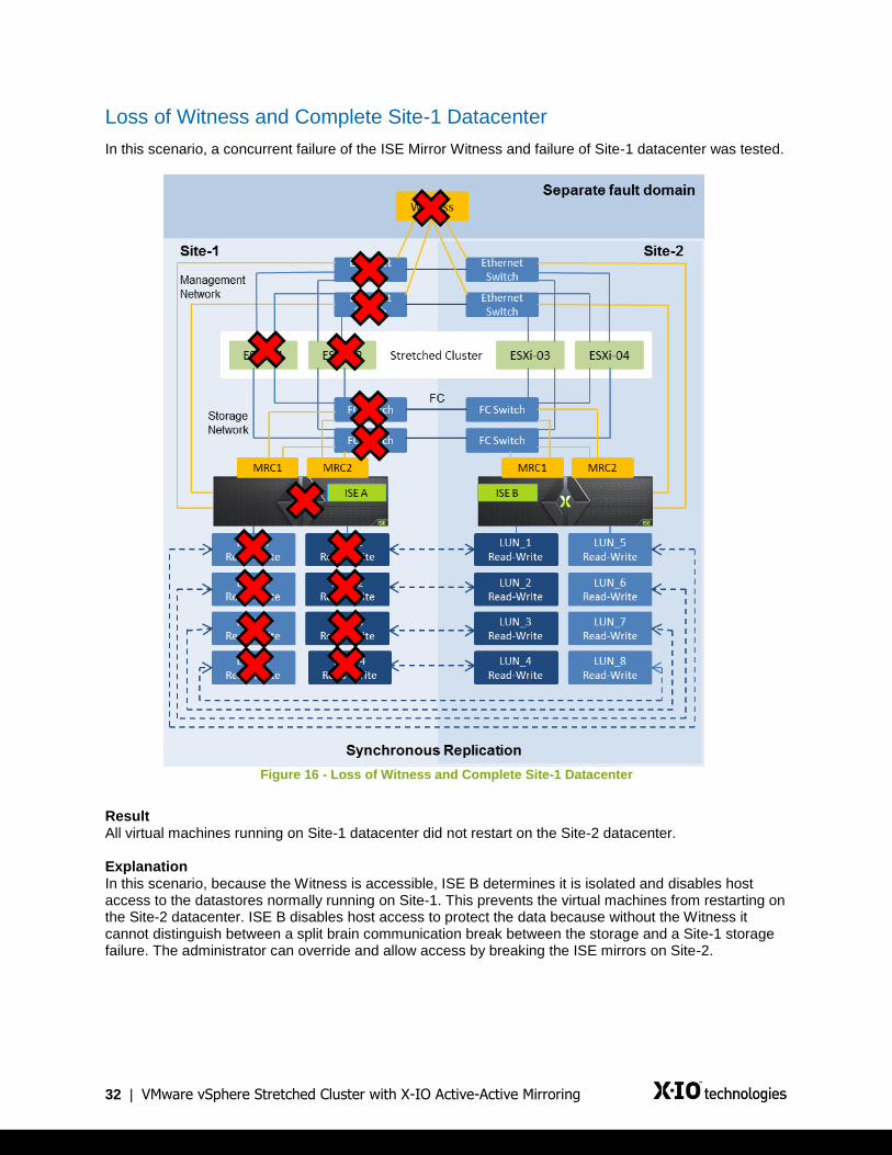
Loss of Witness and Complete Site-1 Datacenter
In this scenario, a concurrent failure of the ISE Mirror Witness and failure of Site-1 datacenter was tested.
Figure 16 - Loss of Witness and Complete Site-1 Datacenter
Result All virtual machines running on Site-1 datacenter did not restart on the Site-2 datacenter. Explanation In this scenario, because the Witness is accessible, ISE B determines it is isolated and disables host access to the datastores normally running on Site-1. This prevents the virtual machines from restarting on the Site-2 datacenter. ISE B disables host access to protect the data because without the Witness it cannot distinguish between a split brain communication break between the storage and a Site-1 storage failure. The administrator can override and allow access by breaking the ISE mirrors on Site-2.

33 | VMware vSphere Stretched Cluster with X-IO Active-Active Mirroring
Datacenter Partition and Witness Communication Failure
In this scenario, we fully isolated Site-1 datacenter from Site-2 datacenter. Concurrently we also isolated the ISE Mirror Witness from both Site-1 and Site-2 datacenters.
Figure 17 - Datacenter Partition and Witness Communication Failure
Result All virtual machines running on both Site-1 and Site-2 datacenters stopped running. This results in a complete outage. Explanation In this scenario, both ISEs determine they are isolated and prevent host access to protect the data because without the Witness it cannot distinguish between a split brain communication break between the storage and a remote storage failure. If storage ISL is restored, the mirroring automatically resumes. If the storage ISL cannot be restored within a timely manner, the administrator can override and allow access by breaking the ISE mirrors. The administrator choses which site should retain host access for each given mirror.

34 | VMware vSphere Stretched Cluster with X-IO Active-Active Mirroring
Test Case Table
The following table summarizes a full list of possible failure scenarios. All of these failure scenarios were
extensively tested by X-IO. The following are our findings per scenario.
Scenario X-IO Controller Behavior VMware HA/FT Behavior
Controller single path failure Controller path failover occurs. All LUNs and volumes remain connected. For FC datastores, path failover is triggered from the host and the remaining available paths from any controller will be active.
No impact
ESXi single storage path failure
No impact on LUN and volume availability. ESXi storage path fails over to the alternative paths. All sessions remain active.
No impact
Site-1 ISE failure LUN availability remains unaffected.
FC datastores continue to use the paths available to the surviving ISE at the other site.
No impact
Site-2 ISE failure LUN availability remains unaffected.
FC datastores continue to use the paths available to the surviving ISE at the other site.
No impact
Site-1 controller failover LUN availability remains unaffected.
FC datastores fail over to an alternate available path of a surviving controller.
No impact
Site-2 controller failover LUN availability remains unaffected.
FC datastores fail over to the alternate available path of a surviving controller.
No impact
Site-1 controller firmware upgrade
LUN availability remains unaffected.
FC datastores fail over to the alternate available paths of a surviving controller.
No impact
Site-2 controller firmware upgrade
LUN availability remains unaffected.
FC datastores fail over to the alternate available paths of a surviving controller.
No impact
Network connectivity between ISEs is broken
LUN availability remains unaffected as long as FC links are up. No impact

35 | VMware vSphere Stretched Cluster with X-IO Active-Active Mirroring
Scenario X-IO Controller Behavior VMware HA/FT Behavior
Complete Site-1 failure, including ESXi and ISE
LUN and volume availability remain unaffected.
FC datastores remain active on the alternate available paths of a surviving ISE.
After failed ISE comes back online, all affected mirrors resync automatically.
Virtual machines on failed Site-1 ESXi nodes fail. VMware HA restarts failed virtual machines on ESXi hosts on Site-2. FT virtual machines failover to hosts on Site-2. Must Run On Hosts in Group will not allow VMs to HA restart on hosts that lose access to storage. Should Run On Hosts in Group will allow for VMs to HA restart on hosts in the site that has storage access. Manual intervention may be required depending on the DRS Rule used.
Complete Site-2 failure, including ESXi and ISE
LUN and volume availability remain unaffected.
FC datastores remain active on the alternate available paths of a surviving controller.
After failed ISE comes back online, all affected mirrors resync automatically.
Virtual machines on failed Site-2 ESXi nodes fail. VMware HA restarts failed virtual machines on ESXi hosts on Site-1. FT virtual machines failover to hosts on Site-1. Must Run On Hosts in Group will not allow VMs to HA restart on hosts that lose access to storage. Should Run On Hosts in Group will allow for VMs to HA restart on hosts in the site that has storage access. Manual intervention may be required depending on the DRS Rule used.
Single ESXi host failure (shutdown)
No impact. Controllers continue to function normally.
Virtual machines fail on failed ESXi node. HA restarts failed virtual machines on surviving ESXi hosts. FT virtual machines failover to another host.
Multiple ESXi host management network failure
No impact. Controllers continue to function normally.
A new Master will be selected within the network partition. Virtual machines will remain running. No need to restart virtual machines.
ISE storage volume is unavailable (for example, it is accidentally unpresented from an ESXi host)
ISE continues to serve I/O on the other site where the volume is available.
No impact to HA.
If the I/O is running on the lost device, ESXi detects a PDL (Permanent Device Loss) condition for the paths on the ISE that have been unpresented. I/O may stall while Round Robin fails over to the remaining active paths.
ISE storage LUN goes non-operative on one ISE.
I/O continues through the operational member. The ISE does not report any errors up to the host and transparently routes I/O to the operational member.
No impact to HA.
If the I/O is running on the lost device, ESXi detects a PDL (Permanent Device Loss) condition for the paths on the ISE that have been unpresented. I/O may stall while Round Robin fails over to the remaining active paths.

36 | VMware vSphere Stretched Cluster with X-IO Active-Active Mirroring
Scenario X-IO Controller Behavior VMware HA/FT Behavior
X-IO Site-1 mirror break
X-IO ISEs continue to serve I/O on the master ISE where the volume is available.
No impact to HA. Rescan of ESXi hosts is required to clean up the paths reporting Logical Unit Not Supported.
X-IO Site-2 mirror break
X-IO ISEs continue to serve I/O on the master ISE where the volume is available.
No impact to HA. Rescan of ESXi hosts is required to clean up the paths reporting Logical Unit Not Supported.
Site-1 and Site-2 simultaneous failure (shutdown) and restoration
Controllers boot up and resync. All LUNs and volumes become available. All paths to ESXi hosts are re-established and virtual machines restart successfully. As a best practice, ISE controllers should be powered on first and allow the LUNs/volumes to become available before powering on the ESXi hosts.
Outage lasts as long as both sites are shutdown, restarted, and remediation has finished.
ESXi management network all ISL links failure
No impact to controllers. LUNs and volumes remain available.
If the HA host isolation response is set to Leave Powered On, virtual machines
at each site continue to run as storage heartbeat is still active. Partitioned hosts on site that does not have a Fault Domain Manager elect a new Master.
All storage ISL links fail
Mirror Master will have access to storage but the other mirror member will be disabled.
VMs running on datastores mastered at each site will remain running. Must Run On Hosts in Group rules will ensure VMs stay running. Should Run On Hosts in Group rules will ensure VMs stay running.
Network and storage ISL failure simultaneously
Site-1 can still see the witness and will continue to run VMs. Site-2 has lost access to its mirror member and the witness will have an outage. Site-1 will promote non-Master members to Master.
Must Run On Hosts in Group will not allow VMs to HA restart on hosts that lose access to storage. Should Run On Hosts in Group will allow for VMs to HA restart on hosts in the site that has storage access.
vCenter server failure No impact. Controllers continue to function normally. No impact on HA. However, the DRS rules cannot be applied.
ISE Mirror Witness failure
No impact. Controllers continue to function normally. No impact on HA.
Complete Site-1 failure and Mirror Witness failure
Site-2 that has lost access to its mirror member and the witness will have an outage. If Site-1 cannot be brought up or in a timely fashion, then break the mirrors to allow storage access.
Outage lasts as long as Site-1 is shutdown, restarted, and remediation has finished.
Datacenter partition and Witness communication failure
Both mirror members will disable host access. If storage ISL links cannot be brought up or in a timely fashion, then break the mirrors to allow storage access.
Outage lasts as long as storage ISL links are down or remediation has finished.

37 | VMware vSphere Stretched Cluster with X-IO Active-Active Mirroring
Conclusion
Using VMware vSphere stretched cluster with X-IO ISE using Active-Active Mirroring provides availability
suitable for mission-critical environments without compromise. In summary, the X-IO stretched cluster
solution provides the following benefits compared to traditional stretched solutions in the market today.
Simpler to deploy
Easier to manage
More efficient I/O performance
Non-disruptive failover and failback

38 | VMware vSphere Stretched Cluster with X-IO Active-Active Mirroring
Appendix
Troubleshooting
Periodically check that the inter-site link latency is within spec.
Periodically check that DRS rules are set with correct site affinity.
For ISE troubleshooting, refer to the X-IO ISE Mirroring User Guide.
Note: This solution is not directly supported by VMware. For issues with this configuration, contact X-IO
Technologies directly. VMware offers best effort support to the partner to fix vSphere-related problems
that may be found. It is the partner’s responsibility to verify that the configuration functions with future
major and minor releases of vSphere.
Sample Zoning
Refer to the X-IO ISE Best Practices Guide and Configuration Guide for more information about zoning
practices.
Single Initiator Zoning
This first example of zoning is specifically for Single Initiator Zoning. Two cluster nodes with two HBA
ports are used in this example:
zone: tc02esxnode1_HBA0_ISE2Mirrors
20:00:00:1f:93:10:01:50
20:00:00:1f:93:10:01:51
20:00:00:1f:93:10:01:54
20:00:00:1f:93:10:01:55
20:00:00:1f:93:10:05:ca
20:00:00:1f:93:10:05:cb
20:00:00:1f:93:10:05:ce
20:00:00:1f:93:10:05:cf
21:00:00:1b:32:1b:fd:43
zone: tc02esxnode1_HBA1_ISE2Mirrors
20:00:00:1f:93:10:01:50
20:00:00:1f:93:10:01:51
20:00:00:1f:93:10:01:54
20:00:00:1f:93:10:01:55
20:00:00:1f:93:10:05:ca
20:00:00:1f:93:10:05:cb
20:00:00:1f:93:10:05:ce
20:00:00:1f:93:10:05:cf

39 | VMware vSphere Stretched Cluster with X-IO Active-Active Mirroring
21:01:00:1b:32:3b:fd:43
zone: tc02esxnode2_HBA0_ISE2Mirrors
20:00:00:1f:93:10:01:50
20:00:00:1f:93:10:01:51
20:00:00:1f:93:10:01:54
20:00:00:1f:93:10:01:55
20:00:00:1f:93:10:05:ca
20:00:00:1f:93:10:05:cb
20:00:00:1f:93:10:05:ce
20:00:00:1f:93:10:05:cf
21:00:00:1b:32:8f:7e:2f
zone: tc02esxnode2_HBA1_ISE2Mirrors
20:00:00:1f:93:10:01:50
20:00:00:1f:93:10:01:51
20:00:00:1f:93:10:01:54
20:00:00:1f:93:10:01:55
20:00:00:1f:93:10:05:ca
20:00:00:1f:93:10:05:cb
20:00:00:1f:93:10:05:ce
20:00:00:1f:93:10:05:cf
21:01:00:1b:32:af:7e:2f
1-to-1 Zoning
For 1-to-1 zoning, the following is an example of a single node for simplification. One HBA port is zoned
to each MRC port in the Active-Active Mirror setup. There is also one ISE Mirror zone with all of the MRC
ports that need to be zoned together.
zone: tc02esxnode2_HBA1_ SiteA_ISE2MRC1Port1
20:00:00:1f:93:10:01:50
21:01:00:1b:32:af:7e:2f
zone: tc02esxnode2_HBA1_ SiteA_ISE2MRC1Port2
20:00:00:1f:93:10:01:51
21:01:00:1b:32:af:7e:2f
zone: tc02esxnode2_HBA1_ SiteA_ISE2MRC2Port1
20:00:00:1f:93:10:01:54
21:01:00:1b:32:af:7e:2f
zone: tc02esxnode2_HBA1_SiteA_ISE2MRC2Port2
20:00:00:1f:93:10:01:55
21:01:00:1b:32:af:7e:2f
zone: tc02esxnode2_HBA1_SiteB_ISE2MRC1Port3

40 | VMware vSphere Stretched Cluster with X-IO Active-Active Mirroring
20:00:00:1f:93:10:05:ca
21:01:00:1b:32:af:7e:2f
zone: tc02esxnode2_HBA1_SiteB_ISE2MRC1Port4
20:00:00:1f:93:10:05:cb
21:01:00:1b:32:af:7e:2f
zone: tc02esxnode2_HBA1_SiteB_ISE2MRC2Port3
20:00:00:1f:93:10:05:ce
21:01:00:1b:32:af:7e:2f
zone: tc02esxnode2_HBA1_SiteB_ISE2MRC2Port4
20:00:00:1f:93:10:05:cf
21:01:00:1b:32:af:7e:2f
zone: ISE2AAMirrorZone
20:00:00:1f:93:10:01:50
20:00:00:1f:93:10:01:51
20:00:00:1f:93:10:01:54
20:00:00:1f:93:10:01:55
20:00:00:1f:93:10:05:ca
20:00:00:1f:93:10:05:cb
20:00:00:1f:93:10:05:ce
20:00:00:1f:93:10:05:cf
For customers with multiple ISE Mirror pairs, it is best that separate zones be used for each mirror pair to
prevent ISE Mirror Manager from discovering more than one ISE to mirror between.
ISE Mirror Set 1
zone: tc02esxnode1_HBA0_ISE2MirrorSet1
20:00:00:1f:93:10:01:50
20:00:00:1f:93:10:01:51
20:00:00:1f:93:10:01:54
20:00:00:1f:93:10:01:55
20:00:00:1f:93:10:05:ca
20:00:00:1f:93:10:05:cb
20:00:00:1f:93:10:05:ce
20:00:00:1f:93:10:05:cf
21:00:00:1b:32:1b:fd:43
zone: tc02esxnode1_HBA1_ISE2MirrorSet1
20:00:00:1f:93:10:01:50
20:00:00:1f:93:10:01:51
20:00:00:1f:93:10:01:54

41 | VMware vSphere Stretched Cluster with X-IO Active-Active Mirroring
20:00:00:1f:93:10:01:55
20:00:00:1f:93:10:05:ca
20:00:00:1f:93:10:05:cb
20:00:00:1f:93:10:05:ce
20:00:00:1f:93:10:05:cf
21:01:00:1b:32:3b:fd:43
zone: tc02esxnode2_HBA0_ISE2MirrorSet1
20:00:00:1f:93:10:01:50
20:00:00:1f:93:10:01:51
20:00:00:1f:93:10:01:54
20:00:00:1f:93:10:01:55
20:00:00:1f:93:10:05:ca
20:00:00:1f:93:10:05:cb
20:00:00:1f:93:10:05:ce
20:00:00:1f:93:10:05:cf
21:00:00:1b:32:8f:7e:2f
zone: tc02esxnode2_HBA1_ISE2MirrorSet1
20:00:00:1f:93:10:01:50
20:00:00:1f:93:10:01:51
20:00:00:1f:93:10:01:54
20:00:00:1f:93:10:01:55
20:00:00:1f:93:10:05:ca
20:00:00:1f:93:10:05:cb
20:00:00:1f:93:10:05:ce
20:00:00:1f:93:10:05:cf
21:01:00:1b:32:af:7e:2f
ISE Mirror Set 2
zone: tc02esxnode1_HBA0_ISE2MirrorSet2
20:00:00:1f:93:10:05:f0
20:00:00:1f:93:10:05:f1
20:00:00:1f:93:10:05:f4
20:00:00:1f:93:10:05:f5
20:00:00:1f:93:10:5b:f0
20:00:00:1f:93:10:5b:f1
20:00:00:1f:93:10:5b:f4
20:00:00:1f:93:10:5b:f5
21:00:00:1b:32:1b:fd:43
zone: tc02esxnode1_HBA1_ISE2MirrorSet2

42 | VMware vSphere Stretched Cluster with X-IO Active-Active Mirroring
20:00:00:1f:93:10:05:f0
20:00:00:1f:93:10:05:f1
20:00:00:1f:93:10:05:f4
20:00:00:1f:93:10:05:f5
20:00:00:1f:93:10:5b:f0
20:00:00:1f:93:10:5b:f1
20:00:00:1f:93:10:5b:f4
20:00:00:1f:93:10:5b:f5
21:01:00:1b:32:3b:fd:43
zone: tc02esxnode2_HBA0_ISE2MirrorSet2
20:00:00:1f:93:10:05:f0
20:00:00:1f:93:10:05:f1
20:00:00:1f:93:10:05:f4
20:00:00:1f:93:10:05:f5
20:00:00:1f:93:10:5b:f0
20:00:00:1f:93:10:5b:f1
20:00:00:1f:93:10:5b:f4
20:00:00:1f:93:10:5b:f5
21:00:00:1b:32:8f:7e:2f
zone: tc02esxnode2_HBA1_ISE2MirrorSet2
20:00:00:1f:93:10:05:f0
20:00:00:1f:93:10:05:f1
20:00:00:1f:93:10:05:f4
20:00:00:1f:93:10:05:f5
20:00:00:1f:93:10:5b:f0
20:00:00:1f:93:10:5b:f1
20:00:00:1f:93:10:5b:f4
20:00:00:1f:93:10:5b:f5
21:01:00:1b:32:af:7e:2f
43 | VMware vSphere Stretched Cluster with X-IO Active-Active Mirroring
Contact X-IO technologies
Website: http://www.x-io.com Email: [email protected]
Get in touch with us:
http://x-io.com/contact/
or
Visit our website and chat with us to get more information
United States »
866.472.6764
International »
+1.719.388.5500
VMware vSphere, vMotion, vSphere DRS, vSphere Storage DRS, vSphere HA, vSphere FT, vSphere PowerCLI, vSphere Orchestrator, and the VMware logo are registered trademarks or trademarks of VMware, Inc. in the United States and other jurisdictions. 9950 Federal Drive, Suite 100 | Colorado Springs, CO 80921 | U.S. >> 1.866.472.6764 | International. >> +1.925.298.6061 ; www.x-io.com
X-IO, X-IO Technologies, ISE and CADP are trademarks of Xiotech Corporation. Product names mentioned herein may be trademarks and/or registered
trademarks of their respective companies. © Xiotech Corporation. All rights reserved. Document Number WP-0007-20140520


![ISE Command Reference...A-4 Cisco Identity Services Engine CLI Reference Guide, Release 1.2 OL-27045-01 Appendix A Cisco ISE Command Reference EXEC Commands [4]Restart/Apply Active](https://static.fdocuments.us/doc/165x107/5e9c9826cc27620d8e386c01/ise-command-reference-a-4-cisco-identity-services-engine-cli-reference-guide.jpg)