X-HART 32 01 - Net Mühendislik Otomasyon San Ve Tic AŞ€¦ · · 2014-09-12All HIMA products...
58
X-HART 32 01 HIMax ® HART Communication Module Manual
Transcript of X-HART 32 01 - Net Mühendislik Otomasyon San Ve Tic AŞ€¦ · · 2014-09-12All HIMA products...

X-HART 32 01
HIMax® HART Communication Module
Manual

HI 801 307 E Rev. 5.00 (1226)
All HIMA products mentioned in this manual are protected by the HIMA trade-mark. Unless noted otherwise, this also applies to other manufacturers and their respective products referred to herein.
All of the instructions and technical specifications in this manual have been written with great care and effective quality assurance measures have been implemented to ensure their validity. For questions, please contact HIMA directly. HIMA appreciates any suggestion on which information should be included in the manual.
Equipment subject to change without notice. HIMA also reserves the right to modify the written material without prior notice.
For further information, refer to the HIMA DVD and our website at http://www.hima.de and http://www.hima.com.
© Copyright 2012, HIMA Paul Hildebrandt GmbH + Co KG
All rights reserved
Contact HIMA contact details:
HIMA Paul Hildebrandt GmbH + Co KG
P.O. Box 1261
68777 Brühl, Germany
Phone: +49 6202 709-0
Fax: +49 6202 709-107
E-mail: [email protected]
Revision index
Revisions Type of change technical editorial
5.00 First edition of the manual

X-HART 32 01 Table of Contents
HI 801 307 E Rev. 5.00 Page 3 of 58
Table of Contents 1 Introduction 5 1.1 Structure and Use of the Manual 5 1.2 Target Audience 5 1.3 Formatting Conventions 6 1.3.1 Safety Notes 6 1.3.2 Operating Tips 7
2 Safety 8 2.1 Intended Use 8 2.1.1 Environmental Requirements 8 2.1.2 ESD Protective Measures 8 2.2 Residual Risk 9 2.3 Safety Precautions 9 2.4 Emergency Information 9
3 Product Description 10 3.1 Safety Function 10 3.1.1 Reaction in the Event of a Fault 10 3.2 Scope of Delivery 10 3.3 Type Label 11 3.4 Structure 12 3.4.1 Block Diagram 12 3.4.2 Indicators 13 3.4.3 Module Status Indicators 14 3.4.4 System Bus Indicators 15 3.4.5 I/O indicators 15 3.5 Product Data 16 3.6 Connector Boards 18 3.6.1 Mechanical Coding of Connector Boards 18 3.6.2 Coding of X-CB 016 and X-CB 017 Connector Boards 19 3.6.3 Connector Boards for Analog Input Modules 20 3.6.4 Connector Board for Analog Output Modules 25 3.7 System cable 31 3.7.1 System Cable X-CA 005 31 3.7.2 Cable Plug Coding 31 3.7.3 System Cable X-CA 011 32 3.7.4 Cable Plug Coding 32
4 Start-up 33 4.1 Mounting 33 4.1.1 Wiring I/O Channels Not in Use 33 4.2 Mounting and Removing the Module 34 4.2.1 Mounting a Connector Board 34 4.2.2 Mounting and Removing the Module 36 4.3 Configuring the Module in SILworX 38 4.3.1 Tab: Module 39 4.3.2 Tab: I/O Submodule HART_32_01 40

Table of Contents X-HART 32 01
Page 4 of 58 HI 801 307 E Rev. 5.00
4.3.3 Tab: I/O Submodule HART_32_01: Channels 42 4.3.4 Submodule Status [DWORD] 42 4.3.5 Diagnostic Status [DWORD] 43 4.4 Connection Variants 44 4.4.1 HART Module with Analog Input Module 44 4.4.2 HART Module with Redundant Analog Input Modulesn 45 4.4.3 HART Module with Analog Output Module 46 4.4.4 HART Module with Redundant Analog Output Modules 47
5 Operation 48 5.1 Handling 48 5.2 Diagnosis 48
6 Maintenance 49 6.1 Maintenance Measures 49 6.1.1 Loading the Operating System 49 6.1.2 Proof Test 49
7 Decommissioning 50
8 Transport 51
9 Disposal 52
Appendix 54 Glossary 54 Index of Figures 55 Index of Tables 56 Index 57

X-HART 32 01 1 Introduction
HI 801 307 E Rev. 5.00 Page 5 of 58
1 Introduction The present manual describes the technical characteristics of the module and its use. It provides information on how to install, start up and configure the module in SILworX.
1.1 Structure and Use of the Manual The content of this manual is part of the hardware description of the HIMax programmable electronic system.
This manual is organized in the following main chapters:
Introduction Safety Product Description Start-up Operation Repairs Decommissioning Transport Disposal Additionally, the following documents must be taken into account:
Name Content Document no. HIMax System Manual
Hardware description of the HIMax system
HI 801 001 E
HIMax Safety Manual
Safety functions of the HIMax systems
HI 801 003 E
HIMax Communication Manual
Description of communication and protocols
HI 801 101 E
SILworX Online Help (OLH) Instructions on how to use SILworX
-
First Steps Introduction to SILworX HI 801 103 E
Table 1: Additional Valid Manuals
The latest manuals can be downloaded from the HIMA website at www.hima.com. The revision index on the footer can be used to compare the current version of existing manuals with the Internet edition.
1.2 Target Audience This document addresses system planners, configuration engineers, programmers of automation devices and personnel authorized to implement, operate and maintain the devices and systems. Specialized knowledge of safety-related automation systems is required.

1 Introduction X-HART 32 01
Page 6 of 58 HI 801 307 E Rev. 5.00
1.3 Formatting Conventions To ensure improved readability and comprehensibility, the following fonts are used in this document:
Bold: To highlight important parts Names of buttons, menu functions and tabs that can be clicked and used in SILworX.
Italics: System parameter and variables Courier Literal user inputs RUN Operating state are designated by capitals Chapter 1.2.3 Cross references are hyperlinks even though they are not
particularly marked. When the cursor hovers over a hyperlink, it changes its shape. Click the hyperlink to jump to the corresponding position.
Safety notes and operating tips are particularly marked.
1.3.1 Safety Notes The safety notes are represented as described below. These notes must absolutely be observed to reduce the risk to a minimum. The content is structured as follows:
Signal word: danger, warning, caution, notice Type and source of danger Consequences arising from the danger Danger prevention
The signal words have the following meanings:
Danger indicates hazardous situation which, if not avoided, will result in death or serious injury.
Warning indicates hazardous situation which, if not avoided, could result in death or serious injury.
Warning indicates hazardous situation which, if not avoided, could result in minor or modest injury.
Notice indicates a hazardous situation which, if not avoided, could result in property damage. NOTICE
Type and source of damage! Damage prevention
SIGNAL WORD
Type and source of danger! Consequences arising from the danger Danger prevention

X-HART 32 01 1 Introduction
HI 801 307 E Rev. 5.00 Page 7 of 58
1.3.2 Operating Tips Additional information is structured as presented in the following example:
i The text corresponding to the additional information is located here.
Useful tips and tricks appear as follows:
TIP The tip text is located here.

2 Safety X-HART 32 01
Page 8 of 58 HI 801 307 E Rev. 5.00
2 Safety All safety information, notes and instructions specified in this manual must be strictly observed. The product may only be used if all guidelines and safety instructions are adhered to.
This product is operated in accordance with SELV or PELV. No imminent danger results from the module itself. The use in Ex-Zone is permitted if additional measures are taken.
2.1 Intended Use HIMax components are designed for assembling safety-related controller systems.
When using the components in the HIMax system, comply with the following general requirements
2.1.1 Environmental Requirements Requirement type Range of values Protection class Protection class III in accordance with IEC/EN 61131-2 Ambient temperature 0...+60 °C Storage temperature -40...+85 °C Pollution Pollution degree II in accordance with IEC/EN 61131-2 Altitude < 2000 m Housing Standard: IP20 Supply voltage 24 VDC
Table 2: Environmental Requirements
Exposing the HIMax system to environmental conditions other than those specified in this manual can cause the HIMax system to malfunction.
2.1.2 ESD Protective Measures Only personnel with knowledge of ESD protective measures may modify or extend the system or replace modules.
NOTE
Device damage due to electrostatic discharge! When performing the work, make sure that the working area is free of static and wear
an ESD wrist strap. If not used, ensure that the device is protected from electrostatic discharge, e.g., by
storing it in its packaging.

X-HART 32 01 2 Safety
HI 801 307 E Rev. 5.00 Page 9 of 58
2.2 Residual Risk No imminent danger results from a HIMax module itself.
Residual risk may result from:
Faults in the engineering Faults in the user program Faults in the wiring
2.3 Safety Precautions Observe all local safety requirements and use the protective equipment required on site.
2.4 Emergency Information A HIMax controller is a part of the safety equipment of a system. If the controller fails, the system adopts the safe state.
In case of emergency, no action that may prevent the HIMax systems from operating safely is permitted.

3 Product Description X-HART 32 01
Page 10 of 58 HI 801 307 E Rev. 5.00
3 Product Description The X-HART 32 01 module is a 32-channel communication module, intended for use in the programmable electronic system (PES) HIMax.
The module is inserted into any of the base plate slots with the exception of the slots reserved for system bus modules. For more information, refer to the System Manual (HI 801 001 E).
The connector boards can be used to allow the module to be combined with analog input or output modules.
The HART protocol is operated on the module. HART is used for digital field communications during which the HART signal is superimposed onto the (4…20 mA) analog current signal.
The HART signal is used to transfer the measuring and device data to sensors or actuators. The X-HART modules transfer the HART data to the assigned X-COM module within the HIMax system. The X-COM module transfers the HART data via the HART over IP protocol to the host (asset management system or HART OPC server).
The X-COM module and the assigned X-HART modules form a I/O system as referred to in the HART specification.
The module has been certified by the TÜV for safety-related applications up to SIL 3 (IEC 61508, IEC 61511 and IEC 62061) as well as Cat. 4 and PL e (EN ISO 13849-1).
Refer to the HIMax Safety Manual (HI 801 003 E) for more information on the standards used to test and certify the module and the HIMax system.
3.1 Safety Function The safety function of the X-HART module includes the following points:
HART Deactivation of one channel: If the module is shut down, the HART channels are safely deactivated in accordance with SIL 3 (HART channels de-energized).
HART Filtering: HART write access to HART transmitters or sensors is locked in accordance with SIL 3. If the HART filtering function is deactivated on the HART module, the corresponding analog input or output channel is writeable.
3.1.1 Reaction in the Event of a Fault If a fault occurs, the module adopts the safe state.
The X-HART module is interference-free to the analog input or output modules connected in the same circuit.
The module activates the Error LED on the front plate.
3.2 Scope of Delivery The module must be installed on a suitable connector board to be able to operate. If a Field Termination Assembly (FTA) is used, a system cable is required to connect the connector board to the FTA. Connector boards, system cables and FTAs are not included within the scope of delivery.
The connector boards are described in Chapter 3.6, the system cables are described in Chapter 3.7. The FTAs are described in own manuals.

X-HART 32 01 3 Product Description
HI 801 307 E Rev. 5.00 Page 11 of 58
3.3 Type Label The type label specifies the following important details:
Product name Mark of conformity Bar code (2D or 1D code) Part number (Part-No.) Hardware revision index (HW Rev.) Software revision index (SW Rev.) Operating voltage (Power) Ex specifications (if applicable) Production year (Prod-Year:)
Figure 1: Sample Type Label

3 Product Description X-HART 32 01
Page 12 of 58 HI 801 307 E Rev. 5.00
3.4 Structure The module is equipped with 32 HART channels for HART communications with transmitters or actuators. The HART channels are electrically isolated from one another and from the voltage supply. Analog input or output modules are connected in parallel with the HART module via the corresponding connector board, see Chapter 5.4.2 and Chapter 5.4.4.
The transmitter supply as well as the open-circuit and short-circuit monitoring functions for the analog input and output modules are not affected by the HART module connected in parallel. HART operation influences the analog measurement accuracy by approx. 1 %.
The safety-related 1oo2 processor system for the I/O module controls and monitors the I/O level. The data and states of the I/O module are made available to the processor modules via the redundant system bus. The system bus has a redundant structure for reasons of availability. Redundancy is only ensured if both system bus modules are inserted in the base plates and configured in SILworX.
The module is equipped with LEDs to indicate the status of the HART communication channels, see Chapter 4.6.2.
3.4.1 Block Diagram The following block diagram illustrates the structure of the module.
M16
01 16 17 32
M17 M32M1
X-AI/O
AI/01+AI/01-
AI/0 n+AI/0 n-
AI/0 n+AI/01+ AI/01- AI/0 n-
X-C
B A
I/O H
AR
TH
AR
T M
odul
X-B
ASE
PLA
TE
A B
L1+ L2+ L1- L2- L1+ L2+ L1- L2-
System Busses Safety-Related Processor System Interface Safety Switch Power Supply
Watchdog HART Channels (M1…M32) Capacitive Galvanic Isolation Field Zone: Proximity Switches or Contact Makers Analog Input or Output Module
Figure 2: Block Diagram

X-HART 32 01 3 Product Description
HI 801 307 E Rev. 5.00 Page 13 of 58
3.4.2 Indicators The following figure shows the LED indicators for the module.
Figure 3: Indicators

3 Product Description X-HART 32 01
Page 14 of 58 HI 801 307 E Rev. 5.00
The LEDs indicate the operating state of the module.
The LEDs on the module are divided into three groups:
Module status indicators (Run, Error, Stop, Init) System bus indicators (A, B) I/O indicators (channel 1...32, field, WP 1...32)
When the supply voltage is switched on, a LED test is performed and all LEDs briefly flash simultaneously.
Definition of Blinking Frequencies
The following table defines the blinking frequencies of the LEDs:
Name Blinking Frequencies Blinking1 Long (approx. 600 ms) on, long (approx. 600 ms) off Blinking2 Short (approx. 200 ms) on, short (approx. 200 ms) off, short (approx. 200
ms) on, long (approx. 600 ms) off Blinking-x Ethernet communication: Flashing in sync with data transfer
Table 3: Blinking Frequencies of LEDs
3.4.3 Module Status Indicators These LEDs are located on the front plate, on the upper part of the module.
LED Color Status Description Run Green On Module in RUN, normal operation
Blinking1 Module state: STOP/OS_DOWNLOAD or OPERATE (only with processor modules)
Off Module not in RUN, observe the other status LEDs
Error Red On/Blinking1 Internal module faults detected by self-tests, e.g., hardware, software or voltage supply. Fault while loading the operating system
Off Normal operation Stop Yellow On Module state:
STOP / VALID CONFIGURATION Blinking1 Module state:
STOP / INVALID CONFIGURATION or STOP / OS_DOWNLOAD
Off Module not in STOP, observe the other status LEDs Init Yellow On Module state: INIT, observe the other status LEDs
Blinking1 Module state: LOCKED, observe to the other status LEDs
Off Module state: neither INIT nor LOCKED, observe the other status LEDs
Table 4: Module Status Indicators

X-HART 32 01 3 Product Description
HI 801 307 E Rev. 5.00 Page 15 of 58
3.4.4 System Bus Indicators The system bus LEDs are labeled Sys Bus.
LED Color Status Description A Green On Physical and logical connection to the system bus
module in slot 1. Blinking1 No physical connection to the system bus module in
slot 1. Yellow Blinking1 The physical connection to the system bus module
in slot 1 has been established. No connection to a (redundant) processor module running in system operation.
B Green On Physical and logical connection to the system bus module in slot 2.
Blinking1 No physical connection to the system bus module in slot 2.
Yellow Blinking1 The physical connection to the system bus module in slot 2 has been established. No connection to a (redundant) processor module running in system operation.
A+B Off Off Neither physical nor logical connection to the system bus modules in slot 1 and slot 2.
Table 5: System Bus Indicators
3.4.5 I/O indicators The LEDs for the I/O indicators signal the status of the HART channels. Channel 1…32 (the upper LEDs) signal the HART status of the corresponding channel. WP 1…32 (the lower LEDs) indicate the write protection for the HART commands.
LED Color Status Description Channel 1…32
Yellow On Channel is used, HART communication is OK Blinking2 Channel fault Off HART deactivated
Field Red Blinking2 HART communication error with field device in at least one channel
Off HART communication OK for all channels or deactivated.
WP 1…32
Yellow On Write protection configured Off Write protection not configured
Table 6: I/O Indicators LEDs

3 Product Description X-HART 32 01
Page 16 of 58 HI 801 307 E Rev. 5.00
3.5 Product Data General Supply voltage 24 VDC, -15 %...+20 %, rP ≤ 5 %, SELV, PELV Current input min. 300 mA
max. 400 mA Operating temperature 0...+60 °C Storage temperature -40...+85 °C Humidity max. 95 % relative humidity, non-condensing Type of protection IP20 Dimensions (H x W x D) in mm 310 x 29.2 x 230 Weight approx. 1.0 kg
Table 7: Product Data
Figure 4: Views

X-HART 32 01 3 Product Description
HI 801 307 E Rev. 5.00 Page 17 of 58
HART channels Number of HART channels 32, capacitive galvanic isolation of the channels
from one another. No electrical isolation! Output impedance 230…600 Ω Ohmic load max. 600 Ω Inductive load max. 1 mH Capacitive load max. 100 µF in parallel to the ohmic load Crosstalk (channel to channel) DC or 50 Hz and 60 Hz
not detectable (except for the range 0.3...150 kHz) >70 dB
Crosstalk (group to group) DC or 50 Hz and 60 Hz
>70 dB
Refresh of measured values (in the user program)
Cycle time of the user program
Hardware response time of the safety switch
≤ 500 µs opening of the safety switches
Hardware response time of the channel switches
≤ 500 µs opening of the channel switches
Table 8: Specifications for the HART Channels

3 Product Description X-HART 32 01
Page 18 of 58 HI 801 307 E Rev. 5.00
3.6 Connector Boards A HART connector board connects the modules to the field zone. Analog input and output modules, HART module and connector board form together a functional unit. Insert the connector board into the appropriate slot prior to mounting the analog input and output modules and the HART module.
The HART module is inserted in the corresponding HART connector board in accordance with the wiring options for the analog input and output modules.
i Two analog modules and one HART module are inserted into each redundant connector board.
The following HART connector boards are available for the HART module in accordance with the wiring options for the analog input and output modules:
HART connector board Modules Description X-CB 016 01 X-AI 32 01
X-AI 32 02 Connector board with screw terminals
X-CB 016 02 X-AI 32 01 X-AI 32 02
Redundant connector board with screw terminals
X-CB 016 03 X-AI 32 01 X-AI 32 02
Connector board with cable plug
X-CB 016 04 X-AI 32 01 X-AI 32 02
Redundant connector board with cable plug
X-CB 016 51 X-AI 32 51 Connector board with screw terminals X-CB 016 52 X-AI 32 51 Redundant connector board with screw terminals X-CB 016 53 X-AI 32 51 Connector board with cable plug X-CB 016 54 X-AI 32 51 Redundant connector board with cable plug X-CB 017 01 X-AO 16 01 Connector board with screw terminals X-CB 017 02 X-AO 16 01 Redundant connector board with screw terminals X-CB 017 03 X-AO 16 01 Connector board with cable plug X-CB 017 04 X-AO 16 01 Redundant connector board with cable plug X-CB 017 51 X-AO 16 51 Connector board with screw terminals X-CB 017 53 X-AO 16 51 Connector board with cable plug
Table 9: Available Connector Boards
3.6.1 Mechanical Coding of Connector Boards I/O modules and connector boards are mechanically coded starting from hardware revision AS10 to prevent them from being equipped with improper I/O modules. Coding avoids installation of improper I/O modules thus preventing negative effects on redundant modules and field zone. A part from that, improper equipment has no effect on the HIMax system since only I/O modules that are correctly configured in SILworX enter the RUN state.
I/O modules and the corresponding connector boards have a mechanical coding in form of wedges. The coding wedges in the female connector of the connector board match with the male connector recesses of the I/O module plug, see Figure 5.
Coded I/O modules can only be plugged in to the corresponding connector boards.

X-HART 32 01 3 Product Description
HI 801 307 E Rev. 5.00 Page 19 of 58
Male Connector Recess Prepared Male Connector Recess
Coding Wedge Guideway for Coding Wedge
Figure 5: Coding Example
Coded I/O modules can be plugged in to uncoded connector boards. Uncoded I/O modules cannot be plugged in to coded connector boards.
3.6.2 Coding of X-CB 016 and X-CB 017 Connector Boards
a7 a13 a20 a26 c7 c13 c20 c26 X X X X
Table 10: Position of Coding Wedges on HART Module Slot
i Position of the coding wedges on the analog module slots, see the corresponding module-specific manual.
3 Product Description X-HART 32 01
Page 20 of 58 HI 801 307 E Rev. 5.00
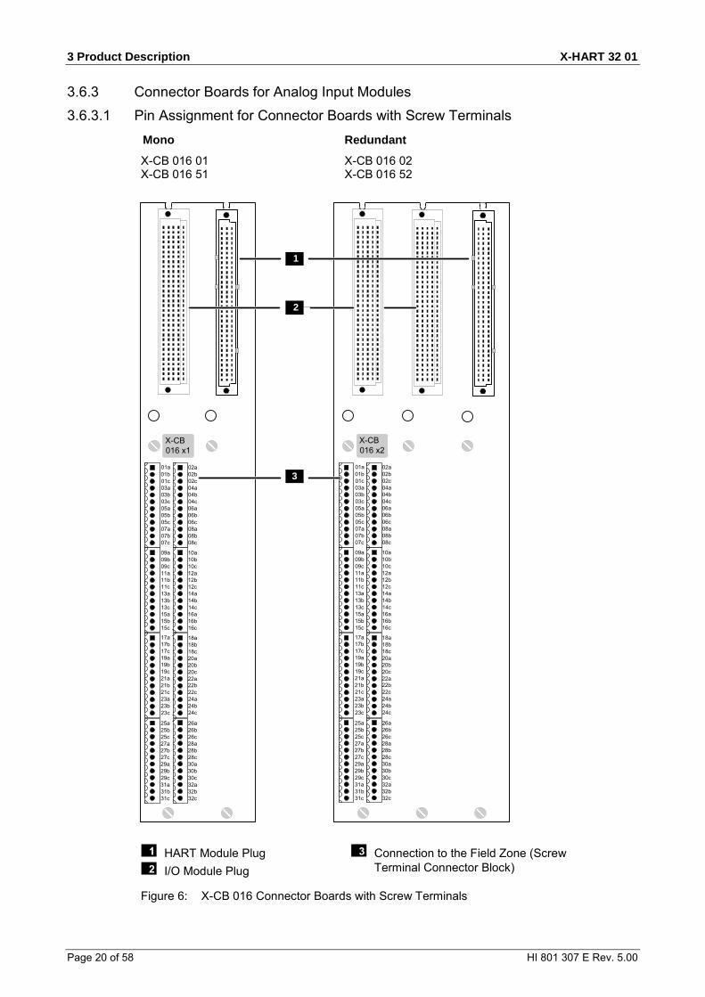
3.6.3 Connector Boards for Analog Input Modules 3.6.3.1 Pin Assignment for Connector Boards with Screw Terminals
Mono Redundant
X-CB 016 01 X-CB 016 02 X-CB 016 51 X-CB 016 52
01a01b01c03a03b03c05a05b05c07a07b07c
02a02b02c04a04b04c06a06b06c08a08b08c
09a09b09c11a11b11c13a13b13c15a15b15c
10a10b10c12a12b12c14a14b14c16a16b16c
17a17b17c19a19b19c21a21b21c23a23b
18a18b18c20a20b20c22a22b22c24a24b24c
25a25b25c27a27b27c29a29b29c31a31b31c
26a26b26c28a28b28c30a30b30c32a32b32c
23c
01a01b01c03a03b03c05a05b05c07a07b07c
02a02b02c04a04b04c06a06b06c08a08b08c
09a09b09c11a11b11c13a13b13c15a15b15c
10a10b10c12a12b12c14a14b14c16a16b16c
17a17b17c19a19b19c21a21b21c23a23b
18a18b18c20a20b20c22a22b22c24a24b24c
25a25b25c27a27b27c29a29b29c31a31b31c
26a26b26c28a28b28c30a30b30c32a32b32c
23c
1
2
X-CB016 x1
X-CB016 x2
3
HART Module Plug I/O Module Plug
Connection to the Field Zone (Screw Terminal Connector Block)
Figure 6: X-CB 016 Connector Boards with Screw Terminals

X-HART 32 01 3 Product Description
HI 801 307 E Rev. 5.00 Page 21 of 58
3.6.3.2 Terminal Assignment for Connector Boards with Screw Terminals Pin no. Designation Signal Pin no. Designation Signal 1 01a S1+ 1 02a S2+ 2 01b AI1+ 2 02b AI2+ 3 01c AI1- 3 02c AI2- 4 03a S3+ 4 04a S4+ 5 03b AI3+ 5 04b AI4+ 6 03c AI3- 6 04c AI4- 7 05a S5+ 7 06a S6+ 8 05b AI5+ 8 06b AI6+ 9 05c AI5- 9 06c AI6- 10 07a S7+ 10 08a S8+ 11 07b AI7+ 11 08b AI8+ 12 07c AI7- 12 08c AI8- Pin no. Designation Signal Pin no. Designation Signal 1 09a S9+ 1 10a S10+ 2 09b AI9+ 2 10b AI10+ 3 09c AI9- 3 10c AI10- 4 11a S11+ 4 12a S12+ 5 11b AI11+ 5 12b AI12+ 6 11c AI11- 6 12c AI12- 7 13a S13+ 7 14a S14+ 8 13b AI13+ 8 14b AI14+ 9 13c AI13- 9 14c AI14- 10 15a S15+ 10 16a S16+ 11 15b AI15+ 11 16b AI16+ 12 15c AI15- 12 16c AI16- Pin no. Designation Signal Pin no. Designation Signal 1 17a S17+ 1 18a S18+ 2 17b AI17+ 2 18b AI18+ 3 17c AI17- 3 18c AI18- 4 19a S19+ 4 20a S20+ 5 19b AI19+ 5 20b AI20+ 6 19c AI19- 6 20c AI20- 7 21a S21+ 7 22a S22+ 8 21b AI21+ 8 22b AI22+ 9 21c AI21- 9 22c AI22- 10 23a S23+ 10 24a S24+ 11 23b AI23+ 11 24b AI24+ 12 23c AI23- 12 24c AI24-

3 Product Description X-HART 32 01
Page 22 of 58 HI 801 307 E Rev. 5.00
Pin no. Designation Signal Pin no. Designation Signal 1 25a S25+ 1 26a S26+ 2 25b AI25+ 2 26b AI26+ 3 25c AI25- 3 26c AI26- 4 27a S27+ 4 28a S28+ 5 27b AI27+ 5 28b AI28+ 6 27c AI27- 6 28c AI28- 7 29a S29+ 7 30a S30+ 8 29b AI29+ 8 30b AI30+ 9 29c AI29- 9 30c AI30- 10 31a S31+ 10 32a S32+ 11 31b AI31+ 11 32b AI32+ 12 31c AI31- 12 32c AI32-
Table 11: Terminal Assignment for Connector Boards with Screw Terminals
Cable plugs attached to the connector board pin headers are used to connect to the field zone.
The cable plugs feature the following properties:
Connection to the field zone Cable plugs 8 pieces, with 12 poles Wire cross-section 0.2…1.5 mm2 (single-wire)
0.2…1.5 mm2 (finely stranded) 0.2…1.5 mm2 (with wire end ferrule)
Stripping length 6 mm Screwdriver Slotted 0.4 x 2.5 mm Tightening torque 0.2…0.25 Nm
Table 12: Cable Plug Properties

X-HART 32 01 3 Product Description
HI 801 307 E Rev. 5.00 Page 23 of 58
3.6.3.3 Pin Assignment for Connector Boards with Cable Plug Mono Redundant
X-CB 016 03 X-CB 016 04 X-CB 016 53 X-CB 016 54
cba
X-CB016 x3
cba
X-CB016 x4
3
4
2
1
5
HART Module Plug I/O Module Plug Connection to the Field Zone (Cable Plug in
Row 1)
Connection to the Field Zone (Cable Plug in Row 32)
Coding for Cable Plugs
Figure 7: X-CB 016 Connector Boards with Cable Plug
3 Product Description X-HART 32 01
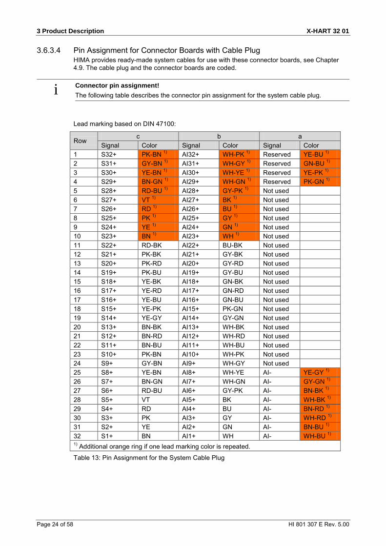
Page 24 of 58 HI 801 307 E Rev. 5.00
3.6.3.4 Pin Assignment for Connector Boards with Cable Plug HIMA provides ready-made system cables for use with these connector boards, see Chapter 4.9. The cable plug and the connector boards are coded.
i Connector pin assignment! The following table describes the connector pin assignment for the system cable plug.
Lead marking based on DIN 47100:
Row c b a
Signal Color Signal Color Signal Color 1 S32+ PK-BN 1) AI32+ WH-PK 1) Reserved YE-BU 1) 2 S31+ GY-BN 1) AI31+ WH-GY 1) Reserved GN-BU 1) 3 S30+ YE-BN 1) AI30+ WH-YE 1) Reserved YE-PK 1) 4 S29+ BN-GN 1) AI29+ WH-GN 1) Reserved PK-GN 1) 5 S28+ RD-BU 1) AI28+ GY-PK 1) Not used 6 S27+ VT 1) AI27+ BK 1) Not used 7 S26+ RD 1) AI26+ BU 1) Not used 8 S25+ PK 1) AI25+ GY 1) Not used 9 S24+ YE 1) AI24+ GN 1) Not used 10 S23+ BN 1) AI23+ WH 1) Not used 11 S22+ RD-BK AI22+ BU-BK Not used 12 S21+ PK-BK AI21+ GY-BK Not used 13 S20+ PK-RD AI20+ GY-RD Not used 14 S19+ PK-BU AI19+ GY-BU Not used 15 S18+ YE-BK AI18+ GN-BK Not used 16 S17+ YE-RD AI17+ GN-RD Not used 17 S16+ YE-BU AI16+ GN-BU Not used 18 S15+ YE-PK AI15+ PK-GN Not used 19 S14+ YE-GY AI14+ GY-GN Not used 20 S13+ BN-BK AI13+ WH-BK Not used 21 S12+ BN-RD AI12+ WH-RD Not used 22 S11+ BN-BU AI11+ WH-BU Not used 23 S10+ PK-BN AI10+ WH-PK Not used 24 S9+ GY-BN AI9+ WH-GY Not used 25 S8+ YE-BN AI8+ WH-YE AI- YE-GY 1) 26 S7+ BN-GN AI7+ WH-GN AI- GY-GN 1) 27 S6+ RD-BU AI6+ GY-PK AI- BN-BK 1) 28 S5+ VT AI5+ BK AI- WH-BK 1) 29 S4+ RD AI4+ BU AI- BN-RD 1) 30 S3+ PK AI3+ GY AI- WH-RD 1) 31 S2+ YE AI2+ GN AI- BN-BU 1) 32 S1+ BN AI1+ WH AI- WH-BU 1) 1) Additional orange ring if one lead marking color is repeated.
Table 13: Pin Assignment for the System Cable Plug

X-HART 32 01 3 Product Description
HI 801 307 E Rev. 5.00 Page 25 of 58
3.6.4 Connector Board for Analog Output Modules 3.6.4.1 Connector Board with Screw Terminals
Mono Redundant
X-CB 017 01 X-CB 017 02 X-CB 017 51
1
2
09a09b11a11b13a13b15a15b
10a10b12a12b14a14b16a16b
01a01b03a03b05a05b07a07b
02a02b04a04b06a06b08a08b
X-CB017 x1
09a09b11a11b13a13b15a15b
01a01b03a03b05a05b07a07b
X-CB017 02
HART Module Plug I/O Module Plug
Connection to the Field Zone (Screw Terminal Connector Block)
Figure 8: Connector Boards with Screw Terminals

3 Product Description X-HART 32 01
Page 26 of 58 HI 801 307 E Rev. 5.00
3.6.4.2 Terminal Assignment for Mono Connector Boards with Screw Terminals Pin no. Designation Signal Pin no. Designation Signal 1 01a AO1+ 1 02a AO2+ 2 01b AO1- 2 02b AO2- 3 03a AO3+ 3 04a AO4+ 4 03b AO3- 4 04b AO4- 5 05a AO5+ 5 06a AO6+ 6 05b AO5- 6 06b AO6- 7 07a AO7+ 7 08a AO8+ 8 07b AO7- 8 08b AO8- Pin no. Designation Signal Pin no. Designation Signal 1 09a AO9+ 1 10a AO10+ 2 09b AO9- 2 10b AO10- 3 11a AO11+ 3 12a AO12+ 4 11b AO11- 4 12b AO12- 5 13a AO13+ 5 14a AO14+ 6 13b AO13- 6 14b AO14- 7 15a AO15+ 7 16a AO16+ 8 15b AO15- 8 16b AO16-
Table 14: Terminal Assignment for Mono Connector Boards with Screw Terminals
Cable plugs attached to the connector board pin headers are used to connect to the field zone.
The cable plugs feature the following properties:
Connection to the field zone Cable plugs 4 pieces, with 8 poles Wire cross-section 0.2…1.5 mm2 (single-wire)
0.2…1.5 mm2 (finely stranded) 0.2…1.5 mm2 (with wire end ferrule)
Stripping length 6 mm Screwdriver Slotted 0.4 x 2.5 mm Tightening torque 0.2…0.25 Nm
Table 15: Cable Plug Properties

X-HART 32 01 3 Product Description
HI 801 307 E Rev. 5.00 Page 27 of 58
3.6.4.3 Terminal Assignment for Redundant Connector Boards with Screw Terminals Pin no. Designation Signal 1 01a AO1+ 2 01b AO1- 3 03a AO3+ 4 03b AO3- 5 05a AO5+ 6 05b AO5- 7 07a AO7+ 8 07b AO7- Pin no. Designation Signal 1 09a AO9+ 2 09b AO9- 3 11a AO11+ 4 11b AO11- 5 13a AO13+ 6 13b AO13- 7 15a AO15+ 8 15b AO15-
Table 16: Terminal Assignment for Redundant Connector Boards with Screw Terminals
Cable plugs attached to the connector board pin headers are used to connect to the field zone.
The cable plugs feature the following properties:
I/O lines Cable plugs 2 pieces, with 8 poles Wire cross-section 0.2…1.5 mm2 (single-wire)
0.2…1.5 mm2 (finely stranded) 0.2…1.5 mm2 (with wire end ferrule)
Stripping length 6 mm Screwdriver Slotted 0.4 x 2.5 mm Tightening torque 0.2…0.25 Nm
Table 17: Cable Plug Properties

3 Product Description X-HART 32 01
Page 28 of 58 HI 801 307 E Rev. 5.00
3.6.4.4 Pin Assignment for Connector Boards with Cable Plug Mono Redundant X-CB 017 03 X-CB 017 04 X-CB 017 53
cba
X-CB017 x3
cba
X-CB017 04
1
3
4
2
5
HART Module Plug I/O Module Plug Connection to the Field Zone
(Cable Plug in Row 1)
Connection to the Field Zone (Cable Plug in Row 32)
Coding for Cable Plugs
Figure 9: X-CB 017 Connector Boards with Cable Plug

X-HART 32 01 3 Product Description
HI 801 307 E Rev. 5.00 Page 29 of 58
3.6.4.5 Pin Assignment for Mono Connector Boards with Cable Plug HIMA provides ready-made system cables for use with this connector board, see Chapter 4.9.
The cable plug and the connector boards are coded.
Lead marking based on DIN 47100:
Row C B a Signal Color Signal Color Signal Color
1 Not used Not used U1-D1A YE-BK 2 Not used Not used U1-D1B GN-BK 3 Not used Not used U1-D2A YE-RD 4 Not used Not used U1-D2B GN-RD 5 Not used Not used 6 Not used Not used 7 Not used Not used 8 Not used Not used 9 Not used Not used 10 Not used Not used 11 Not used Not used 12 Not used Not used 13 Not used Not used 14 Not used Not used 15 Not used Not used 16 Not used Not used 17 AO16+ YE-BU AO16- GN-BU 18 AO15+ YE-PK AO15- PK-GN 19 AO14+ YE-GY AO14- GY-GN 20 AO13+ BN-BK AO13- WH-BK 21 AO12+ BN-RD AO12- WH-RD 22 AO11+ BN-BU AO11- WH-BU 23 AO10+ PK-BN AO10- WH-PK 24 AO9+ GY-BN AO9- WH-GY 25 AO8+ YE-BN AO8- WH-YE 26 AO7+ BN-GN AO7- WH-GN 27 AO6+ RD-BU AO6- GY-PK 28 AO5+ VT AO5- BK 29 AO4+ RD AO4- BU 30 AO3+ PK AO3- GY 31 AO2+ YE AO2- GN 32 AO1+ BN AO1- WH
Table 18: Pin Assignment for Mono Connector Boards with Cable Plug

3 Product Description X-HART 32 01
Page 30 of 58 HI 801 307 E Rev. 5.00
3.6.4.6 Pin Assignment for Redundant Connector Boards with Cable Plug HIMA provides ready-made system cables for use with this connector board, see Chapter 4.9. The cable plug and the connector boards are coded.
Lead marking based on DIN 47100:
Row C b A Signal Color Signal Color Signal Color
1 Not used Not used U1-D1A YE-BK 2 Not used Not used U1-D1B GN-BK 3 Not used Not used U1-D2A YE-RD 4 Not used Not used U1-D2B GN-RD 5 Not used Not used 6 Not used Not used 7 Not used Not used 8 Not used Not used 9 Not used Not used 10 Not used Not used 11 Not used Not used 12 Not used Not used 13 Not used Not used 14 Not used Not used 15 Not used Not used 16 Not used Not used 17 Not used Not used 18 AO15+ YE-PK AO15- PK-GN 19 Not used Not used 20 AO13+ BN-BK AO13- WH-BK 21 Not used Not used 22 AO11+ BN-BU AO11- WH-BU 23 Not used Not used 24 AO9+ GY-BN AO9- WH-GY 25 Not used Not used 26 AO7+ BN-GN AO7- WH-GN 27 Not used Not used 28 AO5+ VT AO5- BK 29 Not used Not used 30 AO3+ PK AO3- GY 31 Not used Not used 32 AO1+ BN AO1- WH
Table 19: Pin Assignment for Redundant Connector Boards with Cable Plug

X-HART 32 01 3 Product Description
HI 801 307 E Rev. 5.00 Page 31 of 58
3.7 System cable
3.7.1 System Cable X-CA 005 The X-CA 005 system cable is used to wire the X-CB 016 03/04 and X-CB 016 53/54 connector boards to the field termination assemblies.
General Cable LIYY-TP 38 x 2 x 0.25 mm² Wire Finely stranded Average outer diameter (d) approx. 15.2 mm Minimum bending radius Fixed laying Flexible application
5 x d 10 x d
Combustion behavior Flame resistant and self-extinguishing in accordance with IEC 60332-1-2, -2-2
Length 8…30 m Color coding Based on DIN 47100, see Table 13.
Table 20: Cable Data
Identical Cable Plugs
Figure 10: System Cable X-CA 001 01 n
The system cable is available in the following standard length:
System cable Description Length X-CA 001 01 8 Coded cable plugs on both sides 8 m X-CA 001 01 15 15 m X-CA 001 01 30 30 m Table 21: Available System Cables
3.7.2 Cable Plug Coding The cable plugs are equipped with three coding pins. Therefore, cable plugs only match connector boards and FTAs encoded accordingly, see Figure 7.
3 Product Description X-HART 32 01
Page 32 of 58 HI 801 307 E Rev. 5.00
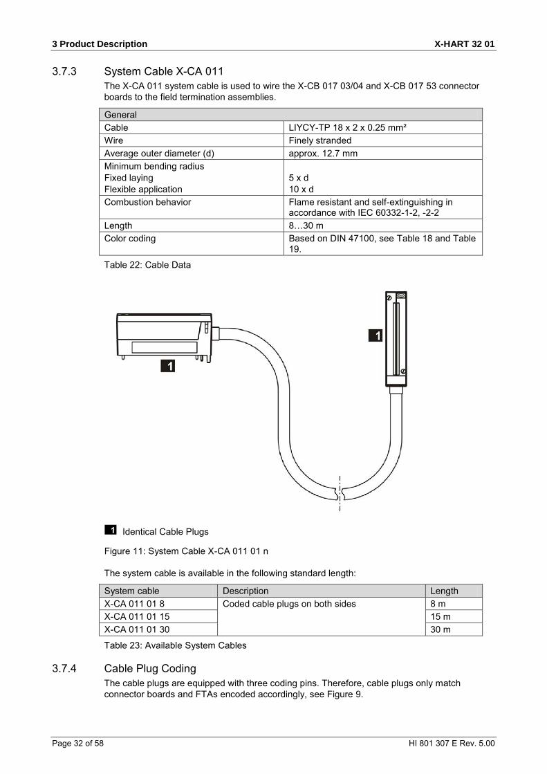
3.7.3 System Cable X-CA 011 The X-CA 011 system cable is used to wire the X-CB 017 03/04 and X-CB 017 53 connector boards to the field termination assemblies.
General Cable LIYCY-TP 18 x 2 x 0.25 mm² Wire Finely stranded Average outer diameter (d) approx. 12.7 mm Minimum bending radius Fixed laying Flexible application
5 x d 10 x d
Combustion behavior Flame resistant and self-extinguishing in accordance with IEC 60332-1-2, -2-2
Length 8…30 m Color coding Based on DIN 47100, see Table 18 and Table
19.
Table 22: Cable Data
Identical Cable Plugs
Figure 11: System Cable X-CA 011 01 n
The system cable is available in the following standard length:
System cable Description Length X-CA 011 01 8 Coded cable plugs on both sides 8 m X-CA 011 01 15 15 m X-CA 011 01 30 30 m
Table 23: Available System Cables
3.7.4 Cable Plug Coding The cable plugs are equipped with three coding pins. Therefore, cable plugs only match connector boards and FTAs encoded accordingly, see Figure 9.

X-HART 32 01 4 Start-up
HI 801 307 E Rev. 5.00 Page 33 of 58
4 Start-up This chapter describes how to install, configure and connect the HART module to the analog input and output modules. For more information, refer to the HIMax manuals for the analog input and output modules and the HIMax Safety Manual (HI 801 003 E).
i The safety-related application (SIL 3 in accordance with IEC 61508) of the inputs and the proximity switches connected must comply with the safety requirements. For more information, refer to the HIMax Safety Manual.
4.1 Mounting Observe the following points when mounting the module:
Only operate the module with the suitable connector board. For more information, see Chapter 4.8.
Only operate the module in parallel with the appropriate analog input or output module. The modules and their connected components must be mounted to provide protection of at
least IP20 in accordance with EN 60529: 1991 + A1: 2000. NOTE
Damage due to incorrect wiring! Failure to comply with these instructions can damage the electronic components. Observe the following points:
Plugs and terminals connected to the field zone. - Take the appropriate earthing measures when connecting the plugs and terminals to the
field zone. - Use shielded cables with twisted pairs. - Connect one twisted pair of the shielded cable to each of the channels. - On the module side, the shielding must be connected to the cable shield rail (use SK 20
shield connection terminal block or similar). - When using stranded wires, HIMA recommends fastening ferrules to the wire ends. The
terminals must be suitable for fastening the cross-sections of the cables in use. If the supply is used, utilize the voltage output used for the assigned channel, see 5.4.1. HIMA recommends using the supply of the analog input module.
If an external supply or measurement unit fails, the affected channel on the module can be overloaded and damaged. If an external supply is required for the given application, check the switching threshold following a non-transient overload that exceeds the limit values of the module.
The analog modules may be wired redundantly using the corresponding connector boards. For more information, see Chapters 4.8 and 5.4.
4.1.1 Wiring I/O Channels Not in Use I/O channels that are not being used may stay open and need not be terminated. To prevent short-circuits and sparks in the field zone, never connect a wire to a connector board if it is open on the field side.

4 Start-up X-HART 32 01
Page 34 of 58 HI 801 307 E Rev. 5.00
4.2 Mounting and Removing the Module When replacing an existing module or mounting a new one, follow the instructions given in this chapter.
When removing the module, the connector board remains in the HIMax base plate. This saves additional wiring effort since all field terminals are connected via the connector board of the module.
4.2.1 Mounting a Connector Board Tools and utilities
Screwdriver, cross PH 1 or slotted 0.8 x 4.0 mm Matching connector board
To install the connector board
1. Insert the connector board into the guiding rail with the groove facing upwards (see following figure). Fit the groove into the guiding rail pin.
2. Place the connector board on the cable shield rail. 3. Secure the captive screws to the base plate. First screw in the lower screws than the upper
ones.
To remove the connector board
1. Release the captive screws from the base plate. 2. Carefully lift the lower section of the connector board from the cable shield rail. 3. Remove the connector board from the guiding rail.
Figure 12: Example of how to Insert the Mono Connector Board

X-HART 32 01 4 Start-up
HI 801 307 E Rev. 5.00 Page 35 of 58
Figure 13: Example of how to Secure the Mono Connector Board with Captive Screws
i These instructions also apply for redundant connector boards. The number of slots used varies in accordance with the connector board type. The number of captive screws depends on the connector board type.

4 Start-up X-HART 32 01
Page 36 of 58 HI 801 307 E Rev. 5.00
4.2.2 Mounting and Removing the Module This chapter describes how to mount and remove the HIMax module. A module can be mounted and removed while the HIMax system is operating.
NOTICE
Damage to bus and power sockets due to module jamming! Failure to observe this can damage the controller. Always take care when inserting the module in the base plate.
Tools and utilities
Screwdriver, slotted 0.8 x 4.0 mm Screwdriver, slotted 1.2 x 8.0 mm
Installation
1. Open the cover plate on the fan rack: Move the locks to the open position. Lift the cover plate and insert into the fan rack
2. Insert the top of the module into the hook-in rail, see . 3. Swivel the lower edge of the module towards the base plate and apply light pressure to snap
it into place, see . 4. Tighten the screws, see . 5. Pull the cover plate out of the fan rack and close it. 6. Lock the cover plate.
Removal
1. Open the cover plate on the fan rack: Move the locks to the open position. Lift the cover plate and insert into the fan rack
2. Release the screw . 3. Swivel the lower edge of the module away from the base plate. Lift and apply light pressure
to remove the module from the hook-in rail, see and . 4. Pull the cover plate out of the fan rack and close it. 5. Lock the cover plate.

X-HART 32 01 4 Start-up
HI 801 307 E Rev. 5.00 Page 37 of 58
Inserting and Removing a Module Swiveling a Module in and out
Securing and Releasing a Module
Figure 14: Mounting and Removing a Module
i If the HIMax system is operating, do not open the cover plate of the fan rack for more than a few minutes (< 10 min) since this affects the forced cooling.

4 Start-up X-HART 32 01
Page 38 of 58 HI 801 307 E Rev. 5.00
4.3 Configuring the Module in SILworX The module is configured in the Hardware Editor of the SILworX programming tool.
Observe the following points when configuring the module:
Configure the corresponding analog input or output module in SILworX. To diagnose the module and channels, the system parameters can be evaluated within the
user program. For more information on the system parameters, refer to the tables starting with Chapter 5.3.
In case of analog output redundancy, the Module Status parameter must be additionally taken into account, see HI 801 111 E.
If short-circuits or open-circuits occur, no HART communication is possible. Under these conditions, the requests or settings performed through HART communication must be rejected.
To evaluate the statuses from within the user program, assign the module statuses global variables. Perform this step in the Hardware Editor using the module's detail view.
The following tables present the statuses and parameters for the module in the same order given in the Hardware Editor.
TIP To convert hexadecimal values to bit strings a scientific calculator such as the Windows® calculator with the corresponding view can be used.

X-HART 32 01 4 Start-up
HI 801 307 E Rev. 5.00 Page 39 of 58
4.3.1 Tab: Module The Module tab contains the statuses and parameters for the module.
Name R/W Description Enter these statuses and parameters directly in the Hardware Editor. Name W Module name Noise Blanking W Noise blanking performed by processor module allowed
(activated/deactivated). Default setting: Activated The processor modules defers the reaction to detected transient faults until the safety time has expired. The user program retains its last valid process value.
Name Data type R/W Description The following statuses and parameters can be assigned global variables and used in the user program. Module OK BOOL R TRUE:
No module fault. FALSE: Module fault Channel fault (no external faults), the module is not inserted. Observe the Module Status parameter!
Module Status DWORD R Status of the module Coding Description 0x00000001 Module fault 1) 0x00000002 Temperature threshold 1 exceeded 0x00000004 Temperature threshold 2 exceeded 0x00000008 Incorrect temperature value 0x00000010 Voltage on L1+ is defective 0x00000020 Voltage on L2+ is defective 0x00000040 Internal voltage is defective 0x80000000 No connection to the module 1) 1) These faults affect the Module OK status and need
not be separately evaluated in the user program.
Timestamp [µsec] DWORD R Microsecond fraction of the timestamp. Point in time at which the channel measurement was performed.
Timestamp [s] DWORD R Second fraction of the timestamp. Point in time at which the channel measurement was performed.
Table 24: Module Tab in the Hardware Editor
4 Start-up X-HART 32 01
Page 40 of 58 HI 801 307 E Rev. 5.00
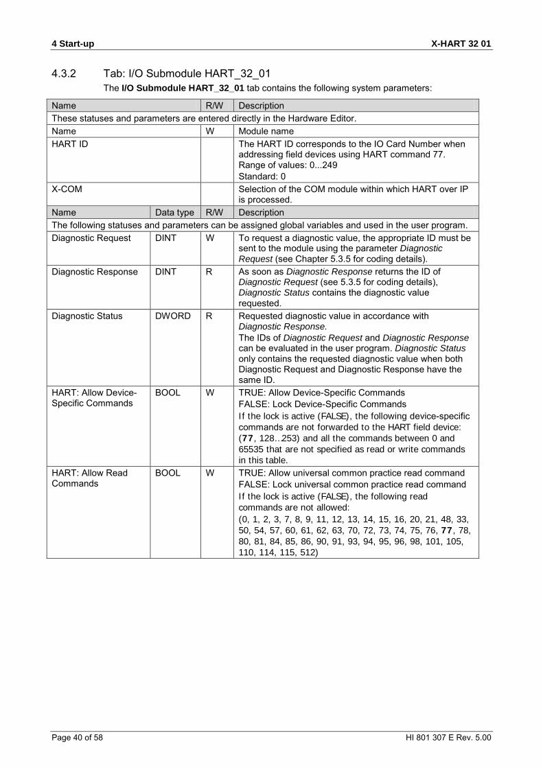
4.3.2 Tab: I/O Submodule HART_32_01 The I/O Submodule HART_32_01 tab contains the following system parameters:
Name R/W Description These statuses and parameters are entered directly in the Hardware Editor. Name W Module name HART ID The HART ID corresponds to the IO Card Number when
addressing field devices using HART command 77. Range of values: 0...249 Standard: 0
X-COM Selection of the COM module within which HART over IP is processed.
Name Data type R/W Description The following statuses and parameters can be assigned global variables and used in the user program. Diagnostic Request DINT W To request a diagnostic value, the appropriate ID must be
sent to the module using the parameter Diagnostic Request (see Chapter 5.3.5 for coding details).
Diagnostic Response DINT R As soon as Diagnostic Response returns the ID of Diagnostic Request (see 5.3.5 for coding details), Diagnostic Status contains the diagnostic value requested.
Diagnostic Status DWORD R Requested diagnostic value in accordance with Diagnostic Response. The IDs of Diagnostic Request and Diagnostic Response can be evaluated in the user program. Diagnostic Status only contains the requested diagnostic value when both Diagnostic Request and Diagnostic Response have the same ID.
HART: Allow Device-Specific Commands
BOOL W TRUE: Allow Device-Specific Commands FALSE: Lock Device-Specific Commands If the lock is active (FALSE), the following device-specific commands are not forwarded to the HART field device: (77, 128…253) and all the commands between 0 and 65535 that are not specified as read or write commands in this table.
HART: Allow Read Commands
BOOL W TRUE: Allow universal common practice read command FALSE: Lock universal common practice read command If the lock is active (FALSE), the following read commands are not allowed: (0, 1, 2, 3, 7, 8, 9, 11, 12, 13, 14, 15, 16, 20, 21, 48, 33, 50, 54, 57, 60, 61, 62, 63, 70, 72, 73, 74, 75, 76, 77, 78, 80, 81, 84, 85, 86, 90, 91, 93, 94, 95, 96, 98, 101, 105, 110, 114, 115, 512)

X-HART 32 01 4 Start-up
HI 801 307 E Rev. 5.00 Page 41 of 58
HART: Allow Write Commands
BOOL W TRUE: Allow universal common practice write command FALSE: Lock universal common practice write command If the lock is active (FALSE), the following write commands are not forwarded to the HART field device: (6, 17, 18, 19, 22, 38, 34, 35, 36, 37, 39, 40, 41, 42, 43, 44, 45, 46, 47, 49, 51, 52, 53, 55, 56, 58, 59, 64, 65, 66, 67, 68, 69, 71, 77, 79, 82, 83, 87, 88, 89, 92, 97, 99, 102, 103, 104, 106, 107, 108, 109, 111, 112, 113, 116, 117, 118, 119, 513)
Background Test Error BOOL R TRUE: Background test is faulty FALSE: Background test is free of faults
Restart on Error BOOL W Using the parameter Restart on Error, each I/O module that has switched off permanently due to faults can be forced to re-adopt the RUN state. To do this, set the Restart on Error parameter FALSE to TRUE. The I/O module performs a complete self-test and only enters the RUN state if no faults are detected. Default setting: FALSE
Submodule OK BOOL R TRUE: No submodule fault. No channel faults FALSE: Submodule fault. Channel fault (external faults included)
Submodule Status BOOL R Bit-coded submodule status (see 5.3.4 for coding details)
Table 25: Tab I/O Submodule HART_32_01 in the Hardware Editor

4 Start-up X-HART 32 01
Page 42 of 58 HI 801 307 E Rev. 5.00
4.3.3 Tab: I/O Submodule HART_32_01: Channels The I/O Submodule HART_32_01:Channels tab contains the following system parameters for each HART channel. Global variables can be assigned to the statuses and parameters with -> and used in the user program. The value without -> must be directly entered.
Name Data type R/W Description Channel no. --- R Channel number, defined by default -> Channel OK BOOL R TRUE: Faultless channel
FALSE: Faulty channel Activate HART [BOOL] -> BOOL W Activate/deactivate HART communication for this
channel
Table 26: Tab I/O Submodule HART_32_01:Channels in the Hardware Editor
4.3.4 Submodule Status [DWORD] Coding of the variable Submodule Status.
Coding Description 0x00000008 Fault detected while initializing the module 0x00000080 Chip select monitoring time 0x00020000 Warning, deviation of internal voltage measurement 0x00100000 Deviation of the HART clock to the internal 33 MHz clock 0x00200000 Deviation of the 33 MHz clock 0x00400000 Defective voltage monitoring 0x00800000 Internal voltage on 3V4 is defective 0x01000000 Internal voltage on 1V8 is defective 0x02000000 Internal voltage on 1V2 is defective 0x04000000 Internal voltage on 3V3 is defective 0x08000000 Internal voltage on GND is defective 0x10000000 Internal voltage on SI1 is defective 0x20000000 Internal voltage on SI2 is defective 0x40000000 Internal voltage on MES_WD is defective
Table 27: Submodule Status [DWORD]

X-HART 32 01 4 Start-up
HI 801 307 E Rev. 5.00 Page 43 of 58
4.3.5 Diagnostic Status [DWORD] Coding of the variable Diagnostic Status.
ID Description 0 Diagnostic values are indicated consecutively. 100 Bit-coded temperature status
0 = normal Bit0 = 1 : Temperature threshold 1 has been exceeded Bit1 = 1 : Temperature threshold 2 has been exceeded Bit2 = 1 : Fault in temperature measurement
101 Measured temperature (10 000 digits/ °C) 200 Bit-coded voltage status
0 = normal Bit0 = 1 : L1+ (24 V) is faulty Bit1 = 1 : L2+ (24 V) is faulty
201 Not used! 202 203 300 Comparator 24 V undervoltage (BOOL) 1001…1032 Status of the channels 1...32
Coding Description 0x0001 Error during internal tests, see Chapter 5.3.4 0x0008 Internal fault occurred while controlling the channel switches
(corrupted to 0) 0x0040 Internal fault occurred while controlling the channel switches
(corrupted to 1) 0x0100 HART communication error or no device found 0x0200 Warning, internal deviation occurred while controlling the channel
switches 0x0400 Defective sending of HART data 0x0800 Defective channel RTS signal 0x1000 Defective channel Rx signal 0x2000 Defective channel Tx signal 0x4000 Defective HART clock reading back 0x8000 Channel cannot be opened.
Table 28: Diagnostic Information [DWORD]
4 Start-up X-HART 32 01
Page 44 of 58 HI 801 307 E Rev. 5.00
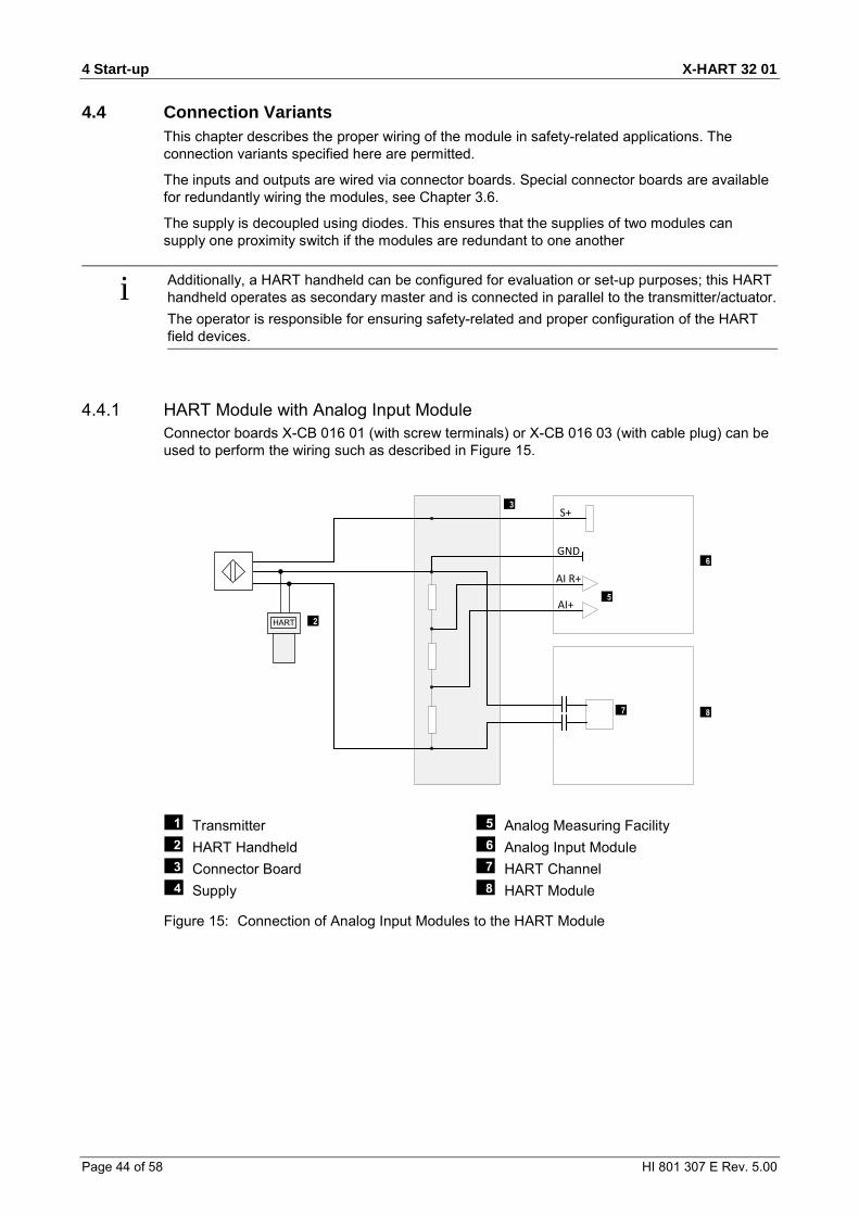
4.4 Connection Variants This chapter describes the proper wiring of the module in safety-related applications. The connection variants specified here are permitted.
The inputs and outputs are wired via connector boards. Special connector boards are available for redundantly wiring the modules, see Chapter 3.6.
The supply is decoupled using diodes. This ensures that the supplies of two modules can supply one proximity switch if the modules are redundant to one another
i Additionally, a HART handheld can be configured for evaluation or set-up purposes; this HART handheld operates as secondary master and is connected in parallel to the transmitter/actuator. The operator is responsible for ensuring safety-related and proper configuration of the HART field devices.
4.4.1 HART Module with Analog Input Module Connector boards X-CB 016 01 (with screw terminals) or X-CB 016 03 (with cable plug) can be used to perform the wiring such as described in Figure 15.
S+
GND
AI R+
AI+HART
Transmitter HART Handheld Connector Board Supply
Analog Measuring Facility Analog Input Module HART Channel HART Module
Figure 15: Connection of Analog Input Modules to the HART Module

X-HART 32 01 4 Start-up
HI 801 307 E Rev. 5.00 Page 45 of 58
4.4.2 HART Module with Redundant Analog Input Modulesn When redundantly wired as specified in Figure 16, the analog input modules and the HART module are inserted in the base plate next to each other and on a common connector board.
Connector boards X-CB 016 02 (with screw terminals) or X-CB 016 04 (with cable plug) can be used.
S+
GND
AI R+
AI+
S+
GND
AI R+
AI+
Transmitter Connector Board Supply Analog Measuring Facility
Analog Input Module HART Channel HART Module
Figure 16: Redundant Connection of Analog Input Modules to the HART Module

4 Start-up X-HART 32 01
Page 46 of 58 HI 801 307 E Rev. 5.00
4.4.3 HART Module with Analog Output Module Connector boards X-CB 017 01 (with screw terminals) or X-CB 017 03 (with cable plug) can be used to perform the wiring such as described in Figure 15.
AO1+
AO1-
Analog Output Module Connector Board Actuator (Load)
HART Module HART Channel Analog Output
Figure 17: Connection of Analog Output Modules to the HART Module

X-HART 32 01 4 Start-up
HI 801 307 E Rev. 5.00 Page 47 of 58
4.4.4 HART Module with Redundant Analog Output Modules When redundantly wired as specified in Figure 18, the analog output modules and the HART module are inserted in the base plate next to each other and on a common connector board.
Connector boards X-CB 017 02 (with screw terminals) or X-CB 017 04 (with cable plug) can be used.
AO1+
AO1-
AO1+
AO1-
Analog Output Module Connector Board Actuator (Load)
HART Module HART Channel Analog Output
Figure 18: Redundant Connection of Analog Output Modules to the HART Module

5 Operation X-HART 32 01
Page 48 of 58 HI 801 307 E Rev. 5.00
5 Operation The module runs within a HIMax base plate and does not require any specific monitoring.
5.1 Handling Direct handling of the module is not foreseen.
The module and submodule are operated from within the PADT. For more details, refer to the SILworX documentation.
5.2 Diagnosis LEDs on the front side of the module indicate the module state, see Chapter 4.6.2.
The diagnostic history of the module can also be read using SILworX. Chapter 5.3.4 and Chapter 5.3.5 describe the most important diagnostic statuses.
i If a module is plugged in to a base plate, it generates diagnostic messages during its initialization phase indicating faults such as incorrect voltage values. These messages only indicate a module fault if they occur after the system starts operation.

X-HART 32 01 6 Maintenance
HI 801 307 E Rev. 5.00 Page 49 of 58
6 Maintenance Defective modules must be replaced with a faultless module of the same type or with an approved replacement model.
Only the manufacturer is authorized to repair the module.
When replacing modules, observe the instructions specified in the System Manual (HI 801 001 E) and Safety Manual (HI 801 003 E).
6.1 Maintenance Measures
6.1.1 Loading the Operating System HIMA is continuously improving the operating system of the module. HIMA recommends to use system downtimes to load the current version of the operating system into the module.
For detailed instructions on how to load the operating system, see the system manual and the online help. The module must be in STOP to be able to load an operating system.
i The current version of the module in use is displayed in the SILworX Control Panel! The type label specifies the version when the module is delivered, see Chapter 3.3.
6.1.2 Proof Test HIMax modules must be subjected to a proof test in intervals of 10 years. For more information, refer to the Safety Manual HI 801 003 E.

7 Decommissioning X-HART 32 01
Page 50 of 58 HI 801 307 E Rev. 5.00
7 Decommissioning To decommission the module, remove it from the base plate. For more information, see Mounting and Removing the Module.

X-HART 32 01 8 Transport
HI 801 307 E Rev. 5.00 Page 51 of 58
8 Transport To avoid mechanical damage, HIMax components must be transported in packaging.
Always store HIMax components in their original product packaging. This packaging also provides protection against electrostatic discharge. Note that the product packaging alone is not suitable for transport.
9 Disposal X-HART 32 01
Page 52 of 58 HI 801 307 E Rev. 5.00
9 Disposal Industrial customers are responsible for correctly disposing of decommissioned HIMax hardware. Upon request, a disposal agreement can be arranged with HIMA.
All materials must be disposed of in an ecologically sound manner.

X-HART 32 01 9 Disposal
HI 801 307 E Rev. 5.00 Page 53 of 58

Appendix X-HART 32 01
Page 54 of 58 HI 801 307 E Rev. 5.00
Appendix Glossary Term Description ARP Address Resolution Protocol: Network protocol for assigning the network addresses
to hardware addresses AI Analog Input Connector Board Connector board for the HIMax module COM Communication module CRC Cyclic Redundancy Check DI Digital Input DO Digital Output EMC Electromagnetic Compatibility EN European Norm ESD ElectroStatic Discharge FB Fieldbus FBD Function Block Diagram FTT Fault Tolerance Time ICMP Internet Control Message Protocol: Network protocol for status or error messages IEC International Electrotechnical Commission MAC address Hardware address of one network connection (Media Access Control) PADT Programming And Debugging Tool (in accordance with IEC 61131-3),
PC with SILworX PE Protective Earth PELV Protective Extra Low Voltage PES Programmable Electronic System PFD Probability of Failure on Demand, probability of failure on demand of a safety
function PFH Probability of Failure per Hour, probability of a dangerous failure per hour R Read Rack ID Base plate identification (number) Non-reactive Supposing that two input circuits are connected to the same source (e.g., a
transmitter). An input circuit is termed "non-reactive" if it does not distort the signals of the other input circuit.
R/W Read/Write SB System Bus (Module) SELV Safety Extra Low Voltage SFF Safe Failure Fraction, portion of safely manageable faults SIL Safety Integrity Level (in accordance with IEC 61508) SILworX Programming tool for HIMax SNTP Simple Network Time Protocol (RFC 1769) SRS System.Rack.Slot addressing of a module SW Software TMO TiMeOut TMR Triple Module Redundancy W Write rP Peak value of a total AC component Watchdog (WD) Time monitoring for modules or programs. If the watchdog time is exceeded, the
module or program enters the ERROR STOP state. WDT WatchDog Time

X-HART 32 01 Appendix
HI 801 307 E Rev. 5.00 Page 55 of 58
Index of Figures Figure 1: Sample Type Label 11
Figure 2: Block Diagram 12
Figure 3: Indicators 13
Figure 4: Views 16
Figure 5: Coding Example 19
Figure 6: X-CB 016 Connector Boards with Screw Terminals 20
Figure 7: X-CB 016 Connector Boards with Cable Plug 23
Figure 8: Connector Boards with Screw Terminals 25
Figure 9: X-CB 017 Connector Boards with Cable Plug 28
Figure 10: System Cable X-CA 001 01 n 31
Figure 11: System Cable X-CA 011 01 n 32
Figure 12: Example of how to Insert the Mono Connector Board 34
Figure 13: Example of how to Secure the Mono Connector Board with Captive Screws 35
Figure 14: Mounting and Removing a Module 37
Figure 15: Connection of Analog Input Modules to the HART Module 44
Figure 16: Redundant Connection of Analog Input Modules to the HART Module 45
Figure 17: Connection of Analog Output Modules to the HART Module 46
Figure 18: Redundant Connection of Analog Output Modules to the HART Module 47

Appendix X-HART 32 01
Page 56 of 58 HI 801 307 E Rev. 5.00
Index of Tables Table 1: Additional Valid Manuals 5
Table 2: Environmental Requirements 8
Table 3: Blinking Frequencies of LEDs 14
Table 4: Module Status Indicators 14
Table 5: System Bus Indicators 15
Table 6: I/O Indicators LEDs 15
Table 7: Product Data 16
Table 8: Specifications for the HART Channels 17
Table 9: Available Connector Boards 18
Table 10: Position of Coding Wedges on HART Module Slot 19
Table 11: Terminal Assignment for Connector Boards with Screw Terminals 22
Table 12: Cable Plug Properties 22
Table 13: Pin Assignment for the System Cable Plug 24
Table 14: Terminal Assignment for Mono Connector Boards with Screw Terminals 26
Table 15: Cable Plug Properties 26
Table 16: Terminal Assignment for Redundant Connector Boards with Screw Terminals 27
Table 17: Cable Plug Properties 27
Table 18: Pin Assignment for Mono Connector Boards with Cable Plug 29
Table 19: Pin Assignment for Redundant Connector Boards with Cable Plug 30
Table 20: Cable Data 31
Table 21: Available System Cables 31
Table 22: Cable Data 32
Table 23: Available System Cables 32
Table 24: Module Tab in the Hardware Editor 39
Table 25: Tab I/O Submodule HART_32_01 in the Hardware Editor 41
Table 26: Tab I/O Submodule HART_32_01:Channels in the Hardware Editor 42
Table 27: Submodule Status [DWORD] 42
Table 28: Diagnostic Information [DWORD] 43
X-HART 32 01 Appendix
HI 801 307 E Rev. 5.00 Page 57 of 58
Index block diagram ............................................ 12 connector board ......................................... 18
with screw terminals ............................... 25 with screw terminals ............................... 20
diagnosis ................................................... 48 I/O indicators .......................................... 15
system bus indicators ............................. 15 module status indicators ............................ 14 safety function ............................................ 10 specifications
HART channels ...................................... 17 module ................................................... 16

HI 801 307 E © 2012 HIMA Paul Hildebrandt GmbH + Co KG HIMax and SILworX are registered trademark of: HIMA Paul Hildebrandt GmbH + Co KG Albert-Bassermann-Str. 28 68782 Brühl, Germany Phone +49 6202 709-0 Fax +49 6202 709-107 [email protected] www.hima.com