X-Band EPRProbe Loop Gap Resonator - molspec.com ELEXSYS MANUAL.pdf · SECTION 1 About Molecular...
47
Loop Gap Resonator X-Band EPR Probe Molecular Specialties, Inc. 10437 Innovation Drive, Suite 301 Milwaukee, WI 53226 Phone: 414-258-6724 Fax: 414-727-9578 Contact: Richard J. Stevens, President & CEO E-mail: [email protected] Web: www.molspec.com Operator’s Manual Version 5.0-A For the Bruker ELEXSYS E 500 spectrometer (Catalog No. XP-0201)
-
Upload
nguyenkhue -
Category
Documents
-
view
221 -
download
1
Transcript of X-Band EPRProbe Loop Gap Resonator - molspec.com ELEXSYS MANUAL.pdf · SECTION 1 About Molecular...
Loop Gap ResonatorX-Band EPR Probe
Molecular Specialties, Inc.10437 Innovation Drive, Suite 301Milwaukee, WI 53226Phone: 414-258-6724Fax: 414-727-9578Contact: Richard J. Stevens, President & CEOE-mail: [email protected]: www.molspec.com
Operator’s Manual Version 5.0-AFor the Bruker ELEXSYS
E 500 spectrometer
(Catalog No. XP-0201)

SECTION 1About Molecular Specialties, Inc.
Table of ContentsPAGE 2
SECTION 2Your Loop Gap Resonator
SECTION 3I n s t a l l a t i o n
SECTION 4Preparing Test Samples
1.1 About Molecular Specialties, Inc. 51.2 Welcome! 6
3.1 Installation 14
2.1 Your Loop Gap Resonator 72.2 Technical Data 82.3 Optimal Experiments 92.4 The Basics 102.5 Preventive Maintenance 12
Part 1 Cleaning 12Part 2 Proper Handling 13
4.1 Preparing Test Samples 18Part 1 Preparing a TPX Capillary 19Part 2 Preparing a Glass Tube 22
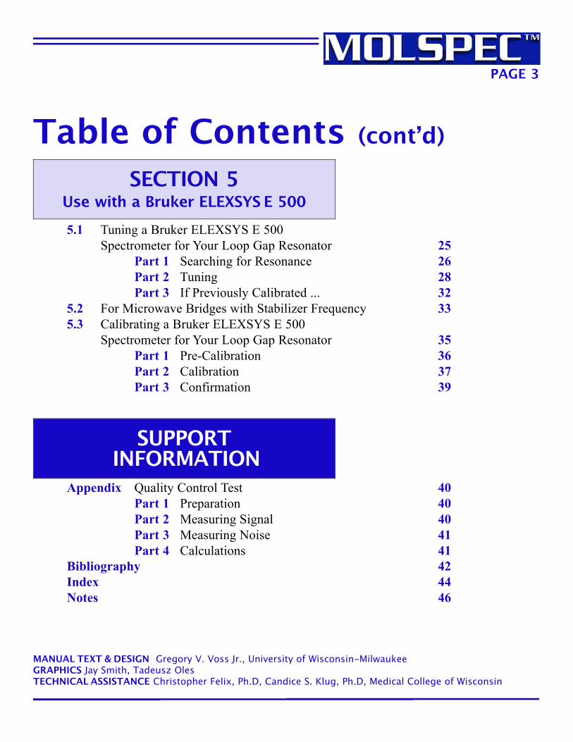
Table of Contents (cont’d)
PAGE 3
SECTION 5Use with a Bruker ELEXSYS E 500
S U P P O R TI N F O R M A T I O N
5.1 Tuning a Bruker ELEXSYS E 500Spectrometer for Your Loop Gap Resonator 25
Part 1 Searching for Resonance 26Part 2 Tuning 28Part 3 If Previously Calibrated ... 32
5.2 For Microwave Bridges with Stabilizer Frequency 335.3 Calibrating a Bruker ELEXSYS E 500
Spectrometer for Your Loop Gap Resonator 35Part 1 Pre-Calibration 36Part 2 Calibration 37Part 3 Confirmation 39
Appendix Quality Control Test 40Part 1 Preparation 40Part 2 Measuring Signal 40Part 3 Measuring Noise 41Part 4 Calculations 41
Bibliography 42Index 44Notes 46
MANUAL TEXT & DESIGN Gregory V. Voss Jr., University of Wisconsin-MilwaukeeGRAPHICS Jay Smith, Tadeusz OlesTECHNICAL ASSISTANCE Christopher Felix, Ph.D, Candice S. Klug, Ph.D, Medical College of Wisconsin
TROUBLESHOOTING
TIPTrouble Shooting Tip boxes will help you overcome any issues or problemsyou may encounter while using your Loop Gap Resonator.
Handy Tip boxes are designed toprovide “tricks of the trade” that willhelp you use your Loop Gap Resonatorand its accessories more efficiently.
HANDY TIP
Helps and Hints
PAGE 4
The following conventions are designed to optimize use of this manual and yourLoop Gap Resonator.
Click on any section header, located in theupper right corner of each page, to returnto the Table of Contents.
Click on any page reference to go directly to that page.
See Page 5.
SECTION 1.1
General
PDF Format Navigation
SECTION 1.1
About Molecular Specialties, Inc.
PAGE 5
Molecular Specialties, Inc. designs, manufactures, and sells EPR-relatedproducts, including modulation coils and probes. Its products serve aworldwide market, and engage the biophysics and molecular/cellularchemistry laboratories of academic institutions.
For Further Information, ContactMolecular Specialties, Inc.10437 Innovation Drive, Suite 301Milwaukee, WI 53226Contact: Richard J. Stevens, President & CEOPhone: 414-258-6724Fax: 414-727-9578E-mail: [email protected]: www.molspec.com
If you are ordering a Loop Gap Resonator, you will need to provide several pieces of information toMolecular Specialties so you will receive a unit that is designed specifically for your lab’s needs.Required information includes:
• The exact make/model of the spectrometer(s) with which your Loop Gap Resonator will be used.
• The exact distance between the tabletop (where the microwave bridge typically rests) and the center of the magnet pole pieces.
• The exact distance between the magnet pole pieces (or the pole gap).
• The position of the Hall Probe.
• The resonant frequency range of your microwave bridge(s).
Standard delivery is 60 days after receipt of order with deposit, unless stated otherwise. Shipping dates are approximate and are based onprompt receipt of all necessary information.
Pricing does not include sales, use, excise, or similar taxes. All financing plans must be accompanied by a suitable security agreementacceptable to Molecular Specialties, Inc.
If You Are Ordering ...

Congratulations on the purchase of your X-Band Loop Gap Resonator!
Its very high sensitivity, strong RF magnetic field, and high resonator efficiencyparameter make it the perfect upgrade from the traditional cavity resonators foundon most EPR spectrometers. Its features will maximize your research potential:
• Outstanding sensitivity, making it the choice for small samples.
• Control and change of oxygen content without removing the sample from the resonator piece, when using Molecular Specialties’ TPXCapillary, achieved by affixing a hose to the hose barb and blowing gas with different oxygen content past the sample.
• High filling factor, crucial for EPR pulse experiments and continuous-wave saturation studies on transition-metal ions.
• Low Q Factor – 600 unloaded – which lessens the susceptibility of the structure to demodulation of source noise, microphonics, and vibrations.Note: The measured Q of a matched resonator is, by definition, the loaded Q. It is half of the Q of a cavity that has no coupling structure. The word “loaded” is sometimes used to imply that a sample has been introduced.
• Modification capability, allowing it to operate with a stop-flow apparatus.
• Temperature control, through hot or cold gas flow via a dewar that fits over the resonator piece but does not interfere with the modulation coil.
Welcome!
Warranty
PAGE 6
Your Loop Gap Resonator is warranted to be free from defects in materials and workmanship forone year, unless otherwise stated, from shipment date. For more information, contact MolecularSpecialties. See Page 5.
SECTION 1.2
PAGE 7
Your Loop Gap Resonator
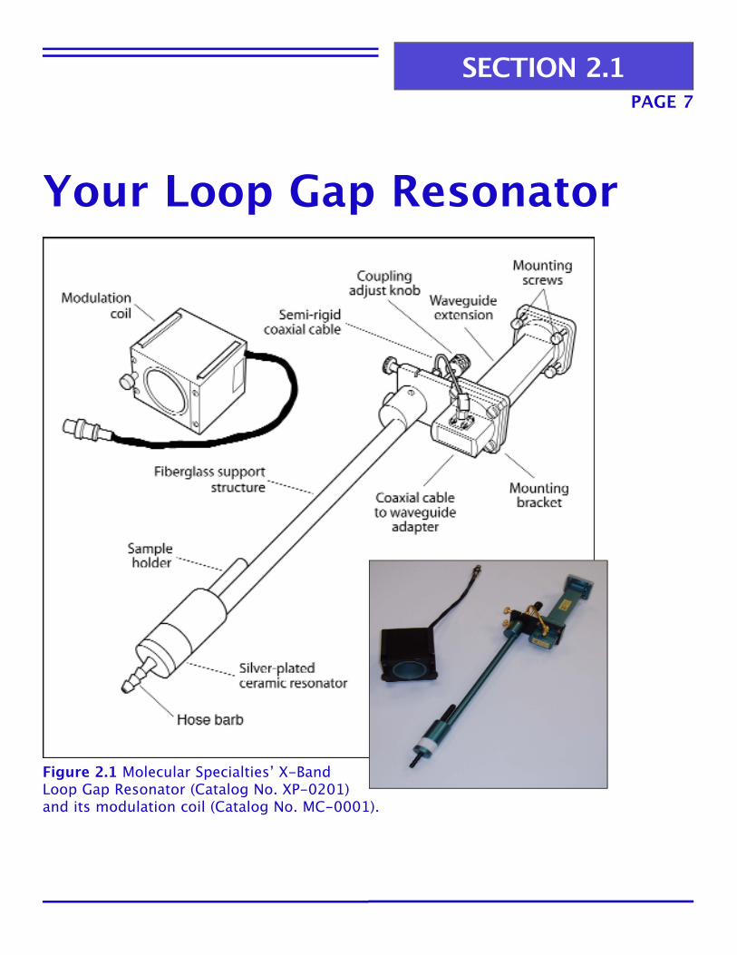
Figure 2.1 Molecular Specialties’ X-BandLoop Gap Resonator (Catalog No. XP-0201)and its modulation coil (Catalog No. MC-0001).
SECTION 2.1

Technical Data
PAGE 8
Resonant Frequency Range 8.5-10.0 GHz (specified by customer)
Q (Quality Factor) Value 600 unloaded
Modulation Coil Capability 12.5-100 KHz modulation fields
Overall Length 41.0cm/14.7637 inches
Loop Diameter 1.0mm/0.039 inches
Loop Length 5.0mm/0.196 inches
Loop Volume 3.9 µL
Recommended Sample Tubes Glass tube, TPX Capillary
Frequency Shift 80 MHz (0.6mm i.d. aqueous sample)
Optimum diameter/aqueous sample 0.6mm/0.023 inches
Outside diameter of probe 23.0mm/0.905 inches
Maximum sample tube outside diameter 0.9mm/0.035 inches
Distance from resonator towaveguide flange (with 11.5cm waveguide) 37.5cm/14.7637 inches
Temperature range Liquid nitrogen to 60 C
Minimum performance specifications Signal-to-noise 1,500 (10 µM Tempone sample in 0.6mm i.d. glass tube,2.5 mW sample arm power, 100 kHz modulation;see quality control test on Page 40.)
SECTION 2.2
o

PAGE 9
Optimal ExperimentsYour X-Band Loop Gap Resonator is a great choice for a wide range of EPR applications, including:
• Experiments where the sample is in limited quantity, such as site-directed spin-labeling of a protein where only a few microliters of test material is available.
• Experiments where you desire higher effective microwave power at the sample, such as EPR pulse experiments.
• Experiments where you wish to utilize multiple microwave frequenciessimultaneously.
• Experiments where you require a lower Q (Quality) Factor to reduce “ringing.”
• Continuous-wave saturation experiments.
• Stop-flow studies.
Note: If you are planning to do stop-flow studies, contactUpdate Instruments, Inc., to acquire the proper hardware:
Update Instruments, Inc.6701 Seybold RoadMadison, WI 53719Contact: Wayne MuellerPhone: 608-274-6960
SECTION 2.3

PAGE 10
The BasicsThe key to your Loop Gap Resonator is the resonator piece itself, which is foundat the end of the fiberglass support structure.
The resonator piece is constructed of a ceramic material that contains twocylindrical holes (or loops) connected by a slot (or a gap).
The internal surface of the ceramic cylinder is coated with a thin layer of silver.The microwave electric field is mainly concentrated within the slot, while themagnetic flux is concentrated within the holes.
See Figure 2.2 for a detailed schematic of this process and a photo of theresonator piece.
Figure 2.2 The inner operation ofyour Loop Gap Resonator’s resonatorpiece.
SECTION 2.4

PAGE 11
A glass tube or Molecular Specialties’ TPX Capillary (Catalog No. TPX-2)containing your sample (either aqueous or non-aqueous) is placed within the sample loop via the resonator’s sample holder or Molecular Specialties’ TPXHolder (Catalog No. TPX H-2), respectively.
The magnetic flux density to which the sample is exposed in the resonator piece is greater than an air-filled cavity operating at the same frequency.
SECTION 2.4

Preventive Maintenance
Your Loop Gap Resonator must be kept extremely clean as contamination willgreatly limit its performance. Heeding the following tips will greatly enhance itsperformance and lifespan.
• Do not brush the interior of the resonator piece. Doing so could scratch or damage its silver coating.
• Do not use compressed air when cleaning. Compressed air may contain fine particles of dust or droplets of water or oil that could damage theresonator piece.
• Do not use solvents such as acetone when cleaning. Doing so could damage the finish and materials from which the support structure isfabricated.
• Pure liquid contaminants may be removed by rinsing with pure wateror ethanol, followed by a purge of nitrogen gas. However,evaporation of solvents from a solution will leave a solute residue.
PAGE 12
TROUBLESHOOTING
TIPYou should not attempt to repair ordisassemble your Loop Gap Resonator.Doing so will void your warranty.Contact Molecular Specialties forservice and repair information.See Page 5.
SECTION 2.5
Part 1 – Cleaning

PAGE 13
It is imperative you exhibit more than ordinary care in handling samples whenusing your Loop Gap Resonator. Its small dimensions and precision machiningmake contamination removal difficult and could ultimately require complete disassembly by Molecular Specialties, Inc.
Heeding the following tips when handling samples will result in more successful experiments.
• Do not forcibly insert or remove sample tubes from the resonator piece.
• Do not turn the coupling adjust knob (the iris) past its limits.See Figure 2.3. Doing so could damage the coupling loop and prevent correct operation. Damage to the coupling loop may appear as excessive baseline noise, or “jitter.”
SECTION 2.5
Part 2 – Proper Handling
• Avoid sharp edges on glass sample tubes that could scratch the inner surface of the resonator piece. Silver particles scratched from inside the resonator piece will short out the microwave gap and no microwave absorption will be noted.
• Do not allow water or other lossy liquids to contaminate the resonator piece. It may cause the resonant dip to disappear. Non-lossy liquid contamination may cause the resonant dip to shift to a differentfrequency.
Figure 2.3 Couplingadjust knob (the iris).

PAGE 14
InstallationThe following instructions cover the installation of your Loop Gap Resonator formost Bruker and Varian spectrometers.
Figure 3.1 provides a diagram of a properly connected Loop Gap Resonator.
Figure 3.1 A Loop Gap Resonator properly connectedto a microwave bridge and positioned between the spectrometer’s magnet pole pieces.
SECTION 3.1
PAGE 15
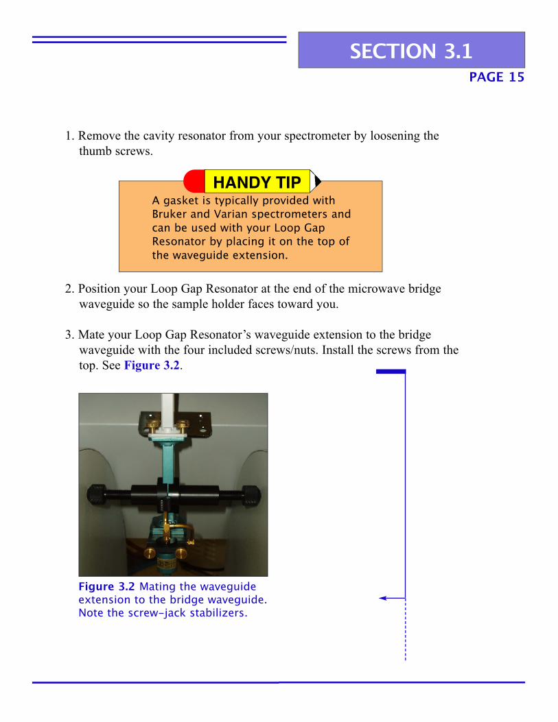
Figure 3.2 Mating the waveguideextension to the bridge waveguide.Note the screw-jack stabilizers.
1. Remove the cavity resonator from your spectrometer by loosening the thumb screws.
2. Position your Loop Gap Resonator at the end of the microwave bridge waveguide so the sample holder faces toward you.
3. Mate your Loop Gap Resonator’s waveguide extension to the bridge waveguide with the four included screws/nuts. Install the screws from thetop. See Figure 3.2.
A gasket is typically provided with Bruker and Varian spectrometers and can be used with your Loop Gap Resonator by placing it on the top of the waveguide extension.
HANDY TIP
SECTION 3.1

PAGE 16
Figure 3.3 Centering the resonatorpiece between the magnet polepieces. Note the position of theHall Probe on the left magnet pole.
4. Adjust the position of the microwave bridge so the resonator piece is centered between the magnet pole pieces. See Figure 3.3.
TROUBLESHOOTING
TIPThe Hall Probe is a sensor for themagnetic field. Your modulation coil should not be touching it.Contact Molecular Specialties for further instructions if the Hall Probe is too close to the center of the pole face andinterferes with securing the modulation coil. See Page 5.
SECTION 3.1
Place screw-jack stabilizers on either side of the waveguide extension and tighten. This helps to reduce vibration.See Figure 3.2 for an example.
HANDY TIP
PAGE 17
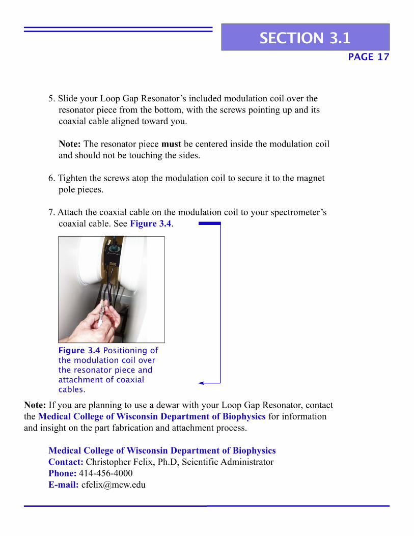
5. Slide your Loop Gap Resonator’s included modulation coil over the resonator piece from the bottom, with the screws pointing up and its coaxial cable aligned toward you.
Note: The resonator piece must be centered inside the modulation coil and should not be touching the sides.
6. Tighten the screws atop the modulation coil to secure it to the magnet pole pieces.
7. Attach the coaxial cable on the modulation coil to your spectrometer’scoaxial cable. See Figure 3.4.
Figure 3.4 Positioning ofthe modulation coil overthe resonator piece andattachment of coaxialcables.
SECTION 3.1
Note: If you are planning to use a dewar with your Loop Gap Resonator, contactthe Medical College of Wisconsin Department of Biophysics for informationand insight on the part fabrication and attachment process.
Medical College of Wisconsin Department of BiophysicsContact: Christopher Felix, Ph.D, Scientific AdministratorPhone: 414-456-4000E-mail: [email protected]
PAGE 18
Preparing Test SamplesYour test sample (both liquids and solids) will be placed in either a glass tube orMolecular Specialties’ TPX Capillary (Catalog No. TPX-2).
A sealant – typically a clay or wax – must be applied to the end of the tube or TPXCapillary to prevent escape of the sample during testing. Popular sealants include:
• Fisherbrand Hemato-Seal Tube Sealing Compound (Catalog No. 02-678)
• Bruker X-Sealant (Catalog No. 6130900)
• Oxford Labware Critoseal (Catalog No. 8889-215003)
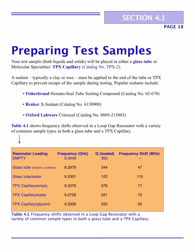
Table 4.1 shows frequency shifts observed in a Loop Gap Resonator with a varietyof common sample types in both a glass tube and a TPX Capillary.
Resonator Loading Frequency (GHz) Q (loaded) Frequency Shift (MHz)EMPTY 9.3446 360 –
Glass tube (0.6mm x 0.84mm) 9.2979 344 47
Glass tube/water 9.2301 122 115
TPX Capillary/empty 9.3276 379 17
TPX Capillary/water 9.2726 221 72
TPX Capillary/glycerol 9.2926 225 52
Table 4.1 Frequency shifts observed in a Loop Gap Resonator with avariety of common sample types in both a glass tube and a TPX Capillary.
SECTION 4.1
PAGE 19
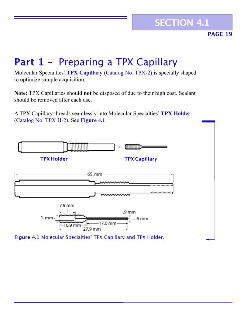
Molecular Specialties’ TPX Capillary (Catalog No. TPX-2) is specially shapedto optimize sample acquisition.
Note: TPX Capillaries should not be disposed of due to their high cost. Sealantshould be removed after each use.
A TPX Capillary threads seamlessly into Molecular Specialties’ TPX Holder(Catalog No. TPX H-2). See Figure 4.1.
TPX CapillaryTPX Holder
Figure 4.1 Molecular Specialties’ TPX Capillary and TPX Holder.
SECTION 4.1
Part 1 – Preparing a TPX Capillary
6. Thread the TPX Holder into the resonator piece and conduct your experiment.
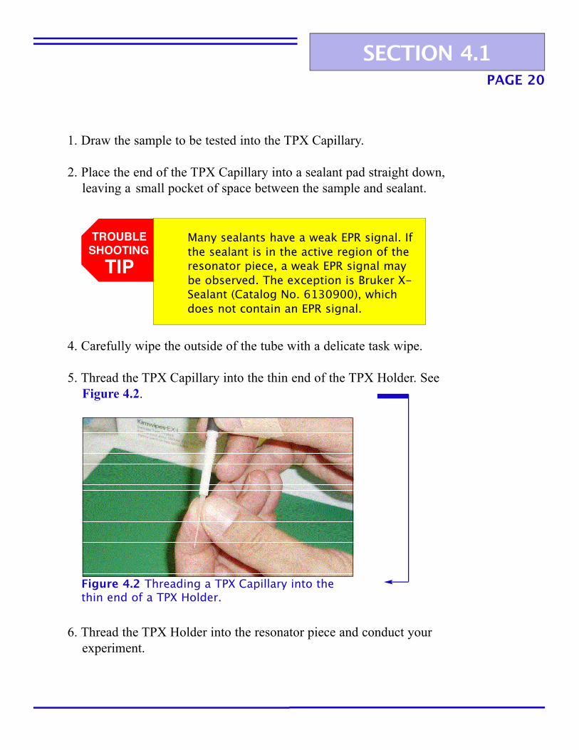
4. Carefully wipe the outside of the tube with a delicate task wipe.
5. Thread the TPX Capillary into the thin end of the TPX Holder. See Figure 4.2.
Figure 4.2 Threading a TPX Capillary into thethin end of a TPX Holder.
TROUBLESHOOTING
TIPMany sealants have a weak EPR signal. If the sealant is in the active region of the resonator piece, a weak EPR signal may be observed. The exception is Bruker X-Sealant (Catalog No. 6130900), which does not contain an EPR signal.
PAGE 20
1. Draw the sample to be tested into the TPX Capillary.
2. Place the end of the TPX Capillary into a sealant pad straight down, leaving a small pocket of space between the sample and sealant.
SECTION 4.1
PAGE 21
7. Dispose of your test sample following the experiment.
8. Acquire a small piece of 26AWG copper-coated wire and create a small kink at the end with your thumb and forefinger.
9. Slide the wire kink-first through the TPX Capillary and rotate, which willeliminate leftover sealant.
TROUBLESHOOTING
TIPSlide the wire completely through the TPX Capillary. Do not pull it backbecause you will spread sealantthroughout the inner cavity.
10. Acquire a squeeze bottle of distilled water with a tapered end. Placethe tapered end on the larger end of the TPX Capillary and squeeze water through it.
11. Repeat Step 10 with ethanol.
To dry more quickly, squeeze the end of a nitrogen gas tube around the larger end of the TPX Capillary so it forces the gas through it.
HANDY TIP
SECTION 4.1

3. Place the fire-polished end of the sample tube into the sample material.
Note: An aqueous sample will automatically be drawn in via capillary action. A hydrophobic sample may require suction to be drawn into the tube. For solids, place the glass tube on top of the sample and lightly tap the top to induce an amount to enter the tube.
Glass tubes have sharp ends that could scratch or damage the silver coating of theinterior of the resonator piece. Thus, it is imperative you polish the end of the sample tube to make it smooth before placing it in the resonator piece.
Molecular Specialties recommends VitroCom Round Capillary Tubing (CatalogNo. CV6084) for use with your Loop Gap Resonator.
1. Ignite a Meeker burner or a natural gas/oxygen torch.
2. Place the tip of the glass tube into the flame for a few seconds. This smooths the end of the tube and limits the chance of scratching the inside of the resonator piece.
PAGE 22
TROUBLESHOOTING
TIPIf you leave the glass tube in the flame too long, the tip may close, bend, or develop a “glob” so it will no longercorrectly fit into the resonator piece.
SECTION 4.1
Part 2 – Preparing a Glass Tube
PAGE 23
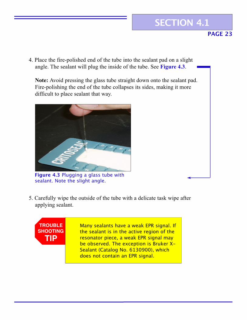
4. Place the fire-polished end of the tube into the sealant pad on a slight angle. The sealant will plug the inside of the tube. See Figure 4.3.
Note: Avoid pressing the glass tube straight down onto the sealant pad. Fire-polishing the end of the tube collapses its sides, making it more difficult to place sealant that way.
Figure 4.3 Plugging a glass tube withsealant. Note the slight angle.
SECTION 4.1
5. Carefully wipe the outside of the tube with a delicate task wipe after applying sealant.
TROUBLESHOOTING
TIPMany sealants have a weak EPR signal. If the sealant is in the active region of the resonator piece, a weak EPR signal may be observed. The exception is Bruker X-Sealant (Catalog No. 6130900), whichdoes not contain an EPR signal.
PAGE 24
6. Place the tube in the Loop Gap Resonator’s included sample holder and conduct your experiment.
7. Dispose of the tube following the experiment.
SECTION 4.1

PAGE 25
Tuning a Bruker ELEXSYSE 500 Spectrometer forYour Loop Gap ResonatorTuning any spectrometer for use with your Loop Gap Resonator is a process thatyou will master in time through repetition. The following instructions are a usefulguide for beginning that process with the Bruker ELEXSYS E 500spectrometer. See Figure 5.1 to view Molecular Specialties’ Loop Gap Resonatorattached to a Bruker ELEXSYS E 500 spectrometer.
(Refer to your Bruker ELEXSYS E 500 operator’s manual for furthertuning information.)
SECTION 5.1
Figure 5.1 Molecular Specialties’ Loop Gap Resonator attached to aBruker ELEXSYS E 500 spectrometer.

PAGE 26SECTION 5.1
3. Click the Tuning button, located third from left on the bottom toolbar.The Microwave Bridge Tuning dialog box will pop up.
4. Confirm the Attenuation is between 33-43 dB. Use the arrow functions toadjust, if necessary.
1. Carefully place your sample tube or TPX Capillary/Holder in theresonator piece.
2. Confirm you are beginning at the Bruker ELEXSYS E 500 Xepr Main Panel default screen.
TROUBLESHOOTING
TIPYou will utilize the bottom toolbar on theBruker ELEXSYS E 500 Xepr Main Paneldefault screen often when tuning andcalibrating the spectrometer for usewith your Loop Gap Resonator.
Part 1 – Searching for Resonance

Figure 5.2 Exampleof a signal line.
5. The signal will appear as a green line on the signal screen within the Microwave Bridge Tuning dialog box. See Figure 5.2.
6. Search for the resonant dip using the Frequency slider in the upper right corner of the Microwave Bridge Tuning dialog box.
PAGE 27SECTION 5.1
PAGE 28
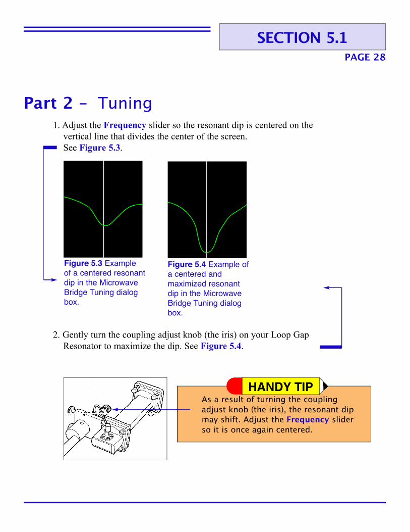
Figure 5.3 Example of a centered resonantdip in the MicrowaveBridge Tuning dialogbox.
Figure 5.4 Example ofa centered andmaximized resonantdip in the MicrowaveBridge Tuning dialogbox.
1. Adjust the Frequency slider so the resonant dip is centered on the vertical line that divides the center of the screen.See Figure 5.3.
2. Gently turn the coupling adjust knob (the iris) on your Loop Gap Resonator to maximize the dip. See Figure 5.4.
SECTION 5.1
Part 2 – Tuning
As a result of turning the couplingadjust knob (the iris), the resonant dip may shift. Adjust the Frequency slider so it is once again centered.
HANDY TIP

PAGE 29
5. Click Operate, located next to the signal screen in the Microwave Bridge Tuning dialog box.
6. Adjust the Frequency slider so the Lock Offset meter is at zero.
7. Click Reference Arm to Off.
8. Decrease the Attenuation by clicking the down-arrow function to 25-30. Adjust the Frequency slider if necessary so the Lock Offset meter is at zero.
9. Gently turn the coupling adjust knob (the iris) of your Loop Gap Resonator so it minimizes the Diode Current as close to zero as possible.
Note: See Figure 5.5 on the next page to view the ELEXSYS Diode Current and Lock Offset meters and their relationship to the innerworkings of a microwave bridge.
TROUBLESHOOTING
TIPThere is interdependence between the Frequency, Bias, and Signal Phasesliders within the Microwave Bridge Tuning dialog box. Adjusting one mayaffect the others.
SECTION 5.1
3. Click the Reference Arm to On.
4. Adjust the Bias slider so it is near the center of its range. Then adjust the Signal Phase slider to minimize the resonant dip. Both sliders are located under the Frequency slider.

PAGE 30
Figure 5.5 Schematic of the inner operation of a microwave bridge. Note the Diode Currentand Lock Offset meters seen on the Bruker ELEXSYS E 500 Xepr Main Panel defaultscreen. Meters from a Varian E-Line Century Series spectrometer are shown forcomparison.
SECTION 5.1

PAGE 31
You may use a modulation coil otherthan the one included with your LoopGap Resonator.
10. Click the Reference Arm to On and adjust the Bias slider so the Diode Current is about 200 µA.
11. Click Close to close the Microwave Bridge Tuning dialog box.
12. If you have not previously calibrated your Bruker ELEXSYSspectrometer for your Loop Gap Resonator and modulation coil, turn to Section 5.3, “Calibrating a Bruker ELEXSYS E 500 Spectrometer for Your Loop Gap Resonator.” See Page 35.
If you have previously calibrated, turn to Part 3 in this section, “IfPreviously Calibrated ...” See Page 32.
HANDY TIP
SECTION 5.1
If your sample contains water, it willheat as you increase microwave power. The microwave characteristics will change,and may cause the resonant frequencyof your Loop Gap Resonator to change,in addition to effecting a rise in theDiode Current meter. To cool your sampleand resonator piece, attach a hose to the air nozzle under the resonator piece and blow dry nitrogen gas.
HANDY TIP
PAGE 32SECTION 5.1
1. If your Bruker ELEXSYS spectrometer has already been calibrated for the modulation coil you are using, click Acquisition on the top Menu Bar. Click Spectrometer Configuration, and the Spectrometer Configuration dialog box will pop up.
2. Click the Signal Channel button. Under the field Standard Calibration Data, choose the data set corresponding to the modulationcoil you are using.
3. Click Close.
4. Acquire a spectrum. (Refer to your Bruker ELEXSYS E 500 operator’s manual for information on this process.)
5. When you have finished or are ready to change samples, click the Tuning button, located third from the left on the bottom toolbar. The Microwave Bridge Tuning dialog box will pop up.
6. Confirm the Attenuation is between 33-43 dB. Use the Arrow functionsto adjust, if necessary.
7. Confirm you are in the Tune mode.
8. Remove your sample.
Part 3 - If Previously Calibrated ...
TROUBLESHOOTING
TIPAlways confirm the Attenuation isbetween 33-43 dB and you are in theTune mode when inserting or removinga sample.

PAGE 33
For Microwave Bridgeswith Stabilizer Frequency Some microwave bridges are equipped with a Stabilizer Frequency dial on theupper left side of the front face of the bridge. See Figure 5.6.
It is used when the researcher desires operation at a power level where the AFC isnot able to lock onto resonator mode. The following procedure allows you to usethis option when tuning a Bruker ELEXSYS E 500 for your Loop Gap Resonator.
1. Click the Tuning button, located third from left on the bottom toolbar.The Microwave Bridge Tuning dialog box will pop up.
2. Confirm you are in the Tune mode in the Microwave Bridge Tuning dialog box.
3. Click the box next to Dual Trace.
4. Click the On button under the Stabilizer Frequency dial on the microwave bridge.
Figure 5.6 Microwave bridge with Stabilizer Frequency dial.
SECTION 5.2

PAGE 34
5. Adjust the Stabilizer Frequency dial on the microwave bridge by hand so the yellow stabilizer mode line curves up and aligns with the greenresonator dip line, which curves down. See Figure 5.7.
6. Click the box next to Dual Trace.
7. Click Close.
Figure 5.7 Alignmentof stabilizer modeand resonator diplines. In this display,the stabilizerfrequency is yellowand the resonant dipis green. The colorsmay be reversed onsome spectrometers.
SECTION 5.2

Calibrating a Bruker ELEXSYSE 500 Spectrometer for YourLoop Gap Resonator
PAGE 35
You must calibrate your Bruker ELEXSYS E 500 spectrometer for use with yourLoop Gap Resonator’s modulation coil prior to its initial use. The calibrationinformation is stored on the ELEXSYS E 500’s computer, and you will refer to itwhenever you use your Loop Gap Resonator with it.
If you do not calibrate, you will not know your modulation amplitude and phase,and you could get less than maximum signal, or potentially no signal.
(Refer to your Bruker ELEXSYS E 500 operator’s manual for furthercalibration information.)
SECTION 5.3
PAGE 36SECTION 5.3
1. Place your calibration sample in the resonator piece and follow the tuningprocedure described in Section 5.1, “Tuning a Bruker ELEXSYS E 500 Spectrometer for a Loop Gap Resonator.” See Page 25.
2. Click the Tuning button, located third from left on the bottom toolbar.The Microwave Bridge Tuning dialog box will pop up.
3. Confirm you are in the Operate mode in the Microwave Bridge Tuning dialog box.
4. Click the Create an Experiment button, located on the extreme left of the bottom toolbar. The Build Experiment dialog box will pop up.
5. Type “calibration” in the Experiment Name field.
6. Click the Calib tab. Then click Standard in the middle of the dialog box.
7. Click Create.
TROUBLESHOOTING
TIPTo calibrate your Loop Gap Resonator’s modulation coil for the first time,use a sample that will provide a single-line spectrum of moderate width. Molecular Specialties recommends a solution of 1g of sodium dithionite per 20mL of water, or DPPH crystals.
Part 1 – Pre-calibration

1. Click the Parameters button, located fourth from left on the bottomtoolbar. The Calibration Parameters dialog box will pop up.
TROUBLESHOOTING
TIPIn the Calibration Parameters dialog box, you may calibrate for many frequencies, or you may calibrate for the defaultsettings displayed. The followingconfiguration is recommended for yourLoop Gap Resonator:• Mod. Frequency Start [kHz]: 100 kHz• Mod. Frequency End [kHz]: 10 kHz• Mod. Frequency Incr. [kHz]: 10 kHz
PAGE 37SECTION 5.3
Part 2 – Calibration
2. Click the Setup Scan button, and then the Setup Scan box. You should see an EPR signal. See Figure 5.8.
Figure 5.8 An EPRsignal viewed afterclicking the SetupScan box.
If you do not see a signal at all, click on the Parameters button. The Calibration Parameters dialog box will pop up. Click the Absc. 1: Field tab. Under Abscissa 1 Sweep Quantity: Field, type in “3300” in the Center Field field. Click Setup Scan.

4. Click the Results tab in the Calibration Parameters dialog box. Data should be entered in the cells of the six-column grid under the Calibration Results field.
5. Click Close when calibration is completed.
PAGE 38
Note: Depending on the resonator frequency, you may have to modify the Center Field value.
If you still do not see a signal, click on the Calibration tab and type “12” in the Tuning C field. Then complete the following procedure:
A. Decrease the Receiver Gain under Signal Channel until the signal in the Setup Scan box is less than half the height of the window.
B. Click on the Results tab and type in a new calibration name in the Calibration Data field (Example: “MolSpecCalib”). Click Setup Scan.
Figure 5.9 The Run/AbortExperiment button.
SECTION 5.3
3. Click the Run/Abort Experiment button located in the extreme lower left corner of the Bruker ELEXSYS E 500 Xepr Main Panel default screen. See Figure 5.9. The spectrometer will then take several minutes to sweep the field.
TROUBLESHOOTING
TIPBe sure to type in a new name in theCalibration Data field. If you do not,you will erase the previous calibrationand replace it with the Loop GapResonator’s calibration values.
PAGE 39
1. Click Acquisition on the top Menu Bar.
2. Click Spectrometer Configuration. The Spectrometer Configuration dialog box will pop up.
3. Click the Signal Channel tab.
4. Click Calibration Data Set under Standard Calibration Data. The name of your calibration should be there.
TROUBLESHOOTING
TIPWhenever you perform an experiment using your Loop Gap Resonator and itsmodulation coil, you will choose thecalibration data set you created in Section 5.3 before you attempt to acquire a spectrum. Follow the directions in Section 5.1, Part 3, clicking on the name of your calibration before attempting to acquire a spectrum. See Page 32.
SECTION 5.3
Part 3 – Confirmation

PAGE 40S U P P O R T
Appendix Quality Control Test
1. Prepare a 10 µM Tempone sample in a 0.6mm i.d. glass tube.
2. Install your Loop Gap Resonator on your spectrometer and after placing the glass tube with the sample material into the resonator piece, tune thespectrometer. See Section 5.1, “Tuning a Bruker ELEXSYS E 500Spectrometer for Your Loop Gap Resonator,” for information on thisprocess. See Page 25.
1. Set your spectrometer to the settings below and acquire a spectrum.
Center field As necessaryScan range 50 GaussPower 2.5 mWModulation frequency 100 kHzModulation field intensity settings 1 GaussReceiver gain 5 x 10²
Receiver time constant 1 secondScan time 2 minutes
Note: Adjust the receiver gain to maximize the signal on the plot.
Part 1 – Preparation
Part 2 – Measuring Signal

PAGE 41S U P P O R T
Part 3 – Measuring Noise
Part 4 – Calculations
1. Change the following settings on your spectrometer and acquire aspectrum:
Center field 3,500 GaussScan range 0 GaussReceiver gain 5 x 10⁴
Receiver time constant 1 secondScan time 2 minutes
1. Calculate the signal-to-noise ratio using the following equation:
S h1 x G2
N h2 x G1
Equation values:h1 – the peak-to-peak height of the largest spectra from Part 2 in
centimeters
h2 – the peak-to-peak height of the largest noise amplitude from Part 3in centimeters divided by 2.5 to arrive at an estimate of RMS noise.
G1 – Receiver gain setting in Part 2
G2 – Receiver gain setting in Part 3
2. The equation should result in a signal-to-noise calculation of 1,500 or greater.
Appendix (cont’d)
PAGE 42S U P P O R T
R.D. Allendoerfer, W. Froncisz, C.C. Felix, and J.S. Hyde, Electrochemical Generation of FreeRadicals in an EPR Loop-Gap Resonator, J. Magn. Reson. 76, 100-105 (1988).
R. Basosi, W. E. Antholine, W. Froncisz, and J.S. Hyde, Spin-Hamiltonian Input Parameters inthe EPR Analysis of Liquid Phase Copper Complexes, J. Chem. Phys. 81, 4849-4857 (1984).
T. Christides, W. Froncisz, T. Oles, and J.S. Hyde, Probehead with Interchangeable Loop-GapResonators and rf Coils for Multifrequency EPR/ENDOR, Rev. Sci. Instrum. 65, 63-67 (1994).
W. Froncisz and J.S. Hyde, The Loop-Gap Resonator: A New Microwave Lumped Circuit ESRSample Structure, J. Magn. Reson. 47, 515-521 (1982).
W. Froncisz, T. Oles, and J.S. Hyde, Murine L-Band ESR Loop-Gap Resonator, J. Magn.Reson. 82, 109-114 (1989).
W. Froncisz, T. Oles, and J.S. Hyde, Q-Band Loop-Gap Resonator, Rev. Sci. Instrum. 57, 1095-1099 (1986).
W.L. Hubbell, W. Froncisz, and J.S. Hyde, Continuous and Stopped-Flow EPR SpectrometerBased on a Loop-Gap Resonator, Rev. Sci. Instrum. 58, 1879-1886 (1987).
J.S. Hyde and W. Froncisz, Loop Gap Resonators, in: Advanced EPR: Applications in Biologyand Biochemistry, A.J. Hoff, ed. (Elsevier: Amsterdam, 1989), pp. 277-306.
J.S. Hyde and W. Froncisz, Loop-Gap Resonators, in: Electron Spin Resonance, M.C.R.Symons, ed. (Specialist Periodical Reports, The Royal Society of Chemistry: London, 1986),Vol. 10, pp. 175-184.
J.S. Hyde, W. Froncisz, and A. Kusumi, Dispersion Electron Spin Resonance with the Loop-Gap Resonator, Rev. Sci. Instrum. 53, 1934-1937 (1982).
J.S. Hyde, W. Froncisz, and T. Oles, Multipurpose Loop-Gap Resonator, J. Magn. Reson. 82,223-230 (1989).
J.S. Hyde and J. Gajdzinski, EPR Automatic Frequency Control Circuit with Field EffectTransistor (FET) Microwave Amplification, Rev. Sci. Instrum. 59, 1352-1356 (1988).
Bibliography

PAGE 43S U P P O R T
Bibliography (cont’d)J.S. Hyde, J.-J. Yin, W. Froncisz, and J.B. Feix, Electron-Electron Double Resonance (ELDOR)with a Loop-Gap Resonator, J. Magn. Reson. 63, 142-150 (1985).
C. S. Klug, J.F. Feix, SDSL: A Survey of Biological Applications in Biological MagneticResonance, Volume 24: Biomedical EPR – Part B: Methodology and Instrumentation, S.S.Eaton, G.R. Eaton, L.J. Berliner, eds. (Kluwer Academic/Plenum Publishers, New York 2004),pp. 269-308.
M. Mehdizadeh, T.K. Ishii, J.S. Hyde and W. Froncisz, Loop-Gap Resonator: A Lumped ModeMicrowave Resonant Structure, IEEE Trans. Microwave Theory Tech. MTT31, 1059-1064(1983).
T. Oles, J.S. Hyde, and W. Froncisz, Gordon Coupler for K-Band EPR Loop Gap Resonator,Rev. Sci. Instrum. 60, 389-391 (1989).
S. Pfenninger, W. Froncisz, J. Forrer, J. Luglio, and J.S. Hyde, General Method for Adjustingthe Quality Factor of EPR Resonators, Rev. Sci. Instrum. 66, 4857-4865 (1995).
W. Piasecki, W. Froncisz, and J.S. Hyde, Bimodal Loop-Gap Resonator, Rev. Sci. Instrum. 67,1896-1904 (1996).
K.S. Rothenberger, M.J. Nilges, T.E. Altman, K. Glab, R.L. Belford, W. Froncisz, and J.S.Hyde, L-Band Parallel Mode EPR Measurement of Quadrupole Coupling Through DirectObservation of Secondary Transitions, Chem. Phys. Lett. 124, 295-298 (1986).
W.K. Subczynski, S. Lukiewicz, and J.S. Hyde, Murine in Vivo L-Band ESR Spin-LabelOximetry with a Loop-Gap Resonator, Magn. Reson. Med. 3, 747-754 (1986).
D.D. Thomas, C.H. Wendt, W. Froncisz, and J.S. Hyde, Saturation Transfer EPR Spectroscopyon Spin-labeled Muscle Fibers Using a Loop-Gap Resonator, Biophys. J. 43, 131-135 (1983).
A.I. Tsapin, J.S. Hyde, and W. Froncisz, Bimodal Loop-Gap Resonator, J. Magn. Reson. 100,484-490 (1982).
R.L. Wood, W. Froncisz, and J.S. Hyde, The Loop-Gap Resonator. II. Controlled Return FluxThree-Loop, Two-Gap Microwave Resonators for ENDOR and ESR Spectroscopy, J. Magn.Reson. 58, 243-253 (1984).

PAGE 44S U P P O R T
IndexAcetone 12
AFC 33
Bruker 14-15, 18, 20, 23, 25-26, 30-33, 35-36, 38, 40
X-Sealant 18, 20, 23ELEXSYS E 500 Spectrometer 25-26,29-33, 35-36, 40Diode Current meter 29-31Lock Offset meter 29, 30Stabilizer Frequency 33-34Xepr Main Panel default screen 26, 30, 38
Dewar 6, 17
DPPH crystals 36
EPR (Electron ParamagneticResonance) 5-6, 9, 20, 23, 37, 42-43
Ethanol 12, 21
Gasket 15
Glass tube 8, 11, 18, 22-23, 40VitroCom 22
Glycerol 18
Hall Probe 5, 16
Iris (see Loop Gap Resonator, Couplingadjust knob)
Loop Gap Resonator 4-7, 9-10, 12-15,17-18, 22, 24-28, 29, 31, 33, 35-37, 39-40, 42-43
Cleaning 12Coupling adjust knob 7, 13, 28-29Hose barb 6, 7Installation 14Modification capability 6Modulation coil 5-8, 16-17, 31-32, 35-36, 39Optimal experiments 9Ordering 5Preventive maintenance 12Proper handling 13Quality control testing 8, 40-41Q (Quality) Factor 6, 8-9, 18Resonator piece 6, 10-13, 16-17, 20, 22-23, 26, 31, 36, 40Sensitivity 6Technical data 8Temperature control 6Warranty 6, 12Waveguide extension 7-8, 15-16
Meeker burner 22
Medical College of WisconsinDepartment of Biophysics 3, 17
Microwave bridge 5, 14-16, 29-30, 33-34
Molecular Specialties, Inc. 5-7, 11-13,16, 18-19, 22, 25, 36
PAGE 45S U P P O R T
Index (cont’d)Natural gas/oxygen torch 22
Nitrogen gas 12, 21, 31
Quartz Tube (see Glass Tube)
Screw-jack stabilizers 15-16
Sealant 18-21, 23Bruker X-Sealant 18, 20, 23Fisherbrand Hemato-Seal Tube Compound 18Oxford Labware Critoseal 18
Sodium dithionite 36
Spectrum acquisition 32, 36, 39-41
Stop-flow studies 6, 9
Tempone 8, 40
TPX Capillary 6, 8, 11, 18-19, 20-21, 26
TPX Holder 11, 19-20, 26
Update Instruments 9
Varian 14-15, 30AFC meter 30Current detector 30

PAGE 46S U P P O R T
Notes

PAGE 47S U P P O R T
Notes


![A MINIATURIZED OPEN-LOOP RESONATOR FILTER … · loop resonator ends [7]. A circuit adopts the structure of the °oating plate overlays to efiectively increase the capacitive coupling](https://static.fdocuments.us/doc/165x107/5cd83eaa88c9938f428b45b1/a-miniaturized-open-loop-resonator-filter-loop-resonator-ends-7-a-circuit.jpg)
